1
NT-series
NT20M/NT600M Support Tool
Operation Manual
Revised August 1993
Notice:
OMRON products are manufactured for use according to proper procedures by a qualified operator
and only for the purposes described in this manual.
The following conventions are used to indicate and classify precautions in this manual. Always heed
the information provided with them. Failure to head precautions can result in injury to people or damage to the product.
DANGER!
Indicates information that, if not heeded, is likely to result in loss of life or serious
injury.
WARNING Indicates information that, if not heeded, could possibly result in loss of life or
serious injury.
Caution
Indicates information that, if not heeded, could result in relative serious or minor
injury, damage to the product, or faulty operation.
OMRON Product References
All OMRON products are capitalized in this manual. The word “Unit” is also capitalized when it refers
to an OMRON product, regardless of whether or not it appears in the proper name of the product.
The abbreviation “Ch,” which appears in some displays and on some OMRON products, often means
“word” and is abbreviated “Wd” in documentation in this sense.
The abbreviation “PC” means Programmable Controller and is not used as an abbreviation for anything else.
Visual Aids
The following headings appear in the left column of the manual to help you locate different types of
information.
Note Indicates information of particular interest for efficient and convenient operation of the product.
1, 2, 3... Indicates lists of one sort or another, such as procedures, precautions, etc.
OMRON, 1991
All rights reserved. No part of this publication may be reproduced, stored in a retrieval system, or transmitted, in any
form, or by any means, mechanical, electronic, photocopying, recording, or otherwise, without the prior written permission of OMRON.
No patent liability is assumed with respect to the use of the information contained herein. Moreover, because OMRON is
constantly striving to improve its high-quality products, the information contained in this manual is subject to change
without notice. Every precaution has been taken in the preparation of this manual. Nevertheless, OMRON assumes no
responsibility for errors or omissions. Neither is any liability assumed for damages resulting from the use of the information contained in this publication.
v
TABLE OF CONTENTS
SECTION 1
Introduction . . . . . . . . . . . . . . . . . . . . . . . . . . . . . . . . . . . . .
1-1
1-2
1-3
1-4
1-5
1-6
1-7
1-8
1-9
1-10
1-11
1-12
1-13
1-14
1-15
Terminology and NT-series Manuals . . . . . . . . . . . . . . . . . . . . . . . . . . . . . . . . . . . . . . . . . .
Using Older Models . . . . . . . . . . . . . . . . . . . . . . . . . . . . . . . . . . . . . . . . . . . . . . . . . . . . . . .
System Configuration . . . . . . . . . . . . . . . . . . . . . . . . . . . . . . . . . . . . . . . . . . . . . . . . . . . . . .
Creating a Work Disk . . . . . . . . . . . . . . . . . . . . . . . . . . . . . . . . . . . . . . . . . . . . . . . . . . . . . .
Starting and Exiting . . . . . . . . . . . . . . . . . . . . . . . . . . . . . . . . . . . . . . . . . . . . . . . . . . . . . . .
Main Menu . . . . . . . . . . . . . . . . . . . . . . . . . . . . . . . . . . . . . . . . . . . . . . . . . . . . . . . . . . . . . .
File Selection . . . . . . . . . . . . . . . . . . . . . . . . . . . . . . . . . . . . . . . . . . . . . . . . . . . . . . . . . . . .
Screen Selection . . . . . . . . . . . . . . . . . . . . . . . . . . . . . . . . . . . . . . . . . . . . . . . . . . . . . . . . . .
Inputting Screen Comments, File Names, and Titles . . . . . . . . . . . . . . . . . . . . . . . . . . . . . .
Editing Screens . . . . . . . . . . . . . . . . . . . . . . . . . . . . . . . . . . . . . . . . . . . . . . . . . . . . . . . . . . .
Inputting Character Strings and Numbers . . . . . . . . . . . . . . . . . . . . . . . . . . . . . . . . . . . . . .
Basic Operation . . . . . . . . . . . . . . . . . . . . . . . . . . . . . . . . . . . . . . . . . . . . . . . . . . . . . . . . . .
Tool Settings . . . . . . . . . . . . . . . . . . . . . . . . . . . . . . . . . . . . . . . . . . . . . . . . . . . . . . . . . . . . .
Environment Settings . . . . . . . . . . . . . . . . . . . . . . . . . . . . . . . . . . . . . . . . . . . . . . . . . . . . . .
Direct Connection . . . . . . . . . . . . . . . . . . . . . . . . . . . . . . . . . . . . . . . . . . . . . . . . . . . . . . . .
SECTION 2
Creating Screens . . . . . . . . . . . . . . . . . . . . . . . . . . . . . . . . .
2-1
2-2
2-3
2-4
2-5
2-6
2-7
2-8
2-9
2-10
2-11
2-12
2-13
2-14
2-15
2-16
Inputting Character Strings . . . . . . . . . . . . . . . . . . . . . . . . . . . . . . . . . . . . . . . . . . . . . . . . .
Numeral Displays . . . . . . . . . . . . . . . . . . . . . . . . . . . . . . . . . . . . . . . . . . . . . . . . . . . . . . . . .
Character String Displays . . . . . . . . . . . . . . . . . . . . . . . . . . . . . . . . . . . . . . . . . . . . . . . . . . .
Lamps . . . . . . . . . . . . . . . . . . . . . . . . . . . . . . . . . . . . . . . . . . . . . . . . . . . . . . . . . . . . . . . . . .
Touch Switches . . . . . . . . . . . . . . . . . . . . . . . . . . . . . . . . . . . . . . . . . . . . . . . . . . . . . . . . . .
Bar Graphs . . . . . . . . . . . . . . . . . . . . . . . . . . . . . . . . . . . . . . . . . . . . . . . . . . . . . . . . . . . . . .
Editing Memory Tables . . . . . . . . . . . . . . . . . . . . . . . . . . . . . . . . . . . . . . . . . . . . . . . . . . . .
Numeral Editing . . . . . . . . . . . . . . . . . . . . . . . . . . . . . . . . . . . . . . . . . . . . . . . . . . . . . . . . . .
Polylines . . . . . . . . . . . . . . . . . . . . . . . . . . . . . . . . . . . . . . . . . . . . . . . . . . . . . . . . . . . . . . . .
Circles . . . . . . . . . . . . . . . . . . . . . . . . . . . . . . . . . . . . . . . . . . . . . . . . . . . . . . . . . . . . . . . . . .
Continuous and Overlapping Screens . . . . . . . . . . . . . . . . . . . . . . . . . . . . . . . . . . . . . . . . .
Screen Attributes . . . . . . . . . . . . . . . . . . . . . . . . . . . . . . . . . . . . . . . . . . . . . . . . . . . . . . . . .
Screen Check . . . . . . . . . . . . . . . . . . . . . . . . . . . . . . . . . . . . . . . . . . . . . . . . . . . . . . . . . . . .
Marks . . . . . . . . . . . . . . . . . . . . . . . . . . . . . . . . . . . . . . . . . . . . . . . . . . . . . . . . . . . . . . . . . .
Stand-alone Operation . . . . . . . . . . . . . . . . . . . . . . . . . . . . . . . . . . . . . . . . . . . . . . . . . . . . .
Edit . . . . . . . . . . . . . . . . . . . . . . . . . . . . . . . . . . . . . . . . . . . . . . . . . . . . . . . . . . . . . . . . . . . .
SECTION 3
Managing Screen Data . . . . . . . . . . . . . . . . . . . . . . . . . . . .
3-1
3-2
3-3
3-4
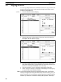
Copying Screens . . . . . . . . . . . . . . . . . . . . . . . . . . . . . . . . . . . . . . . . . . . . . . . . . . . . . . . . . .
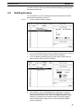
Deleting Screens . . . . . . . . . . . . . . . . . . . . . . . . . . . . . . . . . . . . . . . . . . . . . . . . . . . . . . . . . .
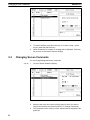
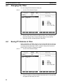
Changing Screen Comments . . . . . . . . . . . . . . . . . . . . . . . . . . . . . . . . . . . . . . . . . . . . . . . .
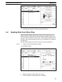
Reading Data from Other Files . . . . . . . . . . . . . . . . . . . . . . . . . . . . . . . . . . . . . . . . . . . . . .
SECTION 4
Managing File Data . . . . . . . . . . . . . . . . . . . . . . . . . . . . . . .
4-1
4-2
4-3
4-4
4-5
Copying Files . . . . . . . . . . . . . . . . . . . . . . . . . . . . . . . . . . . . . . . . . . . . . . . . . . . . . . . . . . . .
Deleting Files . . . . . . . . . . . . . . . . . . . . . . . . . . . . . . . . . . . . . . . . . . . . . . . . . . . . . . . . . . . .
Changing File Titles . . . . . . . . . . . . . . . . . . . . . . . . . . . . . . . . . . . . . . . . . . . . . . . . . . . . . . .
Saving PT Histories in Files . . . . . . . . . . . . . . . . . . . . . . . . . . . . . . . . . . . . . . . . . . . . . . . . .
Setting Initial Screens . . . . . . . . . . . . . . . . . . . . . . . . . . . . . . . . . . . . . . . . . . . . . . . . . . . . .
1
2
2
3
4
5
5
6
7
10
11
12
13
15
16
17
21
22
28
34
40
46
51
59
62
71
73
75
78
80
82
85
87
89
90
91
92
93
95
96
97
98
98
99
vii
SECTION 5
Printing . . . . . . . . . . . . . . . . . . . . . . . . . . . . . . . . . . . . . . . . .
5-1
5-2
5-3
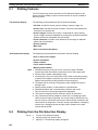
Printing Features . . . . . . . . . . . . . . . . . . . . . . . . . . . . . . . . . . . . . . . . . . . . . . . . . . . . . . . . .
Printing from the File Selection Display . . . . . . . . . . . . . . . . . . . . . . . . . . . . . . . . . . . . . . .
Printing from the Screen Selection Display . . . . . . . . . . . . . . . . . . . . . . . . . . . . . . . . . . . . .
SECTION 6
Transmitting Data . . . . . . . . . . . . . . . . . . . . . . . . . . . . . . . .
6-1
6-2
6-3
6-4
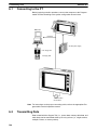
Connecting to the PT . . . . . . . . . . . . . . . . . . . . . . . . . . . . . . . . . . . . . . . . . . . . . . . . . . . . . .
Transmitting Data . . . . . . . . . . . . . . . . . . . . . . . . . . . . . . . . . . . . . . . . . . . . . . . . . . . . . . . . .
Receiving Data . . . . . . . . . . . . . . . . . . . . . . . . . . . . . . . . . . . . . . . . . . . . . . . . . . . . . . . . . . .
Deleting PT Screens . . . . . . . . . . . . . . . . . . . . . . . . . . . . . . . . . . . . . . . . . . . . . . . . . . . . . . .
SECTION 7
PROM Writer Operations . . . . . . . . . . . . . . . . . . . . . . . . .
7-1
7-2
7-3
7-4
Connecting to a PROM Writer . . . . . . . . . . . . . . . . . . . . . . . . . . . . . . . . . . . . . . . . . . . . . . .
Transmitting Data to a PROM Writer . . . . . . . . . . . . . . . . . . . . . . . . . . . . . . . . . . . . . . . . .
Transmitting Data with Verification to a PROM Writer . . . . . . . . . . . . . . . . . . . . . . . . . . .
Receiving Data from a PROM Writer . . . . . . . . . . . . . . . . . . . . . . . . . . . . . . . . . . . . . . . . .
Appendix: Special Characters . . . . . . . . . . . . . . . . . . . . . .
Index . . . . . . . . . . . . . . . . . . . . . . . . . . . . . . . . . . . . . . . . . . .
Revision History . . . . . . . . . . . . . . . . . . . . . . . . . . . . . . . . .
viii
101
102
102
103
105
106
106
110
114
117
118
118
119
120
123
125
127
About this Manual:
This manual describes the installation and operation of the Support Tool and includes the sections
described below. The Support Tool is a software package for creating and managing displays for the
NT20M and NT600M Programmable Terminals (PTs).
Please read this manual completely and be sure you understand the information provided before attempting to install and operation the Support Tool.
Section 1 provides an overview of Support Tool operation and its operating environment. Basic operating and input methods common to most Support Tool features are covered. The last section, Tool
Settings, describes how to set Support Tool operating parameters, which affect overall operation.
Section 2 describes the specific operations used to create displays for Programmable Terminals.
Special features include numeral displays, character string displays, lamps, and bar graphs, all of
which can be used to display on-screen data transferred to the PT from the PT’s host, and numeral
editing and touch switches, both of which can be used to input data on-screen for transfer to the host
from the PT.
Section 3 describes how to manage screens as whole units.
Section 4 describes how to manage files.
Section 5 describes how to print screen images.
Section 6 describes the setup and methods for transferring data between the Support Tool and the
PT. This section also includes remote operations for deleting screens from the PT.
Section 7 describes the setup and methods for transferring data between the Support Tool and a
PROM writer.
The Appendix provides a table of English character codes.
WARNING Failure to read and understand the information provided in this manual may result in
personal injury or death, damage to the product, or product failure. Please read each
section in its entirety and be sure you understand the information provided in the section
and related sections before attempting any of the procedures or operations given.
ix
SECTION 1
Introduction
This section outlines the operations of the Support Tool. It includes general operating procedures and installation procedures, as well as miscellaneous information, such as the functional limitations when creating screens for older PT models. Refer to the other sections in this manual for details on specific operations. Reference pages are given in this section
for many operations.
1-1
1-2
1-3
1-4
1-5
1-6
1-7
1-8
1-9
1-10
1-11
1-12
1-13
1-14
1-15
Terminology and NT-series Manuals . . . . . . . . . . . . . . . . . . . . . . . . . . . . . . . . . . . . . . . . . .
Using Older Models . . . . . . . . . . . . . . . . . . . . . . . . . . . . . . . . . . . . . . . . . . . . . . . . . . . . . . .
System Configuration . . . . . . . . . . . . . . . . . . . . . . . . . . . . . . . . . . . . . . . . . . . . . . . . . . . . . .
1-3-1 NT20M and NT600M Support Tool Operations . . . . . . . . . . . . . . . . . . . . . . . . . .
1-3-2 Menu Configuration . . . . . . . . . . . . . . . . . . . . . . . . . . . . . . . . . . . . . . . . . . . . . . . .
1-3-3 Support Tool System . . . . . . . . . . . . . . . . . . . . . . . . . . . . . . . . . . . . . . . . . . . . . . .
Creating a Work Disk . . . . . . . . . . . . . . . . . . . . . . . . . . . . . . . . . . . . . . . . . . . . . . . . . . . . . .
Starting and Exiting . . . . . . . . . . . . . . . . . . . . . . . . . . . . . . . . . . . . . . . . . . . . . . . . . . . . . . .
Main Menu . . . . . . . . . . . . . . . . . . . . . . . . . . . . . . . . . . . . . . . . . . . . . . . . . . . . . . . . . . . . . .
File Selection . . . . . . . . . . . . . . . . . . . . . . . . . . . . . . . . . . . . . . . . . . . . . . . . . . . . . . . . . . . .
Screen Selection . . . . . . . . . . . . . . . . . . . . . . . . . . . . . . . . . . . . . . . . . . . . . . . . . . . . . . . . . .
Inputting Screen Comments, File Names, and Titles . . . . . . . . . . . . . . . . . . . . . . . . . . . . . .
1-9-1 Screen Comments . . . . . . . . . . . . . . . . . . . . . . . . . . . . . . . . . . . . . . . . . . . . . . . . .
1-9-2 File Names and Titles . . . . . . . . . . . . . . . . . . . . . . . . . . . . . . . . . . . . . . . . . . . . . .
Editing Screens . . . . . . . . . . . . . . . . . . . . . . . . . . . . . . . . . . . . . . . . . . . . . . . . . . . . . . . . . . .
Inputting Character Strings and Numbers . . . . . . . . . . . . . . . . . . . . . . . . . . . . . . . . . . . . . .
Basic Operation . . . . . . . . . . . . . . . . . . . . . . . . . . . . . . . . . . . . . . . . . . . . . . . . . . . . . . . . . .
1-12-1 Cursors . . . . . . . . . . . . . . . . . . . . . . . . . . . . . . . . . . . . . . . . . . . . . . . . . . . . . . . . . .
1-12-2 Screen Buttons . . . . . . . . . . . . . . . . . . . . . . . . . . . . . . . . . . . . . . . . . . . . . . . . . . . .
1-12-3 Mouse . . . . . . . . . . . . . . . . . . . . . . . . . . . . . . . . . . . . . . . . . . . . . . . . . . . . . . . . . . .
1-12-4 Positioning Operations . . . . . . . . . . . . . . . . . . . . . . . . . . . . . . . . . . . . . . . . . . . . . .
Tool Settings . . . . . . . . . . . . . . . . . . . . . . . . . . . . . . . . . . . . . . . . . . . . . . . . . . . . . . . . . . . . .
Environment Settings . . . . . . . . . . . . . . . . . . . . . . . . . . . . . . . . . . . . . . . . . . . . . . . . . . . . . .
Direct Connection . . . . . . . . . . . . . . . . . . . . . . . . . . . . . . . . . . . . . . . . . . . . . . . . . . . . . . . .
1-15-1 Specifying PC Addresses for Direct Connection . . . . . . . . . . . . . . . . . . . . . . . . . .
1-15-2 Direct Connection Information . . . . . . . . . . . . . . . . . . . . . . . . . . . . . . . . . . . . . . .
2
2
3
3
3
4
4
5
5
6
7
10
10
10
11
12
13
13
14
14
14
15
16
17
18
19
1
Section 1-2
Using Older Models
1-1
Terminology and NT-series Manuals
Names of items in this manual related to the NT Series of Programmable Terminals and SYSMAC C-series Programmable Controllers are defined next.
Abbreviations
The following abbreviations are used in the text.
Abbreviation
Term
Meaning
PT
Programmable Terminal
Refers to an OMRON NT-series Programmable Terminal.
PC
Programmable
Controller
Refers to an OMRON SYSMAC C-series or CV-series Programmable
Controller, or programmable controllers manufactured by other companies.
I/F
interface
A communications device that connects the Programmable Terminal with
peripheral devices.
I/O
input/output
Refers to PT and PC inputs and outputs.
SYSMAC Terminology
Terminology
Explanation
SYSMAC
A generic name for OMRON’s Programmable Controllers.
Host Link System
(SYSMAC WAY)
A system employing SYSMAC C-series Host Link Units used to create a communications bus
between PCs, between PCs and PTs, etc.
SYSMAC BUS
A remote I/O network created between SYSMAC C-series PCs and input/output devices.
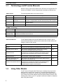
Reference Manuals
The NT20M/NT2000M Series and NT600M Series are covered in the six
manuals described below. Actual manual numbers also include suffixes indicating the version of the manual.
Name of Manual
Contents
Manual No.
NT20M/NT2000M Operation
Manual
This manual provides specifications, functions, and operating
instructions for the NT20M and NT2000M Programmable Terminals.
V001
NT600M Operation Manual
This manual provides specifications, functions, and operating
instructions for NT600M Programmable Terminals.
V002
NT-series Host Interface Unit
Operation Manual
This manual covers the commands, controls, and communications
specifications for operating the NT20M and the NT600M. Refer to
this manual when programming host computer communications.
V003
NT20M/NT600M Support Tool
Operation Manual
This manual covers methods for creating screens, including screen
data preparation, switches, lights, and alarms.
V004
NT-series Host Interface Unit
Direct Operation Manual
This manual covers the Direct Connection feature which has been
added to the Host Interface Unit.
V015
NT-series RS-232C/RS-422
Interface Unit Operation Manual
This manual covers the commands, controls, and communications
specifications for operating the NT20M and the NT600M with the
RS-232C/RS-422 Interface Unit. Refer to this manual when
programming host computer communications.
V016
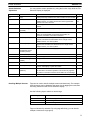
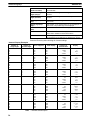
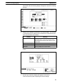
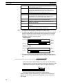
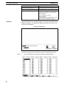
1-2
Using Older Models
The NT Series of Programmable Terminals is constantly being improved to
better serve the needs of our customers. This manual describes features
available for the newest PTs. Not all of these features are available with previous versions of the Host Interface Units and System ROM, as shown in the
following table. Refer to your PT’s operation manuals for details on limitations
when using older models.
2
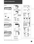
Section 1-3
System Configuration
Host Interface Unit and/or
System ROM
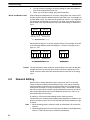
Host Interface Units
NT20M-LK201-EV1
NT20M-LK202-EV1
NT20M-LK203-EV1
NT20M-RT121-EV1
System ROM
NT600M-SMR01-E
Unsupported features
Lamps and touch switches
Lamp flashing for bit input designations
Round lamp displays
3D frame displays for touch switch
Reverse video display for touch switch inputs
Mark input for labels
Bar graphs
Vertical displays
Enlarged display widths (2 to 255 dots)
+/– displays
Enlarged percentage displays
Numeral displays
Enlarged displays
Increased display quantity (50)
Numeral tables
Keypad layout designations
Increased quantity (50)
Stand-alone operation
Backlight red/white color changes and light/flash designations
1-3
System Configuration
The NT20M/NT600M Support Tool is a software package for creating and
maintaining display Screens, memory tables, and custom characters (called
marks) for the NT20M and NT600M Programmable Terminals. The Support
Tool uses a complete system of menus to facilitate operation.
1-3-1
NT20M and NT600M Support Tool Operations
The Support Tool can be used to create and modify screens, memory tables,
and marks, and save resulting data as files. Data created on the Support Tool
can be transmitted to the NT20M or NT600M Programmable Terminal. In addition, the Support Tool can receive data from a Programmable Terminal, or
data created on the Support Tool can be transmitted to a PROM writer. Also,
the Support Tool can receive data from PROM writers. The Support Tool can
read history records stored in a Programmable Terminal, and save them in
files.
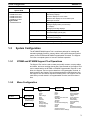
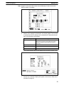
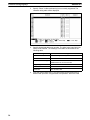
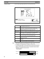
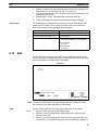
1-3-2
Menu Configuration
Edit Screen
Main Menu
Tool Settings
See page 15 for
specific settings.
Exit
File Selection
Copy
Delete
Print
Title Change
ROM
History
Transmit
Receive
Initial Screen
Change Capacity
Change Title
Tool Settings
Screen
Selection
Copy
Delete
Print
Attributes
Reading from other Files
Table Edit
Transmit
Receive
Continuous/Overlapping
Screens
Check
Marks
Change Comment
Direct Connection Settings
Editing
Input String
Numeral Display
String Display
Lamps
Touch Switches
Bar Graphs
Table Editing
Numeral Editing
Graphics
Marks
Edit
Extended Functions
Environment Settings
3
Section 1-4
Creating a Work Disk
1-3-3
Support Tool System
Model
NT20M-ZA5AT-EV4
System disk
3.5-inch (2DD) and 5-inch (2HD) disks
Applicable computers
IBM PC/AT or IBM PC/AT compatible (note 1)
Floppy disk drives necessary
One min. (note 2)
Graphic monitor
VGA
Printer
Epson dot matrix or HP laser printer
PROM writer
Commercially available PROM writer (note 3)
Mouse
Serial mouse (note 4)
MS-DOS
Version 3.3 or later
Note 1. The computer must have 640 KB of memory.
2. The Support Tool can also use built-in RAM or a hard disk.
3. The following communications settings must be supported. The Intel HEX
file format can be used.
Baud rate:
9,600 bps
Stop bits:
1 bit
Data length:
8 bits
Parity:
None
4. The mouse.com file must be installed before using the Support Tool with a
mouse.
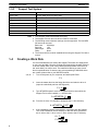
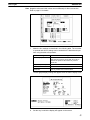
1-4
Creating a Work Disk
It is recommended that you backup the Support Tool either onto floppy disks
or onto your hard disk, store the originals (the floppy disks, hereafter referred
to as the “master disks”) and use the backup disks (hereafter referred to as
the “work disks”) for routine work. The method for backing up onto a hard
disk is explained below. If there are any points pertaining to MS-DOS which
are unclear, please refer to your MS-DOS manual.
1, 2, 3... 1.
Turn on the power to your computer, and start up MS-DOS.
C>
2.
Insert the master disk into the floppy disk drive and switch to drive A.
(Input the underlined part from the keyboard.)
C > A:
3.
Type NTINSTALspaceC:return to designate the drive onto which the
Support Tool is to be installed, i.e., the work disk.
A >NTINSTAL C:
or
From the A: drive, it is possible to designate the C: drive directory.
A >NTINSTAL C:\NT\
4.
If the installation program is successfully completed, then the Support
Tool will be installed in the NT directory on the work disk. Switch from
the A: drive to the C: drive. In the C: drive, switch to the NT directory.
A > C:
C >CD \NT
4
Section 1-6
Main Menu
5.
Input NTMreturn to start and use the Support Tool.
C > NTM
This completes the backup. When starting up the next time, change directories to the NT directory and then input “NTM” to start the Support Tool.
C >CD \NT
C > NTM
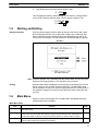
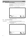
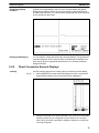
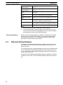
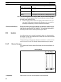
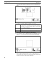
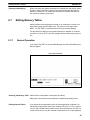
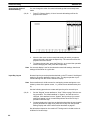
1-5
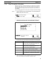
Starting and Exiting
Startup Procedure
If working from a floppy, insert the start-up disk into disk drive A and a data
disk into disk drive B, then turn on the power. When using a hard disk, first
start up MS-DOS from the hard disk, then input NTMreturn from the NT directory. When the Support Tool has started, the following display will appear.
Main Menu
Note While the Support Tool is operating with the system disks, do not pull out the
disks from the floppy disk drive or an operation error will result.
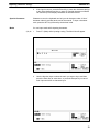
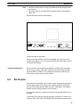
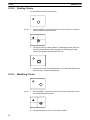
Exiting
1-6
While the Main Menu is displayed, use the Up Key or the Down Key to move
the bar cursor to Exit, and then press the Enter Key. The MS-DOS prompt
will be displayed. At this point, eject the floppy disks and turn off the power to
the computer. Always be sure to follow this procedure when exiting the Support Tool.
Main Menu
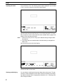
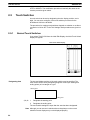
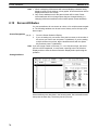
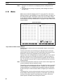
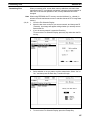
When you start up the Support Tool, the Main Menu will displayed and the
following items will be available.
Main Menu Items
Item
Function
Page
Edit Screen
When you select Edit Screen from the Main Menu, you can manage files and manipulate
and edit screens.
15
Tool Settings
With this item you select the Programmable Terminal, set the memory capacity, specify the
printer to be used, and make other settings. Perform this operation first. The values that you
set here are saved, so there is no need to reset them unless you want to make a change.
11
Exit
Select Exit from the Main Menu when you want to exit the Support Tool. Be sure to exit in
this way when Support Tool operations are finished.
5
5
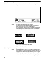
Section 1-7
File Selection
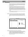
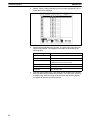
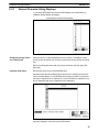
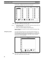
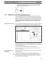
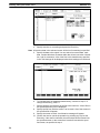
1-7
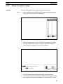
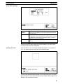
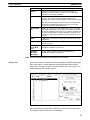
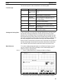
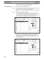
File Selection
When you select Edit Screen from the Main Menu, the File Selection Display
is displayed. Move the bar cursor to the desired file name and press the Enter Key, or click the desired file name once to move the bar cursor and then
again to open the file.
Each file contains screen data, memory table data (for numeral and character string tables), and mark data for a maximum of 250 screens for the
NT20M or 1,000 screens for the NT600M. When you want to create a new
file, select NEW_FILE. The Screen Selection Display will then appear to select from and a file name and title are input when returning to the File Selection Display. Refer to page 10 for name and title input procedures. If you want
to modify a file that has already been created, select the file that you want to
modify.
The help message area will display the direct connection setting and file size
for the file indicated by the bar cursor.
Caution Check the direct connection setting before reading files. If files created with
the direct connection setting turned OFF are read when the Tool Settings is
set to ON, the screens will be converted to direct connection data. It is not
possible to convert from direct connection data to data without direct connection.
File Selection Menu
Caution Data Compatibility with the Old Version of Software (EV1):
The EV4 version of the software can read and edit data created by the EV1.
However, once the data is read by the EV4, it no longer can be read or edited
by the EV1, even if the file name has not been changed. This occurs
because the EV4 expands the data previously saved with the EV1.
Before using any EV1 data with the EV4, it is recommended that a backup
copy of the EV1 be made.
6
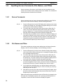
Section 1-8
Screen Selection
File Operations
Function key
You can perform file operations by using the function keys while the File Selection Display is being displayed.
Name
Function
Page
F1
Copy
Copies the contents of one file to another file.
96
F2
Delete
Completely deletes the contents of a file.
97
F3
Print
Prints screen images or data, and cross references of character string and
numeral table usage.
101
F4
ROM
Transmits data from the Support Tool to a PROM writer and receives data
sent from a PROM writer to the Support Tool.
117
F5
History (HIST.)
Receives history records from a Programmable Terminal and saves them
in a file.
98
F6
Transmit
(TMX.)
Transmits screen data from the Support Tool to a Programmable Terminal.
The data can be sent as file units.
106
F7
Receive (RCV.)
Receives screen data sent from a Programmable Terminal to the Support
Tool. The data can be received as file units.
110
F8
Initial Screen
(In. Scr)
Sets the screen number of the first screen to be displayed (the initial
screen) when the Programmable Terminal is powered up or reset.
99
F9
Title Change
(TITLE)
Changes a file title that has previously been set.
98
F10
Next Functions
(NEXT)
Use to change the functions allocated to the function keys.
---
NEXT, F1
Tool Settings
(TOOLS)
Accesses the Tool Settings menu.
15
NEXT, F10
Previous
Functions
(PREV)
Use to change the functions allocated to the function keys.
---
Note 1. The maximum number of files that can be managed by the Support Tool is
254. Any files beyond this number cannot be accessed. If this situation
occurs, use another data directory.
2. The only items displayed on the File Selection Display are the models and
memory capacity that have been set with Tool Settings. For example, if
the NT20M is set as the model and 32 KB is set as the memory, then
NT600M files and 64 KB or 128KB NT20M files will not be displayed. Use
the Memory Capacity Function Key to alter the memory capacity data set
in the file.
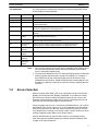
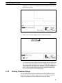
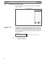
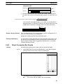
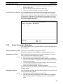
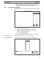
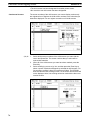
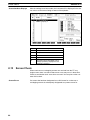
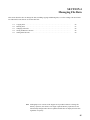
1-8
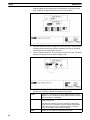
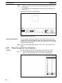
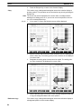
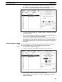
Screen Selection
When you select either NEW_FILE or an existing file from the File Selection
Display, the Screen Selection Display is displayed. If you select an existing
file, the Screen Listing for that file is displayed. Move the bar cursor to the
desired screen and press the Enter Key, or click the desired screen once to
move the bar cursor and then again to edit the screen.
Screen numbers may be from 1 to 250 for the NT20M and from 1 to 1,000 for
the NT600M. Only screen numbers 1 to 16 are displayed on the first display.
Press the Pg Dn Key to see the next display, and the Pg Up Key to see previous display. When creating a new screen, select a screen number for which
nothing is displayed under Status in the Screen Listing.
Screen comments can be input for new screens or for changed screens
when returning from the Edit Display to the Screen Selection Display. Refer
to page 10 for input procedures.
7
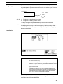
Section 1-8
Screen Selection
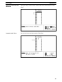
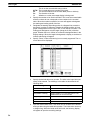
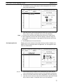
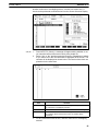
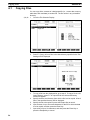
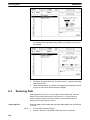
Screen Selection Display
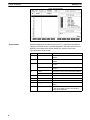
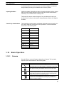
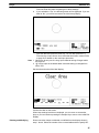
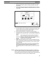
Screen Status
Symbols displayed in the status column (A to E, !) express screen attribute
settings for the each screen. Symbols displayed in the status column are explained in more detail in the Screen Status box, which is in the lower
right-hand corner of the screen.
Symbol
Meaning
(Blank)
No data
Indicates a screen for which no data has been
created.
!
Data exists
Indicates a screen for which data has been
created.
A
A: Cont
Indicates a parent screen for continuous
screens.
A: Ovlp
Indicates a parent screen for overlapping
screens.
B: Buzz
Continuous sound is set as the buzzer attribute.
B: Beep
Intermittent sound is set as the buzzer attribute.
C
C: Err
History attribute is set.
D
D: Bit
Bit input attribute is set.
E
E: Alrm
Alarm attribute is set.
F
F:Keypad
Indicates a keypad has been set for numeral
editing.
G
G:Extend
Indicates that the backlight has been set to red
or that the backlight has been set to flash for
the NT20-DT131/DN131.
B
8
Screen status
Section 1-8
Screen Selection
You can perform screen operations by using the function keys while the File
Selection Display is displayed.
Screen Selection
Operations
Function key
Name
Function
Page
F1
Copy
Copies previously created screen data to another screen number. 90
F2
Delete
Deletes designated screen data. Can also be used to delete
multiple screens, or to delete screens from the Programmable
Terminal one screen at a time.
91,
114
F3
Print
Prints designated screen data. Can also be used to print multiple
screens.
101
F4
Attribute Change
(ATTRIB)
Sets buzzer attributes, bit inputs, history records, and alarms.
78
F5
Read
Loads screen data from other files. The data can include screens, 93
marks, the numeral table, the character string table, I/O
comments, and direct connection information.
F6
Transmit (TMX.)
Transmits data from the Support Tool to a Programmable
Terminal. The data to be transmitted can be a single screen,
multiple screens, or a memory table.
108
F7
Receive (RCV.)
Receives data sent from a Programmable Terminal to the
Support Tool. The data to be received can be a single screen,
multiple screens, or a memory table.
111
F8
Continuous or
Overlapping Screen
Creation (Co/Ovl)
Creates Continuous or Overlapping Screens.
75
F9
Marks (MARK)
Creates and modifies marks.
82
F10
Next Item (NEXT)
Use to change the functions allocated to the function keys.
---
NEXT, F1
Comment Change
(CMNT)
Changes screen comments that have previously been set.
92
NEXT, F2
Table Edit (TABLE)
Edits memory tables
59
NEXT, F3
Check (CHECK)
Checks whether there are any errors in continuous or overlapping 80
screens, and displays or prints the results.
NEXT, F4
Direct Connection
(DIRECT)
Sets data area allocations, comments, and other information for
use with direct connection operation. This function key appears
only if direct connection has been turned ON in the Tool Settings.
17
NEXT, F10
Previous Item (PREV)
Use to change the functions allocated to the function keys.
---
Handling Multiple Screens
Tags can be used to handle multiple screens simultaneously. For example,
several screens can be deleted at the same time by tagging them and then
executing Delete from the Screen Selection Display.
Use the following keys to attach or remove tags.
Key(s)
Operation
Space
Reverses the tag of the screen with the bar cursor.
Home
Clears all tags.
Shift+Home
Reverses all tags.
Tags are indicated by asterisks. By using tags effectively, you can handle
multiple screens as a single group.
9
Inputting Screen Comments, File Names, and Titles
1-9
Section 1-9
Inputting Screen Comments, File Names, and Titles
Screen comments, file names, and file titles can be input whenever new
screens are created or when existing screens are modified. The methods for
inputting these are described in this section.
1-9-1
Screen Comments
Screen comments can be input or changed when shifting from the Edit Display to the Screen Selection Display. Use the following procedure.
1, 2, 3... 1.
1-9-2
Press the Escape Key from the Edit Display after creating a new screen
or editing an existing one. A message will appear asking you to confirm
returning to the Screen Selection Display.
2.
To confirm and to save the new screen data, press the Enter Key. To
return to the Screen Selection Display without saving the new data,
press the Space Key. To cancel returning to the Screen Selection display and continue editing screen data, press the Escape Key.
3.
If the Enter Key is pressed to return to the Screen Selection Display, an
input area will appear for the screen comment. If you have modified an
existing screen, any comment previously input for it will appear. Input or
change the comment as desired (24 characters) and press the Enter
Key. Press the Escape Key to return to step 2.
File Names and Titles
File names and titles can be input when shifting from the Screen Selection
Display to the File Selection Display. Use the following procedure.
1, 2, 3... 1.
Press the Escape Key from the Screen Selection Display after creating
new screens and/or editing existing ones. A message will appear asking
if the new data should be saved.
2.
To confirm and to save the new screen data, press the Enter Key. To
return to the File Selection Display without saving the new data, press
the Space Key. To cancel returning to the File Selection Display and return to the Screen Selection Display, press the Escape Key.
3.
If the Enter Key is pressed to return to the File Selection Display, an input area will appear for the file name. Input the file name (8 characters)
and press the Enter Key. Press the Escape Key to return to step 1.
4.
If you specify an existing file name, you will be asked to confirm overwriting the file. Press the Enter Key to confirm overwriting or press any
other key to return to step 3.
5.
After the file name is input, and input area for the title will appear. Input
the title as desired (28 characters) and press the Enter Key. Press the
Escape Key to return to step 1.
Data will be saved to the specified file when the Enter Key is pressed for the
title input step. The display, however, will not change until the operation is
completed, at which time the File Selection Display will appear.
10
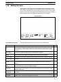
Section 1-10
Editing Screens
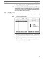
1-10
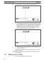
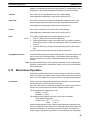
Editing Screens
If you select a screen number from the Screen Selection Display, the Initial
Edit Display will be displayed. If the NT20M has been selected with Tool Settings, then the NT20M screen image display area will be shown in the rectangular box at the top of the display. If the NT600M has been selected, then the
entire display becomes a display area and this box will not appear.
Initial Edit Display
Screen Edit Operations
The following operations can be performed on the Edit Display.
Item
Function
Page
Input string (STR
IN)
Inputs character strings to be displayed on the screen and sets their display positions and
the manner in which they are to be displayed. Character strings input in this way are treated
as fixed displays, and their displays cannot be changed while the Programmable Terminal is
operating.
22
Numeral display
(NUM DISP)
Sets numeric displays for the screen by designating the numeral table entry to be referenced
at the time of display, the display position, and the method of display.
28
String display (STR Sets character string displays for the screen by designating the string table entry to be
DISP)
referenced at the time of display, the display position, and the method of display.
34
Lamps (LAMP)
Sets lamps for the screen by designating the size/shape of lamp areas, numbers, and labels.
40
Touch switches
(TOUCH SW)
Sets touch switches for the screen by designating the size of touch switch areas, numbers,
and labels.
46
Bar graphs (BAR
GRPH)
Sets bar graphs for the screen by designating the numeral table entry to use, the display
positions/directions, and the method of display. The display of percentage calculations is
also set.
51
Table editing (TBL
EDIT)
Edits numeral table and character string table contents, and is the same as the table editing
operation entered from the Screen Selection Display.
59
Numeral editing
(NUM EDIT)
Creates screens for numeric input via function keys, touch switches, or Expansion I/O Units
62
(32/16 Terminals or Function Key Units (12 keys)) and designates the numeral table to which
the input will be written.
Graphic input
(GRAPHIC)
Polylines (a broken line made up of one or more line segments) and circles can be created
on screen.
71
Marks (MARK)
Creates and modifies marks.
82
Edit (EDIT)
Copies, moves, or deletes text or graphics on the screen.
87
11
Section 1-11
Inputting Character Strings and Numbers
Item
Function
Page
Extended
Functions
(EXTEND)
Enables usage of stand-alone operation. In stand-alone operation, screens can be changed
from PT touch switches/function keys or from Expansion I/O Units.
85
Sets data area allocations, comments, and other information for use with direct connection
operation. This function key appears only if direct connection has been turned ON in the Tool
Settings.
19
Set Environment
(SET ENV)
Accesses a modified version of the Tool Settings to enable changing certain Support Tool
operating parameters during operation.
16
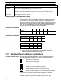
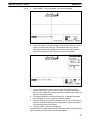
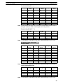
Changing Menu Position and Grid Display
While creating data for the NT600M, there may be times when the screen
data and the menu box overlap, making it difficult to see what you are doing.
In such cases, you cam move or delete the menu box. The grid display can
also be turned ON and OFF for either the NT600M or NT20M by pressing the
Delete Key as long as grid display has been enabled in the tool settings (See
page 15). The display position of the menu box and will change each time
you press the Home Key as shown in the following tables.
NT600M with Grid Enabled
Delete Key
inputs
Initial
1
2
3
4
5
6
Menu
Bottom Top
None
Bottom
Top
None
Bottom
Grid
ON
OFF
OFF
OFF
ON
ON
ON
NT600M with Grid Disabled
Delete Key inputs
Initial
1
2
3
Menu
Bottom
Top
None
Bottom
Grid
OFF
OFF
OFF
OFF
Initial
1
2
Menu
Bottom
Bottom
Bottom
Grid
ON
OFF
ON
NT20M
Delete Key inputs
Note 1. The display position of the menu cannot be changed for the NT20M.
2. Screen data cannot be created and you cannot switch to the Screen
Selection Display unless the menu is displayed.
1-11
Inputting Character Strings and Numbers
Inputting Character Strings
You can use the Left, Right, Backspace, Delete, Insert, and Escape Keys
when inputting character strings. Their functions are described below.
Moves the cursor to the left.
Moves the cursor to the right.
BS
Deletes one character to the left of the cursor.
DEL
Deletes one character at the cursor position.
INS
Switches between insert mode and overwrite mode.
ESC
Cancels character input string and returns to previous operation.
In insert mode, the cursor becomes a flashing rectangle and character
strings are inserted at the cursor position. When text is inserted in this way,
character strings to the right of the cursor position move to the right.
12
Section 1-12
Basic Operation
In overwrite mode, the cursor becomes a reversed rectangle and character
strings delete previously input characters at the cursor position.
Inputting Numbers
Inputting numbers is basically the same as inputting character strings, except
that you cannot change between insert mode and overwrite mode with the
Insert Key. The overwrite mode is always used.
The Home Key can be used to change to 0 any numbers previously input,
and the Minus (–) Key can be used to change between positive and negative
numbers.
Control Key Combinations
The Control Key can be used in combination with other keys to move the cursor, delete characters, and achieve other operations. These combinations
are shown in the following table.
Keys
1-12
1-12-1
Same as
CTRL + S
Left Cursor Key
CTRL + D
Right Cursor Key
CTRL + E
Up Cursor Key
CTRL + X
Down Cursor Key
CTRL + R
Page Up Key
CTRL + C
Page Down Key
CTRL + H
Backspace Key
CTRL + G
Delete Key
CTRL + I
Tab Key
CTRL + M
Enter Key
CTRL + [
Escape Key
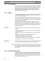
Basic Operation
Cursors
Several different cursors will appear depending on Support Tool operation.
Special cursors are described in the following table.
Cursor
Meaning
The arrow cursor is used in combination with the cursor to specify
menu items and icons. Refer to page 14 for details on the mouse.
A cup will appear when the Support Tool is accessing data on the
disk. When accessing has finished, the arrow cursor will return.
A question mark will appear when the Support Tool is waiting for
a Yes/No response from the user. Press the Enter Key or the left
mouse button to answer Yes (confirm) or press the Escape Key
or right mouse button to answer No (cancel).
A hand and keyboard will appear at the end of processing to
request user acknowledgement. Press any key or either mouse
button to continue operation.
13
Section 1-12
Basic Operation
1-12-2
Screen Buttons
There are many buttons in the shape of keys that can appear during Support
Tool operation. These buttons can be clicked with the mouse to achieve the
same operation as the equivalent keyboard keys. Included are the Enter Key
(carriage return arrow), Escape Key, cursor keys, PgUp Key, PgDn Key,
Space Bar, Shift+Home (clear) Key (one button combining two keys), the
Home (clear) Key, and function keys.
1-12-3
Mouse
A mouse can be connected to the Support Tool and used to input coordinates
to specify display positions for text strings or numerals and to create polylines, circles, and other graphics.
To use a mouse, connect a two-button mouse to the computer’s mouse connector and prepare a level, smooth surface, such as a mouse pad, to operate
it on. The mouse can then be used to move labels, the + cursor, and other
objects on the screen (see below).
Procedures in this manual are generally written for operation from the keyboard. There are, however, often three means to execute an operation, i.e.,
from the keyboard, using on-screen buttons, and using the mouse and cursor
directly. It is generally a matter of preference on which method is used; the
results will be the same.
Left Button
The left mouse button can be used in place of the Enter Key to achieve the
following.
• To specify items on menus. Click the mouse once to move the cursor and
then again to execute.
• To click on-screen buttons to replace keyboard key inputs. See page 14 for
details.
• Double-clicking to end polyline input (instead of Shift + Enter).
• Dragging to move objects on screen or draw lines.
• To designate display positions for text or numerals
• To designate display positions for touch switches, lamps, and bar graphs
• To designate center, start, and end points for graphics
Right Button
The right mouse button can be clicked in place of pressing the Escape Key to
move backward through processing steps or to cancel an operation.
Caution Although either the mouse or the keyboard can be used for most operations,
some operations have been restricted to only keyboard operation for safety. If
the software does not respond when a mouse button is pressed, use the keyboard instead.
1-12-4
Positioning Operations
Grid display can be set via the Tool Settings, and grid display and snap-togrid operation can be set via the Set Environment settings. The grid can be
used either to visually align objects on the display or it can be combined with
snap-to-grid operation to force objects to be positioned exactly on the grid.
Refer to pages 15 and 16 for details.
14
Section 1-13
Tool Settings
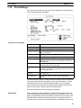
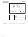
1-13
Tool Settings
If you start up the Support Tool and select Tool Settings from the Main Menu,
the Tool Settings Display will appear.
Contents of Tool Settings
Name
Content
NT Model
Sets the model of Programmable Terminal being used.
Memory Size
Sets the memory capacity of the Programmable Terminal.
Direct Setting
Turns ON and OFF the direct connection operation. Refer to
page 17 for details.
Printer
Sets the printer model to be used.
Sheet Feeder
Sets a sheet feeder for the printer.
Auto Refresh
Sets whether or not the screen will be automatically
refreshed when you make screen data additions, deletions,
or modifications.
Display Grid
Controls the grid display. If “TouchSW” is specified, each grid
unit will be the size of a touch switch.
Communication
Port
Specify the port on the computer to be used to communicate
with the PT. If possible, do not specify the same port as the
one used for the mouse.
Temporary
Directory
Sets the file name for the work file that is temporarily used by
the Support Tool.
Data Directory
Sets directory names for saving screen data which is
created.
Press the Enter Key when you want to save the contents of the Tool Settings.
Then either press the Enter Key again to return to the Main Menu, or press
the Escape Key to return to the Tool Settings Display to correct settings.
If you press the Space Key, the tool settings will be changed without being
saved to a file, and you will be returned to the Main Menu.
Press the Escape Key to cancel changing tool settings.
Auto Refresh
When screen data is added, deleted, or modified with the Support Tool, the
screen display may be temporarily disordered. If Auto Refresh is set to “Yes,”
then the screen display will be automatically rewritten when you return to the
Initial Edit Screen. When creating large amounts of screen data, however,
some time may be required for screen refreshing. Auto Refresh can be set to
15
Section 1-14
Environment Settings
“No” to save time. You can manually rewrite the screen by pressing the Tab
Key during operation.
Temporary Directory
The Support Tool will create a temporary work file when creating screens or
transferring data to or from ROM. Most write operations are performed on
this temporary file. To increase overall operating speed, this file should be
created on your hard disk or in RAM.
Tool Settings File
File settings are saved in the root directory for the Support Tool, i.e., the directory from which the Support Tool is started. The file name is
NTMSET.ENV. If this file exists in the root directory when the Support Tool is
started, the setting in the file will be read and the Support Tool will operate
according to them. Tool settings files can be used to eliminate the need to
reset tool setting each time the Support Tool is started.
Display Grid
A grid can be displayed to aid in positioning objects when creating screens.
The Tool Settings can be used to disable the grid or to set its size to 8, 16, or
32 dots. The grid size can also be set to the same size as a touch switch by
specifying “TouchSW.” The grid, once enabled, can be turned ON or OFF as
desired during operation. Refer to page 12 for details.
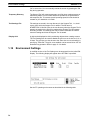
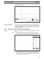
1-14
Environment Settings
A modified version of the Tool Settings can be accessed from the Initial Edit
Display. The following display will appear when SET ENV is specified.
Set the PT operating environment as described in the following table.
16
Section 1-15
Direct Connection
Item
Display
y grid
g
Snap ON
function
Lamp/touch
switch number
di l
display
Settings
Setting
No
Display grid is not displayed.
8-dot
16-dot
32-dot
Display grid is displayed at the specified width. Screen
objects can be snapped to the grid if one of these
settings is made and the snap ON function is turned
ON (see below).
Touch
switch
Display grid is displayed at the minimum width for
touch switches. This setting is useful to draw lamps to
the same size as touch switches. It functions the same
way as the other grids.
Off
Allows graphics to be drawn and screen objects to be
positioned without interference from the grid, i.e., the
grid, if displayed, is used only as a visual guide.
On
Allows graphics to be drawn and screen object to be
positioned only to the intersection points of the grid.
No
Lamp/touch switch numbers or bit addresses are not
displayed.
1/16
1/4
Indicates lamp/touch switch specifications and the
allocated lamp/touch switch number or the allocated
PC bit on the display at the specified character size.
For example, “LH001015” would be displayed for a
lamp display allocated to HR 1015 using direction
connection, “TA001012”would be displayed for a touch
switch display allocated to AR 1012 using direction
connection, L000 would be displayed for lamp #0 when
not using direction connection, and T010 would be
displayed for touch switch #10.
Memoryy table
entry
t number
b
display
1-15
No
Memory table entry numbers are not displayed.
1/16
1/4
Indicates the allocated memory table number on the
display at the specified character size for numeral
displays, character string displays, bar graphs, and
numeral editing areas. “N” is also displayed for
numeral table entry numbers and “S” is displayed for
character string table entry numbers.
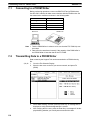
Direct Connection
The PT can be set for direct connection to an OMRON PC to allow numeral
displays, character displays, numeral editing, lamps, touch switches, and bar
graphs to be directly connected to specific bits and words in PC memory. Bits
can also be set that will change the displayed screen. This is possible only
when the NT600M-DT121/DT211 or NT20M-DT121-V1/DT131 PTs and only
when a NT600M-LK201 SYSMAC WAY Host Interface Unit is used. Also,
either an NT600M-SMR31 or NT20M-SMR31 System ROM must be used in
the PT.
The direct connection setting in the Tool Settings greatly affects the operation
of the screen functions that read or write PC memory. Although using direction connection will greatly reduce programming burden for the PC, careful
preparation is required to coordinate PC memory and programming with the
PT settings for direct connection. The general procedure for this is as follows:
1, 2, 3... 1.
2.
3.
Design the required PT screens.
Allocate PC memory to the function elements of the screens, i.e., those
elements that will directly read or write PC memory. Be sure to list specific PC memory addresses, including areas, and to consider numeral
table and character string table capacities.
Turn ON direct connection operation in the Tool Settings.
17
Section 1-15
Direct Connection
4.
5.
6.
Create the required screens, making all settings required for direct connection.
Save the screens.
Transfer the screens to the PT or write them to ROM.
Conversion
Screen files that were created with direct connection turned OFF can be
loaded with direct connection turned ON to convert the screens for use with
direct connection. Once files are created for or converted to direct connection, they cannot be loaded with direct connection turned OFF in the Tool
Settings and cannot be converted back for use without direct connection.
Indication on Displays
Displays on the File Selection Display and the Screen Selection display will
indicate whether or not direct connection has been set. If direct connection
has been set, “-O” (for OMRON) will be added after the PT model name following the “File List” title on the File Selection Display. The help message
area on the Screen Selection Display will also indicate whether or not direct
connection has been used together with the file size.
1-15-1
Specifying PC Addresses for Direct Connection
The function keys are allocated as shown in the following table when specifying bit and word addresses in PC memory. The values in parentheses indicate the maximum word address possible for the largest PC memory. Actual
memory sizes vary, however, with the model of PC. Refer to your PC’s operation manual for specific limits.
Key
Area
F1
AR (511)
F2
HR (99)
F3
LR (63)
F4
DM (9999)
F5
CNT (1023)
F6
TIM (1023)
F7
CIO, IR, SR (2555) (displayed as
I/S)
Home
None
The areas that can be designated for direct connection are as shown in the
following table.
Item
Lamps
Memory unit
Bit
Designation
IR, SR (CIO), AR, or LR bit addresses.
DM word address can also be designated with
bit specifications.
specifications
Touch switches
Numeral display
Bar graphs
Numeral editing
Character string
display
Timers and counters cannot be designated.
(See note.)
Word
IR, SR (CIO),
(
) AR, LR, or DM word addresses.
Timer and counter numbers can also be
specified to designate PVs
PVs.
IR, SR (CIO), AR, LR, or DM word addresses.
Timer and counter numbers cannot be
specified.
Note If touch switches are set to write to bits in the DM area (notify bits), the touch
switch will control the status of the specified bit and all other bits in the specified word will be turned OFF (0).
18
Section 1-15
Direct Connection
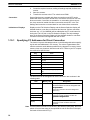
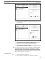
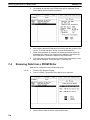
1-15-2
Direct Connection Information
Settings for the direct connection information are made from the extended
functions display. Direct connection information settings will not appear on
the extended function display unless direct connection is turned ON in the
Tool Settings.
Use the following procedure to set the direct connection information settings.
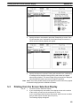
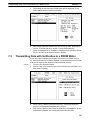
1, 2, 3... 1.
Specify EXTEND from the Initial Edit Display. The following display will
appear at the bottom of the screen
2.
Specify direct connection. (F-key is not supported by PTs with touch
panels and cannot be specified.) The following display will appear.
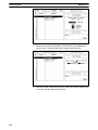
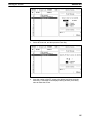
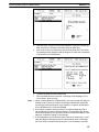
3.
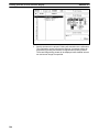
Set the direct connection information as described in the following table.
Item
Setting
PT control area
Set the address of the first word in the PC to be used to
control PT status. This setting must be made. A user
comment may also be input if desired.
PT notify area
Set the address of the first word in the PC to be used to
store PT status. This setting must be made. A user
comment may also be input if desired.
Numeral mem. table
The contents of the numeral table used in the file can be
seen in list form. Data can be input or changed.
String mem. table
The contents of the character string table used in the file
can be seen in list form. Data can be input or changed.
F-key input/output notify
Function keys cannot be set for PTs with touch panels.
These settings are not required and will be ignored if
input.
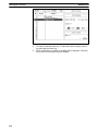
4.
When the settings have been completed, press the Escape Key once to
return to the beginning of the operation and twice to end.
19
SECTION 2
Creating Screens
This section describes the procedures used to create and check screens and to input screen attributes. The procedures for
creating special display characters, called marks, and for controlling screens during stand-alone operation are also provided here.
2-1
2-2
2-3
2-4
2-5
2-6
2-7
2-8
2-9
2-10
2-11
2-12
2-13
2-14
2-15
2-16
Inputting Character Strings . . . . . . . . . . . . . . . . . . . . . . . . . . . . . . . . . . . . . . . . . . . . . . . . .
2-1-1 New Character Strings . . . . . . . . . . . . . . . . . . . . . . . . . . . . . . . . . . . . . . . . . . . . . .
2-1-2 Deleting Character Strings . . . . . . . . . . . . . . . . . . . . . . . . . . . . . . . . . . . . . . . . . . .
2-1-3 Modifying Character Strings . . . . . . . . . . . . . . . . . . . . . . . . . . . . . . . . . . . . . . . . .
Numeral Displays . . . . . . . . . . . . . . . . . . . . . . . . . . . . . . . . . . . . . . . . . . . . . . . . . . . . . . . . .
2-2-1 Normal Numeral Displays . . . . . . . . . . . . . . . . . . . . . . . . . . . . . . . . . . . . . . . . . . .
2-2-2 Direct Connection Numeral Displays . . . . . . . . . . . . . . . . . . . . . . . . . . . . . . . . . .
Character String Displays . . . . . . . . . . . . . . . . . . . . . . . . . . . . . . . . . . . . . . . . . . . . . . . . . . .
2-3-1 Normal Character String Displays . . . . . . . . . . . . . . . . . . . . . . . . . . . . . . . . . . . . .
2-3-2 Direct Connection Character String Displays . . . . . . . . . . . . . . . . . . . . . . . . . . . .
Lamps . . . . . . . . . . . . . . . . . . . . . . . . . . . . . . . . . . . . . . . . . . . . . . . . . . . . . . . . . . . . . . . . . .
2-4-1 Normal Lamps . . . . . . . . . . . . . . . . . . . . . . . . . . . . . . . . . . . . . . . . . . . . . . . . . . . .
2-4-2 Direct Connection Lamps . . . . . . . . . . . . . . . . . . . . . . . . . . . . . . . . . . . . . . . . . . .
Touch Switches . . . . . . . . . . . . . . . . . . . . . . . . . . . . . . . . . . . . . . . . . . . . . . . . . . . . . . . . . .
2-5-1 Normal Touch Switches . . . . . . . . . . . . . . . . . . . . . . . . . . . . . . . . . . . . . . . . . . . . .
2-5-2 Direct Connection Touch Switches . . . . . . . . . . . . . . . . . . . . . . . . . . . . . . . . . . . .
Bar Graphs . . . . . . . . . . . . . . . . . . . . . . . . . . . . . . . . . . . . . . . . . . . . . . . . . . . . . . . . . . . . . .
2-6-1 Creating Normal Bar Graphs . . . . . . . . . . . . . . . . . . . . . . . . . . . . . . . . . . . . . . . . .
2-6-2 Direct Connection Bar Graphs . . . . . . . . . . . . . . . . . . . . . . . . . . . . . . . . . . . . . . . .
Editing Memory Tables . . . . . . . . . . . . . . . . . . . . . . . . . . . . . . . . . . . . . . . . . . . . . . . . . . . .
2-7-1 Normal Operation . . . . . . . . . . . . . . . . . . . . . . . . . . . . . . . . . . . . . . . . . . . . . . . . .
2-7-2 Direction Connection Operation . . . . . . . . . . . . . . . . . . . . . . . . . . . . . . . . . . . . . .
Numeral Editing . . . . . . . . . . . . . . . . . . . . . . . . . . . . . . . . . . . . . . . . . . . . . . . . . . . . . . . . . .
2-8-1 Normal Numeral Editing . . . . . . . . . . . . . . . . . . . . . . . . . . . . . . . . . . . . . . . . . . . .
2-8-2 Direct Connection Numeral Editing . . . . . . . . . . . . . . . . . . . . . . . . . . . . . . . . . . .
2-8-3 Precautions for Numeral Editing . . . . . . . . . . . . . . . . . . . . . . . . . . . . . . . . . . . . . .
Polylines . . . . . . . . . . . . . . . . . . . . . . . . . . . . . . . . . . . . . . . . . . . . . . . . . . . . . . . . . . . . . . . .
2-9-1 Creating New Polylines . . . . . . . . . . . . . . . . . . . . . . . . . . . . . . . . . . . . . . . . . . . . .
2-9-2 Deleting Polylines . . . . . . . . . . . . . . . . . . . . . . . . . . . . . . . . . . . . . . . . . . . . . . . . .
2-9-3 Modifying Polylines . . . . . . . . . . . . . . . . . . . . . . . . . . . . . . . . . . . . . . . . . . . . . . .
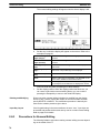
Circles . . . . . . . . . . . . . . . . . . . . . . . . . . . . . . . . . . . . . . . . . . . . . . . . . . . . . . . . . . . . . . . . . .
2-10-1 Creating New Circles . . . . . . . . . . . . . . . . . . . . . . . . . . . . . . . . . . . . . . . . . . . . . . .
2-10-2 Deleting Circles . . . . . . . . . . . . . . . . . . . . . . . . . . . . . . . . . . . . . . . . . . . . . . . . . . .
2-10-3 Modifying Circles . . . . . . . . . . . . . . . . . . . . . . . . . . . . . . . . . . . . . . . . . . . . . . . . .
Continuous and Overlapping Screens . . . . . . . . . . . . . . . . . . . . . . . . . . . . . . . . . . . . . . . . .
Screen Attributes . . . . . . . . . . . . . . . . . . . . . . . . . . . . . . . . . . . . . . . . . . . . . . . . . . . . . . . . .
Screen Check . . . . . . . . . . . . . . . . . . . . . . . . . . . . . . . . . . . . . . . . . . . . . . . . . . . . . . . . . . . .
Marks . . . . . . . . . . . . . . . . . . . . . . . . . . . . . . . . . . . . . . . . . . . . . . . . . . . . . . . . . . . . . . . . . .
Stand-alone Operation . . . . . . . . . . . . . . . . . . . . . . . . . . . . . . . . . . . . . . . . . . . . . . . . . . . . .
Edit . . . . . . . . . . . . . . . . . . . . . . . . . . . . . . . . . . . . . . . . . . . . . . . . . . . . . . . . . . . . . . . . . . . .
22
22
25
26
28
28
31
34
35
37
40
40
43
46
46
48
51
52
55
59
59
61
62
63
68
70
71
71
72
72
73
73
74
74
75
78
80
82
85
87
21
Section 2-1
Inputting Character Strings
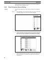
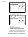
2-1
Inputting Character Strings
With the Character Input Display, you set characters to be displayed on the
PT. You set character sizes, character scaling factors, manner of display, and
display positions.
If you select STR IN from the Initial Edit Display, the Initial Character Input
Display will appear.
Initial Character Input Display
The following pages explain how to use this display, taking the creation of
NT20M screen data as an example.
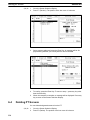
2-1-1
New Character Strings
Inputting Strings
This example shows how to input the roman letters “abcde.”
You can display up to 32 characters per line on a NT20M screen, and up to
80 per line on a NT600M screen.
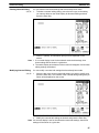
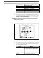
1, 2, 3... 1. Specify CREATE.
2. Input the characters, e.g., “abcde.” The following display will appear.
22
Section 2-1
Inputting Character Strings
3.
If the input is correct, press the Enter Key to enter the characters and go
to the String Attributes section on page 24. Special characters or Marks
can also be input as display characters as described below.
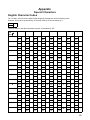
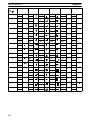
Special Characters
Characters not on the keyboard can be input via character codes. A list of
character codes is provided at the end of the manual. To input a character
code, press the ALT Key followed by the decimal code.
Marks
You can input marks while inputting characters.
1, 2, 3... 1.
2.
Press F1 (Mark) while inputting a string. The Mark List will appear.
Use the direction keys to select the mark you want to input, and then
press the Enter Key to enter them, or press the Escape Key to cancel
mark input and return to character input.
23
Section 2-1
Inputting Character Strings
String Attributes
Here you set the size, scale, and attributes for character strings that have
been input.
1, 2, 3... 1.
2.
3.
Set the size to be used for each 1-byte character.
Set the scale factor for the characters. NT600M strings can be set to
64X in addition to the ones shown in the above display.
Set display attributes. “Spot” is for flashing characters in reverse video.
Display attributes will be displayed on the computer screen as shown
below. (Although the contrast of most displays in this manual is reversed, the contrast of these examples is the same of that on the
screen.
Normal
Inverse
4.
Flashing
Spot (Inverse Blinking)
Press the Enter Key after checking the settings.
A display for designating string position will appear next.
Designating Display
Position
24
Designate the display position for the string.
1, 2, 3... 1.
A rectangular guide box showing the size of the input character string
will be displayed. The guide box is displayed according to the number of
characters input to that point, and the scale which has been set. Set the
display position on the screen with the direction keys. By operating the
direction keys while pressing the Shift Key, you can move the guide box
16 dots at a time. The X and Y coordinates of the display position (the X
and Y coordinates of the lower left-hand corner of the guide box) are
Section 2-1
Inputting Character Strings
displayed. You cannot set a display position that allows the guide box to
extend off the screen.
Guide box
Cross-shaped cursor
2-1-2
2.
When you have set the display position, press the Enter Key.
3.
You will be returned to the Initial Text Input Display, and the contents set
up to this point are displayed. At this time, a message again appears in
the command box instructing you to enter text. If you are inputting text to
different places on the same screen, repeat the operations described
above. When you have finished inputting text, press the Escape Key.
You will be returned to the Initial Edit Display.
Deleting Character Strings
You can delete strings that have already been set by using the procedure
given below. When you delete a string, a portion of the display may be left
empty. If this happens, press the TAB Key to rewrite the display.
25
Section 2-1
Inputting Character Strings
1, 2, 3... 1.
Specify DELETE. The cross-shaped cursor will be displayed.
2.
Line up the center of the cross-shaped cursor with the string you want to
delete, and press the Enter Key. The string which you have selected will
be outlined by a guide box. A message will appear in a comment box to
verify whether you actually want to delete that string. If a number of
characters have been input at one time, then it makes no difference
which character you place the cross-shaped cursor on.
3.
To delete the string, press the Enter Key, or to cancel, press any key
other than the Enter Key.
The basic delete operation for other data on the Edit Display, e.g., numeral
displays, is the same.
Note If the screen is not properly displayed after deleting, press the Tab Key to
rescan the display.
2-1-3
Modifying Character Strings
You can modify strings that have already been set.
26
Section 2-1
Inputting Character Strings
1, 2, 3... 1.
Press MODIFY. The cross-shaped cursor will be displayed.
2.
Line up the center of the cross-shaped cursor with the string you want to
change, and press the Enter Key. The character which you have selected will be outlined by a guide box, and at the right of the screen a
box will be displayed for you to select the items to be modified.
3.
Use the Up and Down Keys to select the item to modified, and then
press the Enter Key. You can return to step 2 by pressing the Escape
Key. For items selected for change, data input methods are the same as
when the string was created.
To end the modification, press the Escape Key. A message will appear
asking whether you want to save the modified contents.
Press the Enter Key to save any changes made, or if you do not wish to
save the modified contents, press the Space Key to cancel all modifications and restore the previous data.
To return to step 3, press the Escape Key.
4.
5.
6.
The procedure for modifying data with the Edit Display is the same as that for
other functions such as numeral and character displays.
27
Section 2-2
Numeral Displays
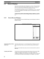
2-2
Numeral Displays
Values from numeral tables can be displayed on a screen. The numeral table
entry to be referenced, the display position, and the manner of display are
set. You can set a maximum of 50 numeral displays per screen.
For the NT20M, numeral table entries are numbered from 0 to 127, for a total
of 128. For the NT600M, numeral table entries are numbered from 0 to 255,
for a total of 256.
The procedure for setting number displays depends on whether or not direct
connection is ON or OFF in the Tool Settings. Both procedures are given below.
2-2-1
Normal Numeral Displays
Select NUM DISP from the Initial Edit Display, the Initial Display for Numeral
Display will appear.
Initial Display for Numeral Display
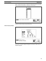
Designating Numeral Table
References
Only table number entries 0 to 13 are displayed first. To display the next entries, press the Pg Dn Key; to return to previous entires, press the Pg Up
Key.
Select the numeral table entry that you want to reference and then press the
Enter Key.
Inputting Initial Values
28
The initial value for the selected memory table reference is input next. Refer
to page 12 for details on input methods. You can input numbers from
–99999999 to 99999999. Numeral displays can display decimal numbers, but
you enter them here without the decimal point. For example, if you want to
Section 2-2
Numeral Displays
input –123.456, then just input –123456. The distinction between the integer
portion and the decimal portion is specified in the next step.
Input the number, and then press the Enter Key.
Numeral Display Settings
Set the way in which the display will appear on the screen. Refer to the examples on page 30.
29
Section 2-2
Numeral Displays
Reference table entry
(Reference Table)
Set the number of the item to be referenced in the
numeral table.
Number of integer
digits (Integer)
Set the number of digits for the integer portion of the
number.
Number of decimal
digits (Decimal)
Set the number of digits for the decimal portion of the
number.
Zero suppress (Zero
Sup)
Set whether or not leading zeros are to be displayed on
the screen.
Display sign (Disp
Sign)
Set whether or not negative signs are to be displayed on
the screen. The positive sign is not displayed.
Character size (Char
Size)
Set the size of characters to be displayed on the screen.
Scale
Set the scale factor for the display. The NT600M can be
set to 64X in addition to those shown above.
Attributes
Sets display attributes for the screen. Refer to page 24
for examples of how attributes are displayed on screen.
Press the Enter Key after checking all of these settings.
Numeral Display Examples
Number of
integer digits
Number of
decimal digits
Zero suppress
Code display
Contents of
numeral table
Display
3
3
3
3
0
0
0
0
No
No
No
No
No
No
No
No
12
1234
–12
–1234
012
***
012
***
3
3
3
3
0
0
0
0
No
No
No
No
Yes
Yes
Yes
Yes
12
1234
–12
–1234
_012
****
–012
****
3
3
3
3
0
0
0
0
Yes
Yes
Yes
Yes
No
No
No
No
12
1234
–12
–1234
_12
***
_12
***
3
3
3
3
0
0
0
0
Yes
Yes
Yes
Yes
Yes
Yes
Yes
Yes
12
1234
–12
–1234
__12
****
_–12
****
2
2
2
2
2
1
1
1
1
1
No
No
No
No
No
No
No
No
No
No
1
12
1234
–12
–1234
00.1
01.2
****
01.2
****
2
2
2
2
2
1
1
1
1
1
No
No
No
No
No
Yes
Yes
Yes
Yes
Yes
1
12
1234
–12
–1234
_00.1
_01.2
*****
–01.2
*****
2
2
2
2
2
1
1
1
1
1
Yes
Yes
Yes
Yes
Yes
No
No
No
No
No
1
12
1234
–12
–1234
_0.1
_1.2
****
_1.2
****
2
2
2
2
2
1
1
1
1
1
Yes
Yes
Yes
Yes
Yes
Yes
Yes
Yes
Yes
Yes
1
12
1234
–12
–1234
__0.1
__1.2
*****
_–1.2
*****
Note _ indicates a blank space.
30
Section 2-2
Numeral Displays
Designating Display
Positions
A guide box corresponding to the size of the numeral display will appear.
Designate the display position on the screen with the cross-shaped cursor
and press the Enter Key. You cannot make a setting that will cause the guide
box to extend from the screen.
Deleting and Modifying
You can delete or modify previously input numeral displays. The procedures
for these operations are the same as those for deleting and modifying character strings. Refer to appropriate subsections of 2-1 Inputting Character
Strings for details.
2-2-2
Creating
Direct Connection Numeral Displays
Use the following procedure to create a direct connection numeral display.
1, 2, 3... 1.
2.
Select NUM DISP from the Initial Edit Display, a list of the numeral displays already existing in the current screen will be displayed.
Specify the number to be used in the table. This is not the numeral table
and the numbers do not correspond to item numbers in the numeral
table. When a number is specified, a display to set direct or indirect referencing will appear.
31
Section 2-2
Numeral Displays
3.
Specify “Direct.” Indirect referencing is not currently supported. The numeral table will be displayed.
4.
Specify the desired table entry number. The initial value input field (contents) will be entered. The headings in the table are described in the
following table.
Heading
5.
32
Meaning
No.
Numeral table entry number
Contents
Initial value
IN initialize at startup)
Indicates whether or not the table value is to be
initialized when the PT is turned ON.
# (quantity)
Number of PC words used
Word
Address of the first PC word
Comment
User comment area
Input the desired initial value. This value can be omitted here if desired
and input later using the table edit operation. The initial value can be up
to 8 digits long. When the initial value field is left, the following display
will appear to input the remaining settings.
Section 2-2
Numeral Displays
Note Negative values and initial values are set differently for direct connection.
Refer to page 61 for details.
6.
Make the four settings as described in the following table. The comment
is optional and all four settings can be omitted here if desired and input
later using the table edit operation.
Heading
Meaning
Initialize (Init)
Set YES to initialize the contents in the numeral
table when PT power is turned ON. Set to NO to
maintain the previous value when PT power is
turned ON.
Set words (St Word)
Set the number of PC words to be used.
Word
Set the address of the first PC word to be used.
Comment
Input any desired user comment area
The numeral display settings will appear when the above display is left.
7.
Set the way in which the display will appear on the screen. Refer to the
examples on page 30.
33
Section 2-3
Character String Displays
Number of integer
digits (Integer)
Set the number of digits for the integer portion of the
number.
Number of decimal
digits (Decimal)
Set the number of digits for the decimal portion of the
number.
Zero suppress (Zero
Sup)
Set whether or not leading zeros are to be displayed on
the screen.
Display sign (Disp
Sign)
Set whether or not negative signs are to be displayed on
the screen. The positive sign is not displayed.
Character size (Char
Size)
Set the size of characters to be displayed on the screen.
Scale
Set the scale factor for the display. The NT600M can be
set to 64X in addition to those shown above.
Attributes
Sets display attributes for the screen. Refer to page 24
for examples of how attributes are displayed on screen.
Display type (Disp
Type)
Specify either decimal or hexadecimal display.
8.
Deleting and Modifying
2-3
Press the Enter Key after completing all of these settings.
Set the display position. When the display position has been set, you
can return to set another numeral display or you can continue pressing
the Escape Key to return to the Initial Edit Display.
Direct connection numeral displays are deleted or modified from the display
shown in step 1. above. Select the number of the numeral table and then
specify DELETE or MODIFY. The modification procedure is basically the
same as the creation procedure given above.
Character String Displays
The contents of character string tables can be displayed on the screen. The
string table entry to be referenced, the display position, and manner of display must be set.
You can set a maximum of 8 string displays per screen for the NT20M and 50
for the NT600M.For the NT20M, string table entries are numbered from 0 to
31, for a total of 32. For the NT600M, string table entries are numbered from
0 to 255, for a total of 256.
The procedure for setting number displays depends on whether or not direct
connection is ON or OFF in the Tool Settings. Both procedures are given below.
34
Section 2-3
Character String Displays
2-3-1
Normal Character String Displays
If you select STR DISP from the Initial Edit Display, the Initial Screen for
Character String Display will appear.
Initial Display for Character String Display
Designating String Tables
to be Referenced
Table entires 0 to 13 are displayed first on the screen. To display the next
entires, press the Pg Dn Key; to return to previously entries, press the Pg Up
Key.
Select the string table entry that you want to reference and then press the
Enter Key.
Inputting Initial Value
Set the initial value for the selected table entry.
Input the initial value according to the instructions for inputting the initial values for numeral tables. For the NT20M, the maximum number of characters
that can be registered is 32 characters. For the NT600M, the maximum number of characters that can be registered is 40 characters.
Input the characters, and then press the Enter Key.
35
Section 2-3
Character String Displays
Setting Display Attributes
Set the way in which the display will appear on the screen.
Number of character
digits (Char; See Note)
Set the number of character digits to be displayed on
the screen.
Character size (Size)
Set the character size to be used for each 1-byte
characters.
Scale
Set the scale for characters to be displayed on the
screen. The NT600M can be set to 64X in addition to
those shown above.
Display attributes
(Attr.)
Set display attributes for the screen. Refer to page 24
for examples of how attributes are displayed on screen.
Note For contents registered in the memory table, only the number of digits that
have been set will be displayed. Each normal character requires one digit
and each mark requires 2 digits.
Press the Enter Key after checking all of the settings.
Designating Display
Position
36
A guide box corresponding to the size of the set contents will be displayed.
Designate the display position on the screen with the cross-shaped cursor
Section 2-3
Character String Displays
and press the Enter Key. You cannot make a setting that will cause the guide
box to extend from the screen.
Deleting and Modifying
2-3-2
Creating
You can delete or modify previously input character string displays. The procedures for these operations are the same as those for deleting and modifying character strings. Refer to appropriate subsections of 2-1 Inputting Character Strings for details.
Direct Connection Character String Displays
Use the following procedure to create a direct connection character string
display.
1, 2, 3... 1.
2.
Select STR DISP from the Initial Edit Display, a list of the character
string displays already existing in the current screen will be displayed.
Specify the number to be used in the table. This is not the character
string table and the numbers do not correspond to item numbers in the
character string table. When a number is specified, a display to set direct or indirect referencing will appear.
37
Section 2-3
Character String Displays
3.
Specify “Direct.” Indirect referencing is not currently supported. The
character string table will be displayed.
4.
Specify the desired table entry number. The initial value input field (contents) will be entered. The headings in the table are described in the
following table.
Heading
5.
38
Meaning
No.
Character string table entry number
Contents
Initial value
IN (initialize at startup)
Indicates whether or not the table value is to be
initialized when the PT is turned ON.
# (quantity)
Number of PC words used
Word
Address of the first PC word
Comment
User comment area
Input the desired initial string. The initial string can be omitted here if
desired and input later using the table edit operation. When the initial
Section 2-3
Character String Displays
value field is left, the following display will appear to input the remaining
settings.
6.
Make the four settings as described in the following table. The comment
is optional and all four settings can be omitted here if desired and input
later using the table edit operation.
Heading
Meaning
Initialize (Init)
Set YES to initialize the contents in the character
string table when PT power is turned ON. Set to
NO to maintain the previous value when PT power
is turned ON.
Set words (St Word)
Set the number of PC words to be used.
Word
Set the address of the first PC word to be used.
Comment
Input any desired user comment area
The character string display settings will appear when the above display
is left.
7.
Set the way in which the display will appear on the screen.
Press the Enter Key after completing all of these settings.
39
Section 2-4
Lamps
Number of character
digits (Char; See Note)
Set the number of character digits to be displayed on
the screen.
Character size (Size)
Set the character size to be used for each 1-byte
characters.
Scale
Set the scale for characters to be displayed on the
screen.
Display attributes
(Attr.)
Set display attributes for the screen. Refer to page 24
for examples of how attributes are displayed on screen.
Note For contents registered in the memory table, only the number of digits that
have been set will be displayed. Each normal character requires one digit
and each mark requires 2 digits.
8.
Deleting and Modifying
2-4
Set the display position. When the display position has been set, you
can return to set another character string display or you can continue
pressing the Escape Key to return to the Initial Edit Display.
Direct connection character string displays are deleted or modified from the
display shown in step 1. above. Select the number of the character string
table and then specify DELETE or MODIFY. The modification procedure is
basically the same as the creation procedure given above.
Lamps
An indicator lamp can be created by setting the lamp size, display position,
and a label. You can set a maximum of 64 lamps per screen for the NT20M
and 128 for the NT600M.
The procedure for creating lamps depends on whether or not direct connection is ON or OFF in the Tool Settings. Both procedures are given below.
2-4-1
Normal Lamps
If you select LAMP from the Initial Edit Display, the Initial Lamp Display will
appear.
Initial Lamp Display
Lamp Shape
40
Either square or circular must be specified for the lamp shape.
Section 2-4
Lamps
Designating Area
The size and display position of the lamp must be specified. The lamp area is
set by designating diagonal corners (the starting and ending points) of a rectangle for square lamps and the center and radius of circular lamps.
Starting point
Radius
Center
Ending point
1, 2, 3... 1.
2.
Designate the starting point or center.
Designate the ending point or radius
The lamp settings are input after the lamp area has been designated.
Note Although you can set lamp areas that overlap touch switches or other lamps,
overlapping sections may not be inverse properly. Frames on lamps and
touch switches and labels may also prevent proper display for overlapping
lamps/touch switches.
Lamp Settings
Lamp number
The number of the lamp being set. (The numbers, 0 to 255, are
used in common with touch switches. The same number cannot
be used more than once.)
Frame
Whether or not lamp frames are to be displayed when lamps are
displayed. If “No” is designated, lamps will be indicated by dotted
lines on the Support Tool display.
Attributes
Set whether the lamp will light or flash when controlled by bit
signals from the host.
This attribute is effective only when controlling the lamp via bit
signals from the Host Interface Units that support bit designation.
This setting is ignored when controlling lamps via commands,
which can be used to control the same attribute.
Label
Whether or not a label is to be attached to the lamp.
Press the Enter Key after checking all of these settings. The label is input
next if label input has been designated.
41
Section 2-4
Lamps
Inputting the Label
If you set label to “Yes,” the following screen will be displayed. If you set label
to “No,” you will be returned to the Initial Lamp Display.
Input the label and press the Enter Key. You can also press the F3 Function
Key to input from a list of marks that have been created. Refer to page 22 for
details on the mark input procedure.
Note 1. Labels can be only one line long. Input character strings if longer labels
are required.
2. “@” will be input as the default label if the label setting is changed from
NO to YES.
Set the size and scale of the label display.
Position the label on the screen.
Deleting and Modifying
42
You can delete or modify previously input lamp data on the screen. The procedures for these operations are the same as those for deleting and modifying character strings. Refer to appropriate subsections of 2-1 Inputting Character Strings for details.
Section 2-4
Lamps
2-4-2
Creating
Direct Connection Lamps
Use the following procedure to create a direct connection lamp.
1, 2, 3... 1.
Select LAMP from the Initial Edit Display, a list of the lamps already existing in the current screen will be displayed.
2.
Specify the number to be used in the table. The numbers in this table
are not the lamp numbers. When a number is specified, a display to
specify either a rectangular or round lamp will appear.
3.
4.
Specify the lamp shape. A display will appear to draw the lamp.
If a rectangle was specified, specify the starting and ending points (diagonally opposed corners) of the rectangle. If a circle was specify, desig-
43
Section 2-4
Lamps
nate the center and one point on the circumference of the circle. A display will appear to specify the bit that is to control the lamp.
5.
6.
7.
Input the address of the PC bit that is to control the lamp. Timer/counter
numbers cannot be specified. DM word address can also be specified,
followed by the bit number within the word.
Input a comment if desired. The comment is for user use only. The lamp
settings will appear when the above display is left.
Set the way in which the display will appear on the screen.
Frame
Whether or not lamp frames are to be displayed when lamps are
displayed. If “No” is designated, lamps will be indicated by dotted
lines on the Support Tool display.
Attributes
Set whether the lamp will light or flash when controlled by bit
signals from the host.
This attribute is effective only when controlling the lamp via bit
signals from the Host Interface Units that support bit designation.
This setting is ignored when controlling lamps via commands,
which can be used to control the same attribute.
Label
44
Whether or not a label is to be attached to the lamp.
Section 2-4
Lamps
8.
Press the Enter Key after completing all of these settings.
If you set label to “Yes,” the following screen will be displayed. If you set
label to “No,” you will be returned to the Initial Lamp Display.
Input the label and press the Enter Key. You can also press the F3
Function Key to input from a list of marks that have been created. Refer
to page 22 for details on the mark input procedure.
Note 1. Labels can be only one line long. Input character strings if longer labels
are required.
2. “@” will be input as the default label if the label setting is changed from
NO to YES.
Set the size and scale of the label display.
Position the label on the screen.
When lamp settings have been completed, you can return to set another
lamp or you can continue pressing the Escape Key to return to the Initial Edit
Display.
Deleting and Modifying
Direct connection lamps are deleted or modified from the display shown in
step 1. above. Select the number of the numeral table and then specify DE-
45
Section 2-5
Touch Switches
LETE or MODIFY. The modification procedure is basically the same as the
creation procedure given above.
2-5
Touch Switches
A touch switch can be set by designating the size, display position, and a
label. You can set a maximum of 64 touch switches per screen for the
NT20M and 128 for the NT600M.
The procedure for creating touch switches depends on whether or not direct
connection is ON or OFF in the Tool Settings. Both procedures are given below.
2-5-1
Normal Touch Switches
If you select TOUCH SW from the Initial Edit Display, the Initial Touch Switch
Display will appear.
Initial Touch Switch Display
Designating Area
The size and display position of the touch switch must be specified. The
touch switch area is set by designating diagonal corners (the starting and
ending points) of a rectangle on a grid.
Starting point
Ending point
1, 2, 3... 1.
2.
Designate the starting point.
Designate the ending point.
The touch switch settings are input after the area has been designated.
Note Although you can set touch switches that overlap lamps or other touch
switches inverse displays may not be displayed properly.
46
Section 2-5
Touch Switches
Touch Switch Settings
Switch
number
The number of the switch being set. (The numbers, 0 to 255, are
used in common with lamps. The same number cannot be used
more than once.)
Frame
Whether or not switch frames are to be displayed when switch
are displayed. If “No” is designated, the switches will be indicated
by dotted lines on the Support Tool display. Either or normal or
solid frame can also be designated.
Inverse
Whether an inverse display will appear when the touch switch is
input.
Label
Whether or not a label is to be attached to the switch.
Press the Enter Key after checking all of these settings. The label is input
next if label input has been designated.
Inputting the Label
If you set label to “Yes,” the following display will appear. If you set label to
“No,” you will be returned to the Initial Touch Switch Display.
Input the label and press the Enter Key. You can also press the F3 Function
Key to input from a list of marks that have been created. Refer to page 22 for
details on the mark input procedure.
47
Section 2-5
Touch Switches
Note 1. Labels can be only one line long. Input character strings if longer labels
are required.
2. “@” will be input as the default label if the label setting is changed from
NO to YES.
Set the size and scale of the label display.
Position the label on the screen.
Deleting and Modifying
You can delete or modify previously input touch switch data on the screen.
The procedures for these operations are the same as those for deleting and
modifying character strings. Refer to appropriate subsections of 2-1 Inputting
Character Strings for details.
Note If you change the label designation from “No” to “Yes,” @ will be set as the
default.
2-5-2
Creating
Direct Connection Touch Switches
Use the following procedure to create a direct connection touch switch.
1, 2, 3... 1.
48
Select TOUCH SW from the Initial Edit Display, a list of the touch
switches already existing in the current screen will be displayed.
Section 2-5
Touch Switches
2.
3.
4.
5.
6.
7.
Specify the number to be used in the table. The numbers in this table
are not the touch switch numbers. A display will appear to draw the
touch switch.
Specify the starting and ending points (diagonally opposed corners) of
the rectangle. A display will appear to specify the bit that is to control the
touch switch.
Input the address of the PC bit that is to control the touch switch. Timer/
counter numbers cannot be specified. DM word address can also be
specified, followed by the bit number within the word.
Input a comment if desired. The comment is for user use only.
Specify the function of the touch switch. The display that appears next
will depend on the setting made here. The three possible settings are as
follows:
Notify :
Sends a signal to the PC when the switch is pressed, i.e.,
turns the specified bit ON while the switch is pressed.
SwScreen: Switches to a specified screen when the switch is pressed.
This setting is used for stand-alone operation.
Keypad:
Creates a key for numeral editing.
Notify: Specify the address of the PC bit to be controlled by the touch
switch. Timer/counter numbers cannot be specified. A DM word address
can be specified followed by the bit number. A user comment can also
be input if desired.
SwScreen: Specify the number of the screen to be switched to when
the touch switch is pressed. The screen number set here will be set in
the PT status notify area in the direct connection information.
Keypad: Specify the touch switch number to be used for numeral editing.
Caution If a DM area word address and bit number are specified for notification of
touch switch status, the status of the specified bit will vary with the status of
the touch switch, but all other bits in the specified word will be turned OFF.
Timing must be precisely controlled if more than one bit in the same DM word
is used for notification to ensure accuracy in reading the status.
49
Section 2-5
Touch Switches
The touch switch settings will appear when the above setting has been
made.
8.
Set the way in which the display will appear on the screen.
Frame
Whether or not a switch frame is to be displayed when the switch
is displayed. If “No” is designated, the switch will be indicated by
dotted lines on the Support Tool display. Either or normal or solid
frame can also be designated.
Inverse
Whether an inverse display will appear when the touch switch is
input.
Attributes
Specify whether the switch is to light of flash while pressed.
Label
Whether or not a label is to be attached to the switch.
9.
Press the Enter Key after completing all of these settings.
If you set label to “Yes,” the following screen will be displayed. If you set
label to “No,” you will be returned to the Initial Touch Switch Display.
Input the label and press the Enter Key. You can also press the F3
Function Key to input from a list of marks that have been created. Refer
to page 22 for details on the mark input procedure.
50
Section 2-6
Bar Graphs
Note 1. Labels can be only one line long. Input character strings if longer labels
are required.
2. “@” will be input as the default label if the label setting is changed from
NO to YES.
Set the size and scale of the label display.
Position the label on the screen.
When touch switch settings have been completed, you can return to set
another touch switch or you can continue pressing the Escape Key to return
to the Initial Edit Display.
Deleting and Modifying
2-6
Direct connection touch switches are deleted or modified from the display
shown in step 1. above. Select the number of the numeral table and then
specify DELETE or MODIFY. The modification procedure is basically the
same as the creation procedure given above.
Bar Graphs
Values from numeral tables can be used to create bar graphs by setting the
numeral table entries to be referenced, the display positions, the display
style, and the display direction. Bars can also be displayed in the negative
direction and the display direction can be reversed.
You can set a maximum of 8 bars per screen for the NT20M and 50 for the
NT600M.
The procedure for setting bar graphs depends on whether or not direct connection is ON or OFF in the Tool Settings. Both procedures are given below.
51
Section 2-6
Bar Graphs
2-6-1
Creating Normal Bar Graphs
If you select BAR GRPH from the Initial Edit Display, the Initial Bar Graph
Display will appear.
Initial Bar Graph Display
Designating Display
Position
A bar graph is set by designating both ends (the starting and ending points)
of a diagonal line across the bar graph. It makes no difference whether the
display position of a bar graph is designated from the right or left, or from the
top or bottom. The ending point designates only the length (along the X axis)
of the bar graph. Whether the bar is vertical or horizontal is designated next
in the display settings.
Starting point
2 bits or 255 dots (set with display setting)
BAR GRAPH
Ending point
1, 2, 3... 1.
2.
52
Designate the starting point.
Designate the ending point.
Section 2-6
Bar Graphs
Setting the Numeral Table
Reference
Specify the entry number of the numeral table to be referenced for the bar
graph.
Inputting Initial Value
Set the initial value and then press the Enter Key.
53
Section 2-6
Bar Graphs
Display Settings
Set all the bar graph display attributes and press the Enter Key.
Direction
Whether the bar is to be displayed in the normal direction or the
reverse direction. (See note 1.)
Width
The width of the bar graph. The width must be 3 dots or greater
to set a frame. The width must be 8 dots or greater when
displaying horizontal bars from the top of the screen or when
displaying vertical bars from the right of the screen.
Graph Frame
Whether or not a graph frame showing 100% is to be displayed.
Disp sign
Whether or not a negative (–) sign is to be displayed. If a
negative sign is used, the bar graph can be displayed in the
reverse direction for negative values. (See note 2.)
100% value
The value of the denominator for percentage calculations. You
cannot set numerals of 0 or less as the 100% value.
Display %
Whether or not the result of percentage calculations is to be
displayed as numerals.
Size of %
Set the character size of numerals for when percentages are
displayed.
Scale
Set the scale factor for the percentage display. The NT600M can
be set to 64X in addition to those shown above.
Note 1. Horizontal bar graphs can be displayed left to right or right to left. Vertical
bar graphs can be displayed top to bottom or bottom to top.
2. If a display sign (negative value) is specified, the center of the bar will be
set as 0% and the right or top of the bar will be set as 100% (for normal
displays). (The center will be one dot up or to the left of center for oddsized bars.) Examples are shown below.
Displaying 60%
54
Without sign
60%
With sign
60%
Section 2-6
Bar Graphs
Displaying –60%
Without sign
0%
With sign
–60%
3. The following relationship exists between the number of display dots on
the screen, the content of the numeral table reference, and the 100% value.
(Referenced numeral table)
(Number of display dots) = (Maximum length of graph) x
(100% data value)
If the results for a bar graph display is over 100%, a 1-dot blank will be
displayed past the size set with the Support Tool and an 8-dot bar will be
display beyond the blank to indicate a value over 100% (see below).
1 dot
8 dots
Setting % Display Position
If the % Display is set to “Yes,” then the display position is designated. If it is
set to “No,” then this screen is not displayed.
Designate the display position of the percentage value.
Deleting and Modifying
2-6-2
Creating
You can delete or modify previously input bar graph data on the screen. The
procedures for these operations are the same as those for deleting and modifying character strings. Refer to appropriate subsections of 2-1 Inputting
Character Strings for details.
Direct Connection Bar Graphs
Use the following procedure to create a direct connection bar graph.
1, 2, 3... 1.
Select BAR GRPH from the Initial Edit Display, a list of the bar graphs
already existing in the current screen will be displayed.
The headings in this list are as follows:
No.:
The number of the bar graph in the current display.
55
Section 2-6
Bar Graphs
2.
3.
4.
5.
This is not the numeral table entry number.
M Tbl: The numeral table entry number being used.
Rf:
The access method for the numeral table (direct or indirect)
Dr:
The direction of the bar.
%:
Whether or not the percentage display is being used.
Specify the number to be used in the table. This is not the numeral table
and the numbers do not correspond to item numbers in the numeral
table. When the number is specified, a cursor will appear to designate
the starting and ending points of the bar.
Designate the starting and ending points of a diagonal line across the
bar graph. It makes no difference whether the display position of a bar
graph is designated from the right or left, or from the top or bottom. The
ending point designates only the length (along the X axis) of the bar
graph. Whether the bar is vertical or horizontal is designated later in the
display settings. When the length is designated, a display to set direct or
indirect referencing will appear.
Specify “Direct.” Indirect referencing is not currently supported. The numeral table will be displayed.
Specify the desired table entry number. The initial value input field (contents) will be entered. The headings in the table are described in the
following table.
Heading
6.
56
Meaning
No.
Numeral table entry number
Contents
Initial value
IN (initialize at startup)
Indicates whether or not the table value is to be
initialized when the PT is turned ON.
# (quantity)
Number of PC words used
Word
Address of the first PC word
Comment
User comment area
Input the desired initial value. This value can be omitted here if desired
and input later using the table edit operation. The initial value can be up
to 8 digits long. When the initial value field is left, the following display
will appear to input the remaining settings.
Section 2-6
Bar Graphs
Note Negative values and initial values are set differently for direct connection.
Refer to page 61 for details.
7.
Make the four settings as described in the following table. The comment
is optional and all four settings can be omitted here if desired and input
later using the table edit operation.
Heading
Meaning
Initialize (Init)
Set YES to initialize the contents in the numeral
table when PT power is turned ON. Set to NO to
maintain the previous value when PT power is
turned ON.
Set words (St Word)
Set the number of PC words to be used.
Word
Set the address of the first PC word to be used.
Comment
Input any desired user comment area
The bar graph display settings will appear when the above display is left.
8.
Set the way in which the display will appear on the screen.
57
Section 2-6
Bar Graphs
Direction
Whether the bar is to be displayed in the normal direction or the
reverse direction. (See note 1.)
Width
The width of the bar graph. The width must be 3 dots or greater
to set a frame. The width must be 8 dots or greater when
displaying horizontal bars from the top of the screen or when
displaying vertical bars from the right of the screen.
Graph Frame
Whether or not a graph frame showing 100% is to be displayed.
Disp sign
Whether or not a negative (–) sign is to be displayed. If a
negative sign is used, the bar graph can be displayed in the
reverse direction for negative values. (See note 2.)
100% value
The value of the denominator for percentage calculations. You
cannot set numerals of 0 or less as the 100% value.
Display %
Whether or not the result of percentage calculations is to be
displayed as numerals.
Size of %
Set the character size of numerals for when percentages are
displayed.
Scale
Set the scale factor for the percentage display. The NT600M can
be set to 64X in addition to those shown above.
Note 1. Horizontal bar graphs can be displayed left to right or right to left. Vertical
bar graphs can be displayed top to bottom or bottom to top.
2. If a display sign (negative value) is specified, the center of the bar will be
set as 0% and the right or top of the bar will be set as 100% (for normal
displays). (The center will be one dot up or to the left of center for oddsized bars.) Examples are shown below.
Displaying 60%
Without sign
60%
With sign
60%
Displaying –60%
Without sign
0%
With sign
–60%
3. The following relationship exists between the number of display dots on
the screen, the content of the numeral table reference, and the 100% value.
(Referenced numeral table)
(Number of display dots) = (Maximum length of graph) x
(100% data value)
If the results for a bar graph display is over 100%, a 1-dot blank will be
displayed past the size set with the Support Tool and an 8-dot bar will be
display beyond the blank to indicate a value over 100% (see below).
1 dot
8 dots
Press the Enter Key after completing all of these settings.
When the display position has been set, you can return to set another bar
graph or you can continue pressing the Escape Key to return to the Initial
Edit Display.
58
Section 2-7
Editing Memory Tables
Deleting and Modifying
2-7
Direct connection bar graphs are deleted or modified from the display shown
in step 1. above. Select the number of the numeral table and then specify
DELETE or MODIFY. The modification procedure is basically the same as
the creation procedure given above.
Editing Memory Tables
Memory tables can be displayed for editing or to create lists of screen numbers referencing a specified table entry. This function is the same when
NEXT, F2 (TBL EDIT) is executed from the Screen Selection Display.
The procedure for editing memory tables depends on whether or not direct
connection is ON or OFF in the Tool Settings. Both procedures are given below.
2-7-1
Normal Operation
If you select TBL EDIT on the Initial Edit Display, the Initial Table Editing Display will appear.
Initial Table Edit Display
Selecting the Memory Table Select either numeral table or string table for editing.
Editing the numeral table and string table is explained separately below.
Editing Numeral Tables
If you select the numeral table to edit, the following display will appear. For
the NT20M, numeral table entries are numbered from 0 to 127, for a total of
128. For the NT600M, numeral table entries are numbered from 0 to 255, for
a total of 256. At first, only the contents of table entries 0 to 63 are displayed
59
Editing Memory Tables
Section 2-7
on the screen. To display entries 64 and up, press the Pg Dn Key; and to return to previously displayed entries, press the Pg Up Key.
Note If you press F1 (Reference) at this time, a list of the screens referencing the
table entry indicated by the cursor will appear.
1, 2, 3... 1. With the cursor, select the numeral table entry that you want to edit, and
press the Enter Key.
2. Input the new value and press the Enter Key.
3. When you are finished editing, press the Escape Key.
When the Escape Key is pressed, you will be returned to the Memory Table
Selection Display.
Editing String Tables
If you select character strings to edit, the following display will appear. For
the NT20M, string table entries are numbered from 0 to 31, for a total of 32.
For the NT600M, string table entries are numbered from 0 to 255, for a total
of 256. Only 32 entries are displayed on each page. Use the Pg Up and
Pd Dn Keys to scroll to other pages.
Note If you press F1 (Reference) at this time, a list of the screens referencing the
table entry indicated by the cursor will appear.
60
Section 2-7
Editing Memory Tables
1, 2, 3... 1.
2.
3.
With the cursor, select the string table entry that you want to edit, and
press the Enter Key.
Input the character string and press the Enter Key.
When you are finished editing, press the Escape Key.
List of Referencing Screens You can display a list of screens referencing designated number or string
table entries by pressing F1 when the numeral or string table is displayed.
With the cursor, select the memory table entry that you want to list references
for, and press F1 (Reference). The table below is an example of a memory
table reference display. The displayed numbers indicate the screens that reference the designated table entry.
2-7-2
Direct Connection Operation
If you select TBL EDIT on the Initial Edit Display, the Initial Table Editing Display will appear.
Selecting the Memory Table Select either numeral table or string table for editing.
Editing the numeral table and string table is explained separately below.
Editing Numeral Tables
If the numeral table is specified, the numeral table will appear in the same
form as used for numeral editing or bar graphs.
1, 2, 3... 1.
2.
Specify the numeral table entry that you want to edit.
Input the initial value as desired and continue making or changing settings in the same fashion as originally done when creating numeral editing areas or bar graphs.
3. You can continue inputting or changing setting for other numeral table
entires when finished with the first one.
4. When you are finished editing, press the Escape Key.
When the Escape Key is pressed, you will be returned to the Memory Table
Selection Display.
Editing String Tables
If the string table is specified, the string table will appear in the same form as
used for character string display.
1, 2, 3... 1.
2.
Specify the string table entry that you want to edit.
Input the initial value as desired and continue making or changing settings in the same fashion as originally done when creating string displays.
61
Section 2-8
Numeral Editing
3.
You can continue inputting or changing setting for other string table entires when finished with the first one.
When you are finished editing, press the Escape Key.
4.
Words and Numeric Data
When setting word addresses for numeral or string tables, the number of PC
words to be used and the address of the first word are input. For example, for
numeral table entires, one word can be specified to use from 1 to 4 digits and
two words can be specified to used from 5 to 8 digits. If two words are specified and DM 0100 is specified as the first word, the following PC data will be
used.
DM 0101
0
0
1
DM 0100
2
Next higher word
3
4
5
6
Specified word
Registered words
Set the leftmost digit to F to specify negative values. The example on the left
in the following diagram shows the setting for –12345; the example on the
right, for –123.
DM 0101
F
0
0
DM 0100
1
Next higher word
2
3
4
DM 0100
5
Specified word
Registered words
F
1
2
3
Specified word
Registered word
Caution The input format for initial values for numeral tables is the same as the data
storage format for PC memory when direct connection is being used. This
format, however, differs form that used when direct connection is not being
used.
2-8
Numeral Editing
Screens can be create that allow numeric inputs from the PT to the host.
These screens are called numeral editing screens. Input values are designated on-screen via function keys or touch switches or from Expansion I/O
Units (32/64 Terminals or 12-key Function Key Units). The number of digits
that can be input and the number of digits transmitted to the host can be set.
Also, the Keypad setting in the screen attributes can be set to “user” to enable flexible layout of input keys
A maximum of 50 numeral edit settings can be made per screen.
The procedure for creating numeral editing areas depends on whether or not
direct connection is ON or OFF in the Tool Settings. Both procedures are given below.
Note 1. Numeral editing screens cannot be used as child screens for continuous
screens.
2. Numeral editing cannot be used if bit input is enabled in the display attributes for PT with function keys or without touch switches.
62
Section 2-8
Numeral Editing
3. The Numeral Editing function uses the lower portion of the display. When
numeral editing is set on a screen where characters and numerals are
displayed, the characters and/or numerals may be hidden.
2-8-1
Normal Numeral Editing
If you select NUM EDIT from the Initial Edit Display, the following display will
appear.
Initial Numeral Editing Display
The headings have the following meanings:
No.:
M Tbl:
Snd:
Inp:
Dsp:
The order that has been set for numeral editing.
The number of the numeral table entry which is used.
Number of transmission digits.
Number of input digits.
Numeral display (Yes/No)
The blank right-hand column is used when reordering number editing areas.
Numeral Table Entry
Select the numeral table entry that will be input on-screen.
Inputting Initial Value
Input the initial value (contents) for the selected numeral table entry.
63
Section 2-8
Numeral Editing
When the initial value is designated, the number of digits input and the number of digits transmitted to the host are set.
Input and Transmission Digits
Input digits
(Input Col)
Set the number of digits that can be input via touch switches or
function keys. You can set from 1 to 8 digits.
Transmission
Digits
(Sending)
Set the number of digits that are transmitted to the host. You can
select either 4 or 8 digits.
Numeral
Display (Num
Disp)
Select whether or not numeral display is to be set at the same
time as numeral editing.
Press the Enter Key after making all the settings.
If Numeral Display is set to “Yes,” the Numeral Display Settings Display will
be displayed automatically. Set the numeral display as required.
If Numeral Display is set to “No,” you will be returned to the selection of the
memory table for writing.
64
Section 2-8
Numeral Editing
Deleting Numeral Editing
You can delete numeral edit settings that have already been made.
1, 2, 3... 1.
To delete a numeral editing setting, move the bar cursor to the setting
you want to delete on the Initial Display for Numeral Editing and then
press the Enter Key.
2.
Press F1 (Delete). A confirmation prompt will be displayed on the
screen.
Note 1. If a numeral display is set for the selected numeral edit settings, then
those settings will be shown in a guide box.
2. The switch display at the bottom of the screen will disappear if all numeral
editing settings are deleted.
Modifying Numeral Editing
You can modify a numeral edit settings that has already been made.
1, 2, 3... 1.
2.
Move the bar cursor to the numeral edit setting you want to modify, and
press the Enter Key. The contents of the numeral editing setting that you
select will be displayed on the screen.
Modify the numeral edit settings as desired and press the Enter Key.
Note If a numeral display is set for the selected numeral edit settings, then those
settings will be shown in a guide box.
65
Section 2-8
Numeral Editing
Changing the Order of
Numeral Editing
You can change the order of numeral edit settings that have already been
made.
1, 2, 3... 1.
2.
3.
Press F2 (Change Order). A list of numeral edit settings will be displayed on the screen.
Move the bar cursor to the numeral edit setting for which you want to
change the order, and press the Space Key. The new order will be displayed in the order column.
To change the set order, press the Enter Key, or to cancel the operation
without changing the order, press the Escape Key.
Note If a numeral display is set for the selected numeral edit settings, then those
settings will be shown in a guide box.
Input Key Layout
Numeral input keys can be placed as desired on the PT screen if the Keypad
setting in the screen attributes is set to “user.” The layout operation is performed starting from the Screen Selection Display.
Note Screen attributes for child screens for overlapping screen settings are overridden by those of the parent screen, i.e., parent screen attributes take priority.
Use the following procedure to create and layout keys for numeral input.
1, 2, 3... 1.
2.
Set the “Keypad” screen attribute to “User.” Refer to page 78 for the setting procedure. The default attribute is “System,” and will have to be
changed. If this attribute is set to “System” the input keys for numeral
editing will appear in their normal fixed positions when the F4 Key is
pressed in the next step.
Create and place the input keys as desired using either the touch switch
function described on page 46 or press the F4 Key from the Numeral
Editing Display and use the edit function described on page 87.
Key allocations depend on the model of PT being used. Included are the allocations for function keys.
66
Section 2-8
Numeral Editing
Touch Panel PTs (DT___)
Key
Touch
switch
Key
Touch
switch
Key
Touch
switch
0
231
9
240
.
249
1
232
A
241
HOME
250
2
233
B
242
251
3
234
C
243
252
4
235
D
244
253
5
236
E
245
254
6
237
F
246
ENTER
255
7
238
CLR
247
---
---
8
238
+/–
248
-––
---
Note Touch switches 0 through 230 are used for numeral editing screens. Keys A
through F cannot be used for the keypad even if they are set.
Function Key PTs (DF___)
Key
Function
key No.
Key
Function
key No.
Key
Function
key No.
F1 (1)
0
F5 (5)
4
F9 (9)
8
F2 (2)
1
F6 (6)
5
F10 (0)
9
F3 (3)
2
F7 (7)
6
F11 (CLR)
10
F4 (4)
3
F8 (8)
7
F12 (+/–)
11
Note The characters in parentheses indicate the labels displayed on the screen.
PTs without Touch Panels (DN___)
32/16 Terminals
Key
Function
key No.
Key
Function
key No.
Key
Function
key No.
F1 (1)
0
F10 (5)
9
F23 (.)
22
F2 (2)
1
F11 (5)
10
F24 (HOME)
23
F3 (3)
2
F12 (6)
11
F25 ()
24
F4 (4)
3
F17 (7)
16
F26 ()
25
F5 (5)
4
F18 (7)
17
F27 ()
26
F6 (6)
5
F19 (8)
18
F28 ()
27
F7 (7)
6
F20 (6)
19
F29 (ENTER)
28
F8 (8)
7
F21 (7)
20
---
---
F9 (9)
8
F22 (8)
21
---
---
Note The characters in parentheses indicate the labels displayed on the screen.
12-key Function Key Units
Key
Function
key No.
Key
Function
key No.
Key
Function
key No.
F1 (1)
0
F5 (5)
4
F9 (9)
8
F2 (2)
1
F6 (6)
5
F10 (0)
9
F3 (3)
2
F7 (7)
6
F11 (CLR)
10
F4 (4)
3
F8 (8)
7
F12 (+/–)
11
Note The characters in parentheses indicate the labels displayed on the screen.
67
Section 2-8
Numeral Editing
Numeral editing is not possible for PTs without Touch Panels is Expansion
I/O Units with 10/02 Terminals are used.
2-8-2
Creating
Direct Connection Numeral Editing
Use the following procedure to create a direct connection numeral editing
area.
1, 2, 3... 1.
68
Select NUM EDIT from the Initial Edit Display, a list of the numeral editing already existing in the current screen will be displayed.
2.
Specify the number to be used in the table. This is not the numeral table
and the numbers do not correspond to item numbers in the numeral
table. When a number is specified, the numeral table will be displayed.
3.
Specify the desired table entry number. The initial value input field (contents) will be entered. The headings in the table are described in the
following table.
Section 2-8
Numeral Editing
Heading
4.
Meaning
No.
Numeral table entry number
Contents
Initial value
IN (initialize at startup)
Indicates whether or not the table value is to be
initialized when the PT is turned ON.
# (quantity)
Number of PC words used
Word
Address of the first PC word
Comment
User comment area
Input the desired initial value. This value can be omitted here if desired
and input later using the table edit operation. The initial value can be up
to 8 digits long. When the initial value field is left, the following display
will appear to input the remaining settings.
Note Negative values and initial values are set differently for direct connection.
Refer to page 61 for details.
5.
Make the four settings as described in the following table. The comment
is optional and all four settings can be omitted here if desired and input
later using the table edit operation.
Heading
Meaning
Initialize (Init)
Set YES to initialize the contents in the numeral
table when PT power is turned ON. Set to NO to
maintain the previous value when PT power is
turned ON.
Set words (St Word)
Set the number of PC words to be used.
Word
Set the address of the first PC word to be used.
Comment
Input any desired user comment area
69
Section 2-8
Numeral Editing
The numeral editing settings will appear when the above display is left.
6.
Set the way in which the display will appear on the screen. Refer to the
examples on page 30.
Number of integer
digits (Integer)
Set the number of digits for the integer portion of the
number.
Number of decimal
digits (Decimal)
Set the number of digits for the decimal portion of the
number.
Zero suppress (Zero
Sup)
Set whether or not leading zeros are to be displayed on
the screen.
Display sign (Disp
Sign)
Set whether or not negative signs are to be displayed on
the screen. The positive sign is not displayed.
Character size (Char
Size)
Set the size of characters to be displayed on the screen.
Scale
Set the scale factor for the display. The NT600M can be
set to 64X in addition to those shown above.
Attributes
Sets display attributes for the screen. Refer to page 24
for examples of how attributes are displayed on screen.
7.
Press the Enter Key after completing all of these settings.
Set the display position. When the display position has been set, you
can return to set another numeral editing area or you can continue
pressing the Escape Key to return to the Initial Edit Display.
Deleting and Modifying
Direct connection numeral editing is deleted or modified from the display
shown in step 1. above. Select the number of the numeral table and then
specify DELETE or MODIFY. The modification procedure is basically the
same as the creation procedure given above.
Input Key Layout
If the Keypad setting in the screen attributes is set to “user,” input keys can
be created and positioned the same as they can for normal numeral editing.
Refer to page 66 for details.
2-8-3
Precautions for Numeral Editing
The following limitation exist when creating numeral editing screens depending on the model of the PT.
70
Section 2-9
Polylines
PT
Bit input disabled
Bit input enabled
DF___ or DN___ with 12-key
Function Key Unit
F1 through F12 can be used.
Numeral editing is not possible.
DN___ with 32/16 Terminal
F1 through F12 and F17 through F29
can be used. F13 through F16 are
used as system keys.
Numeral editing is not possible. F13
through F16 are used as system keys.
DT___
Touch switches 231 through 255 can
Touch switches 231 through 255 can
be used for numeral editing input keys. be used for numeral editing input keys
or for normal touch switches.
2-9
Polylines
Polylines (a broken line made up of one or more line segments) can be
created on the screen. You can make a polyline by connecting a maximum of
255 line segments. The amount of polyline data for a screen depends only on
the amount of memory remaining. Select GRAPHIC from the Initial Edit Display to access the Graphic Input Display and then select POLYLINE. The
Initial Polyline Display will appear.
Initial Polyline Display
2-9-1
Creating New Polylines
1, 2, 3... 1.
2.
3.
Specify CREATE.
Designate the starting point of the polyline by positioning the cursor and
pressing the Enter Key.
Designate the mid-points (the points between the starting point and the
ending point) for the polyline in the same fashion.
To return to the previously designated point, press the Escape Key.
To stop the process and return to the Initial Edit Display, press the Escape Key.
71
Section 2-9
Polylines
4.
5.
2-9-2
Designate the ending point for the polyline.
Press the Shift and Enter Keys or double-click the left mouse button to
indicate that the ending point has been entered.
Deleting Polylines
You can delete polylines set on the screen.
1, 2, 3... 1.
2-9-3
Specify DELETE. The starting points for all of the polylines on the
screen will be indicated by small squares.
2.
To delete a polyline, specify the starting point for that line. The starting
point, ending point, and all of the mid-points for the designated polyline
will be indicated by small squares, and a message will be displayed asking whether you actually want to delete the line. If points overlap, some
squares may not be displayed.
3.
If you do want to delete the polyline, then press the Enter Key, or to cancel and return to step 1, press the Escape Key.
Modifying Polylines
You can modify polylines set on the screen.
1, 2, 3... 1.
2.
72
Select MODIFY. The starting points for all of the polylines on the screen
will be indicated by small squares.
To modify a polyline, specify the starting point for that line.
Section 2-10
Circles
3.
2-10
You can move the cross-shaped cursor to the starting point of the designated polyline and then make additions or modifications in the same
way as when creating new polylines.
Circles
Circles can be created on the screen. The amount of circle data for a screen
depends only on the amount of memory remaining. Select GRAPHIC from
the Initial Edit Display to access the Graphic Input Display and then select
CIRCLE. The Initial Circle Display will appear.
Initial Circle Display
2-10-1
Creating New Circles
1, 2, 3... 1.
2.
3.
Specify CREATE.
Designate the center of the circle. The center of the circle will be indicated by an x.
Designate the radius and press the Enter Key. The entire circle must be
contained within the display area both when creating it and when displaying it on the PT screen.
To return to step 1, press the Escape Key.
73
Section 2-10
Circles
2-10-2
Deleting Circles
You can delete circles set on the screen.
2-10-3
1, 2, 3... 1.
Specify DELETE. The center points for all of the circles on the screen
will be indicated by small squares.
2.
Specify the circle you want to delete. The designated circle will be enclosed by a square frame and a message will be displayed asking
whether you actually want to delete the circle.
3.
To delete the circle, press the Enter Key, or to cancel the deletion and
return to step 1, press the Escape Key.
Modifying Circles
1, 2, 3... 1.
2.
74
Specify MODIFY. The center points for all of the circles on the screen
are indicated by small squares.
Specify the center of the circle you want to modify.
Continuous and Overlapping Screens
3.
2-11
Section 2-11
You can move the cross-shaped cursor to the perimeter of the designated circle and then modify the radius and center point in the same
way as when creating new circles.
Continuous and Overlapping Screens
You can combine previously created multiple screens into a continuous
screens by linking them or into one screen by stacking them into overlapping
screens. To make continuous screens, first one screen is designated as the
parent screen, and then child screens and the screen scrolling unit are set for
the parent screen. To make overlapping screens, first one screen is designated as the parent screen, and then child screens are designated for the
parent screen.
Setting the Parent Screen
On the Screen Selection Display, move the bar cursor to a screen number for
which no data is entered, and press F8 (continuous/overlapping screens).
If you designate a screen for which data is already registered, a message will
appear asking whether you want to delete that data. If you do want to delete
it, then press the Enter Key.
To return to the Screen Selection Display, press the Escape Key.
If the designated screen is already a parent screen, its contents (the child
screens) can be edited.
Selecting Continuous or
Overlapping
Specify whether the designated parent screen is to be used for continuous or
overlapping screens.
Continuous and overlapping screens are explained separately below.
Note In cases such as the following, a message will be displayed indicating that
screen data could not be created. If that happens, press any key and then
again select the child screens again.
75
Continuous and Overlapping Screens
Section 2-11
• The child screen has been designated for another parent screen.
• No more than one child screen has been designated.
Continuous Screens
The screen numbers of the child screens you want to display continuously
are registered next. Register the child screen numbers in the order that you
want them displayed. You can register a maximum of 8 child screens.
1, 2, 3... 1.
2.
3.
76
Select all the screen numbers of the child screens you want with the
cursor and Space Bar. The screen numbers that you select will be
marked with asterisks.
When all of the child screens you want have been marked, press the
Enter Key.
Select scrolling by screen or by line, and then press the Enter Key to
select a screen. Asterisks will appear by selected as child screens. For
line scrolling, scrolling is done in increments of 8 dots. The NT600M
does not have the line scrolling function, so the screen shown below will
not be displayed. Also, line scrolling cannot be used with the direct connection function.
Continuous and Overlapping Screens
4.
Section 2-11
Set whether or not you want page numbers displayed at the host and
then press the Enter Key.
5.
Input the screen comment and press the Enter Key or press the Escape
Key to return to step 4. Comments can be up to 24 characters.
Note 1. A screen with a numeral edit settings cannot be set as a child screen.
2. When designating screens with numeral displays, character string displays, lamps, touch switches, or bar graphs as child screens, do not set
line scrolls.
3. The NT600M has no line scroll function.
Overlapping Screens
Register the screen numbers of the child screens you want to display overlapped. There is no particular order of registration. You can register a maximum of 8 child screens.
1, 2, 3... 1.
2.
3.
Select all the screen numbers of the child screens you want with the
cursor and Space Bar. Selected screens will be indicated with asterisks.
After all of the child screens have been designated, press the Enter Key.
Input the screen comment, and press the Enter Key or press the Escape
Key to return to step 2. Comments can be up to 24 characters.
77
Section 2-12
Screen Attributes
Note 1. When overlapping child screens with numeral displays, character string
displays, lamps, touch switches, or bar graphs, be sure that these various
display elements do not overlap.
2. Only screen attributes set for the parent screen will be used. Parent
screen attributes will not change unless they are changed directly (i.e.,
changing child screen attributes will not affect parent screen attributes).
2-12
Screen Attributes
You can set attributes for one screen at a time, or for multiple screens together. The following attributes can be set: buzzer, history record, bit input, and
alarm output.
Screen Designation
1, 2, 3... 1.
2.
Go to the Screen Selection Display.
If you are setting only one screen move the bar cursor to the number of
the screen you want to set, and press F4 (Attributes). If you are setting
multiple screens at one time, tag the desired screens with the Space
Key and then press F4 (Attributes).
Note If you set a large number of screens (i.e., over 100) at one time, the execution time will be lengthened. In such cases, returning to the File Selection
Display and then enter the Screen Selection Display before performing the
operation.
Setting Attributes
Screen attributes are described in the following table. Set each attribute and
then press the Enter Key. The history title is input next.
78
Section 2-12
Screen Attributes
Attributes
Function
Buzzer
Whether or not the buzzer is to sound when the screen is
displayed. If the buzzer is set to sound, you can select either
continuous or intermittent operation.
History
Whether or not the history of the screen is to be recorded. If you
set “Yes,” then, when the Programmable Terminal (PT) is
operating, all screens have been displayed will be recorded in the
PT.
You can check the contents of these records by selecting History
Records from the Maintenance Menu of the PT. You can also
transmit the contents to the Support Tool.
Bit Input (Bit
In)
Whether or not the host is to be notified, in the form of a bit input,
of the push-down status of touch switches or function keys while
the screen is displayed. This setting is not used for RS-232C and
RS-422 communications. To enable notification, set either touch
switches or function keys to specify the input device of the PT to
be used.
Alarm
Whether or not the PT alarm output will turn ON when the screen
is displayed.
Keypad
Set “System” to use the default key layout or “User” to specify a
custom key layout.
Backlight
Color (Back
Col)
Specify white or red as the backlight color if the
NT20M-DT131/DN131 is to be used.
Backlight
operation
(Backlight)
Specify “Light” or “Flash” for the screen backlight if the
NT20M-DT131/DN131 is to be used.
Note The two backlight settings do not appear for the NT600M.
History Title
If the screen history is enabled, the following display will appear requesting a
title for the history. If screen attributes are being simultaneously input for
more than one screen, the same title will be used for all of the screens. The
following display is for multiple screens.
Input the history title, and press the Enter Key to return to the Screen Selection Display. The title can be up to 24 characters.
79
Section 2-13
Screen Check
Screen Attribute Displays
2-13
After the settings have been made, their contents will be displayed in the status column on the screen listing as letters of the alphabet.
B
Buzzer: Buzz or Beep
C
History: Yes
D
Bit Input: On
E
Alarm: On
F
Keypad: User
G
Extended functions (Backlight color or
backlight operation): Displayed for the
NT20M-DT131/DN131
Screen Check
When continuous or overlapping screens are received from the PT as a
single screen, there is a chance that screen errors may occur in these files.
Check to see whether such errors have occurred. You can print out the contents of this check.
Screen Errors
80
If a screen that has been designated as a child screen for continuous or
overlapping screens is subsequently designated as a parent screen for
Section 2-13
Screen Check
another continuous or overlapping screen, it results in a screen error. A
check can be performed as shown below from the Screen Selection Display
1, 2, 3... 1.
2.
Press NEXT, F3 (Check). A message will appear asking whether or not
you want the results of the screen check to be printed out.
Select “Yes” or “No” and then press the Enter Key. Regardless of whether you select Yes or No, the results will be displayed on the screen. The
contents will be displayed as shown below. The results of the check are
printed out in the same form.
Item
Contents
No.
Shows the numbers of all screens designated as parent screens
for continuous or overlapping screens.
Error
Indicates whether or not there is an error for the child settings.
Contents
Shows the numbers of all screens designated as child screens. If
any of these child screens has an error, its number will be
underlined.
3.
For any child screen with an error, redo the continuous or overlapping
screens.
81
Section 2-14
Marks
Note 1. If there are no continuous or overlapping screens, nothing will be displayed.
2. The paper size for printing is A4 (portrait). Other settings can result in
printing errors.
2-14
Marks
Marks can be created for display on the PT. If you press F9 on the Screen
Selection Display or specify MARK from the Initial Edit Display, the Mark Creation Display will appear. This display is split in half, with a creation display
on the right and a reference display on the left. The reference display can be
used to display previously created marks for copying all or part of them to the
creation display.
Mark Creation Display
Keys Usable on Mark Creation Display
The dots used to create marks can be manipulated using the mouse and/or
the keyboard.
The left mouse button can be clicked to turn ON specific dots or the right
mouse button can be clicked to turn OFF specific dots. Either button can be
held down to continuously manipulate dots by moving the mouse.
The Up, Down, Left, and Right Keys are used to position the cursor, and the
Shift Key is used to set or clear dots one at a time. A continuous series of
dots can be cleared or set by using the Shift Key together with the direction
keys. The direction keys can also be combined with the Alt Key to move the
Creation Display.
Note The Alt Key has replaced the Caps Key in earlier version of the Support Tool
to prevent problems with the Caps Key locking.
The Alt Key is used simultaneously with any of the direction keys to move the
Creation Display in the designated direction. In addition, you can rotate the
Creation Display 90% by simultaneously pressing the Alt Key, the Shift Key,
and the Left Key for counterclockwise rotation or Right Key for clockwise rotation.
The Escape Key is used to end mark creation and return to the Screen Selection Display. When the Support Tool asks for confirmation, press the Return Key to end mark creation or the Escape Key to continue. Be sure to
saved required mark data before ending mark creation.
82
Section 2-14
Marks
The function keys are used as described in the following table.
Function Keys
Key
Setting and Clearing Dots
Key
Function
F1
Mark
Reference (Mk
Ref)
Displays designated marks on the reference
display.
F2
Copy (Copy)
Copies a designated rectangular area on the
creation display to another position.
F3
Reference
Copy (RCopy)
Copies a designated rectangular area on the
reference display to a designated position on
the creation display.
F4
Area Set (Set)
Sets all of the dots for a designated rectangular
area on the Creation Display.
F5
Area Clear
(Clr)
Clears all of the dots for a designated
rectangular area on the creation display.
F6
Inverse (Inv)
Reverses the status of all of the dots on the
creation display.
F7
Save (Save)
Registers, as a mark, data which is displayed
on the creation display.
To set or clear dots, move the cursor with the direction keys, and then press
the Shift Key. Pressing the Shift Key will clear dots at the cursor position
which are set, and set dots at the cursor position which are cleared. By operating the direction keys while continuing to hold down the Shift Key, you can
set or clear a continuous series of dots. The results of setting or clearing dots
are always displayed inside of brackets at the top of the creation display.
Dots can also be set and clear using the mouse. Use the left mouse button to
set dots and the right mouse button to clear them. Dots will be continuously
set or cleared if the mouse button is held down while moving the mouse.
Mark Reference
F1 is used to display designated marks on the Reference Display. You can
copy the contents of the reference display to the creation display with F3
(Reference Copy). (See page 84.)
1, 2, 3... 1.
2.
Press F1 (Mark Reference), to display the Mark List Display.
The mark you have input will be displayed on the Reference Display.
83
Section 2-14
Marks
3.
Copy
Press the Escape Key to return to the Creation Display.
F2 is used to copy a designated rectangular area on the creation display to
another position. This operation can be canceled at any point by pressing the
Escape Key.
Note The cursor may not be displayed on the screen when it overlaps with the
starting point, ending point, etc. If you are not sure of the position of the cursor, move it with direction keys.
1, 2, 3... 1. If you press F2 (Copy), the following screen will be displayed.
2.
3.
4.
Reference Copy
84
Move the cursor with the direction keys, and then enter the starting point
with the Enter Key. The starting point you have entered will be displayed
in reverse video.
Designate the ending point for the area to be copied. The ending point
you have entered will be displayed in reverse video.
Use the direction keys to move the cursor, and then press the Enter Key
to copy the designated data to the cursor position.
F3 is used to copy a designated rectangular area on the reference display to
a designated position on the creation display.
Section 2-15
Stand-alone Operation
Operation is basically the same as for copying with F1 except that the copy is
designated on the reference display and created on the creation display.
Area Set
F4 is used to fill in a designated area on the creation display.
Area designation is basically the same as for copying with F1.
Area Clear
F5 is used to clear all of the dots for a designated rectangular area on the
creation display. After being cleared, they are represented by small dots.
Area designation is basically the same as for copying with F1.
Inverse
F6 is used to reverse all of the dots on the creation display.
Area designation is basically the same as for copying with F1.
Save
F7 is used to register data in the creation display as a mark.
1, 2, 3... 1.
2.
3.
Enter F7 (Save), the mark list will be displayed.
Specify the position in which to save the mark. If you specify a position
that already contains a mark, the existing mark will be overwritten by the
new one.
Press the Enter Key. Saving can be canceled by pressing the Escape
Key.
You can confirm that the mark has been saved by pressing F1.
Ending Mark Creation
Press the Escape Key when finished creating mark to end mark creation and
return to the Screen Selection display. A confirmation display will appear.
Press the Enter Key to confirm or press the Escape Key to continue mark
creation.
Note Any data not saved when mark creating is ended will be lost. If ending mark
creation is canceled at the confirmation display, however, any unsaved data
will be maintained.
2-15
Stand-alone Operation
Stand-alone operation allows the PT touch switches, function keys, and Expansion I/O Units to be used to switch screens without receiving instructions
from a host. The Support Tool must be used to set up stand-alone operation.
Precautions
When screens are changed during stand-alone operation, a screen number
request response is sent from the PT to the host.
If the same key number is allocated in multiple child screens, the key will be
effective only in the child screen with the smallest screen number.
The following screen numbers can be set.
NT20M: 1 to 250
NT600M: 1 to 1,000
The following touch switches and function keys can be allocated.
Touch switches: 000 to 031
Function keys DF___: F1 to F12
Other: 01 to 31
Numeral editing will take priority if both numeral editing and stand-alone operation are specified for the same screen. Although both numeral editing and
stand-alone operation use function keys and touch switch, the following limitation apply to stand-alone operation if numeral editing is also being used.
85
Section 2-15
Stand-alone Operation
PT
Limitations
PT with Touch Panels (DT___)
Touch switches 231 to 255 cannot be used.
PT with Function Keys (DF___)
Stand-alone operation is not supported.
PT without Function Keys (DN___)
12-key Function Key Units
Stand-alone operation is not supported.
32/16 Terminals
F1 to F12 and F17 to F29
10/02 Terminals
Numeral editing not supported. F1 to F10
can be used for stand-alone operation.
Operation
Select EXTEND from the Initial Edit Display to access the Extended Features
Display shown below. This display will appear only if direct connection is set
to No in the Tool Settings.
Extended Features Display
Use the following procedure to allocate screens to switches/function keys.
1, 2, 3... 1.
86
Press the Enter Key to access the Stand-alone Setting Display.
Section 2-16
Edit
2.
3.
4.
5.
Restrictions
Move the cursor to the touch switch/function key to which a screen is to
be allocated. F1 will correspond to 000; F2, to 001; etc.
Input the screen number to be allocated to the touch switch/function key
and press the Enter Key.
Repeat steps 2. and 3. until all desired screen have been set.
Press the Escape Key to return to the Extended Features Display.
The following touch switches/function keys can be used depending on the
model of the PT. Refer to the Precautions section, above, for restrictions
when using numeral editing with stand-alone operation.
PT
Applicable touch switches/function keys
PT with Touch Panels (DT___)
0 to 255
PT with Function Keys (DF___)
F1 through F12
PT without Function Keys (DN___)
12-key Function Key Units
Stand-alone operation is not supported.
32/16 Terminals
F1 to F32
10/02 Terminals
F1 to F10
2-16
Edit
The cut and paste operations under EDIT on the Initial Edit Display can be
used to copy, move, or delete previously created elements such as character
strings and graphics. The Edit Display will appear.
Edit Display
Note To cancel all results obtained during editing operations, press the Escape
Key followed by the Space Bar from the Edit Display.
Copy
Use the following procedure to copy existing elements on the screen.
1, 2, 3... 1.
2.
3.
Specify COPY from the Cut and Paste Display
Move the cursor to designate the starting point of the copy area and
press the Enter Key.
Move the cursor to designate the end point of the copy area and press
the Enter Key. The specified copy area will be indicated by a dotted box.
87
Section 2-16
Edit
4.
5.
6.
Move
Use the following procedure to move existing elements on the screen.
1, 2, 3... 1.
2.
3.
4.
5.
6.
Delete
Specify MOVE from the Cut and Paste Display
Move the cursor to designate the starting point of the move area and
press the Enter Key.
Move the cursor to designate the end point of the move area and press
the Enter Key. The specified move area will be indicated by a dotted
box.
Move the cursor to designate the area to move to and press the Enter
Key. The area to which the move will be made will be designated by a
dotted box when the cursor is moved.
Press the Enter Key again when the confirmation message appears to
execute the move or press the Escape Key to cancel the move and return to step 4.
Return to step 2. to move other elements or press the Escape Key to
end the move operation.
Use the following procedure to delete existing elements on the screen.
1, 2, 3... 1.
2.
3.
4.
5.
88
Move the cursor to designate the area in which to paste the copy and
press the Enter Key. The area to which the copy will be made will be
designated by a dotted box when the cursor is moved.
Press the Enter Key again when the confirmation message appears to
paste the copy or press the Escape Key to cancel the paste and return
to step
Return to step 2. to make further copies or press the Escape Key to end
the copy operation.
Specify DELETE from the Cut and Paste Display
Move the cursor to designate the starting point of the delete area and
press the Enter Key.
Move the cursor to designate the end point of the delete area and press
the Enter Key. The specified delete area will be indicated by a dotted
box.
Press the Enter Key again when the confirmation message appears to
execute the move or press the Escape Key to cancel the move and return to step 1.
Return to step 2. to delete other elements or press the Escape Key to
end the delete operation.
SECTION 3
Managing Screen Data
This section describes how to copy and delete previously created screens, to change screen comments, and to read screen
in from other files.
3-1
3-2
3-3
3-4
Copying Screens . . . . . . . . . . . . . . . . . . . . . . . . . . . . . . . . . . . . . . . . . . . . . . . . . . . . . . . . . .
Deleting Screens . . . . . . . . . . . . . . . . . . . . . . . . . . . . . . . . . . . . . . . . . . . . . . . . . . . . . . . . . .
Changing Screen Comments . . . . . . . . . . . . . . . . . . . . . . . . . . . . . . . . . . . . . . . . . . . . . . . .
Reading Data from Other Files . . . . . . . . . . . . . . . . . . . . . . . . . . . . . . . . . . . . . . . . . . . . . .
90
91
92
93
89
Section 3-1
Copying Screens
3-1
Copying Screens
You can copy designated screens to different screens. To copy a screen, first
designate the source screen number and then designate the target screen
number as described below.
1, 2, 3... 1.
Go to the Screen Selection Display.
2.
Move the bar cursor to the number of the screen from which data is to
be copied, and then press F1 (Copy).
3.
Input the number of the screen to which the data is to be copied, and
then press the Enter Key. (For the NT20M, you can input a screen number from 1 to 250; for the NT600M, from 1 to 1,000.)
Input a comment of up to 24 characters, and press the Enter Key.
When copying is complete, a message will be displayed. Press any key
to return to the Screen Selection Display.
4.
5.
Note If screen data already exists at the designated target screen, a verification
message will appear indicating that data already exists and asking you if you
wish to overwrite it. If it is overwritten, any data stored up to that point will be
cleared. If you choose to overwrite the existing data, press the Enter Key. If
90
Section 3-2
Deleting Screens
you wish to cancel, return to the Screen Selection Display by pressing a key
other than the Enter Key.
3-2
Deleting Screens
You can delete one or more screens that has previously been set. Screen
data can also be deleted from the PT.
1, 2, 3... 1.
2.
3.
4.
Go to the Screen Selection Display.
If you are only deleting one screen move the bar cursor to the number of
the screen you want to delete, and then press F2 (Delete).
If you are deleting multiple screens, tag the screen numbers that you
want to delete, and then press F2 (Delete).
As the default, “Tool” will be displayed in reverse video. To delete a
screen from the Support Tool, just press the Enter Key. To delete a
screen from the PC, select “NT Host.” A message will appear, asking
whether you actually want to delete the data. The following display
shows a case where the tag function is used to designate multiple
screens for deletion.
91
Section 3-3
Changing Screen Comments
5.
6.
3-3
To confirm deletion, press the Enter Key, or to return to step 1, press
any key other than the Enter Key.
When the deletion is complete, a message will be displayed. Press any
key to return to the Screen Selection Display.
Changing Screen Comments
You can change designated screen comments.
1, 2, 3... 1.
2.
3.
92
Go to the Screen Selection Display.
Move the bar cursor the number of the screen for which you want to
change the comment, and press the NEXT, F1 (Change Comments).
The comments for the screen you have selected will be displayed in the
guide box.
Section 3-4
Reading Data from Other Files
4.
3-4
Input the new comment, and then press the Enter Key.
Reading Data from Other Files
Screens contained in other files can be read into the current file from the
Screen Selection Display. Although entire files can be copied from the File
Selection Display, copying from the Screen Selection display enables copying one screen at a time into the current file. The files being copied from can
be either in the current data directory set in the Tool Settings or in a different
drive/directory.
Use the following procedure to read a screen from any accessible file.
1, 2, 3... 1.
Change to the Screen Selection Display.
Screen Selection Display
2.
3.
Specify the screen to which data is to be read.
Press F5 (Read). The following screen will appear.
93
Section 3-4
Reading Data from Other Files
4.
Specify insertion or overwriting and press the Enter Key.
Note All previous data in the selected screen will be lost if overwriting is specified.
5.
6.
Specify the data to be copied. You can select from screen data, mark
data, number table data, character table data, direct connection information, and I/O comments. A list of the files in the data directory specified
in the Tool Settings will be displayed when these settings are confirmed.
To read data from the displayed data directory, continue to step 8. To
change the directory, press F1.
7. Specify the drive and directory of the file to be read from. A list of files in
the specified directory will be displayed.
8. Specify the file from which a screen is to be read. A list of the screens in
the specified file will appear.
9. Specify the screen to read. A confirmation message will appear.
10. Confirm the read or cancel the operation by pressing any key but the
Enter Key. If the read is confirmed, the screen data will be inserted into
the specified screen or the screen that is read will overwrite the specified screen, as specified in step 4.
94
SECTION 4
Managing File Data
This section describes how to manage file data, including copying and deleting files, as well as settings such as PT histories and initial screens that are set for the entire file.
4-1
4-2
4-3
4-4
4-5
Copying Files . . . . . . . . . . . . . . . . . . . . . . . . . . . . . . . . . . . . . . . . . . . . . . . . . . . . . . . . . . . .
Deleting Files . . . . . . . . . . . . . . . . . . . . . . . . . . . . . . . . . . . . . . . . . . . . . . . . . . . . . . . . . . . .
Changing File Titles . . . . . . . . . . . . . . . . . . . . . . . . . . . . . . . . . . . . . . . . . . . . . . . . . . . . . . .
Saving PT Histories in Files . . . . . . . . . . . . . . . . . . . . . . . . . . . . . . . . . . . . . . . . . . . . . . . . .
Setting Initial Screens . . . . . . . . . . . . . . . . . . . . . . . . . . . . . . . . . . . . . . . . . . . . . . . . . . . . .
96
97
98
98
99
Note Although previous versions of the Support Tool provided a feature to change file
memory capacities, this feature is no longer required. Memory capacities are now
automatically changed when files are updated and all files are displayed on file lists
regardless of capacity.
95
Section 4-1
Copying Files
4-1
Copying Files
You can copy all the contents of a designated file (i.e., screen data, memory
table data, and mark data) to another file. The file can be in any accessible
directory.
1, 2, 3... 1.
2.
Press F1 (Copy). A list of files in the data directory specified in the Tool
Settings will be displayed.
3.
To copy a file from the displayed list, go to step 5. To copy a file in a different directory, press F1. An input field for the drive and directory
names will appear.
Specify the drive and directory from which a file is to be copied. A list of
files in the specified directory will be displayed.
Specify the file to be copied or press the Escape Key to cancel.
Input a name of up to 8 normal characters for the file to which the data
is to be copied, and then press the Enter Key.
Input a title of up to 28 characters, and then press the Enter Key or
press the Escape Key to cancel.
4.
5.
6.
7.
96
Go to the File Selection Display.
Section 4-2
Deleting Files
8.
When copying is complete, a message will be displayed. Press any key
to return to the File Selection Display.
Note If you give the new file the same name as an existing file, a message will appear indicating that the file name already exists, and asking you if you wish to
overwrite the existing file. If it is overwritten, any data stored up to that point
will be cleared. If you wish to overwrite the existing file, press the Enter Key.
If you wish to cancel, return to step 6. by pressing a key other than the Enter
Key. Then input another name for the new file.
4-2
Deleting Files
You can delete all the contents of a designated file (i.e., screen data, memory
table data, and mark data).
1, 2, 3... 1.
2.
3.
4.
Go to the File Selection Display.
Move the bar cursor to the file which is to be deleted, and press F2 (Delete). A message will appear asking whether you actually want to delete
the file.
To confirm, press the Enter Key. Press any other key to return to the File
Selection Display.
When the deletion is complete, a message will be displayed. Press any
key to return to the File Selection Display.
97
Section 4-4
Saving PT Histories in Files
4-3
Changing File Titles
You can change file titles that are already set.
1, 2, 3... 1.
2.
3.
4-4
Go to the File Selection Display.
Move the bar cursor to the file for which the title is to be changed, and
press F9 (Change Title). An input field will appear for the new title.
Input the new title, and then press the Enter Key.
Saving PT Histories in Files
History information recorded in the PT can be received through the tool interface and saved in a file. The file that you save is a text file, so you can check
its contents with the MS–DOS “TYPE” command. History files can also be
printed. Refer to Section 5 Printing for details.
1, 2, 3... 1.
2.
98
Go to the File Selection Display.
Press F5 (History). It does not matter where the cursor is. An input field
will appear for the history file name.
Section 4-5
Setting Initial Screens
3.
4.
Input a file name of up to 8 characters, and then press the Enter Key.
While the data is being received from the PT, a message will be displayed indicating that history data is being received.
When the data has all been received, a message will be displayed.
Press any key to return to the File Selection Display.
Note If you give the file the same name as an existing file, a message will appear
indicating that the file name already exists, and asking you if you wish to
overwrite the existing file. If it is overwritten, any data stored up to that point
will be cleared. If you wish to overwrite the existing file, press the Enter Key.
If you wish to cancel, press a key other than the Enter Key and then input
another name for the file.
Saving Files
A file name extension is attached to the file name that is input, and the file
name is stored in the Tool Settings data directory. For example, if the data
directory is set as B: \DATA, and LOGFILE is input as the file name, then the
data received will be saved to B: \DATA\LOGFILE.LOG.
The history records are stored in the file first by order of occurrence and then
by order of frequency.
4-5
Setting Initial Screens
The Programmable Terminal will display a previously designated initial
screen when the PT is turned on or reset.
1, 2, 3... 1.
Go to the File Selection Display.
99
Section 4-5
Setting Initial Screens
2.
Move the bar cursor to the file for which you want to set the initial
screen, and then press F8 (Initial Screen).
3.
Input the screen number of the initial screen, and then press the Enter
Key. (For the NT20M, you can input a screen number from 1 to 250; for
the NT600M, from 1 to 1,000.)
4.
When the setting has been completed, a message will be displayed.
Press any key to return to the File Selection Display.
Note The initial screen number setting is made for screen files, so the setting will
not be effective unless a file is sent to the PT after the setting has been
made. To send the file, press F6 (Transmit) from the File Selection Display. If
you do not set a initial screen number, the default setting will be 1 unless the
screen is initialized at the PT, in which case the default setting will be 0.
100
SECTION 5
Printing
This sections describes the procedures for printing screen images and other information from the Screen Selection and
File Selection Displays.
5-1
5-2
5-3
Printing Features . . . . . . . . . . . . . . . . . . . . . . . . . . . . . . . . . . . . . . . . . . . . . . . . . . . . . . . . .
Printing from the File Selection Display . . . . . . . . . . . . . . . . . . . . . . . . . . . . . . . . . . . . . . .
Printing from the Screen Selection Display . . . . . . . . . . . . . . . . . . . . . . . . . . . . . . . . . . . . .
102
102
103
101
Printing from the File Selection Display
5-1
Section 5-2
Printing Features
The F3 Function Key can be used from the File Selection Display or the
Screen Selection Display to print out actual screens or to print out data related to screens.
File Selection Display
The following can be printed from the File Selection Display.
• File lists: Include file names, memory settings, memory usage, etc.
• Screen lists: Includes the screen numbers, comments, and attributes for
all screens in a specified file.
• Screen images: Includes all screens in a specified file. When printing
screen images, the items selectable for printing from the Screen Selection
Display can also be designated here (see below).
• Cross references: Includes cross references of the usage of character
tables and numeral tables.
• Screen histories
• Mark lists
• Direct connection information
Screen Selection Display
The following can be printed from the Screen Selection Display.
• One or more screen images
• Screen information
• Lamp numbers
• Touch switch numbers
• Memory table numbers
Note 1. NT20M screens are printed up to four screens per page. NT600M
screens and other information are printed on one or more page each.
2. Set the printer up before attempting to print.
3. A printing error may occur f the printer’s SEL switch is ON when printing
is started. If this happen, press any key, return to the Screen Selection
Display and repeat the printing process from the beginning.
4. The paper size for printing is A4 (portrait). Other settings can result in
printing errors.
5. Nothing will be printed if no data exists for a specified item.
6. Detailed information will not be printed for polylines and circles.
7. Only 62 lines will be printed per page before pagination.
8. The maximum length printed for character data is 32 characters.
9. Only child screens will be printed for continuous or overlapping screen
unless a screen image is specified. If a screen image is specified for continuous screens, only the first child screen and the screen numbers of the
child screens will be printed. If a screen image is specified for overlapping
screens, the overlapping screen and the screen numbers of the child
screens will be printed.
5-2
Printing from the File Selection Display
1, 2, 3... 1.
2.
3.
102
Go to the File Selection Display
Specify the file from which to print.
Specify F3. The following display will appear.
Printing from the Screen Selection Display
Section 5-3
4.
Specify the item to be printed or press the Escape Key to cancel. Printing will start after user confirmation for all items except for screens, in
which case the following display will appear.
5.
Specify the items to be printed. Printing will start after user confirmation.
A message will be displayed during printing and another will appear
when printing finishes. The actual image being printed will be displayed
when detailed information and screen image are specified.
Note Marks may not be printed exactly as the appear on screen when they appear
in character strings printed in detailed information.
5-3
Printing from the Screen Selection Display
1, 2, 3... 1.
2.
Go the the Screen Selection Display.
If you are printing only one screen, move the bar cursor to the number
of the screen you want to print, and press F3 (Print).
If you are printing multiple screens at one time, tag the screen numbers
that you want to print and then press F3 (Print).
The following display will appear.
103
Printing from the Screen Selection Display
3.
104
Section 5-3
Specify the items to be printed. Printing will start after user confirmation.
The confirmation screen will show the settings. A message will be displayed during printing and another will appear when printing finishes.
The actual image being printed will be displayed when detailed information and screen image are specified.
SECTION 6
Transmitting Data
This section describes the procedures to transfer screen and memory table data between the PT and the Support Software.
The procedure to delete screens directly from the PT is also provided.
6-1
6-2
6-3
6-4
Connecting to the PT . . . . . . . . . . . . . . . . . . . . . . . . . . . . . . . . . . . . . . . . . . . . . . . . . . . . . .
Transmitting Data . . . . . . . . . . . . . . . . . . . . . . . . . . . . . . . . . . . . . . . . . . . . . . . . . . . . . . . . .
Receiving Data . . . . . . . . . . . . . . . . . . . . . . . . . . . . . . . . . . . . . . . . . . . . . . . . . . . . . . . . . . .
Deleting PT Screens . . . . . . . . . . . . . . . . . . . . . . . . . . . . . . . . . . . . . . . . . . . . . . . . . . . . . . .
106
106
110
114
105
Section 6-2
Transmitting Data
6-1
Connecting to the PT
Before beginning transfer operations, connect the computer to the Programmable Terminal according to the system configuration shown below.
IBM PC/AT
RS-232C
24-VDC power supply
5.25” floppy disk
3.5” floppy disk
100 to 240 VAC
50 Hz/ 60 Hz
Note For instructions on the proper connecting cable, refer to the appropriate Programmable Terminal operation manual.
6-2
Transmitting Data
Data created with the Support Tool (i.e., screen data, memory table data, and
mark data) can be transmitted either by file or by screen (i.e., single screens,
multiple screens, or memory tables).
106
Transmitting Data
Section 6-2
Transmitting Files
When you transmit a file, screen data, memory table data, and mark data
registered in the PT is completely overwritten unless the resume operation is
set to ON. If the resume operation is ON, memory table data will not be
changed.
Note When using EEPROM, the PT memory must be initialized (i.e., cleared) in
advance from the maintenance menu to transfer data to the PT’s image data
memory.
1, 2, 3... 1.
2.
3.
Go to the File Selection Display.
Move the bar cursor to the file you want to transmit, and then press F6
(Transmit). A message will appear asking whether you actually want to
transmit the file.
If you do want to transmit it, press the Enter Key.
To return to the File Selection Display, press any key other than the Enter Key.
4.
Select whether or not you want to confirm transmission. Select “Yes” or
“No,” and then press the Enter Key. Transfer will begin.
5.
To return to the File Selection Display, press the Escape Key.
107
Section 6-2
Transmitting Data
6.
Transmitting Screens
When the transmission is complete, a message will be displayed. Press
any key to return to the File Selection Display.
You can transmit single or multiple screens.
Note 1. Errors can occur when continuous or overlapping screens are transmitted,
so check these screens carefully before sending them.
2. This operation is not possible if EEPROM is used in the PT. Transfer files
only.
1, 2, 3... 1. Go the the Screen Selection Display.
2. If you are transmitting only one screen, move the bar cursor to the number of the screen you want to transmit, and press F6 (Transmit).
If you are transmitting multiple screens at one time, tag the screen numbers that you want to transmit and then press F6 (Transmit).
3.
4.
108
Select screen data. As the default, “Screen Data” will be displayed in
reverse video. To select screen data, just press the Enter Key.
Select whether or not you want to confirm the transmission, and then
press the Enter Key.
Section 6-2
Transmitting Data
A message will be displayed asking whether you actually want to transmit the data. The following example shows a case where the tag function is used to designate multiple screens for transmission.
5.
6.
7.
To confirm, press the Enter Key. To return to step 1, press any key other
than the Enter Key.
When the transmission is complete, a message will be displayed. Press
any key to return to the Screen Selection Display.
If you choose to have the data confirmed, then after the data has been
transmitted the PT will read the data and check it. This makes possible a
more reliable transmission, but it takes more time than if the data is not
confirmed.
Transmitting Memory Tables
Note If the resume operation is ON, memory table data will not be changed. Set
the resume operation to OFF before transferring memory tables.
1, 2, 3... 1. Go to the Screen Selection Display.
2. Press F6 (Transmit). The position of the bar cursor is irrelevant.
3.
4.
Select memory tables and then press the Enter Key.
Select whether or not you want to confirm the transmission, and then
press the Enter Key.
109
Section 6-3
Receiving Data
A message will be displayed asking whether you actually want to transmit the data.
5.
6.
6-3
To confirm, press the Enter Key. To return to step 1, press any key other
than the Enter Key.
When the transmission is complete, a message will be displayed. Press
any key to return to the Screen Selection Display.
Receiving Data
Data registered in the PT (i.e., screen data, memory table data, and mark
data) can be received either by file or by screen (i.e., single screens or
memory tables). Screen comments, however, are not transferred to PT
memory and can thus not be received.
Receiving Files
All screen data, memory table data, and mark data together can be received
in one file.
1, 2, 3... 1.
2.
110
Go to the File Selection Display.
Press F7 (Receive). The position of the bar cursor is irrelevant.
Section 6-3
Receiving Data
3.
To confirm, press the Enter Key. Press any other key to return to the File
Selection Display.
4.
Input the name, using up to 8 characters, of the file in which the transmitted data is to be stored, and then press the Enter Key.
Input a title of up to 28 characters, and press the Enter Key.
When transmission is complete, a message will be displayed. Press any
key to return to the File Selection Display.
5.
6.
Note If you give the file the same name as an existing file, a message will appear
indicating that the file name already exists, and asking you if you wish to
overwrite the existing file. If it is overwritten, any data stored up to that point
will be cleared. If you wish to overwrite the existing file, press the Enter Key.
If you wish to cancel, return to step 1 by pressing a key other than the Enter
Key and then input another name for the file.
Receiving Screens
1, 2, 3... 1.
2.
Go to the Screen Selection Display.
Press F7 (Receive). The position of the bar cursor is irrelevant.
111
Section 6-3
Receiving Data
112
3.
Select screen data. As the default, “Screen Data” will be displayed in
reverse video. To select screen data, just press the Enter Key.
4.
Input the number of the screen in the PT that you want the Support Tool
to receive, and then press the Enter Key.
Section 6-3
Receiving Data
5.
Input the number of the screen where you want the received data to be
stored, and then press the Enter Key. A message will be displayed asking whether you actually want to receive the data.
6.
To confirm, press the Enter Key. To return to step 1, press any key other
than the Enter Key.
7. When the reception is complete, a message will be displayed. Press any
key to return to the Screen Selection Display.
Note 1. If screen data already exists at the screen designated for storage, a message will appear indicating that data already exists at the designated
number and asking you if you wish to overwrite that data. If it is overwritten, any data stored up to that point will be cleared. If you wish to overwrite the existing file, press the Enter Key. If you wish to cancel, return to
step 1 by pressing a key other than the Enter Key.
2. Before receiving continuous or overlapping screens, check carefully to
ensure that the Support Tool has no errors in screen data.
Receiving Memory Tables
Note The content of memory tables received from the PT will always be the initial
data set via the Support Tool.
113
Section 6-4
Deleting PT Screens
1, 2, 3... 1.
2.
3.
Select memory tables and press the Enter Key. A message will be displayed asking whether you actually want to receive the data.
4.
To confirm, press the Enter Key. To return to step 1, press any key other
than the Enter Key.
When the reception is complete, a message will be displayed. Press any
key to return to the Screen Selection Display.
5.
6-4
Go to the Screen Selection Display.
Press F7 (Receive). The position of the bar cursor is irrelevant.
Deleting PT Screens
You can delete designated screens from the PT.
1, 2, 3... 1.
2.
114
Go to the Screen Selection Display.
Press F2 (Delete). The position of the bar cursor is irrelevant.
Section 6-4
Deleting PT Screens
3.
Select NT host and, and then press the Enter Key.
4.
Input the number of the PT screen to be deleted, and then press the
Enter Key. A message will be displayed asking whether you actually
want to delete the screen.
115
Section 6-4
Deleting PT Screens
5.
6.
116
To confirm, press the Enter Key. To abort and return to step 4, press a
key other than the Enter Key.
When the deletion is complete, a message will be displayed. Press any
key to return to the Screen Selection Display.
SECTION 7
PROM Writer Operations
This section describes the procedure for transferring screen file data between a PROM writer and the Support Tool.
7-1
7-2
7-3
7-4
Connecting to a PROM Writer . . . . . . . . . . . . . . . . . . . . . . . . . . . . . . . . . . . . . . . . . . . . . . .
Transmitting Data to a PROM Writer . . . . . . . . . . . . . . . . . . . . . . . . . . . . . . . . . . . . . . . . .
Transmitting Data with Verification to a PROM Writer . . . . . . . . . . . . . . . . . . . . . . . . . . .
Receiving Data from a PROM Writer . . . . . . . . . . . . . . . . . . . . . . . . . . . . . . . . . . . . . . . . .
118
118
119
120
117
Section 7-2
Transmitting Data to a PROM Writer
7-1
Connecting to a PROM Writer
Before performing operations, connect an IBM PC/AT and a PROM writer.
Use RS-232C interface for data communications with the PROM writer. Set
the transmission conditions as shown in the following table.
Baud rate
9,600 bps
Data length
8 bits
Parity
None
Stop bits
1
Transfer format
Intel HEX format
IBM PC/AT
PROM writer
Note 1. Test the PROM Writer in advance to be sure that the PTs’ ROM chip can
be written.
2. Data will not be transferred correctly if the capacity of the RAM buffer in
the PROM Writer is less than that of the PT’s ROM.
7-2
Transmitting Data to a PROM Writer
Data created by the Support Tool can be transmitted to a PROM writer by
file.
1, 2, 3... 1.
2.
3.
4.
118
Go to the File Selection Display.
Move the bar cursor to the file you want to transmit, and press F4
(ROM).
Select Data Sending, and then press the Enter Key. A message will be
displayed to verify that the designated file is correct.
After verifying the file name, press the Enter Key. A message will be displayed asking whether you actually want to transmit the data.
Transmitting Data with Verification to a PROM Writer
5.
The settings for transfer to the PROM writer will be displayed. Check
these settings before transferring the data.
6.
After verifying that the PROM writer can receive the data, press the Enter Key. To cancel and return to step 1, press the Escape Key.
When the transmission is complete, a message will be displayed. Press
any key to return to the Screen Selection Display.
7.
7-3
Section 7-3
Transmitting Data with Verification to a PROM Writer
In this case, data created by the Support Tool is sent to a PROM writer by
file. After transmission is complete, the data is received back from the PROM
writer and checked to see whether it was transmitted correctly.
1, 2, 3... 1. Go to the File Selection Display.
2. Move the bar cursor to the file you want to transmit with verification, and
then press F4 (ROM).
3.
4.
Select “Verify,” and then press the Enter Key. A message will be displayed to verify that the designated file is correct.
After verifying the file name, press the Enter Key. A message will be displayed asking whether you actually want to transmit the data.
119
Receiving Data from a PROM Writer
5.
The settings for transfer to the PROM writer will be displayed. Check
these settings before transferring the data.
6.
After verifying that that PROM writer can receive the data, press the Enter Key. To cancel and return to step 3, press the Escape Key.
When the transmission is complete, the following message will be displayed and the Support Tool will wait for the data to be sent back from
the PROM writer. Transmit the data from the PROM writer.
If all of the data received matches the data that was transmitted, a message will be displayed. To return to step 1, press any key.
7.
8.
7-4
Section 7-4
Receiving Data from a PROM Writer
Data can be received from the PROM writer by file.
1, 2, 3... 1.
2.
3.
120
Go to the File Selection Display.
Press F4 (ROM). The position of the bar cursor is irrelevant.
Select “Receive Data” and then press the Enter Key.
Receiving Data from a PROM Writer
4.
5.
Section 7-4
Input the name, using up to 8 normal characters, of the file in which the
data received is to be stored, and then press the Enter Key.
Input a title of up to 28 characters, and press the Enter Key. The following message will be displayed and the Support Tool will wait for the data
to be sent from the PROM writer.
6.
7.
Transmit the data from the PROM writer.
When the data has been received, a message will be displayed. To return to step 1, press any key.
Note 1. When receiving data from a PROM writer, you need enough disk space to
be able to save a work file used for receiving the data and a storage file
for saving the data received. Be sure, therefore, to reserve at least 256 K
for the NT20M and 512 K for the NT600M.
2. If the memory capacity setting for the file in which the data received is
stored differs from memory capacity setting in Tool Settings, then the file
will not be displayed even if you return to the File Selection Display. If that
happens, change the setting in Tool Settings.
3. If you designate a new file with the same name as an existing file, a message will appear indicating that the file name already exists, and asking
you if you wish to overwrite the existing file. If it is overwritten, any data
121
Receiving Data from a PROM Writer
Section 7-4
stored up to that point will be cleared.If you wish to overwrite the existing
file, press the Enter Key. If you wish to cancel, return to step 1 by pressing
a key other than the Enter Key. Then input another name for the new file.
122
Appendix
Special Characters
English Character Codes
Pin 3 of SW1 must be ON to enable English language messages to use the following codes.
Example: Hex code is represented by 30, decimal code by 48, and character by 0.
30
0
48
Code 20 and 32 in the table represents a space, as indicated by “SP”.
Hex Digits
1st
2nd
-0
2-
20
3-
SP
32
-1
21
22
!
23
24
#
25
$
26
%
27
&
28
29
(
2A
)
2B
-C
2C
*
2E
2F
47
39
3A
,
3C
6
3D
3E
8
3F
63
45
46
47
48
9
49
D
4A
E
4B
<
4C
F
H
4E
I
4F
79
T
56
57
58
59
J
5A
U
5B
L
5C
V
X
5E
Y
5F
95
d
66
67
68
69
Z
6A
e
6B
f
6C
6D
h
6E
i
6F
111
t
76
77
78
79
j
7A
u
7B
v
7C
7D
x
o
7E
85
86
87
88
y
89
ä
8A
à
8B
å
8C
8D
ê
8E
126
142
7F
8F
127
143
94
ö
95
ò
96
û
97
ù
98
ÿ
152
ë
99
Ö
153
è
9A
Ü
154
ï
9B
¢
155
î
9C
£
156
ì
141
~
ô
151
140
}
93
150
ç
139
|
Æ
149
138
{
92
148
137
z
æ
147
136
125
n
â
135
124
m
84
91
146
134
w
123
l
83
É
145
é
133
122
k
82
132
121
110
_
75
ü
131
120
109
^
s
119
108
]
74
81
90
144
130
118
g
107
\
73
Ç
129
r
117
106
[
72
116
105
94
O
65
q
115
104
93
N
c
103
92
5D
64
71
80
9-
128
114
102
W
91
M
63
p
113
b
101
90
K
62
100
89
78
?
55
a
99
88
77
>
S
87
76
4D
54
61
70
8-
112
98
86
G
75
=
53
‘
97
R
85
74
;
52
84
73
:
Q
83
72
62
/
C
71
61
.
44
51
60
7-
96
82
70
7
60
-
43
P
81
B
69
59
46
-F
38
3B
45
-E
37
+
44
2D
5
58
43
-D
36
42
68
57
42
-B
4
56
41
-A
35
A
67
55
40
-9
3
54
’
39
-8
34
41
50
6-
80
66
53
38
-7
33
@
65
2
52
37
-6
32
51
36
-5
1
50
35
-4
31
40
5-
64
49
”
34
-3
0
48
33
-2
30
4-
9D
¥
157
Ä
9E
Pt
158
Å
9F
ƒ
159
123
Appendix
Special Characters
Hex Digits
1st
2nd
-0
A-
A0
B-
á
D0
E0
176
192
208
224
B1
C1
D1
E1
177
193
209
225
B2
C2
D2
E2
178
194
210
226
B3
C3
D3
E3
179
195
211
227
B4
C4
D4
E4
180
196
212
228
B5
C5
D5
E5
181
197
213
229
B6
C6
D6
E6
182
198
214
230
B7
C7
D7
E7
183
199
215
231
B8
C8
D8
E8
168
184
200
216
232
A9
B9
C9
D9
E9
169
185
201
217
233
AA
BA
CA
DA
EA
186
202
218
234
BB
CB
DB
EB
187
203
219
235
BC
CC
DC
EC
188
204
220
236
BD
CD
DD
ED
189
205
221
237
BE
CE
DE
EE
190
206
222
238
BF
CF
DF
EF
191
207
223
239
A1
í
A2
ó
162
-3
A3
ú
163
-4
A4
ñ
164
-5
A5
Ñ
165
-6
A6
a
166
-7
A7
o
167
-8
-9
-A
A8
¿
170
-B
AB
1/
2
171
-C
AC
1/
4
172
-D
AD
¡
173
-E
AE
«
174
-F
AF
175
124
E-
C0
161
-2
D-
B0
160
-1
C-
»
F-
α
F0
≡
240
β
F1
+
241
Γ
F2
≥
242
π
F3
≤
243
Σ
F4
⌠
244
σ
F5
⌡
245
m
F6
÷
246
τ
F7
≈
247
Φ
F8
%
248
Θ
F9
.
249
W
FA
•
250
δ
FB
√
251
∞
FC
n
252
f
FD
253
ε
FE
254
∩
FF
255
2
Index
A-C
abbreviations, 2
addresses, data area specifications, 18
alarm, screen attribute, 78
auto refresh, setting, 15
bar graphs, 51
creating
direct connection, 55
normal, 52
deleting and modifying, 55
display settings, 54
bit input, screen attribute, 78
buttons, basic operation, 14
buzzer, screen attribute, 78
direct connection
bar graphs, 55
conversion, 18
indication on displays, 18
lamps, 43
numeral displays, 31
numeral editing, 63, 68
procedure, 17
setting, 15, 17
touch switches, 48
Unit requirements, 17
display, auto refresh, 15
display grid, 12
setting, 15
display position
bar graph % displays, 55
designating, 24, 31, 36, 52
capabilities, using older models, 2
character string displays, 34
creating, normal, 35
deleting and modifying, 37
display attributes, 36
character string tables
displaying, 34
editing, 60, 61
references, 34
character strings
attributes, 24
deleting, 25
inputting, 12, 22
modifying, 26
characters, creating special characters, 23
child screens
continuous screens, 76
overlapping screens, 77
circles, 73
creating, 73
deleting, 74
modifying, 74
continuous screens, 75
creating, 76
errors, 80
Control Key, combinations, 13
copying, screen elements, 87
cursor
controlling via CTRL, 13
types, 13
cut and paste operations, 87
D
data areas, function key allocations, 18
data directory, 15
deleting, screen elements, 88
E-I
EDIT, copying, moving, and deleting, 87
errors, child screens, 80
exiting, Support Tool, 5
file names, inputting, 10
file titles, inputting, 10
files
changing titles, 98
copying, 96
deleting, 97
operations, overview, 7
receiving, 110
selecting, 6
transmitting, 107
floppy disk drives, 4
function keys
data area allocations, 18
File Selection Display, 7
Screen Selection Display, 9
grid, setting, 15
grid display, 12
Histories, saving from PT, 98
history, screen attribute, 78
initial screens, 99
initial values
bar graphs, 53
character string tables, 35
inputting, 28
inputting
character strings and numbers, 12
comments, file names, file titles, 10
L-N
labels, 42, 45, 47, 50
125
Index
lamps, 40
creating
direct connection, 43
normal, 40
deleting and modifying, 42
labels, 42, 45, 50
lines. See polylines
manuals, 2
marks
creating, 82
inputting, 23
memory size, setting, 15
memory tables
editing, 59
receiving, 113
transmitting, 109
menu position, 12
menus
display position (NT600M), 12
main, 5
overview, 3
models, limitations, 2
mouse
operation, 14
specifications, 4, 14
moving, screen elements, 88
NT model, setting, 15
numbers, inputting, 12, 13
numeral displays, 28
creating
direct connection, 31
normal, 28
deleting and modifying, 31
display settings, 29
numeral editing, 62
creating, direct connection, 63, 68
deleting, 65
input key layout, 66
modifying, 65
precautions, 70
reordering, 66
numeral tables
editing, 59, 61
editing from on-screen inputs, 62
references, 28
references for bar graphs, 53
references for on-screen input, 63
O-R
operation, on-screen buttons, 14
operations, overview, 3
overlapping screens, 75
creating, 77
errors, 80
parent screens, designating, 75
polylines, 71
creating, 71
deleting, 72
modifying, 72
126
printer, setting, 15
printing, 102
PROM writer
communications specifications, 4
connecting, 118
receiving data, 110
PROM writer, 120
references, screens, 61
refreshing, screen, 15
S-W
screen attributes, 78
screen comments, inputting, 10
screens
changing comments, 92
continuous, 75
checking, 80
copying, 90
deleting, 91
deleting from PT, 114
editing, 11
editing operations, overview, 11
initial screens, setting, 99
operations, overview, 9
overlapping, 75
checking, 80
printing, 102
receiving, 111
reference lists, 61
selection, 7
status, 8
tagging, 9
transmitting, 108
settings, Support Tool, 15
sheet feeder, setting, 15
special characters, 123
stand-alone operation, 85
starting, Support Tool, 5
Support Tool, settings, 15
system configuration, 3
tags, procedure, 9
temporary directory, 15
temporary work file, 16
terminology, 2
tool settings, 15
file, 16
touch switches, 46
creating
direct connection, 48
normal, 46
labels, 47
transmitting data, 106
connecting the PT, 106
PROM writer, 118
verifying, 119
work disk, 4
work file, 16
Revision History
A manual revision code appears as a suffix to the catalog number on the front cover of the manual.
Cat. No. V004-E1-2
Revision code
The following table outlines the changes made to the manual during each revision. Page numbers refer to the
previous version.
Revision code
Date
1
September 1991
2
August 1993
Revised content
Original production
Major revisions for new version of software.
127