1
Cat. No. V022-E1-04
NT600S
Programmable Terminal
i
ii
NT-series
Programmable Terminal
Operation Manual
Revised October 2002
iii
iv
OMRON Product References
All OMRON products are capitalized in this manual. The word “Unit” is also capitalized when it refers to an
OMRON product, regardless of whether or not it appears in the proper name of the product.
The abbreviation “Ch,” which appears in some displays and on some OMRON products, often means
“word” and is abbreviated “Wd” in documentation in this sense.
The abbreviation “PC” means Programmable Controller and is not used as an abbreviation for anything
else.
The abbreviation “Host” means a controller such as an FA computer which controls a PT (programmable
terminal).
Visual Aids
The following headings appear in the left column of the manual to help you locate different types of information.
Note
1, 2, 3...
Indicates information of particular interest for efficient and convenient operation
of the product.
1. Indicates lists of one sort or another, such as procedures, checklists, etc.
© OMRON, 1997
All rights reserved. No part of this publication may be reproduced, stored in a retrieval system, or transmitted, in any
form, or by any means, mechanical, electronic, photocopying, recording, or otherwise, without the prior written permission of OMRON.
No patent liability is assumed with respect to the use of the information contained herein. Moreover, because OMRON
is constantly striving to improve its high-quality products, the information contained in this manual is subject to change
without notice. Every precaution has been taken in the preparation of this manual. Nevertheless, OMRON assumes no
responsibility for errors or omissions. Neither is any liability assumed for damages resulting from the use of the information contained in this publication.
v
vi
TABLE OF CONTENTS
PRECAUTIONS . . . . . . . . . . . . . . . . . . . . . . . . . . . . . . . . .
1
2
3
Intended Audience . . . . . . . . . . . . . . . . . . . . . . . . . . . . . . . . . . . . . . . . . . . . . . . . . . . . . .
General Precautions . . . . . . . . . . . . . . . . . . . . . . . . . . . . . . . . . . . . . . . . . . . . . . . . . . . . .
Safety Precautions . . . . . . . . . . . . . . . . . . . . . . . . . . . . . . . . . . . . . . . . . . . . . . . . . . . . . .
SECTION 1
Functions of the NT600S . . . . . . . . . . . . . . . . . . . . . . . . . . .
1-1
1-2
1-3
1-4
1-5
1-6
1-7
Role and Operation of NT600S . . . . . . . . . . . . . . . . . . . . . . . . . . . . . . . . . . . . . . . . . . . .
Functions of NT600S . . . . . . . . . . . . . . . . . . . . . . . . . . . . . . . . . . . . . . . . . . . . . . . . . . . .
System Configuration . . . . . . . . . . . . . . . . . . . . . . . . . . . . . . . . . . . . . . . . . . . . . . . . . . .
Direct Connection Function . . . . . . . . . . . . . . . . . . . . . . . . . . . . . . . . . . . . . . . . . . . . . . .
Functions of the Allocated Bits and Words . . . . . . . . . . . . . . . . . . . . . . . . . . . . . . . . . . .
Communications by RS-232C . . . . . . . . . . . . . . . . . . . . . . . . . . . . . . . . . . . . . . . . . . . . .
Before Operating . . . . . . . . . . . . . . . . . . . . . . . . . . . . . . . . . . . . . . . . . . . . . . . . . . . . . . .
SECTION 2
Hardware Settings and Connections . . . . . . . . . . . . . . . . .
2-1
2-2
2-3
2-4
2-5
2-6
2-7
2-8
Description of Parts and Settings . . . . . . . . . . . . . . . . . . . . . . . . . . . . . . . . . . . . . . . . . . .
Installation . . . . . . . . . . . . . . . . . . . . . . . . . . . . . . . . . . . . . . . . . . . . . . . . . . . . . . . . . . . .
Connecting to the Support Tool . . . . . . . . . . . . . . . . . . . . . . . . . . . . . . . . . . . . . . . . . . . .
Connection to a PC by the Host Link . . . . . . . . . . . . . . . . . . . . . . . . . . . . . . . . . . . . . . .
Connection to a PC by the NT Link (1:1) . . . . . . . . . . . . . . . . . . . . . . . . . . . . . . . . . . . .
Connection to a PC by the NT Link (1:N) . . . . . . . . . . . . . . . . . . . . . . . . . . . . . . . . . . .
Connecting to the PC with C200H Direct Communication . . . . . . . . . . . . . . . . . . . . . .
Host Connections by RS-232C . . . . . . . . . . . . . . . . . . . . . . . . . . . . . . . . . . . . . . . . . . . .
SECTION 3
System Menu Operation . . . . . . . . . . . . . . . . . . . . . . . . . . .
3-1
3-2
3-3
3-4
3-5
3-6
3-7
3-8
3-9
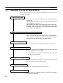
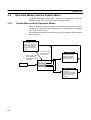
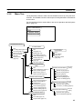
Operation Flow by the System Menu . . . . . . . . . . . . . . . . . . . . . . . . . . . . . . . . . . . . . . .
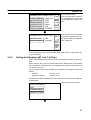
Starting the NT600S . . . . . . . . . . . . . . . . . . . . . . . . . . . . . . . . . . . . . . . . . . . . . . . . . . . .
Operation Modes and the System Menu . . . . . . . . . . . . . . . . . . . . . . . . . . . . . . . . . . . . .
Initializing Memory . . . . . . . . . . . . . . . . . . . . . . . . . . . . . . . . . . . . . . . . . . . . . . . . . . . . .
Registering the Screen Data . . . . . . . . . . . . . . . . . . . . . . . . . . . . . . . . . . . . . . . . . . . . . .
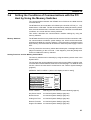
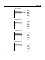
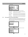
Setting the Conditions of Communications with the PC/Host by
Using the Memory Switches . . . . . . . . . . . . . . . . . . . . . . . . . . . . . . . . . . . . . . . . . . . . . .
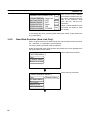
Starting the Operation . . . . . . . . . . . . . . . . . . . . . . . . . . . . . . . . . . . . . . . . . . . . . . . . . . .
Various System Settings . . . . . . . . . . . . . . . . . . . . . . . . . . . . . . . . . . . . . . . . . . . . . . . . . .
System Maintenance . . . . . . . . . . . . . . . . . . . . . . . . . . . . . . . . . . . . . . . . . . . . . . . . . . . .
xi
xii
xii
xii
1
2
4
10
13
16
19
20
23
24
27
30
31
43
47
56
63
65
66
67
68
72
79
83
92
93
101
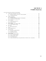
SECTION 4
NT600S Functions . . . . . . . . . . . . . . . . . . . . . . . . . . . . . . . . 113
4-1
4-2
4-3
4-4
4-5
4-6
4-7
4-8
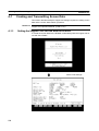
Creating and Transmitting Screen Data . . . . . . . . . . . . . . . . . . . . . . . . . . . . . . . . . . . . .
Outline of Functions . . . . . . . . . . . . . . . . . . . . . . . . . . . . . . . . . . . . . . . . . . . . . . . . . . . .
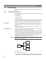
Screen Display . . . . . . . . . . . . . . . . . . . . . . . . . . . . . . . . . . . . . . . . . . . . . . . . . . . . . . . . .
Memory Tables . . . . . . . . . . . . . . . . . . . . . . . . . . . . . . . . . . . . . . . . . . . . . . . . . . . . . . . .
Bar Graphs . . . . . . . . . . . . . . . . . . . . . . . . . . . . . . . . . . . . . . . . . . . . . . . . . . . . . . . . . . . .
Lamps . . . . . . . . . . . . . . . . . . . . . . . . . . . . . . . . . . . . . . . . . . . . . . . . . . . . . . . . . . . . . . . .
Touch Switches . . . . . . . . . . . . . . . . . . . . . . . . . . . . . . . . . . . . . . . . . . . . . . . . . . . . . . . .
Numeral Setting . . . . . . . . . . . . . . . . . . . . . . . . . . . . . . . . . . . . . . . . . . . . . . . . . . . . . . . .
114
119
124
128
131
135
138
143
vii
SECTION 5
Using Host Link/NT Link/C200H Direct . . . . . . . . . . . . . . 153
5-1
5-2
5-3
5-4
5-5
Outline of Host Link / NT Link / C200H Direct Operation . . . . . . . . . . . . . . . . . . . . . . . . . . . .
Memory Tables and Bar Graph . . . . . . . . . . . . . . . . . . . . . . . . . . . . . . . . . . . . . . . . . . . . . . . . . .
Lamps, Touch Switches, and Numeral Setting . . . . . . . . . . . . . . . . . . . . . . . . . . . . . . . . . . . . . .
NT600S Status Control . . . . . . . . . . . . . . . . . . . . . . . . . . . . . . . . . . . . . . . . . . . . . . . . . . . . . . . .
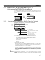
Notification of the Operating Status to the PC (Determining the NT600S Operating Status) .
154
164
180
192
197
SECTION 6
Using the RS-232C Interface Unit . . . . . . . . . . . . . . . . . . . 201
6-1
6-2
6-3
6-4
6-5
6-6
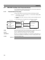
RS-232C Interface Unit Communications . . . . . . . . . . . . . . . . . . . . . . . . . . . . . . . . . . . . . . . . .
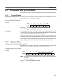
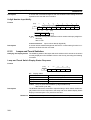
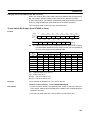
Commands Sent by the Host . . . . . . . . . . . . . . . . . . . . . . . . . . . . . . . . . . . . . . . . . . . . . . . . . . . .
Commands Sent by the NT600S . . . . . . . . . . . . . . . . . . . . . . . . . . . . . . . . . . . . . . . . . . . . . . . . .
Terminal Commands . . . . . . . . . . . . . . . . . . . . . . . . . . . . . . . . . . . . . . . . . . . . . . . . . . . . . . . . . .
Key to Programs . . . . . . . . . . . . . . . . . . . . . . . . . . . . . . . . . . . . . . . . . . . . . . . . . . . . . . . . . . . . .
EXAMPLE PROGRAM . . . . . . . . . . . . . . . . . . . . . . . . . . . . . . . . . . . . . . . . . . . . . . . . . . . . . . .
202
207
217
221
227
228
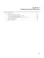
SECTION 7
Troubleshooting and Maintenance . . . . . . . . . . . . . . . . . . . 239
7-1
7-2
7-3
7-4
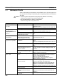
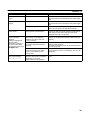
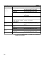
Hardware Faults . . . . . . . . . . . . . . . . . . . . . . . . . . . . . . . . . . . . . . . . . . . . . . . . . . . . . . . . . . . . .
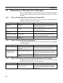
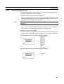
Responding to Displayed Error Messages . . . . . . . . . . . . . . . . . . . . . . . . . . . . . . . . . . . . . . . . .
Maintenance of the NT600S . . . . . . . . . . . . . . . . . . . . . . . . . . . . . . . . . . . . . . . . . . . . . . . . . . . .
Inspection and Cleaning . . . . . . . . . . . . . . . . . . . . . . . . . . . . . . . . . . . . . . . . . . . . . . . . . . . . . . .
240
242
245
250
APPENDICES . . . . . . . . . . . . . . . . . . . . . . . . . . . . . . . . . . . 253
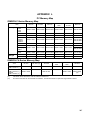
A. Specifications . . . . . . . . . . . . . . . . . . . . . . . . . . . . . . . . . . . . . . . . . . . . . . . . . . . . . . . . . . . .
253
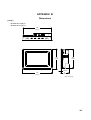
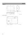
B. Dimensions . . . . . . . . . . . . . . . . . . . . . . . . . . . . . . . . . . . . . . . . . . . . . . . . . . . . . . . . . . . . . .
259
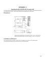
C. Handling the RS-232C/RS-422 Converter Unit . . . . . . . . . . . . . . . . . . . . . . . . . . . . . . . . .
261
D. NT600S Installation Environment . . . . . . . . . . . . . . . . . . . . . . . . . . . . . . . . . . . . . . . . . . . .
263
E. Method for Making the Cable for Connection to the PC/Host . . . . . . . . . . . . . . . . . . . . . .
265
F
Connecting to an RS-232C/RS-422 Converter Unit (1:1) . . . . . . . . . . . . . . . . . . . . . . . . . .
277
G. Function Restrictions Depending on the Support Tool . . . . . . . . . . . . . . . . . . . . . . . . . . . .
279
H. Making the Cable for Connection to the Support Tool . . . . . . . . . . . . . . . . . . . . . . . . . . . .
281
I.
NT600S Internal Processing . . . . . . . . . . . . . . . . . . . . . . . . . . . . . . . . . . . . . . . . . . . . . . . .
283
J.
Model List . . . . . . . . . . . . . . . . . . . . . . . . . . . . . . . . . . . . . . . . . . . . . . . . . . . . . . . . . . . . . .
287
K. Option List . . . . . . . . . . . . . . . . . . . . . . . . . . . . . . . . . . . . . . . . . . . . . . . . . . . . . . . . . . . . . .
293
L. PC Memory Map . . . . . . . . . . . . . . . . . . . . . . . . . . . . . . . . . . . . . . . . . . . . . . . . . . . . . . . . .
297
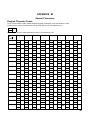
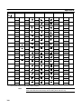
M. Special Characters . . . . . . . . . . . . . . . . . . . . . . . . . . . . . . . . . . . . . . . . . . . . . . . . . . . . . . . .
299
INDEX . . . . . . . . . . . . . . . . . . . . . . . . . . . . . . . . . . . . . . . . . 301
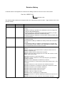
Revision History . . . . . . . . . . . . . . . . . . . . . . . . . . . . . . . . . 305
viii
About this Manual:
This manual describes the installation and operation of the NT600S Programmable Terminals (PTs) and
includes the sections described below. Further information is provided in manuals on the Host Interface
Units and Support Tool. Refer to the list in Section 1 Introduction.
Please read this manual completely and be sure you understand the information provide before attempting to install and operate a Programmable Terminal.
Section 1 introduces the PTs, describes the terminology used in this manual, and provides examples of
system configurations for programming and operation.
Section 2 provides procedures and specifications required to set up a PT system, including hardware
switch settings and installation.
Section 3 provides steps required for initial PT operation.
Section 4 describes functions used to create screens and control display attributes on the PT.
Included is automatic transfer of data from the host computer via character string and numeral tables.
Section 5 describes functions used to input data on-screen and transfer it to the host computer via the
numeral table.
Section 6 describes basic data transfer and maintenance functions.
Section 7 describes transferring screens online to and from the host computer.
Section 8 provides troubleshooting and basic maintenance methods, including battery replacement.
Appendices of OMRON products used with PTs, PT specifications, and a memory check table are provided at the back of the manual.
ix
Related Manuals and Their Contents:
The related manuals are indicated below.
The j symbol at the end of the manual number is the revision history symbol.
[Operating the programmable terminal and communicating with the host]
S NT600S Programmable Terminal Operation Manual (V022-E1-j)
. . . . . . . . . . . . . . . . . . . . . . . . . . . . . . . . . . . . . . . . . . . . . . . . . . . . . . . This manual
This operation manual is the manual for the NT600S itself.
The NT600S is a unit which integrates a programmable terminal body and host
interface unit. However, note that a C200H interface unit is required for communications using the C200H direct communication function. This operation manual
describes the functions and handling of both the programmable terminal body
and the host interface function.
[Creating and transferring screen data]
S NT Series Support Tool Ver.2j Operation Manual (V028-E1-j)
The screens displayed on the NT600S are created with the support tool and
transferred to the NT600S. This manual describes how to create and transfer
screen data.
x
PRECAUTIONS
This section provides general precautions for using the Programmable Terminal.
The information contained in this section is important for the safe and reliable application of the Programmable
Terminal. You must read this section and understand the information contained before attempting to set up or operate a Programmable Terminal.
1
2
3
Intended Audience . . . . . . . . . . . . . . . . . . . . . . . . . . . . . . . . . . . . . . . . . . . . . . . . . . . . . .
General Precautions . . . . . . . . . . . . . . . . . . . . . . . . . . . . . . . . . . . . . . . . . . . . . . . . . . . . .
Safety Precautions . . . . . . . . . . . . . . . . . . . . . . . . . . . . . . . . . . . . . . . . . . . . . . . . . . . . . .
xii
xii
xii
xi
3
Safety Precautions
1
Intended Audience
This manual is intended for the following personnel, who must also have knowledge of electrical systems (an electrical engineer or the equivalent).
S Personnel in charge of installing FA systems.
S Personnel in charge of designing FA systems.
S Personnel in charge of managing FA systems and facilities.
2
General Precautions
The user must operate the product according to the performance specifications
described in the operation manuals.
Before using the product under conditions which are not described in the manual
or applying the product to nuclear control systems, railroad systems, aviation
systems, vehicles, combustion systems, medical equipment, amusement machines, safety equipment, and other systems, machines, and equipment that
may have a serious influence on lives and property if used improperly, consult
your OMRON representative.
Make sure that the ratings and performance characteristics of the product are
sufficient for the systems, machines, and equipment, and be sure to provide the
systems, machines, and equipment with double safety mechanisms.
This manual provides information for using the Programmable Terminal. Be sure
to read this manual before attempting to use the software and keep this manual
close at hand for reference during operation.
WARNING It is extremely important that Programmable Terminals and related devices be
used for the specified purpose and under the specified conditions, especially in
applications that can directly or indirectly affect human life. You must consult with
your OMRON representative before applying Programmable Terminals to the
abovementioned applications.
WARNING Do not use input functions such as PT touch switches for applications where danger to human life or serious damage is possible, or for emergency switch applications.
3
Safety Precautions
Read these safety precautions carefully and make sure you understand them before using the Programmable Terminal so that you can use it safely and correctly.
Safety Conventions and their Meanings
This operation manual uses the following conventions and symbols to indicate
cautions, warnings, and dangers in order to ensure safe use of the PT. The cautions, warnings, and dangers shown here contain important information related
to safety. The instructions in these cautions, warnings, and dangers must be observed. The conventions used and their meanings are presented below.
DANGER!
Indicates information that, if not heeded, is likely to result in loss of life or serious
injury.
WARNING Indicates information that, if not heeded, could possibly result in loss of life or serious injury.
CAUTION
xii
Indicates information that, if not heeded, could result in relatively serious or minor
injury, damage to the product, or faulty operation.
Safety Precautions
3
WARNING:
S Do not attempt to take the NT600S apart and do not touch any internal parts
while the power is being supplied. Doing either of these may result in electrical
shock.
S Switch off the power before replacing the backlight. Otherwise you could sustain an electric shock.
Caution:
S Select a proper location referring to Appendix D Installation Environment (page
263).
Always switch OFF the power before assembling equipment or connecting
cables. Otherwise you could sustain an electric shock or equipment could be
damaged.
S Fit crimp-style terminals to the power cable. Connecting the wires of the cable
to the terminal block directly after merely twisting them together could cause
fire and other hazards.
S The combined lengths of each of the I/O connecting cables must not exceed a
total of 12 m (or 6 m for CjjH models).
S Do not use input functions such as PT touch switches for applications where
danger to human life or serious damage is possible, or for emergency switch
applications.
S On unpacking the NT600S, check its external appearance and confirm that
there is no damage. Also confirm that there is no abnormal noise on shaking the
unit lightly. The product may malfunction if it is damaged.
S If the DIP switch settings have been changed when the NT600S is powered,
reset the power to the NT600S. The changes with the DIP switches become
effective only after the power supply is reset.
S In order to ensure system safety, be sure to periodically read the PT operating
status bit at the host during operation to confirm that the PT is always operating
correctly.
S During work at the panel, take care to ensure that no metal scraps enter the
unit. Otherwise, the product may malfunction.
S For the connection to the power supply terminal block, twisted wires of 2 mm2
or greater cross sectional area and M 3.5 size crimp terminals must be used.
Use crimp terminals to connect the power supply to the power input terminals.
Recommended crimp terminals for M3.5 are given below.
Tighten the screws on the terminal block to a torque of 0.8 N·m.
Otherwise fire may occur.
S After connecting a communication cable, always secure it with the screws.
Otherwise the cable may disconnect, causing operation to fail.
S The cable’s tensile load is 30 N. Do not subject it to loads greater than this.
Otherwise a discontinuity may occur, causing operation to fail.
xiii
3
Safety Precautions
S Do not install the NT600S at sites subject to the following conditions:
Otherwise, the product may malfunction.
Severe temperature variations
Temperatures or humidities outside the ranges stated in the specifications
High humidity, condensation
Splashing chemical agents
Severe oil splashing
Corrosive or flammable gases
Strong vibrations or shocks
Direct exposure to wind and rain (outdoor sites)
Strong ultra-violet irradiation
S Take adequate measures to ensure shielding if the NT600S is used at a location subject to any of the following conditions.
Otherwise, the product may malfunction.
Static electricity, or noise from other equipment
Strong electromagnetic fields
Nearby power cables
Potential exposure to radioactivity.
S Carry out grounding correctly in order to prevent misoperation due to noise.
S Confirm system safety before turning the power ON/OFF or resetting.
Otherwise the system may operate unpredictably.
S Carefully check the operation of all screen data and host programs before using them. If incorrect, the system may operate unpredictably.
Otherwise the system may operate unpredictably.
S Turn off the NT600S power supply when connecting or disconnecting connectors.
S Check that the current capacity of the equipment to be supplied is within 150
mA before using the +5V output of pin No.6. Otherwise, the product may malfunction.
The current capacity of +5 V output of NT600S is:
+5 V 5%, 150 mA max. with ST211(B)-Vj, and
+5 V 5%, 100 mA max. with ST121(B)-Vj.
S Press touch switches with a force of no greater than 20 N.
Applying higher force may cause glass to break, cause injuries, and prevent
operation.
S Do not press touch switches carelessly while the backlight is off or while nothing is displayed on the screen.
Otherwise the system may operate unpredictably.
Only press touch switches after confirming system safety.
S In a system where the user program operates according to the PC cycle time,
the system operation may not be constant because of cycle time fluctuations.
Consider this point when designing the system.
S Do not disassemble for repairs or modification.
Otherwise the product may malfunction.
xiv
Safety Precautions
3
S The disposal of the NT600S (and used backlights) may be regulated by national or local authorities. Dispose of them in accordance with the laws and regulations of the relevant country and local authority.
S Never short the + and – terminals of the battery. Do not recharge, take apart,
deform, or discharge it into open flame.
Attempting any of these will lead to hazards such as fire, leakage of electrolyte,
rupture, etc.
S Depending on how the power is switched ON/OFF, the entire system may stop.
Follow the correct procedure when switching the power ON/OFF.
Otherwise the system may operate unpredictably.
S Always turn off the power at both the PC and PT before connecting the C200H
interface cable.
Otherwise the system may operate unpredictably.
Switch off the power to the NT600S and PC before disconnecting/connecting
the cable.
S Set so that there is no overlap between the PT status control area and PT status notify area. Otherwise the system may operate unpredictably.
S When transferring the data in units of screens, if there are changes in memory
table and/or direct connection, transfer such data along with the screen data.
Otherwise the system may operate unpredictably.
xv
SECTION 1
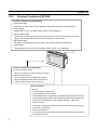
Functions of the NT600S
NT600S is a new programmable terminal (PT) which incorporates a host interface unit and a RS-232C interface unit in a
programmable terminal body. It can be easily installed and used.
This section gives the operation examples and characteristics of the NT600S so that you will understand the applications of
the NT600S.
1-1
1-2
1-3
1-4
1-5
1-6
1-7
Role and Operation of NT600S . . . . . . . . . . . . . . . . . . . . . . . . . . . . . . . . . . . . . . . . . . . . . . . . .
1-1-1 Operations of NT600S . . . . . . . . . . . . . . . . . . . . . . . . . . . . . . . . . . . . . . . . . . . . . . . . . . .
Functions of NT600S . . . . . . . . . . . . . . . . . . . . . . . . . . . . . . . . . . . . . . . . . . . . . . . . . . . . . . . . .
1-2-1 Features . . . . . . . . . . . . . . . . . . . . . . . . . . . . . . . . . . . . . . . . . . . . . . . . . . . . . . . . . . . . . .
1-2-2 Principal Functions of NT600S . . . . . . . . . . . . . . . . . . . . . . . . . . . . . . . . . . . . . . . . . . . .
1-2-3 Comparison between NT600S and NT600M . . . . . . . . . . . . . . . . . . . . . . . . . . . . . . . . .
1-2-4 Differences Between Existing Models and NT600S-ST121/ST211-EV3 . . . . . . . . . . . .
1-2-5 Displays . . . . . . . . . . . . . . . . . . . . . . . . . . . . . . . . . . . . . . . . . . . . . . . . . . . . . . . . . . . . . .
System Configuration . . . . . . . . . . . . . . . . . . . . . . . . . . . . . . . . . . . . . . . . . . . . . . . . . . . . . . . . .
Direct Connection Function . . . . . . . . . . . . . . . . . . . . . . . . . . . . . . . . . . . . . . . . . . . . . . . . . . . .
1-4-1 What is the NT Link (1:N) . . . . . . . . . . . . . . . . . . . . . . . . . . . . . . . . . . . . . . . . . . . . . . . .
1-4-2 C200H Direct Communication . . . . . . . . . . . . . . . . . . . . . . . . . . . . . . . . . . . . . . . . . . . .
Functions of the Allocated Bits and Words . . . . . . . . . . . . . . . . . . . . . . . . . . . . . . . . . . . . . . . .
Communications by RS-232C . . . . . . . . . . . . . . . . . . . . . . . . . . . . . . . . . . . . . . . . . . . . . . . . . . .
Before Operating . . . . . . . . . . . . . . . . . . . . . . . . . . . . . . . . . . . . . . . . . . . . . . . . . . . . . . . . . . . . .
2
3
4
4
6
7
8
9
10
13
14
15
16
19
20
1
Role and Operation of NT600S
1-1
Section 1-1
Role and Operation of NT600S
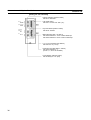
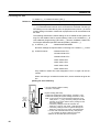
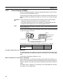
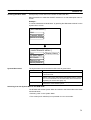
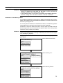
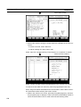
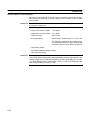
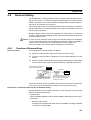
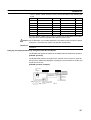
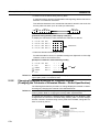
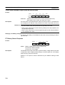
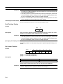
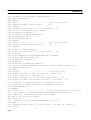
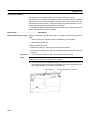
NT600S is a programmable terminal used to display and transmit the information
in an FA site. The following gives a general description of the role and operation of
the NT600S for those who use a programmable terminal (PT) for the first time.
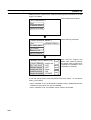
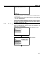
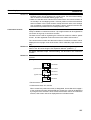
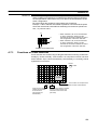
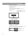
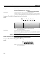
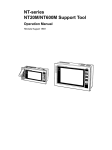
Production Line Status
Monitoring
The NT600S displays real-time information about the system and equipment
operating status, etc.
Production Control
Product
1994/1/25
NT20M
Today’s target
560 units
441 units
Current Production
305 units
275 units
54.5 %
63.0 %
% achieved
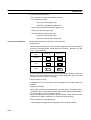
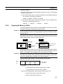
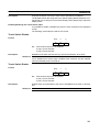
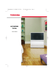
Messages
NT600M
The NT600S warns of system or equipment failures and prompts the appropriate
remedial action.
Alarm
Assembly line B
–
Positioning pin
is defective.
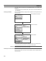
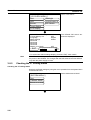
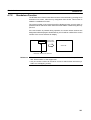
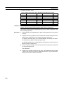
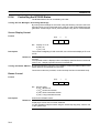
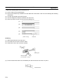
Panel Switch Functions
Setting touch switches on the NT600S allows workers to use the NT600S as an
operating panel. Production data input to the NT600S can be transmitted to a PC.
Electroplating Control
Transport
Clamp
2
UnClamp
Role and Operation of NT600S
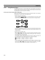
1-1-1
Section 1-1
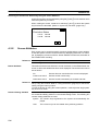
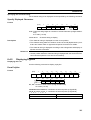
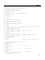
Operations of NT600S
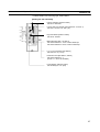
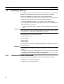
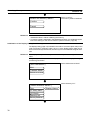
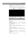
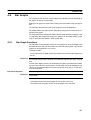
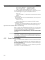
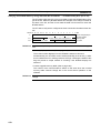
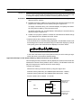
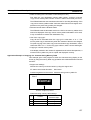
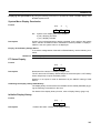
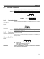
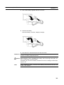
Displays Screens
The information to be displayed (screen data) can be created on a computer by
using support tools and stored in the NT600S. The screen data can be displayed
on the NT600S in response to the instructions from a PC/Host or touch switch operation.
Host
PC
The screen data designated by
instructions from PC/Host or
touch switch operation is
displayed.
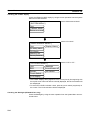
Receives Data from a PC/
Host
The NT600S can be connected to a PC/Host, and receive necessary data from it,
by using the host link function, the NT link function, the C200H direct communication function, or RS-232C.
Host link, NT link, C200H direct
communication, RS-232C
Host
PC
OMRON’s PC
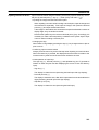
Sends Data to a PC
Data input through a touch panel can be sent to a PC.
PC
Touch panel
ON/OFF information,
numeric data, etc.
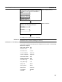
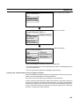
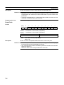
Screen Data
The screen data to be displayed on the NT600S can be created by a computer by
using support tools. Connect the NT600S to a PC/AT with an RS-232C cable so
that the screen data are transferred to the NT600S.
Create screen data.
RS-232C
PC/AT
(support tools)
Screen data
This connection is made only to
transmit the screen data by using
NT600S and tools.
(If C200H direct communication is
used, the support tool and Host
can both be connected at the
same time.)
3
Functions of NT600S
1-2
Section 1-2
Functions of NT600S
The NT600S has the following features which are different from those of existing
NT600M.
1-2-1
Features
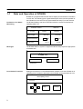
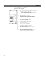
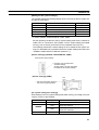
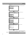
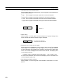
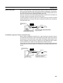
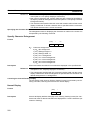
Downsized Body
S The NT600S has thin depth (64 mm or less in the panel) in the NT series.
S The width is shorter by 50 mm, maintaining the existing display area.
S The tool connectors are located at the rear of the unit.
S The communication cable connectors are housed in the unit so that they do not
protrude from the unit.
S The tool connectors and the PC/Host communication connectors are used in
common.
Construction Best Suited to the FA Environment
S Easy-to-read screen even in direct sunlight.
S Two types of panel are available: the STN LCD panel with backlight and the amber EL display panel.
S Its backlight unit and battery can be replaced at the operation site.
S Waterproofed to a standard equivalent to IP65 and NEMA 4.
640 dots
POWER
RUN
400 dots
Wide angle of visibility,
50_ to left and 40_ to right
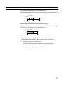
1:1 and 1:N Communications Possible with “NT Link” Method
S Connection in 1:1 and 1:N NT link systems is possible.
S All you have to do is connect to the host; no complicated installation work is necessary.
S A flash memory is used for the screen data memory, making battery backup unnecessary.
S The following communication methods are standard: host link (direct), NT link
(1:1, 1:N), and RS-232C.
4
Functions of NT600S
Section 1-2
Availability of the C200H Direct Communication Function
The C200H direct communication function can be used if the C200H interface unit
(NT-LB122), which must be purchased separately, is mounted to the NT600S.
Touch Switch Operation
The System Menu can be displayed by using the touch switches located in four
corners of the screen.
Compatibility with NT600M
Existing screen data, user programs, and support tools are compatible.
5
Functions of NT600S
1-2-2
Section 1-2
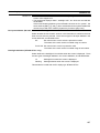
Principal Functions of NT600S
Functions Related to the Data Display
S Character display
Characters of various sizes can be displayed. Characters can flash or be highlighted.
S Figure display
Straight lines, circles, and other graphic figures can be displayed.
S Memory data display
Contents of the character-string memory table and the numeral memory table can be displayed. The memory table contents can be changed from the PC/Host.
S Bar graph display
Bar graphs corresponding to the contents of the numeral table can be displayed.
S Lamp display
Lamps which turn on or flash as controlled by the PC/Host can be displayed.
Functions Related to the Data Input
S Input by the touch switch
Data can be input by simply touching the screen.
S Numeric setting function
The touch keys can be assigned with numeric
values so that the numeric values can be input
at the operation site and sent to the PC.
Other Functions
S Buzzer
A built-in buzzer can be used.
S Communications with a PC/Host
The NT600S can be connected to a PC/Host to enable data to be received
and touch switch information to be sent by using the host link function, NT
link function, C200H direct communication function, or RS-232C.
S System function
The system setting and maintenance can be executed by using the System Menu on the screen.
S Screen data creation
The screen data can be created by using support tools on the computer
and stored in the unit.
6
Functions of NT600S
1-2-3
Section 1-2
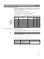
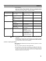
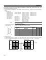
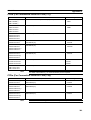
Comparison between NT600S and NT600M
The NT600S is a unitary PT which incorporates a system ROM, screen memory,
and a host I/F unit (host link, NT link, and RS-232C) as the standard equipment in
one body.
The NT600S has the following features which are different from those of existing
NT600M.
Function
NT600S-ST121/-ST211-EVj
NT600M-DT122
Communication
Host link/NT link/NT Link (1:1, 1:N)/RS-232C
Host I/F units are required.
incorporated.
The C200H direct communication function can
be used if the separately purchased C200H
interface unit (NT-LB122) is mounted on the
rear of the NT600S.
Communication connector
The communication connector (9-pin) for a
PC/Host is shared with that for a support tool.
When using the C200H direct communication
function, there are separate connectors for
communications with the support tool and PC/
Host.
Both the support tool connector (9-pin) and
PC connector (25-pin) are located on the
back side.
Host RUN input terminal/
Alarm output terminal
Not provided
Provided
System keys
Not provided
Provided
Contrast control
Back side (ST121)
Expanded I/O unit
Expanded not possible
Possible with DN type
Waterproof performance
NEMA4
Conforms to IP52F.
Visibility in direct sunlight
Good (ST121)
None (ST211)
Barely visible
Power supply
24 VDC, more than
15 W (ST121(B))
24 VDC, more than
25 W (ST211(B))
100/200 VAC
Allowable momentary
power interruption time
Not guaranteed
5 msec
System ROM
Built in (512 KB, not replaceable)
System ROM compatible with host I/F unit is
required.
Resume function
Provided (if optional battery is mounted)
Provided
History retaining function
Provided (if optional battery is mounted)
Provided
Screen transfer
YES
YES
Screen data compatibility
YES (Note 1)
–
PC ladder compatibility
YES
–
Backlight replacement
YES (ST121 (B))
NO
Screen data memory
Built in (flash memory only)
Optional (select from EP-ROM, SRAM, and
EEP-ROM)
Screen data memory
capacity
128 KB
256 KB max.
Outside dimensions
275 192 71mm
325 198 105mm
Note
None (ST211)
Front side
1. If a system key function is required on continuous screens or for numerical
setting or buzzer stop, use a support tool and set the touch switches which
have the system key function in such screens.
For details, refer to “System Key Functions” on page 142.
128 KB of screen data memory capacity is equivalent to 200 screens consisting mainly of messages, or 70 screens consisting mainly of figures.
7
Functions of NT600S
1-2-4
Section 1-2
Differences Between Existing Models and
NT600S-ST121/ST211-EV3
Difference between direct connection Ver.4 and Ver.5
Ver.5 of the direct connection function has the following additional functions in
comparison with Ver.4.
S “Thumbwheel” type setting possible with the numeral setting function.
S Upper and lower limit check can be set with the numeral setting function.
S The type of operation (alternate, set, reset) can be selected for touch switch input notification.
S Indirect specification possible for numeral display and character string display
functions.
8
Functions of NT600S
1-2-5
Section 1-2
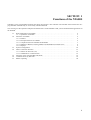
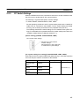
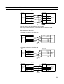
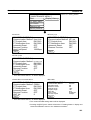
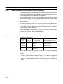
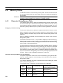
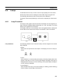
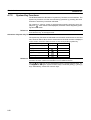
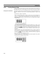
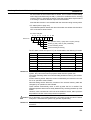
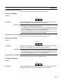
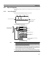
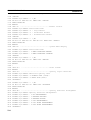
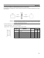
Displays
The NT600S can display various kinds of elements such as characters, numeric
value, lamps, touch switches, and bar graphs on a screen. The screen data displayed on the NT600S are created by using support tools on a computer.
Touch switches
Characters
(character string)
Characters (text)
Stop
Line A
Machine name
Production qty.
:
:
Restart
NT600S-ST121
137 units
Numeric value
(Numeral table)
30%
Bar graph
0%
Stage 1
Characters (text)
50%
Stage 2
100%
Stage 3
Lamps
Characters and marks which do not need to be changed can be written directly to
the screen.
Characters (character-string memory table)
Character-strings stored in the character-string memory table are displayed. The
display characters can be changed by changing the data stored in the characterstring memory table.
Numeric Values (numeral memory tables)
Numbers stored in the numeral memory table are displayed. The display numbers
can be changed by changing the data stored in the numeral table. Hexadecimal
values can also be displayed.
Lamps
Lamps indicate the operating status. They are controlled by the PC/Host and can
be lit (reversed) or made flash (alternates normal with reversed displays).
Touch Switches
Touch switches can be set anywhere on the screen. Touching the screen at a touch
switch location can switch the display (stand-alone function or display switch function) or notify the PC/Host (notification function). The touch switches can be lit or
made flash by controlling from the PC/Host in the same way as the lamps.
Numeric Keys/Thumb wheel These are the touch switches used to input numeric values.
Bar Graphs
The bar graph extends and contracts in proportion to the data stored in the numeral memory table. A percentage value can also be displayed simultaneously.
Marks
Marks can be designed, created, and handled like characters by the user.
9
System Configuration
1-3
Section 1-3
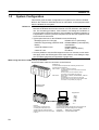
System Configuration
This section gives the basic configuration of a system which uses an NT600S.
Refer to the manual for individual device for information on the equipment other
than the NT600S in the system.
Reference S The following four communication methods are supported for communications
between the NT600S and PC/Host: host link, NT link, RS-232C, and C200H direct. For the setting procedure, refer to Section 3-6 Setting the Conditions of
Communications with the PC/Host by Using the Memory Switches (page 83). It
is impossible to connect a personal computer used to drive the support tool and
a PC/Host at the same time.
S Typical option devices for the NT600S include the following.
Backlight (spare for LCD type)
NT600S-CFL01 (white lamp)
Reflection-suppressing protective sheet NT600M-KBA04 (5 sheets/pack)
Battery
C500-BAT08
Chemical-resistant cover
NT600S-KBA01
(made of silicone rubber)
C200H I/F Unit
NT-LB122
S It is also possible to use the NTM support tool Ver.4.2. However, some restrictions apply when the NTM support tool is used. Refer to 3-8-5 Setting the Support Tool Mode (page 99) and Appendix G (page 279).
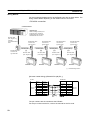
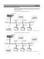
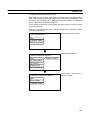
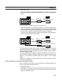
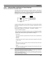
When using the Host Link/NT Link (1:1) Function
Use an RS-232C cable for connection to the PC/Host
OMRON’s PC
Controls NT600S as required while controlling machines and
monitoring the production line.
With host link: C series, CVM1/CV series PC
The NT600S can be connected to CPU units and
host link units.
However, there are some models to which
connection is not possible (see page 31).
With NT link:
CPM1, CQM1, C200HS, C200HX/HG/HE, CVM1/CV
series PCs
The NT600S can be connected to a CPU unit.
However, there are some CPU unit models to which
connection is not possible (see page 43).
RS-232C cable
(for host link)
Support tool
NT600S
Gives displays of production line
monitoring and instructions to the
operation site and notifies the switch
ON/OFF status and numeric value inputs
to the PC.
10
Computer (support tool)
Connected to NT600S as required and used to transfer the
NT600S screens and make settings for the NT600S.
Computer
Support tool
: IBM PC/AT or compatible
: Type NT-ZA3AT-EV2
System Configuration
Section 1-3
Reference Host link and NT link (1:1) communications can be performed with RS-422A by
using an RS-232C/RS-422A converter unit (type NT-AL001), but communications with RS-485 are not possible. For details on the wiring for RS-422A, refer to
“Appendix F Connecting to an RS-232C/RS-422A Converter Unit” (page 277 of
the appendix).
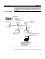
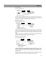
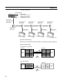
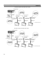
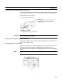
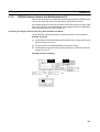
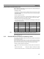
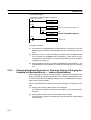
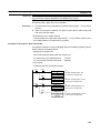
NT Link (1:N) Systems
When NT600S is connected to a PC in a 1:N connection, use an RS-232C cable
and RS-422A/485 cables.
C200HX/HG/HE
OMRON PC
Controls the NT600S as required
during machine control, line
monitoring, etc.
C200HX/HG/HE can be used.
RS-232C cable
(max. length: 2 m)
RS-232C/RS-422
converter unit,
type NT-AL001
RS-422A/485 cable (*1)
RS-232C/RS-422
converter unit,
type NT-AL001
RS-232C/RS-422
converter unit,
type NT-AL001
(*1) : Total cable length: 500
(*2) : For connection to an
NT600S-ST121(B)-Vj,
a separate power
supply is required.
RS-422A/485 cable (*1)
+5V (*2)
(150 mA)
+5V (*2)
(150 mA)
RS-232C cable
(max. length: 2 m)
RS-232C cable
(max. length: 2 m)
NT600S
NT600S
In an NT link (1:N), up to
eight NT600S units can be
connected to one PC port.
In addition to applications such as monitoring
production lines and displaying messages such
as instructions transmitted to the workplace,
also notifies the ON/OFF status of switches and
numerical input to the PC.
Support tool
Personal computer (support tool)
Connected to the NT600S when necessary to
transmit created screens to the NT600S
screens and set NT600S settings.
Personal computer: IBM PC/AT or compatible
Support tool: NT-ZA3AT-EV2
Reference When connecting the C200HX/HG/HE and an RS-232C/RS-422 converter unit,
use a converter unit whose lot number is 15Y5 or later. Converter units of lot numbers previous to 15Y5 cannot be connected.
11
System Configuration
Section 1-3
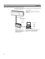
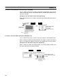
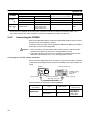
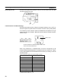
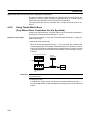
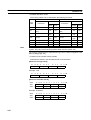
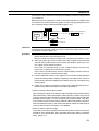
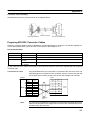
When using the C200H Direct Communication Function
Use an I/O connecting cable for the connection to the PC, and an RS-232C cable
for connection to the Host.
PC made by OMRON
Controls the NT600S as required for machine control, line
monitoring, etc.
C200H direct communication: With CjjH, C200H, C200HS,
C200HX/HG/HE
I/O connecting cable
C200H interface unit
Type NT-LB122
Support tool
NT600S
In addition to applications such as
monitoring production lines and displaying
messages such as instructions
transmitted to the workplace, also notifies
the ON/OFF status of switches and
numeral input to the PC.
12
Personal computer (support tool)
Connected to the NT600S when necessary to transmit created
screens to the NT600S, and to set NT600S settings.
Personal computer : IBM PC/AT or compatible
Support tool
: Type NT-ZA3AT-EV2
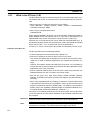
Direct Connection Function
1-4
Section 1-4
Direct Connection Function
The communication method applied between the NT600S and the PC is either a
host link or NT link or C200H or RS232C direct.
The following deals with the “direct access” available when a host link, NT link, or
C200H direct is used, and the communication with a PC.
Reference For the communication through RS-232C, refer to “1-6 Communications by
RS-232C” (page 19)
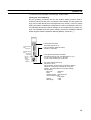
The NT600S can be used to refer to the contents necessary for the display information or to allocate the bits and words used for storing the input data to any
area in the PC. The NT600S can directly write and read such allocated bits and
words so as to change the display elements, control the operating status, and
notify the status.
This function is called the “direct connection function”. The NT600S is designed
exclusively for use with the direct connection.
The bits and words allocated by the direct connection function are called “allocated
bit” and “allocated word” respectively.
This function allows to read the information to be displayed on the NT600S from
the memory area in the PC and to write it to the memory table in the NT600S. Also,
the data input on the NT600S can be written to the PC’s memory area. The
NT600S screen status can be switched according to the PC’s memory area, and
the NT600S’s status data can be written to the PC’s memory area.
NT600S
PC
DM area
Auxiliary relay area
Internal relay area
Timer/counter
Features of the Direct Connection Function
S The bits and words referring to operating status and work instruction information
and those for storing input data can be freely allocated to almost any part of the
PC memory. Bits and words in the PC can be referenced from any memory table.
S The NT600S can directly refer to PC bit and word data so that it can be connected to a PC without changing the PC program which controls currently running production line.
S The area to control and notify the NT600S status, including display screens, ON/
OFF of the backlight/EL display screen, and buzzers can be freely allocated to
any part of the PC memory.
The direct connection function allows the NT600S to directly read and write almost
all bits and words in the PC and to automatically change the NT600S screen display. This function can reduce the load on the PC so that the program development
efficiency of the PC improves.
13
Direct Connection Function
1-4-1
Section 1-4
What is the NT Link (1:N)
The NT link uses the direct connection function and can execute high-speed communications with the PC. The PCs that can be connected with NT Link are as follows.
S When using the host link built into the CPU unit, SRM1
CPM1 (RS-232C Adapter required), CQM1, C200HS, C200HX/HG/HE,
CVM1/CV Series PCs, SRM1
S When using a communication board
C200HX/HG/HE
When using the NT600S in an NT link, two communications modes are possible: a
single NT600S can be connected to one PC (1:1 NT link), or alternatively, up to
eight NT600S units can be connected to a single PC port (1:N NT link).
However, the 1:N connection NT link can be used with C200HX/HG/HE only. In
the following sections, the NT link communication mode in general will be indicated
by the term “NT link”, a 1:1 connection NT link will be indicated by
“NT link (1:1)”, and a 1:N connection NT link will be indicated by “NT link (1:N)”.
Features of the NT Link
The NT link method has the following features.
S It allows high-speed communications with a specific PC.
S Data can be written to the memory area of the PC in bit units.
This means that different bits of the same word to which a touch switch is allocated can be used for different applications (for example the allocation of a
lamp).
However, since data is written to the DM area in word units, it is not possible to
use the other bits of words to which touch switches have been allocated for other
applications in the case of this area.
S Can be used even while the PC is in the run mode. When using a host link, the
NT600S switches from the run mode to the monitor mode.
S With NT link (1:N), up to eight PT30, NT30C, NT20S, NT600S, NT620S,
NT620C, or NT625C units can be connected to a single PC port and used simultaneously.
S When using C200HX/HG/HE, by installing an expansion communication board
in the option slot of the CPU unit, it is possible to connect up to three NT link (1:N)
systems (comprising a total of 24 NT600S units). For details on communication
boards, refer to the “SYSMAC C200HW-COM01 to C200HW-COM06-E Communication Board OPERATION MANUAL” (W304-E1-j).
Since there is compatibility between the NT link and host link, the host link direct
connection data can be used without alteration for the NT600S screen data and
PC programs.
Reference When communication is conducted in a 1:N NT link, RS-232C/RS-422 converter
units (NT-AL001) must be used for the connections to the individual PTs.
Note
14
When an NT600S-ST121(B)-EVj is connected, a +5 V (150 mA) power supply is
required for the converter. Do not draw the power supply from the PT.
Direct Connection Function
1-4-2
Section 1-4
C200H Direct Communication
C200H direct communication allows communication with CjjH, C200H, and
C200HS CPU units by using the “direct connection” function.
Advantage of C200H Direct Communication
S Since an I/O connecting cable is used for connection to each CPU unit, highspeed communication is possible.
S Data can be written to the PC memory area in bit units, This means that the unused bits of words allocated to touch switches can be used for other applications
(for example, lamp allocations.)
The C200H direct communication function is compatible with the host link and NT
link functions. This means that NT600S screen data and PC programs handled
with the host link and NT link functions can also be used with the C200H direct
communication function as they are.
Caution In a system where the user program operates according to the PC cycle time, the
system operation may not be constant because of cycle time fluctuations.
Consider this point when designing the system.
15
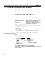
Functions of the Allocated Bits and Words
1-5
Section 1-5
Functions of the Allocated Bits and Words
Elements displayed on the NT600S and the NT600S status can be allocated to the
bits and words of the PC. By changing the contents of the bits and words, the
NT600S can be controlled by the PC. It is also possible to send data to the PC by
pressing the touch switches on the NT600S.
S Controlling the NT600S by a PC
The following NT600S functions can be controlled by a PC.
Screens
: Display of designated screens, confirmation of
screen numbers, etc.
Memory tables
: Writing to a memory table, copying from a
memory table to another memory table, etc.
Lamps and touch switches
: Display instructions, confirmation of display
status, setting of input prohibition, etc.
System control
: Buzzer ON/OFF, ON/OFF of backlight or EL
display, and other NT600S status
S Notifying from the NT600S to a PC
Data in the NT600S is sent to a PC when a touch switch is pressed. The following
types of data are sent to a PC.
- NT600S status
- Touch switch status
- Numeric values input by the numeral keys by using the touch switches
- Changes in a memory table after copying between memory tables
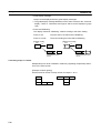
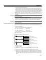
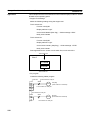
Functions of Display Elements
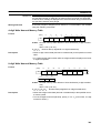
S Lamps
Allocation destination: Bit
NT600S
PC
Lamp #1 (Bit 000100)
Lit
Switch 1: ON (Bit 000100)
Unlit
Switch 2: OFF (Bit 000101)
Lamp #2 (Bit 000101)
PC’s bit status is displayed by the “Lamp” on the NT600S.
The lamp comes on (flashes) when the PC’s bit status is ON (1), and goes off
when it is OFF (0).
16
Functions of the Allocated Bits and Words
Section 1-5
S Touch switches
Allocation destination: Bit
Touch switch #12
Bit 009012
NT600S
PC
Bit 009012: ON
The lamp comes on (flashes) when the PC’s control bit is ON (1) and goes off
when it is OFF (0). While the touch switch is pressed, the PC’s notification bit
turns ON (1), and when it is released, the bit turns OFF (0).
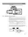
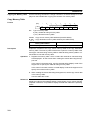
S Numeral memory table
Allocation destination: Word
Numeral memory
table 1 (TIM003)
NT600S
PC
Numeral memory table 150 (0005CH)
Allocate numeral memory tables to arbitrary words in the PC. If word contents
change when corresponding numeral memory table is displayed on the screen,
the value on the screen will also change. Monitoring of words can also be made
easily.
Reading and writing are executed so that the contents of allocated words are
always the same as those of the numeral memory tables.
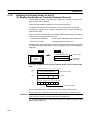
S Character-string memory table
Allocation destination: Word
NT600S
PC
(“a”, “b”)
(“c”, “d”)
(“e”, “f”)
Character-string memory table 1
Allocated word number: 3ch
First word: DM0100
Allocate character-string memory tables to arbitrary words in the PC. If word
contents change when corresponding character-string memory table is displayed on the screen, the value on the screen will also change. Messages can be
displayed easily.
Reading and writing are executed so that the contents of allocated words are
always the same as those of the character-string memory tables.
17
Functions of the Allocated Bits and Words
Section 1-5
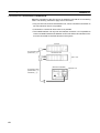
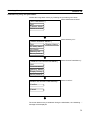
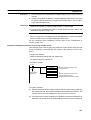
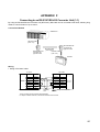
Functions of the PT Status Control Area (PC to NT600S)
The “PT status control area” is used to control the NT600S status. When data is
written to this area in the PC, the NT600S reads the contents and operates according to the contents.
[Example of the PT status control area application]
When data is written to the PT status control area, the NT600S will operate as given below.
Screen 3
display
NT600S
PC
PT status control area
Screen switch setting
Memory table
Copy setting
PT status control bits
Continuous
buzzer sound
Numeral memory table 50
Copy
Numeral memory table 7
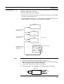
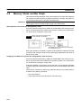
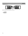
Functions of the PT Status Notify Area (NT600S to PC)
The “PT status notify area” is used to notify the changes of the NT600S status.
When a change is made in the NT600S status, the change is written to this area in
the PC. By reading the data from the area, the NT600S status can be checked.
[Example of the PT status notify area application]
When a change is made in the NT600S status, such change will be notified to the
PT status notify area as mentioned below.
NT600S
12345678
PC
Numeral memory table 13
PT status notify area
12345678
Currently display screen
Content update memory table
PT status
Allocated word (numeral table 13)
12345678
18
Start
Start + 1
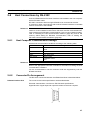
Communications by RS-232C
1-6
Section 1-6
Communications by RS-232C
Control of the NT600S by a Host is executed by two kinds of commands supported
by the RS-232C interface which is built into the NT600S.
Operation commands
Operation commands are used to control the display and status of the running
NT600S as well as to notify information.
Screen display, data writing, data inquiries, etc.
Notification of the NT600S operation contents to the Host.
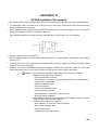
Terminal commands
Terminal commands are used to use the NT600S as a display terminal of the Host.
When the NT600S is used as a display terminal, it can display characters and figures in accordance with instructions given by the Host, independently of the
screens registered to the NT600S.
These commands are also used if unexpected problems occur.
19
Before Operating
1-7
Section 1-7
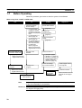
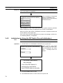
Before Operating
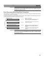
Follow the procedure given below to start the system of the NT600S.
When using Host Link/NT Link/RS-232C
Host
PC
Check and change
the PC settings.
S For the host link, refer
to page 31 and the
manuals for the host
link unit and peripheral
tools.
S For the NT link (1:1),
refer to page 43.
S For the NT link (1:N),
refer to page 47.
S No special setting required for C200H direct communication
S For RS-232C:
Refer to page 63
Refer to the manuals
supplied with the Host.
Connect to the
NT600S.
Check and change the
connection at the Host.
Support tool
Set the DIP switches.
(page 26)
Install to the
operation panel.
(page 27)
Connect the power
supply.
(page 28)
Connect to the PC.
S
S
S
S
(page 31)
Refer to the manuals
supplied with the Host.
(Host link: page 31)
(NT link (1:1): page 43)
(NT link (1:N): page 47)
(C200H direct communication: page 56)
S (RS-232C: page 63)
Create the PC
program.
Create the Host
program.
NT600S
Refer to Section 6.
Refer to the manuals
supplied with the Host.
Check the settings
and communications.
Install support tools to
the computer.
Create the screens.
Transfer the
screen data.
(page 79)
(refer to Section 4 and the
manuals for the support
tools)
Start operation.
Note
Before starting actual operation, check the screen data and the program to be run
at the Host completely for its operation.
Reference For usable support tools, refer to Appendix H Making the Cable for Connection to
the Support Tool (page 281)
20
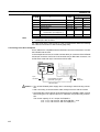
Before Operating
Section 1-7
Refer to the following manuals for the equipment and software.
Equipment or Software
Manual Title
Manual Number
Support tools
NT-series Support Tool Operation Manual
V028-E1-j
PCs
SYSMAC C20H/C28H/C40H/C60H Operation Manual
(Programming/RS-232C Interface)
W176-E1-j
SYSMAC C120/C500 User’s Manual (Programming)
W060-E1-j
SYSMAC C200H Operation Manual
W130-E1-j
SYSMAC C200HS Installation Guide
W236-E1-j
SYSMAC C200HS Operation Manual
W235-E1-j
SYSMAC C200HX/HG/HE Installation Guide
W302-E1-j
SYSMAC C200HX/HG/HE Operation Manual
W303-E1-j
SYSMAC C1000H/C2000H Operation Manual
W140-E1-j
SYSMAC CQM1 Operation Manual
W226-E1-j
SYSMAC CQM1-CPM1 Programming Manual
W228-E1-j
SYSMAC CV500/CV1000/CV2000 Operation Manual (Ladder)
* For a PC of the CVM1 series, refer to the SYSMAC
CV500/CV1000/CV2000 User’s Manual.
W202-E1-j
SYSMAC C-series and CVM1 PCs SYSMAC Support Software
Operation Manual: C-series PCs
W248-E1-j
SYSMAC C-series and CVM1 PCs SYSMAC Support Software
Operation Manual: CVMQ PCs
W249-E1-j
SYSMAC C Series Host Link Unit System Manual
W143-E1-j
SYSMAC CVM1/CV Series Host Link Operation Manual
W205-E1-j
Peripheral tools
Host link Unit
21
SECTION 2
Hardware Settings and Connections
This section describes the settings of the NT600S, connections to a PC/Host, and other hardware settings.
2-1
2-2
2-3
2-4
2-5
2-6
2-7
2-8
Description of Parts and Settings . . . . . . . . . . . . . . . . . . . . . . . . . . . . . . . . . . . . . . . . . . . . . . . .
2-1-1 Description of Parts . . . . . . . . . . . . . . . . . . . . . . . . . . . . . . . . . . . . . . . . . . . . . . . . . . . . .
2-1-2 DIP Switch Settings . . . . . . . . . . . . . . . . . . . . . . . . . . . . . . . . . . . . . . . . . . . . . . . . . . . . .
Installation . . . . . . . . . . . . . . . . . . . . . . . . . . . . . . . . . . . . . . . . . . . . . . . . . . . . . . . . . . . . . . . . . .
2-2-1 Installation to the Operation Panel . . . . . . . . . . . . . . . . . . . . . . . . . . . . . . . . . . . . . . . . .
2-2-2 Power Supply Connection . . . . . . . . . . . . . . . . . . . . . . . . . . . . . . . . . . . . . . . . . . . . . . . .
2-2-3 Grounding . . . . . . . . . . . . . . . . . . . . . . . . . . . . . . . . . . . . . . . . . . . . . . . . . . . . . . . . . . . .
Connecting to the Support Tool . . . . . . . . . . . . . . . . . . . . . . . . . . . . . . . . . . . . . . . . . . . . . . . . .
Connection to a PC by the Host Link . . . . . . . . . . . . . . . . . . . . . . . . . . . . . . . . . . . . . . . . . . . . .
2-4-1 Compatible PCs . . . . . . . . . . . . . . . . . . . . . . . . . . . . . . . . . . . . . . . . . . . . . . . . . . . . . . . .
2-4-2 Connecting the NT600S . . . . . . . . . . . . . . . . . . . . . . . . . . . . . . . . . . . . . . . . . . . . . . . . . .
2-4-3 PC Switch Settings . . . . . . . . . . . . . . . . . . . . . . . . . . . . . . . . . . . . . . . . . . . . . . . . . . . . . .
Connection to a PC by the NT Link (1:1) . . . . . . . . . . . . . . . . . . . . . . . . . . . . . . . . . . . . . . . . . .
2-5-1 Compatible PCs . . . . . . . . . . . . . . . . . . . . . . . . . . . . . . . . . . . . . . . . . . . . . . . . . . . . . . . .
2-5-2 Connecting the NT600S . . . . . . . . . . . . . . . . . . . . . . . . . . . . . . . . . . . . . . . . . . . . . . . . . .
2-5-3 PC Switch Settings . . . . . . . . . . . . . . . . . . . . . . . . . . . . . . . . . . . . . . . . . . . . . . . . . . . . . .
Connection to a PC by the NT Link (1:N) . . . . . . . . . . . . . . . . . . . . . . . . . . . . . . . . . . . . . . . . .
2-6-1 Compatible PCs . . . . . . . . . . . . . . . . . . . . . . . . . . . . . . . . . . . . . . . . . . . . . . . . . . . . . . . .
2-6-2 Connecting the NT600S Units . . . . . . . . . . . . . . . . . . . . . . . . . . . . . . . . . . . . . . . . . . . . .
2-6-3 PC Switch Settings . . . . . . . . . . . . . . . . . . . . . . . . . . . . . . . . . . . . . . . . . . . . . . . . . . . . . .
Connecting to the PC with C200H Direct Communication . . . . . . . . . . . . . . . . . . . . . . . . . . . .
2-7-1 Compatible PCs . . . . . . . . . . . . . . . . . . . . . . . . . . . . . . . . . . . . . . . . . . . . . . . . . . . . . . . .
2-7-2 Connection Method . . . . . . . . . . . . . . . . . . . . . . . . . . . . . . . . . . . . . . . . . . . . . . . . . . . . .
Host Connections by RS-232C . . . . . . . . . . . . . . . . . . . . . . . . . . . . . . . . . . . . . . . . . . . . . . . . . .
2-8-1 Host Computer Communication Settings . . . . . . . . . . . . . . . . . . . . . . . . . . . . . . . . . . . .
2-8-2 Connector Pin Arrangement . . . . . . . . . . . . . . . . . . . . . . . . . . . . . . . . . . . . . . . . . . . . . .
24
24
26
27
27
28
29
30
31
31
32
34
43
43
44
45
47
47
47
55
56
56
59
63
63
63
23
Description of Parts and Settings
2-1
Section 2-1
Description of Parts and Settings
Before getting to the operation, confirm the names and functions of parts. Also set
the DIP switches on the NT600S.
Caution On unpacking the NT600S, check its external appearance and confirm that there
is no damage. Also confirm that there is no abnormal noise on shaking the unit
lightly. The product may malfunction if it is damaged.
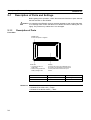
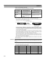
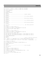
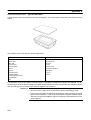
2-1-1
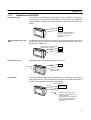
Description of Parts
Front View
POWER LED
Lit when the power is supplied.
POWER
RUN
RUN LED
S Lit when the unit is in
RUN mode.
S Flashes orange when the
battery voltage is low.
Display
An STN LCD screen with a backlight or an
EL screen. The whole area of the screen is
a touch panel which works as an input
device.
Battery Normal
RUN mode
Lit in green
Lit in orange
Other modes
Not lit
Lit in red
Reference The NT600S comes in two body colors.
S NT600S-ST121/ST211-EVj: beige
S NT600S-ST121B/ST211B-EVj: Black
24
Battery Abnormal
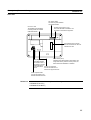
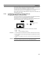
Description of Parts and Settings
Section 2-1
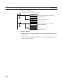
Rear View
DIP switch (SW2)
Set various system statuses
with these switches.
Lid of CFL case
The backlight unit and battery
mounting holder are installed
underneath this lid.
24 VDC
+
Contrast control (ST121 only)
Use a fine flat-blade screwdriver. Turn
clockwise to increase the brightness.
Host interface unit connector
Connect the cable from the host
interface unit here.
Reset switch (SW1)
Grounding terminal
Initializes the NT600S statuses. Note that for the
Grounding terminal
image data memory and the memory switch, the
for exclusive class 3
status before the initialization is retained.
grounding to prevent
malfunction due to
noise and electric Host I/F tool connector
shock.
Connect the cable from a
PC/Host or support tool here.
Power input terminals
Connect the power to the
NT600S at these terminals.
Reference Contrast control is available only for the following models:
S NT600S-ST121-EVj
S NT600S-ST121B-EVj
25
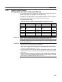
Description of Parts and Settings
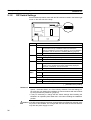
2-1-2
Section 2-1
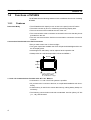
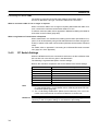
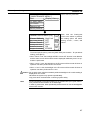
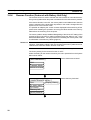
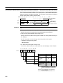
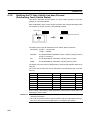
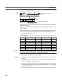
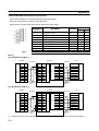
DIP Switch Settings
Set the NT600S operation status with the DIP switches located in the bottom right
corner on the rear side of the body.
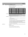
Switch #
SW2-1
SW2-2
SW2-3
SW2-4 to
SW2
SW2-7
Function
Screen data forced initialize effective/ineffective
ON
The NT600S will start in a special RUN mode in which the
screen data memory is initialized. When it is started, the
memory initialization menu will be displayed. For the initialization
procedure, refer to Section 3-4 Initializing Memory (page 72).
[OFF]
The NT600S will start in normal RUN mode.
Screen display language mode
[ON]
Messages are displayed in English.
OFF
Always set at ON.
Switching to the System Menu enabled/disabled
ON
The System Menu cannot be displayed. If an error occurs during
a start-up, the System Menu will be automatically displayed.
However, “RUN Mode” cannot be entered.
[OFF]
The System Menu can be displayed.
Not used.
ON
[OFF]
SW2-8
This switch must be set to the OFF position.
Low battery voltage detection effective/ineffective
ON
Low battery voltage is detected.
[OFF]
Low battery voltage is not detected.
[ ] indicates factory setting.
Reference S In addition to the DIP switches, set also the “Comm. Method”, “Host Link
Speed”, “Automatic Reset”, etc. at the memory switches. For these settings, refer to Section 3-6 “Setting the Conditions of Communications with the PC/Host
by Using the Memory Switches” (page 83)
S It may be necessary to change the DIP switch settings after installing the
NT600S in an operation panel. Bear this in mind when deciding the installation
position.
Caution If the DIP switch settings have been changed when the NT600S is powered, reset
the power to the NT600S. The changes with the DIP switches become effective
only after the power supply is reset.
26
Installation
2-2
Section 2-2
Installation
Install the NT600S to the operation panel and connect the power to the NT600S as
described below.
Caution Select a proper location referring to Appendix D Installation Environment (page
263).
Always switch OFF the power before assembling equipment or connecting
cables. Otherwise you could sustain an electric shock or equipment could be
damaged.
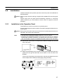
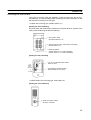
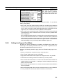
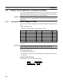
2-2-1
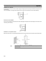
Installation to the Operation Panel
The NT600S can be flush mounted to an operation panel.
Use the panel fittings and tools included in the product package and follow the procedure below.
Caution During work at the panel, take care to ensure that no metal scraps enter the unit.
Otherwise, the product may malfunction.
Note
S The thickness of applicable operation panel is 1.6 mm to 4.8 mm.
S All fittings must be tightened uniformly to a torque of 0.5 to 0.6 Nm in order to
ensure water- and dust- resistance. The panel must not be soiled or warped,
and must be able to support an installation that will remain secure and strong.
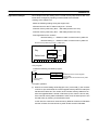
(1) Open a hole, shown below, in the panel and install the NT600S from the front
side of the panel.
180.5
263.5
+0.5 mm
0 mm
+0.5 mm
0 mm
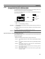
(2) Attach the panel fittings at four positions for the upper/lower sides and at two
positions for the right and left sides, shown below, on the rear side of the
NT600S.
Fit the hook of the fitting in the square hole in the body and tighten the screw
with a Phillips head screwdriver while lightly pulling the fitting.
27
Installation
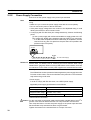
2-2-2
Section 2-2
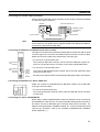
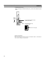
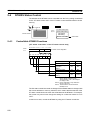
Power Supply Connection
Connect a 24 VDC power supply to the power input terminals.
Note
Use 2 mm2 or thicker wires to prevent voltage drop. Twist the wires together for
wiring.
S Make sure you connect the power supply wires with the correct polarity.
S Do not connect AC power to the DC terminals.
S If the power supply voltage does not conform to the stipulated rating, it could
destroy the terminal or burn internal circuits.
S If complying with EC directives (low voltage directives), observe the following
points:
(1) Use a power supply with reinforced insulation to supply power to the PT.
(2) If using the EL display type, embed the rear part of the PT in a control panel so that, after the product has been made ready for installation, the user
cannot touch any part of it apart from the part where PT operations are
performed (the front panel).
24 VDC
+
Breaker
24 VDC Power Supply
Reference When using an C200H direct communication the NT600S must be started up before the host. For details, refer to “Switching the Power ON/OFF When Using
C200H Direct” (page 62). When not using C200H direct communication, there are
no restrictions on the order in which power supplies are switched ON and OFF.
S Noise prevention
The NT600S has a noise preventive feature against the power supply line noise.
To further reduce noise, connect a noise filter to the power line. This will drastically reduce the ground noise.
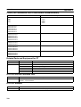
S Power supply
In order to comply with EC directives, use a SELV power supply.
Applicable power supply specifications are as follows.
Item
Value
Power supply voltage
24 VDC
Allowable power supply
voltage fluctuation range
20.4 VDC to 26.4 VDC
(24 VDC –15%, +10%)
Power supply capacity
ST121(B)-EVj 15W over
ST211(B)-EVj 25W over
S Parts used for connection
Caution For the connection to the power supply terminal block, twisted wires of 2 mm2 or
greater cross sectional area and M 3.5 size crimp terminals must be used.
Use crimp terminals to connect the power supply to the power input terminals.
Recommended crimp terminals for M3.5 are given below.
Tighten the screws on the terminal block to a torque of 0.8 N·m.
28
Installation
Section 2-2
Caution Fit crimp-style terminals to the power cable. Connecting the wires of the cable to
the terminal block directly after merely twisting them together could cause fire and
other hazards.
Fork type
7 mm or less
Round type
7 mm or less
[Recommended terminals]
Type
(fork type)
Type
(round type)
Japan Solderless Terminal MFG
2-YS3A
2-3.5
Fuji Terminal
2-YAS3.5
V2-S3.5
Nichifu Terminal
2Y-3.5
2-3.5
Maker
2-2-3
Applicable Wire
(stranded wire)
1.04 to 2.63 mm2
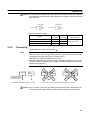
Grounding
The NT600S has a Grounding terminal
Note
NT600S
.
To prevent malfunctions due to excessive noise, and to prevent electric shock,
carry out class 3 grounding (grounding resistance of 100 W or less) using a special-purpose grounding cable (wire of at least 2 mm2).
Grounding wire length should be less than 20 m.
Note that if grounding wire is used in common with other equipment, or if it is connected to a beam of a building, for example, the NT600S might be adversely affected by this grounding.
Other
equipment
NT600S
Other
equipment
NT600S
Other
equipment
Class 3 grounding
(grounding resistance
is 100 Ω or less)
Grounding for individual equipment:…Correct
Grounding common to several pieces of equipment:…Incorrect
Caution Carry out class 3 grounding (grounding wire must be less than 100W) before connecting the power supply. Otherwise there will be a danger of electric shock.
29
Connecting to the Support Tool
2-3
Section 2-3
Connecting to the Support Tool
Connect the NT600S to a computer with an RS-232C cable to transfer the screen
data created by using a support tool to the NT600S.
In other than C200H direct communications, it is impossible to connect a computer
and the Host that are used to run the support tool at the same time. Connect a
computer only for transferring the screen data.
S Communication conditions
Communication conditions are set when a support tool is started.
Reference S It is impossible to connect a computer and a PC/Host at the same time to the
NT600S. Connect a computer only to transfer the screen data.
S To make a connector cable, refer to Appendix H Making the Cable for Connection to the Support Tool (page 281).
30
Connection to a PC by the Host Link
2-4
Section 2-4
Connection to a PC by the Host Link
Connect the NT600S to an OMRON PC by the host link method.
Reference To connect the NT600S to a PC by the host link method, the NT600S memory
switch for “Comm. Method” must be set for the host link. For the “Comm. Method”
setting, refer to “Selecting the Host Communication Method” (page 85).
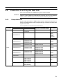
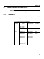
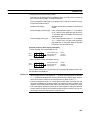
2-4-1
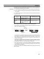
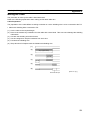
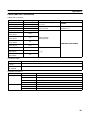
Compatible PCs
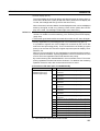
Some models and series of OMRON PCs have the host link function built in.
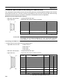
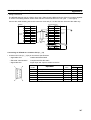
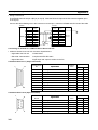
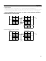
Check the model and series of the PC against the type of host link unit before making the connections.
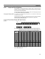
The compatible PCs are listed in the table below.
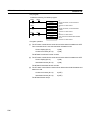
PC Series
Units with Built-in Host Link Function
Host Link Unit
CPU Unit
CPU Units Connectable Using an
Expansion Communication Board
C20H/C28H/
C40H/C60H
C series
Connectable to
CjjH
C120-LK201-V1
C120
C200H
C500 (F)
C1000H
C2000 (H)
C200H-LK201
C200H
C200H-LK201-V1
C200HS-CPU21-E
C200HS-CPU23-E
C200HS-CPU31-E
C200HS-CPU33-E
C200H-LK201-V1
C200HE-CPU42-E
C200HE-CPU32-E
C200HE-CPU42-E
C200HE
C200H-LK201-V1
C200HG-CPU43-E
C200HG-CPU63-E
C200HG-CPU33-E
C200HG-CPU43-E
C200HG-CPU53-E
C200HG-CPU63-E
C200HG
C200H-LK201-V1
C200HX-CPU44-E
C200HX-CPU64-E
C200HX-CPU34-E
C200HX-CPU44-E
C200HX-CPU54-E
C200HX-CPU64-E
C200HX
C500-LK201-V1
C500-LK203
C200HS
C500
C1000H
CQM1-CPU21-E
CQM1-CPU41-E
CQM1-CPU42-E
CQM1-CPU43-E
CQM1-CPU44-E
CQM1
CPM1-10CDR-j
CPM1-20CDR-j
CPM1-30CDR-j
CPM1
31
Connection to a PC by the Host Link
PC Series
CV series
i
(*)
CVM1 series
(*)
Section 2-4
Units with Built-in Host Link Function
Host Link Unit
CPU Units Connectable Using an
Expansion Communication Board
CPU Unit
Connectable to
CV500-LK201
CV500-CPU01-EV1
CV500
CV500-LK201
CV1000-CPU01-EV1
CV1000
CV500-LK201
CV2000-CPU01-EV1
CV2000
CV500-LK201
CVM1-CPU01-EV1
CVM1-CPU11-EV1
CVM1-CPU11-EV2
CVM1-CPU21-EV1
CVM1
* : Connection is not possible to the CPU units of CVM1/CV series PCs that do not have the suffix “-EVj”.
In the case of these CPU units, make the connection to NT600S by using a host link unit.
2-4-2
Connecting the NT600S
Refer to the illustrations below to select the appropriate cable for the unit connectors and connect the NT600S to the PC.
To make a connector cable, refer to Appendix E Method for Making the Cable for
Connection to the PC/Host (page 265).
Caution S After connecting a communication cable, always secure it with the screws.
Otherwise the cable may disconnect, causing operation to fail.
S The cable’s tensile load is 30 N. Do not subject it to loads greater than this.
Otherwise a discontinuity may occur, causing operation to fail.
Connecting to a PC with a 25-pin Connector
Use a connector cable with a 25-pin connector on one end and a 9-pin connector
on the other end (NT600S side) to connect the NT600S to a PC with a 25-pin connector.
NT600S
Host link unit/CPU unit
SYSMAC C series
PC, CVM1/CV
series PC
9-pin connector
Host I/F connector
(RS-232C 9-pin type)
25-pin connector
RS-232C connector cable
Use the following recommended cables (OMRON);
Connector
Specification
Type
Cable Length
XW2Z-200S
2m
XW2Z-500S
5m
25 pin to 9-pin
25-pin
9 pin
32
Applicable
Host Link Unit
C500-LK203
C500-LK201-V1
C120 LK201 V1
C120-LK201-V1
C200H-LK201
CV500-LK201
Connection to a PC by the Host Link
Section 2-4
Connecting to a PC with a 9-pin Connector
Use a connector cable with a 9-pin connector on both ends to connect the NT600S
to a PC with a 9-pin connector.
Host link unit/CPU unit
NT600S
SYSMAC C series
PC, CVM1/CV
series PC
9-pin connector
Host I/F connector
(RS-232C 9-pin type)
9-pin connector
RS-232C connector cable
The connector cable wiring for the C series CPU unit (CjjH) is different from that
for the other PCs. For details, refer to Appendix E Method for Making the Cable for
Connection to the PC/Host (page 265).
Note
Connecting the NT600S to a CVM1/CV Series Host Link Unit
Two types of connectors are provided to CV500-LK201 host link unit. Both of these
connector types can connect to the NT600S with an RS-232C connector cable.
Select the connector cable which matches the connector type.
S To connect to communication port 1
Communications
port 1
(RS-232C)
S To connect to communication port 2
I/O port
selector
switch
RS-232C
This is a 9-pin RS-232C/RS-422A connector. Use a connector cable with a 9-pin
connector on both ends.
↔
Communications
port 2
(RS-232C/
RS-422A)
This is a 25-pin RS-232C connector. Use a connector cable with a 25-pin connector on one end and a 9-pin connector on the other end (NT600S side).
Set the I/O port selector switch to the RS-232C side (upper side) to use this port.
RS-422A
Connecting the NT600S to a C Series CQM1 Unit
CQM1 can connect to the NT600S by the RS-232C method. Use an RS-232C
9-pin type connector cable.
S To connect to the RS-232C port
This is a 9-pin RS-232C connector. Use a connector cable with a 9-pin connector
on both ends.
Connecting to C Series C200HX/HG/HE
When using C series C200HX/HG/HE models, the NT600S can be connected to
the standard port of the CPU unit, or to ports A and B of the expansion communication board. Procure an RS-232C type connection cable for the connection. For
details on the specifications, installation method, etc., of the communication board
used for the connection, refer to the “SYSMAC C200HX/HG/HE Installation
Guide” (W302-E1-j).
33
Connection to a PC by the Host Link
Section 2-4
Connecting to C Series CPM1
The CPM1 is connected via an RS-232C adapter (type CPM1-CIF01).
Procure an RS-232C 9-pin type connection cable for the connection.
When a connector cable of 5 m or longer is required
When a connector cable of 5 m or longer is required, please make the cable. However, note that the maximum transmission distance is 15 m.
To make a connector cable, refer to Appendix E Method for Making the Cable for
Connection to the PC/Host (page 265).
When Long-Distance Transmission is Required
When transmission over a distance exceeding the RS-232C specification is required, it can be achieved by using an RS-232C/RS-422A converter unit (type NTAL001) to switch to RS-422A communication (RS-485 communication cannot be
used).
For details, refer to “Appendix F Connecting to an RS-232C/RS-422A converter
unit” (page 277 of the appendix).
2-4-3
PC Switch Settings
When the NT600S and PC are connected to each other, set the conditions at the
PC host link unit or the CPU as given in the table below.
The following is a general description of switch settings.
Refer to the manual for respective units for the details of the switch settings.
Item
Note
Switch Setting
I/O port
RS-232C
Baud rate
Set the same baud rate as the NT600S. (*1)
Transfer code
ASCII 7 data bits, 2 stop bits
Parity
Even
1-to-1/1-to-N
1-to-N (*2)
Instruction level
Level 1, 2, 3
Unit #
00
*1. Set the host link baud rate at 9600 bps or 19200 bps with the memory switch
for “host link baud rate”. For the details, refer to “Selecting the Host Link Communication Speed” (page 86).
*2. The 1-to-N setting enables BCC (Block Check Character). The 1-to-N connection cannot be used to connect the NT600S to a host link unit.
Reference When using CVM1/CV series, always set “CPU execution processing (execution
control 2)” in the PC system settings to “Simultaneous processing”.
34
Connection to a PC by the Host Link
Section 2-4
Connecting to a Host Link Unit
Two types of host link units are available: a rack-mounting type and a CPUmounted type. The switch settings differ according to the type of host link unit. Set
the switches according to the unit type.
S C200H rack-mounting type: C200H-LK201(-V1)
[Setting the front switches]
Set each switch with a flat blade screwdriver so that the values or symbols in the
setting value window agree with the following.
S Unit # (SW1, SW2)
Set these switches to “0”.
5
2
S Instruction level, parity, and transfer code (SW4)
Set this switch to “2”.
S Baud rate (SW3)
Set this switch to “5” to select 9600 bps.
Set this switch to “6” to select 19200 bps.
[Setting the rear switches]
S 1-to-1/1-to-N selection (DIP switch)
Set #3 to “ON”.
CTS
selector
switch
External
S CTS selection (selector switch)
Set this always to “0V” (ON).
0V (ON)
S C500/C1000H rack-mounting type: C500-LK201-V1
[Setting the front switches]
Host
Local
S Mode control (key switch)
Set this to “host link”.
35
Connection to a PC by the Host Link
Section 2-4
[Setting the rear switches]
S I/O port selection (selector switch)
Set this to “RS-232C”.
I/O port
RS-422A
RS-232C
S Unit # (DIP SW1)
Set SW1-1 to SW1-5 to “OFF” (“0”).
Synchronization
Internal
External
Termination
resistance
OFF
ON
CTS
0V
External
S Synchronization (selector switch)
Set this to “Internal”.
S Baud rate (DIP SW2-1 to SW2-4)
Set these switches to “1010” to select 9600 bps.
Set these switches to “0010” to select 19200 bps.
S 1-to-1/1-to-N selection (DIP SW2-6)
Set SW2-6 to “0” (1-to-N).
S Instruction level (DIP SW2-7, SW2-8)
Set these switches to “1”.
(Levels 1, 2, and 3 are enabled.)
S CTS selection (selector switch)
Set this always to “0V” (ON).
36
Connection to a PC by the Host Link
Section 2-4
S C500/C1000H rack-mounting type: C500-LK203
[Setting the rear switches]
S I/O port selection (selector switch)
Set this to “RS-232C”.
5V supply
ON
OFF
I/O port
RS-422A
RS-232C
Synchronization
Internal
External
Termination
resistance
OFF
ON
CTS
0V
External
S Unit #, parity, and transfer code (DIP SW1-1 to SW1-7)
Set SW1-1 to SW1-7 to “OFF” (“0”).
S Synchronization (selector switch)
Set this to “Internal”.
S Baud rate (DIP SW2-1 to SW2-4)
Set these switches to “1010” to select 9600 bps.
Set these switches to “0010” to select 19200 bps.
S 1-to-1/1-to-N selection (DIP SW2-6)
Set SW2-6 to “0” (1-to-N).
S Instruction level (DIP SW2-7, SW2-8)
Set these switches to “1”.
(Levels 1, 2, and 3 are enabled.)
S CTS selection (selector switch)
Set this always to “0V” (ON).
37
Connection to a PC by the Host Link
Section 2-4
S CPU-mounted type: C120-LK201-V1
[Setting the rear switches]
S Unit #, parity, and transfer code (DIP SW1-1 to SW1-5)
Set SW1-1 to SW1-5 to “OFF” (“0”).
* Parity is fixed at Even Parity. Transfer code is fixed
at ASCII 7 data bits and 2 stop bits.
S Baud rate (DIP SW2-1 to SW2-4)
Set these switches to “1010” to select 9600 bps.
Set these switches to “0010” to select 19200 bps.
S 1-to-1/1-to-N selection (DIP SW2-6)
Set SW2-6 to “0” (1-to-N).
S Instruction level (DIP SW2-7, SW2-8)
Set these switches to “1”.
(Levels 1, 2, and 3 are enabled.)
S CTS selection (DIP SW3-1 and SW3-2)
Set SW3-1 to “ON” (1) and SW3-2 to “OFF” (0).
(Set this always to “0V”.)
S Synchronization (DIP SW3-3 to SW3-6)
Set SW3-3, SW3-5, and SW3-6 to “ON” (1), and
SW3-4 to “OFF” (0). (Set these to “Internal”.)
38
Connection to a PC by the Host Link
Section 2-4
S CVM1/CV series backplate mounted type: CV500-LK201
[Setting the front switches]
Set the operating conditions with the PC System Setting functions when a
CVM1/CV series host link unit is connected to the NT600S. The PC system settings can be made directly from the peripheral tool (LSS etc.) or the PC system
setting information created with a peripheral tool can be transferred to the CPU.
The following describes the switch settings so as to enable the PC system settings. For the details of the PC system settings, refer to the “SYSMAC CVM1/CV
Series Support Software Operation Manual (Details)” (W196-E1-j).
S Unit # (SW3 and SW4)
Set these switches to “0”.
Communications
port 1
(RS-232C)
Communications
port 2
(RS-232C/
RS-422A)
I/O port
selector
switch
RS-232C
S I/O port selection (selector switch)
Set this to “RS-232C”.
S CTS selection (DIP SW2 and SW3)
Set SW2 or SW3 to “ON”. (Set this always to “0V”.)
To use communication port 1, set SW2.
To use communication port 2, set SW3.
↔
RS-422A
S PC system setting (DIP SW1)
Set SW1 to “OFF”.
Communication is performed in accordance with the
values set in the PC CPU special I/O unit system
settings. The initial values in the system settings
are as follows:
Baud rate
: 9600 bps
Parity
: Even
Xon/Xoff control : Not performed
Communication mode
: Full duplex
Stop bit
: 2 bits
Data length
: 7 bits
39
Connection to a PC by the Host Link
Section 2-4
Connecting to a CPU
S C-series CjjH, CVM1/CV-series (-EVj)
Reference Only CVM1/CV series CPU units designated “-EV1” or higher can be connected.
Set the operating conditions with the PC System Setting functions when a C
jj H, CVM1/CV-series host link unit is connected to the NT600S. The PC system settings can be made directly from the peripheral tool (LSS etc.) or the PC
system setting information created with a peripheral tool can be transferred to
the CPU.
The following describes the switch settings so as to enable the PC system settings. For the details of the PC system settings, refer to the “SYSMAC CjjH
User’s Manual (Programming)” (W176-E1-j) and the “SYSMAC CVM/CV-Series Support Software Operation Manual (Details)” (W196-E1-j).
(1) C-series CjjH
: C20H/C28H/C40H/C60H
No switch settings are required when connecting to a C-series CjjH CPU.
(2) CVM1/CV-series
: CV500-CPU01-EV1
CV1000-CPU01-EV1
CV2000-CPU01-EV1
CVM1-CPU01-EV1
CVM1-CPU11-EV1
CVM1-CPU11-EV2
CVM1-CPU21-EV1
Only CVM1/CV series CPU units designated “-EV1” or higher can be connected.
When connecting to a CVM1/CV-series CPU, set the switches as given below.
[Setting the front switches]
S I/O port selection (selector switch)
Set this to “RS-232C”.
I/O port
selector
switch
RS-232C
RS-422A
40
S System setting (DIP SW4)
To effect the existing DIP switch settings, set SW4 to “ON”.
To effect the existing PC system settings, set SW4 to “OFF”.
Note: In the case of CPU units manufactured before June
1995 (lot No. “jj65”), the factory settings of the DIP
switches do not agree with the factory settings for the
PC system settings.
S The factory settings for the DIP switches are:
2400 bps, 1 stop bit, even parity, 7-bits data length.
S The factory settings for the PC system settings are:
9600 bps, 2 stop bits, even parity, 7-bits data length.
For CPU units manufactured from July 1995 (lot No.
“jj75”) onward, the factory settings for the DIP
switches are also 9600 bps and 2 stop bits.
Connection to a PC by the Host Link
Section 2-4
[Making the PC system settings]
The possible settings and existing settings which can be set by the PC system setting are as given below.
Item
Possible Setting
Existing Setting
Baud rate
2400/4800/9600/19200 bps
9600 bps
Stop bit
1 or 2 stop bits
2 stop bits
Parity
Even/odd/non-parity
Even parity
Data length
ASCII 7 bits
ASCII 7 bits
Unit #
00 to 31
Unit #00
S C-series C200HS, C200HX/HG/HE, CPM1, CQM1
Set the operating conditions to the PC system setting area when a C200HS or
CQM1 CPU is connected to the NT600S. The PC system setting area (data
memory) can be directly accessed from the peripheral tool (LSS etc.).
The following describes the switch settings so as to enable the PC system settings. For the details of the operation with the PC system setting area, refer to the
“SYSMAC CQM1 Reference Manual” (W228-E1-j).
[Switch settings] (C200HS, C200HX/HG/HE, CQM1)
CPU unit DIP switch settings
S RS-232C port communication
condition settings
Set DIP switch 5 to OFF (right side)
to enable the PC system settings.
[Switch settings] (CPM1)
CPM1
-CIF01
CPM1
S Set the mode setting switch to
the “HOST” (upper) position.
[PC system setting area settings]
Write settings to the PC system setting area (data memory) according to the port
used to connect to the NT600S.
Channel #
Writing Value
DM6645
0001
Host link mode and conditions are set.
0303
Data length: 7 bits, 2 stop bits, even parity,
baud rate: 9600 bps
0304
Data length: 7 bits, 2 stop bits, even parity,
baud rate: 19200 bps
0000
Unit No. 0
DM6646
DM6648
Settings
41
Connection to a PC by the Host Link
Section 2-4
S When using port A of C200HX/HG/HE
Channel #
Writing Value
DM6555
0001
Host link mode
Set the conditions with the contents of DM.
0303
Data length: 7 bits, 2 stop bits, even parity,
baud rate: 9600 bps
0304
Data length: 7 bits, 2 stop bits, even parity,
baud rate: 19200 bps
0000
Unit No. 0
DM6556
DM6558
Settings
S When using port B of C200HX/HG/HE
Channel #
Writing Value
DM6550
0001
Host link mode
Set the conditions with the contents of DM.
0303
Data length: 7 bits, 2 stop bits, even parity,
baud rate: 9600 bps
0304
Data length: 7 bits, 2 stop bits, even parity,
baud rate: 19200 bps
0000
Unit No. 0
DM6551
DM6553
Settings
S When using CPM1
Channel #
Writing Value
DM6650
0001
Host link mode
Set the conditions with the contents of DM.
0303
Data length: 7 bits, 2 stop bits, even parity,
baud rate: 9600 bps
0304
Data length: 7 bits, 2 stop bits, even parity,
baud rate: 19200 bps
0000
Unit No. 0
DM6651
DM6653
42
Settings
Connection to a PC by the NT Link (1:1)
2-5
Section 2-5
Connection to a PC by the NT Link (1:1)
Connect the NT600S to an OMRON PC by the NT link method.
Reference To connect the NT600S to a PC by the NT link method, the NT600S memory
switch for “host communication” must be set for the NT link. For the “host communication” setting, refer to “Selecting of the Host Communication Method” (page
85).
2-5-1
Compatible PCs
With OMRON PCs, the unit that has the built-in NT link function varies depending
on the models and series. For C200HX/HG/HE, the CPU unit to be connected in
the NT link by adding a communication board is available.
Check the model and series of the PC against the type of host link unit before making the connections.
The compatible PCs are listed in the table below.
PC Series
C series
CV series
CVM1 series
CPU Unit
CPU Units Connectable
Using an Expansion
Communication Board
Connectable to
CQM1-CPU41-E
CQM1-CPU42-E
CQM1-CPU43-E
CQM1-CPU44-E
CQM1
C200HS-CPU21-E
C200HS-CPU23-E
C200HS-CPU31-E
C200HS-CPU33-E
C200HS
C200HE-CPU42-E
C200HE-CPU32-E
C200HE-CPU42-E
C200HE
C200HG-CPU43-E
C200HG-CPU63-E
C200HG-CPU33-E
C200HG-CPU43-E
C200HG-CPU53-E
C200HG-CPU63-E
C200HG
C200HX-CPU44-E
C200HX-CPU64-E
C200HX-CPU34-E
C200HX-CPU44-E
C200HX-CPU54-E
C200HX-CPU64-E
C200HX
CV500-CPU01-EV1
CV500
CV1000-CPU01-EV1
CV1000
CV2000-CPU01-EV1
CV2000
CVM1-CPU01-EVj
CVM1-CPU11-EVj
CVM1-CPU11-EVj
CVM1-CPU21-EVj
CVM1
43
Connection to a PC by the NT Link (1:1)
2-5-2
Section 2-5
Connecting the NT600S
Refer to the illustrations below to select the appropriate cable for the unit connectors and connect the NT600S to the PC.
A host link connector cable can also be used. To make a connector cable, refer to
Appendix E Method for Making the Cable for Connection to the PC/Host (page
265).
Caution S After connecting a communication cable, always secure it with the screws.
Otherwise the cable may disconnect, causing operation to fail.
S The cable’s tensile load is 30 N. Do not subject it to loads greater than this.
Otherwise a discontinuity may occur, causing operation to fail.
Note
Before inserting or removing the connectors, make sure that the NT600S and the
PC are turned OFF.
Use a connector cable with a 9-pin connector on both ends to connect the NT600S
to a PC with a 9-pin connector.
NT600S
CPU unit
SYSMAC C series
PC, CVM1/CV
series PC
9-pin connector
Host I/F connector
(RS-232C 9-pin type)
9-pin connector
RS-232C connector cable
The following are the recommended cables (manufactured by OMRON).
Connector Specification
9pin 9pin
Model
Cable Length
XW2Z-200T
2m
XW2Z-500T
5m
If a Cable Longer Than 5 m is Required
If a cable longer than 5 m is required, a connector cable will have to be made. Refer
to Appendix E Method for Making the Cable for Connection to the PC/Host (page
265).
The maximum transmission distance is 15 m.
When Long-Distance Transmission is Required
When transmission over a distance exceeding the RS-232C specification is required, it can be achieved by using an RS-232C/RS-422A converter unit (type NTAL001) to switch to RS-422A communication (RS-485 communication cannot be
used).
For details, refer to “Appendix F Connecting to an RS-232C/RS-422 Converter
Unit” (page 277 of the appendix).
44
Connection to a PC by the NT Link (1:1)
2-5-3
Section 2-5
PC Switch Settings
When the NT600S and PC are connected to each other, set the conditions at the
PC CPU so as to enable the NT link communications.
The following is a general description of switch settings.
S C-series C200HS, C200HX/HG/HE, CPM1, CQM1
Set the operating conditions to the PC system setting area when a C200HS or
CQM1 CPU is connected to the NT600S. The PC system setting area (data
memory) can be directly accessed from the peripheral tool (LSS etc.).
The following describes the switch settings so as to enable the PC system settings. For the details of the operation with the PC system setting area, refer to the
“SYSMAC CQM1 Reference Manual” (W228-E1-j).
[Switch setting] (C200HS, C200HX/HG/HE, CQM1)
CPU unit DIP switch settings
S RS-232C port communication
condition settings
Set DIP switch 5 to OFF (right side)
to enable the PC system settings.
[PC system setting area settings] (C200HX/HG/HE, CPM1, CQM1)
Write values to the PC system setting area (data memory) in accordance with the
CPU unit and port used for connection to the NT600S.
PC Side
Channel #
RS-232 port of
C200HX/HG/HE,
CQM1
DM6645
Port A of C200HX/
HG/HE
DM6555
Port B of C200HX/
HG/HE
DM6550
CPM1
DM6650
Writing Value
4000
Settings
Use NT link (1:1)
45
Connection to a PC by the NT Link (1:1)
Section 2-5
S CVM1/CV-series (-EVj)
When connecting to a CVM1/CV-series (-EVj) CPU, set the switches as given
below.
I/O port
selector
switch
RS-232C
S I/O port selection (selector switch)
Set this to “RS-232C”.
RS-422A
D
D
D
D
D
D
ON 1 2 3 4 5 6
S NT link setting (DIP SW3)
Set SW3 to “ON”.
Set SW3 to “ON” (right).
OFF ↔ ON
[Setting Information]
When connecting to a CVM1/CV-series, set ”Execute control 2,” ”Execute process” of the PC Setup to ”Synchronous.”
46
Connection to a PC by the NT Link (1:N)
2-6
Section 2-6
Connection to a PC by the NT Link (1:N)
Connect the NT600S to an OMRON PC by the NT link method.
To connect the NT600S to a PC by the NT link (1:N) method, the communication
conditions must be set with the memory switches.
S Setting NT link (1:N)
(Refer to “Selecting the Host Communication Method” (page 85))
S Setting the unit No. of the connected NT20S
(Selecting Unit Numbers (page 87))
2-6-1
Compatible PCs
The only OMRON PCs that can be connected in an NT link (1:N) are the C series
C200HX/HG/HE models. When making a connection, check the series and model
of the PC to which the connection is being made, and the type of host link unit that
is installed.
The following is a list of the PCs that can be connected to the NT600S via a host
link (1:N).
PC Series
C series
2-6-2
CPU Units Connectable
Using an Expansion
Communication Board
Connectable to
C200HE-CPU42-E
C200HE-CPU32-E
C200HE-CPU42-E
C200HE
C200HG-CPU43-E
C200HG-CPU63-E
C200HG-CPU33-E
C200HG-CPU43-E
C200HG-CPU53-E
C200HG-CPU63-E
C200HG
C200HX-CPU44-E
C200HX-CPU64-E
C200HX-CPU34-E
C200HX-CPU44-E
C200HX-CPU54-E
C200HX-CPU64-E
C200HX
CPU Unit with Built-in
NT Link Function
Connecting the NT600S Units
Referring to the illustrations below and using a cable appropriate for the CPU unit’s
connector, connect the NT600S units and the PC using RS-232C/RS-422A converter units (type NT-AL001).
An NT link connection cable can be used as the RS-232C cable. For details on
making a connection cable, refer to Appendix E “Method for Making the Cable for
Connection to the Host” (page 265).
Caution S After connecting the communication cable, be sure to lock the connectors with
the screws.
Otherwise the cable may disconnect, causing operation to fail.
S The cable’s tensile load is 30 N. Do not subject it to loads greater than this.
Otherwise a discontinuity may occur, causing operation to fail.
47
Connection to a PC by the NT Link (1:N)
Section 2-6
Connection Diagram
As shown in the figure below, connect multiple NT600S units to one PC. In an NT
link (1:N), up to eight NT600S units can be connected to one PC port.
C200HX/HG/HE
OMRON PC
(*1) Total cable length: 500 m
While controlling machinery and
monitoring lines, controls the
NT600S units when necessary.
C200HX/HG/HE can be used.
(*2) For connection to an
NT600S-ST121(B)-EV3, a
separate power supply is
required.
RS-232C cable
(max. length: 2 m), or
directly connected
RS-422A/485 cable
RS-232C/RS-422A
converter unit,
type NT-AL001
RS-422A/485 cable (*1)
RS-232C/RS-422A converter
unit, type NT-AL001
(Not required if the connection is
made at the RS-422A/485 port.)
RS-232C/RS-422A
converter unit,
type NT-AL001
RS-422A/485 cable (*1)
+5V (*2)
(150 mA)
RS-232C cable
(max. length: 2 m)
NT600S
+5V (*2)
(150 mA)
RS-232C cable
(max. length: 2 m)
NT600S
(Up to eight NT600S units can be connected.)
[Maximum Number of NT600Ss Connectable to One Port]
The maximum number of NT600S units that can be connected to the RS-232C
port (built in the CPU) and the A and B ports in the communication board is indicated below.
S C200HE
:Up to 4 NT600S units per port (unit Nos. 0 to 3)
S C200HG, C200HX
:Up to 8 NT600S units per port (unit Nos. 0 to 7)
Reference S When NT600S-ST121(B)-EV3 is connected in the configuration shown in the
figure above, a separate +5 V (150 mA) power supply is required to drive the
RS-232C/RS-422 converter units (NT-AL001). When NT600S-ST211(B)-EV3
is connected, the power to the converter unit can be supplied from the PT itself,
so no separate power supply is required.
S When connecting the C200HX/HG/HE and an RS-232C/RS-422A converter
unit, use a converter unit whose lot number is 15Y5 or later. Converter units of
lot numbers previous to 15Y5 cannot be connected.
48
Connection to a PC by the NT Link (1:N)
Section 2-6
Converter Unit Connector Specifications
The terminal block specifications of the RS-232C/RS-422A converter unit are indicated here. For details on the method for making the connection cable, refer to
“Making the Cable” (page 273).
NT-AL001 RS-422A terminal block specifications
S Connected terminal block RS-422A terminal block (M3 screws)
S Electrical characteristics
Conform to EIA RS-422A
S Signal direction
Signal input and output is relative to the NT-AL001.
Terminal
Block Pin
No.
Signal Direction
Signal Name
Abbreviation
Input
Output
8
Request to send ()
CSA
7
Request to send ()
CSB
6
Receive data ()
RDA
5
Receive data ()
RDB
4
Send data ()
SDA
3
Send data ()
SDB
2
Signal ground
SG (GND)
1
Functional ground
* The CSA and CSB signals are for special applications.
Converter Unit Terminal Screws and Crimp Terminals
The terminal screws are M3 screws. Use M3 size crimp terminals. Tighten the terminal screws with a torque of 0.5 N·m.
Note
During wiring, crimp terminals must be used for connections.
[Recommended crimp terminals]
Fork Type
6.2mm or less
Maker
Round Type
6.2mm or less
Type
Japan Solderless
Terminal MFG
1.25-N3A (Fork)
Molex
Y1.25-3.5L (Fork)
Recommended Wire Size
AWG22 to 18 (0.3 to 0.75mm2)
49
Connection to a PC by the NT Link (1:N)
Section 2-6
Wiring Method
For the connections between the PC and NT600S units, wire as shown below. The
wiring method differs depending on the cables used for connection.
S RS-422A connection
C200HX/HG/HE
OMRON PC
While controlling machinery and
monitoring lines, controls the
NT600S units when necessary.
C200H/HG/HE can be used.
RS-232C cable
(max. length: 2 m),
or directly
connected RS-422A
cable
RS-232C/RS-422A
converter unit,
type NT-AL001
RS-422A cable (*)
RS-232C/RS-422A
converter unit,
type NT-AL001
RS-232C/RS-422A
converter unit,
type NT-AL001
RS-422A cable (*)
(1)
NT600S
RS-422A cable (*)
RS-232C cable
(max. length: 2 m)
NT600S
RS-232C/RS-422A
converter unit,
type NT-AL001
RS-422A cable (*)
(2)
(2)
RS-232C cable
(max. length: 2 m)
RS-232C/RS-422A
converter unit,
type NT-AL001
(2)
RS-232C cable
(max. length: 2 m)
RS-232C cable
(max. length: 2 m)
NT600S
NT600S
(*) Total cable length: 500 m
[RS-232C Cable Wiring] (NT600S-ST211(B)-EVj)
PT, PC
NT-AL001
Abbrev.
RS-232C
interface
SD
RD
RS
CS
+5V
SG
Pin No.
Pin No.
Connector
cover
Connector
cover
2
3
4
5
6
9
2
3
4
5
6
9
Shielding
wire
Abbrev.
SD
RD
RS
CS
+5V
SG
RS-232C
interface
: Only connected at PC
The pin numbers are the numbers at the NT600S.
For the pin numbers at the PC, refer to the manual for the PC used.
50
Connection to a PC by the NT Link (1:N)
Section 2-6
[RS-232C Cable Wiring] (NT600S-ST121(B)-EVj)
PT, PC
NT-AL001
Abbrev.
RS-232C
interface
Pin No.
Pin No.
Connector
cover
Connector
cover
2
3
4
5
6
9
2
3
4
5
6
9
SD
RD
RS
CS
+5V
SG
+5V
(150 mA)
Shielding
wire
Abbrev.
SD
RD
RS
CS
+5V
SG
RS-232C
interface
: Only connected at PC
The pin numbers are the numbers at the NT600S.
For the pin numbers at the PC, refer to the manual for the PC used.
[RS-422A Cable Wiring (1)]
S RS-232C connection at the PC side
NT-AL001
RS-422A
terminal
block
NT-AL001
Abbrev.
Pin No.
Pin No.
Abbrev.
Functional
ground
1
1
Functional
ground
SDB
SDA
RDB
RDA
3
4
5
6
3
4
5
6
SDB
SDA
RDB
RDA
RS-422A
terminal
block
Shielding
wire
S RS-422A connection at the PC side
PC
NT-AL001
Abbrev.
RS-422A
interface
Pin No.
Abbrev.
Connector
cover
1
Functional
ground
SDA (–)
SDB (+)
RDA (–)
RDB (+)
3
4
5
6
SDB
SDA
RDB
RDA
RS-422A
terminal
block
Shielding
wire
[RS-422A Cable Wiring (2)]
NT-AL001
NT-AL001
Abbrev.
RS-422A
terminal
block
Pin No.
Pin No.
Abbrev.
Functional
ground
1
1
Functional
ground
SDB
SDA
RDB
RDA
3
4
5
6
3
4
5
6
SDB
SDA
RDB
RDA
RS-422A
terminal
block
Shielding
wire
51
Connection to a PC by the NT Link (1:N)
Section 2-6
S RS-485 connection
C200HX/HG/HE
OMRON PC
While controlling machinery and
monitoring lines, controls the
NT600S units when necessary.
C200H/HG/HE can be used.
RS-232C cable
(max. length: 2 m), or
directly connected
RS-485 cable
RS-232C/RS-422A
converter unit,
type NT-AL001
RS-485 cable (*)
RS-232C/RS-422A
converter unit,
type NT-AL001
RS-485 cable (*)
RS-232C/RS-422A
converter unit,
type NT-AL001
RS-485 cable (*)
RS-232C cable
(max. length: 2 m)
NT600S
RS-232C/RS-422A
converter unit,
type NT-AL001
RS-232C cable
(max. length: 2 m)
NT600S
RS-232C/RS-422A
converter unit,
type NT-AL001
RS-485 cable (*)
RS-232C cable
(max. length: 2 m)
NT600S
RS-232C cable
(max. length: 2 m)
NT600S
(*) Total cable length: 500m
[RS-232C Cable Wiring]
Same as for an RS-422A connection. Refer to “RS-422A connection” (page 50).
[RS-485 Cable Wiring]
S NT-AL001 to NT-AL001
NT-AL001
NT-AL001
Abbrev.
RS-422A
terminal
block
Functional
ground
SDB
SDA
RDB
RDA
Pin No.
Pin No.
Abbrev.
1
1
Functional
ground
3
4
5
6
3
4
5
6
SDB
SDA
RDB
RDA
RS-422A
terminal
block
Shielding
wire
S PC to NT-AL001
PC
NT-AL001
Pin No.
Abbrev.
Connector
cover
1
Connector
cover
SDA (–)
SDB (+)
3
4
SDB
SDA
Abbrev.
RS-422A
interface
Shielding
wire
52
RS-422A
terminal
block
Connection to a PC by the NT Link (1:N)
Section 2-6
NT-AL001 Converter Unit DIP Switch Settings
The DIP switch settings to be made at an NT-AL001 used in the wiring depend on
whether it is connected part way along the RS-422A/485 cable or is at the end of
the RS-422A/485 cable.
S RS-422A connection, RS-232C at the PC side
C200HX/HG/HE
RS-232C cable
(max. 2 m)
RS-232C/RS-422A
converter unit,
type NT-AL001
(Termination)
RS-232C/RS-422A
converter unit,
type NT-AL001
RS-232C/RS-422A
converter unit,
type NT-AL001
RS-422A cable (*)
RS-422A cable (*)
RS-232C cable
(max. 2 m)
(Termination)
NT600S
RS-232C cable
(max. 2 m)
NT600S
RS-232C/RS-422A
converter unit,
type NT-AL001
RS-232C cable
(max. 2 m)
NT600S
(*) Total cable length: 500 m
S RS-485 connection, RS-232C at the PC side
C200HX/HG/HE
RS-232C cable
(max. 2 m)
RS-232C/RS-422A
converter unit,
type NT-AL001
RS-232C/RS-422A
converter unit,
type NT-AL001
RS-232C/RS-422A
converter unit,
type NT-AL001
RS-485 cable (*)
RS-485 cable (*)
RS-232C cable
(max. 2 m)
(Termination)
NT600S
RS-232C cable
(max. 2 m)
NT600S
NT600S
(Termination)
RS-232C/RS-422A
converter unit,
type NT-AL001
RS-232C cable
(max. 2 m)
(*) Total cable length: 500m
53
Connection to a PC by the NT Link (1:N)
Section 2-6
S RS-422A connection, RS-422A at the PC side
C200HX/HG/HE
RS-422A
cable (*)
(Termination)
(Termination)
RS-232C/RS-422A
converter unit,
type NT-AL001
RS-232C/RS-422A
converter unit,
type NT-AL001
(Communication board)
RS-422A cable (*)
RS-232C cable
(max. 2 m)
RS-232C cable
(max. 2 m)
RS-232C/RS-422A
converter unit,
type NT-AL001
RS-232C cable
(max. 2 m)
(*) Total cable length: 500 m
NT600S
NT600S
NT600S
RS-485 connection, RS-485 at the PC side
C200HX/HG/HE
RS-485
cable (*)
(Termination)
RS-232C/RS-422A
converter unit,
type NT-AL001
RS-232C/RS-422A
converter unit,
type NT-AL001
(Termination)
(Communication board)
RS-485 cable (*)
RS-232C cable
(max. 2 m)
RS-232C cable
(max. 2 m)
RS-232C/RS-422A
converter unit,
type NT-AL001
RS-232C cable
(max. 2 m)
(*) Total cable length: 500 m
NT600S
54
NT600S
NT600S
Connection to a PC by the NT Link (1:N)
2-6-3
Section 2-6
PC Switch Settings
When the PC and NT600S units have been connected, set the switches at the
CPU module at the PC side in order to enable communication using the NT link
method.
S C series, C200HX/HG/HE
Write the communication conditions directly to the “PC system area” (data
memory) using a peripheral tool (e.g., SYSMAC support software). For details on
the operation for setting the “PC system area”, refer to the “SYSMAC C200HX/
HG/HE Installation Guide” (W302-E1-j).
[PC system setting area setting]
With C200HX/HG/HE, the setting area differs according to the standard port of the
CPU module used for the connection or the port of the expansion communication
board.
Port
Channel #
C200HX/HG/HE
RS-232C port
DM6645
C200HX/HG/HE
port A
DM6555
C200HX/HG/HE
port B
DM6550
Writing Value
5j00
Settings
Use NT link (1:N)
j = highest unit No.
No
in the maximum
number of connect
connectable PTs (1 to 7). (*)
(*) When using C200HE, the PT unit No. range is 1 to 3.
55
Connecting to the PC with C200H Direct Communication
2-7
Section 2-7
Connecting to the PC with C200H Direct Communication
This is the procedure for connecting the NT600S to an OMRON PC by using the
C200H direct communication method.
2-7-1
Compatible PCs
Some models and series of OMRON PCs have the direct communication function
built in. Check the model and series of the PC to which the connection is to be
made, and the type of CPU unit installed before making the connections.
The PCs that can be connected to the NT600S by using C200H direct communication are listed below.
CPU Unit
C20H/C28H/C40H/C60H
Model Name
CjjH
C200H-CPU01-E
C200H-CPU03-E
C200H-CPU11-E
C200H-CPU21-E
C200H
C200H-CPU23-E
C200H-CPU31-E
C200HS-CPU01-E
C200HS-CPU03-E
C200HS-CPU21-E
C200HS-CPU23-E
C200HS
C200HS-CPU31-E
C200HS-CPU33-E
C200HE-CPU11-E
C200HE-CPU32-E
C200HE
C200HE-CPU42-E
C200HG-CPU33-E
C200HG-CPU43-E
C200HG-CPU53-E
C200HG
C200HG-CPU63-E
C200HX-CPU34-E
C200HX-CPU44-E
C200HX-CPU54-E
C200HX
C200HX-CPU64-E
Caution In a system where the user program operates according to the PC cycle time, the
system operation may not be constant because of cycle time fluctuations.
Consider this point when designing the system.
56
Connecting to the PC with C200H Direct Communication
Section 2-7
C200H Interface Unit Part Names and Functions
This section gives the names and functions of the parts of the C200H interface unit
for your information before you mount the C200H interface unit to the NT600S.
C200H interface unit: NT-LB122
Front of C200H interface unit
Switch cover
Covers the rotary and DIP switches used to
set the basic operations of the C200H
interface unit.
Host interface connector
The cable from the PC is connected here.
Reference When the C200H interface unit is mounted or removed from the NT600S, the
memory switches are initialized.
Mounting and Setting the C200H Interface Unit
This section explains how to mount the C200H interface unit on the NT600S, and
how to set the DIP switches.
Mounting the Unit to the NT600S
Mount the C200H interface unit by inserting it fully home so that there is no clearance between it and the NT600S, then tightening the screws securely.
If it is difficult to make the connection, shift the position of the unit and try inserting it
again.
Note
Be sure to switch off the power to the NT600S before mounting or removing the
unit.
57
Connecting to the PC with C200H Direct Communication
Removing the unit
Section 2-7
As shown in the figure below, grasp the unit by the cutouts at either side, then pull it
out while keeping a firm grip.
C200H Interface Unit Switch Settings
Set all the DIP switches (SW1, SW2) of the C200H interface unit to “OFF” (reserved for system use) and set the unit number to 0 with the rotary switch (SW3).
It is necessary to set a machine number for NT600S since it operates as a highlevel function I/O unit of C200H. Make sure that the machine number to be allocated is unique.
Switch cover
SW1
SW2
SW3
The DIP switches are located under the switch cover
on the front of the interface unit.
When using C200H/HS, or C200HX/HG/HE, the words corresponding to the
channel numbers indicated below are occupied for each unit number set. However, since the NT600S uses the allocated bits and words for processing, it does not
use these words.
These words are used as internal auxiliary relays.
Unit No.
Channel #
0
100 to 109
1
110 to 119
2
120 to 129
3
130 to 139
4
140 to 149
5
150 to 159
6
160 to 169
7
170 to 179
8 (*)
180 to 189
9 (*)
190 to 199
(*) Cannot be set with CjjH.
58
Connecting to the PC with C200H Direct Communication
Section 2-7
Reference S If unit numbers 8 and 9 are set with a CjjH, a “special I/O unit error” occurs.
S When an NT600S is connected to a CjjH, I/O expansion equipment cannot
be connected. In other words, it will not be possible to connect other special I/O
units, and therefore whatever unit numbers are specified there will be no duplication of numbers.
2-7-2
Connection Method
Using the I/O connecting cable, connect the C200H interface unit mounted to the
NT600S and the PC unit.
Caution S Always turn off the power at both the PC and PT before connecting the C200H
interface cable.
Otherwise the system may operate unpredictably.
S Switch off the power to the NT600S and PC before disconnecting/connecting
the cable.
[I/O connecting cable]
Use one of the following models of I/O connecting cable.
Model
For connecting C200H/
HS/HE/HG/HX
For connecting CjjH
Cable length (L)
C200H-CN311
30 cm
NT20M-CNP711
C200H-CN711
70 cm
NT20M-CNP221
C200H-CN221
2m
NT20M-CNP521
C200H-CN521
5m
NT20M-CNP131
C200H-CN131
10 m
C20H-CN312
30 cm
NT20M-CNP712
C20H-CN712
70 cm
NT20M-CNP222
C20H-CN222
2m
In the case of NT20M-CNPjjj models, the connector at the C200H interface
side is a compact one.
Caution S The combined lengths of each of the I/O connecting cables must not exceed a
total of 12 m (or 6 m for CjjH models).
S The cable’s tensile load is 30 N. Do not subject it to loads greater than this.
Otherwise a discontinuity may occur, causing operation to fail.
Note
S If the I/O connecting cable is passed through a hole, this hole must have a diameter of at least 53 mm ø. If the top cover is removed the cable can be passed
through a minimum hole size of 33 mm ø. Replace the cover before mounting
the unit.
S If a C200H-CNjjj or C20H-CNjjj is used as the I/O connection cable,
the connector will project beyond the bottom face of the NT600S.
59
Connecting to the PC with C200H Direct Communication
Section 2-7
Connection to a C200H/C200HS, C200HX/HG/HE
Make the connection to the CPU unit or I/O extension unit with an I/O connecting
cable. The following restrictions apply to this connection:
S Only one CPU unit, and one I/O extension unit, can be connected. Connection to
two I/O extension units is not possible.
S Connection to remote I/O slave units is not possible.
S The C200H interface unit only has one interface connector. It is not possible to
connect a C200H interface unit between a CPU unit and an I/O extension unit. It
must be connected as the final element in the system.
CPU unit
I/O connection cable
(C200H-CNjj1)
I/O extension unit
Max. 1 unit
(Rear face of NT600S)
I/O extension cable
(NT20M-CNPjj1/
C200H-CNjj1)
60
C200H I/F unit
Connecting to the PC with C200H Direct Communication
Connection to a CjjH
Section 2-7
Make the connection to the CPU unit with an I/O connecting cable. The following
restrictions apply to this connection.
S Only one CPU unit can be connected.
S Up to two I/O units can be connected to one CPU unit. However, it is not possible
to connect an I/O extension unit.
S It is not possible to connect a CjjH I/O unit after a C200H interface unit. The
C200H interface unit must be the final element in the system.
CPU unit
I/O connection cable
(C20H-CNjj2)
I/O unit
I/O connection cable
(C20H-CNjj2)
I/O unit
Max. 2 units
(Rear face of NT600S)
C200H I/F unit
I/O extension cable
(C20M-CNPjj2/
C20H-CNjj2)
Note
When making a connection to a CjjH, a noise filter must be installed.
1. Insert the noise filter in the power supply line of the CjjH.
2. Make the distance between the noise filter and the CjjH as short as possible, and separate it from the power supply line.
3. Connect the case of the noise filter to the FG face.
4. For the noise filter, use a ZGB2202-01U made by TDK or equivalent.
Noise filter
1
+24V
2
4
IN
OUT
3
+
24V
–
61
Connecting to the PC with C200H Direct Communication
Section 2-7
Switching the power ON/OFF when using C200H direct communication
The C200H interface unit has the function of a C200H I/O extension unit. The power should be switched ON/OFF in the way explained below.
Caution Depending on how the power is switched ON/OFF, the entire system may stop.
Follow the correct procedure when switching the power ON/OFF.
Otherwise the system may operate unpredictably.
Power ON
Switch the power ON in the following sequence.
Switch the NT600S power ON . . . . . . “Connecting to Host” will be displayed on
the NT600S screen.
Switch the PC power ON
. . . . . . After “Connecting to Host” has been displayed on the NT600S screen for approximately 1 second, normal operation
starts.
Reference S If the power supply to the PC/Host is switched on first, the CPU of the PC/Host is
subject to a system reset, disabling PC/Host operation. If the power to the
NT600S is then switched ON, “Connecting to Host” will be displayed on the
NT600S screen for approximately one second and then normal operation will
commence.
S If the I/O connecting cable is disconnected during system operation, an I/O bus
error will occur at the PC/Host side and operation will stop. If this happens, connect the I/O connecting cable and clear the error.
Power OFF
Switch the power OFF in the following way.
Switch the PLC and NT600S . . . . . . The next time the power is switched ON,
power supplies OFF simultathe NT600S will display the screen that
neously
was being displayed when it was
switched OFF.
Reference S If the power supply to the NT600S is switched OFF first, the CPU of the PC/Host
is subject to a system reset, disabling PC operation.
S The system must be stopped before replacing a defective NT600S or C200H
interface unit. If only the power to the NT600S is switched OFF, the system will
stop suddenly, causing accidents or damage to machinery.
62
Host Connections by RS-232C
2-8
Section 2-8
Host Connections by RS-232C
Connect NT600S with an RS-232C Interface Unit installed to the host computer
with an RS-232C cable.
RS-232C connection allows a single NT600S to be connected to the host.
A computer or other control device with a built-in RS-232C interface is a suitable
host for connection to the NT600S.
Reference To connect the NT600S to a Host by the RS-232C method, the NT600S memory
switch for “Comm. Method” must be set to “RS-232C” and the communication settings must be set for RS-232C communications. For the “Comm. Method” setting,
refer to “Selecting the Host Communication Method” (page 85), and for the
memory switch setting for RS-232C communication, refer to “Setting the
RS-232C Communication Conditions” (page 89).
2-8-1
Host Computer Communication Settings
Set the host communication conditions according to the following table.
Item
Baud rate
Setting
Data bits
Set to the same baud rate as the NT600S: 2400, 4800, 9600,
19200
7 bits/8 bits
Stop bits
1 bit/2 bits
Parity
Even, Odd, None
Flow control
RS/CS control
XON/XOFF control
None
Reference Set the same communication conditions at the NT600S and Host.
Refer to the appropriate instruction manuals for the method of setting the Host
communication conditions.
You are recommended to set the maximum baud rate supported by both the
NT600S and Host.
2-8-2
Connector Pin Arrangement
The RS-232C connection between the NT600S and Host is described below.
RS-232C Interface Unit
The connector and cable specifications are described below.
Electrical characteristics: Conforms to EIA RS-232C specifications.
Signal direction: Signal input and output are relative to the host computer.
1
5
6
9
63
Host Connections by RS-232C
Section 2-8
Connector pin
i #
Abbreviation
i
1
Frame ground
FG
Signal direction
Input
Output
-----
2
Send data
SD (TXD)
---
Yes
3
Receive data
RD (RXD)
Yes
---
4
Request to send
RS (RTS)
---
Yes
5
Clear to send
CS (CTS)
Yes
---
6
+5V 150 mA Max. (ST211(B)-EVj)
100 mA Max. (ST121(B)-EVj)
Signal ground
+5 V
---
Yes
SG (GND)
---
---
9
Note
Signal
g
name
1. FG is not connected internally in the NT600S.
2. Unlisted pins are not used.
For cable parts and the wiring method, refer to APPENDIX E Method for Making
the Cable for Connection to the PC/Host (page 265).
Connecting to the Host Computer
Use a cable that is compatible with the RS-232C connector of the host to connect
the NT600S and the host.
In the example shown here, the cable connects the 9-pin connector of the NT600S
and 25-pin connector of the host. If the host has a 9-pin RS-232C connector, use
an RS-232C cable with 9-pin connectors at both ends.
NT600S
9-pin
connector
Host Interface connector
(RS-232C, 9-pin type)
25-pin
connector
RS-232C cable
Caution S Turn off the NT600S power supply when connecting or disconnecting connectors.
S After connecting a communication cable, always secure it with the screws.
S Check that the current capacity of the equipment to be supplied is within 150 mA
before using the +5V output of pin No.6. Otherwise, the product may malfunction.
The current capacity of +5 V output of NT600S is:
+5 V 5%, 150 mA max. with ST211(B)-EVj, and
+5 V 5%, 100 mA max. with ST121(B)-EVj.
64
SECTION 3
System Menu Operation
This section describes the operation of the System Menu focusing on the procedure to start up the NT600S.
Functions which will be convenient to use the NT600S and those which are useful for the system maintenance are also explained here.
3-1
3-2
3-3
3-4
3-5
3-6
3-7
3-8
3-9
Operation Flow by the System Menu . . . . . . . . . . . . . . . . . . . . . . . . . . . . . . . . . . . . . . . . . . . . .
Starting the NT600S . . . . . . . . . . . . . . . . . . . . . . . . . . . . . . . . . . . . . . . . . . . . . . . . . . . . . . . . . .
3-2-1 Changing the System Settings etc. . . . . . . . . . . . . . . . . . . . . . . . . . . . . . . . . . . . . . . . . .
Operation Modes and the System Menu . . . . . . . . . . . . . . . . . . . . . . . . . . . . . . . . . . . . . . . . . . .
3-3-1 System Menu and the Operation Modes . . . . . . . . . . . . . . . . . . . . . . . . . . . . . . . . . . . . .
3-3-2 Menu Tree . . . . . . . . . . . . . . . . . . . . . . . . . . . . . . . . . . . . . . . . . . . . . . . . . . . . . . . . . . . .
3-3-3 Operations with the System Menu . . . . . . . . . . . . . . . . . . . . . . . . . . . . . . . . . . . . . . . . . .
Initializing Memory . . . . . . . . . . . . . . . . . . . . . . . . . . . . . . . . . . . . . . . . . . . . . . . . . . . . . . . . . .
3-4-1 Initialization of the Screen Data . . . . . . . . . . . . . . . . . . . . . . . . . . . . . . . . . . . . . . . . . . .
3-4-2 Initialization by Using the DIP Switch (Forced Initialization) . . . . . . . . . . . . . . . . . . . .
Registering the Screen Data . . . . . . . . . . . . . . . . . . . . . . . . . . . . . . . . . . . . . . . . . . . . . . . . . . . .
Setting the Conditions of Communications with the PC/Host by Using the Memory Switches
3-6-1 Selecting the Host Communication Method . . . . . . . . . . . . . . . . . . . . . . . . . . . . . . . . . .
3-6-2 Baud Rate Selection (Host Link Only) . . . . . . . . . . . . . . . . . . . . . . . . . . . . . . . . . . . . . .
3-6-3 Setting Unit Numbers (NT Link 1:N Only) . . . . . . . . . . . . . . . . . . . . . . . . . . . . . . . . . . .
3-6-4 Setting the RS-232C Communication Conditions . . . . . . . . . . . . . . . . . . . . . . . . . . . . . .
3-6-5 Selecting the Automatic Reset Function . . . . . . . . . . . . . . . . . . . . . . . . . . . . . . . . . . . . .
Starting the Operation . . . . . . . . . . . . . . . . . . . . . . . . . . . . . . . . . . . . . . . . . . . . . . . . . . . . . . . . .
Various System Settings . . . . . . . . . . . . . . . . . . . . . . . . . . . . . . . . . . . . . . . . . . . . . . . . . . . . . . .
3-8-1 Setting the Key Press Sound . . . . . . . . . . . . . . . . . . . . . . . . . . . . . . . . . . . . . . . . . . . . . .
3-8-2 Using the Buzzer . . . . . . . . . . . . . . . . . . . . . . . . . . . . . . . . . . . . . . . . . . . . . . . . . . . . . . .
3-8-3 Backlight OFF / EL Screen OFF Function . . . . . . . . . . . . . . . . . . . . . . . . . . . . . . . . . . .
3-8-4 Resume Function (Featured with Battery Unit Only) . . . . . . . . . . . . . . . . . . . . . . . . . . .
3-8-5 Setting the Support Tool Mode . . . . . . . . . . . . . . . . . . . . . . . . . . . . . . . . . . . . . . . . . . . .
System Maintenance . . . . . . . . . . . . . . . . . . . . . . . . . . . . . . . . . . . . . . . . . . . . . . . . . . . . . . . . . .
3-9-1 I/O Check . . . . . . . . . . . . . . . . . . . . . . . . . . . . . . . . . . . . . . . . . . . . . . . . . . . . . . . . . . . . .
3-9-2 Checking the NT600S DIP Switch Settings . . . . . . . . . . . . . . . . . . . . . . . . . . . . . . . . . .
3-9-3 Checking the PT Setting Status . . . . . . . . . . . . . . . . . . . . . . . . . . . . . . . . . . . . . . . . . . . .
3-9-4 Display History . . . . . . . . . . . . . . . . . . . . . . . . . . . . . . . . . . . . . . . . . . . . . . . . . . . . . . . .
66
67
67
68
68
69
70
72
72
74
79
83
85
86
87
89
90
92
93
93
94
96
98
99
101
101
107
108
110
65
Operation Flow by the System Menu
3-1
Section 3-1
Operation Flow by the System Menu
Follow the procedure below when using the NT600S for the first time or when
changing the system.
Create the Screen Data
Create the screen data to be displayed on the NT600S by using a
support tool.
For the screen data creation, refer to the “NT-series Support Tool
Operation Manual” (V028-E1-j).
Although the screen data can be created with the previously available support tool, there are several restrictions if such a tool is used.
For details, refer to Appendix G Function Restrictions Depending
on the Support Tool (page 279).
Start Up the NT600S (Display the System Menu.) (page 67)
Turn ON the power to the NT600S.
When no screen data has been registered, the “SYSTEM MENU”
will be displayed. If the NT600S enters the RUN mode, press appropriate touch switches to display the System Menu.
Initialize Memory (page 72)
Select a System Menu and initialize the NT600S unit memory.
Transfer the Screen Data (page 79)
Connect a support tool to the NT600S and transfer the screen data
from the support tool to the NT600S.
For the connection of a support tool, refer to Section 2-3 Connecting
to the Support Tool. (page 30)
Memory Switch Setting (page 83)
Select the System Menu and set the conditions for communications
with the PC/Host using the memory switch.
Start the Operation (page 92)
Connect to the PC/Host and start the operation.
System Maintenance (page 101)
If an error has occurred during operation, check the I/Os, settings,
etc. referring to this guide.
66
Starting the NT600S
3-2
Section 3-2
Starting the NT600S
When the NT600S is started, it will enter the RUN mode if system settings and
screen data registration have been completed. If no screen data has been registered or the screen data are destroyed, the System Menu will be displayed.
Before turning ON the power, check the following DIP switch settings on the
NT600S.
S SW2-3 “Switch to the System Menu enabled/disabled” is set to OFF (enabled).
S SW2-1 “Screen data forced initialize Yes/No” is set to No (ineffective).
For the DIP switch settings of the unit, refer to the “DIP switch settings” (page 26).
3-2-1
Changing the System Settings etc.
Follow the procedure below to change the system settings or screen data contents.
Procedure
1. Turn ON the power to the NT600S.
The NT600S will enter the RUN mode and the start-up screen will be displayed. The start-up screen varies according to registered screen data.
2. Press appropriate touch switches to display the System Menu, and change
system settings. For the method for calling the System Menu, refer to the “Operations with the System Menu” (page 70).
Note
If the NT600S has failed to start up normally; an error message is displayed or no
screen is displayed, memory needs to be initialized.
For the memory initializing procedure, refer to Section 3-4 Initializing memory
(page 72).
67
Operation Modes and the System Menu
3-3
Section 3-3
Operation Modes and the System Menu
The NT600S operates in either “RUN”, “Transmit”, or “Maintenance” mode. The
operation modes can be switched by using the System Menu.
3-3-1
System Menu and the Operation Modes
Select an operation mode by pressing the corresponding touch switch in the System Menu. The operation modes with respect to the System Menu are related to
each other as shown below.
For the operations with the System Menu, refer to the “Operations with the System
Menu” (page 70).
RUN mode
The NT600S runs in this
state. Controls from the
PC/Host are enabled
and various indications
and I/O operations are
made.
To change system
settings or screen
data contents
When system settings
and screen data
registration have been
completed
[ SYSTEM MENU ]
Transmit Mode
Screen data and other
data are transmitted
between the NT600S
and a support tool.
Quit
Power ON
Transmit Mode
Maintenance Mode
Maintenance Mode
The NT600S
maintenance operations
such as memory initialize
and setting check are
executed.
68
Operation Modes and the System Menu
3-3-2
Section 3-3
Menu Tree
The System Menu allows to effect various NT600S functions by using the touch
switches. The NT600S’s functions with respect to the System Menu are related as
shown below.
For the operations with the System Menu, refer to the “Operations with the System
Menu” (page 70).
[ SYSTEM MENU ]
Quit
Transmit Mode
Maintenance mode
MAINTENANCE MENU
I/O CHECK MENU
Quit
PT Setting Status (page 108)
I/O Check (page 101)
Memory Init. (page 72)
Memory Switches
(page 83)
Display History
(page 110)
Quit
LED (page 101)
Buzzer (page 102)
Touch Switch (page 102)
LCD/EL Display (page 104)
Backlight (page 104)
Communication I/F
(page 105)
DIP-Switch (page 107)
Communication I/F
CHECK MENU
Quit
Tool Transmit
(page 106)
RS-232C Transmit
(page 106)
MEMORY INITIALIZATION
MENU
Quit
Screen Data Memory (page 72)
Memory Tables (page 75)
Display History (page 77)
Memory Switches (page 78)
MEMORY SWITCH MENU 1
Key Press Sound (page 93)
Buzzer Sound (page 94)
Backlight OFF/
EL Screen OFF (page 96)
Comm. Method (page 85)
Host Link Speed (page 86)
Automatic Reset (page 90)
Resume Function (page 98)
DISPLAY HISTORY MENU
MEMORY SWITCH MENU 2
RS-232C
setting
Data Bit Length (page 89)
Stop Bit Length (page 89)
Parity Bit (page 89)
Flow Control (page 89)
RS-232C Speed(page 89)
Support Tool Mode(page 99)
MEMORY SWITCH MENU 2
NT link
setting
Automatic Reset (page 90)
PT Unit No. (1:N setting) (page 87)
MEMORY SWITCH MENU 2
Host link
setting
Automatic Reset (page 90)
Host Link Baud Rate (page 86)
Quit
Time Order (page 112)
Frequent Order (page 112)
69
Operation Modes and the System Menu
3-3-3
Section 3-3
Operations with the System Menu
The following gives the procedure to call the System Menu, select the menu items,
and other operations with the System Menu.
Reference Make sure that DIP SW2-3 “Switch to the System Menu enabled/disabled” is set
to OFF (enabled). If the setting is ON (disabled), the System Menu will not be displayed by following the procedure given below.
Displaying the System Menu Press appropriate touch switches to display the System Menu as mentioned below. The “RUN” LED goes off when the System Menu is displayed.
The NT600S display screen has four touch switches to display the System Menu
in the four corners (about 14 mm x 11 mm size). Press any two of these switches at
the same time to call the System Menu screen.
RUN mode
POWER
RUN
Press any two
of these four
corners at the
same time.
[SYSTEM MENU]
Quit
Transmit Mode
Maintenance mode
Note that the touch switches used to call the System Menu are not displayed on
the screen. If a touch switch displayed in a corner is pressed first, the touch switch
will function and the System Menu will not be displayed. To successfully call the
System Menu, first press a corner where no touch key is displayed, and then,
press any other corner regardless of the presence of a touch key.
Reference S If a screen has the touch switches registered at all of the four corners, it is impossible to call the System Menu from the screen.
In this case, switch to a screen that does not have touch switches at its four corners.
S A “system key” function can be assigned to a touch switch. Pressing the touch
switch so assigned on the screen can easily display the System Menu. For the
relationship between the system key and the touch switch, refer to the “System
key functions” (page 142).
70
Operation Modes and the System Menu
Selecting the Menu Items
Section 3-3
Press (touch) a menu item on the screen to select the item.
Menu items allow to make the ON/OFF selection or to call subsequent menu or
screen.
Example :
To call the “Maintenance Mode Menu” by pressing the “Maintenance Mode” on the
System Menu screen:
[ SYSTEM MENU ]
Quit
Transmit Mode
Maintenance Mode
[ MAINTENANCE MENU ]
Display History
Quit
PT Setting Status
I/O Check
Memory Init.
Memory Switches
System Menu Items
The System Menu items and the functions are as given below.
Menu Item
Function
Quit
The System Menu screen is cleared and the NT600S will return
to the RUN mode.
Transmit Mode
The Transmit Mode screen will be displayed to allow the transmission of the screen data between the NT600S and the support
tool. For the transmission of the screen data, refer to Section 3-5
Registering the Screen Data (page 79).
Maintenance Mode The Maintenance Mode menu will be displayed to allow the
maintenance of the NT600S system.
Switching from the System Menu to the RUN mode
The NT600S will exit the System Menu and switch to the RUN mode in the cases
mentioned below.
S Selecting “Quit” in the System Menu.
S The screen (touch switches) is not pressed for over 10 seconds.
71
Initializing Memory
3-4
Section 3-4
Initializing Memory
If the NT600S is used for the first time or if the screen data is ruined and the
NT600S cannot be normally started, the memory needs to be initialized.
The memory initialization is required in the cases mentioned below.
S When the NT600S is used for the first time or when an error message indicating
that the screen data is ruined etc. when the NT600S is started.
⇒ Use the “Maintenance Mode” – “Init. Memory” in the System Menu.
S When the NT600S has made a buzzer sound and the screen has disappeared
during the start-up or operation.
⇒ Use the NT600S DIP SW2-1 “Screen data forced initialize effective/ineffective”.
Reference When an error has occurred, the error messages such as “Screen data corrupted”
will be displayed. For the error messages displayed on the screen, refer to Section
7-2 “Responding to Displayed Error Messages” (page 242).
The following memory data can be initialized.
S Image data memory
S Memory tables
S Display history
S Memory switch
The image data memory can be initialized regardless of the setting for the resume
function (page 98).
Reference S After initializing one type of data, if it is necessary to initialize another type, display the System Menu again and follow the initialization operation from the beginning.
S If the image data memory is initialized, all the screen data stored in the NT600S
is cleared. Therefore, before initializing the image data memory, make sure that
the created screen data has been saved in a floppy disk.
3-4-1
Initialization of the Screen Data
The screen data can be initialized by either of the following two methods.
S Initialization by using the System Menu
S Initialization by using the DIP switch
72
Initializing Memory
Section 3-4
Initialization by using the System Menu
Initialize the image data memory by following the procedure given below.
Select “Maintenance Mode”.
[ SYSTEM MENU ]
Quit
Transmit Mode
Maintenance Mode
Select “Memory Init.”.
[ MAINTENANCE MENU ]
Quit
Display History
PT Setting Status
I/O Check
Memory Init.
Memory Switches
Select “Screen Data Memory”.
[ MEMORY INITIALIZATION MENU ]
Quit
Screen Data Memory
Memory Tables
Display History
Memory Switches
Initialize the Screen Data Memory?
Select “Confirm”.
Confirm
Cancel
The screen data memory is initialized. During the initialization, the “Initializing ...”
message will be displayed.
73
Initializing Memory
Section 3-4
Reference If “No” is selected, the memory initialization will be canceled and the NT600S returns to the “Memory initialization”.
[ MEMORY INITIALIZATION MENU ]
Quit
Screen Data Memory
Upon completion of image data
memory initialization, the
NT600S returns to the “Memory
Initialization Menu”.
Memory Tables
Display History
Memory Switches
After initialization of the screen data memory, the system enters the operation
mode. At this point, nothing is displayed on the screen of the NT600S.
When the screen data memory initialization has been completed, transfer the
screen data from the support tool.
If the screen data cannot be initialized for any reason, the message “An Error Occur Initializing Memory” is displayed.
3-4-2
Initialization by Using the DIP Switch (Forced Initialization)
Note
Be sure to turn the power OFF before setting the NT600S DIP switch.
Set the DIP switch as follows to initialize the screen data memory.
Operation 1. Set DIP SW2-1 on the NT600S to ON and turn the power ON.
Initialize the Screen Data Memory?
Confirm
Select “Confirm”. The screen
data memory is initialized. During the initialization, the “Initializing ...” message will be displayed.
Cancel
The screen data memory
was initialized.
Turn off the DIP-Switch 2-1
and push the reset switch,
then NT600S starts up normally.
2. Turn the NT600S power to OFF.
3. Set NT600S DIP SW2-1 to OFF and turn the power ON.
74
Initializing Memory
Section 3-4
Reference S Selecting “No” will cancel the memory initialization. To change the system settings or to register the screen data, set DIP SW2-1 to OFF and start the
NT600S, and then, call the System Menu screen.
S The NT600S DIP SW2-1 is used to set “Screen data forced initialize effective/ineffective”. Setting this to ON selects “effective”, and OFF “ineffective”.
Initialization of the Memory Tables
It is possible to initialize the numeral memory tables and character-string memory
tables in the NT600S. When these tables are initialized, the values are returned to
those set by the support tool.
If a memory table is initialized in the Maintenance Mode, it is initialized regardless
of the setting for the resume function (resume function: page 98)
If “Effective” is set for the “Resume Function” memory switch, the initial values set
with the support tool will not be reflected in the present values of the memory tables
unless the memory tables are initialized.
Reference If “Ineffective” is set for the “Resume Function” memory switch, the memory
tables can be initialized just by switching the NT600S power off and back on again,
or by resetting it, (page 98)
Using the System Menu, initialize the memory tables by following the procedure
given below.
Select “Maintenance Mode”.
[ SYSTEM MENU ]
Quit
Transmit Mode
Maintenance Mode
Select “Memory Init.”.
[ MAINTENANCE MENU ]
Quit
Display History
PT Setting Status
I/O Check
Memory Init.
Memory Switches
Select “Memory Tables”.
[ MEMORY INITIALIZATION MENU ]
Quit
Screen Data Memory
Memory Tables
Display History
Memory Switches
75
Initializing Memory
Section 3-4
Initialize the Memory Tables?
Select “Confirm”.
The memory table is initialized.
Confirm
Cancel
Reference S If “Cancel” is selected instead of “Confirm”, the NT600S returns to the “Memory
Initialization Menu” without initializing the memory.
S If a memory table is initialized in the Maintenance Mode, it is initialized regardless of the setting for the resume function (resume function: page 98).
Initialization of the Display History Data Memory
The display history (page 110) is stored in the order of occurrence (time order) or the
order of frequency (frequent order). Since no more display history data can be
stored if the memory becomes full, the memory has to be initialized at regular intervals.
Reference The display history data memory can be initialized by a command given from the
Host.
Using the System Menu, initialize the display history data memory by following the
procedure given below.
Select “Maintenance Mode”.
[ SYSTEM MENU ]
Quit
Transmit Mode
Maintenance Mode
Select “Memory Init.”.
[ MAINTENANCE MENU ]
Quit
PT Setting Status
I/O Check
Memory Init.
Memory Switches
76
Display History
Initializing Memory
Section 3-4
Select “Display History”.
[ MEMORY INITIALIZATION MENU ]
Quit
Screen Data Memory
Memory Tables
Display History
Memory Switches
Initialize the Display History?
Select “Confirm”.
Confirm
Cancel
The display history data memory is initialized.
Reference If “Cancel” is selected instead of “Confirm”, the NT600S returns to the “Memory
Initialization Menu” without initializing the memory.
Initialization of the Memory Switch
It is possible to initialize the settings of the NT600S memory switch to the settings
made before shipping.
S Key Press Sound : ON
S Buzzer Sound
: ON
S Screen Saver
: 10 min
S Comm. Method
: Host Link
S Host Link Speed
: 9600 bps
S Automatic Reset
: OFF
S Resume Function : OFF
S Data bit length
: 8 bits
S Stop bit length
: 1 bit
S Parity bits
: None
S Flow control
: None
S Baud Rate
: 2400 bps
S Tool Mode
: NT600S
S Unit No.
:0
77
Initializing Memory
Section 3-4
Using the System Menu, initialize the memory switch by following the procedure
given below.
Select “Maintenance Mode”.
[ SYSTEM MENU ]
Quit
Transmit Mode
Maintenance Mode
Select “Memory Init.”.
[ MAINTENANCE MENU ]
Quit
Display History
PT Setting Status
I/O Check
Memory Init.
Memory Switches
Select “Memory Switches”.
[ MEMORY INITIALIZATION MENU ]
Quit
Screen Data Memory
Memory Tables
Display History
Memory Switches
Initialize the Memory Switches?
Select “Confirm”.
Confirm
Cancel
The memory switch settings are initialized to the settings made before shipping.
While the memory switch is being initialized, “Initializing ...” is displayed.
Reference If “Cancel” is selected instead of “Confirm”, the NT600S returns to the “Memory
Initialization Menu” without initializing the memory.
78
Registering the Screen Data
3-5
Section 3-5
Registering the Screen Data
The screen data is created by using the support tool and registered to the NT600S
screen data memory. This section describes the procedure to register the screen
data to the NT600S. For the screen data creation and the support tool operation,
refer to the NT-series Support Tool Operation Manual (V028-E1-j).
Reference The screen data transmission speed can be increased by setting “Hispeed” for
“Communication Mode” on the Tool Settings screen of the support tool.
Transmission – Transmission in File Units
The NT600S uses several screens which are switched on its display. The screen
data of one NT600S unit corresponds to the files created by using the support tool.
Select a file which contains the screen data to be transmitted when selecting the
screen data to be transmitted to the NT600S so that the required screen data can
be transmitted to the NT600S.
Screen data file
NT600S
Screen 1
Screen 1
Screen 2
Screen 2
:
Screen N
All screen data are
transmitted by one operation.
:
Screen N
Memory table
Memory table
Mark data
Mark data
System memory
System memory
Direct connection information
Direct connection information
Reference S If an error message and the System Menu are displayed immediately after the
NT600S has been started, the screen data memory needs to be initialized.
S Before transferring the screen data to the NT600S, initialize the image data
memory.
79
Registering the Screen Data
Section 3-5
Transmission in Screen Units
The NT600S allows the transmission of data for individual screens. The screen
number of the screen to be transmitted can be specified with the support tool to
transmit this screen only to the NT600S (it is also possible to transmit multiple
screens in a batch).
If, when executing screen data transmission in screen units, there are also changes to data other than screen data, for example memory table or direct access
data, transmit this changed data to the NT600S also.
NT600S
Support tool
Screen 1
Screen 2
Screen 2
Only the required
data is transmitted.
Screen N
Memory table
(Direct information)
Caution When screen data transmission is in screen units, if data other than screen data
changes – for example memory table or direct access data – transmit this new
data also.
Reference When screen data is transmitted to the NT600S, it does not overwrite existing
screen data; it is written to a free area of the memory. Consequently, if data is
transmitted frequently in screen units, the free area of the memory will not be sufficient and transfer will become impossible. If this happens, transmit the data in file
units to bring the memory of the NT600s back to order.
Transmitting the Screen Data from the Support Tool
To transmit the screen data from the support tool to the NT600S, connect the
NT600S to the computer on which the support tool is being used, and follow the
procedure below.
Reference The NT600S (Host link/NT link/RS-232C method) uses one connector for the connection to both a PC/Host and a computer. If it has been connected to a PC/Host,
disconnect the PC and connect the support tool (computer) to the NT600S, and
then, transmit the screen data.
Operation 1. Connect the NT600S to the computer on which the support tool is being used,
and turn ON the NT600S.
2. Turn ON the computer and start up the support tool.
3. Set the [Support Tool Mode] memory switch setting to match the support tool
being used.
80
Registering the Screen Data
Section 3-5
Reference By setting the Support Tool Mode to “NT600M”, the NT600S is made compatible
with the existing NTM support tool. For details on setting the Support Tool Mode,
refer to page 99.
4. Enter the “Transmit Mode” by operating the menu of the NT600S as mentioned below.
[ SYSTEM MENU ]
Select “Transmit Mode”.
Quit
Transmit Mode
Maintenance Mode
[ TRANSMIT MODE ]
EXIT
Support Tool Mode: NT600S
5. Select a screen data to be transmitted to the NT600S in the File Selection
screen of the support tool, and press the Send key.
6. The NT600S will display the following screen when the screen data is being
transmitted.
[ TRANSMIT MODE ]
Tool → PT
Screen Data
0 KB
EXIT
Support Tool Mode: NT600S
81
Registering the Screen Data
Section 3-5
7. When the screen data transmission is completed, the support tool will display
the following screen.
– – – – – Help Message – – – – –
Data successfully transmitted
(Hit any key to continue)
8. Press any key on the support tool to return to the File Selection screen.
9. Pressing the “EXIT” touch switch in the Transmit Mode screen of the NT600S
will exit the Transmit Mode and enter the System Menu.
Reference Press the “EXIT” touch switch on the NT600S when the screen data transmission
is completed. Unless this touch switch is pressed, the screen data will not be correctly registered. If the “EXIT” touch switch is pressed during transmission, the
screen data will not be correctly registered.
If screen data cannot be transmitted from the support tool properly, check whether
communication between the NT600S and support tool (personal computer) is normal.
To check communication with the support tool, use the “Tool Transmit” function in
the maintenance mode of the NT600S. See “Checking the Communications with
the Support Tool/Host” (page 105).
Precautions to be Observed During the Screen Data Transmission
When any of the following or a system error occurs during the screen data transmission, the transmitted screen data will not be registered correctly to the
NT600S. If an error message is displayed in the System Menu and the Transmit
Mode cannot be selected, the screen data memory needs to be initialized.
S The power to the NT600S is interrupted or the NT600S is reset.
S The power to the computer on which the support tool is running is interrupted or
thr computer is reset.
S The cable connecting the NT600S to the computer on which the support tool is
running is disconnected or has a broken wire.
S The Cancel touch switch on the NT600S screen is pressed to end the transmission during screen data transfer.
S The ESC key on the support tool is pressed to end the transmission.
When the power to the NT600S is turned ON or reset, the screen data is checked.
However, if any of the above occurs during the screen data transmission, the
screen may disappear and other unexpected problems may occur.
In the case of such problems, set DIP SW2-1 to ON to initialize the memory.
For the memory initialization by using the DIP switch, refer to the “Initialization by
using the DIP switch” (page 74).
82
Setting the Conditions of Communications with the PC/Host by Using the Memory Switches
3-6
Section 3-6
Setting the Conditions of Communications with the PC/
Host by Using the Memory Switches
The communications between the NT600S and a PC/Host are called the host
communications.
The NT600S can be connected to a PC/Host by the host link, NT link (1:1, 1:N),
C200H direct, or RS-232C. The link can be selected by setting the memory switch.
Also, the host link baud rate, automatic reset function, RS-232C communication
conditions, etc. are set with the memory switches.
This section describes the communications condition settings by using the
memory switches.
Memory Switches
The NT600S has the memory areas used to store the PC/Host connection method, communications conditions, system settings, etc. which can be used as the
switches and called the “memory switches”. Since the memory switches use the
flash memory, the stored data can be held even when the power supply is turned
OFF.
If for any reason the set memory switch data is destroyed, a message will be displayed on switching to the run mode. If this happens, press the [Write] touch
switch to initialize the memory switches.
Setting Functions and the Memory Switch Menu
The memory switches can be set easily by using the memory switch menu in the
System Menu.
The functions that can be selected (memory switch menu) differ according to the
communication method selected, as shown on the next page. For details on each
function, refer to the next section onward and to 3-8 Various System Settings”
(page 93).
[MEMORY SWITCH MENU 1 (When LCD display screen is used.)]
[ MEMORY SWITCH MENU (1/2) ]
EXIT
Comm. Method
Key Press Sound
Buzzer Sound
Putting-Out Time
Resume Function
Support Tool Mode
Host Link
OFF
NEXT
PAGE
OFF
None
SAVE
ON
EXIT
NT600S
Comm. Method
Selecting the Host Communication Method (page 85)
Key Press Sound
3-8 Various System Settings (page 93)
Buzzer Sound
3-8 Various System Settings (page 94)
Putting-Out Time
3-8 Various System Settings (page 96)
Resume Function
3-8 Various System Settings (page 98)
Support Tool Mode 3-8 Various System Settings (page 99)
83
Setting the Conditions of Communications with the PC/Host by Using the Memory Switches
[MEMORY SWITCH MENU 2]
jHost Link method
[ MEMORY SWITCH MENU (2/2) ]
Automatic Reset
Host Link Speed
EXIT
ON
19200bps
PREV.
PAGE
SAVE
EXIT
jNT Link method (1:1)
[ MEMORY SWITCH MENU (2/2) ]
Automatic Reset
ON
EXIT
PREV.
PAGE
SAVE
EXIT
jNT Link method (1:N)
[ MEMORY SWITCH MENU (2/2) ]
Automatic Reset
PT UNIT No.
ON
7
EXIT
PREV.
PAGE
SAVE
EXIT
jC200H direct method
[ MEMORY SWITCH MENU (2/2) ]
Automatic Reset
EXIT
ON
PREV.
PAGE
SAVE
EXIT
84
Section 3-6
Setting the Conditions of Communications with the PC/Host by Using the Memory Switches
Section 3-6
jRS-232C method
[ MEMORY SWITCH MENU (2/2) ]
EXIT
Automatic Reset
Data Bit Length
Stop Bit Length
Parity Bit
Flow Control
XON/XOFF
19200bps
RS-232C Speed
3-6-1
ON
7bits
2bits
Odd
PREV.
PAGE
SAVE
EXIT
Automatic Reset
Selecting the Automatic Reset Function (page 90)
Host Link Speed
Selecting the Host Link Communication Speed (page 86)
PT UNIT No.
Setting the PT UNIT No. (page 87)
Data Bit Length
Setting the RS-232C Communication Conditions (page 89)
Stop Bit Length
Setting the RS-232C Communication Conditions (page 89)
Parity Bit
Setting the RS-232C Communication Conditions (page 89)
Flow Control
Setting the RS-232C Communication Conditions (page 89)
RS-232C Speed
Setting the RS-232C Communication Conditions (page 89)
Selecting the Host Communication Method
The NT600S can be connected to a PC/Host by the host link, NT link (1:1, 1:N),
C200H direct, or RS-232C. Either link can be selected by setting the “Comm.
Method” memory switch. The factory setting has been made to the “Host link”.
Select the host communication method by the menu operation from the System
Menu as mentioned below.
Select “Maintenance Mode”.
[ SYSTEM MENU ]
Quit
Transmit Mode
Maintenance Mode
Select “Memory Switches”.
[ MAINTENANCE MENU ]
Quit
Display History
PT Setting Status
I/O Check
Memory Init.
Memory Switches
85
Setting the Conditions of Communications with the PC/Host by Using the Memory Switches
[ MEMORY SWITCH MENU (1/2) ]
Comm. Method
Key Press Sound
Buzzer Sound
Putting-Out Time
Resume Function
Support Tool Mode
EXIT
Host Link
OFF
NEXT
PAGE
OFF
None
SAVE
ON
EXIT
NT600S
Section 3-6
Each time the “Comm. Method”
touch switch is pressed, the setting option changes to the next
item in the sequence “Host
Link”, “NT Link”, “NT Link 1:N”,
“RS-232C”.
When a C200H interface unit is
connected, the setting is fixed
as “C200H”.
To set and quit the menu, press the [SAVE EXIT] touch switch. To quit without setting, press [EXIT].
3-6-2
Baud Rate Selection (Host Link Only)
When using the host link, the baud rate for the communication method must be
set. “9600 bps” or “19200 bps” can be selected.
The factory setting has been made at 9600 bps.
Select the baud rate of the communication with the PC by the menu operation from
the System Menu shown below.
Select “Maintenance Mode”.
[ SYSTEM MENU ]
Quit
Transmit Mode
Maintenance Mode
Select “Memory Switches”.
[ MAINTENANCE MENU ]
Quit
PT Setting Status
I/O Check
Memory Init.
Memory Switches
86
Display History
Setting the Conditions of Communications with the PC/Host by Using the Memory Switches
[ MEMORY SWITCH MENU (1/2) ]
Comm. Method
Key Press Sound
Buzzer Sound
Putting-Out Time
Resume Function
Support Tool Mode
Host Link
OFF
NEXT
PAGE
OFF
None
SAVE
ON
EXIT
NT600S
[ MEMORY SWITCH MENU (2/2) ]
Automatic Reset
Host Link Speed
EXIT
EXIT
ON
19200bps
PREV.
PAGE
Section 3-6
Select “NEXT PAGE”.
If the communication method is
not displayed as host link, press
“Comm. Method” to select “Host
Link”.
Each time the “Host Link Speed”
touch switch is pressed, the setting option “9600 bps” alternates
with “19200 bps”.
SAVE
EXIT
To set and quit the menu, press the [SAVE EXIT] touch switch. To quit without setting, press [EXIT].
3-6-3
Setting Unit Numbers (NT Link 1:N Only)
When using NT600S with the NT link (1:N) communication method, set unit numbers.
When using NT link (1:N), unit numbers are used to identify each of the multiple
PTs connected to a single PC port. Set a different unit number for each of the PTs
connected to the port.
The unit numbers that can be set differ in accordance with the type of host PC as
follows.
C200HE
C200HG, C200HX
:Unit Nos. 0 to 3
:Unit Nos. 0 to 7
Set the unit numbers by following the menu operation from the System Menu described below.
[ SYSTEM MENU ]
Select “Maintenance Mode”.
Quit
Transmit Mode
Maintenance Mode
87
Setting the Conditions of Communications with the PC/Host by Using the Memory Switches
Section 3-6
Select “Memory Switches”.
[ MAINTENANCE MENU ]
Quit
Display History
PT Setting Status
I/O Check
Memory Init.
Memory Switches
[ MEMORY SWITCH MENU (1/2) ]
Comm. Method
Key Press Sound
Buzzer Sound
Putting-Out Time
Resume Function
Support Tool Mode
[ MEMORY SWITCH MENU (2/2) ]
Automatic Reset
UNIT No.
EXIT
Host Link
OFF
NEXT
PAGE
OFF
None
SAVE
ON
EXIT
NT600S
ON
7
EXIT
PREV.
PAGE
Press the “NEXT PAGE”.
If “NT link 1:N” is not displayed
as the communication method,
press “Comm. Method” to display it.
Repeatedly pressing the “UNIT
No.” touch switch cycles
through the numbers that can be
set.
SAVE
EXIT
To set and quit the menu, press the [SAVE EXIT] touch switch. To quit without
setting, press [EXIT]. The run mode will be established.
88
Setting the Conditions of Communications with the PC/Host by Using the Memory Switches
3-6-4
Section 3-6
Setting the RS-232C Communication Conditions
When connecting the NT600S to the host by the RS-232C method, set the following communication conditions.
Item
Setting
Factory-Setting
RS-232C Speed
2400/4800/9600/19200 bps
(to be set to the same value as set for the Host)
2400 bps
Data bit length
7 bits/8 bits
8 bits
Stop bit length
1 bit/2 bits
1 bit
Parity bit
Even/odd/none
None
Flow control
RS/CS control
XON/XOFF control
None
None
Select the required menu option from the System Menu by following the procedure
given below.
Select “Maintenance Mode”.
[ SYSTEM MENU ]
Quit
Transmit Mode
Maintenance Mode
Select “Memory Switches”.
[ MAINTENANCE MENU ]
Quit
Display History
PT Setting Status
I/O Check
Memory Init.
Memory Switches
[ MEMORY SWITCH MENU (1/2) ]
Comm. Method
Key Press Sound
Buzzer Sound
Putting-Out Time
Resume Function
Support Tool Mode
EXIT
RS-232C
OFF
NEXT
PAGE
OFF
None
SAVE
ON
EXIT
NT600S
Press “NEXT PAGE”.
If the RS-232C has been selected, the host link speed setting does not make any effect.
89
Setting the Conditions of Communications with the PC/Host by Using the Memory Switches
[ MEMORY SWITCH MENU (2/2) ]
EXIT
Automatic Reset
Data Bit Length
Stop Bit Length
Parity Bit
Flow Control
RS-232C Speed
ON
7bits
2bits
Odd
Section 3-6
The setting changes when each
of the touch switches is pressed
are indicated below.
PREV.
PAGE
XON/XOFF
19200bps
SAVE
EXIT
“Automatic Reset”
Alternates between “OFF” and “ON”
“Data Bit Lenght”
Alternates between “8 bits” and “7 bits”
“Stop Bit Length”
Alternates between “2 bits” and “1 bit”
“Parity Bit”
Changes among “None”, “Even” and “Odd”
“Flow Control”
Changes among “None”, “RS/CS”
and “XON/XOFF”
“RS-232C Speed”
Changes among “2400 bps”, “4800 bps”,
“9600 bps” and “19200 bps”
To set and quit the menu, press the [SAVE EXIT] touch switch. To quit without setting, press [EXIT].
3-6-5
Selecting the Automatic Reset Function
The “Automatic Reset” memory switch in MEMORY SWITCH MENU 2 selects
whether or not operation is automatically restarted after the occurrence of a communication error.
The factory setting for the automatic reset function is “OFF”.
Select whether the automatic reset function is off or on by operation from the System Menu as described below.
[ SYSTEM MENU ]
Quit
Transmit Mode
Maintenance Mode
90
Select “Maintenance Mode”.
Setting the Conditions of Communications with the PC/Host by Using the Memory Switches
Section 3-6
Select “Memory Switches”.
[ MAINTENANCE MENU ]
Quit
Display History
PT Setting Status
I/O Check
Memory Init.
Memory Switches
[ MEMORY SWITCH MENU (1/2) ]
Comm. Method
Key Press Sound
Buzzer Sound
Putting-Out Time
Resume Function
Support Tool Mode
Select “NEXT PAGE”.
EXIT
Host Link
OFF
NEXT
PAGE
OFF
None
SAVE
ON
EXIT
NT600S
[ MEMORY SWITCH MENU (2/2) ]
Automatic Reset
ON
Host Link Speed
19200bps
EXIT
PREV.
PAGE
SAVE
EXIT
Each time the “Automatic Reset” touch switch is pressed, the
setting option changes from
“ON” to “OFF” or from “OFF” to
“ON”.
The menu display differs according to the communication
method (see page 83).
To set and quit the menu, press the [SAVE EXIT] touch switch. To quit without
setting, press [EXIT].
S “OFF”: If a communication error has occurred, corresponding error message is
displayed and the operation stops.
S “ON”: If a communication error has occurred, corresponding error message will
not be displayed and the operation will be automatically reset.
91
Starting the Operation
3-7
Section 3-7
Starting the Operation
After completing the screen data transmission, connect the NT600S to the PC/
Host and start the operation.
Caution Carefully check the operation of all screen data and host programs before using
them. If incorrect, the system may operate unpredictably.
Otherwise the system may operate unpredictably.
Switching to the RUN mode Press the Quit touch switch in the System Menu. The start-up screen in the RUN
mode will be displayed.
Note
If the NT600S has failed to start correctly; e.g., the start-up screen is not displayed, an error message is displayed, or the screen is not displayed at all, refer to
Section 7-2 “Responding to Displayed Error Messages” (page 242) and take appropriate action.
Reference In the case of direct connection, the screen designated as “Screen Switch Setting”
of the area by the PT status control at the start up is displayed as the start-up
screen.
In the case of RS-232C, the start-up screen is designated when the screen data is
created by using the support tool. If the start-up screen has not been designated,
the screen with screen number 1 will be displayed. If no screen data has been
registered at screen number 1, the “Specified Screen Cannot Be Saved.” error
message will be displayed. For the screen number setting, refer to Section 4-3
Screen Display (page 124).
Confirming the Communications between the NT600S and the PC/Host
If RS-232C communication is used, confirm that communications are normally
executed between the NT600S and the PC/Host using the RS-232C communication check function in the maintenance mode. Refer to “Checking the Communications with the Support Tool/Host” (page 105).
If the direct access is used, execute the PC/Host program and confirm that the
following operations are normally performed.
S Confirm that the NT600S screens switch according to the PC/Host program
execution.
If the screens do not switch correctly, check the connection between the
NT600S and the PC/Host and also check the settings.
Refer to Section 2 Hardware Settings and Connections.
S Confirm that the information selected by the NT600S touch switches has been
set in the PC/Host by displaying the contents of the words and bits using a peripheral tool (LSS etc.) or at the Host. If the information sent from the NT600S
has not been correctly received by the PC, check the screen data settings (specifically the switch settings).
For the details of the screen data creation, refer to the NT-series Support Tool
Operation Manual (V028-E1-01).
92
Various System Settings
3-8
Section 3-8
Various System Settings
The NT600S can set a variety of functions to the memory switches which are convenient during the operation. This section describes the memory switch settings
related to the operation environment.
3-8-1
Setting the Key Press Sound
Whether or not the key press sound is given when the NT600S touch switch is
pressed can be set with the memory switch.
The factory setting has been set to give the key press sound when the touch key is
pressed.
Set the key press sound by the menu operation from the System Menu as mentioned below.
Select “Maintenance Mode”.
[ SYSTEM MENU ]
Quit
Transmit Mode
Maintenance Mode
Select “Memory Switches”.
[ MAINTENANCE MENU ]
Quit
Display History
PT Setting Status
I/O Check
Memory Init.
Memory Switches
[ MEMORY SWITCH MENU (1/2) ]
Comm. Method
Key Press Sound
Buzzer Sound
Putting-Out Time
Resume Function
Support Tool Mode
EXIT
Host Link
OFF
NEXT
PAGE
OFF
None
SAVE
ON
EXIT
NT600S
Each time the “Key Press
Sound” touch switch is pressed,
the setting option “ON” alternates with “OFF”.
93
Various System Settings
Section 3-8
To set and quit the menu, press the [SAVE EXIT] touch switch. To quit without
setting, press [EXIT].
S ON: The key press sound will be given for 0.2 second when a touch switch is
pressed.
S OFF: The key press sound will not be given when a touch key is pressed.
3-8-2
Using the Buzzer
The NT600S can set a buzzer to indicate the occurrence of an emergency or an
NT600S error.
Setting the Buzzer
Except when the buzzer has been set so as not to sound at all, the buzzer will
sound when an error occurs. The buzzer can be made to sound in other cases by
using the two following methods.
S Sounding under control of the host (when using RS-232C communication)
It is possible to control the NT600S from the host to sound the buzzer during
operation.
See “6-2 Commands Sent by the Host” (page 207).
S Set buzzer sounding as a screen data attribute with the support tool
When creating the screen data by using the support tool, set buzzer sounding as
a screen attribute so that the buzzer will sound. When a screen for which this
attribute has been set is displayed, the NT600S buzzer sounds.
If the control by the host and the display of the screen in which the buzzer attribute
has been set are executed simultaneously, the priority is given to the control by the
host. Refer to the NT-series Support Tool Operation Manual (V028-E1-j).
To Stop the Buzzer Sound
The buzzer sound can be stopped by the following operation.
S Control by the Host
S Switch the screen to a screen which does not have a buzzer attribute.
S Press the touch switch to which the buzzer stop attribute has been set.
Reference If a buzzer stop attribute has been set to a touch switch created on the screen in
which the buzzer attribute has been set, such touch switch can be used to stop the
buzzer sound. For details on setting buzzer stop attributes to touch switches, refer
to “Allocating of system key functions” (page 142).
94
Various System Settings
Section 3-8
Types of the Buzzer Sounds The following buzzer sounds can be set.
S Continuous sound: The buzzer continues to sound.
S Intermittent sound: The buzzer sounds intermittently at constant intervals.
Reference If both the continuous buzzer and the intermittent buzzer are instructed by the
Host, the continuous buzzer will sound.
Setting the Buzzer
Use the memory switches to set whether or not the buzzer sounds when the buzzer sound has been instructed by the Host or with a screen attribute or when an
error has occurred.
The factory setting has been made at “ON” so that the buzzer will sound when a
command is received from the Host or when a screen attribute setting error has
occurred.
Set the buzzer sound by the menu operation from the System Menu as mentioned
below.
Select “Maintenance Mode”.
[ SYSTEM MENU ]
Quit
Transmit Mode
Maintenance Mode
Select “Memory Switches”.
[ MAINTENANCE MENU ]
Quit
Display History
PT Setting Status
I/O Check
Memory Init.
Memory Switches
[ MEMORY SWITCH MENU (1/2) ]
Comm. Method
Key Press Sound
Buzzer Sound
Putting-Out Time
Resume Function
Support Tool Mode
EXIT
Host Link
OFF
NEXT
PAGE
OFF
None
SAVE
ON
EXIT
NT600S
Repeatedly pressing the “Buzzer Sound” touch switch cycles
through the setting options
“ON”, “ERR ON”, and “OFF”.
95
Various System Settings
Section 3-8
To set and quit the menu, press the [SAVE EXIT] touch switch. To quit without
setting, press [EXIT].
S When “OFF” is set, the buzzer does not sound during operation.
S ON: The buzzer will sound when a command from the Host is given, the screen
attribute has been set, or an error has occurred.
S When “ERR ON” has been set, the buzzer will sound only when an error has
occurred.
Reference The buzzer will sound when “Buzzer check” is selected in the Maintenance Mode
regardless of the buzzer setting.
3-8-3
Backlight OFF / EL Screen OFF Function
The NT600S has a function that turns off the backlight of the LCD panel or turns off
the EL screen if no operation is performed for a certain period of time in order to
maximize the service life of the backlight and prevent the formation of an afterimage on the EL screen.
An afterimage may occur if the same screen contents are kept displayed for a long
period. What is meant by “afterimage” is that previously displayed screen contents are not cleared and are left on the screen.
S Turning ON the Backlight / Redisplaying the Turned OFF Screen
When a touch switch on the NT600S is pressed, or when a screen is switched or
redisplayed by the host after the backlight or EL screen has been switched OFF by
the backlight OFF or EL screen OFF function, the backlight will turn on or the EL
screen will be redisplayed. Changes of numerals or characters displayed on the
screen will not cause the backlight to turn back on or the EL screen to be redisplayed.
S Setting the backlight OFF / EL screen OFF Function
Use the memory switches to set whether or not the backlight OFF function and EL
screen OFF function are used, and the length of time that the backlight or the EL
screen is turned off.
The factory setting specifies that the backlight or EL screen will turn off if no operation is performed for 10 minutes.
Set the backlight OFF function or EL screen OFF function by operation from the
System Menu as described below.
[ SYSTEM MENU ]
Quit
Transmit Mode
Maintenance Mode
96
Select “Maintenance Mode”.
Various System Settings
Section 3-8
Select “Memory Switches”.
[ MAINTENANCE MENU ]
Quit
Display History
PT Setting Status
I/O Check
Memory Init.
Memory Switches
[ MEMORY SWITCH MENU (1/2) ]
Comm. Method
Key Press Sound
Buzzer Sound
Putting-Out Time
Resume Function
Support Tool Mode
EXIT
Host Link
OFF
NEXT
PAGE
OFF
None
SAVE
ON
EXIT
NT600S
Each time the “Putting-Out
Time” touch switch is pressed,
the setting option will switch
among “10 min”, “1 hour”, and
“None”.
To set and quit the menu, press the [SAVE EXIT] touch switch. To quit without
setting, press [EXIT].
S When “None” is set, the backlight OFF/EL screen OFF function is not effective
and the same screen will therefore remain displayed indefinitely even if no operation is performed.
S When “10 min” is set, the backlight or the EL screen will be turned off when no
operation has been performed for 10 minutes.
S When “1 hour” is set, the backlight or the EL screen will be turned off when no
operation has been performed for 1 hour.
Caution Do not press touch switches carelessly while the backlight is off or while nothing is
displayed on the screen.
Otherwise the system may operate unpredictably.
Only press touch switches after confirming system safety.
Note
Continuous display of the same pattern for an extended time (as a guide, about 1
hour) will lead to the formation of an afterimage.
In order to prevent this, either periodically switch screens or use the backlight/EL
screen OFF function.
97
Various System Settings
3-8-4
Section 3-8
Resume Function (Featured with Battery Unit Only)
The resume function is used to maintain the data contents of numeral/characterstring memory tables when the power is switched off or the reset switch is pressed.
If the resume function is set “ON”, the memory table is not initialized even when the
power is switched off, the reset switch is pressed, or the mode is changed from the
system menu to the transmit mode.
It is possible to redisplay the screen contents displayed before switching off the
power when restarting the operation next using the values stored to the memory
table before the switching off of the power.
The memory table is always initialized disregarding of the ON or OFF setting of the
resume function if the memory table is initialized using the “Memory Init.” of the
MAINTENANCE MENU. For the procedure for initializing the memory table, refer
to Initialization of the Memory Tables (page 75).
Reference The resume function can be used only when an optional battery unit is installed.
However, if the battery voltage is low, the contents of the memory table cannot be
retained even when the resume function is set “ON”.
Whether or not the resume function is used is set by the Memory Switch.
The factory setting for the resume function is “OFF”.
Select the setting for the resume function by the menu operation from the System
Menu shown below.
Select “Maintenance Mode”.
[ SYSTEM MENU ]
Quit
Transmit Mode
Maintenance Mode
Select “Memory Switches”.
[ MAINTENANCE MENU ]
Quit
PT Setting Status
I/O Check
Memory Init.
Memory Switches
98
Display History
Various System Settings
Section 3-8
[ MEMORY SWITCH MENU (1/2) ]
Comm. Method
Key Press Sound
Buzzer Sound
Putting-Out Time
Resume Function
Support Tool Mode
EXIT
Host Link
OFF
NEXT
PAGE
OFF
None
SAVE
ON
EXIT
NT600S
Each time the “Resume Function” touch switch is pressed,
the setting option changes from
“ON” to “OFF” or “OFF” to “ON”.
To set and quit the menu, press the [SAVE EXIT] touch switch. To quit without
setting, press [EXIT].
S When “OFF” is set, the resume function is ineffective, and the memory tables are
initialized when the NT600S is switched ON or reset, and on switching to the run
mode. When new memory table data (initial settings) is transmitted from the
support tool, the contents of the memory tables are also updated.
S When “ON” is set, the resume function is effective, and even when the NT600S
is switched ON or reset, or switched to the run mode, the memory tables retain
their existing data.
When NT600S operation starts, the contents of the memory tables are also written to the allocated words at the host. In addition, when new memory table data
(initial settings) is written from the support tool, the initial settings are updated,
but the memory tables themselves retain their original contents. To initialize with
new initial settings, carry out memory table initialization (page 75).
3-8-5
Setting the Support Tool Mode
By setting the “Support Tool Mode” to “NT600M”, the NT600S can be used in the
same way as the existing NT600M model, and is made compatible with the
NT20M/NT2000M/NT600M support tool (Ver.4).
However, the following restrictions apply when the “NT600M” setting option is selected.
S Version 5 of the direct connection function cannot be used.
S The “PT type” setting must be set to “NT600M”.
S High-speed transmissions with respect to the support tool are not possible.
S Transmissions consisting of direct information only are not possible.
S When screen data transmission is in screen units, simultaneous transmission of
multiple screens is not possible. An attempt to transmit multiple screens may
destroy the screen data.
S When screen data transmission is in screen units, transmission with verification
set is not possible.
S Before transmitting data in file units, the screen data memory must be initialized.
S It is not possible to create screen data for RS-232C communication.
99
Various System Settings
Section 3-8
Starting from the system menu, make the following menu selections to set the
Support Tool Mode.
Select “Maintenance Mode”.
[ SYSTEM MENU ]
Quit
Transmit Mode
Maintenance Mode
Select “Memory Switches”.
[ MAINTENANCE MENU ]
Quit
Display History
PT Setting Status
I/O Check
Memory Init.
Memory Switches
[ MEMORY SWITCH MENU (1/2) ]
Comm. Method
Key Press Sound
Buzzer Sound
Putting-Out Time
Resume Function
Support Tool Mode
EXIT
Host Link
OFF
NEXT
PAGE
OFF
None
SAVE
ON
EXIT
NT600S
Each time the “Support Tool
Mode” touch switch is pressed,
the setting option changes from
“NT600S” to “NT600M” or from
“NT600M” to “NT600S”.
To set and quit the menu, press the [SAVE EXIT] touch switch. To quit without
setting, press [EXIT].
S When “NT600M” is set, the NT600M compatible mode is established and the
NT600S can be used as if it were an NT600M.
S When “NT600S” is set, the NT600S can be used as an NT600S.
100
System Maintenance
3-9
Section 3-9
System Maintenance
The NT600S has the self maintenance functions such as I/O check and setting
status check.
3-9-1
I/O Check
The I/O operations for the following items of the NT600S are checked by the I/O
check function.
S LED
S Buzzer
S Touch Switch
S LCD/EL
S Backlight
S Communication I/F
S DIP-Switch
Checking the LED
Check the LED by using the menu operation from the System Menu as mentioned
below.
Select “Maintenance Mode”.
[ SYSTEM MENU ]
Quit
Transmit Mode
Maintenance Mode
Select “I/O Check”.
[ MAINTENANCE MENU ]
Quit
Display History
PT Setting Status
I/O Check
Memory Init.
Memory Switches
Select “LED”.
[ I/O CHECK MENU ]
Quit
LED
Buzzer
Touch Switch
LCD Display
Backlight
Communication I/F
DIP-Switch
101
System Maintenance
Section 3-9
The “RUN” LED on the front face of the NT600S will flash. The “POWER” LED
remains lit.
S To quit the LED check, press the “EXIT” touch switch. The I/O Check Menu will
be redisplayed.
Checking the Buzzer
Check the NT600S buzzer by using the menu operation from the System Menu as
mentioned below.
Select “Maintenance Mode”.
[ SYSTEM MENU ]
Quit
Transmit Mode
Maintenance Mode
Select “I/O Check”.
[ MAINTENANCE MENU ]
Quit
Display History
PT Setting Status
I/O Check
Memory Init.
Memory Switches
Select “Buzzer”.
[ I/O CHECK MENU ]
Quit
LED
Buzzer
Touch Switch
LCD Display
Backlight
Communication I/F
DIP-Switch
S If the buzzer function is normal, the continuous buzzer sound will be made.
S To stop the buzzer, press “EXIT” in the buzzer check screen.
Reference Though memory switch setting for the buzzer has been made for OFF, the buzzer
will sound when the buzzer check is executed.
Checking the Touch Switches
Execute a touch switch check by the menu operation from the System Menu as
mentioned below.
102
System Maintenance
Section 3-9
Select “Maintenance Mode”.
[ SYSTEM MENU ]
Quit
Transmit Mode
Maintenance Mode
Select “I/O Check”.
[ MAINTENANCE MENU ]
Quit
Display History
PT Setting Status
I/O Check
Memory Init.
Memory Switches
Select “Touch Switch”.
[ I/O CHECK MENU ]
Quit
LED
Buzzer
Touch Switch
LCD Display
Backlight
Communication I/F
DIP-Switch
A panel of 8-row x 16-column touch switches, each switch sized 39 dots x 49dots
cm, will be displayed.
“EXIT” switch to exit the
touch switch check menu.
The touch switch is normal if it is
highlighted while it is pressed.
S Press a touch switch on the screen. If the touch switch is highlighted while it is
pressed, the touch switch is normally functioning.
S When the check is finished, press the “EXIT” touch switch. The I/O check menu
will be redisplayed.
Reference If memory switch setting for the key press sound has been made for ON, the key
press sound will be made when a touch switch is pressed. The number of pressed
touch switch will not be notified to the PC/Host.
103
System Maintenance
Section 3-9
Checking the LCD/EL display
Check the NT600S LCD/EL display by using the menu operation from the System
Menu as mentioned below.
Select “Maintenance Mode”.
[ SYSTEM MENU ]
Quit
Transmit Mode
Maintenance Mode
Select “I/O Check”.
[ MAINTENANCE MENU ]
Quit
Display History
PT Setting Status
I/O Check
Memory Init.
Memory Switches
Select “LCD” or “EL”.
[ I/O CHECK MENU ]
Quit
LED
Buzzer
Touch Switch
LCD Display
Backlight
Communication I/F
DIP-Switch
S The LCD/EL displays dots (segments of the screen) line by line beginning with
the top left corner. When all dots are normally displayed, the I/O Check Menu will
be redisplayed.
S To cancel the LCD/EL indication check, press any touch switch (anywhere) on
the screen. The I/O Check Menu will be redisplayed.
Checking the Backlight (NT600S-ST121 Only)
Check the Backlight by using the menu operation from the System Menu as mentioned below.
104
System Maintenance
Section 3-9
Select “Maintenance Mode”.
[ SYSTEM MENU ]
Quit
Transmit Mode
Maintenance Mode
Select “I/O Check”.
[ MAINTENANCE MENU ]
Quit
Display History
PT Setting Status
I/O Check
Memory Init.
Memory Switches
Select “Back light”.
[ I/O CHECK MENU ]
Quit
LED
Buzzer
Touch Switch
LCD Display
Backlight
Communication I/F
DIP-Switch
S When the backlight is operating correctly, it should flash.
S To end the check function, press the [EXIT] touch switch. The NT600S returns to
the “I/O Check Menu”.
S The EL type does not feature the backlight check function.
Checking the Communications with the Support Tool/Host
Execute a NT600S-to-support tool/Host communication check by the menu operation from the System Menu as mentioned below.
This check can be executed only for RS-232C communications.
In direct connection other than the C200H communications, the same connector is
used for the connection of a support tool and the Host. To execute communication
check with the support tool, if the Host is connected to the NT600S, first disconnect the cable that connects the Host and connect the support tool to the same
connector. Execute the check after that.
105
System Maintenance
Section 3-9
Select “Maintenance Mode”.
[ SYSTEM MENU ]
Quit
Transmit Mode
Maintenance Mode
Select “I/O Check”.
[ MAINTENANCE MENU ]
Quit
Display History
PT Setting Status
I/O Check
Memory Init.
Memory Switches
Select “Communication I/F”.
[ I/O CHECK MENU ]
Quit
LED
Buzzer
Touch Switch
LCD Display
Backlight
Communication I/F
DIP-Switch
[ COMMUNICATION I/F CHECK MENU ]
Quit
Tool Transmit
RS-232C Transmit
(Select “Tool Transmit”)
106
Select “Tool Transmit”
“RS-232C Transmit”.
or
System Maintenance
Section 3-9
[ TOOL TRANSMIT CHECK ]
EXIT
S The data received from the connected support tool/Host are displayed in hexadecimal numbers.
S When the check is finished, press the “EXIT” touch switch. Communication I/F
check menu will be redisplayed.
Note
3-9-2
The NT600S uses one connector for connection to both the Support tool and the
PC/Host. If it is connected to other equipment, remove the connecting cable from
the connector and connect the cable to the connector for the Support tool/Host.
Then perform a communication check.
Checking the NT600S DIP Switch Settings
Display the NT600S DIP switch settings by using the menu operation from the
System Menu as mentioned below.
Select “Maintenance Mode”.
[ SYSTEM MENU ]
Quit
Transmit Mode
Maintenance Mode
Select “I/O check”.
[ MAINTENANCE MENU ]
Quit
Display History
PT Setting Status
I/O Check
Memory Init.
Memory Switches
107
System Maintenance
Section 3-9
Select “DIP-Switch”.
[ I/O CHECK MENU ]
Quit
LED
Buzzer
Touch Switch
LCD Display
Backlight
Communication I/F
DIP-Switch
[ DIP-SWITCH STATUS ]
1.Forced Memory Init.
2.Language
3.Mode Change
4.Reserved
5.Reserved
6.Reserved
7.Reserved
8.Battery Low Check
1
2
3
The NT600S DIP switch statuses are displayed.
OFF
English
Enable
OFF
4
EXIT
5
6
7
8
ON
OFF
S To exit the DIP switch settings display, press the “EXIT” touch switch.
Note
3-9-3
If the DIP switch settings have been changed when the NT600S is powered, reset
the power to the NT600S. The changes with the DIP switches become effective
only after the power supply is reset.
Checking the PT Setting Status
Checking the PT setting Status
Display the NT600S settings by using the menu operation from the System Menu
as mentioned below.
[ SYSTEM MENU ]
Quit
Transmit Mode
Maintenance Mode
108
Select “Maintenance Mode”.
System Maintenance
Section 3-9
Select “PT Setting Status”.
[ MAINTENANCE MENU ]
Quit
Display History
PT Setting Status
I/O Check
Memory Init.
Memory Switches
<Host link>
<NT link (1:1)>
[ PT SETTING STATUS ]
Communication Method
PT Control Area
PT Notification Area
Automatic Reset
Resume Function
Host Link Speed
EXIT
Host Link
DM 0010
DM 0020
OFF
OFF
19200bps
[ PT SETTING STATUS ]
Communication Method
PT Control Area
PT Notification Area
Automatic Reset
Resume Function
NT Link
DM 0010
DM 0020
OFF
OFF
EXIT
<NT link (1:N)>
[ PT SETTING STATUS ]
Communication Method
PT Control Area
PT Notification Area
Automatic Reset
Resume Function
PT UNIT No.
EXIT
*
NT Link (1:N)
DM 0010
DM 0020
OFF
OFF
7
If no unit is set at the PC, “0” will be displayed.
<C200H direct communication>
<RS-232C>
[ PT SETTING STATUS ]
Communication Method
PT Control Area
PT Notification Area
Automatic Reset
Resume Function
UNIT No.
EXIT
[ PT SETTING STATUS ]
*
C200H
DM 0010
DM 0020
OFF
OFF
9
Communication Method
Automatic Reset
Resume Function
Data Bit Length
Stop Bit Length
Parity Bit
Flow Control
RS-232C Speed
RS-232C
ON
ON
7 bits
1 bit
Even
XON/XOFF
2400bps
EXIT
If no unit is set at the PC, “0” will be displayed.
S The current NT600S setting status will be displayed.
S Pressing the [EXIT] touch switch will exit the “PT Setting Status 1” display and
cause the NT600S to return to the “Maintenance Menu”.
109
System Maintenance
3-9-4
Section 3-9
Display History
The display history function records the number of times that screens for which a
display history attribute has been set by the support tool are displayed, and displays the accumulated occurrence data either in order of occurrence or order of
frequency format.
S Recording the Display History
The display history is recorded using the procedure given below.
Operation 1. Setting the screen attribute
When creating a screen using the support tool, set the display history recording attribute for the screen if its display history should be recorded. When setting the attribute, register a message no longer than 24 characters expressing
the contents of the screen.
A display history is recorded only for screens for which the display history recording attribute is set.
2. Initializing the display history data memory
Before starting to record the display history, initialize (clear) the display history
data memory either by sending the display history data memory initialization
command from the Host (page 76) or by selecting the “Screen Data Memory”
initialization menu in the Maintenance Mode (page 72).
If the memory becomes full of history data, the history data for new occurrences cannot be recorded.
3. Executing the display history recording
If a screen for which the display history recording attribute has been set is displayed during operation, the display history data is recorded in the NT600S.
S In the display history, the following data relating to the displayed screen is stored
in the memory.
- Screen number
- Message expressing the contents of the screen
Each time a screen number for which the display history recording attribute has
been set is specified by the PC/Host, the data indicated above is recorded in the
corresponding data area.
The data recording capacity is 1023 screens if the display history is recorded in the
order of occurrence and 255 times per screen if it is recorded in the order of frequency. Note that only the screen number and the message are recorded.
Reference The recorded data is retained even when the power is turned off since it is backed
up by battery. However, if no battery is installed, the recorded data is lost when the
power is turned off.
110
System Maintenance
Section 3-9
S Reading the Recorded Display History
Before starting to record the display history, initialize (clear) the display history
data memory, either by sending the display history data memory initialization command from the Host (page 76) or selecting “Screen Data Memory” initialization
menu in the Maintenance Mode (page 72).
If the memory becomes full of history data, the history data for new occurrences
cannot be recorded.
Display the recorded display history using the following menu operation starting
from the System Menu.
Select “Maintenance Mode”.
[ SYSTEM MENU ]
Quit
Transmit Mode
Maintenance Mode
Select “Display History”.
[ MAINTENANCE MENU ]
Quit
Display History
PT Setting Status
I/O Check
Memory Init.
Memory Switches
[ DISPLAY HISTORY MENU ]
Select either “Time Order” or
“Frequent Order”.
Quit
Time Order
Frequent Order
111
System Maintenance
Section 3-9
S Display in time order
The recorded display history is displayed in the order the screens were displayed.
No.
24
24
4
26
25
35
26
35
26
26
35
35
4
23
25
35
Freq.
(
)
(
)
(
)
(
)
(
)
(
)
(
)
(
)
(
)
(
)
(
)
(
)
(
)
(
)
(
)
(
)
Message
No. Freq.
Workpiece misalignment A.2
Workpiece misalignment A.2
Valve abnormality
Workpiece misalignment B.1
Workpiece misalignment A.3
Frequent stop
Workpiece misalignment B.1
Frequent stop
Workpiece misalignment B.1
Workpiece misalignment B.1
Compressor pressure upper limit
Compressor pressure upper limit
Valve abnormality
Workpiece misalignment A.1
Workpiece misalignment A.3
Frequent stop
EXIT PREV. NEXT
Message
Page. 1/1
Screen number
- Up to 40 items of recorded data are displayed in one screen.
- If the recorded data cannot be displayed in one screen, it is possible to scroll
the screen by pressing the [NEXT] or [PREV.] touch switch.
Reference If there is no display history recorded, the following message is displayed.
“Display History not Found”
- Pressing the [EXIT] touch switch causes the NT600S to return to the “Display
History Menu”.
- If the display history is displayed in time order (order of occurrence), the display frequency data is not displayed.
S Display in frequent order
No.
26
35
4
35
24
25
23
Freq.
( 4)
( 3)
( 2)
( 2)
( 2)
( 2)
( 1)
Message
No. Freq.
Workpiece misalignment B.1
Frequent stop
Valve abnormality
Compressor pressure upper limit
Workpiece misalignment A.2
Workpiece misalignment A.3
Workpiece misalignment A.1
EXIT PREV. NEXT
Message
Page. 1/1
Frequency data
Screen number
- If the same message appears more than once, the message is displayed in
ascending order of the screen numbers.
- Up to 40 items of recorded data are displayed on one screen.
- If the recorded data cannot be displayed on one screen, scroll the screen by
pressing the [NEXT] or [PREV.] touch switch.
Reference If there is no display history recorded, the following message is displayed.
“Display History not Found”
- Pressing the [EXIT] touch switch will cause the NT600S to return to the “Display History Menu”.
112
SECTION 4
NT600S Functions
This section describes the functions of the NT600S.
4-1
4-2
4-3
4-4
4-5
4-6
4-7
4-8
Creating and Transmitting Screen Data . . . . . . . . . . . . . . . . . . . . . . . . . . . . . . . . . . . . . . . . . . .
4-1-1 Setting the Support Tool for Use with the NT600S . . . . . . . . . . . . . . . . . . . . . . . . . . . . .
4-1-2 Creating Screen Data . . . . . . . . . . . . . . . . . . . . . . . . . . . . . . . . . . . . . . . . . . . . . . . . . . . .
Outline of Functions . . . . . . . . . . . . . . . . . . . . . . . . . . . . . . . . . . . . . . . . . . . . . . . . . . . . . . . . . .
4-2-1 NT600S Screen . . . . . . . . . . . . . . . . . . . . . . . . . . . . . . . . . . . . . . . . . . . . . . . . . . . . . . . .
4-2-2 Characters and Figures Which can be Displayed . . . . . . . . . . . . . . . . . . . . . . . . . . . . . .
4-2-3 Communication with the Host . . . . . . . . . . . . . . . . . . . . . . . . . . . . . . . . . . . . . . . . . . . . .
Screen Display . . . . . . . . . . . . . . . . . . . . . . . . . . . . . . . . . . . . . . . . . . . . . . . . . . . . . . . . . . . . . . .
4-3-1 Classification of Screens . . . . . . . . . . . . . . . . . . . . . . . . . . . . . . . . . . . . . . . . . . . . . . . . .
4-3-2 Screen Attributes . . . . . . . . . . . . . . . . . . . . . . . . . . . . . . . . . . . . . . . . . . . . . . . . . . . . . . .
Memory Tables . . . . . . . . . . . . . . . . . . . . . . . . . . . . . . . . . . . . . . . . . . . . . . . . . . . . . . . . . . . . . .
4-4-1 Character-String Memory Table . . . . . . . . . . . . . . . . . . . . . . . . . . . . . . . . . . . . . . . . . . .
4-4-2 Numeral Memory Table . . . . . . . . . . . . . . . . . . . . . . . . . . . . . . . . . . . . . . . . . . . . . . . . . .
Bar Graphs . . . . . . . . . . . . . . . . . . . . . . . . . . . . . . . . . . . . . . . . . . . . . . . . . . . . . . . . . . . . . . . . . .
4-5-1 Bar Graph Functions . . . . . . . . . . . . . . . . . . . . . . . . . . . . . . . . . . . . . . . . . . . . . . . . . . . .
Lamps . . . . . . . . . . . . . . . . . . . . . . . . . . . . . . . . . . . . . . . . . . . . . . . . . . . . . . . . . . . . . . . . . . . . .
4-6-1 Lamp Functions . . . . . . . . . . . . . . . . . . . . . . . . . . . . . . . . . . . . . . . . . . . . . . . . . . . . . . . .
Touch Switches . . . . . . . . . . . . . . . . . . . . . . . . . . . . . . . . . . . . . . . . . . . . . . . . . . . . . . . . . . . . . .
4-7-1 Functions of Touch Switches . . . . . . . . . . . . . . . . . . . . . . . . . . . . . . . . . . . . . . . . . . . . . .
4-7-2 Standalone Function . . . . . . . . . . . . . . . . . . . . . . . . . . . . . . . . . . . . . . . . . . . . . . . . . . . . .
4-7-3 System Key Functions . . . . . . . . . . . . . . . . . . . . . . . . . . . . . . . . . . . . . . . . . . . . . . . . . . .
Numeral Setting . . . . . . . . . . . . . . . . . . . . . . . . . . . . . . . . . . . . . . . . . . . . . . . . . . . . . . . . . . . . .
4-8-1 Function of Numeral Keys . . . . . . . . . . . . . . . . . . . . . . . . . . . . . . . . . . . . . . . . . . . . . . . .
4-8-2 Types of Numeral Setting . . . . . . . . . . . . . . . . . . . . . . . . . . . . . . . . . . . . . . . . . . . . . . . .
4-8-3 Creating Numeric Keys . . . . . . . . . . . . . . . . . . . . . . . . . . . . . . . . . . . . . . . . . . . . . . . . . .
4-8-4 Using Numeric Keys . . . . . . . . . . . . . . . . . . . . . . . . . . . . . . . . . . . . . . . . . . . . . . . . . . . .
4-8-5 Using Thumb Wheel Keys (Only When Direct Connection Ver.5 is Specified) . . . . . .
114
114
115
119
119
120
122
124
124
126
128
128
129
131
131
135
135
138
139
141
142
143
143
144
146
148
150
113
Creating and Transmitting Screen Data
4-1
Section 4-1
Creating and Transmitting Screen Data
This section describes briefly the support tool settings required for creating screen
data and the screen data creation procedure.
Reference For the details of the support tool and screen data creation, refer to the “NT-series
Support Tool Operation Manual” (V028-E1-01).
4-1-1
Setting the Support Tool for Use with the NT600S
To create the screen data for the NT600S, make settings with the support tool for
use with the NT600S.
Select “Tool Settings”.
114
Creating and Transmitting Screen Data
Note
4-1-2
Section 4-1
To create the NT600S screen data, make settings in the “Tool Settings” screen as
follows.
PT Type
:NT600S
Memory Size
:128 KB
Direct Access
:When using Host link/NT link/C200H direct communication:
Ver.4 or Ver.5.
When using RS-232C: “None”
Direct Macn Type :OMRON
Creating Screen Data
Screen Data Creation Method The screen data is created by using the support tool. The support tool registers the
screen data used with one NT600S to one file.
Screen data can be created by one of the following three methods:
S creating a new file;
S editing an existing file;
S reading and editing selected screens from an existing file.
Screen Data Creation Procedure
The following gives the basic screen data creation procedure. Required settings
and reference pages are given for each step of the procedure.
⇒ Select “Tool Settings” in the Main Menu to display the “Tool Settings” screen.
Settings of PT type, memory size, direct connection are made in this screen.
Refer to “Setting the support tool for use with the NT600S” on the previous
page.
115
Creating and Transmitting Screen Data
Section 4-1
Select “Edit Screen”.
⇒ Select a file used for storing the screen data for the NT600S in the “File List”
screen.
To create a new file, select “New File”.
To edit an existing file, select a file to edit.
Select “New File” and press [Enter]. Enter filename on completion of creation.
Select “Screen Creation”.
Select a screen number to edit in the selected file in the “Screen List” screen.
To read the screen data from other file, press the [F5] (Read) function key.
When using host link/NT link/C200H direct communication, set the direct connection information before selecting the screen number.
⇒ While in the “Screen List” screen, press the [F10] (Next page) key, and then,
the [F4] (Direct) key to display the “Direct Connection Data Setting” window in
which the head words in the PC used to allocate the following areas.
116
Creating and Transmitting Screen Data
Section 4-1
S PT status control area: Section 5-4 NT600S Status Control (page 192)
S PT status notify area: Section 5-5 Notification of the Operating Status to the PC
(page 197)
S Numeral memory table: 5-2 Memory Tables and Bar Graph (page 164)
S character-string memory table: 5-2 Memory Tables and Bar Graph (page 164)
Select a screen number and
press [Enter].
Create screen data in the Edit screen of the support tool. Data of one screen can
be created by registering (laying out) the following display elements and attributes
on the screen.
S Numeral display:
Set numbers in the numeral memory table. ..... “Numeral Memory Table” (page 129)
S Character-string display:
Set numbers in the character-string memory table. ...... “Character-String
Memory Table” (page 128)
S Lamp:
Host link/NT link/C200H direct ..... Specify allocated bits.
RS-232C ............... Specify lamp address. ..... Section 4-6 Lamps (page 135)
S Touch switch:
Host link/NT link/C200H direct
....................... Specify allocated bits for control and notification.
RS-232C ........ Specify touch switch number. ....... Section 4-7 Touch Switches
(page 138)
S Bar graph:
Set numbers in the numeral memory table. ..... Section 4-5 Bar Graphs (page 131)
S Numeral setting:
Set numbers in the numeral memory table. ...... Section 4-8 Numeral Setting
(page 143)
S Character input: Input fixed character-strings.
117
Creating and Transmitting Screen Data
Section 4-1
[Exiting the Edit screen]
Return to the “Screen List”.
[To the File Selection]
Enter filename to newly created screen data.
Return to the “File List”.
Pressing the [F8] (Start-up screen) key allows setting of the screen number to be
displayed when the NT600S is booted. (Only effective when using RS-232C)
Transmitting Screen Data to the NT600S
Transmit the screen data created by using the support tool to the NT600S screen
data memory.
Connect the NT600S to the support tool and set the NT600S to Transmit Mode.
Then, press the [F6] (Transmit) key in the “File List” screen to transmit the created
screen data to the NT600S.
118
Outline of Functions
Section 4-2
It is also possible to transmit the data in screen units by pressing [F10] (Next), then
[F6] (Transmit) on the “Screen List” screen. However, the memory table data and
direct information are not transferred when this function is used. Use the transmission screen to change and add this information and transmit it with the other information.
For the connection procedure to the support tool, refer to Section 2-3 Connecting
to the Support Tool (page 30). For the transmission of the screen data, refer to
Section 3-5 Registering the Screen Data (page 79).
Caution When transferring the data in units of screens, if there are changes in memory
table and/or direct connection, transfer such data along with the screen data.
Otherwise the system may operate unpredictably.
4-2
4-2-1
Outline of Functions
NT600S Screen
This section gives the outline of the screen which is the basis of all NT600S functions.
For specific operation procedure using Host/NT link or C200H direct such as
screen switching, refer to Section 4-3 Screen Display” (page 124).
For actual operations such as displaying the specified screen using RS-232C, refer to Section 6-2 Commands Sent by the Host (page 207).
Composition of the Screen
The NT600S screen is composed of horizontal 640 dots x vertical 400 dots. Each
dot is set by the combination of the X (horizontal) and Y (vertical) coordinates. The
origin of coordinates (0, 0) is set at the top left corner of the screen.
0 X coordinate (horizontal)
639
0
Y coordinate
(vertical)
399
Screen Management
Coordinates
(x, y)
639, 399
The screens displayed on the NT600S are managed by the screen numbers.
Screen numbers are set when the screen data are created by using the support
tool. Up to 1000 screens can be set by allocating arbitrarily selected numbers 1 to
1000.
The display screens can be switched or the start-up screen can be set by designating the screen number from the PC/Host.
Special Screen Number
Screen number “0” is reserved for the system as the no-display screen. Select this
to display nothing on the NT600S screen
119
Outline of Functions
4-2-2
Section 4-2
Characters and Figures Which can be Displayed
The NT600S screen can display characters, figures, and other various elements.
This section describes the types and attributes of the characters and figures which
can be displayed and do not need to be changed at all.
For the settings, display, and use of the characters, numeric values, and graphs
which change according to the system operation status and other conditions, refer
to Section 4-4 Memory Table (page 128) and Section 5-2 Memory Tables and Bar
Graph (page 164).
The power of expression of the screen can be increased by giving various attributes such as the enlarged or reverse display to the characters and figures.
The character and figure attributes can be set in the edit screen when creating the
screen data by using the support tool.
When displaying the characters using a command from a Host, character attributes are displayed in accordance with the enlarged size, which is obtained by
executing the command, and the display attribute.
Types and Attributes of Characters and Figures
The following types of characters can be input by using the support tool and be
displayed during operation.
Character
Type
Dots
(vertical x
horizontal)
Half height
character
8x8
Alphanumerics and
symbols
80 characters x 50 lines
(4000 characters)
Normal
characters
8 x 16
Alphanumerics and
symbols
80 characters x 25 lines
(2000 characters)
Marks
16 x 16
Create by using the
support tool
Character Set
Maximum Number of
Characters Displayed in One
Screen (without overwriting)
When displaying characters by sending a command from a Host, only half size
characters and normal size characters can be displayed.
S Marks
A mark is a graphic pattern created by combining 16 x 16 dots by using the support tool. Marks can be handled the same as the wide size characters. Up to 64
patterns can be defined within the total screen area using 2-byte codes (FF20 to
FF5F).
120
Outline of Functions
Section 4-2
S Enlarged display of the characters and marks
The characters and marks can be enlarged to the following scales.
x1 scale
Double
width
scale
Double
height
scale
x4 scale x9 scale
x16 scale
x64 scale
Reference Smoothing
The characters and marks enlarged to the x4 scale or larger are displayed with
the outline automatically smoothed. This function is called “smoothing”.
Note that smoothing processing is not performed if characters are displayed at
x4 or a larger scale by giving an enlarging scale specifying command from a
Host.
S Reverse and flashing display
Reverse display:
The display brightness of the character and the
background is reversed comparing with the
normal display.
Flashing display:
Characters are displayed as they flash. The
normal display alternates with no-display.
Reverse and flashing display:
The reverse display alternates with the normal
display.
Types and Attributes of the Figures
The following types of figure can be input either by using the support tool or by
giving a command from the Host, and be displayed during operation. Continuous
straight lines including up to 256 vertexes can be drawn (up to 255 straight lines
can be connected).
Continuous straight lines
Circle
121
Outline of Functions
4-2-3
Section 4-2
Communication with the Host
Communication with Host Link, NT Link, and C200H Direct Communication
Using the direct communication function, bits and words can be allocated without
restriction to the PC memory area, and data can then be directly written to and
read from these bits and words. This makes the following possible:
S Control and notification of display elements
S Control and notification of NT600S statuses
S Screen switching
S Ascertainment of the screen number of the displayed screen
S Memory table operations
For details on the actual operations involved, refer to Section 5 “Using Host Link/
NT Link/C200H Direct”.
Communication Using RS-232C
In RS-232C communication, by sending and receiving commands via an RS-232C
interface, the following functions of the NT600S can be utilized from various types
of host.
S Control and notifications of display elements
S Control and notification of NT600S statuses
S Memory table operations
S Display/deletion of characters and graphics
For details on the actual operations involved, refer to Section 6 “Using the
RS-232C Interface Unit”.
Controllable NT600S Functions
The following statuses of the NT600S can be controlled.
Screen display
:Displays and clears screens
Continuous and intermittent buzzers
:Sounds and stops the buzzer
Backlight mode
:Switches on the backlight on/causes the
backlight to flash
For details on the actual procedures used for these types of control, refer to Section 5-4 “NT600S Status Control” (page 192), and also “Screen Display Control”
(page 214) and “Buzzer Control” (page 214).
122
Outline of Functions
Section 4-2
Ascertainable NT600S Statuses
The following NT600S statuses can be ascertained.
PT operating status
:Whether the NT600S is operating or stopped
Screen number
:Screen number of the currently displayed screen
Numeral setting input
:Whether a numerical value has been input by
numeral setting
For details on the actual method for detecting these operating statuses, refer to
Section 5-5 “Notification of the Operating Status to the PC (Determining the
NT600S Operating Status)” (page 197), and also “Screen Number Response”
(page 217) and “Notifying Input to the Numeral Memory Table” (page 217).
Caution In order to ensure system safety, be sure to periodically read the PT operating
status bit at the host during operation to confirm that the PT is always operating
correctly.
123
Screen Display
4-3
Section 4-3
Screen Display
This section describes the screen information required for the operation with the
NT600S.
4-3-1
Classification of Screens
The NT600S is provided with the following types of screens which are classified by
the display method.
S Normal screen
S Overlapping screen
S Continuous screen
The screen type is set with each screen in the “Screen Selection” screen of the
support tool. Select a screen type according to the purpose, and create characters
and figures on the screen. The details of each screen type are given below.
Normal Screen
A normal screen is the basic screen of the NT600S. It is not necessary to select a
screen type (overlapping or consecutive) when to create the screen data on a normal screen.
When a normal screen is selected, existing screens will be erased and a normal
screen will be displayed.
Overlapping Screen
Several normal screens can be overlapped and displayed as one screen. A group
of overlapped screens is called an “overlapping screen”.
Several normal screens are displayed in the order of screen numbers which have
been designated to each screen and form an overlapping screen. Up to eight
screens can be overlapped to form one overlapping screen. The base screen used
for making an overlapping screen is called a “parent screen”, and a bunch of
screens which are laid over the parent screen are called “child screens”.
All display elements can be used on a parent screen.
Reference The screen attributes such as a buzzer attribute set in the parent screen become
effective in an overlapping screen.
[Example overlapping screen]
Screen #10
(1)
Screen #8
This is an
overlapping
screen.
This is an
Screen #7
(2)
overlapping
Screen #25
(3)
screen.
S Parent screen: #8
S Child screens: #10, #7, and #25
When screen #8 is designated, screen #8 becomes the parent screen and the
child screens #10, #7, and #25 are displayed over the parent screen in that order.
124
Screen Display
Section 4-3
Reference S Only one numeral setting screen which allows numeric values to be set on the
NT600S screen can be registered as a child screen. For the numeral setting,
refer to Section 4-8 Numeral Setting (page 143).
S Make sure that the touch switches and numbers set in the normal screens do
not overlap in an overlapping screen. If the set positions of the touch switches
and/or numbers in the normal screens overlap with each other, such settings
may sometimes not be effective as intended. Use the support tool and make
sure that the set positions do not overlap with each other.
Continuous Screens
A group of normal screens which are related in series and can be switched consecutively is called the “continuous screens”. Up to eight screens can be registered to
one screen as a group of continuous screens.
The base screen used for registering the continuous screens is called a “parent
screen”, and the registered continuous screens are called “child screens”.
The current screen number and the total number of continuous screens can be
displayed in the top right corner of the screen. This is called the “page number display”.
Reference The page number is set when creating the screen data by using the support tool.
Refer to the “NT-series Support Tool Operation Manual” (V028-E1-j).
All display elements except “numeral setting” can be used in the continuous
screens.
Reference The screen attributes set in the parent screen become effective in the continuous
screens.
[Example continuous screens]
1/3
Continuous
screen (1)
Screen #20
[↓] touch switch
[↑] touch switch
2/3
Continuous
screen (2)
[↑] touch switch
Screen #15
[↓] touch switch
3/3
Continuous
screen (3)
Screen #5
S Parent screen: #10
S Child screens: #20, #15, and #5
When screen #10 (continuous screen) is designated, screen #20 which is page 1
of the continuous screens will be displayed. Screen #15 or #5 can be displayed
by using the touch switches. Since screen #10 has been set for the continuous
screens, that screen cannot be displayed as an individual screen.
125
Screen Display
Section 4-3
Switching the Continuous Screens by Using the Touch Switches
Continuous screens can be switched by using the [↓] and [↑] touch switches which
have the system key functions.
When creating the screen, create touch switches [↓] and [↑] to which the system
key functions are allocated. (Refer to “System key functions” (page 142).)
1/3
Production Status
Line A:
Line B:
Normal
Normal
↓
4-3-2
↑
Screen Attributes
Each screen can be set with a specific function by designating a screen attribute,
so that the specific function can be executed by displaying the screen. For example, by displaying a screen to which a “buzzer attribute” has been set, the buzzer of
the NT600S starts sounding.
Reference Use the support tool to set the screen attributes.
The following several attributes can be set with one screen.
Buzzer Attribute
This attribute will become effective to sound the buzzer in the NT600S when the
screen to which this attribute has been set is displayed. The buzzer sound can be
set as follows:
No:
Buzzer does not sound when the screen is displayed.
Continuous sound:
Buzzer sounds continuously.
Intermittent sound:
Buzzer sounds intermittently at constant intervals.
Reference The buzzer sound is set with the NT600S memory switch. The buzzer can also be
set by using the PC/Host. Refer to “Using the buzzer” (page 94) for the buzzer
setting using the memory switch.
To stop the buzzer by using the screen operation, create a [buzzer stop] system
key as a touch switch.
Numeral Setting Attribute
Select whether the numeric keys are automatically displayed or the numeric keys
are created at arbitrary positions on the numeral setting screen. The following two
numeral setting attributes are used.
System: The numeric keys registered to the system are automatically displayed.
User:
126
The numeric keys can be created at any arbitrary positions.
Screen Display
Section 4-3
Reference S The screen attributes are set for each screen by using the “screen selection”
screen of the support tool.
S The support tool displays “alarm”, “backlight color”, etc. which are not used with
the NT600S.
If the numeral setting attribute on the NT600S has been set for “system”, the
touch switches [ENT], [↓], and [↑] which are allocated to the system besides the
numeric keys need to be created. (System key functions (page 142))
Bit input attributes (RS-232C communication only)
Select whether the touch switch number or bit information is notified to the host
when a touch switch is pressed. There are two types of bit input attribute in the
screen attributes, as indicated below.
Off
:Bit control when a touch switch is pressed is invalid.
The status of the touch switch is notified using its number.
Touch SW :Bit control when a touch is pressed is valid.
The status of the touch switch is notified using bit information.
Backlight attributes (NT600S-ST121 only)
Select whether the backlight is lit or flashes when the screen is displayed. There
are two types of backlight attribute in the screen attributes, as indicated below:
Lit
:Backlight is lit when the screen is displayed.
Flashing
:Backlight flashes when the screen is displayed.
This attribute is invalid with the EL display type NT600S-ST211.
127
Memory Tables
4-4
Section 4-4
Memory Tables
The NT600S has the “character-string memory table” for the character data and
the “numeral memory table” for numeric data which can be written and updated by
the PC/Host.
Reference The contents of the memory tables can be set by using the support tool when displaying the memory tables on the screen or by editing the table.
4-4-1
Character-String Memory Table
The character-string memory table is an NT600S internal memory used to store
the character data. Up to 256 character-string memory tables can be used, and up
to 20 full size characters (40 bytes) can be stored in one memory table. The character-string memory tables at up to 50 positions can be registered in one screen.
Displaying a Character-string
The character-string memory tables are registered with table numbers 0 to 255.
When creating the screen data by using the support tool, set the position on the
screen to display a character-string and also set a character-string number to be
displayed.
When the NT600S is operated, the screen displays the contents of the characterstring memory table.
In the direct connection of Ver. 5, it is possible to display the character-string by
designating the number of the character-string memory table using the numeric
memory table instead of directly changing the contents of the character-string
memory table. (indirect designation)
For the procedure for changing the character-string in the table, refer to “Changing
Displayed Numerals or Character Strings (Changing the Contents of Allocated
Words)” (page 170, 172) or “Write Character-string Memory Table” (page 208).
If the RS-232C communication is used, it is possible to display the character-string
by the Host instruction disregarding of the screen presently displayed (terminal
function). Refer to “Specify Displayed Characters” (page 225).
Characters and Figures Which can be Displayed
The power of expression of the screen can be increased by giving various attributes such as the enlarged or reverse display to the characters of the characterstring memory table.
The character attributes can be set in the edit screen when creating the screen
data by using the support tool.
The following types of characters can be displayed on the NT600S:
128
Character
Type
Dots
(vertical x
horizontal)
Half height
character
8x8
Alphanumerics and
symbols
80 characters x 50 lines
(4000 characters)
Normal
characters
8 x 16
Alphanumerics and
symbols
80 characters x 25 lines
(2000 characters)
Marks
16 x 16
Create by using the
support tool
Character Set
Maximum Number of
Characters Displayed in One
Screen (without overwriting)
Memory Tables
Section 4-4
S Enlarged display of the characters and marks
The characters and marks can be enlarged to the following scales.
Double width scale, Double height scale, x4 scale, x9 scale, x16 scale, x64 scale
S Smoothing
The characters and marks enlarged to the x4 scale or larger are displayed with
the outline automatically smoothed. This function is called “smoothing”.
S Reverse and flashing display
4-4-2
Reverse display:
The display brightness of the character and the
background is reversed comparing with the
normal display.
Flashing display:
Characters are displayed as they flash. The
normal display alternates with no-display.
Reverse and flashing display:
The reverse display alternates with the normal
display.
Numeral Memory Table
The numeral memory table is an NT600S internal memory used to store the numeral data. Up to 512 numeral memory tables can be used, and up to eight digits
(four bytes) of numeral data (including signs) can be stored in one numeral
memory table. The numeral memory tables at up to 50 positions can be registered
in one screen.
Displaying a Numeral
The numeral memory tables are registered with table numbers 0 to 511.
When creating the screen data by using the support tool, set the position on the
screen to display a numeral and also set a numeral number to be displayed.
When the NT600S is operated, the screen displays the contents of the numeral
memory table.
Also, by relating the numeral memory tables with the bar graphs, the bar graphs
corresponding to the data of the numeral memory tables can be displayed.
129
Memory Tables
Section 4-4
Numerals Which can be Displayed
The power of expression of the screen can be increased by giving various attributes such as the enlarged or reverse display to the numerals of the numeral
memory table.
Reference The numeral attributes can be set in the edit screen when creating the screen data
by using the support tool.
The following types of numerals can be displayed on the NT600S:
S Digits of the whole numbers: 1 to 8 digits
S Digits of the decimal fraction: 0 to 7 digits
S Character sizes:
Half, normal
S Enlarged display:
Double width, double height, x4, x9, x16, x64
The characters enlarged to the x4 scale or larger are displayed with the outline automatically
smoothed. This function is called “smoothing”.
S Sign display setting
S Decimal/hexadecimal display setting
S Zero suppress setting
Reference Zero suppress setting
The numeral data are displayed in designated display areas as right-aligned. If the
number of digits of a numeral data is smaller than that of the display area, number
“0”s will be displayed at the vacant digits. These “0”s will not be displayed if the
zero suppress setting is made for “Yes”.
130
Bar Graphs
4-5
Section 4-5
Bar Graphs
The contents of the numeral memory tables of the NT600S can be displayed as
bar graphs as well as numeral data.
Setting for bar graphs is made when creating the screen data using the support
tool.
The following describes the kinds of bar graphs that can be displayed.
The display data of bar graph can be changed by changing the contents of the numeral memory table.
For the procedure for changing the data of the bar graph presently displayed, refer
to “Upgrading Bar Graphs (Changing the Contents of Allocated Words)” (page
179) or “Write Numeral Memory Table” (page 209).
4-5-1
Bar Graph Functions
The bar graph function displays a value in a bar graph form as a percentage to the
specified value according to the contents of a numeral memory table. Up to 50 bar
graphs can be registered in one screen.
S Reference table
The numeral memory table used as the reference for the bar graph display can
be set.
Reference The support tool has the “direct” and “indirect” options for the reference method of
the numeral memory table. However, the NT600S recognizes the “direct” method
only.
The bar graph display cannot use hexadecimal numbers. If hexadecimal numbers
are set in the reference numeral table, the bar graph cannot be displayed. Use
caution not to write hexadecimal numbers except the minus sign “F” to the reference numeral table.
Bar Graph Attributes
The following attributes can be set with the NT600S for the bar graph display:
Reference Use the support tool to make settings for the bar graph display when creating the
screen data.
S Position and size
The display position and size (length) of a bar graph can be set.
The width of the bar graph can be set in the range of 2 to 255 dots.
131
Bar Graphs
Section 4-5
S Orientation and incremental direction
The orientation and incremental direction of the bar graph can be selected from
those mentioned below.
↑ (up):
The bar graph increments upward in the vertical orientation.
↓ (down):The bar graph increments downward in the vertical orientation.
← (left): The bar graph increments to the left in the horizontal orientation.
→ (right):The bar graph increments to the right in the horizontal orientation.
Direction: ↑
Direction: →
S Graph frame
Select whether or not the graph frame (boundary line of a graph display area)
which indicates the effective display range is displayed.
← This frame is not displayed if
“Graph frame: No” has been set.
S Setting the 100 % value and % display
Set a value which corresponds to 100 % for the “100 % value”. The available
value range is “0 to 99999999” (max. eight digits). For the “% display”, whether
or not the proportion (percentage) of the reference numeral memory table value
to the “100 % value” is displayed in a numeral can be selected. The display value
is calculated as follows:
“% display” value = Numeral memory table value “100 % value” x 100
For the font and attributes used for the numeral display, refer to “Numerals which
can be displayed” (page 130).
S Sign display and display method
Select whether or not the bar graph which indicates a value below 0 % is displayed.
132
Bar Graphs
Section 4-5
[To display a value below 0 %: Sign display “Yes”]
The bar graph is displayed in the range of –100 % to 100 %. The middle of the bar
graph indicates 0 %.
% display
–60 %
–100 %
0%
100 %
[Not to display a value below 0 %: Sign display “No”]
The bar graph is displayed in the range of 0 % to 100 %. The end of the bar graph
indicates 0 %. Values below 0 % are indicated as 0 %.
% display
60 %
0%
100 %
S Differences in the bar graph display method according to the % values
The bar graph display method varies according to the % value range.
(1) When the % value is in the minus range
The display varies as follows according to the sign display setting:
Sign display “No”: Displayed as 0 %.
Sign display “Yes”: Displayed in the minus range.
133
Bar Graphs
Section 4-5
(2) When the absolute value of the % value is in the range of 100 % to 999 %
The % value is displayed as it is.
Sign display “No”: The display will be as mentioned below according to
the graph frame setting.
When the frame is displayed:
% display
999 %
↔
0%
Graph width: 8 dots
100 %
When the frame is not displayed:
% display
1-dot-wide space
999 %
↔
0%
Graph width: 8 dots
100 %
Sign display “Yes”: A value below –100 % will be displayed in the minus
direction as shown above.
(3) When the absolute value of the % value is above 1000 %
The bar graph will be displayed the same as (2) above.
The % value is displayed as follows according to the sign display setting:
Sign display “No”: %
Sign display “Yes”: %
134
Lamps
4-6
Section 4-6
Lamps
The NT600S has the “lamp” function used to simply display the PC bit status.
Set the lamp function when creating the screen data using the support tool.
The following describes the kinds of lamps that can be displayed.
The status of the lamps (lit (flashing) or unlit) can be changed by the Host instructions.
4-6-1
Lamp Functions
The lamps are the graphic areas whose method of display can be changed by using the PC/Host. Available display methods are “lit”, “unlit”, and “flash“. Up to 255
lamps can be registered in one screen.
The display status (lit, unlit, and flash) which are registered when creating the
screen data can be switched according to the ON/OFF of the PC bit status.
PC
Host
Unlit
Lamp Attributes
Lit
The following attributes can be set with the lamp. Use the support tool to set the
lamp attributes.
S Shape
Select from the square and circle shapes. The display size can be freely selected.
Square
Circle
S Frame
Select whether or not the boundary line (frame) of the lamp display area is displayed. If the frame is not set, only the guide display message for the lamp is
displayed when the lamp is not lit (or flashing). If the guide display message is
not set, nothing is displayed.
S Lit and flashing
Select whether the lamp is lit (reverse display) or flashing (reverse flashing)
when the lamp is turned ON by the PC/Host.
135
Lamps
Section 4-6
S Guide display message
Lamps can be displayed with the guide display messages.
⇒ The guide display message attributes are the same as that for the “character
display”. Refer to “Characters and Figures which can be Displayed” (page
128).
S Frame and lit/flashing
The display method of “lit/flashing” varies according to the frame setting.
Frame is set:
Only the area in the frame will be lit/flashing.
Frame is not set:
The area including the frame will be lit/flashing.
[Frame is set]
Unlit
[Frame is not set]
Unlit
Lit
Flash
Lit
Flash
Area inside the frame
flashes.
Area including the frame
flashes.
Controlling lamps in a batch
Multiple lamps can be lit or flashed in a batch by registering multiple lamp allocations to the same screen.
[Example of batch lighting]
Set the same bit number or lamp number for lamps L1 to L5.
L1
L1
L2
L3
136
L2
L4
L4
L5
L5
L3
Lamps
Section 4-6
When a lamp is overlapped with a memory table display
The guide display message for a lamp is a fixed character-string. If you want to
change the lamp guide display in accordance with some condition, overlap the display area of a numeral memory table or character-string memory table with the
lamp. However, note that – as shown below – different results will be achieved
depending on the timing of the lighting of the lamp and the updating of the memory
table. Bear this in mind when creating the control program.
Example 1 :Lamp lit after the memory table is updated
Lamp OFF
Lamp OFF
OMRON
PT
PT
Memory table
updated
Lamp
Lamp ON
Lamp turned
ON
Character-string memory
table display area
The characters are
displayed white on black.
Example 2 :Memory table updated while lamp is lit
Lamp OFF
Lamp ON
OMRON
OMRON
Lamp turned
ON
Lamp
Lamp ON
Character-string memory
table display area
PT
Memory table
updated
The characters are
displayed white on black.
The memory table display
area of the lit lamp is
overwritten.
137
Touch Switches
4-7
Section 4-7
Touch Switches
The NT600S has a function whereby input operations can be performed by using
touch panels displayed on the screen. NT600S screens can be switched, or bit
information sent to the PC, by pressing (lightly touching) the “touch switches” in a
panel.
The touch switches can also be made to light up (or flash) and go off like lamps.
Touch switches are set when creating the screen data with the support tool.
This section describes the touch switches that can be displayed, and explains the
screen switching function and the system key function.
For details on how the status of the currently displayed touch switch is notified to
the Host, refer to “Lit (Flashing) and Unlit Touch Switch Statuses (Changing the
Status of Allocated Bits)” on page 185, “Lamp and Touch Switch Display (Bit Specification)” on page 211, and “Lamp and Touch Switch display (Number Specification)” on page 212.
For details on how the statuses of touch switches are ascertained by the Host, refer to “Notifying the Host that a Switch has been Pressed (Determining Touch
Switch Status)” on page 186, and “Lamp and Touch Switch Display Status Enquiry” on page 212.
Caution S Do not use input functions such as PT touch switches for applications where
danger to human life or serious damage is possible, or for emergency switch
applications.
S Press touch switches with a force of no greater than 20 N.
Applying higher force may cause glass to break, cause injuries, and prevent operation.
S Do not press touch switches carelessly while the backlight is off or while nothing
is displayed on the screen.
Otherwise the system may operate unpredictably.
Only press touch switches after confirming system safety.
Correct use If touch switches are pressed in rapid succession, their inputs may not be successfully received.
Confirm that the input of a touch switch has been successfully received before
moving on to the next operation.
138
Touch Switches
Section 4-7
Reference S Caution on pressing touch switches at 3 points
When multiple touch switches are created at the relative positions indicated in
the example below, malfunctions may occur due to the characteristics of this
switch configuration.
Be careful about the positioning when setting touch switches.
Example 1 :When switches are created at positions A and B and at the points
where the vertical and horizontal lines extending from these two points intersect, i.e. points C and D:
A
C
B
D
S When switches A, B, and C are switched
on at the same time, switch D is also
assumed to have been switched on due to
the configuration of the touch switches.
S When switches A, B, and D are switched
on at the same time, switch C is also
assumed to have been switched on due to
the configuration of the touch switches.
Smallest touch switch frame
4-7-1
Functions of Touch Switches
Touch switches are created using rectangular elements measuring 39 dots horizontally by 49 dots vertically. A touch switch can comprise more than one touch
switch element. Up to 128 touch switches (16 horizontally x 8 vertically) can be
registered on one screen.
39 dots
49 dots
STOP
A touch switch can comprise more
than one touch switch element.
PC
When the touch switch is
pressed, bit information
is sent to the PC.
(NT link/Host link/
C200H direct)
Host
When the touch switch is pressed,
the touch switch number or bit
information is sent to the Host.
(RS-232C)
139
Touch Switches
Section 4-7
S Functions of touch switches
Touch switches can have the following functions:
- PC notification function
Direct connection (page 181)
RS-232C communication (page 205)
- Screen switch (standalone) function (page 141)
- System key function (page 142)
- Numeral setting function (page 146)
Direct connection (page 189)
RS-232C communication (page 205)
Touch Switch Attributes
The following attributes can be set for touch switches.
S Display frame
The area that will respond as a touch switch is displayed in the form of a frame,
as shown in the table below. One of three types of frame - standard, 3-D, and
none - can be selected.
Type of Display
Frame
Switch OFF
Switch ON
Standard
3-D
None
If “none” is selected, only the touch switch’s guide display message (or nothing, if
there is none) are displayed until a “light” or “flash” designation is sent from the
PC/Host or the touch switch is pressed.
S Inverse display on input
It is possible to set a touch switch so that its display will be inverted when it is
pressed.
S Lighting and flashing
When using host link/NT link/C200H direct communication, it is possible to specify whether a touch switch will be lit continuously or flash when the bit allocated to
it is turned ON by an instruction from the PC.
When using RS-232C, it is possible to specify whether a touch switch will be lit
continuously or flash in response to an instruction from the Host.
S Presence/absence of a guide display
A guide display message can be displayed at a touch switch location.
140
Touch Switches
4-7-2
Section 4-7
Standalone Function
The NT600S has a function that allows screens to be switched by pressing touch
switches on its screen, rather than by designation from the PC. This function is
called the “standalone function”.
The screen number of the screen that will be displayed when a touch switch is
pressed is set for that touch switch when the screen data is created using the support tool.
If the touch switch is pressed during operation, the screen whose number was
designated will be displayed. Simultaneously, the PC will be notified of the screen
number of the screen selected for display.
To next screen
Touch switch
pressed once
Screen #5
“Screen #5” set for touch switch #1
Reference S To set a screen number for a touch switch, use “Touch SW”, “Bit specification”
and “Screen switch” of the support tool.
S Only one screen number can be set for one touch switch within one screen (or
within one overlapping screen).
141
Touch Switches
4-7-3
Section 4-7
System Key Functions
The NT600S allows the allocation of “system key” functions to touch switches. The
system key functions can then be used during operation by pressing the touch
switches to which they have been allocated.
For example, if, when a screen for which buzzer sounding has been set is displayed, a “
” touch switch is also displayed, the buzzer can be stopped by pressing this touch switch.
Reference To set a system key function for a touch switch, use “Touch SW”, “Bit specification”
and “Numeric key” of the support tool.
Allocation of System Key Functions
The system key functions are allocated to touch switch numbers 227 to 230 and
255, as shown below. When a touch switch with one of these numbers is displayed
on the screen, it has the same function as the corresponding system key.
System Key
System menu display
Key Symbol
MENU
Touch Switch No.
227
[↑]
228
[↓]
229
[Buzzer stop]
230
[ENT]
255
Reference When a touch switch to which a system key function has been allocated is
pressed, the touch switch bit information is not notified to the PC.
The , , and
keys are not displayed among the system numeric keys. Accordingly, when using the system numeric keys, create the [ENT], [↑], and [↓]
keys. Alternatively, create user numeric keys.
142
Numeral Setting
4-8
Section 4-8
Numeral Setting
The NT600S has a “numeral setting” function to enable numerical values to be input from the screen. This function inputs numerical values to numeral memory
tables in response to touch switch operations, displays these numerical values on
the screen, and sends them to the host.
This section outlines the numeral setting function and the method for creating the
ten keys required to set numerical values on the screen, and explains how to use
ten keys during operation.
Numeral setting screens cannot be registered as child screens of continuous
screens, In the case of overlapping screens, only one of the screens can be set as
a numeral setting screen.
Caution In order to input numerical values using touch switches, apart from the display
area for the numeral setting, the numeric keys must also be created. For details on
how to create numeric keys, see “Creating Numeric Keys” (page 146).
Ensure the safety of the system before changing the monitor data.
4-8-1
Function of Numeral Keys
Basic Procedure
The procedure for numeral setting is as follows.
(1) Input the numerical value using touch switches (numeric keys).
(2) The input numerical value is displayed in the numeral setting area on the
screen.
(3) Confirm the input numerical value (by pressing the [ENT] key); it will be written
to the numeral memory table, and simultaneously notified to the PC/Host.
Numerical values are displayed
in the numeral setting area.
NT600S
Write
1 2 3 4
Notification
1 2 3 4
PC
Host
Input
Input the numerical values using
the numeric keys on the screen.
Numeral
memory
table
When the [ENT] key is pressed, the
input value is written to the numeral
memory table and simultaneously
notified to the PC/Host.
If there is more than one numeral setting area, the one in which the numerical value is to be input can be selected by using a touch switch (numeric key).
Restrictions on Numerical Value Input and Attribute Setting
Numerical values of up to 8 digits (7 if there is a minus sign) can be input in either
decimal or hexadecimal format.
S Decimal input
When the display attribute is set for decimal display, values are input in the decimal format.
- Numerical value range
The range for numerical values that can be input differs according to whether
or not there is a sign display.
143
Numeral Setting
Section 4-8
When there is no sign display
:0 to 99999999 (8 digits)
When there is a sign display
:–9999999 to +9999999
(7 digits for negative numbers, 8 digits for positive numbers)
If a sign is displayed when using the thumbwheel type of numeral setting, the maximum number of digits for both positive and negative numbers is 7.
- Decimal point
A maximum of 7 digits can be input after the decimal point (or 6 for negative
numbers).
S Hexadecimal input
When the display attribute is set for hexadecimal display, values are input in the
hexadecimal format.
- Numerical value range
Numerical values can be input in the range 0 to FFFFFFFF (8 digits).
S Attributes that can be set
The attributes of the numerical values displayed in the input field are the same as
for numeral displays. See “Numerals Which can be Displayed” (page 130).
Upper/Lower Limit Check (Ver.5 Direct Connection Only)
When Ver.5 direct connection is used, upper and lower limits can be set for input
numerical values to prevent erroneous values that are outside the valid range being stored in the numeral memory table or notified to the PC.
The upper/lower limit check is executed when the input numerical value has been
confirmed: if the value is outside the valid range, the screen returns to its status
before input.
Correct use To use the numerical value input function safely, always use the upper/lower limit
check function. Since this function is not featured with Ver.4 and previous versions of the direct connection function, a similar check should be implemented by
using the user application software.
4-8-2
Types of Numeral Setting
There are two types of numeral setting: the numeric key type, and the thumbwheel
type.
The basic function of these two types is the same, but the screen displays and input methods are different.
A maximum of 50 input fields, including both numeric key and thumbwheel types,
can be registered on one screen.
The thumbwheel type of numeral setting can only be used when using Ver.5 direct
connection with an NT600S-ST121/ST211-EVj.
144
Numeral Setting
Numeric Key Type
Section 4-8
When a numerical value is input using touch switches to which numeric key functions have been allocated, the input numerical value is displayed on the screen.
On pressing the return key after completing input, the input numerical value is written to the numeral memory table and notified to the host.
If there is more than one numeral setting input field, the field in which the input is to
be made can also be selected with the numeric keys.
In order to perform numeric key input, it is necessary not only to create a numeral
setting input field on the screen, but also to create the numeric keys to be used for
input (see page 146).
Displayed in the
numeral setting input
field
NT600S
Notification
Write
1 2 3 4
1 2 3 4
Input
Input the numerical value using
the numeric keys on the screen.
Host
Numeral
memory
table
On pressing the
key, the input value is written
to the numeral memory table and simultaneously
notified to the PC.
Thumbwheel Type (Ver.5 Direct Connection Only)
When using an NT600S-ST121/ST211-EVj with Ver.5 direct connection, numerical values are input directly at the numeral setting input field using touch switches
that increment or decrement each of the digits in the display when pressed. Each
time the displayed numerical value is changed, the new displayed value is written
to the numeral memory table and simultaneously notified to the host.
This means that, when using the Thumbwheel type of numeral setting, all that is
required to input numerical values is to create the numeral setting input field on the
screen.
Pressing the [–] key
decrements the digit by
one.
NT600S
Notification
Write
1 2 3 4
Pressing the [+] key
increments the digit by
one.
1 2 3 4
Host
Numeral
memory
table
Each time a [+] or [–] key is pressed,
the input value is written to the
numeral memory table and
simultaneously notified to the host.
145
Numeral Setting
4-8-3
Section 4-8
Creating Numeric Keys
In order to input numerical values using the numeral setting function, apart from
the display area for the numeral setting, the numeric keys must also be created.
Setting Screen Attributes
The type of numeric keys can be selected using the numeral setting attributes of
the screen attributes. There are two numeral setting attributes: “system” and
“user”.
S Screen when “system” is specified
When a numeral setting area is created, numeric keys are automatically displayed. The display position and arrangement of the numeric keys are fixed. On
this screen, only the types of numeric key shown in the figure below (system
keys) are used.
Tank A Tank B Tank C
1
7
2
8
3
9
4
0
5
CLR
6
When using the NT600S with the numeral setting attribute set to “system”, apart
from the numeric keys provided by the system, the touch switches allocated to
system keys ( , , ) also have to be created (system key function). To enable input of hexadecimal values, it is also necessary to create numeric keys A
through F.
With the NT600S, if the numeral setting attribute is set to “system”, apart from
the numeric keys prepared by the system, the touch switches allocated to sys) have to be created. (“System key functions”, page 142)
tem keys ( , ,
S When the numeral setting attribute is “user”
The type, position, etc., of numeric keys can be set as required. The numeric
keys that can be created are shown below.
Tank A Tank B Tank C
146
Numeral Setting
Section 4-8
Numeric Key Allocations
The following special touch switch numbers (numeric key numbers) are allocated
to the numeric keys.
Touch
Switch
Number
Numeric
Key
Touch
Switch
Number
Numeric
Key
Touch
Switch
Number
Numeric
Key
227 (*)
Menu
display
237
6
247
CLR
228
238
7
248
229
239
8
249
.
230
240
9
250
HOME
231
0
241
A
251
↑
232
1
242
B
252
↓
233
2
243
C
253
←
234
3
244
D
254
→
235
4
245
E
255
236
5
246
F
(*) Numeric key number 227 (formerly “buzzer stop” + [↓] + [↑]) is the system
menu display key.
To create a touch switch for a user-defined numeric key, select “Numeric key” from
the “Touch SW - Bit setting” menu of the support tool, then designate a touch
switch number at “Numeric key #”.
Reference When a touch switch allocated as a numeric key is pressed, the touch switch status is not notified to the PC. Consequently, touch switches 227 to 255 cannot be
used as ordinary touch switches.
S Continuous screens and overlapping screens
Numeral setting screens cannot be registered as child screens of continuous
screens. If a numeral setting screen is displayed part way through a continuous
screen, the system keys created as touch switches - [↑] and [↓] - function as
keys for numeral setting, making it impossible to switch screens.
In the case of overlapping screens, only one of the screens can be set as a numeral setting screen.
147
Numeral Setting
4-8-4
Section 4-8
Using Numeric Keys
To input numerical data at a numeral setting area during operation, first select the
numeral setting at which the data is to be input, and then input the numerical value
by pressing the numeric keys (touch switches).
Selecting the Numeral Setting Area for Data Input
Select the numeral setting area into which the numerical value is to be input by
using either the numeric keys or the system keys.
S Selection with the numeric keys
Use the [HOME], , , and keys. By using these keys, the cursor can be
shifted between numeral setting areas in the way shown in the figure below.
6563
3200
HOME
4568
0000
5107
4624
Pressing the [HOME] key will shift the cursor to the area whose top left corner
has the smallest XY coordinate sum (the top left numeral setting input field in the
example above).
S Selection with the system keys
When the
and
system keys on the touch panel are pressed, the cursor
moves between the numeral setting areas by following the order in which they
were created using the support tool.
For example, if three numeral setting areas have been created, the cursor can
be moved between them following the order of creation as follows.
key:1st area → 2nd area → 3rd area → 1st area
key:1st area → 3rd area → 2nd area → 1st area
If the “numeral setting” screen attribute is set to “system”, the order of cursor
motion when the
and
system keys are used can be changed. For details,
refer to the NT series support tool operation manual (V028-E1-j).
148
Numeral Setting
Inputting Numerical Values
Section 4-8
Input numerical values using the following numeric keys (touch switches): numerals (0 to 9), decimal point (.), sign (+,–), clear (CLR), and return (
).
S Inputting the integer and decimal fraction parts
When inputting a numeric value including a decimal point, input the integer and
decimal fraction separately. First input the integer, then press the decimal
point key (.) and input the decimal fraction.
If the integer or decimal fraction exceed their respective allowable numbers of
display digits, they are shifted to the left.
Note that the system keys do not have a decimal point (.) key. Accordingly, it is
necessary to make a decimal point key in addition to the system keys to input
numeric values including a decimal point.
S Changing the sign
When there is a sign display, pressing the sign () key changes minus to plus or
plus to minus.
S Confirming input numerical values
Always press the return key as the final step when inputting a numerical value.
When the return key is pressed, the displayed numerical value is written to the
numeral memory table and at the same time notified to the host.
S Initial operation of input keys
The sign key (), decimal point key (.), and alphabet key (A to F) operate as
follows on initial use (first use after displaying the screen or first use after key
input).
- Sign key ()
The display is cleared to zero (assuming decimal input with sign display).
- Decimal point key (.)
The display is cleared to zero, after which input starts from the decimal fraction
digits (assuming decimal input with sign display).
- Alphabet (A to F) key
The display is cleared to zero (assuming decimal input).
149
Numeral Setting
Section 4-8
Upper/lower limit check (only when using direct connection)
By setting a maximum value and minimum value for input numerical values, the
storage of erroneous values outside the applicable range in numeral memory
tables and their notification to the PC/Host can be prevented.
The upper/lower limit check is executed when an input numerical value is confirmed.
4-8-5
Using Thumb Wheel Keys
(Only When Direct Connection Ver.5 is Specified)
Using thumb wheel switches, numerical values can be input during operation by
pressing the incrementing/decrementing (+/–) keys.
Numerical value input
Input numerical values by using the incrementing/decrementing (+/–) keys provided for each digit.
S Numerical value specification
When an incrementing/decrementing (+, –) key is touched, the numeral at the
corresponding digit is incremented or decremented by one. Whenever a plus or
minus key is touched, the changed value is notified to the host. There is no need
to press the return key as is the case when using the numeric key type of numeral setting.
Thumb wheel numeral setting
Numeral
memory table
1
2
3
4
1 2 3 4
2
2
3
4
2 2 3 4
Press
PC
Host
Numerical value
incremented by
one
Reference Numerical values cannot be set in thumb wheel type numeral setting fields by using numeric keys.
S Changing the sign
In settings with a sign display, touching the incrementing/decrementing (+, –)
keys at the digit where the sign is displayed will change plus to minus and minus
to plus.
150
Numeral Setting
Section 4-8
S Upper/lower limit check
An upper/lower limit check is executed when the incrementing/decrementing (+,
–) keys are pressed. If the input numerical value is outside the valid range, the
data in the numeral memory table before the key was pressed is redisplayed and
notified to the host.
However, with thumbwheel type numeral setting, if the situation is such that with
an upper limit of 1n..n, and a lower limit of 0m..m (where n and m are the values
of each digit), n..n < m..m, it is not possible to carry digits upward or downward.
Example:
When the upper limit value is 1200 and the lower limit value is 201, if the initial
value has three digits the value can be changed within the range 201 to 999, and
if the initial value has four digits it can only be changed within the range 1000 to
1200.
This is because if an attempt is made to change the leftmost digit from 0 to 1, or
from 1 to 0, an upper/lower limit value check is always performed.
In order to avoid this, either set the values so that n..n m..m, or create another
touch switch and write values to the host when digits are carried up or down.
Restrictions and Additional Settings for Thumb Wheel Type Numeral Settings
There are the following restrictions and additional items to set when creating
thumb wheel type numeral settings.
S Number of input digits for positive values when there is a sign display
When a sign display is set for a thumb wheel type numeral setting, a maximum of
7 digits can be input for positive values.
S Display size
The only size that can be specified is “medium” (two touch switch areas combined to make each digit).
Note that since the touch switch mesh overlaps with the numeral display, touching the numeral display will cause the numerical value to be updated.
S Shape (end plates)
Set which of the two shapes shown below will be used. One has “end plates” at
right and left sides and the other does not.
<With>
1
2
3
<Without>
4
1
2
3
4
S Restrictions on display attributes
The following restrictions apply to display attributes.
Character type
Character enlargement
Zero suppress
: Wide size only (16 16 dots)
: Standard only
: No zero suppression only
See “Numerals Which can be Displayed” (page 130).
151
SECTION 5
Using Host Link/NT Link/C200H Direct
This section describes how the NT600S can be used when using the Host link/NT link/C200H direct.
5-1
5-2
5-3
5-4
5-5
Outline of Host Link / NT Link / C200H Direct Operation . . . . . . . . . . . . . . . . . . . . . . . . . . . .
5-1-1 Equipment and Settings Used in This Chapter . . . . . . . . . . . . . . . . . . . . . . . . . . . . . . . .
5-1-2 Allocatable Bits and Words . . . . . . . . . . . . . . . . . . . . . . . . . . . . . . . . . . . . . . . . . . . . . . .
5-1-3 NT600S Status Control and Notification to PC . . . . . . . . . . . . . . . . . . . . . . . . . . . . . . . .
5-1-4 Switching the Screen Display . . . . . . . . . . . . . . . . . . . . . . . . . . . . . . . . . . . . . . . . . . . . .
5-1-5 Notifying the Display Screen to the PC
(To Display the Number of Currently Displayed Screen) . . . . . . . . . . . . . . . . . . . . . . . .
Memory Tables and Bar Graph . . . . . . . . . . . . . . . . . . . . . . . . . . . . . . . . . . . . . . . . . . . . . . . . . .
5-2-1 Allocation Words and Display of the Memory Tables . . . . . . . . . . . . . . . . . . . . . . . . . .
5-2-2 Changing Displayed Numerals or Character Strings
(Changing the Contents of Allocated Words....Direct Specification) . . . . . . . . . . . . . . .
5-2-3 Changing Displayed Numerals or Character-Strings
(Changing the Contents of Allocated Words ..... Indirect Specification) . . . . . . . . . . . .
5-2-4 Copying the Memory Table . . . . . . . . . . . . . . . . . . . . . . . . . . . . . . . . . . . . . . . . . . . . . . .
5-2-5 Upgrading Bar Graphs (Changing the Contents of Allocated Words) . . . . . . . . . . . . . .
Lamps, Touch Switches, and Numeral Setting . . . . . . . . . . . . . . . . . . . . . . . . . . . . . . . . . . . . . .
5-3-1 Allocation Bits and Display of Lamps . . . . . . . . . . . . . . . . . . . . . . . . . . . . . . . . . . . . . .
5-3-2 Turning ON (lit) and OFF (unlit) the Lamps (Changing the Contents of Allocated Bits)
5-3-3 Allocated Bits, and Display, of Touch Switches . . . . . . . . . . . . . . . . . . . . . . . . . . . . . . .
5-3-4 Lit (Flashing) and Unlit Touch Switch Statuses
(Changing the Status of Allocated Bits) . . . . . . . . . . . . . . . . . . . . . . . . . . . . . . . . . . . . .
5-3-5 Notifying the PC that a Switch has been Pressed (Determining Touch Switch Status) .
5-3-6 Notification of Numbers to the PC . . . . . . . . . . . . . . . . . . . . . . . . . . . . . . . . . . . . . . . . .
NT600S Status Control . . . . . . . . . . . . . . . . . . . . . . . . . . . . . . . . . . . . . . . . . . . . . . . . . . . . . . . .
5-4-1 Controllable NT600S Functions . . . . . . . . . . . . . . . . . . . . . . . . . . . . . . . . . . . . . . . . . . .
5-4-2 How to Control NT600S Functions . . . . . . . . . . . . . . . . . . . . . . . . . . . . . . . . . . . . . . . . .
Notification of the Operating Status to the PC (Determining the NT600S Operating Status) .
5-5-1 Ascertainable NT600S Statuses (Notified Operating Statuses) . . . . . . . . . . . . . . . . . . .
5-5-2 Reading the NT600S Operating Statuses . . . . . . . . . . . . . . . . . . . . . . . . . . . . . . . . . . . .
154
154
154
155
160
162
164
167
170
172
175
179
180
180
181
183
185
186
189
192
192
195
197
197
198
153
Outline of Host Link / NT Link / C200H Direct Operation
5-1
Section 5-1
Outline of Host Link / NT Link / C200H Direct Operation
This section describes the basics for operating the NT600S through communications with the PC using the Host link/NT link/C200H direct.
5-1-1
Equipment and Settings Used in This Chapter
The following equipment and settings are used in the examples in this Chapter:
[Equipment] PT
: NT600S-ST121-EV3
PC
: CQM1
Support tool
: NT-series Support Tool Ver. 2.j
[Support tool settings]
NT Model
: NT600S
Memory capacity : 128 KB
Direct Access
: Ver.5
Direct Macn Type: OMRON
5-1-2
Allocatable Bits and Words
The following bits and words are allocated to the PC and used for the NT600S operation. The range of respective area varies with the type of PC. Refer to Appendix
L PC Memory Map (page 297).
The allocations must be made without exceeding respective area range.
[OMRON PCs]
C Series PCs
Symbol
Area Name
CVM1/CV Series PCs
Allocated Word
Allocated
Bit
Numeral
Character
String
Area Name
Allocated Word
Allocated
Bit
Numeral
Character
String
DM
Data Memory
OK
OK
OK
Data Memory
OK
OK
OK
CH
Internal/Special
Relay
OK
OK
OK
Internal/Special
Relay
OK
OK
OK
TIM
Timer
NG
1 word
only
NG
Timer
NG
1 word
only
NG
CNT
Counter
NG
1 word
only
NG
Counter
NG
1 word
only
NG
HR
Holding Relay
OK
OK
OK
–
AR
Auxiliary Relay
OK
OK
OK
Auxiliary Relay
OK
OK
NG
LR
Link Relay
OK
OK
OK
–
Reference One allocation word of the memory table can use continuous areas of up to 2
words in the case of numeral memory table or 20 words in the case of characterstring memory table.
Reference When allocating a memory table to words, the allocation must not exceed the
word area.
Since the special auxiliary relays of the CV series PCs are allocated to the system,
they cannot be used for purposes other than the system use. However, reading
from them is possible.
154
Outline of Host Link / NT Link / C200H Direct Operation
5-1-3
Section 5-1
NT600S Status Control and Notification to PC
This section describes the fundamentals of the display elements, NT600S status
control, and notification which are the basics of the NT600S functions.
For the detail method of use of the PT status control area and the PT status notify
area, refer to Sections 5-4 NT600S Status Control (page 192) and 5-5 Notification
of the Operating Status to the PC (page 197).
Controlling the Display Elements by Using Allocated Bits and Words
The NT600S will operate as follows in the display element control operation.
[NT600S operation]
(1) The NT600S checks the allocation bits and words of the display elements and
makes an inquiry to the PC.
(2) The PC answers the NT600S about the bit and word data.
(3) The NT600S changes the display status according to the bits and words obtained from the PC.
[NT600S operation example]
Lamp 0
Bit 010012
NT600S
PC
Bit 010012?
TIM003?
DM0100 to DM0102?
Character-string memory table2
Numeral memory table0
First word
: DM0100 First word
Number of saved words : 3
Number of saved words
(“a”, “b”)
(“c”, “d”)
(“e”, “f”)
: TIM003
:1
155
Outline of Host Link / NT Link / C200H Direct Operation
Section 5-1
Controlling the NT600S Status by Using Allocated Bits and Words ..... PT Status Control Area (PC to PT)
The PT status control area (PC to PT) is provided to control the NT600S status
from the PC. When data is written to this area in the PC, the NT600S will read the
data and operates according to the data. The PT status control area is configured
as four consecutive words as shown below.
Word 15 14 13 12 11 10
9
7
6
5
4
3
2
1
Screen # (4-digit BCD)
n
n+1
0
n+2
Copy type
n+3
8
0 Bit
Screen switch
setting
Copy source memory table # (3-digit BCD)
Copy memory
table setting
Copy destination memory table # (3-digit BCD)
0
PT status control bit
0
PT status control
Reference The first word (word n) of the PT status control area must be set with the support
tool.
S Screen switch settings (refer to page 160)
Specify the screen # to switch the screen displayed on the NT600S.
S Copy memory table settings (refer to page 175)
Specify the memory table # to copy the contents of a memory table internally in
the NT600S.
Set the copy type to match the type of memory table to be copied:
0: Character-string memory table
1: Numeral table
S PT status control bits (refer to page 192)
Turn this bit ON and OFF to control the buzzer and backlight of the NT600S.
15 14 13 12 11 10
n+3 CH
0
0
9
8
Bit
0
1 (ON)
0 (OFF)
Screen display
(Note 1)
Item Controlled
ON
OFF
Processing priority
registration
(Note 2)
ON
OFF
Continuous buzzer
ON
OFF
Intermittent buzzer
ON
OFF
Backlight mode
(Note 3)
ON
Flash
Note 1: When “ON” is set for screen display, the
backlight/EL display is on; when “OFF”
is set for screen display, the backlight is
off.
Note 2: Priority registration is only valid when
NT link (1:N) is set.
Note 3: Cannot be used with NT600S-ST211.
156
Outline of Host Link / NT Link / C200H Direct Operation
Section 5-1
The PT status control area (PC to PT) can be allocated to the following PC
areas.
Symbol
C Series PCs
DM
Data memory
CH
TIM
Allocated
CVM1/CV Series PCs
Allocated
OK
Data memory
OK
Internal/Special Relay
OK
Internal/Special Relay
OK
Timer
NG
Timer
NG
CNT
Counter
NG
Counter
NG
HR
Holding Relay
OK
–
AR
Auxiliary Relay
OK
Auxiliary Relay
LR
Link Relay
OK
–
NG
Since the special auxiliary relays of the CV series PCs are allocated to the system,
they cannot be used for purposes other than the system use.
Caution Set so that there is no overlap between the PT status control area and PT status
notify area. Otherwise the system may operate unpredictably.
Reference When NT link (1:N) is set, the PT status control area must be set for each connected PT.
Notifying the Display Elements by Using Allocated Bits and Words
The NT600S will operate as follows in the display element notification operation.
[NT600S operation]
The NT600S will write any changes in the contents of the numeral or characterstring memory table being displayed or pressing of a touch switch to the bits and
words area in the PC.
[NT600S operation example]
Touch switch
#12
Bit009012
NT600S
PC
Bit 009012:ON
DM0110:0432
Numeral memory table
100
0 4 3 2
Copy
Numeral memory table0
Number of saved words
First word
:1
: DM0110
157
Outline of Host Link / NT Link / C200H Direct Operation
Section 5-1
Notifying the NT600S Status by Using Allocated Bits and Words ..... PT Status Notify Area (PT to PC)
The PT status notify area (PT to PC) is provided to notify the NT600S status changes to the PC. When any NT600S status has changed, such change is written to
this area in the PC, and the PC will read the data from this area to check the
NT600S status.
The PT status notify area is configured as three consecutive words as shown below.
Word 15 14 13 12 11 10
m+2
8
7
6
5
4
3
2
0
Numeral memory table # (3-digit BCD)
PT status
0
1
0 Bit
Screen being displayed
Screen # (4-digit BCD)
m
m+1
9
0
Content upgrade
memory table
PT status
Reference The first word (word m) of the PT status notify area must be set with the support
tool.
S Currently displayed screen (refer to page 162)
The screen number displayed on the NT600S is written to this word.
Simultaneously, the PT status screen switch strobe flag is set to ON (1). After
this is notified to the PC, this flag reverts to OFF (0). Checking the status of this
flag will provide a simple method of checking if the NT600S display has
switched.
S Content upgrade memory table (refer to page 189)
The number of the numeral table is written to the word when the numeral
memory table contents change due to the touch switch operation on the
NT600S.
Reference The contents of the word to which the numeral table has been allocated also
change.
158
Outline of Host Link / NT Link / C200H Direct Operation
Section 5-1
As the number of the numeral table is written, the PT status numeral setting
strobe flag is simultaneously set ON (1). After this is notified to the PC, this flag
reverts to OFF (0). Checking the status of this flag will provide a simple method
of checking if a number has been input from the NT600S.
Note that this function is not available with the character-string memory table.
S PT status (refer to page 197)
The NT600S operation status and other information are written with the ON or
OFF of the bits as shown below.
PT status notify bits
15 14 13 12 11 10
Word m+2
0
0
9
8
0
0
Bit
PT operation status (1 (ON): RUN / 0 (OFF): STOP)
Battery (1 (ON): LOW / 0 (OFF): NORMAL)
Screen switching strobe
Numeral setting strobe flag
The PT status control area (PC to PT) can be allocated to the following PC areas.
Symbol
C Series PCs
DM
Data Memory
CH
TIM
Allocated
CVM1/CV Series PCs
Allocated
OK
Data Memory
OK
Internal/Special Relay
OK
Internal/Special Relay
OK
Timer
NG
Timer
NG
CNT
Counter
NG
Counter
NG
HR
Holding Relay
OK
–
AR
Auxiliary Relay
OK
Auxiliary Relay
LR
Link Relay
OK
–
NG
Reference Since the special auxiliary relays of the CVM1/CV series PCs are allocated to the
system, they cannot be used for purposes other than the system use.
The screen switching strobe and numeral setting strobes turn ON (1) in the following cases.
Screen switching strobe: When the screen is switched by an instruction from the
PC or an operation at the NT600S.
Numeral setting strobe: When the contents of the numeral memory table are
changed by an operation at the NT600S.
These strobes automatically revert to OFF (0) after the PC is notified. The
NT600S operation status can be easily determined by checking the start-up of the
strobe.
However, when connected to a CPU unit of the CVM1/CV-series, start–up will not
be possible if the PC is set to asynchronous operation.
Caution Set so that there is no overlap between the PT status control area and PT status
notify area. Otherwise the system may operate unpredictably.
Reference When NT link (1:N) is set, the PT status notify area must be set for each connected PT.
159
Outline of Host Link / NT Link / C200H Direct Operation
5-1-4
Section 5-1
Switching the Screen Display
The following describes the procedure used to switch the NT600S screen display
by controlling from the PC.
Reference The display screen can be switched also by pressing a touch switch during the
operation after registering a screen number to the touch switch. For this function,
refer to the “Standalone Function” (page 141).
To switch the NT600S screen display by controlling from the PC, write a screen
number at the “screen switch setting” in the PT status control area.
NT600S
PC
PT status control area
Screen switch setting
Screen number
Copy memory
table setting
Designated screen
PT status control setting
[Screen switch setting in the PT status control area]
PT status notify bits
15 1413 12 11 10 9 8 7 6 5 4 3 2 1 0 Bit
Word n
Screen number (4-digit BCD)
Screen switch setting
Screen number: 0000 (screen clear, no-display)
0001 to 01000
Reference Since the special auxiliary relays of the CVM1/CV series PCs are allocated to the
system, they cannot be used for purposes other than the system use.
The range of respective area varies with the type of PC. Refer to Appendix L PC
Memory Map (page 297).
Procedure
1. Use the support tool to allocate the PT status control area (PC to PT) to the PC
memory.
2. Create a PC program to write the number of the displayed screen to the
“screen switch setting word” in the PT status control area.
Reference Use a 4-digit BCD (binary-coded decimal) value to set a screen number.
If a screen has been switched by operating the PT status control area (PC to PT),
the contents of the “currently displayed screen word” in the PT status notify area
(PT to PC) also change.
S Screen switching timing
The NT600S screen switches when the contents of the “screen switch setting”
have changed. To re-specify the number of the currently specified screen, first
write the value 0000 to clear the screen before writing the appropriate screen
number.
160
Outline of Host Link / NT Link / C200H Direct Operation
Section 5-1
S Use of the screen switching strobe
Create a program to read the number of the currently displayed screen and to
write the number to the “screen switch setting word” at the leading edge of the
“screen switching strobe” of the PT status notify area. This program enables
screen switching by using the touch switches on the NT600S and eliminates repeated setting of the same screen number. If the screen switching is not
executed on the NT600S, the screen switching strobe does not need to be
checked.
Reference For the screen switching strobe, refer to the “notifying the displayed screen to the
PC” mentioned below.
S Continuous screens and overlapping screens
Continuous or overlapping screens can be displayed by designating the parent
screen. If a child screen is designated, only the child screen is displayed.
Reference For the continuous and overlapping screens, refer to the “Classification of
screens” (page 124).
Example of Display Screen Switching
This example operates the PC switch (bit) to switch the NT600S display screen.
S Support tool settings
Make the following settings with the support tool:
PT status control area:
Word 0100
PT status notify area:
Word 0110
Screen number to be created: Screen #2 and #3
S PC ladder program
Create a PC ladder program as follows:
00002
@MOV(21)
#0002
100
(1)
@MOV(21)
#0003
100
(2)
@MOV(21)
110
100
(3)
Screen number
Screen switch setting word
00003
Screen number
Screen switch setting word
11212
Screen number
Screen switch setting word
Screen switch strobe flag
S Program operation
(1) Screen #2 is displayed on the NT600S when bit 00002 turns ON.
(2) Screen #3 is displayed on the NT600S when bit 00003 turns ON.
(3) When the screen switch strobe flag turns ON, the number of the currently displayed screen is read and written to the currently displayed screen word in the
PT status notify area. In this case, the NT600S will not write the same screen
twice.
161
Outline of Host Link / NT Link / C200H Direct Operation
5-1-5
Section 5-1
Notifying the Display Screen to the PC
(To Display the Number of Currently Displayed Screen)
The following describes the processing to display the number of currently displayed screen of the NT600S.
This processing reads the data from the PC status notify area.
To indicate that the screen has switched, use the screen switch strobe flag.
To display the number of the currently displayed screen, use the currently displayed screen word.
When the screen has switched, the NT600S notifies the following to PT status
notify area (PT to PC) allocated to the PC.
Screen switch notification:
Screen switch strobe flag of the PT status word
New screen number:
Currently displayed screen word
By reading the currently displayed screen word when the screen switch strobe flag
has turned ON, the number of the currently displayed screen on the NT600S is
displayed.
NT600S
PC
PT status notify area
Currently displayed screen
Screen number
Content upgrade memory table
Currently
displayed
screen
PT status
Screen switch
strobe flag
[Currently displayed screen] and [PT status] words in the PT status notify
area
15 1413 12 11 10 9 8 7 6 5 4 3 2 1 0 Bit
Word
m
Screen number (4-digit BCD)*
Screen switch setting
* Screen number: 0001 to 1000
PT status
m+2
m+2
0
PT status
0
15 14 13 12 11 10
9
8
–
0
0
0
–
–
0
Bit
Screen switch strobe
Use a 4-digit BCD (binary-coded decimal) value to set a screen number.
The screen switch strobe bit reverts to OFF (0) after this is notified to the PC.
Reference Since the special auxiliary relays of the CV series PCs are allocated to the system,
they cannot be used for purposes other than the system use.
The range of respective area varies with the type of PC. Refer to Appendix L PC
Memory Map (page 297).
162
Outline of Host Link / NT Link / C200H Direct Operation
Procedure
Section 5-1
1. Use the support tool to allocate the PT status notify area (PT to PC) to the PC
memory.
2. Create a PC program to read the “currently displayed screen word” in the in the
PT status notify area when the “screen switch strobe flag” in the PT status
notify area has turned ON.
Reference S The contents of the “currently displayed screen word” are updated also by
switching the screen by pressing a touch switch on the NT600S.
S For this function (standalone function or screen switch function), refer to the
“Standalone Function” (page 141).
S Continuous screens and overlapping screens
When a continuous or overlapping screen is displayed, the number of the parent
screen is written to the “currently displayed screen word”.
For the continuous and overlapping screens, refer to the “Classification of
screens” (page 124).
Example of Reading the Number of Currently Display Screen
This example gives a PC program that reads the screen number each time the
screen is switched. In this example, the number of the previous screen is also
stored.
S Support tool settings
Make the following settings with the support tool:
PT status notify area: Word 0110
S PC ladder program
11212
Screen switch
strobe flag
@MOV(21)
DM0100
DM0101
(1)
@MOV(21)
110
DM0100
(2)
Word for storing the number of the
previous screen
Word for notifying the number of the
currently displayed screen
Word for storing a new screen number
S Program operation
(1) When the NT600S screen display switches and the screen switch strobe flag
(bit 11212) turns ON, the contents of DM0100 are transferred to DM0101. The
number of the previously displayed screen is stored in word 0101.
(2) The new screen number notified by the NT600S is read and transferred to
DM0100. The number of the currently displayed screen is stored in DM0100.
163
Memory Tables and Bar Graph
5-2
Section 5-2
Memory Tables and Bar Graph
This section describes allocation of the memory table to PC words, and changes to
the contents of words necessary to display characters, numerals, and graphs by
communicating with the PC using the Host link/NT link.
Reference For the functions relating to memory tables and bar graphs, refer to 4-4 Memory
Tables (page 128) and 4-5 Bar Graphs (page 131), respectively.
Writing Words to the Character-String Memory Table
Since the character-string memory tables can be allocated to the words in the PC,
the PC can write data to the character-string memory tables or the initial values
can be set when creating the screen data.
NT600S
Display area where the character-string
memory table No. 2 is allocated
Character-string
memory table
PC
Word
FA
The contents are the same while they are displayed.
Can be updated by the PC.
During the operation, the display contents are automatically updated so that the
contents of the character-string memory table being displayed are the same as
that of the PC word.
Displaying and Referencing Character String Memory Table Contents
Since the character-string memory tables can be allocated to the words in the PC,
the PC can write data to the character-string memory tables or the initial values
can be set when creating the screen data.
Automatic updating is performed to ensure that the currently displayed NT600S
character string memory table contents and PC word contents always match each
other.
There are two methods for referencing character string memory tables used for
character string display, as follows:
- Direct specification
- Indirect specification (with Ver.5 direct connection only)
164
Memory Tables and Bar Graph
Section 5-2
S Direct specification
Direct specification is a method of specification in which the contents of displayed memory tables are directly correlated with the contents of the allocated
words.
NT600S
PC
Direct
specification
a b c d
Character string
memory table 51
a b c d
Allocated channel
(character string memory table 51)
DM0100
6 1 6 2
6 3 6 4
S Indirect specification (with Ver.5 direct connection only)
In indirect specification, even if the displayed data is a character string, the display is correlated with a numeral memory table. The contents (numerical value)
of this numeral memory table are regarded as a character string memory table
number and the contents of the table with this number are displayed.
Up to 50 numeral displays and 50 character string displays can be specified on
one screen by using indirect specification.
NT600S
PC
Indirect
specification
a b c d
Allocated word (numeral memory table 20)
Numeral
memory table 20
DM0000
0 0 5 1
0 0 5 1
Allocated word (character string table 51)
Character
string memory table 51
DM0100
a b c d
6 1 6 2
6 3 6 4
This specification method is a little complex, but it allows the display to be changed
more easily according to the circumstances. In the example above, if 1 were added to the contents of memory table 20 to give 52, the contents of memory table 52
would be displayed instead.
The memory tables used for display can also be allocated to areas in the PC, so
that the display can also be changed in response to changes in the data to be displayed (i.e., the contents of character string memory table 51 in the example
above).
However, in comparison with direct specification, indirect specification requires
more time for processing.
Setting the Words of the Character-String Memory Table
When creating the screen data by using the support tool, make the following settings for each numbered character-string:
S Initialization setting
Set whether or not the PC words are initialized with the character-string memory
table initial value registered to the screen data memory when the main power
supply is turned ON or reset.
165
Memory Tables and Bar Graph
Section 5-2
S Number of registration words
Set the number of words within 20 words required for registering the characterstring data. One word can store two half-size characters or one full-size character.
S Setting the words for the character-string memory tables
The character-string memory tables can be allocated to the following PC words.
Set the word type and the first word.
Symbol
Note
C Series PCs
Allocated
CVM1/CV Series PCs
Allocated
DM
Data memory
OK
Data memory
OK
CH
Internal/Special Relay
OK
Internal/Special Relay
OK
TIM
Timer
NG
Timer
NG
CNT
Counter
NG
Counter
NG
HR
Holding Relay
OK
–
AR
Auxiliary Relay
OK
Auxiliary Relay
LR
Link Relay
OK
–
NG
1. Since the special auxiliary relays of the CVM1/CV series PCs are allocated to
the system, they cannot be used for purposes other than the system use.
2. If the “number of registration words x 2” (“word setting window”) set with the
support tool is larger than the “number of character digits” (“character-string
display setting” window), the character-string may be broken halfway.
The range of respective area varies with the type of PC. Refer to Appendix L PC
Memory Map (page 297).
Writing Numerals to the Numeral Memory Table
Since numeral memory tables can be allocated to PC words, data can be written
from the PC to a numeral memory table, and initial values can be set when creating
screen data.
NT600S
The numeral display area where
the numeral memory table No. 2
is allocated
PC
Numeral memory table
Word
Defect =
The bar graph display area where
the numeral memory table No. 4 is
allocated
The contents are the same while they are
displayed.
Can be updated by the PC.
During the operation, the display contents are automatically updated so that the
contents of the numeral memory table being displayed are the same as that of the
PC word.
166
Memory Tables and Bar Graph
Section 5-2
Setting the Words of the Numeral Memory Table
When creating the screen data by using the support tool, make the following settings for each numbered numeral:
S Initialization setting
Set whether or not the PC words are initialized with the numeral memory table
initial value registered to the screen data memory when the main power supply is
turned ON or reset.
S Number of registration words
Set the number of words within 2 words required for registering the numeral
data. One word can store up to 4 digits. Two words can store up to 8 digits.
S Setting the words for the numeral memory tables
The numeral memory tables can be allocated to the following PC words. Set the
word type and the first word.
Symbol
Note
C Series PCs
Allocated
CVM1/CV Series PCs
Allocated
DM
Data Memory
OK
Data Memory
OK
CH
Internal/Special relay
OK
Internal/Special relay
OK
TIM
Timer
1 word
only
Timer
1 word
only
CNT
Counter
1 word
only
Counter
1 word
only
HR
Holding Relay
OK
–
AR
Auxiliary Relay
OK
Auxiliary Relay
LR
Link Relay
OK
–
NG
Since the special auxiliary relays of the CVM1/CV series PCs are allocated to the
system, they cannot be used for purposes other than the system use.
The range of respective area varies with the type of PC. Refer to Appendix L PC
Memory Map (page 297).
5-2-1
Allocation Words and Display of the Memory Tables
The character-string memory table and numeral memory tables can be allocated
to the following PC words.
Set the word type and the first word. The number of words required for allocating a
memory table and the areas to which a memory table can be allocated vary between the character-string memory table and the numeral memory table.
S Number of words required for the allocation
The number of words used for allocating one memory table is as mentioned below.
Numeral memory table:
1 word (max. 4 digits) or 2 words (max. 8 digits)
Character-string memory table: 1 to 20 words (2 to 40 normal-size characters)
167
Memory Tables and Bar Graph
Section 5-2
S Available allocation words
The memory tables can be allocated to the following PC areas:
C Series PCs
Allocation
Symy
b l
bol
Note
CVM1/CV Series PCs
Area Name
Allocation
Numeral
Character
Area Name
Numeral
Character
DM
Data Memory
OK
OK
Data Memory
OK
OK
CH
Internal/Special
Relay
OK
OK
Internal/Special
Relay
OK
OK
TIM
Timer
1 word
only
NG
Timer
1 word
only
NG
CNT
Counter
1 word
only
NG
Counter
1 word
only
NG
HR
Holding Relay
OK
OK
–
AR
Auxiliary Relay
OK
OK
Auxiliary Relay
NG
NG
LR
Link Relay
OK
OK
–
Since the special auxiliary relays of the CVM1/CV series PCs are allocated to the
system, they cannot be used for purposes other than the system use.
The range of respective area varies with the type of PC. Refer to Appendix L PC
Memory Map (page 297).
S Contents of the numeral memory tables
Numerals are stored in the allocated words as shown below.
[Stored as a single word]
15
to 12 11
Digit 4
to
8 7
Digit 3
to
4 3
Digit 2
to
0 Bit
Digit 1
Example: 1234
15
to 12 11
to
1
2
8 7
to
4 3
3
to
0 Bit
4
[Stored as a double words]
Word
15 to 12 11
to
8 7
to
4 3
to
Start
Digit 4
Digit 3
Digit 2
Digit 1
Start+ 1
Digit 8
Digit 7
Digit 6
Digit 5
0 Bit
Example: 12345678
Word
168
15 to 12 11
to
8 7
to
4 3
to
Start
5
6
7
8
Start+ 1
1
2
3
4
0 Bit
Memory Tables and Bar Graph
Section 5-2
S Displaying the numeral memory table
Numerals can be displayed in three different ways according to the contents of
the numeral memory table, as mentioned below.
The most significant digit (digit 4 of a single word or digit 8 of a double word) is
processed in different ways.
Hexadecimal display:
All digits are handled as stored in the allocated
words.
Decimal display without signs: If the most significant digit is “F”, it is handled
as “0”, and the most significant digit other than
“F” and other digits are handled as stored in the
allocated words.
Decimal display with signs:
If the most significant digit is “F”, it is handled
as “–” (minus sign), and the most significant
digit other than “F” and other digits are handled
as stored in the allocated words.
[Numeral memory table display examples]
S When the data are numeral data (0 to 9)
Start
Start + 1
3
4
5
6
F
0
1
2
Decimal without sign
Decimal with sign
Hexadecimal
123456
–123456
F0123456
S When the data contain characters (A to F)
Start
Start + 1
3
B
5
6
F
0
1
2
Decimal without sign
Decimal with sign
Hexadecimal
123B56
–123B56
F0123B56
If the hexadecimal data (A to F) are stored when the decimal display has been set,
the alphabets are displayed.
Reference S If the number of digits in the number is larger than the total number of integer and
decimal digits, an error will result and “” symbols will be displayed at all digits.
If “” symbols are displayed for anything other than four display digits, check to
see if the channel number for the numeral memory table is set to ”1.”
S If the most significant digit is “F” when “decimal with signs” has been set, the
numeral is handled as a negative number. The maximum number of digits of the
negative number becomes smaller than that of the positive number by 1 digit.
S The actual display will vary according to the “zero suppress” setting and decimal
fraction setting as well as the contents mentioned above. Refer to the “NT-series Support Tool Operation Manual” (V028-E1-01).
169
Memory Tables and Bar Graph
Section 5-2
S Contents of the character-string memory table
A character-string is stored in the allocated words beginning with the first word in
half-size or normal-size characters.
Two half-size characters or two normal-size character is stored in one word. One
memory table can store up to 16 words (32 characters).
Start
Start + 1
Start + 19
Code 1 Code 2 Code 3 Code 4
Code39 Code40
[Character-string memory table display example]
To display the characters in order, allocate the characters as follows.
“A” = 41H, “B” = 42H Start
4
1
4
2
“C” = 43H, “D”= 44H Start + 1
4
3
4
4
“E” = 45H, “F” = 46H Start + 2
4
5
4
6
“G” = 47H, “H”= 48H Start + 3
4
7
4
8
“ABCDEFGH”
S Character allocation bestriding two words.
Provided the order is correct, it is possible to assign two digits each of a four-digit
character code to successive words.
[Example of character code bestriding words]
“A” = 41H, “B” = 42H Start
4
1
4
2
“C” = 43H
Start + 1
4
3
E
B
“ ” = EB9FH
Start + 2
9
F
E
B
“ ” = EBA0H
Start + 3
A
0
4
4
“ABC
D”
“D” = 44H
Reference Characters with 8-bit codes (00 to 1FH) are displayed on the screen as a one-byte
space (20H). 00H is converted to 20H.
5-2-2
Changing Displayed Numerals or Character Strings
(Changing the Contents of Allocated Words....Direct Specification)
The following describes the procedure to change displayed numerals or character-strings by changing the contents of the allocated words.
Reference Numerals and character-strings can be changed also by making a copy of the
memory tables. Refer to “Copying the memory table” explained later.
To change the numerals or character-strings displayed on the NT600S, make
changes with the numeral or character-string memory table. To make changes
with the numeral or character-string memory table of the NT600S, change the contents of words by the PC.
NT600S
PC
Numeral
memory table 1
12345678
abcdef
170
12345678
Character-string
memory table 4
abcdef
Allocated word
(numeral table)
Start
Start+
Allocated word (character-string memory table)
1
Start
Start+
1
Start+
2
Memory Tables and Bar Graph
Section 5-2
Reference When it is necessary to display changing data such as monitored data of words in
the PC, use the numeral and character-string memory tables. This must be used
to change the display contents (contents of memory table and words).
Procedure
1. Use the support tool to allocate the numeral and character-string memory
tables to the PC memory.
2. Register the memory tables for the numerals and character-strings to be displayed when creating the screen data by using the support tool.
To display a character-string, use “character display” and specify the character-string memory table by using the support tool.
To display numerals, use “numeral display” and specify the numeral memory
table by using the support tool.
3. Create a PC program to write the contents of numerals and character-strings
to be displayed on the NT600S to the PC words.
S Important points when writing a character-string
If the character font for character-strings displayed on the NT600S screen is set
as half height and a normal character-string is written after displaying a 2-byte
code (mark), part of the mark will remain displayed, as shown below.
a b c d e f g h i j
In this case, first write a 2-byte code (FF20 to FF5F) for which nothing is registered, then write a normal-size character-string.
Application Example of the Numeral Memory Tables Allocated to the PC Words
This example gives the procedure to directly display the contents of the words allocated as the numeral memory tables in the PC memory. The NT600S screen display will change as the contents of the PC word change.
S Support tool settings
Allocate the memory as shown below by using the support tool.
Numeral memory table entry #1: DM0000 (allocated words: 2 words)
Numeral memory table entry #2: DM0002 (allocated words: 1 word)
Screen numbers to be created: #1 and #2
Numeral memory
table entry #1
(8-digit input)
Line 1
Qty.
Defects
15289
units
23
units
Numeral memory
table entry #2
(4-digit input)
171
Memory Tables and Bar Graph
Section 5-2
S PC ladder program
Create a PC ladder program as follows:
25502 1 second clock
DIFU(13)
00100
00100
INC(38)
DM0000
(1)
INC(38)
DM0001
(2)
@INC(38)
DM0002
(3)
Word for least significant 4 digits of #1
25506 (=)
Word for most significant 4 digits of #1
00001
Word for #2
S Program operation
(1) The contents of word DM0000 are incremented by 1 each second. The value
displayed on the NT600S in numeral table entry #1 increases by 1 each second.
(2) When the counter in (1) above causes an increase in the most significant digits, the contents of word DM0001 are incremented by 1 each second. The value displayed on the NT600S in numeral memory table entry #1 most significant digits increases by 1.
(3) When bit 00001 turns ON, the contents of DM0002 are incremented by 1. The
value displayed on the NT600S in numeral memory table entry #2 increases
by 1.
5-2-3
Changing Displayed Numerals or Character-Strings (Changing the
Contents of Allocated Words ..... Indirect Specification)
When displaying numerals or character-strings, it is possible to change them indirectly by specifying a numeral memory table. The contents of the specified numeral memory table (39 in the following example case) is regarded as the memory
table number used for display.
Either of the following two methods can be used to change the contents of the display.
(1) Changing the memory table number to be displayed
(To change the contents of numeral memory table 41, in the following example case)
(2) Changing the contents of the memory table used for display
(To change the contents of character-string memory table 39, in the following
example case)
172
Memory Tables and Bar Graph
Section 5-2
In this section, the procedure for changing the display contents by using method
(1) is explained.
Method (2) involves changing the contents of the allocated table. For details, refer
to the sections on memory table copy (page 175) and changing displayed numerals or character-strings (direct specification) (page 170).
NT600S
PC
Indirect numeral table 41
0039
Allocated word (numeral table 41)
0
0
3
9 0039
AaBb
Character-string memory table 39
AaBb
Character-string memory table 40
Moji
Reference This method is convenient when switching the display at the same location, for
example when monitoring a series of words, or when using unique codes to specify individual character strings, etc.
Procedure
1. Set the PC area for allocation of the numeral memory table to be referenced in
indirect specification using the support tool.
Set the numeral and channel number in the numeral memory table to 1 (CH).
2. When using the support tool to create screen data, register on the screen the
numeral memory table referenced in indirect specification. Specify the “indirect” option for the reference method.
In the case of a character string, use the “character display” function of the
support tool to specify the numeral memory table.
In the case of a numerical value, use the “numeral display” function of the support tool to specify the numeral memory table.
3. Use the “table edit” function of the support tool to write the actually displayed
data to the memory table for display. If displaying a numerical value, use a numeral memory table and if displaying a character string use a character string
memory table.
4. Create a PC program to change the contents of the word allocated to the numeral memory table referenced in the indirect specification.
S Notes on writing memory table numbers
When writing the number of the memory table for display to the numeral memory
table referenced in indirect specification, always specify it in BCD. Also, be sure
to specify a number within the range of memory table numbers that actually exist
(Numeral memory table : 0 to 511, Character string memory table : 0 to 255).
If the contents of the numeral memory table for indirect specification are specified in hexadecimal format, or the number specified is outside the valid range for
memory table numbers, the display is not updated.
S Notes on writing character strings
The points to note when displaying character strings are the same as those described for direct specification. See “Important points when writing a character
string” (page 171).
173
Memory Tables and Bar Graph
Section 5-2
Example of Changing a Character-String in Indirect Specification
An example in which the character-strings being displayed are changed by adding
the contents of the word allocated to the numeral memory table which is used in
indirect specification is given below.
S Setting by the support tool
Perform the following setting with the support tool.
Numeral memory table number 51: DM0000 (registration word: 1 word)
Contents to be registered
for the screen:
Numeral memory table number used for
indirect specification ..... 51
Initial value of numeral memory table
number 51 ..... 100
Line 1
NT600S
Display of character-string (specification of numeral memory
table number 51 in indirect specification)
Character-string memory table settings
Contents
Number of
Character Digits
100
NT20S
6 digits
101
NT600S
6 digits
102
NT610G
6 digits
103
NT610C
6 digits
#
(no word allocation)
S PC program
Create the following PC ladder program.
Make sure that the contents of the numeral table used for indirect specification
will not be outside the range of table numbers used for display.
00100
@INC(38)
DM0000
00101
@DEC(39)
DM0000
174
(1)
Numeral memory table number used for
indirect specification
(2)
Numeral memory table number used for
indirect specification
Memory Tables and Bar Graph
Section 5-2
S Program operation
When the program is executed by displaying the screen on the PT, the following
operation is performed.
(1) Each time contact 00100 comes ON, the display on the NT600S changes to
the next item in the following sequence.
NT20S → NT600S → NT610G → NT610C
(2) Each time contact 00101 comes ON, the display on the PT changes to the
next item in the following sequence.
NT610C
5-2-4
→
NT610G
→
NT600S
→
NT20S
Copying the Memory Table
The following describes the procedure to change displayed numerals or character
-strings by copying the contents of the memory table.
Reference Numerals and character-strings can be changed also by changing the contents of
the allocated words. Refer to “Changing displayed numerals or character -strings”
explained before.
To change the numerals or character-strings displayed on the NT600S, copy the
data between the numeral or character-string memory tables by using the “copy
memory table setting” of the PT status control area.
NT600S
PC
PT status control area
Memory table
copy source
Screen switch setting
A
Copy memory
table setting
A
A
Copy destination
(for display)
PT status control setting
Copy source number
Copy destination
number
Write a memory table number etc. to the copy memory table setting area in the PT
status control area in the PC memory. Data will be copied between the memory
tables in the NT600S and the displayed value will change accordingly.
Reference This procedure is convenient to switch predetermined values or character-strings
according to the situation. By preparing several units of contents, various contents can be displayed by switching them to suit the situation.
[“Copy memory table setting” of the PT status control area]
15 14 13 12 11 10 9
Word
n+1
n+2
0
Copy type
8
7
6
5
4
3
2
1
0 Bit
Copy source memory table # (3-digit BCD)
Copy destination memory table # (3-digit BCD)
N Copy memory
M
table setting
<
Copy type:
0: Copy between the character-string memory tables
1: Copy between the numeral memory tables
Copy source and destination memory table numbers: 000 to 127
Character-string memory table: 000 to 255
Numeral memory table: 000 to 511
175
Memory Tables and Bar Graph
Section 5-2
S Available allocation words
The PT status control area can be allocated to the following PC areas:
Symbol
C Series PCs
Allocated
CVM1/CV Series PCs
Allocated
DM
Data memory
OK
Data memory
OK
CH
Internal/Special Relay
OK
Internal/Special Relay
OK
TIM
Timer
NG
Timer
NG
CNT
Counter
NG
Counter
NG
HR
Holding Relay
OK
–
AR
Auxiliary Relay
OK
Auxiliary Relay
LR
Link Relay
OK
–
NG
Reference Since the special auxiliary relays of the CVM1/CV series PCs are allocated to the
system, they cannot be used for purposes other than the system use.
The range of respective area varies with the type of PC. Refer to Appendix L PC
Memory Map (page 297).
Procedure
1. Use the support tool to allocate the PT status control area (PC to PT) to the PC
memory.
2. Register the memory tables for the numerals and character-strings to be displayed when creating the screen data by using the support tool.
To display a character-string, use “character display” and specify the character-string memory table by using the support tool.
To display numerals, use “numeral display” and specify the numeral memory
table by using the support tool.
3. Set the copy source data to the memory table when creating the screen data
by using the support tool.
Use “table edit”.
4. Create a PC program to write the copy type, copy destination memory table
number, and copy source memory table number to the “copy memory table”
setting word in the PT status control area.
176
Memory Tables and Bar Graph
Section 5-2
S Order for writing to the PT status control area (PC to PT)
First write the “copy destination memory table number”, and then, write the
“copy source memory table number” to the PT status control area (PC to PT).
The NT600S reads the area sometimes when the PC is writing the settings. If the
“copy source memory table number” has been written first and is changed, unexpected memory table may possibly be changed.
S Allocated words that the NT600S reads
The NT600S reads the allocated words in the PC for the memory tables which
need to be displayed. If the copy source memory table is allocated to a PC word,
it may sometimes be used at the initialization only.
S Use of the “copy type”
Copy will not be executed when the “copy type” is other than “0” or “1”. The
memory table copy is executed only when the contents of the area are changed.
To repeat copying of the same copy source and same copy destination, write a
value other than “0” or “1” for the copy type, and then, write a correct value again.
S Copying a numeral memory table
If the display method or the number of registered words include discrepancies, a
numeral memory table may not be copied and displayed correctly.
Application Example of Copying of a Character-String Memory Table
This example gives a PC program to switch the character-string display on the
screen by using the memory table copy operation as the allocated bit is turned ON
and OFF.
S Support tool settings
Allocate the memory as shown below by using the support tool.
PT status control area allocation: Word 0100
Contents registered to the screen: Character-string memory table #4
Line 1
Normal
Character-string memory table #4
Character-string memory table settings
#
Contents
Number of
Character Digits
4
Normal
6 digits
10
Error
6 digits
11
Normal
6 digits
177
Memory Tables and Bar Graph
Section 5-2
S PC ladder program
Create a PC ladder program as follows:
09000
@MOV(21)
#0004
102
Error flag
09000
@MOV(21)
#0010
101
@MOV(21)
#0004
102
Error flag
@MOV(21)
#0011
101
(1)
Copy type, copy destination memory table #
Copy destination word
Copy source memory table #
Copy source word
(2)
Copy type, copy destination memory table #
Copy destination word
Copy source memory table #
Copy source word
S Program operation
(1) When an error occurs (bit 09000 turns ON), the NT600S displays the message “Error”.
(2) When the error is cleared (bit 09000 turns OFF), the NT600S display message reverts to “Normal”.
178
Memory Tables and Bar Graph
5-2-5
Section 5-2
Upgrading Bar Graphs
(Changing the Contents of Allocated Words)
The following describes the procedure to upgrade the bar graph display on the
NT600S by changing the contents of the allocated words.
To change the bar graph display on the NT600S, change the contents of the PC
words to which the numeral memory tables have been allocated.
S Available allocation words
The numeral memory tables can be allocated to the following PC areas:
Symbol
C Series PCs
Allocation
CV Series PCs
Allocation
DM
Data Memory
OK
Data Memory
OK
CH
Internal/Special Relay
OK
Internal/Special Relay
OK
TIM
Timer
1 word
only
Timer
1 word
only
CNT
Counter
1 word
only
Counter
1 word
only
HR
Holding Relay
OK
–
AR
Auxiliary Relay
OK
Auxiliary Relay
LR
Link Relay
OK
–
NG
Reference Since the special auxiliary relays of the CVM1/CV series PCs are allocated to the
system, they cannot be used for purposes other than the system use.
The range of respective area varies with the type of PC. Refer to Appendix L PC
Memory Map (page 297).
Reference S The bar graph display cannot use hexadecimal numbers. If hexadecimal numbers are set, the bar graph will not be displayed.
By writing a negative number (whose most significant digit is “F”) to the allocated word of a graph set as “Sign display “No””, the graph display will become 0
% and the % display will show “%”.
S For the procedure to write numeral values to the allocated words of the numeral
memory tables, refer to “Allocation Words and Display of the Memory Tables”
(page 167).
S For the procedure to change the contents of the numeral memory table (PC
words), refer to “Changing Displayed Numerals or Character Strings (Changing
the Contents of Allocated Words)” (page 170, 172).
179
Lamps, Touch Switches, and Numeral Setting
5-3
Section 5-3
Lamps, Touch Switches, and Numeral Setting
This section describes bit allocation for lamps and touch switches and the method
used to find the numeral input using the numeral setting function, when communicating with the PC using the Host link/NT link/C200H direct.
Reference For details on lamps, touch switches and the numeral setting function, refer to 4-6
Lamps (page 135), 4-7 Touch Switches (page 138), and 4-8 Numeral Setting
(page 143).
5-3-1
Allocation Bits and Display of Lamps
Lamps are controlled by allocating them to the PC bits. Set the area and bit number.
S Available allocation bits
The lamps can be allocated to the following PC areas:
Symbol
C Series PCs
Allocated
CVM1/CV Series PCs
Allocated
DM
Data memory
OK
Data memory
OK
CH
Internal/Special Relay
OK
Internal/Special Relay
OK
TIM
Timer
NG
Timer
NG
CNT
Counter
NG
Counter
NG
HR
Holding Relay
OK
–
AR
Auxiliary Relay
OK
Auxiliary Relay
LR
Link Relay
OK
–
NG
To set the data memory (DM), specify the word number and then the bit number
(00 to 15).
Reference Since the special auxiliary relays of the CVM1/CV series PCs are allocated to the
system, they cannot be used for purposes other than the system use.
The range of respective area varies with the type of PC. Refer to Appendix L PC
Memory Map (page 297).
S Controlling the lamps in batch
More than one lamp can be lit or flashing in batch by registering those lamps to
the same bit.
[Example of batch lighting]
Set the lamps L1 to L5 to the same bit number.
L1
L2
L3
180
L1
L4
L5
L2
L4
L5
L3
Lamps, Touch Switches, and Numeral Setting
5-3-2
Section 5-3
Turning ON (lit) and OFF (unlit) the Lamps
(Changing the Contents of Allocated Bits)
The following describes the procedure to change the lamp display status on the
NT600S by changing the contents of the allocated bits.
To change the lamp display status on the NT600S, turn ON and OFF the lamp control bit allocated in the PC.
NT600S
Lamp #1
Lamp #2
PC
Allocated bit (Lamp #1)
1
Lit
Unlit
1 (ON)
Allocated bit (Lamp #2)
2
0 (OFF)
The lamp control bit indicates the lamp status as follows:
0 (OFF): Unlit
1 (ON): Lit (reverse display) or flashing
Procedure
1. Use the support tool to set the PC memory area where the lamp control bit is to
be allocated to.
2. Register the lamps to the screen when creating the screen data by using the
support tool.
3. Create a PC program to turn ON/OFF the lamp control bit.
Reference Use the support tool to set the lamp display attributes whether the lamp is lit or
flashing when the lamp control bit is turned ON.
Application Example to Make the Lamp Light or Flash
This example gives a procedure to control the bits to move a robot arm and turning
the lamps ON and OFF.
S Support tool settings
Allocate the memory as shown below by using the support tool.
Lamp #0: Word 000200 (output bit to raise robot arm), guide display message
“UP”
Lamp #1: Word 000201 (output bit to lower robot arm), guide display message
“DOWN”
Lamp #2: Word 000202 (output bit to rotate robot arm counterclockwise),
guide display message “C/CLOCK”
Lamp #3: Word 000203 (output bit to rotate robot arm clockwise), guide display message “CLOCK”
Lamp #4: Word 000204 (output bit to clamp rotate robot arm), guide display
message “CLAMP”
181
Lamps, Touch Switches, and Numeral Setting
Section 5-3
Lamp #5: Word 000205 (output bit to unclamp rotate robot arm), guide display
message “UNCLAMP”
Contents registered to the screen: Lamp #0 to #5
Line 1
Process 3
Conveyor Loading Robot Arm
UP
C/
CLOCK
UP:
Lamp#0
DOWN:
Lamp#1
C/CLOCK: Lamp#2
CLOCK:
Lamp#3
CLAMP:
Lamp#4
UNCLAMP: Lamp#5
CLAMP
CLOCK
DOWN
UNCLAMP
S PC ladder program
No PC ladder program is required to control the NT600S. Only a program to control the robot arm movements is required.
S Program operation
When the ladder program to control the robot arm is executed, the lamps on the
NT600S screen turn ON and OFF in synchronization with the robot arm movement.
For example, lamp #0 lights when the robot arm moves up and goes out when it
stops moving up.
182
Lamps, Touch Switches, and Numeral Setting
5-3-3
Section 5-3
Allocated Bits, and Display, of Touch Switches
Method for PC Notification and NT600S Control
Two types of bit can be allocated to touch switches: notify bits - which serve to
notify statuses to the PC - and control bits, lamp bit, which control the lighting
(flashing) of the touch switches. (For other types of function, only lamp bits can be
allocated.) When a touch switch is pressed the notify bit status changes and, when
the lamp bit is ON, the touch switch lights (or flashes).
Press
START
NT600S
PC
Notification bit
1
abcde
Control
1
←1
Lights
In order to notify the status of a touch switch to the PC, the touch switch must be
allocated to a specified PC bit so that it can be managed. Designate the area and
bit number.
To use touch switches for notification to the PC, the following settings must be
made using the support tool: “touch switch” – “bit setting” – “notify bit”.
S Types of notification operation
When using Ver.5 of the direct connection function, the notification operation
when the touch switch is pressed can be selected from the following four types
(with Ver.4 direct connection, the type is fixed as “momentary”):
- Momentary
When the touch switch is pressed the bit comes ON; when it is released the bit
goes OFF.
- Alternate
Each time the touch switch is pressed, the bit status changes from ON to OFF
or OFF to ON.
- Set
When the touch switch is pressed, the bit comes ON and remains ON even if
the switch is pressed again.
- Reset
When the touch switch is pressed, the bit goes OFF and remains OFF even if
the switch is pressed again.
Reference When multiple momentary keys are allotted to the same contact on a screen and
the keys are simultaneously pressed and released, the timing for OFF notification
differs between the host link and NT link as follows:
Host link: OFF notification occurs when all of the momentary keys that were simultaneously pressed are released.
NT link: OFF notification occurs when any one of the momentary keys that were
simultaneously pressed is released.
183
Lamps, Touch Switches, and Numeral Setting
Section 5-3
S Notes on the Notification Operation
The touch switch notification operations are as follows:
Type of Notification
Operation
When Using C200H Direct
Communication or NT Link with
other than DM Area
When Using Host Link or
NT Link with DM Area
Momentary
(1)Notification in word units
(other bits go OFF)
Alternate
Set
Reset
(2)Notification in word units
(however, the word contents
are read on display and noti- (4)Notification in bit units
fication is based on this
reading)
(3)Notification in bit units
When using touch switch input notification, note the following points:
- In the case of (1), the other bits in the same word as the notification bit are
turned OFF by the notification operation.
Touch switch pressed
Bit
15 14
1 0
0 1
0 1
Bit
15 14
1 0
0 0
1 0
Touch switch notification bit
Everything other than
touch switch notification bit is 0 (OFF).
- In the case of (2), notification is executed on the basis of the contents of the
word before display, which means that the other bits are not rewritten. However, if the word contents are changed at the PC side, they will be rewritten based
on the contents before display.
- If the screen is switched while a momentary key is being pressed, the touch
switch itself disappears, so the status “OFF” is notified. In the case of (1) this
means that the other bits in the word will also be turned OFF.
- When using the host link, or NT link with the DM area, do not allocate momentary touch switches and other types of touch switch to the same word, since
the notification operations are different.
In the case of (3) and (4), the notification operation has no influence on the other
bits in the word.
Reference In the case of (1), even bits that have been saved by the KEEP command will go
OFF. To avoid this allocate the bits other than those of the DM area for the NT link
as well.
S Possible bit allocations
Notify bits and lamp bits for touch switches can be allocated to the areas of the
PC memory listed in the following table.
Symbol
184
C Series PCs
DM
Data Memory
CH
TIM
Allocated
CVM1/CV Series PCs
Allocated
OK
Data Memory
OK
Internal/Special Relay
OK
Internal/Special Relay
OK
Timer
NG
Timer
NG
CNT
Counter
NG
Counter
NG
HR
Holding Relay
OK
–
AR
Auxiliary Relay
OK
Auxiliary Relay
LR
Link Relay
OK
–
NG
Lamps, Touch Switches, and Numeral Setting
Section 5-3
Since all the CVM1/CV-series special auxiliary relays are allocated to the system,
they cannot be used for applications not related to the system.
The range of each memory area differs according to the PC type. See “Appendix M
PC Memory Map” (page 299 of the APPENDICES) for more details.
When making a data memory (DM) specification, specify the bit number (00 to 15)
following the word number.
5-3-4
Lit (Flashing) and Unlit Touch Switch Statuses
(Changing the Status of Allocated Bits)
This section describes how to change the statuses of allocated bits and thereby
the statuses of the touch switches displayed by the NT600S.
The statuses of touch switches displayed by the NT600S are changed by switching the control bits allocated in the PC memory ON and OFF.
NT600S
PC
Allocated bit (touch switch #1)
1
1 (ON)
Lit
Touch switch 1
The status of the control bit reflects the touch switch status, as follows:
Procedure
0 (OFF):
Unlit
1 (ON):
Lit (inverse display) or flashing
1. Use the support tool to allocate the touch switch control bits to the PC memory.
2. When creating the screen data using the support tool, register the touch switch
for a screen.
3. Create the PC program to switch the control bit of the touch switch ON and
OFF.
Reference Set whether a touch switch will be continuously lit or blink when its bit has been
turned ON by setting the support tool touch switch display attributes.
185
Lamps, Touch Switches, and Numeral Setting
5-3-5
Section 5-3
Notifying the PC that a Switch has been Pressed
(Determining Touch Switch Status)
This section describes how the status of a touch switch (whether it has been
pressed or not) is ascertained.
With the NT600S, when a touch switch is pressed, the notify bit allocated to that
touch switch in the PC memory is automatically notified.
Touch switch 1
NT600S
PC
Allocated notify bit (touch switch #1)
1
The status of the notify bit reflects the touch switch status, as follows:
Momentary : 0 (OFF) ... Not pressed
1 (ON) ... Pressed
Alternate
: The bit allocated for notification is set to 1 (ON) if currently 0, and to
0 (OFF) if currently 1.
Set
: The bit allocated for notification is forcibly set to 1 (ON).
Reset
: The bit allocated for notification is forcibly set to 0 (OFF).
The status of a touch switch is determined by checking the ON/OFF status of its
notify bit.
The touch switch notify bits can be allocated to the following areas of the PC
memory.
Symbol
C Series PCs
DM
Data memory
CH
TIM
Allocated
CVM1/CV Series PCs
Allocated
OK
Data memory
OK
Internal/Special Relay
OK
Internal/Special Relay
OK
Timer
NG
Timer
NG
CNT
Counter
NG
Counter
NG
HR
Holding Relay
OK
–
AR
Auxiliary Relay
OK
Auxiliary Relay
LR
Link Relay
OK
–
NG
When making a data memory (DM) specification, specify the bit number (00 to 15)
following the word number.
Reference S It is not possible to allocate a momentary switch to the same word as an alternate/set/reset switch.
S Since all the CVM1/CV-series special auxiliary relays are allocated to the system, they cannot be used for applications not related to the system.
186
Lamps, Touch Switches, and Numeral Setting
Section 5-3
The range of each memory area differs according to the PC type. See “Appendix L
PC Memory Map” (page 297) for more details.
Procedure
1. Use the support tool to allocate the touch switch notify bits to the PC memory.
2. When creating the screen data using the support tool, register the touch switch
for a screen.
3. Create the PC program to switch the notify bit of the touch switch ON and OFF.
S Important Points
Type of Notification
Operation
When Using Host Link or
NT Link with DM Area
When Using C200H Direct
Communication or NT Link with
other than DM Area
Momentary
(1)Notification in word units
(other bits go OFF)
Alternate
Set
Reset
(2)Notification in word units
(however, the word contents
are read on display and noti- (4)Notification in bit units
fication is based on this
reading)
(3)Notification in bit units
When using touch switch input notification, note the following points:
- In the case of (1), the other bits in the same word as the notification bit are turned
OFF by the notification operation.
Press the
touch switch
Bit 15 14
1
0
Bit 15 14
1
0
0
0
1
0
1
0
1
Touch switch
notify bit
0
Bits other than notify
bits are set to 0 (OFF).
- In the case of (2), notification is executed on the basis of the contents of the word
before display, which means that the other bits are not rewritten. However, if the
word contents are changed at the PC side, they will be rewritten based on the
contents before display.
- If the screen is switched while a momentary key is being pressed, the touch
switch itself disappears, so the status “OFF” is notified. In the case of (1) this
means that the other bits in the word will also be turned OFF.
- When using the host link, or NT link with the DM area, do not allocate momentary
touch switches and other types of touch switch to the same word, since the notification operations are different.
In the case of (3) and (4), the notification operation has no influence on the other
bits in the word.
187
Lamps, Touch Switches, and Numeral Setting
Application
Section 5-3
This example uses the touch switches as normal switches (bits) in order to use the
NT600S as an operating panel.
S Support Tool Settings
Make the following settings using the support tool.
Touch switch #10:
Function “Notify Bit”
Display attribute “Light”
Control bit CH05000 (Run flag) ... Guide message: “RUN”
Notify bit CH 06000
Touch switch #11:
Function “Notify Bit”
Display attribute “Light”
Control bit CH 05001 (Stop flag) ... Guide message: “STOP”
Notify bit CH 06001
Data registered for the screen: touch switch #10, touch switch #11
Touch switch #10
Line 1
RUN
STOP
Touch switch #11
S PC program
Create the following ladder program.
1 scan ON
Touch switch #10 notify bit
↓
↓
11212
06000
Stop flag
05001
(touch switch #11 control bit)
06001
← Touch switch #11 notify bit
05001
Touch switch #10 notify bit
↓
06000
06001
05000
05000
188
Run flag
(touch switch #10 control bit)
↑
Touch switch #11 notify bit
Lamps, Touch Switches, and Numeral Setting
Section 5-3
S Program operation
The operation when the program is executed is presented below.
Execute program
Stop flag
: 1 (ON)
Stop touch switch : Lit
Press Run touch switch.
Run flag
Run touch switch
Stop flag
Stop touch switch
5-3-6
Press Stop touch switch.
: 1 (ON)
: Lit
: 0 (OFF)
: Unlit
Run flag
Run touch switch
Stop flag
Stop touch switch
:
:
:
:
0 (OFF)
Unlit
1 (ON)
Lit
Notification of Numbers to the PC
This section describes how the numerical data input at an NT600S is ascertained
by the PC.
In order to determine when numerical data has been input at the NT600S, the numeral setting strobe flag in the PT status notify area is used. In order to determine
the upgraded numeral memory table number, the “content upgrade memory table”
in the PT status notify area is used.
When numerical data is input at the NT600S, this is automatically notified to the PT
status notify area (PT → PC) allocated in the PC memory as follows.
Notification of upgrade:
PT status numeral setting strobe flag
turned ON (1)
Upgraded numeral table number: Stored in the “content upgrade memory
table”
When the PC reads the “content upgrade memory table” at the leading edge of the
numeral setting strobe flag, it determines the numeral memory table number in
which the numerical data that was changed at the NT600S is stored.
NT600S
12345678
PC
Numeral memory table 1
12345678 PT status notify area
Currently displayed screen
Content upgrade
memory table
Table No.
Numeral setting
strobe flag
PT status
Allocated word (numeral table 1)
12345678
Start
Start + 1
189
Lamps, Touch Switches, and Numeral Setting
Section 5-3
[“Content upgrade memory table” in the PT status notify area and PT status]
15 14 13 12 11 10 9
Word
m+1
0
8
7
6
4
2
0
1
0 Bit
9
8
–
0
0
–
–
0
Content upgrade memory table
PT status
0
15 14 13 12 11 10
0
3
Numeral memory table # (BCD, 3 digits)
PT status
m+2
5
Bit
PT status
Numeral setting strobe flag
Numeral memory table #: 000 to 511
Data is written to the content upgrade memory table as three digits of BCD (binary
coded decimal) data.
When the numeral setting strobe flag bit has been notified to the PC it returns to the
OFF (0) status.
For details on the method for storing a number in the word allocated for the numeral table, see “Allocation Words and Display of the Memory Tables” (page 167).
S Restrictions on allocating words
The PT status notify area can be allocated to the PC memory areas listed in the
following table.
Symbol
C Series PCs
Allocated
CVM1/CV Series PCs
Allocated
DM
Data memory
OK
Data memory
OK
CH
Internal/Special Relay
OK
Internal/Special Relay
OK
TIM
Timer
NG
Timer
NG
CNT
Counter
NG
Counter
NG
HR
Holding Relay
OK
–
AR
Auxiliary Relay
OK
Auxiliary Relay
LR
Link Relay
OK
–
NG
Reference Since all the CVM1/CV-series special auxiliary relays are allocated to the system,
they cannot be used for applications not related to the system.
The range of each memory area differs according to the PC type. See “Appendix L
PC Memory Map” (page 297) for more details.
Procedure
1. Use the support tool to allocate the PT status notify area (PT → PC) to the PC
memory.
2. Using the support tool, create a numeral setting screen and allocate the numeral memory table to the PC memory.
3. Create a PC program for reading the “content upgrade memory table” in the
PT status notify area when the numeral setting strobe flag in the PT status
notify area comes ON (1).
4. Read the allocated word for the numeral memory table number read in step 3.
190
Lamps, Touch Switches, and Numeral Setting
Application Example
Section 5-3
This example shows the reading of the numeral memory table number after a value has been changed by inputting numerical data at the NT600S.
S Setting at the support tool
Make the following settings using the support tool.
Allocated word for the PT status notify area : CH0110
Numeral memory table entry No.3: DM 0005 (saved word: One)
Numeral memory table entry No.4: DM 0006 (saved word: One)
Data registered for the screens:
Numeral setting 1 ... Reference table “numeral memory table #3”
Numeral setting 2 ... Reference table “numeral memory table #4”
Numeral memory table entry number 3 (4-digit input)
Line 1
Qty.
800
unit
30
unit
Defect limit
1
2
3
4
5
6
7
8
9
0 CLR +/–
Numeral memory table entry number 4 (4-digit input)
S PC program
Create the following PC ladder program.
11211
@MOV(21)
111
DM0105
Numeral setting
strobe flag
(1)
Notification word for content upgrade
memory table
Word that stores the numeral memory table
number
S Program operation
(1) When the numeral setting strobe flag (bit 11211) comes ON (1), the contents
of CH-0111 (the word where the content upgrade memory table is located) are
transferred to DM 0105. The number of the numeral memory table that contains the upgraded data is stored in DM 0105 (in this case it is 003 or 004).
If the numeral memory table is allocated to a PC word, the value input to it can
be read easily by referring to the allocated word.
In this case, the contents of numeral memory table #3 are stored in DM 0005
and the contents of numeral memory table #4 are stored in DM 0006.
191
NT600S Status Control
5-4
Section 5-4
NT600S Status Control
The statuses of the NT600S can be controlled from the PC by writing control data
to the “PT status control bits” of the PT status control area allocated in the PC
memory.
NT600S
PC
Screen off
PT status control area
Screen switch setting
Buzzer sounds
Copy memory
table setting
PT status control bits
5-4-1
Control data
Controllable NT600S Functions
[“PT status control bits” of the PT status control area]
15 1413 12 11 10 9 8 7 6 5 4 3 2 1 0 Bit
Word
n+3
0
PT status control bits
15 14 13 12 11 10
0
PT status control designation
0
0
9
8
Bit
0
Item Controlled
1 (ON)
0 (OFF)
Screen display (Note 1)
ON
OFF
Processing priority
registration
(Note 2)
ON
OFF
Continuous buzzer
ON
OFF
Intermittent buzzer
ON
OFF
Backlight mode
(Note 3)
ON
Flash
Note 1: When “Screen display = ON”, the backlight/EL display is ON and when
“Screen display = OFF”, the backlight/
EL display is OFF.
Note 2: Priority registration is only valid when
NT link (1:N) is set.
Note 3: These functions cannot be used for
NT600S-ST211.
The PC status control bits remain unchanged if the NT600S status is changed with
the screen attributes or memory switches, which means that the statuses of the
PT status control bits do not match the actual status of the NT600S. For example,
the buzzer may sound even though the setting for continuous buzzer bit 13 is
“OFF”.
In this kind of case, control the NT600S by using the PT status control bits.
192
NT600S Status Control
Section 5-4
S Screen display (bit 15)
The screen display bit is used to display and clear the screen to prevent “burn-in”
on the CRT. Set bit 15 to 0 (OFF) to clear the screen. (When the LCD display unit
is used, the backlight will also go OFF at the same time.)
When the screen has been cleared, the last displayed screen can be redisplayed
either by turning Bit 15 ON, or by pressing a touch switch. (When the LCD display unit is used, The backlight will also light at the same time.)
Reference S Instead of turning Bit 15 ON, a screen can be displayed by specifying its screen
number. For details on screen switching, see “Switching the Screen Display”
(page 160).
S If the screen goes blank with Bit 15 turned ON, turn Bit 15 OFF, then ON again.
S Priority registration for processing (NT link 1:N connections only) (bit 14)
It is possible to register one of the multiple PTs connected by the 1:N NT link
method to have processing priority. The PT for which bit 14 is set ON (1) is given
priority over the other PTs and has a higher response speed for display, touch
switches, etc.
When bit 14 is turned OFF (0), this registration is canceled and the normal response speed is reinstated. If priority registration is set for more than one PT, the
one for which the registration was made last will have priority.
By word monitoring with C200HX/HG/HE, the unit number of the PT for which
priority registration has been set can be confirmed. For details on the monitoring
operation at the PC side, refer to the manual for the PC used.
[Connection to RS-232C port of C200HX/HG/HE]
Channel
Bit
Function
CIO265CH (standard port)
CIO284CH (port A) ((*))
CIO285CH (port B) (*)
0
Unit No.0 Communication in progress flag, ON when
connected
1
Unit No.1 Communication in progress flag, ON when
connected
2
Unit No.2 Communication in progress flag, ON when
connected
3
Unit No.3 Communication in progress flag, ON when
connected
4
Unit No.4 Communication in progress flag, ON when
connected
5
Unit No.5 Communication in progress flag, ON when
connected
6
Unit No.6 Communication in progress flag, ON when
connected
7
Unit No.7 Communication in progress flag, ON when
connected
8
Unit No.0 Priority registration lamp, ON when registered
9
Unit No.1 Priority registration lamp, ON when registered
10
Unit No.2 Priority registration lamp, ON when registered
11
Unit No.3 Priority registration lamp, ON when registered
12
Unit No.4 Priority registration lamp, ON when registered
13
Unit No.5 Priority registration lamp, ON when registered
14
Unit No.6 Priority registration lamp, ON when registered
15
Unit No.7 Priority registration lamp, ON when registered
(*) This is the port of the communication board.
193
NT600S Status Control
Section 5-4
S Continuous buzzer (bit 13) and intermittent buzzer (bit 12)
In the case of both buzzers, when the respective bit is ON the buzzer sounds and
when it is OFF the buzzer does not sound.
The “continuous buzzer” sounds continuously without interruption.
The “intermittent buzzer” sounds for 0.5 seconds at 0.5 second intervals.
If both Bit 13 and Bit 12 are turned ON simultaneously, Bit 13 takes priority and
the continuous buzzer is selected.
Reference S Another way to stop a buzzer sounding is to use a touch switch to which the
buzzer stop attribute function is allocated.
S Whether or not the buzzer actually sounds also depends on the setting of the
“buzzer” memory switch of the NT600S. For details on this setting, see “Using
the buzzer” (page 94).
Besides operations with the PT status bits, the buzzer status can also be
controlled using the screen attributes.
The screen attributes are set with the support tool.
Buzzer attribute: The setting for this attribute determines whether the
buzzer is sounded or not and the type of buzzer sound if
it is sounded.
S Backlight mode (bit 8) (NT600S-ST121 only)
If bit 8 is turned ON when the screen is displayed (bit 15 = ON), the screen is
made to flash using the backlight. When bit 8 is turned OFF, normal display is
resumed.
When the screen is not displayed (bit 15 = OFF), the backlight mode is invalid.
Reference S It is possible to use NT600S switch settings to make the backlight go off automatically after a set time during which there have been no operations.
S Besides using PT status control bit operations, the NT600S status can also be
controlled by the screen attributes. The screen attributes are set by using the
support tool. The functions that can be set using the screen attributes are the
following:
Buzzer attribute: Set whether or not the buzzer will sound when the
screen is displayed and, if it sounds, the type of buzzer.
194
NT600S Status Control
5-4-2
Section 5-4
How to Control NT600S Functions
This section describes how to control the functions of the NT600S.
S Restrictions on allocating words
The PT status control area (PC → PT) can be allocated to the PC memory areas
listed in the following table.
Symbol
C Series PCs
DM
Data memory
CH
TIM
Allocated
CVM1/CV Series PCs
Allocated
OK
Data memory
OK
Internal/Special Relay
OK
Internal/Special Relay
OK
Timer
NG
Timer
NG
CNT
Counter
NG
Counter
NG
HR
Holding Relay
OK
–
AR
Auxiliary Relay
OK
Auxiliary Relay
LR
Link Relay
OK
–
NG
Reference Since all the CVM1/CV-series special auxiliary relays are allocated to the system,
they cannot be used for applications not related to the system.
The range of each memory area differs according to the PC type. See “Appendix L
PC Memory Map” (page 297) for more details.
Procedure
1. Use the support tool to allocate the PT status control area (PC → PT) to the PC
memory.
2. Create a PC program to write control data to the “PT status control bits” of the
PT status control area.
S Control timing of PT status control bits
The PT status control area (PC → PT) is not read when the NT600S starts up. It
is only read, and control is only executed, when the contents of the PT status
control area are changed after the NT600S has been started up.
Since control of the NT600S statuses is executed after the bits corresponding to
the PT status control bits have changed, to execute control again the corresponding bits must be specified again.
Application
This example is of the NT600S being used as a warning lamp by using PT status
control bits.
S Support Tool Settings
Make the following setting using the support tool.
Allocated word for the PT status control area: 0100
195
NT600S Status Control
Section 5-4
S PC program
Create the following PC ladder program.
09002
09003
@MOV(21)
#A000
103
(1)
@MOV(21)
#9000
103
(2)
@ANDW(34)
103
#CFFF
103
(3)
09003
09002
09003
Display the screen, sound continuous
buzzer
Word for PT status control
Display the screen, sound intermittent
buzzer
Word for PT status control
Word for PT status control
Only continuous and intermittent buzzers
are “0”
Word for PT status control
S Program operation
(1) The PT status control bits are set as shown below when bit 09002 turns OFF.
This command block is not executed when bit 09003 is ON.
Screen display (bit 15)
1 (ON)
Continuous buzzer (bit 13)
1 (ON)
The NT600S continuous buzzer sounds.
(2) The PT status control bits are set as shown below when bit 09003 turns OFF.
Screen display (bit 15)
1 (ON)
Intermittent buzzer (bit 12)
1 (ON)
The NT600S intermittent buzzer sounds.
(3) The PT status control bits are set as shown below when both bits 09002 and
09003 turn ON.
Continuous buzzer (bit 13)
0 (OFF)
Intermittent buzzer (bit 12)
0 (OFF)
The NT600S buzzer stops.
196
Notification of the Operating Status to the PC
5-5
Section 5-5
Notification of the Operating Status to the PC
(Determining the NT600S Operating Status)
The status (operating statuses, etc.) of the NT600S can be determined from the
PC by reading the “PT status” word in the PT status notify area allocated in the PC
memory.
NT600S
PC
PT status notify area
Currently displayed screen
Content upgrade memory table
Screen
number
PT stopped
5-5-1
PT status
Ascertainable NT600S Statuses (Notified Operating Statuses)
[“PT status notification bits” of the PT status notify area]
15 1413 12 11 10 9 8 7 6 5 4 3 2 1 0 Bit
Word
m+2
PT status notification bits
0
15 14 13 12 11 10
0
PT status
0
0
9
8
0
0
Bit
PT operating status
(1(ON) = operating / 0 (OFF) = stopped)
Battery
(1 (ON) = low / 0 (OFF) = normal)
Screen switch strobe flag
Numeral setting strobe flag
The NT600S statuses that the PC can determine are listed below.
Low voltage of battery installed in NT600S (battery: option)
NT600S operating/stopped status
Screen switches
Data input
S PT operating status (bit 15)
When the NT600S is in the RUN mode this bit is set to ON (1). In other modes
and while the system menu is displayed it is OFF (0). When this bit is OFF allocated bits and words cannot be read or written to.
During the run mode, ON (1) is periodically written into this bit. In order to check
whether the NT600S is operating normally or not, write OFF (0) to this bit : if it is
ON (1) 30 seconds later the NT600S is running, and if it is OFF (0), the NT600S
is stopped.
Caution In order to ensure system safety, be sure to periodically read the PT operating
status bit at the host during operation to confirm that the PT is always operating
correctly.
197
Notification of the Operating Status to the PC
Section 5-5
S Battery (bit 13)
If the voltage of the backup battery for the NT600S memory becomes low, this bit
is set to ON (1).
- This bit is valid only when DIP switch 2-8 is ON (1).
- Backup battery is optional.
S Screen switch strobe flag (bit 12)
When the screen displayed on the NT600S is switched by a designation from the
PC or by the standalone function, the screen switch strobe flag comes ON (1).
On notification to the PC, it returns to the OFF (0) status.
For details on how the screen switch strobe flag is used, see “Notifying the display screen to the PC” (page 162).
S Numeral setting strobe flag (bit 11)
When numerical data is input to a numeral table using the NT600S numeral setting function, the numeral setting strobe flag comes ON (1). On notification to the
PC, it returns to the OFF (0) status.
For details on how the numeral setting strobe flag is used, see “Notification of
Numbers to the PC” (page 189).
5-5-2
Reading the NT600S Operating Statuses
This section explains how to determine the status of the NT600S, and ascertain its
operating status.
To ascertain the operating status of the NT600S, “PT status” is used.
The NT600S automatically notifies information such as the operating status to the
PT status word of the PT status notify area (PT → PC) allocated to the PC memory
as shown below.
Notification of operation mode:
PT operating status
Notification of low battery voltage:
Battery
Notification of screen switching:
Screen switch strobe flag
Notification of numerical data upgrade:
Numeral setting strobe flag
S Restrictions on allocating words
The PT status notify area (PT → PC) can be allocated to the PC memory areas
listed in the following table.
Symbol
198
C Series PCs
DM
Data memory
CH
TIM
Allocated
CVM1/CV Series PCs
Allocated
OK
Data memory
OK
Internal/Special Relay
OK
Internal/Special Relay
OK
Timer
NG
Timer
NG
CNT
Counter
NG
Counter
NG
HR
Holding Relay
OK
–
AR
Auxiliary Relay
OK
Auxiliary Relay
LR
Link Relay
OK
–
NG
Notification of the Operating Status to the PC
Section 5-5
Reference Since all the CVM1/CV-series special auxiliary relays are allocated to the system,
they cannot be used for applications not related to the system.
The range of each memory area differs according to the PC type. See “Appendix L
PC Memory Map” (page 297) for more details.
Procedure
1. Use the support tool to allocate the PT status notify area (PT → PC) to the PC
memory.
2. Write a PC program to read the “PT status” word of the PT status notify area
and check each bit status.
S Report timing of PT status notify bit
The information in the PC status notify area (PT → PC) is written to the PC when
the NT600S status is changed during operation.
Example of Using the PT Status Notify Bit
An operation example in which the NT600S status is checked by operating the PT
status notify bit is explained below.
S Setting by the support tool
Perform the following setting with the support tool.
PT status notify area allocated word:
CH0110
PT error storage area allocated word:
DM0001
S PC program
Create the following PC ladder program.
11215
11213
@MOV(21)
#1
DM0001
(1)
@MOV(21)
#2
DM0001
(2)
@MOV(21)
#3
DM0001
(3)
@MOV(21)
#4
DM0001
(4)
NT600S: stopped, Battery: low
PT status error storage word
11213
11215
NT600S: stopped, Battery: normal
PT status error storage word
11213
NT600S: operating, Battery: low
PT status error storage word
11213
NT600S: operating, Battery: normal
PT status error storage word
199
Notification of the Operating Status to the PC
Section 5-5
S Program operation
(1) If PT operating status (contact 11215) is turned OFF (0) and battery (contact 11213) is turned ON (1), “1” (NT600S stop, low battery voltage) is transmitted to DM0001.
(2) If PT operating status (contact 11215) is turned OFF (0) and battery (contact 11213) is turned OFF (0), “2” (NT600S stop, normal battery voltage) is
transmitted to DM0001.
(3) If PT operating status (contact 11215) is turned ON (1) and battery (contact
11213) is turned ON (1), “3” (NT600S running, low battery voltage) is transmitted to DM0001.
(4) If PT operating status (contact 11215) is turned ON (1) and battery (contact
11213) is turned OFF (0), “4” (NT600S running, normal battery voltage) is
transmitted to DM0001.
200
SECTION 6
Using the RS-232C Interface Unit
This section describes how to use the NT600S when it is connected to a Host using the RS-232C interface.
6-1
6-2
6-3
6-4
6-5
6-6
RS-232C Interface Unit Communications . . . . . . . . . . . . . . . . . . . . . . . . . . . . . . . . . . . . . . . . .
6-1-1 Communication Procedure . . . . . . . . . . . . . . . . . . . . . . . . . . . . . . . . . . . . . . . . . . . . . . .
6-1-2 Precautions . . . . . . . . . . . . . . . . . . . . . . . . . . . . . . . . . . . . . . . . . . . . . . . . . . . . . . . . . . . .
6-1-3 Notification and Control of Touch Switches . . . . . . . . . . . . . . . . . . . . . . . . . . . . . . . . . .
6-1-4 Table of Commands . . . . . . . . . . . . . . . . . . . . . . . . . . . . . . . . . . . . . . . . . . . . . . . . . . . . .
Commands Sent by the Host . . . . . . . . . . . . . . . . . . . . . . . . . . . . . . . . . . . . . . . . . . . . . . . . . . . .
6-2-1 Displaying the Screen . . . . . . . . . . . . . . . . . . . . . . . . . . . . . . . . . . . . . . . . . . . . . . . . . . .
6-2-2 Memory Tables . . . . . . . . . . . . . . . . . . . . . . . . . . . . . . . . . . . . . . . . . . . . . . . . . . . . . . . .
6-2-3 Lamps and Touch Switches . . . . . . . . . . . . . . . . . . . . . . . . . . . . . . . . . . . . . . . . . . . . . . .
6-2-4 Controlling the NT600S Status . . . . . . . . . . . . . . . . . . . . . . . . . . . . . . . . . . . . . . . . . . . .
Commands Sent by the NT600S . . . . . . . . . . . . . . . . . . . . . . . . . . . . . . . . . . . . . . . . . . . . . . . . .
6-3-1 Screen Display . . . . . . . . . . . . . . . . . . . . . . . . . . . . . . . . . . . . . . . . . . . . . . . . . . . . . . . . .
6-3-2 Memory Table . . . . . . . . . . . . . . . . . . . . . . . . . . . . . . . . . . . . . . . . . . . . . . . . . . . . . . . . .
6-3-3 Lamps and Touch Switches . . . . . . . . . . . . . . . . . . . . . . . . . . . . . . . . . . . . . . . . . . . . . . .
Terminal Commands . . . . . . . . . . . . . . . . . . . . . . . . . . . . . . . . . . . . . . . . . . . . . . . . . . . . . . . . . .
6-4-1 Clearing the Screen . . . . . . . . . . . . . . . . . . . . . . . . . . . . . . . . . . . . . . . . . . . . . . . . . . . . .
6-4-2 Displaying a Character-String . . . . . . . . . . . . . . . . . . . . . . . . . . . . . . . . . . . . . . . . . . . . .
6-4-3 Displaying Figures . . . . . . . . . . . . . . . . . . . . . . . . . . . . . . . . . . . . . . . . . . . . . . . . . . . . . .
Key to Programs . . . . . . . . . . . . . . . . . . . . . . . . . . . . . . . . . . . . . . . . . . . . . . . . . . . . . . . . . . . . .
6-5-1 Use of Programs . . . . . . . . . . . . . . . . . . . . . . . . . . . . . . . . . . . . . . . . . . . . . . . . . . . . . . . .
EXAMPLE PROGRAM . . . . . . . . . . . . . . . . . . . . . . . . . . . . . . . . . . . . . . . . . . . . . . . . . . . . . . .
202
202
204
205
206
207
207
208
211
214
217
217
217
218
221
221
221
225
227
227
228
201
RS-232C Interface Unit Communications
6-1
Section 6-1
RS-232C Interface Unit Communications
The communication procedure through the RS-232C circuit and the program flow
using examples in BASIC are described below.
6-1-1
Communication Procedure
The Host and NT600S communicate according to the following procedure.
1, 2, 3... 1. The RS-232C circuit must be opened (i.e., communication enabled) before
communication can start.
2. Commands are used to control the PT and to receive notification from the
NT600S.
3. Close the RS-232C circuit again after communication is complete.
Host program
OPEN command
RS-232C circuit
NT600S operation
Open circuit
Send instruction
Receive instruction
PRINT # command
Open
status
Send instruction
Send instruction
LINE INPUT # command
CLOSE command
Close circuit
After a circuit has been opened, it can be used until it is closed again.
OPEN
Opens the RS-232C circuit. The Host communication conditions are also set. Refer to 3-6-4 Setting the RS-232C Communication Conditions.
PRINT #
Sends an instruction via the RS-232C circuit to the NT600S.
LINE INPUT #
Receives a command from the NT600S. This command is used because commands from the NT600S are not delimited by commas or double-quotation marks.
CLOSE
Closes the RS-232C circuit.
Reference Refer to the Host’s BASIC Manual for more details about the commands.
202
RS-232C Interface Unit Communications
Section 6-1
Operation by Operating Commands
The following describes control of the NT600S using the operating commands,
and the flow of notifications from the NT600S.
For the actual procedure for using the operating commands, refer to 6-2 Commands Sent by the Host (page 207) and 6-3 Commands Sent by the NT600S
(page 217).
The operating commands display monitored data from the production line and
messages to the factory workers. They are also used for NT600S control and
management.
The communication flow between the Host and NT600S differs according to the
following three cases:
Message from Host to NT600S
Host program
Message to PT
NT600S operation
Message operating command
Process message
Enquiry from Host to NT600S
Host program
NT600S operation
Enquiry operating command
Receive command
Enquiry
Send response command
Receive command
Response operating command
Notification of Operation at NT600S to the Host
Host program
Receive notification
NT600S operation
Notification operating command
Send notification command
Operation by Terminal Commands
The following describes control of the NT600S using the terminal commands.
For the actual procedure for using the terminal commands, refer to 6-4 Terminal
Commands (page 221).
The terminal commands allow the NT600S to be used as a terminal of the Host to
display text and graphics independently of the screens stored in the NT600S.
The Host sends a command and the NT600S processes the message. The
NT600S does not send back a response to the Host.
Host program
Message to PT
NT600S operation
Terminal command
Process message
203
RS-232C Interface Unit Communications
6-1-2
Section 6-1
Precautions
Some important points to consider when using commands are listed below.
Command Length
If a mistake during command specification results in a command being too long,
the correct length of the command is executed and the remainder is ignored.
A timeout error results if a mistake during command specification results in a command being too short.
Interval Between
Transmitted Commands
As a small number of bytes is transmitted by the Host, the interval between transmissions should not exceed 5 seconds if a command is divided up for transmission. A timeout error occurs if the interval between transmissions exceeds 5 seconds.
When commands are sent too frequently, a buffer overflow error may occur if the
NT600S cannot keep up with the command processing.
Controlling PT Status with
Operating Commands
Control of the NT600S status by the operating commands is restricted by the
NT600S memory switch settings as listed below.
Operating command
Buzzer control command [ESC] T
Coordinate Specification
with the Terminal
Commands
Restriction from memory switch
setting
Effective when buzzer turned on
The entire command is ignored if any point specified at coordinates X, Y with the
Terminal commands lies outside the screen.
Reference If the “automatic reset after communication” memory switch of the NT600S is set
to ON, no message is displayed when a communication error occurs.
204
RS-232C Interface Unit Communications
6-1-3
Section 6-1
Notification and Control of Touch Switches
If a touch switch is pressed, the corresponding touch switch number or bit information is sent to the Host. Conversely, to turn ON a touch switch or cause it to flash,
the touch switch number or bit information is sent from the Host.
The type of data relating to the touch switch notification is specified with the “bit
input attribute” in the screen attributes when creating the screen data with the support tool. It is not permissible to use both notification and control by a touch switch
number and notification and control by bit information on the same screen.
Press
NT600S
HOST
START
Touch switch number or
bit information
abcde
Lighting command
Lit
S Bit touch switch method (bit input permitted setting)
If a touch switch is pressed, bit information is sent in accordance with the position of the touch switch. When this method is used, if more than one touch switch
is pressed at the same time, the information of all the pressed touch switches (0
to 63) is reported to the Host.
S Touch switch number method (bit input not-permitted setting)
If the touch switch status is changed, the touch switch number set when the
touch switch is created is sent as a 3-digit hexadecimal number.
Note
If the touch switches are set in the following positions using the support tool while
the setting is “bit input permitted”, the following operations will occur due to the
configuration of the touch switches.
Take this into consideration when setting touch switch areas.
Example 1:
Touch switches are set at positions A, B, C, and D using the minimum switch setting unit.
S If switches A, B, and C are turned ON at the
same time, switch D is also set ON.
A
C
S Similarly, if switches A, B, and D are turned ON
at the same time, switch C is also set ON.
B
D
Example 2:
Touch switch areas E, F, and G are set.
E
F
S If switches E and F are turned ON at the same
time, switch G is also set ON.
G
205
RS-232C Interface Unit Communications
6-1-4
Section 6-1
Table of Commands
Operating Commands
Type
Screen control
Memory
y table opp
eration
ti
Lamp
p and Touch
S it h Di
Switch
Display
l
Command
Name
Page
[ESC] 0
Display Specified Screen
207
[ESC] X
Request Screen Number
208
[ESC] B
Write Character-string Memory Table
208
[ESC] C
4-digit Write Numeral Memory Table
209
[ESC] D
8-digit Write Numeral Memory Table
209
[ESC] /
Copy Memory Table
210
[ESC] K
Lamp and Touch Switch Display (Bit Specification)
211
[ESC] Q
Lamp and Touch Switch Display (Number Specification)
212
[ESC] R
Lamp and Touch Switch Display Status Enquiry
212
Touch Switch and
F
Function
ti Key
K Input
I
t
[ESC] U
Touch Switch Disable
213
[ESC] V
Touch Switch Enable
213
System
y
Control
[ESC] P
Screen Display Control
214
[ESC] T
Buzzer Control
214
[ESC] W
System Menu Display Permission
215
[ESC] Z
PT Status Enquiry
215
[ESC] ]
Initialize Display History
215
[ESC] _
Display Mode Control
216
[ESC] Y
Screen Number Response
217
[ESC] E
4-digit Number Input Notify
217
[ESC] F
8-digit Number Input Notify
218
[ESC] S
Lamp and Touch Switch Display Status Response
218
[ESC] J
Touch Switch Bit Output (from NT600S to Host)
219
[ESC] H
Touch Switch Number Output (from NT600S to Host)
220
[ESC] [
PT Battery Status Response
220
Notification
Terminal Commands
Type
Command
Name
Page
Delete
[ESC] &
Clear Screen
221
Character Size
[ESC] )
Character Specify Size
221
[ESC] *
Specify Character Enlargement
222
[ESC] !
Normal Display
222
[ESC] ”
Set Inverse Display
223
[ESC] #
End Inverse Display
223
[ESC] $
Set Flashing Display
223
[ESC] %
End Flashing Display
224
Character String
g
Di l
Display
[ESC] +
Set Cursor Position
224
[ESC] 4
Specify Displayed Characters
225
Graphic
p
Display
p y
[ESC] 7
Draw Polyline
225
[ESC] 8
Draw Circle
226
Character Display
p y
Att ib t
Attributes
206
Commands Sent by the Host
6-2
Section 6-2
Commands Sent by the Host
The operating commands sent by the Host are described below.
Note
All data values must be sent in ASCII code.
Example:
2-bit hexadecimal
3-bit BCD
6-2-1
5AH
123
m1
m2
35
41
d1
d2
d1
31
32
33
Displaying the Screen
This section describes the procedure for screen display by the Host and also that
for checking the displayed screen. For details on the screen display function of the
NT600S, refer to 4-2 Outline of Functions (page 119) and 4-3 Screen Display
(page 124).
Switching the Display Screen
By sending a command from the Host, the specified screen is displayed.
If a screen number is specified by the Host using the following command, the display screen is switched to the corresponding screen (screen number: 1 to 1000).
Screen number 0 is a white screen (no display).
S Continuous screens and overlapping screens
- To display continuous screens or overlapping screens, it is necessary to specify a parent screen. If a child screen is specified, only the specified screen is
displayed.
Reference For continuous screens and overlapping screens, refer to 4-3 Screen Display
(page 124).
Display Specified Screen
Format
m1m2m3m4:
Description
[ESC]
0
m1
m2
m3
m4
1B
30
* *
* *
* *
* *
Number of displayed screen (4-digit hexadecimal)
0000: No display
0001 to 03E8H: Screen #1 to #1000
The specified screen is displayed on the NT600S when a screen number is sent
from the Host with this command.
207
Commands Sent by the Host
Section 6-2
Inquiry of the displayed screen
A screen number can be inquired using the following command to know the number of the displayed screen.
Request Screen Number
Format
Description
6-2-2
[ESC]
x
1B
58
Enquires what number screen is displayed on the NT600S. The NT600S returns
the number of the displayed screen using the Screen Number Response Command (refer to 6-3 Screen Number Response).
Memory Tables
The procedure used for writing character-strings/numerals to memory tables from
the Host is described below.
For the functions of memory tables, refer to 4-4 Memory Tables (page 128).
Writing Character-Strings
A character-string can be written to a character-string memory table in the
NT600S using the following command.
Write Character-string Memory Table
Format
Description
208
[ESC]
B
n1
n2
d1
d2
c1
c2
c3
cn
1B
42
* *
* *
* *
* *
* *
* *
* *
* *
n1n2:
Character string length as a number of normal characters (2-digit
hexadecimal)
01 to 28H (1 to 40)
d1d2:
Character-string memory table address of write destination
(2-digit hexadecimal)
00 to FFH (0 to 255)
c1c2c3 to cn:
Character-string data
Writes the character-string data to the character-string memory table.
The character-string data can contain a mixture of normal alphanumeric characters and marks. When determining the character string length, count each mark as
two normal characters.
Commands Sent by the Host
Section 6-2
Reference If the actual character string is longer than the specified character string length,
the specified number of characters is written and the remainder are discarded.
A timeout error message is displayed if the actual character string is shorter than
the specified character string length.
Writing Numerals
A numeral (4 digits or 8 digits) can be written to a numeral table in the NT600S
using the following commands.
4-digit Write Numeral Memory Table
Format
[ESC]
C
d1
d2
d3
n1
n2
n3
n4
1B
43
* *
* *
* *
* *
* *
* *
* *
d1d2d3: Numeral memory table address of write destination (3-digit hexadecimal)
000 to 1FFH (o to 511)
n1n2n3n4:
Description
Number data (4-digit BCD or 4-digit hexadecimal)
S Writes 4-digit number data (decimal or hexadecimal) to the specified numeral
table.
S If a 4-digit number data is written while an 8-digit numeral is displayed, the lower
4 digits are updated.
8-digit Write Numeral Memory Table
Format
[ESC]
D
d1
d2
d3
n1
n2
n3
n4
n5
1B
44
* *
* *
* *
* *
* *
* *
* *
* *
n6
n7
n8
* *
* *
* *
d1d2d3: Numeral memory table address of write destination (3-digit hexadecimal)
000 to 1FFH (0 to 511)
n1n2n3n4n5n6n7n8:
Description
Number data (8-digit BCD or 8-digit hexadecimal)
S Writes the 8-digit number data (decimal or hexadecimal) to the specified numeral memory table
S To write a negative numeral (decimal), specify “F” for “n1” (in this case, a 7-digit
numeral is written.)
209
Commands Sent by the Host
Copying the Memory Table
Section 6-2
Use the following command to change numerals or character-strings to be displayed on the NT600S after copying the contents of a memory table.
Copy Memory Table
Format
m1:
[ESC]
/
m1
s1
s2
s3
d1
d2
d3
1B
2F
* *
* *
* *
* *
* *
* *
* *
Type of memory table
0 (30H): Character-string memory table
1 (31H): Numeral memory table
s1s2s3: Copy source memory table address (see table below)
d1d2d3: Copy destination memory table address (see table below)
Character-string
memory table address
000 to 255 (3-digit BCD)
Description
Numeral memory table address
000 to 511 (3-digit BCD)
Copies the contents of the copy source memory table to the copy destination
memory table. The memory table contents are copied to a memory table of the
same type: character-string memory table to character-string memory table or numeral table to numeral memory table.
Operation 1. Register the memory table - which contains the numerals or character-string
to be displayed - for the screen when creating the screen data using the support tool.
In the case of a character-string, use the “character-string display” mode of the
support tool to specify the character-string memory table.
In the case of a numeral, use the “numeral display” mode of the support tool to
specify the numeral memory table.
2. When creating the screen data using the support tool, set the copy source data
in the memory table.
Use the “table edit” mode.
Reference This method can be conveniently used to switch the numeral or character-string
display according to the operating status. If several sets of copy source data are
prepared in advance, it is possible to display the data that matches the operating
status.
210
Commands Sent by the Host
6-2-3
Section 6-2
Lamps and Touch Switches
The procedure for changing/checking the display status of lamps and touch
switches, and that for disabling input from the touch switches using commands
from the Host are described below.
For the functions of lamps and touch switches, refer to 4-6 Lamps (page 135) and
4-7 Touch Switches (page 138), respectively.
Changing the Display Status It is possible to turn lamps and touch switches on or cause them to flash using
commands from the Host.
Two methods can be used to turn specified lamps and touch switches ON/OFF
using the Host: bit specification and number specification. (page 205).
The commands are described below.
Lamp and Touch Switch Display (Bit Specification)
Format
[ESC]
K
m01
m02
m11
m12
m21
m22
m31
m32
1B
4B
* *
* *
* *
* *
* *
* *
* *
* *
m131
m132
[CR]
* *
* *
0D
m41
m42
* *
* *
...
m0,…m13: Specification of lamps and touch switches (2-digit hexadecimal)
The relationship between the lamp and touch switch number and an
expression of m0 to m13 in bits is given in the following table.
mx1
Bit
mx2
7
6
5
4
3
2
1
0
m0
07
06
05
04
03
02
01
00
m1
15
14
13
12
11
10
09
08
m2
23
22
21
20
19
18
17
16
m3
31
30
29
28
27
26
25
24
m4
39
38
37
36
35
34
33
32
m5
47
46
45
44
43
42
41
40
m6
55
54
53
52
51
50
49
48
m7
63
62
61
60
59
58
57
56
m8
71
70
69
68
67
66
65
64
m9
79
78
77
76
75
74
73
72
m10
87
86
85
84
83
82
81
80
m11
95
94
93
92
91
90
89
88
m12
103
102
101
100
99
98
97
96
m13
111
110
109
108
107
106
105
104
Parameter
mx1: Higher 4 bits of mx (x: 0 to 13)
mx2: Lower 4 bits of mx
211
Commands Sent by the Host
Section 6-2
Bit ON: The lamp or touch switch is turned on (or caused to flash).
Bit OFF: The lamp or touch switch is turned off.
Example
To turn on lamps and touch switches with the numbers 1, 5, 6, 7, and 26
m01m02m11m12m21m22m31m32…m131m132=
E200000400000000000000000000
Description
S Changes the display status of the lamps or touch switches.
S Whether the lamp or touch switch which corresponds to the specified bit is
turned on or flashes is determined by the setting made using the support tool.
Lamp and Touch Switch Display (Number Specification)
Format
m1:
[ESC]
Q
m1
n1
n2
n3
1B
51
* *
* *
* *
* *
Display status
m1
Display Status
0 (30H)
Not lit (normal display)
1 (31H)
Lit
2 (32H)
Flashing inverse
3 (33H)
All not lit
n1n2n3: Lamp or touch switch address (3-digit hexadecimal)
000 to 0FFH (0 to 255)
Description
Changes the lamp or touch switch lighting status.
Specify the display status as 3 (all not lit) to turn off all the lamps and touch
switches. In this case, specify the lamp or touch switch number to any number in
the permitted range.
Reference The display attributes set with the Support Tool determine if lamps #0 to #111 light
continuously or flash. The display status set with this command is ignored.
Enquiry of the Display Status Use the following command to enquire whether a lamp or touch switch is displayed
continuously lit or flashing by specifying its number.
Lamp and Touch Switch Display Status Enquiry
Format
[ESC]
R
n1
n2
n3
1B
52
* *
* *
* *
n1n2n3: Lamp or touch switch address (3-digit hexadecimal)
000 to 0FFH (0 to 255)
212
Commands Sent by the Host
Description
Section 6-2
Enquires the status of a lamp or touch switch specified by its address.
The NT600S returns the Lamp and Touch Switch Display Status Response Command (refer to 6-3 Lamp and Touch Switch Display Status Response) to report the
display status.
Disabling/Enabling the Touch Switch Input
It is possible to enable or disable input from the touch switches on the displayed
screen.
The following commands are used for this control.
Touch Switch Disable
Format
m1:
Description
[ESC]
U
m1
1B
55
* *
Switch whose input is to be disabled.
0 (30H): Touch switches
2 (32H): Touch switches
Disables touch switch and function key input and notification to the Host.
Reference Use the Touch Switch Enable Command (refer to 6-2-3 Touch Switch Enable) to
use a disabled touch switch again. Disabled touch switches are also enabled
when the NT600S power is turned off.
Touch Switch Enable
Format
m1:
Description
[ESC]
V
m1
1B
56
* *
Switch whose input is to be enabled.
0 (30H): Touch switches
2 (32H): Touch switches
Enables input and notification to the Host of a disabled touch switch or function
key.
Reference Disabled touch switches are also enabled when the NT600S power is turned off.
213
Commands Sent by the Host
6-2-4
Section 6-2
Controlling the NT600S Status
The NT600S status can be controlled by the Host.
Turning OFF the Backlight / Preventing Afterimage
By turning off the backlight or the screen using the following command, the backlight service life can be maximized when using the LCD model NT600S and the
generation of afterimages can be prevented when using the EL model NT600S.
Screen Display Control
Format
m1:
Description
[ESC]
P
m1
1B
50
* *
Display on or off
0 (30H): on
1 (31H): off
Turns off the backlighting of LCD model PTs; turns off the entire display of EL model PTs.
Reference The display is switched back on when any point on the NT600S’s screen is
pressed.
The specified screen is displayed when the Display Specified Screen Command
(refer to 6-2-1 Display Specified Screen) is transferred.
Turning the Buzzer ON/OFF By using the following command, it is possible to control the ON/OFF status of the
buzzer built into the NT600S from the Host.
Two buzzer modes are provided; continuous beep and short intermittent beep.
Buzzer Control
Format
m1:
Description
[ESC]
T
m1
1B
54
* *
Buzzer status
0 (30H): Buzzer off
1 (31H): Continuous buzzer
2 (32H): Short intermittent buzzer
3 (33H): Long intermittent buzzer
Controls the NT600S buzzer.
Reference The buzzer turned on with this command can be stopped with a stop command, by
displaying a screen with no buzzer attributes.
It is also possible to stop the buzzer using the “buzzer stop key (230)”, which is one
of the system keys.
214
Commands Sent by the Host
Section 6-2
Displaying the System Menu By using the following command, it is possible to enable or disable display of the
NT600S system menu.
System Menu Display Permission
Format
m1:
Description
[ESC]
W
m1
1B
57
* *
System menu display permission/inhibition
0 (30H): Display permitted
1 (31H): Display inhibited
System menu is displayed when “display permitted” is set, and from the system
menu, selection of transmit mode or maintenance mode is possible. If “display inhibited” is set, the system menu is not displayed.
Enquiry of the Battery Voltage Status
To check the voltage status of the built-in NT600S battery, use the following command.
Reference The battery is optional.
PT Status Enquiry
Format
Description
[ESC]
Z
1B
5A
Determines if the built-in PT battery voltage is low.
The PT returns the PT Battery Status Response Command (see 6-3 PT Battery
Status Response) to report the battery status.
Whether or not report is made is determined by the ON/OFF setting of DIW
SW2-8.
Initializing the Display History Data Memory
The display history record stored in the NT600S can be cleared (initialized) by giving the following command from the Host.
For details of the display history function, refer to Display History (page 110).
Initialize Display History
Format
Description
[ESC]
]
1B
5D
S Deletes the entire contents of the display history.
215
Commands Sent by the Host
Section 6-2
Controlling the LCD Screen When the LCD screen is used, the normal or inverse display mode can be selected
by using the following command.
Display Mode Control
Format
m1:
Description
[ESC]
_
m1
1B
5F
* *
Specifies the display mode:
0(30H): Normal display (white background)
1(31H): Inverse display (black background)
S Controls the display mode of the LCD (liquid crystal display) screen.
Reference This command is only valid for the following PTs:
NT600S-ST121-Vj
NT600S-ST121B-Vj
216
Commands Sent by the NT600S
6-3
Section 6-3
Commands Sent by the NT600S
The operating commands sent by the NT600S to the Host are described below.
6-3-1
Screen Display
Notifying the Display Screen The screen number of the screen currently displayed on the NT600S is sent to the
Host on execution of the following command.
Screen Number Response
Format
m1m2 m3m4:
Description
[ESC]
Y
m1
m2
m3
m4
[CR]
1B
59
* *
* *
* *
* *
0D
Number of displayed screen (4-digit hexadecimal)
0000 to 03E8H (0 to 1,000)
S The NT600S returns this command to report the currently displayed screen
number to the Host in response to the Request Screen Number Command (refer
to 6-2-1 Request Screen Number) sent from the Host.
S The new screen number is report to the Host with this command after the displayed screen is switch with the Stand-alone functions (screen switch function).
S If the screen is switched by pressing a touch switch, the screen number of the
newly displayed screen is sent to the Host by executing this command.
6-3-2
Memory Table
Notifying Input to the Numeral Memory Table
The 4-digit or 8-digit number data input to the numeral memory table of the
NT600S is sent to the Host by executing the following commands.
4-digit Number Input Notify
Format
[ESC]
E
d1
d2
d3
n1
n2
n3
n4
[CR]
1B
45
* *
* *
* *
* *
* *
* *
* *
0D
d1d2d3: Numeral memory table address to which number was input (3-digit hexadecimal)
000 to 1FFH (0 to 511)
n1n2n3n4:
Input number data (4-digit BCD)
217
Commands Sent by the NT600S
Description
Section 6-3
A number with 4 transferred digits set with the NT600S number setting function is
reported to the Host with this command.
8-digit Number Input Notify
Format
[ESC]
F
d1
d2
d3
n1
n2
n3
n4
n5
1B
46
* *
* *
* *
* *
* *
* *
* *
* *
n6
n7
n8
[CR]
* *
* *
* *
0D
d1d2d3: Numeral memory table address to which number was input (3-digit hexadecimal)
000 to 1FFH
n1n2n3n4n5n6n7n8:
Description
6-3-3
Input number data (8-digit BCD)
A number with 8 transferred digits set with the PT number setting function is reported to the Host with this command.
Lamps and Touch Switches
Notifying the Display Status The lit/flashing status of the lamps and touch switches which are set on the screen
currently displayed on the NT600S is sent to the Host by executing the following
command.
Lamp and Touch Switch Display Status Response
Format
m1:
[ESC]
S
m1
n1
n2
n3
1B
53
* *
* *
* *
* *
Display status
m1
Display status
0 (30H)
Not lit (normal display)
1 (31H)
Lit
2 (32H)
Flashing inverse
n1n2n3: Lamp or touch switch address (3-digit hexadecimal)
000 to 0FFH (0 to 255)
Description
The NT600S returns this command to report the lamp or touch switch number display status to the Host in response to the Lamp and Touch Switch Display Status
Enquiry Command (see 6-2-3) sent from the Host.
Reference Lamps 0 to 111 are reported as being lit when in the “flashing inverse” status.
218
Commands Sent by the NT600S
Section 6-3
Notifying that a Touch Switch Has Been Pressed
When “On” is set for “Bit In” when setting the screen attribute with the support tool,
the “touch switch pressed” status is sent to the Host in the bit information.
If “Off” is set for “Bit In”, the address corresponding to the touch switch is sent to the
Host in a 3-digit hexadecimal value when the touch switch is pressed.
The commands used for this report are described below.
Touch Switch Bit Output (from NT600S to Host)
Format
[ESC]
J
s01
s02
s11
s12
s21
s22
s31
s32
1B
4A
* *
* *
* *
* *
* *
* *
* *
* *
s41
s42
s51
s52
s61
s62
s71
s72
[CR]
* *
* *
* *
* *
* *
* *
* *
* *
0D
s0,…s7: Status of the touch switch (2-digit hexadecimal value for each switch)
The relationship between the touch switch number and an expression of
s0 to s7 in bits is given in the following table.
sx1
Bit
sx2
s0
7
07
6
06
5
05
4
04
s1
15
14
13
s2
23
22
21
s3
31
30
s4
39
38
s5
47
s6
s7
Parameter
3
03
2
02
1
01
0
00
12
11
10
09
08
20
19
18
17
16
29
28
27
26
25
24
37
36
35
34
33
32
46
45
44
43
42
41
40
55
54
53
52
51
50
49
48
63
62
61
60
59
58
57
56
sx1: Higher 4 bits of sx (x: 0 to 7)
sx2: Lower 4 bits of sx
Bit ON: The touch switch is on.
Bit OFF: The touch switch is off.
Example
Touch switches at addresses 0, 3, 21, and 27 are ON
s01s02s11s12s21s22s31s32…s71s72=0900200800000000
Description
S If the touch switch status is changed while the screen for which the “Bit Input,
Touch Switch” attribute is set is displayed, the status of the corresponding bit is
reported to the Host.
S This report is made each time a touch switch is turned ON or OFF.
219
Commands Sent by the NT600S
Section 6-3
Touch Switch Number Output (from NT600S to Host)
Format
m1m2 m3:
Description
[ESC]
H
m1
m2
m3
[CR]
1B
48
* *
* *
* *
0D
Address of the pressed touch switch (3-digit hexadecimal)
000 to 0E2H, 0E7 to 0FEH (0 to 226, 231 to 254)
If a touch switch is pressed while the screen for which the “Bit In = Off” attribute is
set is displayed, the address of the pressed touch switch is reported to the Host.
Reference S If more than one touch switch is pressed at the same time, only the address of
the touch switch which was pressed first is reported to the Host.
S When a touch switch which is set as a ten key switch (231 to 254) is pressed, it is
not reported to the Host.
S When a touch switch which is set as a system key (227 to 230, 255) is pressed, it
is not reported to the Host.
Notifying Low Battery Voltage
The status of the battery in the NT600S is sent to the Host by executing the following command.
PT Battery Status Response
Format
m1m2:
Description
[ESC]
[
m1
m2
[CR]
1B
5B
* *
* *
0D
Battery voltage status (2-digit hexadecimal)
00 (30H 30H): Normal voltage
01 (30H 31H): Low voltage
The NT600S returns this command to report the battery voltage status to the Host
in response to the PT Battery Status Enquiry Command (refer 6-2-4 PT Battery
Status Enquiry) sent from the Host.
Whether or not report is made is determined by the ON/OFF setting of DIW
SW2-8.
220
Terminal Commands
6-4
Section 6-4
Terminal Commands
Terminal commands allow the display of information from the Host as text and
graphics, independently of the screen stored in the NT600S.
Reference All data values must be sent in ASCII code.
Example:
2-bit hexadecimal
m2
35
41
5AH
3-bit BCD
6-4-1
m1
123
d1
d2
d1
31
32
33
Clearing the Screen
The screen displayed on the NT600S can be cleared by the following command.
Clear Screen
Format
Description
[ESC]
&
1B
26
Clears all text and graphics on the NT600S screen.
Reference After the display of number, text, lamps or touch switches is upgraded, only the
upgraded parts are re-displayed.
6-4-2
Displaying a Character-String
Specifying the Character Size
The size (normal or 1/2 size) of characters to be displayed can be specified by the
following command.
Character Specify Size
Format
m1:
Description
[ESC]
)
m1
1B
29
* *
Character size
0 (30H): Normal size, 16 x 8 dots (H x W)
1 (31H): 1/2 size, 8 x 8 dots (H x W)
Specifies if 1-byte alphanumeric characters sent subsequently are displayed as
normal characters or 1/2-size characters.
221
Terminal Commands
Section 6-4
Reference S The character string is specified with the Specify Displayed Characters Command (refer to 6-4-2 Specify Displayed Characters).
S Both normal characters and 1/2-size characters are enlarged as specified by
the Specify Character Enlargement Command (refer to 6-4-2 Specify Character
Enlargement below).
S The character size specified with this command remains valid until the screen
display is switched or another character size is specified with the command.
The default character size is normal characters.
Specifying the Character Scale
The enlargement scale for displaying the characters or marks on the screen can
be specified by the following command.
Specify Character Enlargement
Format
m1:
Description
[ESC]
*
m1
1B
2A
* *
Character enlargement
0 (30H): No enlargement
1 (31H): Enlarge height x 2
2 (32H): Enlarge width x 2
3 (33H): 2 x 2 enlargement
4 (34H): 3 x 3 times enlargement
5 (35H): 4 x 4 times enlargement
6 (36H): 8 x 8 times enlargement
9 (39H): 8 x 8 times enlargement
All text and marks sent after this command are displayed in the specified size.
Reference S The character string is specified with the Specify Displayed Characters Command(refer to 6-4-2 Specify Displayed Characters).
S The enlargement specified with this command remains valid until the screen
display is switched or another enlargement is specified with the command. The
default enlargement is no enlargement.
Canceling the Inverse/Flashing Display
The set display mode (inverse, flashing, flashing inverse) is canceled by the following command, returning the screen to the normal display.
Normal Display
Format
Description
222
[ESC]
!
1B
21
Cancels all display attribute settings(inverse, flashing, flashing inverse) for characters and marks so that all characters are displayed as “normal” characters (not
inverse or flashing).
Terminal Commands
Section 6-4
Specifying the Inverse Display
Use the following command to set the inverse display mode.
Set Inverse Display
Format
Description
[ESC]
”
1B
22
Sets the display attribute to inverse so that all characters and marks sent subsequently are highlighted. Other attributes remain unchanged.
Reference S The Set Inverse Display Command is cancelled by the End Inverse Display
Command or the Normal Display Command.
S The setting with this command remains valid until the screen display is switched
or another display attribute setting is made. The default display attributes are
set to a normal display when a screen is initially displayed.
S Use this command with the Set Flashing Display Command (refer 6-4-2 Set
Flashing Display) to produce a flashing inverse display.
Canceling the Inverse Display
Use the following command to cancel the inverse display mode.
End Inverse Display
Format
Description
[ESC]
#
1B
23
Clears the inverse display attribute so that all characters and marks sent subsequently are not highlighted. Other attributes remain unchanged.
Reference S The inverse display attribute is set with the Set Inverse Display Command.
S The setting with this command remains valid until the screen display is switched
or another display attribute setting is made. The default display attributes are
set to a normal display when a screen is initially displayed.
Specifying the Flash Display
Use the following command to set the flash display mode.
Set Flashing Display
Format
Description
[ESC]
$
1B
24
Sets the display attribute to flashing so that all characters and marks sent subsequently are displayed flashing. Other attributes remain unchanged.
223
Terminal Commands
Section 6-4
Reference S The Set Flashing Display Command is cancelled by the End Flashing Display
Command or the Normal Display Command (refer to 6-4-2 Normal Display and
6-4-2 End Flashing Display).
S The setting with this command remains valid until the screen display is switched
or another display attribute setting is made. The default display attributes are
set to a normal display when a screen is initially displayed.
S Use this command with the Set Inverse Display Command (refer to 6-4-2 Set
Inverse Display) to produce a flashing inverse display.
Canceling the Flash Display
Use the following command to cancel the flash display mode.
End Flashing Display
Format
Description
[ESC]
%
1B
25
Clears the flashing display attribute so that all characters and marks sent subsequently are not flashing. Other attributes remain unchanged.
Reference S The flashing display attribute is set with the Set Flashing Display Command.
S The setting with this command remains valid until the screen display is switched
or another display attribute setting is made. The default display attributes are
set to a normal display when a screen is initially displayed.
Specifying the Display Position
The display position of a character-string can be specified by the following command.
Set Cursor Position
Format
[ESC]
+
x1
x2
x3
y1
y2
y3
1B
2B
* *
* *
* *
* *
* *
* *
x1x2x3: X coordinate (3-digit BCD)
y1y2y3: Y coordinate (3-digit BCD)
Description
X coordinate
000 to 639
Y coordinate
000 to 399
Before displaying a character string with the Terminal commands, use this command to set the bottom-left point of the first character to be displayed.
Reference The cursor position set with this command is also the bottom-left point of the first
character displayed if the displayed characters are enlarged.
224
Terminal Commands
Section 6-4
Specifying the Character-string
The character-string to be displayed can be specified by the following command.
Specify Displayed Characters
Format
[ESC]
4
n1
n2
c1
c2
c3
cn
1B
34
* *
* *
* *
* *
* *
* *
n1n2: Character string length as a number of normal characters (2-digit hexadecimal)
01 to 50H (1 to 80)
c1c2c3 to cn:
Character-string to display
S The character string is displayed from the cursor position.
Description
S The character-string data can contain a mixture of normal (alphanumeric) characters and marks. Refer to Appendix M Special Characters for details.
S The character string is displayed according to the enlargement and display attributes set with commands.
Reference S The character string continues on the next line if it cannot fit into a single line.
S Set the position where the character string is displayed with the Set Cursor Position Command (refer to 6-4-2 Set Cursor Position).
6-4-3
Displaying Figures
Displaying the Line
Use the following command to display a polyline.
Draw Polyline
Format
[ESC]
7
m1
m2
x01
x02
x03
y01
y02
y03
1B
37
* *
* *
* *
* *
* *
* *
* *
* *
xn1
xn2
xn3
yn1
yn2
yn3
* *
* *
* *
* *
* *
* *
m1, m2: Number of lines to draw (2-digit hexadecimal)
01 to 28H (1 to 40)
x01x02x03 to xn1xn2xn3:X coordinates of line end points (3-digit BCD)
y01y02y03 to yn1yn2yn3:Y coordinates of line end points (3-digit BCD)
X coordinate
000 to 639
Y coordinate
000 to 399
225
Terminal Commands
Description
Section 6-4
Draws the specified number of lines between the specified points.
Reference S When the x and y coordinate parameters are greater than the number of lines
specified by m1, m2, the excessive parameters are invalid. Conversely, when
the parameters are insufficient, the lines will be drawn only to the extent of the
parameters.
S If either of the designated x or y parameters falls outside the screen area, the
command is invalid and will not be executed.
Displaying the Circle
Use the following command to display a circle.
Draw Circle
Format
[ESC]
8
x1
x2
x3
y1
y2
y3
r1
r2
r3
1B
38
* *
* *
* *
* *
* *
* *
* *
* *
* *
x1x2x3: X coordinate of circle center (3-digit BCD)
y1y2y3: Y coordinate of circle center (3-digit BCD)
X coordinate
000 to 639
r1r2r3:
Description
Y coordinate
000 to 399
circle radius in dots (3-digit BCD)
000 to 199
Draws a circle of the specified radius around the circle center point.
Reference S If the circle protrudes from the screen, the protruding part will not be displayed
but the remaining part will be displayed normally.
S The command will be invalid in the following instances, and will not be executed:
When the radius is 0
When the center of the circle protrudes from the screen
226
Key to Programs
6-5
Section 6-5
Key to Programs
The following programs include all the commands that can be used with the
NT600S.
6-5-1
Use of Programs
The sample program appears as follows on the screen.
Menu bar Sub-menu
Parameter input column
Send command column
Run confirm column
Receive command
display column
Use the program as shown below.
Execute program
[ESC]
Interrupt display when
command received
[ESC]
[ESC]
Select type of send
command
Main Menu
Select send command
Sub-menu
Input parameter
Input parameter column
Confirm send command
Send command column,
confirm execution
Execute transfer
command
Up, Down, Left, Right keys: select item
Enter key: confirm
[Esc]: stop
End program
Note
1. This sample program is written in N88BASIC (86) (NEC) for a PC-9801 computer. Modify this program for use with any other computer language or computer such as an IBM PC/AT or compatible.
2. The interval between parameter input and command transmission is a hold
interval for interrupt processing of the received command. If an interrupt is
permitted between the interval of parameter input and a command is received, all subsequent receive interrupts are displaced. If this occurs, send an
enquiry command to read all the accumulated receive data.
3. When a parameter is input, no check is made that the parameter is in the permitted range. Make sure that parameters are input within the permitted range.
227
EXAMPLE PROGRAM
6-6
1000
1010
1020
1030
1040
1050
1060
1070
1080
1090
1100
1110
1120
1130
1140
1150
1160
1170
1180
1190
1200
1210
1220
1230
1240
1250
1260
1270
1280
1290
1300
1310
1320
1330
1340
1350
1360
1370
1380
1390
1400
1410
1420
1430
228
Section 6-6
EXAMPLE PROGRAM
’ ******************************************************
’ * OPERATION COMMAND EXAMPLE PROGRAM (NT600S–ST121) *
’ ******************************************************
’ . ............................................. Draw screen frame
SECT=9
DIM CMND$(SECT,10,1),CMND(SECT),TS.B(31)
SCREEN 3:CLS 3:CONSOLE 15,10,0,0
LINE (0,176)–(639,176),7,,&HF0F0
LINE (159,0)–(159,176),7,,&HF0F0
LINE (300,0)–(300,176),7,,&HF0F0
LINE (0, 16)–(159, 16),7,,&HF0F0
LINE (0, 96)–(159, 96),7,,&HF0F0
LINE (0,112)–(159,112),7,,&HF0F0
LINE (520,176)–(520,224),7,,&HF0F0
LINE (0,223)–(639,224),7,B
COLOR 0:LOCATE 2,0:PRINT ”OPERATING COMMANDS”
COLOR 0:LOCATE 2,6:PRINT ”TERMINAL COMMANDS”
CMND(0)=SECT ’ . ............................. Set display character strings
FOR I=1 TO SECT
READ CMND$(0,I,0)
NEXT I
FOR I=1 TO SECT
READ CMND(I)
FOR J=1 TO CMND(I)
READ CMND$(I,J,0),CMND$(I,J,1)
IF CMND$(I,J,1) = ”@@@@@@” THEN CMND$(I,J,1) = ”[ESC]”+CHR$(&H22)
NEXT J
NEXT I
’
RY=15
ON COM(1) GOSUB *RECV ’ . ................... Set receive interrupt routine
OPEN ”COM1:E81NN” AS #1 ’ . ................ Open communication port
’ NT600S_SETTING OF ST121
’ DATA BIT LENGTH 8 BITS
’ STOP BIT LENGTH 1 BIT
’ PARITY
ODD
’ FLOW CONTROL
RS/CS
’ BAUD RATE
(VALUE SET BY SWITCH COMMAND)
COM(1) ON
’
*LV0 ’ . ....................................... Main Menu
LV=0:SECT.NO=0:SEL.NO=1
GOSUB *SELECT
IF SEL.NO=0 THEN GOTO *PRO.END
EXAMPLE PROGRAM
1440
1450
1460
1470
1480
1490
1500
1510
1520
1530
1540
1550
1560
1570
1580
1590
1600
1610
1620
1630
1640
1650
1660
1670
1680
1690
1700
1710
1720
1730
1740
1750
1760
1770
1780
1790
1800
1810
1820
1830
1840
1850
1860
1870
1880
1890
Section 6-6
SECT.NO = SEL.NO
’
*LV1 ’ . ....................................... Sub-menu
LV=1:SEL.NO=1
GOSUB *SELECT
IF SEL.NO=0 THEN GOTO *LV0
*LV2 ’ . ........................... Branch according to command (parameter input)
COM(1) STOP
LV=2:SEND$=CMND$(SECT.NO,SEL.NO,1)
*SECT1
IF SECT.NO<>1 THEN GOTO *SECT2
ON SEL.NO GOSUB *ESC.0,*ESC.X
*SECT2
IF SECT.NO<>2 THEN GOTO *SECT3
ON SEL.NO GOSUB *ESC.B,*ESC.C,*ESC.D,*ESC.2F
*SECT3
IF SECT.NO<>3 THEN GOTO *SECT4
ON SEL.NO GOSUB *ESC.K,*ESC.Q,*ESC.R
*SECT4
IF SECT.NO<>4 THEN GOTO *SECT5
ON SEL.NO GOSUB *ESC.U,*ESC.V
*SECT5
IF SECT.NO<>5 THEN GOTO *SECT6
ON SEL.NO GOSUB *ESC.P,*ESC.T,*ESC.W
*SECT6
IF SECT.NO<>6 THEN GOTO *SECT7
ON SEL.NO GOSUB *ESC.26,*ESC.29,*ESC.2A
*SECT7
IF SECT.NO<>7 THEN GOTO *SECT8
ON SEL.NO GOSUB *ESC.21,*ESC.22,*ESC.23,*ESC.24,*ESC.25
*SECT8
IF SECT.NO<>8 THEN GOTO *SECT9
ON SEL.NO GOSUB *ESC.2B,*ESC.4
*SECT9
IF SECT.NO<>9 THEN GOTO *LV2.END
ON SEL.NO GOSUB *ESC.7,*ESC.8
*LV2.END ’ . .................................. Confirm transmission
LOCATE 0,12:PRINT LEFT$(SEND$,56);
IF LEN(SEND$)>56 THEN PRINT ”...”
LOCATE 66,12:PRINT ”OK?”;
YN=1
*YN.KY.IN
LOCATE 74,12:COLOR 2+2*YN:PRINT ”Y”;:COLOR 2–2*YN:PRINT ”N”;
A$=INKEY$:IF A$=”” THEN GOTO *YN.KY.IN
IF A$=CHR$(&H1C) OR A$=CHR$(&H1D) THEN YN=YN*(–1):GOTO *YN.KY.IN
IF A$<>CHR$(&HD) THEN GOTO *YN.KY.IN
229
EXAMPLE PROGRAM
1900
1910
1920
1930
1940
1950
1960
1970
1980
1990
2000
2010
2020
2030
2040
2050
2060
2070
2080
2090
2100
2110
2120
2130
2140
2150
2160
2170
2180
2190
2200
2210
2220
2230
2240
2250
2260
2270
2280
2290
2300
2310
2320
2330
Section 6-6
LOCATE 66,12:COLOR 0:PRINT SPACE$(14);
IF YN=–1 THEN GOTO *LV3.END
GOSUB *SEND ’ . ............................... Send command
COM(1) ON
LOCATE 43,9:COLOR 4:PRINT ”Press ESC Key”;:COLOR 0
*SND.KY.IN
A$=INKEY$:IF A$<>CHR$(&H1B) THEN *SND.KY.IN
*LV3.END
LOCATE 0,12:PRINT SPACE$(79);
FOR I=0 TO 10
LOCATE 39,I:PRINT SPACE$(40);
NEXT I
GOTO *LV1 ’ . ................................. Return to Sub-menu
’
*PRO.END ’ . .................................. End routine
COM(1) OFF:CLOSE ’ . ......................... Close communication port
CONSOLE 0,25,0,1:CLS 3
END
’
*SEND ’ . ...................................... Send command routine
SND$=CHR$(&H1B)+MID$(SEND$,6)
PRINT #1,SND$
RETURN
’
*RECV ’ . ...................................... Receive interrupt routine
IF LOC(1)=0 THEN GOTO *NORCV
SX=POS(0):SY=CSRLIN
LINE INPUT #1,RCV$
LOCATE 0,RY:COLOR 0
PRINT ”[ESC]”;MID$(RCV$,2)
R.CODE$=MID$(RCV$,2,1)
*ESC.Y ’ . ..................................... Notify screen number
IF R.CODE$<>”Y” THEN GOTO *ESC.E
PRINT ”Screen Number : ”;VAL(”&H”+MID$(RCV$,3,4))
PRINT:GOTO *RCV.END
*ESC.E ’ . ..................................... Notify 4-digit number
IF R.CODE$<>”E” THEN GOTO *ESC.F
PRINT ”Numeral table # : ”;VAL(”&H”+MID$(RCV$,3,3))
PRINT ”Input decimal value”;VAL(MID$(RCV$,6,4))
PRINT:GOTO *RCV.END
*ESC.F ’ . ..................................... Notify 8-digit number
IF R.CODE$<>”F” THEN GOTO *ESC.H
PRINT ”Numeral table # : ”;VAL(”&H”+MID$(RCV$,3,3))
IF MID$(RCV$,6,1)=”F” THEN NN=0–VAL(MID$(RCV$,7,7)) ELSE
NN=VAL(MID$(RCV$,6,8))
2340 PRINT ”Input decimal value : ”;NN
230
EXAMPLE PROGRAM
2350
2360
2370
2380
2390
2400
2410
2420
2430
2440
2450
2460
2470
2480
2490
2500
2510
2520
2530
2540
2550
2560
2570
2580
2590
2600
2610
2620
2630
2640
2650
2660
2670
2680
2690
2700
2710
2720
2730
2740
2750
2760
2770
2780
2790
2800
Section 6-6
PRINT:GOTO *RCV.END
*ESC.H ’ . ..................................... Notify touch switch (number)
IF R.CODE$<>”H” THEN GOTO *ESC.J
PRINT ”Pressed touch switch number : ”;VAL(”&H”+MID$(RCV$,3,3))
PRINT:GOTO *RCV.END
*ESC.J ’ . ..................................... Notify touch switch (bit)
IF R.CODE$<>”J” THEN GOTO *ESC.S
PRINT ”Pressed touch switch number : ”;
TS=0
FOR I=0 TO 13
S=VAL(”&H”+MID$(RCV$,3+I*2,2))
FOR J=0 TO 7
IF (S MOD 2)=1 THEN PRINT TS;” ”;
S=S¥2:TS=TS+1
NEXT J,I
PRINT:PRINT:GOTO *RCV.END
*ESC.S ’ . ..................................... Notify lamp and touch switch status
IF R.CODE$<>”S” THEN GOTO *RCV.ERR
PRINT ”Lamp/touch switch number : ”;VAL(”&H”+MID$(RCV$,4,3))
M=VAL(MID$(RCV$,3,1))
IF M=0 THEN M$=”OFF” ELSE IF M=1 THEN M$=”ON” ELSE M$=”INVERSE”
PRINT ”Display status
: ”;M$
PRINT:GOTO *RCV.END
’
*RCV.ERR
PRINT ”Receive data error”
PRINT
’
*RCV.END
RY=CSRLIN
LOCATE SX,SY
*NORCV
RETURN
’
*ESC.0 ’ . ..................................... Display specified screen
LOCATE 43,0:INPUT ”Screen number : ”,M
M$=RIGHT$(”000”+HEX$(M),4)
SEND$=SEND$+M$
RETURN
*ESC.X ’ . ..................................... Screen # enquiry
RETURN
*ESC.B ’ . ..................................... Write character screen
’ LIMIT IS 32 CHARACTERS DUE TO DISPLAY RESTRICTIONS BY BASIC
LOCATE 43,0:INPUT ”Character-screen memory table number : ”,M
LOCATE 43,1:PRINT ”Write character string (MAX 32 CHARACTERS) ––>”
LOCATE 43,2:INPUT C$
231
EXAMPLE PROGRAM
2810
2820
2830
2840
2850
2860
2870
2880
2890
2900
2910
2920
2930
2940
2950
2960
2970
2980
2990
3000
3010
3020
3030
3040
3050
3060
3070
3080
3090
3100
3110
3120
3130
3140
3150
3160
3170
3180
3190
3200
3210
3220
3230
3240
3250
3260
232
Section 6-6
M$=RIGHT$(”0”+HEX$(M),2)
C$=LEFT$(C$,32):L$=RIGHT$(”0”+HEX$(LEN(C$)),2)
SEND$=SEND$+L$+M$+C$
RETURN
*ESC.C ’ . ..................................... Write 4-digit number
LOCATE 43,0:INPUT ”Numeral table #
: ”,M
*NAGAIN
LOCATE 43,1:INPUT ”Write 1 to 4-digit number : ”,N%
IF N%<0 OR N%>9999 THEN GOTO *NAGAIN
M$=RIGHT$(”00”+HEX$(M),3)
N$=STR$(N%):N$=RIGHT$(N$,LEN(N$)–1)
N$=RIGHT$(”000”+N$,4)
SEND$=SEND$+M$+S$+N$
RETURN
*ESC.D ’ . ..................................... Write 8-digit number
LOCATE 43,0:INPUT ”Numeral table #
: ”,M
*N8AGAIN
LOCATE 43,1:PRINT SPACE$(36)
LOCATE 43,1:INPUT ”Write 1 to 8-digit number : ”,N#
N#=INT(N#)
IF N#<–9999999# OR N#>99999999# THEN GOTO *N8AGAIN
IF N#<0 THEN S$=”F” ELSE S$=””
M$=RIGHT$(”00”+HEX$(M),3)
N#=ABS(N#)
N$=STR$(N#):N$=RIGHT$(N$,LEN(N$)–1)
IF S$<>”F” THEN N$=RIGHT$(”0000000”+N$,8) ELSE N$=RIGHT$(”000000”+N$,7)
SEND$=SEND$+M$+S$+N$
RETURN
*ESC.2F ’ . ................................... Copy memory table
LOCATE 43,0:INPUT ”0: character string/1 : number ”,M$
IF M$<>”0”AND M$<>”1” THEN *ESC.2F
LOCATE 43,1:INPUT ”Copy source memory table number : ”,S%
LOCATE 43,2:INPUT ”Copy destination memory table number : ”,D%
S$=STR$(S%):S$=RIGHT$(S$,LEN(S$)–1):S$=RIGHT$(”00”+S$,3)
D$=STR$(D%):D$=RIGHT$(D$,LEN(D$)–1):D$=RIGHT$(”00”+D$,3)
SEND$=SEND$+M$+S$+D$
RETURN
*ESC.K ’ . ................................. Display lamps and touch switches (bits)
’ ONLY LAMPS 0 - 31 ARE CONTROLLED DUE TO RESTRICTIONS BY BASIC
’ LAMPS 32 - 111 ARE TURNED OFF BY THIS COMMAND
FOR I=0 TO 31:TS.B(I)=–1:NEXT I
FOR I=0 TO 31
LOCATE 65–(I MOD 8)*3,I¥8:PRINT RIGHT$(STR$(I),2)
NEXT I
LOCATE 43,5:PRINT ”Input # : Inverse Input : Run input 99 : Execute”
*ESC.K.2
EXAMPLE PROGRAM
3270
3280
3290
3300
3310
3320
3330
3340
3350
3360
3370
3380
3390
3400
3410
3420
3430
3440
3450
3460
3470
3480
3490
3500
3510
3520
3530
3540
3550
3560
3570
3580
3590
3600
3610
3620
3630
3640
3650
3660
3670
3680
3690
3700
3710
3720
Section 6-6
COLOR 0:LOCATE 43,6:PRINT SPACE$(36)
LOCATE 43,6:INPUT ”Lamp/touch switch number : ”;N
IF N=99 THEN GOTO *ESC.K.3
IF N<0 OR N>31 THEN GOTO *ESC.K.2
TS.B(N)=TS.B(N)*(–1)
COLOR 2+TS.B(N)*2
LOCATE 65–(N MOD 8)*3,N¥8:PRINT RIGHT$(STR$(N),2)
GOTO *ESC.K.2
*ESC.K.3
FOR I=0 TO 3
M=0
FOR J=0 TO 7
IF TS.B(I*8+J)=1 THEN M=M+2^J
NEXT J
SEND$=SEND$+RIGHT$(”0”+HEX$(M),2)
NEXT I
SEND$=SEND$+”00000000000000000000”
COLOR 0
RETURN
*ESC.Q ’ . .............................. Display lamps and touch switches (number)
LOCATE 43,0:PRINT ”Display specification”
LOCATE 43,1:PRINT ” 0 : OFF”
LOCATE 43,2:PRINT ” 1 : ON”
LOCATE 43,3:PRINT ” 2 : Inverse flashing (lamps only)”
LOCATE 43,4:PRINT ” 3 : All ON”
*QAGAIN
LOCATE 43,5:INPUT ” : ”,M$
IF M$<>”0” AND M$<>”1” AND M$<>”2” AND M$<>”3” THEN GOTO *QAGAIN
LOCATE 43,6:INPUT ”Lamp/touch switch number : ”,N
N$=RIGHT$(”00”+HEX$(N),3)
SEND$=SEND$+M$+N$
RETURN
*ESC.R ’ . ................................. Enquire lamp and touch switch status
LOCATE 43,0:INPUT ”Lamp/touch switch number : ”,N
N$=RIGHT$(”00”+HEX$(N),3)
SEND$=SEND$+N$
RETURN
*ESC.U ’ . ..................................... Disable inputs
SEND$=SEND$+”0”
RETURN
*ESC.V ’ . ..................................... Enables inputs
SEND$=SEND$+”0”
RETURN
*ESC.P ’ . ..................................... Display screen
LOCATE 43,0:PRINT ”Controlled item”
LOCATE 43,1:PRINT ” 0 : Display”
233
EXAMPLE PROGRAM
3730
3740
3750
3760
3770
3780
3790
3800
3810
3820
3830
3840
3850
3860
3870
3880
3890
3900
3910
3920
3930
3940
3950
3960
3970
3980
3990
4000
4010
4020
4030
4040
4050
4060
4070
4080
4090
4100
4110
4120
4130
4140
4150
4160
4170
4180
234
Section 6-6
LOCATE 43,2:PRINT ” 1 : No display
*PAGAIN
LOCATE 43,3:INPUT ” : ”,M$
IF M$<>”0” AND M$<>”1” THEN GOTO *PAGAIN
SEND$=SEND$+M$
RETURN
*ESC.T ’ . ..................................... Buzzer control
LOCATE 43,0:PRINT ”Controlled item”
LOCATE 43,1:PRINT ” 0 : Stop buzzer”
LOCATE 43,2:PRINT ” 1 : Continuous buzzer”
LOCATE 43,3:PRINT ” 2 : Intermittent buzzer”
*TAGAIN
LOCATE 43,4:INPUT ” : ”,M$
IF M$<>”0” AND M$<>”1” AND M$<>”2” THEN GOTO *TAGAIN
SEND$=SEND$+M$
RETURN
*ESC.W ’ . ..................................... System menu display
LOCATE 43,0:PRINT ”Controlled item”
LOCATE 43,1:PRINT ” 0:MENU TRANSFER ENABLE”
LOCATE 43,2:PRINT ” 1:MENU TRANSFER DISABLE”
*WAGAIN
LOCATE 43,3:INPUT ” : ”,M$
IF M$<>”0” AND M$<>”1” THEN GOTO *WAGAIN
SEND$=SEND$+M$
RETURN
’
*ESC.26 ’ . ................................... Clear screen
RETURN
*ESC.29 ’ . ................................... Specify 1-byte character
LOCATE 43,0:PRINT ”Character specify size”
LOCATE 43,1:PRINT ” 0:NORMAL SIZE (16x8)”
LOCATE 43,2:PRINT ” 1:HALF SIZE (8x8)”
*E26AGAIN
LOCATE 43,3:INPUT ” : ”,M$
IF M$<>”0” AND M$<>”1” THEN GOTO *E26AGAIN
SEND$=SEND$+M$
RETURN
*ESC.2A ’ . ................................... Specify character enlargement
LOCATE 43,0:PRINT ”Specify character enlargement”
LOCATE 43,1:PRINT ” 0:NO ENLARGEMENT”
LOCATE 43,2:PRINT ” 1:ENLARGE HEIGHT”
LOCATE 43,3:PRINT ” 2:ENLARGE WIDTH”
LOCATE 43,4:PRINT ” 3:2X2 ENLARGEMENT”
LOCATE 43,5:PRINT ” 4:3X3 TIMES ENLARGEMENT”
LOCATE 43,6:PRINT ” 5:4X4 TIMES ENLARGEMENT”
*E2AAGAIN
EXAMPLE PROGRAM
4190
4200
4210
4220
4230
4240
4250
4260
4270
4280
4290
4300
4310
4320
4330
4340
4350
4360
4370
4380
4390
4400
4410
4420
4430
4440
4450
4460
4470
4480
4490
4500
4510
4520
4530
4540
4550
4560
4570
4580
4590
4600
4610
4620
4630
4640
Section 6-6
LOCATE 43,7:INPUT ” : ”,M$
IF M$=”0” OR M$=”1” OR M$=”2” THEN GOTO *E2ASEND
IF M$=”3” OR M$=”4” OR M$=”5” THEN GOTO *E2ASEND
GOTO *E2AAGAIN
*E2ASEND
SEND$=SEND$+M$
RETURN
*ESC.21 ’ . ................................... Normal display
RETURN
*ESC.22 ’ . ................................... Set inverse display
RETURN
*ESC.23 ’ . ................................... End inverse display
RETURN
*ESC.24 ’ . ................................... Set flashing display
RETURN
*ESC.25 ’ . ................................... End flashing display
RETURN
*ESC.2B ’ . ................................... Set cursor position
*E2B.X
LOCATE 43,0:PRINT SPACE$(36)
LOCATE 43,0:INPUT ”X COORDINATE(000-639)”,BX
IF BX>639 OR BX<0 THEN *E2B.X
*E2B.Y
LOCATE 43,1:PRINT SPACE$(36)
LOCATE 43,1:INPUT ”Y COORDINATE(000–399)”,BY
IF BY>399 OR BY<0 THEN *E2B.Y
BX$=STR$(BX):BX$=RIGHT$(BX$,LEN(BX$)–1):BX$=RIGHT$(”00”+BX$,3)
BY$=STR$(BY):BY$=RIGHT$(BY$,LEN(BY$)–1):BY$=RIGHT$(”00”+BY$,3)
SEND$=SEND$+BX$+BY$
RETURN
*ESC.4 ’ . ..................................... Specify Displayed Characters
’ LIMIT IS 32 CHARACTERS DUE TO DISPLAY RESTRICTIONS BY BASIC
LOCATE 43,0:PRINT ”Write character string (MAX. 32 CHARACTERS) ––>|”
LOCATE 43,1:INPUT C$
C$=LEFT$(C$,32):L$=RIGHT$(”0”+HEX$(LEN(C$)),2)
SEND$=SEND$+L$+C$
RETURN
*ESC.7 ’ . ..................................... Draw Polyline
LN=0:SL$=””
*E7.X
LOCATE 41,8:PRINT SPACE$(38)
LOCATE 41,9:PRINT SPACE$(38)
LOCATE 41,8:INPUT ”X COORDINATE(END AT 999) : ”,LX
IF LX=999 THEN *E7.E
IF LX<0 OR LX>639 THEN GOTO *E7.X
*E7.Y
235
EXAMPLE PROGRAM
4650
4660
4670
4680
4690
4700
4710
4720
4730
4740
4750
4760
4770
4780
4790
4800
4810
4820
4830
4840
4850
4860
4870
4880
4890
4900
4910
4920
4930
4940
4950
4960
4970
4980
4990
5000
5010
5020
5030
5040
5050
5060
5070
5080
5090
5100
236
LOCATE 41,9:PRINT SPACE$(38)
LOCATE 41,9:INPUT ”Y COORDINATE : ”,LY
IF LY<0 OR LY>399 THEN GOTO *E7.Y
LX$=STR$(LX):LX$=RIGHT$(LX$,LEN(LX$)–1):LX$=RIGHT$(”00”+LX$,3)
LY$=STR$(LY):LY$=RIGHT$(LY$,LEN(LY$)–1):LY$=RIGHT$(”00”+LY$,3)
LOCATE 39+(LN MOD 5)*8,LN¥5:PRINT LX$;”,”;LY$;
SL$=SL$+LX$+LY$
LN=LN+1
IF LN<40 THEN GOTO *E7.X
*E7.E
LN$=HEX$(LN–1):LN$=RIGHT$(”0”+LN$,2)
SEND$=SEND$+LN$+SL$
RETURN
*ESC.8 ’ . ..................................... Draw circle
*E8.X
LOCATE 43,0:PRINT SPACE$(36)
LOCATE 43,0:INPUT ”X COORDINATE OF CENTER OF CIRCLE : ”,CX
IF CX>639 OR CX<0 THEN *E8.X
*E8.Y
LOCATE 43,1:PRINT SPACE$(36)
LOCATE 43,1:INPUT ”Y COORDINATE OF CENTER OF CIRCLE : ”,CY
IF CY>399 OR CY<0 THEN *E8.Y
*E8.R
LOCATE 43,2:PRINT SPACE$(36)
LOCATE 43,2:INPUT ”?????#####”,CR
IF CR>199 OR CR<0 THEN *E8.R
CX$=STR$(CX):CX$=RIGHT$(CX$,LEN(CX$)–1):CX$=RIGHT$(”00”+CX$,3)
CY$=STR$(CY):CY$=RIGHT$(CY$,LEN(CY$)–1):CY$=RIGHT$(”00”+CY$,3)
CR$=STR$(CR):CR$=RIGHT$(CR$,LEN(CR$)–1):CR$=RIGHT$(”00”+CR$,3)
SEND$=SEND$+CX$+CY$+CR$
RETURN
’
*SELECT ’ . ................................... Item selection routine
IF LV=0 THEN LX=3 ELSE LX=LV*20+1
IF LV=0 THEN LY=1 ELSE LY=0
COLOR 4:LOCATE LX,LY:PRINT CMND$(SECT.NO,1,0)
COLOR 0
FOR I=2 TO CMND(SECT.NO)
IF LV=0 AND I<=5 THEN LY=I
IF LV=0 AND I>5 THEN LY=I+1
IF LV=1
THEN LY=I–1
LOCATE LX,LY:PRINT CMND$(SECT.NO,I,0)
NEXT I
*KY.IN
A$=INKEY$:IF A$=”” THEN GOTO *KY.IN
IF A$<>CHR$(&H1B) THEN GOTO *KY1
Section 6-6
EXAMPLE PROGRAM
5110
5120
5130
5140
5150
5160
5170
5180
5190
5200
5210
5220
5230
5240
5250
5260
5270
5280
5290
5300
5310
5320
5330
5340
5350
5360
5370
5380
5390
5400
5410
5420
5430
5440
5450
5460
5470
5480
5490
5500
5510
5520
5530
5540
5550
Section 6-6
COLOR 0
FOR I=1 TO CMND(SECT.NO)
IF LV=0 AND I<=5 THEN LY=I
IF LV=0 AND I>5 THEN LY=I+1
IF LV=1
THEN LY=I–1
LOCATE LX,LY:PRINT SPACE$(20)
NEXT I
SEL.NO=0
GOTO *SEL.RET
*KY1
IF A$<>CHR$(&H1E) AND A$<>CHR$(&H1F) THEN GOTO *KY2
IF LV=0 AND SEL.NO<=5 THEN LY=SEL.NO
IF LV=0 AND SEL.NO>5 THEN LY=SEL.NO+1
IF LV=1
THEN LY=SEL.NO–1
COLOR 0:LOCATE LX,LY:PRINT CMND$(SECT.NO,SEL.NO,0)
IF A$=CHR$(&H1E) THEN SEL.NO=SEL.NO–1 ELSE SEL.NO=SEL.NO+1
IF SEL.NO=0 THEN SEL.NO=CMND(SECT.NO)
IF SEL.NO>CMND(SECT.NO) THEN SEL.NO=1
IF LV=0 AND SEL.NO<=5
THEN LY=SEL.NO
IF LV=0 AND SEL.NO>5
THEN LY=SEL.NO+1
IF LV=1
THEN LY=SEL.NO–1
COLOR 4:LOCATE LX,LY:PRINT CMND$(SECT.NO,SEL.NO,0)
GOTO *KY.IN
*KY2
IF A$<>CHR$(&HD) THEN GOTO *KY.IN
*SEL.RET
COLOR 0
RETURN
DATA ”SCREEN CONTROL”,”MEMORY TABLE OPERATION”,”LAMP, TOUCH SWITCH OPERATION”
DATA ”TOUCH SWITCH INPUT”,”SYSTEM CONTROL”,”CHARACTER SIZE”
DATA ”CHARACTER DISPLAY ATTRIBUTE”,”CHARACTER-STRING DISPLAY”,”FIGURE DISPLAY”
DATA 2
DATA ”Display specified screen”,”[ESC]0”
DATA ”Request screen number”,”[ESC]X”
DATA 4
DATA ”Write character-string memory table”,”[ESC]B”
DATA ”4-digit write numeral table”,”[ESC]C”
DATA ”8-digit write numeral table”,”[ESC]D”
DATA ”Copy memory table”,”[ESC]/”
DATA 3
DATA ”Lamp and touch switch display (bit specification)”,”[ESC]K”
DATA ”Lamp and touch switch display (address specification)”,”[ESC]Q”
DATA ”Lamp and touch switch display status enguiry”,”[ESC]R”
DATA 2
DATA ”Touch switch disable”,”[ESC]U”
237
EXAMPLE PROGRAM
5560
5570
5580
5590
5600
5610
5620
5630
5640
5650
5660
5670
5680
5690
5700
5710
5720
5730
5740
5750
5760
238
DATA
DATA
DATA
DATA
DATA
DATA
DATA
DATA
DATA
DATA
DATA
DATA
DATA
DATA
DATA
DATA
DATA
DATA
DATA
DATA
DATA
”Touch switch enable”,”[ESC]V”
3
”Screen display control”,”[ESC]P”
”Buzzer control”,”[ESC]T”
”System menu display”,”[ESC]W”
3
”Clear screen”,”[ESC]&”
”Character specify size”,”[ESC])”
”Specify character enlargement”,”[ESC]*”
5
”Normal display”,”[ESC]!”
”Set inverse display”,”@@@@@@”
”End inverse display”,”[ESC]#”
”Set flashing display”,”[ESC]$”
”End flashing display”,”[ESC]%”
2
”Set cursor position”,”[ESC]+”
”Specify displayed characters”,”[ESC]4”
2
”Draw polyline”,”[ESC]7”
”Draw circle”,”[ESC]8”
Section 6-6
SECTION 7
Troubleshooting and Maintenance
This section describes the action to take when NT600S errors occur, and how to carry out maintenance and inspections to
prevent the occurrence of errors.
7-1
7-2
7-3
7-4
Hardware Faults . . . . . . . . . . . . . . . . . . . . . . . . . . . . . . . . . . . . . . . . . . . . . . . . . . . . . . . . . . . . .
Responding to Displayed Error Messages . . . . . . . . . . . . . . . . . . . . . . . . . . . . . . . . . . . . . . . . .
7-2-1 Errors Occurring when the Power is Turned ON . . . . . . . . . . . . . . . . . . . . . . . . . . . . . .
7-2-2 Errors Occurring During Operation . . . . . . . . . . . . . . . . . . . . . . . . . . . . . . . . . . . . . . . . .
7-2-3 Errors Occurring on Screen Data Initialization and Transfer . . . . . . . . . . . . . . . . . . . . .
7-2-4 Communication Errors . . . . . . . . . . . . . . . . . . . . . . . . . . . . . . . . . . . . . . . . . . . . . . . . . . .
Maintenance of the NT600S . . . . . . . . . . . . . . . . . . . . . . . . . . . . . . . . . . . . . . . . . . . . . . . . . . . .
Inspection and Cleaning . . . . . . . . . . . . . . . . . . . . . . . . . . . . . . . . . . . . . . . . . . . . . . . . . . . . . . .
240
242
242
242
242
243
245
250
239
Hardware Faults
7-1
Section 7-1
Hardware Faults
When a fault relating to the operation of the NT600S occurs, find the symptoms in
the table below and respond by following the corresponding “Remedy” indicated in
the table.
Caution S Confirm system safety before turning the power ON/OFF or resetting.
Otherwise the system may operate unpredictably.
S Do not disassemble for repairs or modification.
Otherwise the product may malfunction.
NT600S Symptoms
POWER LED fails to
come ON
Cause
Remedy
Power is not being supplied.
Check the connections and make sure that power is
supplied correctly.
(Refer to “2-2-2 Power Supply Connection”, page 28.)
Power supply fuse has blown
Contact your OMRON service center.
Nothing is displayed on
the screen (it is
completely white/LCD or
black/EL).
Screen #0 has been read at the host
side.
This is not an error. Change the screen number.
(Refer to “4-3 Screen Display”, page 124.)
In communication with the Host,
screen data is not transferred to the
NT600S through RS-232C.
Transfer the screen data to the PT using the support
tool.
Meaningless characters
are displayed.
The DIP switches at the rear of the
terminal have been left at their
factory setting (SW2-2 is OFF).
Set DIP switch SW2-2 on the rear of the PT to ON and
switch the power back on.
Communication with the
support tool not possible.
The Transmit Mode has not been
established.
Display the system menu and select the Transmit
Mode.
(Refer to “3-5 Registering the Screen Data”, page 79.)
Not connected to the support tool.
Check the installation of the connector cable.
(Refer to “2-3 Connecting to the Support Tool”, page
30.)
PT type setting and direct connection Using the ”Tool Settings” of the support tool, set the
setting at the support tool do not
PT type and direct connection settings that match the
match the NT600S.
NT600S.
Cannot communicate with
the PC /Host.
240
The NT600S Support Tool Mode
setting does not match the support
tool used.
Match the setting for the “Support Tool Mode” option in
the memory switch menu of the Maintenance mode
with the support tool being used.
Memory switch settings do not
match.
Check the communication setting in the “Memory
Switch” menu of the Maintenance Mode, and match
the PC and NT600S settings.
(Refer to “3-6 Setting the Conditions of
Communications with the PC/Host by Using the
Memory Switches”, page 83.)
NT600S and PC/HOST are not
correctly connected.
Check that the type, length and installation of the
connector cable match the specifications.
(Refer to “2-4 Connection to a PC by the Host Link”,
page 31, “2-5 Connection to a PC by the NT Link”,
page 43.“2-7 Connection to a PC by C200H Direct”,
page 56, “2-8 Host Connection by RS-232”, page 63.)
When NT link (1:N), there is unit
number duplication.
Set again with no duplication.
In a host link connection, the PC
termination resistance setting is
incorrect.
Set the PC termination resistance correctly.
(Refer to “2-4 Connection to a PC by the Host Link”,
page 31.)
Power not supplied to the NT600S,
PC, or host
Check the power supply.
Hardware Faults
NT600S Symptoms
Section 7-1
Cause
Remedy
Buzzer sounds, RUN LED
is OFF.
Malfunction due to external noise.
Distance the communication cable from the source of
the noise and insert a noise filter in the power supply
line.
Touch panel does not
respond
Malfunction due to external noise
Distance the communication cable from the source of
the noise and insert a noise filter in the power supply
line.
Touch panel is broken.
Check the touch panel by performing the touch panel
test in the I/O check in the maintenance mode.
PC mode changes to
monitor mode.
The NT600S changes the mode
during host link communication.
This is normal with the NT600S specification. When
using a PC that can also be connected using the NT
link, connect it with the NT link (the mode is not
changed when using the NT link).
Numeral or character
string not properly
displayed.
Nothing
g is displayed
p y for
character
h
string.
i
(The display contents of
the memory table differ
from the initial value set by
the support tool
tool.))
The memory table is allocated to the
host memory, so the display is
refreshed according to the host
memory contents.
When using the memory table contents as fixed
values, do not allocate the memory table to the host
memory.
The battery voltage has dropped and
the memory table data has been
damaged.
Replace the battery (page 248), and initialize the
memory table (page 72).
If a battery is not being used, set the resume function
to ”OFF” (page 98).
The resume function is set to ”ON”
so the initial value for the image
memory is not reflected in the
memory table.
Initialize the memory table (page 72).
If the resume function is not necessary, set it to ”OFF”
(page 98).
The numeral memory table channel
number is set to 2CH in the indirect
specification for numeral
display/character–string display.
Set the numeral memory table channel number to
1CH.
The numeral or numeral
input column displays
“” or ””.
241
Responding to Displayed Error Messages
7-2
Section 7-2
Responding to Displayed Error Messages
When the NT600S displays an error message, find the corresponding symptoms
in the appropriate table below and respond by following the “Remedy” indicated in
the table.
7-2-1
Errors Occurring when the Power is Turned ON
The table below shows the errors that can occur when the power supply to the
NT600S is turned ON, and their remedies.
Message
Cause
Remedy
The Screen Data
Corrupted
There is an error in the registered
screen data.
After initializing the screen data memory in the
Maintenance Mode, transmit the screen data once
more with the support tool.
The Mark Data Corrupted
There is an error in the registered
mark data.
After initializing the screen data memory in the
Maintenance Mode, transmit the screen data once
more using the support tool.
Screen data is not
registered.
There is no screen data.
Transmit screen data from the support tool.
The counters of memory
switches were corrupted.
There is an error in the memory
switch settings.
Press the [Confirm] touch switch. The NT600S
restores the normal state, with the memory switch
settings reset to the initial settings.
An error occurred in the
unit.
There is an error at the C200H
interface unit.
Contact your OMRON service center.
7-2-2
Errors Occurring During Operation
The table below shows the errors that can occur during operation of the NT600S,
and their remedies.
Message
Cause
Remedy
Setting Error
Bits or words allocated to the PC
memory cannot be found in the
screen data.
Check the memory area in the PC used and correct
the bit and word allocations in the screen data.
I/O register command is
not available or switch
settings are wrong.
The PC model is one that does not
allow connection of the NT600S.
Check the model of the PC currently used to
determine whether the NT600S can be connected to it
or not; select a model to which the NT600S can be
connected.
Settings of the Host link unit are
wrong.
Check the setting of the switches on the Host link unit.
7-2-3
Errors Occurring on Screen Data Initialization and Transfer
The table below shows the errors that can occur when data is written to the
NT600S screen data memory, and their remedies.
Message
Screen Initialization Error
242
Cause
Hardware fault or screen data
memory life reached
Remedy
If the same message is displayed even after executing
screen data memory initialization or screen data
transmission several times, contact your OMRON
service center.
Responding to Displayed Error Messages
7-2-4
Section 7-2
Communication Errors
This section describes the errors relating to communication with the PC that can
occur during operation, and their remedies.
S Operation when a communication error occurs
When a communication error occurs, the error message is displayed at the
NT600S, and the buzzer sounds. Error messages are displayed when the “Automatic Reset” memory switch is not set (OFF).
Note
Some error messages are displayed even if the “Automatic Reset” memory switch
is set (ON).
S Procedure when a communication error occurs
When an error message is displayed, press the [confirm] touch switch displayed
on the screen. The screen display will return to the RUN mode.
S Display of communication errors
As shown below, communication errors are displayed in the center of the screen,
together with a classification indicating whether they are receive or send errors.
[Screen when an error has occurred during reception]
RECEIVING ERROR
RESTORE
<Error Description>
Parity Error
Overflow Error
Overrun Error
Framing Error
Buffer Overflow
Time Out
NAK Received
Unit No. Error
FCS Error
Sum Error
End Code Error
[Screen when an error has occurred during sending]
SENDING ERROR
<Error Description>
Time Out
RESTORE
243
Responding to Displayed Error Messages
Message
Parity Error
Framing Error
Overrun Error
Overflow Error
Section 7-2
Cause
Remedy
Communication parameters set
incorrectly.
Check whether the parity bit, data bit length, baud
rate, stop bit length, and flow control settings of the
PC/Host match the settings of the NT600S.
Noise caused data corruption during
communication.
Use a noise-resistant cable if communication occurs
in an environment with high levels of noise.
The connectors of the connecting
cable are not connected correctly.
Reconnect the cable.
Buffer Overflow
The NT600S receive buffer is full.
Lengthen the command transmission intervals. If this
error occurs frequently, set flow control for
communications.
Time Out
The connectors of the connecting
cable have become disconnected.
Reconnect the cable.
The PC/Host is stopped.
Make sure the PC/Host is able to communicate with
the NT600S.
During transmission of one
command, a time lapse exceeding 5
seconds is detected.
Confirm the proper command length.
Check the cable connection.
NAK Received
(end code simultaneously
displayed)
Noise caused data corruption during
communication.
Use a noise-resistant cable if communication occurs
in an environment with high levels of noise.
Check the end code by referring to the PC user’s
manual.
Unit No. Error
The unit No. does not match that set
on the PC.
Set the PC unit No. to “0”.
The PC is transmitting incorrect data.
Check PC operation.
Noise caused data corruption during
communication.
Use a noise-resistant cable if communication occurs
in an environment with high levels of noise.
FCS Error
Sum Error
The PC is transmitting incorrect data.
Check PC operation.
Noise caused data corruption during
communication.
Use a noise-resistant cable if communication occurs
in an environment with high levels of noise.
End Code Error
There is an error at the NT600S or
the C200H interface unit.
Contact your OMRON service center.
S If an error occurs during the execution of a command, that command becomes
invalid and it is not executed.
244
Maintenance of the NT600S
7-3
Section 7-3
Maintenance of the NT600S
Carry out maintenance work in order to ensure that the NT600S is always used in
its optimum condition.
WARNING Do not attempt to take the NT600S apart and do not touch any internal parts while
the power is being supplied. Doing either of these may result in electrical shock.
Spare PT
It is advisable to have a spare NT600S available to minimize system downtime in
the event of an NT600S failure or if the screen display becomes difficult to read due
to deterioration of the display unit.
Backlight
When the backlight in the display is getting dim and the screen cannot be read easily, replace the backlight. The backlight can be replaced at the rear of the NT600S
while it is mounted in an operation panel.
S Models that use a backlight
NT600S-ST121-EVj
NT600S-ST121B-EVj
S Replaceable Backlight Model
NT600S-CFL01
S Guide to Backlight Replacement
Under normal conditions it can be assumed that the backlight will need to replaced after about 20,000 hours. However, the life of the backlight does vary in
accordance with the environment in which it is used and it should be replaced
when it is getting dim and the screen is getting hard to read.
245
Maintenance of the NT600S
Section 7-3
Replacing the Backlight
WARNING Switch off the power before replacing the backlight. Otherwise you could sustain
an electric shock.
CAUTION
Precautions for Replacing the Backlight
Exercise the following precautions when replacing the backlight.
Perform the work in a place where there is no danger of dust or foreign matter
entering, or water being splashed onto the NT600S. Also, be sure to discharge all
static electricity from your body before starting the replacement work.
The correct tightening torque for the screws in the cover for replacing the backlight
is 0.4 NSm, and that for the terminal board is 0.8 NSm.
Operation 1. Turn off the power to the NT600S and remove the lid of the CFL case, located
at the upper right part of the rear of the NT600S: remove the screw with a Philips head screwdriver, then open the CFL case lid.
Screw securing CFL case lid
CFL case lid
2. Disconnect the backlight connector from the NT600S.
246
Maintenance of the NT600S
Section 7-3
3. Remove the backlight (
-shaped).
Remove the backlight, lifting it upward, by pulling the left handle after pushing
the right handle to the right.
4. Fit a new backlight.
Hold the handle and insert the projection at the right side face of the unit into
the hole in the NT600S. Then, push the right handle until it clicks. After confirming the click, check the whether the backlight has been set correctly or not
by viewing the NT600S from the top.
- The backlight is fitted in the correct position if the handle is upright.
- If the handle is tilted, it indicates that the backlight is not fitted correctly. Repeat
the step above until the backlight is fitted correctly.
5. Connect the backlight connector to the NT600S.
Plug in the connector after making sure the polarity is correct. Take care to ensure that the connector cord will not be damaged while the connector is inserted. After connecting the connector, store the cord inside the NT600S properly.
6. Close the CFL case lid and secure it with the screw.
Tighten the screw securely after making sure that the connector cord is not
caught by the lid.
247
Maintenance of the NT600S
Section 7-3
Replacing the Battery
The NT600S uses a lithium battery to back up the memory contents.
The battery life is 5 years if the NT600S is used in a location where the ambient
temperature is 25_C. If the temperature at the location of use is higher than this,
the battery life will be shorter. Change the battery at suitable intervals in accordance with the operating environment of the NT600S.
It is advisable to keep a spare battery so that the battery can be replaced immediately if replacement becomes necessary.
Battery Type . . . . . . . . . . . . . . . . . . . . . . . . . . C500-BAT08
Battery Replacement Clues
Replace the battery in the following cases. The battery must be replaced within 5
days.
- When 5 years have passed since the installation of a new battery.
- When the RUN LED is lit.
S Battery replacing method
Replace the battery by following the procedure given below.
To protect the contents of the memory, the battery must be replaced in less than
5 minutes.
Operation 1. Keep the power ON for at least 1 minute and then turn it OFF.
Note
Unless the power is kept ON for at least 1 minute, the memory contents cannot be
retained for more than 5 minutes without a battery.
2. Turn off the power to the NT600S and remove the lid of the CFL case, located
at the upper right part of the rear of the NT600S: remove the screw with a Philips head screwdriver, then open the CFL case lid.
CFL case lid
248
Screw securing CFL case lid
Maintenance of the NT600S
Section 7-3
3. Pull out the battery together with the connector.
4. Install a new battery.
Insert the battery connector, keeping it straight.
5. Close the CFL case lid and secure it with the screw.
Reference The battery may be replaced while the power is ON. In this case, there are no restrictions on battery replacement time.
Caution Never short the + and – terminals of the battery. Do not recharge, take apart, deform, or discharge it into open flame.
Attempting any of these will lead to hazards such as fire, leakage of electrolyte,
rupture, etc.
Note
When replacing a battery, ensure that the battery terminal does not touch the
board in the NT600S.
249
Inspection and Cleaning
7-4
Section 7-4
Inspection and Cleaning
Clean and inspect the NT600S regularly to ensure that it is always used in its optimum condition.
Defective Display Pixels
LCD displays are produced using an extremely high level of technology, but the
possibility remains that there may be some missing or constantly lit pixels. These
are peculiar to each individual LCD display, and do not constitute a malfunction.
Controls are in place to minimize these defective pixels, but with present manufacturing technology it is not possible to completely eliminate this problem.
Cleaning Method
If the display is dirty the screen is difficult to see. Clean the screen from time to time
as follows.
S In daily cleaning, wipe the display with a soft dry cloth.
S If the soiling cannot be removed with a dry cloth, wet the cloth with diluted neutral
detergent (2%), wring it out well and wipe the display with it.
S If rubber or vinyl products, tape, etc. are left stuck to the display for long periods
they will cause staining. If such items are stuck to the display, remove them during cleaning.
Note
Inspection Method
Never use volatile solvents such as benzene or thinners, or chemical dusters.
These could cause degeneration of the coatings of the NT600S display and body.
In normal environments, inspect the NT600S at intervals of between 6 months and
a year. In environments that are extremely hot and humid, or very dusty environments, shorten the inspection interval.
S Items required for the inspection
Prepare the following items before starting the inspection.
- The tools supplied with the NT600S
- Screwdrivers (Philips, flat-head)
- Tester (or digital voltmeter)
- Industrial alcohol
- 100% cotton cloth
- Hygrometer (required in some cases)
- Thermometer (required in some cases)
- Synchroscope (required in some cases)
- Pen-writing oscilloscope (required in some cases)
250
Inspection and Cleaning
Section 7-4
S Points inspected
Inspect the following points to determine if there is any divergence from the
stated criteria. If there is, either improve the surrounding environment so that the
values fall within the stated range, or adjust the NT600S.
Point Inspected
Inspection Details
Criterion
Inspection Instrument
Power supply voltage
Fluctuation in power supply
terminal voltage
Permissible voltage fluctuation
range
(24 VDC –15% +10%)
Tester
Ambient environmental
conditions
Ambient temperature
(temperature in the operation
panel)
0 to 50_C
Thermometer
Ambient humidity
(humidity in the operation
panel)
35% to 85%RH
Hygrometer
Presence/absence of dust
Dust must not be settled
Visual inspection
Looseness of mounting
brackets etc.
To be no looseness
Accessory tools
Connector connections of
connecting cable
To be fully inserted and locked,
with no looseness
Looseness of screws in
external wiring
To be no looseness
Philips screwdriver
Conditions of external
connecting cables
Faults such as incipient
disconnections.
Visual inspection
Brightness of the backlight
Must be sufficiently bright.
Backlight life:
Brightness is halved after
about 20,000 hours in use.
Visual inspection
Brightness of EL display unit
Must be sufficiently bright.
EL display unit life:
Brightness is reduced by 30%
after about 30,000 hours in
use.
Visual inspection
Mounting conditions
Components with limited
lives
Caution S Do not disassemble for repairs or modification. Otherwise, the product may
malfunction.
S The disposal of the NT600S (and used backlights) may be regulated by national
or local authorities. Dispose of them in accordance with the laws and regulations of the relevant country and local authority.
Cautions on replacing the NT600S
When replacing the NT600S after discovering a fault during inspections, note the
following points:
S Be sure to switch the power OFF before replacement.
S After replacement, check that the new NT600S is not subject to the same error.
S If a faulty unit is returned for repairs, write as detailed a description of the fault as
possible and send this description together with the unit to the OMRON address
indicated on the back cover of this book.
251
APPENDIX A
Specifications
General Specifications
Item
Specification
Power supply voltage
24 VDC
Allowable power supply voltage range
20.4 VDC to 26.4 VDC (24 VDC –15% +10%)
Power consumption
24V, less than 15W (ST121 (B)-EVj)
24V, less than 25W (ST211 (B)-EVj)
Inrush current
3 A max.
Ambient operating temperature
0 to +50_C (with no freezing)
Storage temperature
–20 to +70_C (with no freezing)
Ambient operating humidity
35 to 85% RH (with no condensation)
Operating environment
No corrosive gases.
Resistance to electrostatic discharge
Level 3 (IEC801-2)
In air 8 kV, contact 6 kV, indirect 7 kV
Electromagnetic field strength
10 V/m (IEC801-3)
Fast transient/burst noise
Power supply line: 2 kV (IEC801-4)
I/O line: 0.25 kV
Damped oscillatory wave
Power supply line: 1 kV (IEC255-4)
Vibration resistance
10 to 22 Hz with 1.5 mm double amplitude for a total of 30 min. in X, Y, and Z
directions.
22 to 500 Hz with 14.7 m/s2 acceleration in X, Y, and Z directions.
Shock resistance
Durability: 294 m/s2, 3 times each in X, Y, and Z directions.
Malfunction: 196 m/s2, 3 times each in X, Y, and Z directions.
Dimensions (mm)
275 (W) x 192 (H) x 71 (D) mm
Weight
1.8 kg max.
Enclosure ratings
Front panel:
Equivalent to IP65 (front face waterproof construction).
Applicable standards
Rear case:
IP20
Terminals:
IP00
EN61131-2 (1994)
EN50081-2 (1992)
253
Specifications
Appendix A
Performance Specifications
Display Specifications
Item
Specification
Dot matrix of STN
liquid crystal display
panell
Number of dots
(resolution)
640 dots (vertically) x 400 dots (horizontally) (dot size: 0.30 mm)
Effective display area
192 mm (vertically) x 120 mm (horizontally)
View angle
Left direction: 50_
Right direction: 40_
Life expectancy
50,000 hours minimum
EL
Number of dots
(electro luminescence) (resolution)
di l panell
display
Effective display area
Backlight
(white cold cathode
tube))
Indicators
640 dots (vertically) x 400 dots (horizontally) (dot size: 0.30 mm)
192 mm (vertically) x 120 mm (horizontally)
View angle
Left direction: 80_
Right direction: 80_
Life expectancy
30,000 hours minimum
(till brightness becomes 30% weaker)
Life expectancy
Average: 20,000 hours
(the time taken for the brightness to decline to half its original value at
normal temperature and humidity)
Automatic turn-off
Can be set to turn off in 10 minutes or 1 hour, or to remain on.
POWER indicator
(Green LED)
Lit while power is being supplied.
RUN indicator
(Green, Orange, Red
LED)
Lit during operation
Lit in orange or red if the battery voltage becomes low.
Panel Specifications
Item
Touch panel
Specification
Number of switches: Max. 128 registerable per screen (8 vertically x 16
horizontally)
Input:
Pressure-sensitive type
Operating force:
100 gf min.
Life expectancy: 1 million operations minimum
254
Specifications
Appendix A
Display Capacity
Item
Display
p y
elements
l
t
Screen types
yp
Specification
Character displays
Fixed character data (character strings registered for each screen)
Character string
displays
256 strings per file (40 bytes (40 normal characters) per string), 50 positions
per screen
Numeral displays *
50 positions per screen, 8-digit display
Graph displays *
50 per screen
Graphic displays
Can be displayed wherever required
Lamps
No restriction on total number, 255 per screen
Touch switches
No restriction on total number, 128 per screen
Numeral settings *
Display of set numerical values 50 per screen
Normal screen
Displays screens registered as normal.
Overlapping screens
A maximum of 8 registered screens can be displayed overlapped with each
other.
Continuous screens
A maximum of 8 screens can be displayed sequentially by scrolling.
(The screen can be changed by pressing the and touch switches)
Screen attributes
Buzzer, numeral setting, bit input of lamps and touch switches, display history
recording, backlight
Number of registered screens
1000 max.
Screen registration method
Transfer screen data created using the support tool to the NT600S.
Screen saving method
(screen data memory)
Saved to flash memory (recording format unique to NT600S)
* Number of numeral memory tables that can be used:
Number used for numeral display + number used for graphics + number used for numeral settings 512
Display Element Specifications
Item
Display
p y characters
Specification
Half-size characters (8 x 8 dots): Alphanumerics and symbols
Normal characters (8 x 16 dots): Alphanumerics and symbols
Marks (16 x 16 dots): User-defined pictographs
Enlargement function
Horizontal and vertical magnifications of 4x, 9x, 16x, and 64x
Smoothing processing
Enlarged characters up to 4x
Character display attributes
Normal, inverse, flashing, inverse flashing
Graphics
Rectangles, circles
Data Quantities
Specification
Item
Direct Connection
RS-232C Communication
Strings
256 strings comprising 40 characters each
Numeral data
512 max. (8 digits each)
Marks
64 marks
Touch switches
No limits if direct specification
p
function
i used.
is
d
Lamps
Combined total of 256 for lamps
p and
touch
h switches
i h
255
Specifications
Appendix A
Special Features
Item
Specification
Buzzer
Two types: Continuous sound and intermittent sound
Setting:
Set “key press sound” in the “Memory Switch” menu of the
Maintenance Mode ON.
If “ERR ON” is set the buzzer only sounds when an error occurs.
ON: The buzzer sounds on designation from the PC/Host, when a screen
with a buzzer-ON specification is called, or on display of an error screen
such as for a receive error.
OFF: The buzzer is turned off on designation from the PC/Host, by touch
switch input, or when a screen without a buzzer-ON specification is
displayed.
Sound pressure: Min. 80 dB, average 87 dB (measured 10 cm from front face)
Maintenance functions
S Self-test for memory, switches, etc.
S Status setting confirmation for communications and other conditions.
S Simple communications confirmation.
Backup by battery
S Connecting an optional battery makes the display history recording and
resume functions available. (Data retaining time: 5 years (at 25_C))
S If battery voltage becomes low, the RUN LED on the front panel lights in
orange and the communication flag (BAT LOW) to the Host is turned ON
(set to “1”).
S The battery can be replaced at the rear of the NT600S while it is running.
Key input sound setting
0.2 second input sound when a touch switch is pressed
Setting: Set “key press sound” of the “Memory Switch” menu in the
Maintenance mode ON.
Display history recording
Resume function
Available only when the optional battery is installed.
With the standard specification, these functions are not available since the
battery is not installed.
256
Specifications
Appendix A
Communications Specifications
[For a Host Link]
Item
Specification
Communications standard
EIA RS-232C
Communications settings
Start-stop synchronization
Baud rate: 9600, 19,200 bps
Data length: 7 bits
Stop bit:
2 bits
Parity:
Even
Connector
9-pin, D-SUB connector (female)
Number of units connected
1 to 1
Transmission distance
Max. 15 m
Communications protocol
C-series SYSWAY (1:N)
[For an NT Link (1:1)]
Item
Specification
Communications standard
EIA RS-232C
Connector
9-pin D-SUB connector (female)
Number of units connected
1 to 1
Transmission distance
Max. 15 m
[For an NT Link (1:N)]
Item
Specification
Communications standard
EIA RS-232C
Connector
9-pin D-SUB connector (female)
Number of units connected
1:1 to 8
Transmission distance
S RS-232C cable
: Max. 2 m (*)
S RS-422A/485 cable : Total length 500 m (*)
(*) When NT-AL001 used
[For RS-232C]
Item
Specification
Communication standard
EIA RS-232C
Communication settings
Start-stop synchronization
Baud rate: 2400/4800/9600/19200 (bps)
Data length: 7, 8
Stop bit:
1, 2
Parity:
Even/Odd/None
Flow control:RS/CS control
XON/XOFF control
None
Connector
9-pin D-SUB (female)
Number of units connected
1-to-1
Transmission distance
Max. 15 m
257
APPENDIX B
Dimensions
[ Body ]
S NT600S-ST121(B)-Vj
S NT600S-ST211(B)-Vj
263
(10.34)
POWER
RUN
192
(7.55)
275
(10.81)
180
(7.08)
6(0.24)
71
(2.79)
Unit : mm (inch)
259
Dimensions
Appendix B
204 (8.03)
[ Installation ]
180 (7.09)
287 (11.3)
15.5 (0.61)
Installation panel
34 (1.34)
(min.)
38 (1.5)
(max.)
Installation fitting
Unit : mm (inch)
[ Cable Installation ]
RS232C cable
260
45 (1.77)
Unit : mm (inch)
APPENDIX C
Handling the RS-232C/RS-422 Converter Unit
This section shows the dimensions of the RS-232C/RS-422 converter unit (NT-AL001), and describes the methods
for installing and removing it. Refer to this information when designing the control panel.
Dimensions
53.5
(2.11)
110
(4.33)
74.5 (2.93)
100.2 (3.94)
105 (4.13) or less
4
(0.16)
30
(1.18)
45 (1.77)
30
(1.18)
(Unit: mm)
With RS-422A terminal block cover closed: 30 (W) x 114 (H) x 100.2 (D) mm
With RS-422A terminal block cover open: 30 (W) x 114 (H) x 119.5 (D) mm
Installation and Removal
The RS-232C/RS-422A converter unit (NT-AL001) is installed on a DIN rail or in an operation panel.
The RS-422A terminal block of the converter unit can easily be removed.
261
Handling the RS-232C/RS-422 Converter Unit
Appendix C
Installation on a DIN Rail
Hook the top part of the rear of the converter unit ((a) in the figure) onto the top edge of the DIN rail, and push the unit
in direction (b).
Then fit end plates on the right and left sides of the converter unit so that the unit cannot shift sideways.
(a)
(b)
Removal from the DIN Rail
Remove the end plates at right and left, then insert a flat-tipped screwdriver into the rail stopper on the bottom of the
unit and pry the unit away.
Installation in an Operation Panel
Make two screw holes in an operation panel wall at least 2 mm thick and secure the converter to the wall with screws.
30
(1.18)
110 (4.33)
100 (3.94)
21
(0.83)
Note
262
2-M4
(Unit: mm)
In order to ensure a strong installation, the wall of the operation panel must be at
least 2 mm thick.
APPENDIX D
NT600S Installation Environment
When installing the PT in the operation panel, observe the following points. See also the section “Getting Starting”.
S The view angle of the LCD screen is 50_ to the left and 40_ to the right. Install it at a position and height where
operators will be able to see it well.
S Do not install the unit at locations where the ambient temperature goes outside the range 0 to 50_C or where the
relative humidity goes outside the range 35 to 85% RH.
If the ambient temperature exceeds the range indicated above, install a fan or an air conditioner.
Louvre
Fan
PT
Control panel
S Provide sufficient space for ventilation
S Do not install the unit directly above equipment that generates a lot of heat (heaters, transformers, large capacity
resistors, etc.)
S To ensure that the unit can be operated and maintained without difficulty, install it at a distance from high-voltage
equipment and power equipment.
S Install the unit as far as possible from personal computers, amateur radio equipment, radios, etc. The radio
waves generated by the unit may cause interference that will affect these types of equipment.
Caution S Do not install the NT600S at sites subject to the following conditions.
Otherwise, the product may malfunction.
Severe temperature variations
Temperatures or humidities outside the ranges stated in the specifications
High humidity, condensation
Splashing chemical agents
Severe oil splashing
Corrosive or flammable gases
Strong vibrations or shocks
Direct exposure to wind and rain (outdoor sites)
Strong ultra-violet irradiation
S Take adequate measures to ensure shielding if the NT600S is used at a location
subject to any of the following conditions.
Otherwise, the product may malfunction.
Static electricity, or noise from other equipment
Strong electromagnetic fields
Nearby power cables
Potential exposure to radioactivity
263
NT600S Installation Environment
Appendix D
S Take the following points into account in order to prevent noise
(1) Avoid installing the unit in panels in which high-voltage equipment is also installed.
(2) Install the unit at a distance of at least 200 mm from power lines.
Power line
200 mm min.
NT600S
200 mm min.
(3) If the unit is installed next to equipment that generates a strong electric or magnetic field (solenoids, etc.), provide a gap of at least 40 mm.
40 mm min.
PT
Note
Solenoid
When using the RS-232C +5V output, check the current capacity of the connected equipment. The maximum current value of the NT20S +5 V output is
150 mA.
Transportation and Storage of the PT
Note on transportation
Pack the PT in the packaging intended for it before transporting it.
Note on storage
Maintain the storage ambient temperature (–20 to 70_C) and storage ambient humidity (35 to 85% RH).
264
APPENDIX E
Method for Making the Cable for Connection to the PC/Host
Explained below is the method for making the cable that connects the NT600S and the PC/Host.
Connect the wires to the connectors in accordance with the connector specification for each unit.
Making the Cable for Connection to the PC
Parts Required
Two connectors, two connector covers and one cable are required to make up a connecting cable. One connector
and one connector cover is supplied with most PCs.
Name
Connector
Connector
Cover
Model
Delivered with
C series CQM1, C200HS,
C200HX/HG/HE
CVM1/CV series CPU unit
CV500-LK201
9-pin, manufactured by OMRON
XM2A-2501
C500-LK203
C500-LK201
C200H-LK201
25-pin, manufactured by OMRON
DB-25P
C500-LK201-V1
C120-LK201-V1
25-pin, manufactured by JAE
XM2S-0911
C series CQM1, C200HS,
C200HX/HG/HE
CVM1/CV series CPU unit
CV500-LK201
9-pin, manufactured by OMRON
XM2S-2511
C500-LK203
C500-LK201
C200H-LK201
25-pin, manufactured by OMRON
DB-C2-J9
C500-LK201-V1
C120-LK201-V1
25-pin, manufactured by JAE
Note
Name
Cable
Remarks
XM2A-0901
When connecting the NT600S to an OMRON PLC CjjH , the connector and the
connector hood must be prepared separately since they are not supplied with the
CjjH.
The connector provided in the CPU unit of the CjjH is a 9-pin connector. For the
connection, the following connector and connector hood should be prepared.
S Connector:
XM2A-0901 (9-pin type, OMRON)
S Connector hood: XM2S-0911 (9-pin type, OMRON)
Prepare the cable recommended by OMRON.
The recommended cables are indicated in the following table.
Type
Remark
AWG285P
IFVV-SB
Multiconductor shielded cable (FUJIKURA, Ltd.)
CO-MA-VV-SB
5P28AWG
Multiconductor shielded cable (HITACHI Cable, Ltd.)
265
Method for Making the Cable for Connection to the PC/Host
Appendix E
Connector Specifications and Wiring for OMRON Units
The combination of pin numbers to which the connecting wires are connected differs according to the connector
specifications for each unit. Check the connector specifications of the unit to be connected and make the wiring
connections for the items in the connection combination indicated below which are applicable.
[NT600S Connector Specifications (9-pin)]
S Electrical characteristics:
Complies with EIA RS-232C
S Signal direction:
Signal input and output is relative to NT600S.
1
Connector Pin No.
6
Abbreviation
Frame ground
FG (*1)
2
Send data
SD (TXD)
3
Receive data
RD (RXD)
4
Request to send
RS (RTS)
5
Clear to send
CS (CTS)
6
+5V Output 150mA max. (211(B)-EVj)
100mA max. (121(B)-EVj)
+5V
9
Signal ground
SG
9
5
Signal Name
1
(*1) FG is not used.
Correct Use Check the current capacity of the supplied equipment before using the No.6 pin
(+5 V output). The +5 V output for NT600S is +5 V 5%, 150 mA max. in the case
of ST211(B)-EVj and +5 V 5%, 100 mA max. in the case of ST121(B)-EVj.
Connecting an NT600S to a C-Series Host Link
S C-Series Host Link Unit 25-pin Connector Specifications
Applicable Host Link Unit:
C200H-LK201-V1
C500-LK201-V1
C500-LK203
C120-LK201-V1
S Electrical characteristics:
Complies with EIA RS-232C
S Signal direction:
Signal input and output is relative to the PC.
1
13
266
14
25
Connector
Pin No.
Signal Name
Abbreviation
Signal Direction
Input
Output
–
–
1
Frame ground
FG
2
Send data
SD (TXD)
3
Receive data
RD (RXD)
4
Request to send
RS (RTS)
5
Clear to send
CS (CTS)
f
7
Signal ground
SG
–
–
14
Optical connector +5V (see note 2)
+5V
–
–
15
Send signal element timing 2 (see note
1)
ST2
f
17
Receive signal element timing (see note 1)
RT
f
20
Data terminal ready
ER (DTR)
24
Data signal element timing (see note 1)
ST1
Note 1. No element timing signals on C200H-LK201
2. C500-LK201 and C200H-LK201(-V1) only
f
f
f
f
f
Method for Making the Cable for Connection to the PC/Host
Appendix E
S Wiring Connections
The NT600S does not use pin 4 (RS) or pin 5 (CS). Either short the RS and CS pins of the PC connector together
or set the CTS setting selector switch at the rear face of the host link unit to “0V” (see in the figure).
Connect the cable shielding wire to the connector cover and pin 1 at the host link unit end of the cable only.
NT600S
RS-232C
interface
PC (host link unit)
Abbreviatioon
Pin
number
Pin
number
Abbreviatioon
FG
SD
RD
RS
CS
+5V
–
–
SG
1
2
3
4
5
6
7
8
9
1
2
3
4
5
6
7
8
–
–
–
–
20
FG
SD
RD
RS
CS
–
SG
–
–
–
–
–
ER
Shielding
wire
RS-232C
interface
25-pin connector
Connecting an NT600S to a C-Series CPU (CjjH)
S C-Series CPU Unit (CjjH) 9-pin Connector Specifications
S Applicable CPU:
C20H/C28H/C40H/C60H
S Electrical characteristics:
Complies with EIA RS-232C
S Signal direction:
Signal input and output is relative to the PC.
1
5
6
9
Connector
Pin No.
Signal Name
Abbreviation
Signal Direction
Input
Output
–
–
1
Frame ground
FG
2
Send data
SD (TXD)
3
Receive data
RD (RXD)
4
Request to send
RS (RTS)
5
Clear to send
CS (CTS)
f
7
Signal ground
SG (GND)
–
f
f
f
–
267
Method for Making the Cable for Connection to the PC/Host
Appendix E
S Wiring Connections
The NT600S does not use pin 4 (RS) or pin 5 (CS). Short the RS and CS pins of the PC connector together (see in the figure).
Connect the cable shielding wire to the connector cover and pin 1 at both the NT600S and CPU ends of the cable.
NT600S
RS-232C
interface
PC CPU
Abbreviatioon
Pin
number
FG
SD
RD
RS
CS
+5V
–
–
SG
1
2
3
4
5
6
7
8
9
Pin
number
Shielding
wire
Abbreviatioon
1
FG
2
SD
3
RD
4
RS
5
CS
6
–
7
SG
–
–
–
–
9-pin connector
RS-232C
interface
Connecting an NT600S to a CVM1/CV-Series Host Link Unit
S CVM1/CV-Series Host Link Unit Connector Specifications
S Applicable host link unit:
CV500-LK201
S Electrical characteristics:
Complies with EIA RS-232C
S Signal direction:
Signal input and output is relative to the PC.
Communication Port 1 (25-pin Connector)
1
13
14
25
Connector Pin
No.
Signal Name
Abbreviation
Signal Direction
Input
Output
Connector cover
Frame ground
FG
–
–
1
Frame ground
FG
–
–
2
Send data
SD (TXD)
3
Receive data
RD (RXD)
4
Request to send
RS (RTS)
5
Clear to send
CS (CTS)
f
7
Signal ground
SG (GND)
–
f
f
f
f
–
8
Carrier detected
CD (DCD)
14
Optical connector +5V
+5V
f
20
Data terminal ready
ER (DTR)
f
Communication Port 2 (9-pin Connector)
1
6
Connector
Pin No.
268
9
Abbreviation
Signal Direction
Input
Frame ground
FG
2
Send data
SD (TXD)
3
Receive data
RD (RXD)
4
Request to send
RS (RTS)
5
Clear to send
CS (CTS)
f
9
Signal ground
SG (GND)
–
Connector cover
5
Signal Name
–
Output
–
f
f
f
–
Method for Making the Cable for Connection to the PC/Host
Appendix E
S Wiring Connections
CVM1/CV-series host link units have two types of connector, which must be wired differently.
The NT600S does not use pin 4 (RS) or pin 5 (CS). Either short the RS and CS pins of the PC connector together
or set the CTS setting selector switch at the rear face of the host link unit to “0V” (see in the figure).
Connect the cable shielding wire to the connector cover and pin 1 at the host link unit end of the cable only.
Communication Port 1 (25-pin Connector)
NT600S
RS-232C
interface
PC (host link unit)
Abbreviatioon
Pin
number
Pin
number
Abbreviatioon
FG
SD
RD
RS
CS
+5V
–
–
SG
1
2
3
4
5
6
7
8
9
1
2
3
4
5
6
7
8
–
–
–
–
20
FG
SD
RD
RS
CS
–
SG
–
–
–
–
–
ER
Shielding
wire
RS-232C
interface
25-pin connector
Communication Port 2 (9-pin Connector)
NT600S
RS-232C
interface
PC (host link unit)
Abbreviatioon
Pin
number
FG
SD
RD
RS
CS
+5V
–
–
SG
1
2
3
4
5
6
7
8
9
Pin
number
Connector
cover
2
3
4
5
6
7
–
9
Abbreviatioon
FG
SD
RD
RS
CS
–
CD
–
SG
RS-232C
interface
9-pin connector
Shielding
wire
269
Method for Making the Cable for Connection to the PC/Host
Appendix E
Connecting an NT600S to a C Series C200HS, C200HX/HG/HE, or CPM1, CQM1, CVM1/CV Series (-Vj) CPU
Unit (Including Communication Port)
S C-Series C200HS, C200HX/HG/HE, CPM1, CQM1, CVM1/CV-Series (-EVj) CPU Unit 9-pin Connector Specifications
Applicable CPU:
C200HS-CPU21-E
C200HS-CPU23-E
C200HS-CPU31-E
C200HS-CPU33-E
CPM1-10CDR-j
CPM1-20CDR-j
CPM1-30CDR-j
Note
C200HE-CPU32-E
C200HE-CPU42-E
CQM1-CPU21-E
CQM1-CPU41-E
CQM1-CPU42-E
CQM1-CPU43-E
CQM1-CPU44-E
C200HG-CPU33-E
C200HG-CPU43-E
C200HG-CPU53-E
C200HG-CPU63-E
CV500-CPU01-EV1
CV1000-CPU01-EV1
CV2000-CPU01-EV1
CVM1-CPU01-EVj
CVM1-CPU11-EVj
CVM1-CPU21-EVj
C200HX-CPU34-E
C200HX-CPU44-E
C200HX-CPU54-E
C200HX-CPU64-E
The host link function incorporated in CV/CVM1 CPUs (with the exception of
-EVj) cannot be used.
S Electrical characteristics:
Complies with EIA RS-232C
S Signal direction:
Signal input and output is relative to the PC.
1
6
Connector
Pin No.
9
Signal Direction
Input
Frame ground
FG
2
Send data
SD (TXD)
3
Receive data
RD (RXD)
4
Request to send
RS (RTS)
5
Clear to send
CS (CTS)
f
9
Signal ground
SG (GND)
–
Connector cover
5
Abbreviation
Signal Name
–
Output
–
f
f
f
–
S Wiring Connections
The NT600S does not use pin 4 (RS) or pin 5 (CS). Either short the RS and CS pins of the PC connector together
or set the CTS setting selector switch at the rear face of the host link unit to “0V” (see in the figure).
NT600S
RS-232C
interface
PC (host link unit)
Abbreviatioon
Pin
number
FG
SD
RD
RS
CS
+5V
–
–
SG
1
2
3
4
5
6
7
8
9
Pin
number
Connector
cover
2
3
4
5
–
–
–
9
Abbreviatioon
FG
SD
RD
RS
CS
–
–
–
SG
9-pin connector
Shielding
wire
270
RS-232C
interface
Method for Making the Cable for Connection to the PC/Host
Appendix E
Connecting an NT600S to an RS-232C/RS-422 Converter Unit (NT-AL001)
Connecting to an RS-232C/RS-422 converter unit allows transmissions over distances greater than 15 m (maximum of 500 m).
NT-AL001
NT600S
Host
RS-232C
RS-422A
Max. 2 m
Max. 500 m
Reference When connecting a C200HX/HG/HE and an RS-232C/RS-422 converter unit, use
a converter unit whose lot number is 15Y5 or later. Converter units of lot numbers
previous to 15Y5 cannot be connected.
S NT-AL001 RS-232C Connector Specifications (9-pin Type)
Electrical characteristics: Conform to EIA RS-232C
Signal direction: Signal input and output is relative to the NT-AL001.
Connector
Pin No.
Signal Name
Abbreviation
Signal Direction
Input
Output
–
–
Grounding or earth for safety
purposes
FG
2
Send data
SD (TxD)
3
Receive data
RD (RxD)
4
Request to send
RS (RTS)
5
Clear to send
CS (CTS)
f
6
+5V input
+5V
f
9
Signal ground
SG (GND)
–
Connector cover
f
f
f
–
271
Method for Making the Cable for Connection to the PC/Host
Appendix E
NT-AL001 RS-422A terminal block specifications
Connected terminal block: RS-422A terminal block (M3 screws)
Electrical characteristics: Conform to EIA RS-422A
Signal direction: Signal input and output is relative to the NT-AL001.
Terminal Block
Pin No.
Note
Signal Name
Abbreviation
Signal Direction
Input
Output
8
Request to send (–)
CSA
f
7
Request to send (+)
CSB
f
6
Receive data (–)
RDA
f
5
Receive data (+)
RDB
f
4
Send data (–)
SDA
3
Send data (+)
SDB
2
Signal ground
SG (GND)
–
–
1
Functional ground
FG
–
–
f
f
The CSB and CSA signals are for special applications.
Wiring
[For NT600S-ST211(B)-Vj]
NT600S
RS-232C
interface
NT-AL001
RS-232C
RS-422A
Host
Abbrev.
Pin No.
Pin No.
Abbrev.
Abbrev.
Terminal
No.
Signal Name
1
2
3
4
5
6
7
8
9
1
2
3
4
5
6
7
8
9
FG
SD
RD
RS
CS
+5V
FG
SG
SDB
SDA
RDB
RDA
CSB
1
2
3
4
5
6
7
8
Ground for safety
SD
RD
RS
CS
+5V
–
–
SG
(9-pin)
Shielding
wire
RS-232C
interface
RS-422A
interface
CSA
Terminal block
SG
(9-pin)
Signal ground
Receive data (+)
RS-422A
Receive data (–) interface
Send data (+)
Send data (–)
Request to send (+)
*
*
Request to send (–)
Shielding
wire
[For NT600S-ST121(B)-Vj]
NT600S
RS-232C
interface
NT-AL001
RS-232C
RS-422A
Host
Abbrev.
Pin No.
Pin No.
Abbrev.
Abbrev.
Terminal
No.
Signal Name
1
2
3
4
5
6
7
8
9
1
2
3
4
5
6
7
8
9
FG
SD
RD
RS
CS
+5V
FG
SG
SDB
SDA
RDB
RDA
CSB
1
2
3
4
5
6
7
8
Ground for safety
SD
RD
RS
CS
+5V
–
–
SG
(9-pin)
+5V
(150mA)
Shielding
wire
SG
(9-pin)
RS-232C
interface
RS-422A
interface
CSA
Terminal block
Signal ground
Receive data (+)
RS-422A
Receive data (–) interface
Send data (+)
Send data (–)
Request to send (+)
*
*
Request to send (–)
Shielding
wire
(*) CSB and CSA are connected when the NT600S requires RS/CS control for the host control method.
272
Method for Making the Cable for Connection to the PC/Host
Appendix E
Making the Cable
The procedure to make up the cable is described below.
Refer to the following explanation when making an RS-422A cable also.
Cable Preparation
The preparation of the cable differs according to whether or not the shielding wire is to be connected to the FG.
S Cable with Shielding Wire Connected to FG
(1) Cut the cable to the required length.
(2) Remove the external vinyl insulation from the cable with a razor blade. Take care not to damage the shielding
underneath.
(3) Cut back the shielding wire with scissors.
(4) Use wire strippers to strip the insulation from each wire.
(5) Fold back the shielding wire.
(6) Wrap aluminum foil tape around the folded-back shielding wire.
(1)
(2)
40(1.57)(RS-232C)
(3)
10(0.39)
(4)
5(0.19)
(5)
(6)
[Units: mm (in.)]
Aluminum foil tape
273
Method for Making the Cable for Connection to the PC/Host
Appendix E
S Cable with Shielding Wire Not Connected to FG
(1) Cut the cable to the required length.
(2) Remove the external vinyl insulation from the cable with a razor blade. Take care not to damage the shielding
underneath.
(3) Cut back the shielding wire with scissors.
(4) Use wire strippers to strip the insulation from each wire.
(5) Wrap vinyl tape over the cut off end of the shielding wire.
(1)
(2)
40(1.57)(RS-232C)
(3)
(4)
5(0.19)
(5)
[Units: mm (in.)]
Vinyl tape
Soldering
(1) Slide heat-shrink tube over each wire.
(2) Pre-solder each wire and connector cable.
(3) Solder each wire to the connector terminal.
Soldering iron
Heat-shrink tube
(F, 1.5mm dia, l = 10mm)
(4) Push the heat-shrink tube over the soldered joint and heat the tube to shrink it in place.
Heat-shrink tube
274
Method for Making the Cable for Connection to the PC/Host
Appendix E
Connector Cover Assembly
Assemble the connector covers as shown in the diagram below.
Aluminum foil tape
End connected to FG
End not connected to FG
Preparing RS-232C Connector Cables
Prepare a connector cable to connect a NT600S to a HOST separated by more than 5 m so that the supplied connector cable (XW2Z-500P) cannot be used. The maximum cable length is 15 m.
Recommended Parts
Name
Model
Remarks
Connector
XM2A-0901
9-pin, manufactured by OMRON
Connector cover
XM2S-0911
9-pin, manufactured by OMRON
Cable
AWG285P
IFVV-SB
Multicore cable, manufactured by Fujikura, Ltd.
CO-MA-VV-SB
5P28AWG
Multicore cable, manufactured by Hitachi Cable, Ltd.
On the other end of the cable use the type of connector and connector cover which matches the host computer
connector type.
Connection For Host
Only the shielded wire on the host side is connected to the connector hood. The
following diagram is for RS/CS control. If RS/CS control is not executed, RS and
CS must be short-circuited (turned over) for both the NT600S and host side.
NT600S
RS-232C
interface
HOST
Abbreviation
Pin
number
Pin
number
Abbreviation
FG
SD
RD
RS
CS
+5V
–
–
SG
1
2
3
4
5
6
7
8
9
1
2
3
4
5
6
7
8
–
RD
SD
–
SG
–
RS
CS
RS-232C
interface
Shielding
wire
Note
For some host computers the combination of pin numbers and signal names may
differ from those shown in the diagram above. Refer to the Host instruction manual before wiring the connector.
275
APPENDIX F
Connecting to an RS-232C/RS-422 Converter Unit (1:1)
By using an RS-232C/RS-422 converter unit (NT-AL001), RS-232C can be converted to RS-422A, allowing longdistance communication of up to 500 m.
Connection Method
OMRON PC
RS-232C cable
(max. 2 m)
RS-232C/RS-422
converter unit,
type NT-AL001
RS-232C/RS-422
converter unit,
type NT-AL001
RS-422A cable
(max. 500 m)
RS-232C cable
(max. 2 m)
NT600S
Wiring
S Wiring of RS-232C cable
PT or PC
Abbrev.
RS-232C
interface
SD
RD
RS
CS
+5V
SG
NT-AL001
Pin No.
Pin No.
Connector
cover
Connector
cover
2
3
4
5
6
9
2
3
4
5
6
9
Shielding
wire
Abbrev.
SD
RD
RS
CS
+5V
SG
RS-232C
interface
Only connected at PC
The pin numbers are the numbers at the NT600S.
For the pin numbers at the PC, refer to the manual for the PC used.
277
Connecting to an RS-232C/RS-422 Converter Unit (1:1)
Appendix F
S RS-422A Cable Wiring
NT-AL001
RS-422A
terminal
block
NT-AL001
Abbrev.
Pin No.
Pin No.
Abbrev.
FG
SDA
SDB
RDA
RDB
1
3
4
5
6
1
3
4
5
6
FG
SDA
SDB
RDA
RDB
Shielding
wire
DIP Switch Settings at RS-232C/RS-422 Converter Unit
278
RS-422A
terminal
block
APPENDIX G
Function Restrictions Depending on the Support Tool
When using the direct connection function, screens can be created by using the conventional support tools indicated below.
S NT series NT20M/NT2000M/NT600M support tool (Ver.4.j)
In addition, the NT series support tool (Ver.2.j) can be used with Ver.4 of the direct connection function.
However, when the above support tools are used or Ver.4 direct connection is used, restrictions apply to some functions, as shown in the table below.
The expressions used for support tools in the table have the following meanings.
NTM V4
: NT series NT20M/NT2000M/NT600M support (Ver.4.j)
NT V2
: NT series support tool (Ver.2.j)
Support
Tool
NTM V4
NT V2
Direct
Connection
Communication Mode
Support Tool Mode
(NT600S memory
switch)
NT600M
OMRON
–(Standard)
NT600M
NT600M
Ver. 4
Standard
NT600M
NT600S
Ver. 4
Standard/High-speed
NT600S
NT600S
Ver. 5
Standard/High-speed
NT600S
NT Model
Restrictions
Thumbwheel numeral settings
not possible, no upper/lower
limits hexadecimal input not
limits,
possible, indirect specification
not possible, touch switch input
notification fifixed
ed as “momentar
“momentary”,
”
data transmission in screen units
not possible.
No restriction
The NT600S cannot be used with combinations of support tools and settings other than those indicated above.
Reference When using RS-232C communications, the NT series support tool (Ver.2.j).
However, the NT series NT20M/NT200M/NT600M support tool (Ver.4.j) cannot
be used.
The necessary support tool and “Tool Mode” (NT600S memory switch) settings in
this case are as follows:
PT model
: NT600S
Direct setting
: No
Communication mode : Standard/High-speed
Tool Mode
: NT600S
279
APPENDIX H
Making the Cable for Connection to the Support Tool
Make the connection cable for connection to the support tool by referring to the following explanation.
Parts Required
The table below indicates the recommended parts for making the connection cable.
Name
Model
Connector
Connector cover
Cable
Remarks
XM2A-2501
25-pin, manufactured by OMRON
XM2A-0901
9-pin (Plug), manufactured by OMRON
XM2D-0901
9-pin (Socket), manufactured by OMRON
XM2S-2511
25-pin, manufactured by OMRON
XM2S-0901
9-pin, manufactured by OMRON
AWG285P
IFVV-SB
Multicore cable, manufactured by Fujikura, Ltd
CO-MA-VV-SB
5P28AWG
Multicore cable, manufactured by Hitachi Cable, Ltd
The recommended parts listed above are those applicable when the personal computer features a 25-pin DSub
female connector. If the personal computer features another type of connector, prepare the appropriate parts by
referring to its manual.
Wiring Connections
The connector at the NT600S used for connecting the support tool is also used as the connector for connecting the
PC/Host.
For the pin configuration, refer to NT600S Connector Specifications (page 266).
The wiring connection is shown below.
S With a 25-pin Connector
NT600S
RS-232C
interface
Note
PC (RS-232C 25pin connector)
Abbreviation
Pin
number
Pin
number
Abbreviation
FG
SD
RD
RS
CS
+5V
–
–
SG
1
2
3
4
5
6
7
8
9
1
2
3
4
5
6
7
8
–
–
–
–
20
FG
SD
RD
RS
CS
–
SG
–
–
–
–
–
ER
Shielding
wire
RS-232C
interface
For some host computers the combination of pin numbers and signal names may
differ from those shown in the diagram above. Refer to the Host instruction manual before wiring the connector.
281
Making the Cable for Connection to the Support Tool
Appendix H
S With a 9-pin Connector
RD
Personal
computer
side
SD
RS
CS
SG
2
2
3
3
7
4
8
5
5
9
Shielding
wire
SD
RD
RS
PT tool
connector side
CS
SG
1
When making the connection cable, use the following recommended parts.
Name
Connector
Model
Remarks
XM2D-0901
9-pin type, made by OMRON (personal computer side)
XM2A-0901
9-pin type, made by OMRON (PT side)
Connector cover
XM2S-0911
9-pin type, made by OMRON (two)
Cable
AWG285P
IFVV-SB
Multi-core shielded cable (FUJIKURA, Ltd.)
CO-MA-VV-SB
5P28AWG
Multi-core shielded cable (HITACHI cable, Ltd.)
282
APPENDIX I
NT600S Internal Processing
When Host/NT link or C200H direct is used, the following processing is executed inside the NT600S. Processing is
divided into two types: periodic processing and event processing.
Periodic Processing (When Using Direct Connection)
The following processing is executed inside the NT600S to enable high-speed control from the PC.
Usually, the only data read from the PC area the elements used for the currently displayed screen. Even if the contents of the PC words allocated to memory tables are changed, these contents are not updated at the PT unless the
memory table is used for the displayed screen.
[NT600S (PT) processing]
[Details of processing]
PT power ON
Hardware check, communication status check, etc., executed.
Initial processing
Operation start
Initial values written to the memory
tables
(PT PC)
When the values registered in the NT600S are used as the
initial values in the memory tables, these values are written into
the allocated words of the PC.
(PT PC)
In order to enable fast batch processing, the elements used in
the displayed screen are registered in the PC in advance.
Approximately 120 words can be registered per screen.
Screen switching
Screen element registration
Reading of registered
elements
(PT PC)
The statuses of the registered elements are read from the PC
and the display is changed.
Reading of elements
that could not be
registered.
(PT PC)
The status of the elements that were in excess of the registerable
number and could not be registered is read from the PC, and the
display is changed. This processing is continued until the
statuses of all the remaining elements has been read.
Reading of the
elements that could not
be registered.
(PT PC)
Reading the PT status
control area
(PT PC)
Reading of elements
that could not be
registered
(PT PC)
Reading of elements
that could not be
registered
(PT PC)
Reading of the PT
status control area
(PT PC)
If the number of elements that could not be registered is large,
the PT status control area is read after every two element
readings.
: Processing performed if necessary
283
NT600S Internal Processing
Appendix I
S Number of words for screen element registration
The number of words used for screen element registration is as follows.
Allocated words: Number of words
Allocated bits : Number of words calculated by summing the number of bits in
each area and taking 1 word to be 16 bits.
[Example]
Character string memory tables : 3 of 12 allocated words each
Numeral memory tables
: 4 of 2 allocated words each
Allocated bits for control
: 19 I/O relays, 7 link relays (contiguous bits)
The number of words assigned to character string memory tables and numeral
memory tables is as follows:
12 words X 3 + 2 words X 4 = 44 words
The assignment for bits is as follows:
19 I/O relays 16 = 1 word with a remainder of 3 bits 2 words
7 link relays 16 = 0 words with a remainder of 7 bits 1 word
The total is therefore 44 words + 2 words + 1 word = 47 words
Elements occupying up to approximately 120 words, calculated in this way, can be
registered. If the number of elements is larger than this, internal processing is increased in proportion to the excess number and this generates a delay in processing.
If the point where the registerable quantity is exceeded is in the middle of an element that spans several words (for example a character string memory table), registration is quit without registering that element.
S Order of priority for registration
Elements are registered in the following order of priority according to their type.
(1) Allocated words of the PT status control area
(2) Allocated bits for control (lamps, touch switches)
(3) Allocated words of numeral memory tables
(4) Allocated words of character string memory tables
If there is more than one element for each of (2) through (4), the elements are registered in accordance with the following priority of word and bit areas:
(1) Data memory (DM)
(2) I/O relays (CH)
(3) Timers (TIM)
(4) Counters (CNT)
(5) Holding relays (HR)
(6) Auxiliary relays (AR)
Within each area, words and bits are allocated from the smallest number up.
284
NT600S Internal Processing
Appendix I
Reference Only the bit and numeral/character-string memory table data of elements currently being used in the screen display is written to the PC. If the contents of a numeral/character-string memory table that is not being used for display change, the
new data is not written to the PC.
Event Processing (When Using Direct Connection)
When the status of the NT600S changes during operation, the processing for writing the changed data to the relevant area of the PC memory is executed.
This kind of processing is only executed when statuses change. When changes occur simultaneously, the processings are executed in accordance with the order of priority.
[NT600S processing]
Order of priority
High
Writing to the PT status notify area
(PT→PC)
Bit writing
(PT→PC)
Writing to numeral memory tables
Low
Writing to character string memory tables
(PT→PC)
(PT→PC)
[Details of processing]
Writing to the PT status notify area in order to inform
the PC of changes in the PT operating status.
Writing to bits in order to inform the PC that a touch
switch has been pressed.
Changing the contents of words allocated to the PC
when the value in a numeral memory table has
changed.
Changing the contents of words allocated to the PC
when the value in a numeral memory table has
changed.
Reference Data is only written to PC bits and numeral/character string memory tables for elements in screens currently being displayed. If the contents of numeral/character
string memory tables that are not being displayed change, the changed contents
are not written to the PC.
285
APPENDIX J
Model List
PT
Model
Specification
NT600S-ST121-EVj
Beige, LCD type
NT600S-ST121B-EVj
Black, LCD type
NT600S-ST211-EVj
Beige, EL type
NT600S-ST211B-EVj
Black, EL type
Host Link Unit
Model
Specification
C120-LK201-V1
3G2A6-LK201-EV1
CPU-mounted type with RS-232C connector
C120-LK202-V1
3G2A6-LK202-EV1
CPU-mounted type with RS-422 connector
C200H-LK101-PV1
Rack-mounting Unit with optical-fiber cable connector for C200H
C200H-LK201-V1
Rack-mounting Unit with RS-232C connector for C200H
C200H-LK202-V1
Rack-mounting Unit with RS-422C connector for C200H
C500-LK101-(P)V1
3G2A5-LK201-EV1
Features an optical-fiber cable connector
C500-LK103(-P)
Rack-mounting Unit for C500
C500-LK201-V1
3G2A5-LK101-(P)EV1
Features a selectable RS232C/RS-422 connector
C500-LK203
Rack-mounting Unit for C500
CV500-LK201
S Features an RS-232C connector and a selectable
RS-232C/RS-422 connector
S Rack-mounting Unit for CVM1/CV
Applicable PC
C-series
C120
C200H
C500(F)
C1000H
C2000 (H)
C-series
C200H
C200HS
C200HE
C200HG
C200HX
C-series
C500(F)
C1000(H)
( )
C2000(H)
CVM1/CV-series
CV500
CV1000
CV2000
CVM1
287
Model List
Appendix J
CPUs (For Connection Via a Host Link)
Model
Specification
PC Type
C20H
C28H
C40H
C60H
Features a 9-pin connector for RS-232C connections
C-series
C20H
C28H
C40H
C60H
CPM1-10CDR-j
CPM1-20CDR-j
CPM1-30CDR-j
Connect an RS-232C adapter to the peripheral port.
C-series
CPM1
CQM1-CPU21-E
CQM1-CPU41-E
CQM1-CPU42-E
CQM1-CPU43-E
CQM1-CPU44-E
Features a 9-pin connector for RS-232C connections
C-series
CQM1
C200HS-CPU21-E
C200HS-CPU23-E
C200HS-CPU31-E
C200HS-CPU33-E
Features a connector for RS-232C connections
(selectable/9-pin)
C200HS
C200HE-CPU32-E(*)
C200HE-CPU42-E
Features a connector for RS-232C connections
(selectable/9-pin)
C-series
C200HE
C200HG-CPU33-E(*)
C200HG-CPU43-E
C200HG-CPU53-E(*)
C200HG-CPU63-E
Features a connector for RS-232C connections
(selectable/9-pin)
C-series
C200HG
C200HX-CPU34-E(*)
C200HX-CPU44-E
C200HX-CPU54-E(*)
C200HX-CPU64-E
Features a connector for RS-232C connections
(selectable/9-pin)
C-series
C200HX
CV500-CPU01-EV1
CV1000-CPU01-EV1
CV2000-CPU01-EV1
CVM1-CPU01-EVj
CVM1-CPU11-EVj
CVM1-CPU21-EVj
Features a connector for RS-232C connections
(selectable/9-pin)
CVM1/CV-series
CV500
CV1000
CV2000
CVM1
Note
288
For CPU units marked (*), a communications port is required.
Model List
Appendix J
CPUs (For Connection Via an NT Link (1:1))
Name
Model
PC Type
CPM1-10CDR-j
CPM1-20CDR-j
CPM1-30CDR-j
Connect an RS-232C adapter to the peripheral port.
C-series
CPM1
CQM1-CPU41-E
CQM1-CPU42-E
CQM1-CPU43-E
CQM1-CPU44-E
Features a 9-pin connector for RS-232C connections
C-series
CQM1
C200HS-CPU21-E
C200HS-CPU23-E
C200HS-CPU31-E
C200HS-CPU33-E
Features a 9-pin connector for RS-232C connections
C200HS
C200HE-CPU32-E(*)
C200HE-CPU42-E
Features a connector for RS-232C connections
(selectable/9-pin)
C-series
C200HE
C200HG-CPU33-E(*)
C200HG-CPU43-E
C200HG-CPU53-E(*)
C200HG-CPU63-E
Features a connector for RS-232C connections
(selectable/9-pin)
C-series
C200HG
C200HX-CPU34-E(*)
C200HX-CPU44-E
C200HX-CPU54-E(*)
C200HX-CPU64-E
Features a connector for RS-232C connections
(selectable/9-pin)
C-series
C200HX
CV500-CPU01-EV1
CV1000-CPU01-EV1
CV2000-CPU01-EV1
Features a 9-pin connector for RS-232C connections
CV500
CV1000
CV2000
CVM1-CPU01-EV1
CVM1-CPU11-EV1
CVM1-CPU21-EV1
Features a 9-pin connector for RS-232C connections
CVM1-series
Note
For CPU units marked (*), a communications port is required.
CPUs (For Connection Via an NT Link (1:N))
Model
Specification
PC Type
C200HE-CPU32-E(*)
C200HE-CPU42-E
Features a connector for RS-232C connections
(selectable/9-pin)
C-series
C200HE
C200HG-CPU33-E(*)
C200HG-CPU43-E
C200HG-CPU53-E(*)
C200HG-CPU63-E
Features a connector for RS-232C connections
(selectable/9-pin)
C-series
C200HG
C200HX-CPU34-E(*)
C200HX-CPU44-E
C200HX-CPU54-E(*)
C200HX-CPU64-E
Features a connector for RS-232C connections
(selectable/9-pin)
C-series
C200HX
Note
For CPU units marked (*), a communications port is required.
289
Model List
Appendix J
CPUs (For Connection Via a C200H Direct Communication)
Name
PC Type
C20H
C28H
C40H
C60H
C-series
C20H
C28H
C40H
C60H
C200H-CPU01-E
C200H-CPU03-E
C200H-CPU11-E
C200H-CPU21-E
C200H-CPU23-E
C200H-CPU31-E
C200H
C200HS-CPU01-E
C200HS-CPU03-E
C200HS-CPU11-E
C200HS-CPU21-E
C200HS-CPU23-E
C200HS-CPU31-E
C200HS
C200HE-CPU11-E
C200HE-CPU32-E
C200HE-CPU42-E
C200HE
C200HG-CPU33-E
C200HG-CPU43-E
C200HG-CPU53-E
C200HG-CPU63-E
C200HG
C200HX-CPU34-E
C200HX-CPU44-E
C200HX-CPU54-E
C200HX-CPU64-E
C200HX
Related Parts and Equipment for PT
Name
Model
Remarks
Support Tool
NT-ZA3AT-EV2
3.5 inch FD for NT Series
Options
p
NT600S-CFL01
Replaceable backlight
NT600M-KBA04
Reflection-suppressing protective sheet
NT600S-KBA01
Chemical-resistant cover
3G2A9-BAT08
Battery
NT-LB122
C200H I/F Unit
RS-232C/RS-422 Converter Unit
Model
NT-AL001
Specification
RS-232C : 9-pin connector
RS-422A : 8-pin connector
RS-232C Adapter
Model
CPM1-CIF01
290
Specification
Connect the RS-232C port of the NT600S and the peripheral port of the CPM1.
Model List
Appendix J
Parts Used for Connection
Cables with connectors
Model
Cable Length
XW2Z-200S
2m
XW2Z-500S
5m
XW2Z-200T
2m
XW2Z-500T
5m
C200H-CN311
30 cm
NT20M-CNP711
C200H-CN711
70 cm
NT20M-CNP221
C200H-CN221
2m
NT20M-CNP521
C200H-CN521
5m
NT20M-CNP131
C200H-CN131
10 m
C20H-CN312
30 cm
NT20M-CNP712
C20H-CN712
70 cm
NT20M-CNP222
C20H-CN222
2m
Applicable Units
Communication Method
Host link units with 25-pin
connectors
Host link
Host link units and CPU units with
9-pin connectors
Host link,
NT link (1 to 1)
C200H, C200HS,
C200HX/HG/HE
C200H direct communication
CjjH
Connection cable
Model
Remarks
AWG285P
IFVV-SB
Multicore cable, manufactured by Fujikura, Ltd.
CO-MA-VV-SB
5P28AWG
Multicore cable, manufactured by Hitachi Cable, Ltd.
Applicable connectors
Name
Connector
Connector cover
Model
Remark
XM2A-2501
25-pin, manufactured by OMRON
XM2A-0901
9-pin (Plug), manufactured by OMRON
XM2D-0901
9-pin (Socket), manufactured by OMRON
DB-25P
25-pin, manufactured by JAE
XM2S-2511
25-pin, manufactured by OMRON
XM2S-0901
9-pin, manufactured by OMRON
DB-C2-J9
25-pin, manufactured by JAE
291
APPENDIX K
Option List
Replaceable Backlight ... NT600S-CFL01
This is a backlight for replacement purposes.
Reflection-Suppressing Protective Sheet ... NT600M-KBA04
Stuck to the display to prevent it from being soiled. The entire sheet is colorless and transparent.
293
Option List
Appendix K
Chemical-resistant Cover .. Type NT600S-KBA01
Covers the front panel and protects it from chemical agents. The entire sheet is milky white and made of silicone
rubber.
The protection the cover affords is summarized below.
Protects Against
Boric acid
Sulfuric acid
Nitric acid
Ammonia gas
Carbon dioxide
Phenol
Glycerin
Ammonia water
Calcium chloride
Developing fluid (“hypo”)
Acetaldehyde
Lard
Does Not Protect Against
Hexane
Lubricating oils
Benzene
Butane
Carbonic acid
Chlorinated solvents
Napthalene
Soya oil
Toluene
For information on protection against chemical agents not included in the table above, please ask OMRON. (If it is a
chemical agent to which silicone rubber is recognized to be resistant, the cover can be used with confidence even if
that chemical agent is not listed in the “Protects Against” column above.
Reference S This cover does not afford protection against all chemical agents.
S Since the cover is milky white, it reduces the clarity of the display a little.
S This cover is intended to be affixed to the display in order to provide protection
against chemical agents. It will not provide protection against chemical agents
that enter through the installation panel or through the gap between the cover
and the display.
294
Option List
Appendix K
C200H Interface Unit ... NT-LB122
This is a host interface unit for executing direct communication.
Battery ... 3G2A9-BAT08
This is a lithium battery used for memory backup.
Note
The disposal of the batteries and backlight may be regulated by national or local
authorities.
Dispose of them in accordance with the laws and regulations of the relevant country and local authority.
295
APPENDIX L
PC Memory Map
OMRON C-Series Memory Map
Timer/Counter Area
DM Area
0000 to 0511
0000 to 1999
0000 to 0127
0000 to 0051
0000 to 0027 0000 to 0063
0000 to 0511
0000 to 1999
0000 to 0099
0000 to 0027 0000 to 0063
0000 to 0511
0000 to 6655
7000 to 9999
0000 to 0063
0000 to 0031
0000 to 0031
0000 to 0127
0000 to 0511
0000 to 0255
0000 to 0099
0000 to 0027 0000 to 0063
0000 to 0051
CPM1
0000 to 0019
0200 to 0255
0000 to 0019
0000 to 0015 0000 to 0015
0000 to 0127
0000 to 1023
6144 to 6655
C500F
0000 to 0063
0000 to 0031
0000 to 0031
0000 to 0127
0000 to 0511
C1000HF
0000 to 0255
0000 to 0099
0000 to 0027 0000 to 0063
0000 to 0511
0000 to 4095
Area
Ladder type
IR Area
HR Area
AR Area
C20H
C28H
C40H
C60H
0000 to 0255
0000 to 0099
C120
0000 to 0063
0000 to 0031
C200H
0000 to 0255
0000 to 0099
C200HS
C200HE
C200HG
C200HX
0000 to 0511
C500
Link Relay
Area
0000 to 0027 0000 to 0063
C1000H
C2000(H)
CQM1
Flow type
0000 to 4095
0000 to 6655
OMRON CV-Series Memory Map
Area
IR Area
HR Area (*1)
AR Area
Link Relay
Area
Timer/Counter
Area
DM Area
CV500
CVM1-CPU01-Vj
0000 to 2555
0000 to 0511
0000 to 0511
0000 to 8191
CV1000
CVM1-CPU11(-Vj)
CV2000
CVM1-CPU21(-Vj)
0000 to 2555
0000 to 0511
0000 to 1023
0000 to 9999
(*2)
(*1)
(*2)
Included in the IR area in the case of CVM1/CV-series PCs.
This is the area that can be used with an NT600S. The DM area itself occupies the range 00000 to 24575.
297
APPENDIX M
Special Characters
English Character Codes
Pin 2 of SW2 must be ON to enable English language messages to use the following codes.
Example: Hex code is represented by 30, decimal code by 48, and character by 0.
30
48
0
Code 20 and 32 in the table represents a space, as indicated by “SP”.
Hex Digits
1st
2nd
-0
2-
20
3-
SP
32
-1
21
22
23
”
24
25
$
26
%
27
&
28
’
29
-A
2A
2C
*
3A
2D
+
2E
-F
2F
6
,
3C
7
3D
3E
/
3F
46
47
48
9
49
:
4A
E
4B
F
4C
G
4D
4E
?
4F
56
57
58
I
59
J
5A
U
5B
V
5C
W
5D
5E
O
5F
Y
66
67
68
69
6A
e
6B
f
6C
g
6D
6E
i
6F
111
76
77
78
79
7A
u
7B
v
7C
w
7D
o
7E
ä
86
87
88
y
89
à
8A
å
8B
ç
8C
8D
ë
8E
126
142
7F
8F
127
143
ö
95
ò
96
û
97
ù
98
ÿ
99
Ö
153
è
9A
Ü
154
ï
9B
¢
155
î
9C
£
156
ì
141
~
94
152
140
}
ô
151
ê
139
|
93
150
138
{
Æ
149
137
z
92
148
136
125
n
85
æ
147
135
x
124
m
84
91
146
â
134
123
l
é
133
122
k
83
É
145
132
121
j
110
_
t
120
109
^
75
82
90
144
ü
131
119
h
108
]
74
81
130
s
118
107
\
r
117
106
[
73
Ç
129
116
105
Z
94
95
d
104
93
N
65
72
80
9-
128
q
115
103
X
92
M
64
71
114
c
102
91
L
b
101
90
K
63
p
113
100
89
78
79
T
88
77
>
55
62
70
8-
112
a
99
87
H
76
=
54
61
98
S
86
75
<
R
85
74
;
53
‘
97
84
73
62
63
D
72
61
.
45
52
60
7-
96
Q
83
71
8
60
-
44
51
82
C
70
59
46
47
3B
B
69
58
45
-E
5
57
44
-D
38
39
43
-C
37
)
42
2B
36
43
P
81
68
56
41
-B
4
55
(
40
-9
35
42
50
6-
80
A
67
54
39
-8
34
41
66
3
53
38
-7
2
52
37
-6
33
@
65
51
36
-5
32
40
5-
64
1
50
#
35
-4
31
49
34
-3
0
48
!
33
-2
30
4-
9D
¥
157
Ä
9E
Pt
158
Å
9F
ƒ
159
299
Special Characters
Hex Digits
1st
2nd
-0
Appendix M
A-
A0
B-
á
D0
E0
176
192
208
224
B1
C1
D1
E1
177
193
209
225
B2
C2
D2
E2
178
194
210
226
B3
C3
D3
E3
179
195
211
227
B4
C4
D4
E4
180
196
212
228
B5
C5
D5
E5
181
197
213
229
B6
C6
D6
E6
182
198
214
230
B7
C7
D7
E7
183
199
215
231
B8
C8
D8
E8
168
184
200
216
232
A9
B9
C9
D9
E9
169
185
201
217
233
AA
BA
CA
DA
EA
170
186
202
218
234
BB
CB
DB
EB
187
203
219
235
BC
CC
DC
EC
188
204
220
236
BD
CD
DD
ED
189
205
221
237
BE
CE
DE
EE
190
206
222
238
BF
CF
DF
EF
191
207
223
239
A1
í
A2
ó
162
-3
A3
ú
163
-4
A4
ñ
164
-5
A5
Ñ
165
-6
A6
a
166
-7
A7
o
167
-8
-9
-A
-B
A8
AB
¿
1/
2
171
-C
AC
1/
4
172
-D
AD
¡
173
-E
AE
«
174
-F
E-
C0
161
-2
D-
B0
160
-1
C-
AF
»
175
F-
α
F0
≡
240
β
F1
241
Γ
F2
≥
242
π
F3
≤
243
Σ
F4
⌠
244
σ
F5
⌡
245
m
F6
÷
246
τ
F7
≈
247
Φ
F8
_
248
Θ
F9
.
249
Ω
FA
250
δ
FB
251
∞
FC
n
252
ø
FD
2
253
ε
FE
J
254
∩
FF
1
255
1: Used as the prefix for mark data codes (2 bytes).
Note
300
In order to input these characters using the support tool, enter the relevant character code with the numeral keys while holding down the ALT key.
Index
Symbols
% display, 132
character-string memory table, 128, 164
checking the buzzer, 102
checking the communications, 105
checking the LCD display, 104
Numbers
100% value, 132
checking the LED, 101
checking the touch switches, 102
child screens, 124, 125
25-pin connector, 32
classification of screens, 124
3-D display frame, 140
clear screen, 221
9-pin connector, 33
communication I/F, 106
communication procedure, 202
A
comparison between NT600S and NT600M, 7
compatibility with NT600M, 5
allocatable bits and words, 154
allocated bit, 13
allocated word, 13
alternate touch switch, 186
compatible PCs, 31, 43
computer resetting, 82
connecting the NT600S, 32, 44
connecting to a CPU, 40
automatic reset, 243
connection to a PC, 31
automatic reset function, 90
connector, 32
connector specifications, 266
B
content upgrade memory table, 189
continuous buzzer, 194
backlight, 194, 245
backlight mode, 194
bar graphs, 131
batch lighting, 180
battery, 295
continuous screens, 161, 163
contrast control, 25
control bits, 183
control timing, 195
controlling the display elements, 155
before operating, 20
controlling the NT600S status, 156, 192
buzzer, 194
copy memory table, 210
buzzer attribute, 194
copy memory table setting, 175
buzzer during operation, 72, 94
copy type, 175, 177
copying the memory table, 175
C
C200H direct communication, 56
cannot communicate, 240
creating screen data, 115
D
change the lamp display status, 181
data memory (DM), 180
changing display numerals or character strings, 170, 172, 175
decimal fraction parts, 149
changing the contents of allocated words, 170, 172, 179
description of parts, 24
changing the system settings etc., 67
determine the upgraded numeral memory table number, 189
character specify size, 221
determine touch switch status, 186
character string, 17, 170
DIP switch settings, 26, 40, 107
characters, 9, 120, 128
direct connection, 115
301
Index
direct connection data setting, 116
direct connection function, 13
direct information, 119
display elements, 16
display frame, 140
display history, 110
display mode control, 216
display specified screen, 207
draw circle, 226
draw polyline, 225
I
I/O check, 101
image data memory, 72
initialization by using the DIP switch (Forced Initialization), 74
initialization by using the system menu, 73
initialization error, 242
initialization of the display history data memory, 76
initialization setting, 165, 167
initialize display history, 215
initializing memory, 72
integer parts, 149
E
edit screen, 117
intermittent buzzer, 194
intermittent sound, 95, 126
internal processing, 283
end flashing display, 224
end inverse display, 223
enlarged display, 121
equivalent to IP65, 4
K
key press sound, 93
ERR ON, 96
error message during the start-up, 72
error messages, 242
L
lamp and touch switch display, 211, 212
lamp and touch switch display status enquiry, 212
F
lamp and touch switch display status response, 218
lamps, 9, 16
factory setting, 26
lid of CFL case, 25
file units, 79
lit, 135, 140
flash, 135, 140
LSS, 39, 40, 41, 45
flash memory, 83
flashing display, 121, 129
frame, 135
M
maintenance mode, 71
G
graph frame, 132
grounding, 29
grounding terminal, 25
guide display, 140
making the cable for connection to the PC, 265
mark data, 242
marks, 9, 120, 128
memory initialization, 74
memory initialization by using the DIP switch, 82
memory size, 115
memory switches, 83
menu tree, 69
H
momentary touch switches, 184
monitoring, 17
host I/F tool connector, 25
host link, 13, 85
host link method, 31
host link unit, 33, 34
302
N
normal display, 222
Index
normal screen, 124
PT operating status, 197
nothing is displayed, 240
PT status, 197
notification and control of touch switches, 205
PT status control area, 18, 156, 192
notification of numbers to the PC, 189
PT status enquiry, 215
notify bit, 183
PT status notify area, 18, 158
notifying the display elements, 157
PT type, 115
notifying the display screen, 162
notifying the NT600S status, 158
R
notifying the PC, 186
NT link, 14, 43
NT600S, 2
NT600S cannot be normally started, 72
number of registration words, 166, 167
numeral memory table, 17, 129, 169
numeral setting, 125, 143
numeral setting attribute, 126, 146
numeral setting strobe flag, 189, 198
reflection–suppressing protective sheet, 293
replaceable backlight, 293
replacing the backlight, 246
request screen number, 208
reset switch, 25
reverse and flashing display, 121, 129
reverse display, 121, 129, 135
RS-232C cable, 30
RUN mode, 68, 92
numeric keys, 145
numeric values, 9
O
S
screen, 119
screen attributes, 126
operating commands, 19, 203, 206, 207, 217
screen data displayed on the NT600S, 9
operating status, 2, 198
screen data initialization, 72, 74
operation modes, 68
screen data registration, 79, 242
operation panel, 2, 27
screen display, 193
operation will be automatically reset, 91
screen display control, 214
operations with the system menu, 70
screen list, 116
overlapping screen, 124, 147, 161, 163
screen number, 119
screen number 0, 119, 240
P
screen number 1, 92
screen number response, 217
page number display, 125
screen switch, 141
parent screen, 124, 125
screen switch setting, 160
PC memory map, 297
screen switching strobe, 159, 161
PC system setting, 39, 40, 41, 45
screen switching timing, 160
percentage, 132
selecting communication speed, 85
peripheral tool, 39, 40, 41, 45
selecting the host communication method, 85
POWER, 102
selecting the menu items, 71
power input terminals, 25, 28
set cursor position, 224
POWER LED, 240
set flashing display, 223
production line status, 2
set inverse display, 223
programmable terminal, 2
setting a screen number for a touch switch, 141
PT, 2
setting a system key function for a touch switch, 142
PT battery status response, 220
setting error, 242
303
Index
setting status, 108
touch switch disable, 213
setting the buzzer, 94
touch switch enable, 213
setting the support tool, 114
touch switch number output, 220
setting the support tool mode, 99
touch switches, 9, 17, 70, 139
setting the words of the character-string memory table, 165
touch switches used to call the system menu, 70
setting the words of the numeral memory table, 167
transmit, 68
sign display, 132
transmit mode, 71, 81
smoothing, 121, 129
transmitting screen data, 80, 118
solderless terminal, 29
turn ON the power, 66
specify character enlargement, 222
specify displayed characters, 225
U
standard display frame, 140
start-up screen, 67, 118
status of touch switches, 185
stop the buzzer sound, 94, 102
support tool, 3, 30, 79, 114
switch predetermined values or character-strings, 175
unlit, 135
upgrading bar graphs, 179
user (numeral setting attribute), 146
using touch switches for notification to the PC, 183
switching the continuous screens, 126
switching the screen display, 160
W
switching to the RUN mode, 92
system, 126
system key functions, 142
system menu, 68
system menu display permission, 215
warning lamp, 195
waterproofed, 4
wiring, 266
write character-string memory table, 208
write numeral memory table, 209
T
table of commands, 206
terminal commands, 19, 206, 221
X
XON/XOFF control, 63, 89
thumb-wheel numeral setting, 150
tool settings, 114
tool transmit, 106
touch switch bit output, 219
304
Z
zero suppress, 130
Revision History
A manual revision code appears as a suffix to the catalog number on the front cover of the manual.
Cat. No. V022-E1-04
Revision code
The following table outlines the changes made to the manual during each revision. Page numbers refer to the
previous version.
Revision code
Date
1
May 1995
2
Revised content
Original production
September 1995 S Additions relating to numeral input (numeral input using thumb wheel
keys).
S Additions relating to operation for notification to the PC using touch
switches (alternate/set/reset).
S Additions relating to additional functions when performing numeral
input (upper/lower limit check, hexadecimal input).
S Additions relating to additional communication method (C200H direct
communication).
3
May 1997
S Amendments relating to addition of the NT link (1:N) method communication function.
S Amendments relating to additions to safety notices and correction of
errata.
S Amendments relating to addition of the Mitsubishi A computer link
communication function, addition of an applicable PC (CPM1), additional explanations and correction of errata.
04
October 2002
Page 14: First paragraph rewritten to clarify PCs that can be connected with
NT Link.
Page 14: Paragraph in the middle rewritten to specify PTs that can be connected to a single PC port.
Page 46: Setting information added below the graphic.
Page 97: Note at the bottom changed from “EL screen OFF function” to “backlight/EL screen OFF function.”
Page 149: Information on Return Key deleted.
Page 159: Contents of Reference in the middle changed to give detailed information on strobes.
Page 169: The first paragraph in the Reference corrected.
Page 173: Information on numeral memory table setting added to step 1 under
Procedure.
Page 183: Reference on Host Link and NT Link added at the bottom.
Page 184: An illustration on notification bit added and one Reference added.
Page 193: Information on bit 15 added to Reference.
Page 225: Reference added under Draw Polyline.
Page 226: Reference added under Draw Circle.
Page 241: A few rows added to the table.
Page 246: Caution on replacing the backlight added.
Page 250: Information on defective display pixels added under Inspection and
Cleaning.
Page 253: Vibration and shock resistance value indications changed.
305
OMRON Corporation
FA Systems Division H.Q.
66 Matsumoto
Mishima-city, Shizuoka 411-8511
Japan
Tel: (81)55-977-9181/Fax: (81)55-977-9045
Regional Headquarters
OMRON EUROPE B.V.
Wegalaan 67-69, NL-2132 JD Hoofddorp
The Netherlands
Tel: (31)2356-81-300/Fax: (31)2356-81-388
OMRON ELECTRONICS LLC
1 East Commerce Drive, Schaumburg, IL 60173
U.S.A.
Tel: (1)847-843-7900/Fax: (1)847-843-8568
OMRON ASIA PACIFIC PTE. LTD.
83 Clemenceau Avenue,
#11-01, UE Square,
Singapore 239920
Tel: (65)6835-3011/Fax: (65)6835-2711
Authorized Distributor:
Cat. No. V022-E1-04
Note: Specifications subject to change without notice.
Printed in Japan
Cat. No. V022-E1-04
NT600S Programmable Terminal
OPERATION MANUAL