1
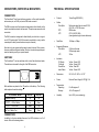
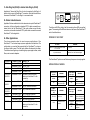
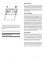
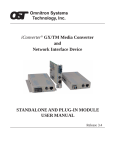
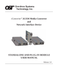
________________________________________________________________________
OmniHawk™ 4/16 Token Ring
Fiber Converter
User’s Manual
___________________________________________________
27 Mauchly, Suite #201, Irvine, CA 92618
( 714) 250-6510
Document # 040-00039-001
SAFETY CONSIDERATIONS
NOTES
WARNING
The instructions in this User Manual are for use by qualified personnel only. To avoid electrical shock, do not
perform any servicing of this unit or the power supply module, other than that contained in the operating
instructions, unless you are qualified and certified to do so by OST.
____________________________________________________________________________________________________________________
__________________________________________________________
CAUTION
__________________________________________________________
All user required operations may be performed without ever opening the unit. Never attempt to open or
remove the cover or tamper with the power supply module.
__________________________________________________________
LINE VOLTAGE
Before connecting the power units to the line voltage, make sure that the voltage of the power source (wall
outlet) matches the voltage specified on the power units.
__________________________________________________________
__________________________________________________________
WARRANTY
This OST product is warranted to the original purchaser against defects in material and workmanship for a
period of TWO YEARS from the date of shipment. A LIFETME warranty may be obtained by the original
purchaser by REGISTERING this product with OST within 90 days from the date of shipment. TO REGISTER, PLEASE COMPLETE AND MAIL OR FAX THE REGISTRATION CARD. During the warranty period,
OST will, at its option, repair or replace products which prove to be defective.
For warranty service, the product must be sent to an OST designated repair facility, at Buyer’s expense.
OST will then pay the postage/shipping charges to return the product to Buyer (using OST’s standard shipping method).
LIMITATIONS OF WARRANTY
The foregoing warranty shall not apply to defects resulting from improper or inadequate use and/or maintenance of the equipment by Buyer, Buyer-supplied equipment, Buyer-supplied interfacing, unauthorized
modifications or tampering with equipment (including removal of equipment cover by personnel not specifically authorized and certified by OST), or misuse, or operation outside the environmental specification of the
product (including but not limited to voltage, ambient temperature, radiation, unusual dust, etc.), or improper
site preparation or maintenance.
__________________________________________________________
__________________________________________________________
__________________________________________________________
__________________________________________________________
__________________________________________________________
__________________________________________________________
__________________________________________________________
No other warranty is expressed or implied, OST specifically disclaims the implied warranties of merchantability and fitness for any particular purpose.
__________________________________________________________
EXCLUSIVE REMEDIES
__________________________________________________________
The remedies provided herein are the Buyer’s sole and exclusive remedies. OST shall not be liable for any
direct, indirect, special, incidental, or consequential damages, whether based on contract, tort, or any legal
theory.
__________________________________________________________
FCC WARNING
__________________________________________________________
This equipment has been tested and found to comply with the limits for a class A digital device, pursuant to
part 15 of the FCC rules. These limits are designed to provide a reasonable protection against harmful
interference when the equipment is operated in a commercial environment. The equipment generates, uses,
and can radiate radio frequency energy and, if not installed and used in accordance with the instruction
manual, may cause harmful interference to radio communications. Operation of this equipment in a residential area is likely to cause harmful interference in which case the user will be required to correct the interference at his own expense. Any changes or modifications not expressly approved by the manufacturer could
void the user authority to operate the equipment.
__________________________________________________________
__________________________________________________________
TECHNICAL SUPPORT
If you encounter any problems in installing or maintaining this equipment,
do not hesitate to call, fax or write Omnitron’s technical support:
Omnitron Systems Technology, Inc.
27 Mauchly, Suite 201
Irvine, CA 92618
Phone: 714-250-6510
Fax:
714-250-6514
OmniHawk™ 4/16 Token Ring
Fiber Converter
USER’S MANUAL
GENERAL DESCRIPTION
The OmniHawk™ 4/16 Token Ring fiber converter provides a solution to
heterogeneous Token Ring media environments. Conversions between
copper (CAT-5 or Type 1) and fiber optic interfaces are required in most
modern Token Ring installations.
Fiber optic cabling is the media of choice for connecting separate buildings
within a campus network. Even trunk connections between floors of a single
building benefit from the advantages of fiber optic media. In heavy industrial
settings, fiber optic media may provide the only reliable connectivity even
when the distances traveled are short. Moreover, a growing number of workstation interface cards now feature fiber optic connection.
The OmniHawk™ is packaged for a wide variety of media conversion applications. It can be wall mounted, rack mounted, or attached directly to the
DB9 connector of a workstation.
ALWAYS CONNECT
The OmniHawk™ is specifically designed with an intelligent connection algorithm which assures dependable communications. Whether it is attached
to passive or active devices, the OmniHawk™ will always make a good
connection. The fiber optic interface adheres to the IEEE 802.5j specification for fiber optic attachment.
12
1
CONNECTORS, SWITCHES & INDICATORS
CONNECTORS
The OmniHawk™ has three interface connectors: a fiber optic transmitter
and receiver pair, an RJ45 jack, and a DB9 male connector.
TECHNICAL SPECIFICATIONS
•
Protocol:
•
Cables
Fiber Optic:
The DB9 connector and the chassis are designed to attach directly to the
rear of a workstation network interface card. The jack screws ensure a solid
connection.
The RJ45 connector is designed to attach directly to a hub lobe or ring out
via a CAT-5 patch cable. The RJ45 connector may attach to a ring in with a
crossed patch cable (transmit and receive pairs crossed).
Note that only one copper interface may be used at a time. Other connections are possible with special cables. Omnitron’s technical support department can assist you with your special needs.
SWITCHES
STP:
UTP:
ATTACHMENT MODE
SWITCH 1
SWITCH 2
Automatic Sensing
Up
Up
UTP/STP --> RO or Station
Up
Down
UTP/STP --> RI or Lobe
Down
Up
Self Test / Media Test
Down
Down
Multi-mode glass fiber of sizes 50/125,
62.5/125, or 100/140 micron
DB9 female
CAT-5 (EIA/TIA 568):
(lower grade wiring at shorter distances)
•
Data Rate:
•
Supported Distances
Fiber Optic:
2.5 Km multi-mode
20 Km single-mode
UTP:
300 m
•
Indicators
FO Ready
Cu Ready
Power/Error
Insert Status
Yellow - Green LED
Yellow - Green LED
Yellow - Red LED
Yellow - Green LED
•
Dimensions:
W: 3.46” x D: 2.83” x H: 0.78”
•
Power:
External Power Supply 9 VDC @ 1.2A
•
Temperature
Operating:
Storage:
0 to 45 degrees C
-40 to 75 degrees C
Humidity:
Up to 90% (non condensing)
The OmniHawk™ has two switches which control the attachment mode.
The switches are located to the right of the DB9 connector.
Both switches are placed in the UP position at the factory. The following
table explains the switch settings.
Token Ring (IEEE 802.5)
•
16 Mbps or 4 Mbps
CONNECTORS
In addition to the two switches there are four LED indicators in a 2 x 2
cluster. Refer to the drawing below.
2
11
C. Hub Ring Out (RJ45) to distant hub Ring In (RJ45)
Application C shows the Ring Out of one hub connected to the Ring In of
another hub via a pair of OmniHawk™ converters. Note that the cable from
the second OmniHawk™ to the Ring In is a crossed cable.
D. Distant Lobe Extension
Application D shows a distant hub in lobe extension via a pair of OmniHawk™
converters. In this configuration a standard CAT-5 cable connects the extended hub to the first OmniHawk™, fiber optic cables connect the two
converters, and another standard CAT-5 patch cable connects the second
OmniHawk™ to the target hub.
The bottom left LED is yellow / red, the remaining three LEDs are yellow /
green. The meaning of the LEDs are shown on the cover of the OmniHawk™
and in the tables below.
POWER UP LED TEST
E. Other Applications
The above examples show the most common applications of the
OmniHawk™. Your network may require an application not listed here. The
configuration you need will be supported by the OmniHawk™ as long as
the correct cable is used. The fiber optic cables will always be the same.
The table below will guide you in selecting the proper copper cables, media
filters, and connector adapters.
ALL LEDS
MEANING
Yellow for 1/2 second then Green or Red
or 1/2 second
Any other behavior
Self Test OK
Failed Self Test, Call Technical Support
The OmniHawk™ performs a self test every time power is newly applied.
OST PART #
9300-P45
9301-P45X
5700-CMF &
9301-P45X
5701-IP45 &
9300-P45
5701-IP45 &
9301-P45X
9310-IF9
9311-IF9X
9320-FM9
CONNECT FROM
OmniHawk™ RJ45
OmniHawk™ RJ45
OmniHawk™ RJ45
OmniHawk™ RJ45
OmniHawk™ RJ45
CONNECT TO
Lobe, RJ45
Ring Out, RJ45
Ring In, RJ45
Workstation, RJ45
Workstation, DB9(if not directly
attaching the OmniHawk™ to the
workstation)
OmniHawk™ RJ45
Lobe, IBM Data Connector
OmniHawk™ RJ45
OmniHawk™ RJ45
Ring Out, IBM Data Connector
Ring In, IBM Data Connector
OmniHawk™ DB9
OmniHawk™ DB9
OmniHawk™ DB9
OmniHawk™ DB9
Ring In, IBM Data Connector
Ring Out, IBM Data Connector
Lobe, IBM Data Connector
Workstation, DB9(if not directly
attaching the OmniHawk™ to the
workstation)
10
OPERATIONAL MODES
FIBER READY
(top left)
COPPER READY
(top right)
MEANING
GREEN
Data received from
fiber
GREEN
Off
No data is being
received from Fiber
OFF
POWER /
ERROR (bot.
left)
YELLOW
RED
MEANING
Power is on
An attachment error
occurred
Data received from
copper
No data is being
received from copper
INSERT STATUS
(bot. right)
MEANING
GREEN
The fiber optic and
copper interfaces have
both actively inserted
FLASHING
GREEN
OFF
3
MEANING
Still attempting to
insert
Insertion is not being
attempted
The operational modes are:
APPLICATIONS
The following drawing illustrates three different applications of the
OmniHawk™.
1. AUTOMATIC SENSING
2. UTP/STP —> RO or STATION
3. UTP/STP —> RI or LOBE
The power / error LED turns red when an attachment error occurs. An error
can only occur when attaching to active devices (devices which signal for
insertion with phantom current or the fiber optic key). The error condition
occurs when copper device initiates the phantom current and the fiber optic
device initiates the fiber optic key. In Token Ring, the active insertion process may only be directed from one direction.
SELF TEST / MEDIA TEST MODE
FIBER READY
(top left)
COPPER
READY (top
right)
MEANING
MEANING
GREEN
Data received from
fiber
GREEN
OFF
No data is being
received from fiber
OFF
No data is being
received from copper
INSERT
STATUS (bot.
right)
MEANING
POWER /
ERROR (bot.
left)
YELLOW
MEANING
Power is on
YELLOW
Data received from
copper
The OmniHawk™ is
in the self test /
media test mode.
DIAGNOSTIC FEATURES
The OmniHawk™ diagnostic features make it easy to install and maintain.
There are four levels of diagnostics: Power-On LED Test, Self Test / Media
Test, Installation Test, and run-time ready and error monitoring.
A. STP Workstation (DB9) to distant hub (RJ45)
Application A shows an STP workstation connecting via its DB9 connector
directly to one OmniHawk™, which is connected to a second OmniHawk™
via fiber optic cables. The last connection to the hub is made via a standard
CAT-5 patch cable.
B. Fiber optic Workstation to hub (RJ45)
Application B shows a fiber optic workstation connecting to an OmniHawk™
vi its fiber optic cables. The OmniHawk™ connects to the hub via a standard CAT-5 patch cable.
4
9
POWER-ON LED TEST
Every time power is newly applied to the OmniHawk™ the LEDs will flash
through all possible colors to give the user the assurance that other diagnostic information may be correctly interpreted. The LEDs will flash all yellow, then either green or red. After that, the LED test is over and the LEDs
will illuminate according to the mode (as set by the switches) and the current media connections.
SELF TEST / MEDIA TEST
To test the integrity of copper patch cables and any intervening baluns connect the OmniHawk™ to an unused lobe of any powered hub. If the cable is
unbroken, the copper ready LED will light green. If the cable is broken, the
LED will be off.
The self test / media test ensures that the OmniHawk™ is fully operational.
Testing occurs when the switches both set to the DOWN position. The bottom two LEDs will both illuminate yellow indicating that power is on and that
the unit is in the test mode. The testing checks both the data passing capability of the OmniHawk™ and the physical continuity of the media. For both
fiber optic and copper media test data is looped back to the OmniHawk™.
When a looped back fiber cable is connected from the transmit (TX) to the
receive (RX) fiber optic connectors, the fiber optic ready LED lights green.
When a CAT-5 patch cable is connected from the OmniHawk™ to an unused lobe of a hub, the copper ready LED lights green. If good connections
are made and the corresponding LED does not illuminate, then the media is
broken. This CAT-5 cable used in this test may be inserted into an operating hub since the OmniHawk™ will not assert phantom current during the
test mode (and consequently will not enter the network).
Note that the power / error LED and the test mode LED will both be yellow.
INSTALLATION TEST
NOTE: TURN OFF THE SELF TEST / MEDIA TEST MODE TO RETURN
TO NORMAL OPERATIONAL MODES.
The OmniHawk™ tests for proper installation and lights the power / error
LED red if a wrong connection is made. This check will only be made when
the connecting devices are stations and/or active hubs. Among active devices, there are initiators and echoers. An initiator is a device that either
sends phantom current or the fiber optic insertion key. An echoer is a device that receives phantom current or the fiber optic insertion key.
The OmniHawk™ installation test feature warns the installer that an initiator
has been connected to both the fiber optic interface and to the copper interface. Since it doesn’t make sense to connect two ring out (RO) trunk lines
together, the power / error LED warns of this condition by lighting red.
8
5
RUN-TIME ACTIVITY & ERROR MONITORING
SITE REQUIREMENTS
During normal operation the fiber optic and copper ready LEDs provide
continuous diagnostic information. These LEDs detect and display token
ring activity.
A power outlet should be available within 5 ft. of the unit. The following
power supply modules are required for the following power outlets:
The insert status LED informs the user of the insert status of the fiber optic
and copper media. This LED lights green when both the active signaling
fiber optic and copper devices have successfully reached insertion.
The insert status LED flashes when the OmniHawk™ has received phantom current on its copper side but has not yet achieved insertion on its fiber
optic side, or conversely, when the unit has received the fiber optic key on
its fiber side but has not yet sensed a phantom current echoer on its copper
side.
When the OmniHawk™ connects to passive devices, the insert status LED
will always be off.
UNPACKING
a. Visual Inspection - before unpacking, a visual inspection should be conducted in order to detect any physical damage to the equipment. Any
evidence of damage should be noted and reported immediately.
b. Unpacking - place shipping container on a flat surface, cut straps or
tape, open top. Take out each item carefully and place securely on a
clean flat surface. Return all packing material into container (foam, boxes
etc.), close and store away for future re-use.
c.
Inspection - Inspect each item for any apparent damage, any evidence
of damage should be noted and reported immediately.
MODEL
POWER OUTLET
3900
110 Volt - 60 Hz
3900-2
220 Volt - 50 Hz
3910
110 Volt - 60 Hz
3910-2
220 Volt - 50 Hz
NORMAL CONFIGURATION
a. Attach the workstation or hub with the appropriate cable to the
OmniHawk™.
b. Plug the external power supply into the appropriate AC wall outlet.
c. Plug the power jack into the OmniHawk™ power connector.
f. The LEDs will flash during their self test, then settle according to the
current connection status.
Refer to the APPLICATIONS section for useful application information.
ALTERNATE POWER SOURCE
Some Token Ring network interface cards supply power via the DB-9 connector. Compatible network interface cards supply +5V on pin 3 and ground
on pins 2, 4, 7, and 8. When power from the network interface card is available, the OmniHawk™ will use that power and the external power supply
may be disconnected.
d. Content - Review the content; the following items should be included:
•
•
•
OmniHawk™ module (1)
power supply module
User’s Manual (the document you are now reading)
Please note any missing items or discrepancies and report them immediately.
6
INSTALLATION TEST CONFIGURATIONS
The OmniHawk™ supports the following media test configuration.
Loopback Media Test
To test the integrity of fiber optic media connect the fiber optic patch cable
in a loopback fashion (i.e., one end in the transmit port and the other in the
receive port). If the fiber is unbroken, the OmniHawk™ fiber ready LED will
illuminate green. If the fiber is partially or completely broken, the LED will be
off.
7