1
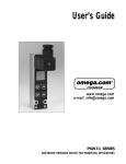
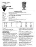
VA Series
Vapor Actuated Dial Thermometer
INSTRUCTION
SHEET
M1982/0902
General Description
The OMEGA® VA Series Vapor Actuated Thermometer is ideal for remote
readings, such as panel installations, with capillary lengths from 5 to 100
feet. This thermometer gives excellent readings above and below ambient
temperature and, being vapor actuated, is not subject to reading errors due
to either RFI/EMI interference or ambient temperature variations along the
capillary tube length.
Available Models
Front Flange
(Panel Mount)
U-Clamp (Panel Mount)
Figure 1. Case Style
Rear Flange
(Surface Mounted)
Installing the Vapor Actuated Thermometer
Unpacking Instructions
Remove the Packing List and verify that you have received all equipment,
including the following (quantities in parentheses):
Vapor Actuated Dial Thermometer (1)
Operator’s Manual (1)
If you have any questions about the shipment, please call the OMEGA
Customer Service Department.
When you receive the shipment, inspect the container and equipment for
signs of damage. Note any evidence of rough handling in transit.
Immediately report any damage to the shipping agent.
VA Series Vapor Actuated Dial Thermometer
NOTE
The carrier will not honor damage claims unless all shipping
material is saved for inspection. After examining and
removing contents, save packing material and carton in the
event reshipment is necessary.
Case and Mounting Dimensions
Front Flange
(Panel Mount)
U-Clamp
(Panel Mount)
Rear Flange
(Surface Mount)
Figure 2. Case and Mounting Dimensions
Installing the Indicating Head
Surface Mount (Rear Flange)
1. Make a circular cutout in the center of the hole mounting pattern for
the capillary tube to fit through.
2. Drill the three (3) mounting holes.
3. Using the screw holes that you drilled, screw the back of the head to
your wall or panel.
2
VA Series Vapor Actuated Dial Thermometer
Flush Mount (Front Flange and U-Clamp)
1. Make a circular cutout in the panel slightly larger than the case.
2. Drill three (3) mounting holes for the Front Flange Model.
3. From the front of the panel, pass the bulb and capillary through the
cutout.
4. Affix the head to the panel:
4a. U-clamp Model: Tighten U-clamp(s) against the back of your
panel.
4b. Front Flange Model: Screw the flange to the front of your panel,
using the screw holes that you drilled.
Installing the Bulb
NOTE
If the bulb is installed more than 10 feet above or below the
dial, it may be necessary to recalibrate the instrument.
3
VA Series Vapor Actuated Dial Thermometer
Standard Bulb Dimensions (inches)
Immerse the thermometer stem at least A inches (or entire stem,
whichever is less) in the medium being measured, for best reading.
Union Connections
CAUTION
Tighten the thermometer to its fitting using a wrench
applied to the hex or flats above the threads. Never tighten
by hand.
1. Unscrew and remove the 1⁄2" NPT fitting, using a 7⁄8" wrench.
2. Screw the 1⁄2" NPT fitting into the threaded process opening.
3. Insert the bulb through the 1⁄2" NPT fitting. Tighten it in place by
screwing the jam nut into the top of the 1⁄2" NPT fitting with an 11⁄16"
wrench.
4
VA Series Vapor Actuated Dial Thermometer
NOTE
Use a thermowell in all pressurized applications. Be sure
case temperature does not exceed 200°F (93°C).
Thermowells
1. Remove the thermowell and screw it into the process so that no
leaking occurs. Use thread sealant as required.
2. Place the bulb in the thermowell. Tighten the bulb in place by
screwing the jam nut into the top of the 1⁄2" fitting with an 11⁄16" wrench.
Bendable Extensions
I . Place the bulb in the thermowell, or directly in the process.
NOTE
Use a thermowell whenever the bulb would be exposed to
pressure, fluid velocity, or corrosive media.
2. Slide the compression fitting down and screw the 1⁄2" NPT fitting into
the process (or thermowell) threads.
3. Tighten the top hex of the sliding union until the bendable extension
does not slide in or out.
4. Gently bend the remaining portion of the extension out of the way.
Operation
Recommended operating temperature is in the upper 2⁄3 of the dial scale.
5
VA Series Vapor Actuated Dial Thermometer
Vapor actuated thermometers give excellent readings when the bulb
temperature is either above or below the temperature of the indicating
head. Avoid applications in which the bulb and head are the same
temperature (ambient applications). If the bulb “crosses ambient” (i.e.,
goes from hotter than the indicating head to cooler or vice versa), some
pointer fluctuations will occur for up to two minutes during this
transition.
Recalibration
The VA Series vapor actuated thermometers are manufactured with
threaded, press fit and snap-ring lenses which can be easily removed
for field calibration.
To recalibrate your vapor actuated thermometer:
1. Remove the thermometer from its fitting.
2. Remove the lens.
4. Immerse the bulb totally in an agitated liquid for at least 3 minutes
with a master reference thermometer, until they reach equilibrium.
5. Use a wrench, coin or screwdriver to turn the slotted hex nut on the
back of the thermometer case until the pointer is at the proper
reading on the scale.
6. Replace the lens and reinstall the thermometer in its fitting.
Care of the Vapor Actuated Thermometer
• Avoid bending the stem, as this will result in frictional errors in
indication.
• Do not kink or flatten the capillary tube.
• Dampen any capillary vibration, as this may cause capillary breakage
over time.
6
VA Series Vapor Actuated Dial Thermometer
Specifications
Dial Sixes:
Dial:
Pointer:
Movement:
Bourdon Tube:
Accuracy:
Case:
Process
Connection:
Window:
Bulb:
Capillary:
Ranges:
Applications:
2", 2 1⁄2", 3 1⁄2", 4 1⁄2"
Aluminum with white finish and black markings
Furnished standard adjustable
Brass with precision gearing
Phosphor bronze
Plus or minus one scale division
Stainless steel on all front flange and U-clamp models.
Back flange models in stainless (2"), black steel (3 1⁄2")
or Valox (4 1⁄2")
Plain bulb, 1⁄2" NPT Union, 1⁄2" NPT sliding union
on 12 Connection: bendable extension, or thermowell.
Polycarbonate. Glass in 3 1⁄2" and 4 1⁄2" back flange
models
Stainless steel or nickel plated copper. Bulb O.D. 7⁄16"
(optional 1⁄4" O.D. x 2" length on -40 to 65°F range
only). Bulb lengths vary from 2" to 6" depending on
capillary length
Nickel plated copper, copper with bronze braid
armor, stainless steel, stainless steel with stainless
steel armor. Capillary lengths 1 to 100 feet (standard
length 5 feet)
Over twenty °F and °F/°C ranges available, from -40°
to +450°F
Control panels, chemical processing, pipelines, food
processing, OEM applications, ovens, solar heating,
Vapor actuated thermometers give excellent readings when
the bulb temperature is either above or below the
temperature of the indicating head. Avoid applications in
which the bulb and head are the same temperature
(ambient applications). If the bulb “crosses ambient” (i.e.,
goes from hotter than the indicating
7
Servicing Europe:
OMEGAnet ® Online Service
www.omega.com
ISO 9001 Certified
Canada:
Postbus 8034, 1180 LA Amstelveen, The Netherlands
Tel: +31 (0)20 3472121
FAX: +31 (0)20 6434643
Toll Free in Benelux: 0800 0993344
e-mail: [email protected]
Czech
Republic:
Rudé armády 1868, 733 01 Karviná 8
Tel: +420 (0)69 6311899
FAX: +420 (0)69 6311114
Toll Free: 0800-1-66342
e-mail: [email protected]
France:
11, rue Jacques Cartier, 78280 Guyancourt, France
Tel: +33 (0)1 61 37 29 00
FAX: +33 (0)1 30 57 54 27
Toll Free in France: 0800 466 342
e-mail: [email protected]
Germany/
Austria:
Daimlerstrasse 26, D-75392 Deckenpfronn, Germany
Tel: +49 (0)7056 9398-0
FAX: +49 (0)7056 9398-29
Toll Free in Germany: 0800 639 7678
e-mail: [email protected]
United
Kingdom:
One Omega Drive, River Bend Technology Centre
Northbank, Irlam, Manchester
Internet e-mail
[email protected]
Servicing North America:
USA:
Benelux:
One Omega Drive, Box 4047
Stamford CT 06907-0047
Tel: (203) 359-1660
e-mail: [email protected]
FAX: (203) 359-7700
976 Bergar
Laval (Quebec) H7L 5A1
Tel: (514) 856-6928
e-mail: [email protected]
FAX: (514) 856-6886
For immediate technical or application assistance:
USA and
Canada:
Sales Service: 1-800-826-6342 / 1-800-TC-OMEGA®
Customer Service: 1-800-622-2378 / 1-800-622-BEST®
Engineering Service: 1-800-872-9436 / 1-800-USA-WHEN®
TELEX: 996404 EASYLINK: 62968934 CABLE: OMEGA
Mexico:
En Español: (001) 203-359-7803
FAX: (001) 203-359-7807
e-mail:[email protected]
[email protected]
ISO 9002 Certified M44 5BD United Kingdom
Tel: +44 (0)161 777 6611
FAX: +44 (0)161 777 6622
Toll Free in United Kingdom: 0800-488-488
e-mail: [email protected]
It is the policy of OMEGA to comply with all worldwide safety and EMC/EMI regulations that apply. OMEGA is constantly pursuing certification of its
products to the European New Approach Directives. OMEGA will add the CE mark to every appropriate device upon certification.
The information contained in this document is believed to be correct, but OMEGA Engineering, Inc. accepts no liability for any errors it contains, and reserves the right to alter
specifications without notice.
WARNING: These products are not designed for use in, and should not be used for, patient-connected applications.
WARRANTY/DISCLAIMER
OMEGA ENGINEERING, INC. warrants this unit to be free of defects in materials and workmanship for a period of 13 months from
date of purchase. OMEGA’s WARRANTY adds an additional one (1) month grace period to the normal one (1) year product
warranty to cover handling and shipping time. This ensures that OMEGA’s customers receive maximum coverage on each
product.
If the unit malfunctions, it must be returned to the factory for evaluation. OMEGA’s Customer Service Department will issue an
Authorized Return (AR) number immediately upon phone or written request. Upon examination by OMEGA, if the unit is found to be
defective, it will be repaired or replaced at no charge. OMEGA’s WARRANTY does not apply to defects resulting from any action of the
purchaser, including but not limited to mishandling, improper interfacing, operation outside of design limits, improper repair, or
unauthorized modification. This WARRANTY is VOID if the unit shows evidence of having been tampered with or shows evidence of
having been damaged as a result of excessive corrosion; or current, heat, moisture or vibration; improper specification;
misapplication; misuse or other operating conditions outside of OMEGA’s control. Components which wear are not warranted,
including but not limited to contact points, fuses, and triacs.
OMEGA is pleased to offer suggestions on the use of its various products. However, OMEGA neither assumes responsibility
for any omissions or errors nor assumes liability for any damages that result from the use of its products in accordance with
information provided by OMEGA, either verbal or written. OMEGA warrants only that the parts manufactured by it will be as
specified and free of defects. OMEGA MAKES NO OTHER WARRANTIES OR REPRESENTATIONS OF ANY KIND
WHATSOEVER, EXPRESS OR IMPLIED, EXCEPT THAT OF TITLE, AND ALL IMPLIED WARRANTIES INCLUDING ANY
WARRANTY OF MERCHANTABILITY AND FITNESS FOR A PARTICULAR PURPOSE ARE HEREBY DISCLAIMED. LIMITATION
OF LIABILITY: The remedies of purchaser set forth herein are exclusive, and the total liability of OMEGA with respect to this
order, whether based on contract, warranty, negligence, indemnification, strict liability or otherwise, shall not exceed the
purchase price of the component upon which liability is based. In no event shall OMEGA be liable for consequential,
incidental or special damages.
CONDITIONS: Equipment sold by OMEGA is not intended to be used, nor shall it be used: (1) as a “Basic Component” under 10 CFR
21 (NRC), used in or with any nuclear installation or activity; or (2) in medical applications or used on humans. Should any Product(s)
be used in or with any nuclear installation or activity, medical application, used on humans, or misused in any way, OMEGA assumes
no responsibility as set forth in our basic WARRANTY/DISCLAIMER language, and, additionally, purchaser will indemnify OMEGA and
hold OMEGA harmless from any liability or damage whatsoever arising out of the use of the Product(s) in such a manner.
RETURN REQUESTS / INQUIRIES
Direct all warranty and repair requests/inquiries to the OMEGA Customer Service Department. BEFORE RETURNING ANY
PRODUCT(S) TO OMEGA, PURCHASER MUST OBTAIN AN AUTHORIZED RETURN (AR) NUMBER FROM OMEGA’S CUSTOMER
SERVICE DEPARTMENT (IN ORDER TO AVOID PROCESSING DELAYS). The assigned AR number should then be marked on the
outside of the return package and on any correspondence.
The purchaser is responsible for shipping charges, freight, insurance and proper packaging to prevent breakage in transit.
FOR WARRANTY RETURNS, please have the following information available BEFORE contacting OMEGA:
1. Purchase Order number under which the product was
PURCHASED,
2. Model and serial number of the product under warranty, and
3. Repair instructions and/or specific problems relative to the
product.
FOR NON-WARRANTY REPAIRS, consult OMEGA for current repair charges. Have the following information available BEFORE contacting OMEGA:
1. Purchase Order number to cover the COST of the repair,
2. Model and serial number of the product, and
3. Repair instructions and/or specific problems relative to
the product.
OMEGA’s policy is to make running changes, not model changes, whenever an improvement is possible. This affords our customers the latest in
technology and engineering.
OMEGA is a registered trademark of OMEGA ENGINEERING, INC.
© Copyright 2002 OMEGA ENGINEERING, INC. All rights reserved. This document may not be copied, photocopied, reproduced, translated, or
reduced to any electronic medium or machine-readable form, in whole or in part, without the prior written consent of OMEGA ENGINEERING,
INC.
M1982/0901