1
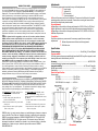
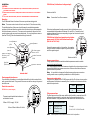
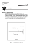
User’s Guide
PX548
Wet/Wet Differential
Pressure Sensor
www.omega.com
e-mail: [email protected]
OMEGAnet®On-Line Service
www.omega.com
Internet e-mail
[email protected]
Servicing North America:
USA:
ISO 9001 Certified
Canada:
One Omega Drive, P.O. Box 4047
Stamford CT 06907-0047
TEL: (203) 359-1660
e-mail: [email protected]
976 Bergar
Laval (Quebec) H7L 5A1
TEL: (514) 856-6928
e-mail: [email protected]
FAX: (203) 359-7700
FAX: (514) 856-6886
For immediate technical or application assistance:
USA and Canada:
Mexico:
Sales Service: 1-800-826-6342 / 1-800-TC-OMEGA®
Customer Service: 1-800-622-2378 / 1-800-622-BEST®
Engineering Service: 1-800-872-9436 / 1-800-USA-WHEN®
TELEX: 996404 EASYLINK: 62968934 CABLE: OMEGA
TEL: (001) 800-826-6342 FAX: (001) 203-359-7807
En Espan˜ol: (001) 203-359-7803
e-mail: [email protected]
[email protected]
Servicing Europe:
Benelux:
TEL:
Czech Republic:
France:
Germany/Austria:
United Kingdom:
ISO 9002 Certified
Postbus 8034, 1180 LA Amstelveen, The Netherlands
+31 (0)20 6418405
FAX: +31 (0)20 6434643
Toll Free in Benelux: 0800 0993344
e-mail: [email protected]
Rudé armády 1868, 733 01 Karviná 8
TEL: +420 (0)69 6311899
FAX: +420 (0)69 6311114
Toll Free in Czech Republic: 0800-1-66342
e-mail:[email protected]
9, rue Denis Papin, 78190 Trappes
TEL: +33 (0)130 621 400
FAX: +33 (0)130 699 120
Toll Free in France: 0800-4-06342
e-mail: [email protected]
Daimlerstrasse 26, D-75392 Deckenpfronn, Germany
TEL: +49 (0)7056 3017
FAX: +49 (0)7056 8540
Toll Free in Germany: 0800 TC-OMEGASM
e-mail: [email protected]
One Omega Drive, River Bend Technology Centre
Northbank, Irlam, Manchester
M44 5EX United Kingdom
TEL: +44 (0)161 777 6611
FAX: +44 (0)161 777 6622
Toll Free in United Kingdom: 0800 488 488
e-mail: [email protected]
It is the policy of OMEGA to comply with all worldwide safety and EMC/EMI regulations
that apply. OMEGA is constantly pursuing certification of its products to the European
New Approach Directives. OMEGA will add the CE mark to every appropriate device upon
certification. The information contained in this document is believed to be correct, but
OMEGA Engineering, Inc. accepts no liability for any errors it contains, and reserves the
right to alter specifications without notice.
WARNING: These products are not designed for use in, and should not be used for,
patient-connected applications.
Where Do I Find Everything I Need for
Process Measurement and Control?
OMEGA…Of Course!
TEMPERATURE
e Thermocouple, RTD & Thermistor Probes, Connectors, Panels & Assemblies
e Wire: Thermocouple, RTD & Thermistor
e Calibrators & Ice Point References
e Recorders, Controllers & Process Monitors
e Infrared Pyrometers
PRESSURE, STRAIN AND FORCE
e Transducers & Strain Gages
e Load Cells & Pressure Gages
e Displacement Transducers
e Instrumentation & Accessories
FLOW/LEVEL
e Rotameters, Gas Mass Flowmeters & Flow Computers
e Air Velocity Indicators
e Turbine/Paddlewheel Systems
e Totalizers & Batch Controllers
pH/CONDUCTIVITY
e pH Electrodes, Testers & Accessories
e Benchtop/Laboratory Meters
e Controllers, Calibrators, Simulators & Pumps
e Industrial pH & Conductivity Equipment
DATA ACQUISITION
e Data Acquisition & Engineering Software
e Communications-Based Acquisition Systems
e Plug-in Cards for Apple, IBM & Compatibles
e Datalogging Systems
e Recorders, Printers & Plotters
HEATERS
e Heating Cable
e Cartridge & Strip Heaters
e Immersion & Band Heaters
e Flexible Heaters
e Laboratory Heaters
ENVIRONMENTAL
MONITORING AND CONTROL
e Metering & Control Instrumentation
e Refractometers
e Pumps & Tubing
e Air, Soil & Water Monitors
e Industrial Water & Wastewater Treatment
e pH, Conductivity & Dissolved Oxygen Instruments
M-3295/0300
WARRANTY/DISCLAIMER
OMEGA ENGINEERING, INC. warrants this unit to be free of defects in materials and workmanship
for a period of 13 months from date of purchase. OMEGA’s WARRANTY adds an additional one
(1) month grace period to the normal one (1) year product warranty to cover handling and
shipping time. This ensures that OMEGA’s customers receive maximum coverage on each product.
If the unit malfunctions, it must be returned to the factory for evaluation. OMEGA’s Customer
Service Department will issue an Authorized Return (AR) number immediately upon phone or
written request. Upon examination by OMEGA, if the unit is found to be defective, it will be repaired
or replaced at no charge. OMEGA’s WARRANTY does not apply to defects resulting from any
action of the purchaser, including but not limited to mishandling, improper interfacing, operation
outside of design limits, improper repair, or unauthorized modification. This WARRANTY is VOID if
the unit shows evidence of having been tampered with or shows evidence of having been
damaged as a result of excessive corrosion; or current, heat, moisture or vibration; improper
specification; misapplication; misuse or other operating conditions outside of OMEGA’s control.
Components which wear are not warranted, including but not limited to contact points, fuses, and
triacs.
OMEGA is pleased to offer suggestions on the use of its various products. However,
OMEGA neither assumes responsibility for any omissions or errors nor assumes
liability for any damages that result from the use of its products in accordance with
information provided by OMEGA, either verbal or written. OMEGA warrants only that the
parts manufactured by it will be as specified and free of defects. OMEGA MAKES NO
OTHER WARRANTIES OR REPRESENTATIONS OF ANY KIND WHATSOEVER, EXPRESS OR
IMPLIED, EXCEPT THAT OF TITLE, AND ALL IMPLIED WARRANTIES INCLUDING ANY WARRANTY OF MERCHANTABILITY AND FITNESS FOR A PARTICULAR PURPOSE ARE HEREBY
DISCLAIMED. LIMITATION OF LIABILITY: The remedies of purchaser set forth herein are
exclusive, and the total liability of OMEGA with respect to this order, whether based on
contract, warranty, negligence, indemnification, strict liability or otherwise, shall not
exceed the purchase price of the component upon which liability is based. In no event
shall OMEGA be liable for consequential, incidental or special damages.
CONDITIONS: Equipment sold by OMEGA is not intended to be used, nor shall it be used: (1) as a
“Basic Component” under 10 CFR 21 (NRC), used in or with any nuclear installation or activity; or
(2) in medical applications or used on humans. Should any Product(s) be used in or with any
nuclear installation or activity, medical application, used on humans, or misused in any way, OMEGA
assumes no responsibility as set forth in our basic WARRANTY / DISCLAIMER language, and,
additionally, purchaser will indemnify OMEGA and hold OMEGA harmless from any liability or
damage whatsoever arising out of the use of the Product(s) in such a manner.
RETURN REQUESTS/INQUIRIES
Direct all warranty and repair requests/inquiries to the OMEGA Customer Service Department.
BEFORE RETURNING ANY PRODUCT(S) TO OMEGA, PURCHASER MUST OBTAIN AN AUTHORIZED
RETURN (AR) NUMBER FROM OMEGA’S CUSTOMER SERVICE DEPARTMENT (IN ORDER TO AVOID
PROCESSING DELAYS). The assigned AR number should then be marked on the outside of the
return package and on any correspondence. The purchaser is responsible for shipping charges,
freight, insurance and proper packaging to prevent breakage in transit.
FOR WARRANTY RETURNS, please have the
following information available BEFORE
contacting OMEGA:
1. Purchase Order number under which the
product was PURCHASED,
2. Model and serial number of the product under
warranty, and
3. Repair instructions and/or specific problems
relative to the product.
FOR NON-WARRANTY REPAIRS, consult
OMEGA for current repair charges. Have the
following information available BEFORE contacting OMEGA:
1. Purchase Order number to cover the COST of
the repair,
2. Model and serial number of the product, and
3. Repair instructions and/or specific problems
relative to the product.
OMEGA’s policy is to make running changes, not model changes, whenever an improvement is possible. This affords our customers the latest in technology and engineering.
OMEGA is a registered trademark of OMEGA ENGINEERING, INC. © Copyright 1999
OMEGA ENGINEERING, INC. All rights reserved. This document may not be copied,
photocopied, reproduced, translated, or reduced to any electronic medium or machinereadable form, in whole or in part, without the prior written consent of OMEGA
ENGINEERING, INC.
Adjustments
The following equipment is required to carry out the adjustments:
r Power supply
r Voltmeter or
r Milli-ammeter
r Pressure standard
uConnect the sensor as shown in Installation. The sensor should be put in its normal
operating position (vertical or horizontal). Remove the cover to gain access to the
zero and span adjustment potentiometers.
Zero adjustment
uDepending on the model, set the zero adjustment to: 0.00 V, 4.00 mA or 12.00 mA.
uSpan adjustment is carried out with the required span pressure applied to the +
uDepending on the model, set the span adjustment to: 5.00 V, 10.00 V or 20.00 mA.
uRelease the pressure.
Completion
Check the output at zero pressure and if necessary, repeat the zero and span
adjustments.
r Release the pressure and disconnect the equipment.
r Refit the cover.
Specification
Pressure range:......................................................................0 to ±0.2 inH2O - 0 to ±150 psid
Pressure media:
All fluids, gases and vapors compatible with anodized AU4G, beryllium copper, tin and
brazing solder and Loctite Master Joint 510
Accuracy:............................................................................................................ ±0.25% FS BSL
(including linearity, hysteresis and repeatability)
Long term stability:............................................................................±0.3% over 12 months
Weight (approximate)...........................................................................................................2.1lbs
Dimensions......................................................................................................................see below
Electrical Specification
Power supply
LPX 5000.............................................10 to 30 V d.c.
LPM 5000............................................18 to 30 V d.c.
LPM 5000 (±5 V d.c. output)............±12 V d.c.
G1/8 F via
welded
adapter
Dimensions
Installation
PX548 Series (Unidirectional voltage output)
CAUTION:
1. INCORRECT ELECTRICAL CONNECTIONS CAN, IN CERTAIN CIRCUMSTANCES, DESTROY THE
ELECTRONIC OUTPUT CIRCUIT.
2. BEFORE APPLYING ELECTRICAL POWER, MAKE SURE THE SUPPLY VOLTAGE IS TO THE CORRECT
RATING.
3. THIS A VERY SENSITIVE SENSOR, ONLY APPLY PRESSURE WITHIN THE PRESSURE RANGE.
Mounting
Two M5 threaded holes in the base of the sensor provide mounting points.
Note: The screws must not enter the holes more than 0.4" into the sensor body.
The installed position of the sensor should be away from sudden temperature
variations, shocks and vibrations and should not be close to strong electromagnetic
fields (transformers, motors etc.). The sensor can be mounted in any position, but
mounting at an angle may require zero adjustment. For very low pressure sensors
(less than 2.0 inH2O) the recommended mounting is horizontal.
zero adjustment
(fine)
Minimum load 2 kW
Note:
Connections 5 and 6 are common
If the output cable passes through an area of electrical disturbance, use a
recommended load impedance of between 2 kW and 10 kW . Connect the load
resistance between the wires corresponding to signal and - terminal at a point
furthest from the sensor.
PX548 Series bidirectional operation using bipolar
power supply (±12 Vdc) with bidirectional output
(0±5 Vdc or 0±2.5 Vdc)
span adjustment
zero adjustment
(coarse)
square root output
selection switch
(optional)
filter time response
selector switch
terminal connector
block
gland nut
(cable entry)
pressure connector
Internal detail
Electromagnetic Interference
To avoid electrical interference, use shielded cable with the shield connected to the
earth ground at both ends. The ground of the sensor can be the casing or the ground
terminal screw.
Connect the power supply to + for positive, - for negative,
and 0 for neutral; connect the output to signal for positive
and 0 for negative signal.
Minimum load 1 kW
Pressure connections
The high pressure connector is marked + and the low pressure connector is marked –.
Purging or de-gasing the sensor
Two 5 mm hexagonal socket bleed screws are located on the outer casing and can be
loosened to bleed the two pressure connectors. Make sure that these screws are
tightened after this operation.
Note: It is possible to changeover the bleed screws and pressure connectors
enabling easier access or permitting installation in a difficult position.
Square root output option
This option only applies to the LPX 5000 sensor with 4 to 20 mA two wire connection
and the square root electronics assembly fitted. A switch next to the terminal block
selects the output mode.
Electrical connections
PX548 Series (current output)
The maximum allowable load resistance is
calculated to formula:
R Max = 0.05 (V supply - 10) kW
Where: R Max in kW and V in Volts
Switch
Output mode
OFF
ON
Linear
Square root
Filter response time
The filter response time of the sensor, additional to the built-in response time of 10
milliseconds (approximately), can be set using the three switches next to the
terminal connector. Using combinations of the switches can set different times.
Switch
A
B
C
Note:
Filter response time
200 milliseconds
400 milliseconds
1 second
Example:
Switch A+B = 600 milliseconds
A hollow point is visible when a switch is in the 'on' position.