1
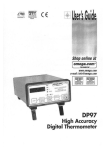
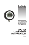
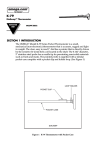
User’s Guide
www.omega.com
e-mail: [email protected]
PSW31 SERIES
ELECTRONIC PRESSURE SWITCH FOR PNEUMATIC APPLICATIONS
OMEGAnet® On-Line Service
www.omega.com
Internet e-mail
[email protected]
Servicing North America:
USA:
ISO 9001 Certified
Canada:
One Omega Drive, P.O. Box 4047
Stamford, CT 06907-0047
TEL: (203) 359-1660
e-mail: [email protected]
976 Bergar
Laval (Quebec) H7L 5A1
TEL: (514) 856-6928
e-mail: [email protected]
FAX: (203) 359-7700
FAX: (514) 856-6886
For immediate technical or application assistance:
USA and Canada:
Sales Service: 1-800-826-6342 / 1-800-TC-OMEGA®
Customer Service: 1-800-622-2378 / 1-800-622-BEST®
Engineering Service: 1-800-872-9436 / 1-800-USA-WHEN®
TELEX: 996404 EASYLINK: 62968934 CABLE: OMEGA
Mexico:
(001) 800-826-6342
En Espanol: (001) 203-359-7803
Benelux:
Postbus 8034, 1180 LA Amstelveen, The Netherlands
TEL: +31 (0)20 6418405
FAX: +31 (0)20 6434643
Toll Free in Benelux: 0800 0993344
e-mail: [email protected]
Czech Republic:
Rudé armády 1868, 733 01 Karviná
TEL: +420 (0)69 6311899
Toll Free in Czech Rep.: 0800-1-66342
FAX: (001) 203-359-7807
e-mail: [email protected]
[email protected]
Servicing Europe:
France:
9, rue Denis Papin, 78190 Trappes
Tel: +33 (0)130 621 400
Toll Free in France: 0800-4-06342
e-mail: [email protected]
FAX: +420 (0)69 6311114
e-mail: [email protected]
FAX: +33 (0)130 699 120
Germany/Austria:
Daimlerstrasse 26, D-75392 Deckenpfronn, Germany
Tel: +49 (0)7056 3017
FAX: +49 (0)7056 8540
Toll Free in Germany: 0800-TC-OMEGA
e-mail: [email protected]
United Kingdom:
ISO 9002 Certified
One Omega Drive, River Bend Technology Centre
Northbank, Irlam, Manchester
M44 5EX, United Kingdom
Tel: +44 (0)161 777 6611
FAX: +44 (0)161 777 6622
Toll Free in the United Kingdom: 0800 488 488
e-mail: [email protected]
It is the policy of OMEGA to comply with all worldwide safety and EMC/EMI regulations that apply. OMEGA is constantly pursuing certification of
its products to the European New Approach Directives. OMEGA will add the CE mark to every appropriate device upon certification.
The information contained in this document is believed to be correct, but OMEGA Engineering, Inc. accepts no liability for any errors it contains, and
reserves the right to alter specifications without notice.
WARNING: These products are not designed for use in, and should not be used for, patient-connected applications.
E L E C T R O N I C P R E S S U R E S W I T C H F O R P N E U M AT I C A P P L I C AT I O N S
PSW31 Series
APPLICATION
Ideal for Control of Filtered Compressed Air,
Lubricated or Non-Lubricated
FEATURES
Real-Time LED Status Display of Pressure
Adjustable Hysteresis
Off-Line Calibration
Fast, Accurate Response
Extensive Service Life
SPECIFICATIONS
.43
(11)
Set Point Shifts 0.4% of FS/10°C
Set Point Shifts 0.3% of FS/10°C
Pressure Sensor, Microprocessor
Evaluation Circuitry and
Solid-state Output Driver
Adjustable between 0 – 100% of FS
< 0.5% of Final Value ± 1 digit
DIN Style Plug with Removable
Cable Plug Adapter
1.85 (47)
1.18 (30)
NPT1/4
14° to 140° F (-10° to 60° C)
14° to 175° F (-10° to 80° C)
4.53 (115)
Switching/Reset Point
Linearity
Electrical Connector
1/4" NPT
-14 to 350 PSI (-1 to 25 bar)
See Part Number Identification Table
1.97 (50)
Ports/Mounting Plate
Adjustment Range
Maximum Pressure
Temperature Rating
Ambient
Media
Temperature Sensitivity
@ Zero Point
@ Set Point Pressure
Electronics
.59 (15)
MATERIALS OF CONSTRUCTION
Die-Cast Zinc
.47
(12)
Housing
.20 (5.2)
Ø.31 (8)
.05 (1.2)
.79 (20)
1.18 (30)
All dimensions in inches (mm)
E L E C T R O N I C P R E S S U R E S W I T C H F O R P N E U M AT I C A P P L I C AT I O N S
ELECTRICAL PARAMETERS
Electrical connection
Power supply (polarity safe)
Permissible residual ripple
Current consumption
DIN 43650 Table A
18 to 32V DC
10% (within 18 to 32V)
<50 mA (plus load current)
DIN 43650
1
p
=
MicroController
+24V
3 Uout Imax = 1A
E2PROM
(SP,RP)
Load
0V
2
I
PE
SP RP
SWITCHING OUTPUT
Switching mode
Open collector PNP switched to supply
(suited for inductive load)
Supply voltage minus 1.5V (approx)
Imax = 1A (short-circuit proof)
Output voltage
Contact rating
Switching time
Service life
Switching logic
< 5ms
100 million switching cycles
Signal “on” with rising pressure, if SP* > RP**
Signal “on” with falling pressure, if SP < RP
* SP = Switching point
**RP = Reset point
PART NUMBER IDENTIFICATION
PART
NUMBER
SWITCHING
PRESSURE
RANGE – PSI
MAXIMUM
PRESSURE
STEP
SIZE OF
DISPLAY*
PSW31B
-14 – 15
145
0.14
PSW31C
0 – 145
440
0.6 – 0.7
PSW31D
0 – 350
580
1–2
*Pressure display in PSI
I
N
S
T
R
U
ADJUSTING THE SWITCHING POINTS (SP)
AND RESET POINTS (RP)
a) Adjusting the switching point.
Case 1
or Case 2
Q
C
T
I
O
N
supply is switched on. Release this button
again after the power supply has been
switched on. The display will then show the
buffering time in milliseconds (e.g. 03) or
seconds. The cursor buttons ▼, ▲ can be
used to set the buffering time to 03, 06,
12, 24 or 50 ms or 0.1, 0.2 or 0.4
seconds. When this has been done, press
SP to store the setting.
Q
p
p
Press and hold the SP button. The display
will show the previous switching pressure
setting, and the dotted bar will flash while
the button is pressed down (case 1).
You can now use the cursor keys to adjust
the switching point upwards or downwards.
If a cursor key is held down, the values will
change faster. When the cursor key is
released again, the switch-on pressure
setting will cease to change. This setting is
stored and activated when the SP button is
released, after which the display will show
the current pressure value and the bar will
quit flashing.
or Case 4
Q
Q
p
Press the button RP before the power
supply is switched on. Release this button
again after the power supply has been
switched on and the display test has run.
The display will then show "OFS". The
cursor buttons ▼, ▲ can be used to set the
pressure display to 0. When this has been
done, press SP to store the setting.
e) Hysteresis mode
If it is desired to operate with a fixed
hysteresis value instead of the reset point,
this value can be selected as desired.
In order to set a hysteresis value, the two
buttons SP and ▼ must be pressed
simultaneously before the power supply
is switched on.
b) Adjusting the reset point.
Case 3
d) Setting the pressure switch to ambient
pressure = 0.
Since ambient pressure varies according to
altitude, the user may re-calibrate the zero
point to match local conditions.
p
Press and hold the RP button. The display
will show the previous reset pressure
setting, and the dotted bar will flash while
the button is pressed down.
You can now use the cursor keys to adjust
the reset point in the same manner as
described above.
During both adjustment operations, it may
occur that the hysteresis graph changes
from one state to another at the time a
transition is made through the point
"Switching pressure = Reset pressure".
When both points are correctly set, the
hysteresis graph will also be correct. You
can change between SP and RP as often as
you wish until the settings are correct.
c) Setting a buffering time.
In order to prevent brief pressure “spikes”
or “surges” from causing undesired
switching, a buffering time can be entered.
The effect of this is that pressure changes
are evaluated only if the pressure signal in
question is present for longer than the
buffering time. In order to set a buffering
time, press the button SP before the power
Release these buttons again after the
power supply has been switched on and the
display test has run. The display will then
show the operating mode. The cursor
buttons ▲,▼ can now be used to change
the operating mode until "HYS" appears in
the display. When this has been done,
press SP to store the setting.
M
A
U
A
L
Case 2
Positive hysteresis
1
Switching point
0
p
f) Window mode
If it is desired to monitor whether the pressure
lies within a certain range, a switching window
can be created for this purpose. The pressure
switch will then indicate cases in which the
actual pressure lies above or below this area.
In order to set a switching window, the two
buttons SP and ▼ must be pressed
simultaneously before the power supply is
switched on.
Release these buttons again after the power
supply has been switched on and the display
test has run. The display will then show the
operating mode.
The cursor buttons ▲,▼ can now be used to
change the operating mode until "FEn"
(standing for "Window") in the display. When
this has been done, press SP to store the
setting. The button SP can be used to display
the switching-point setting, which can be
modified by means of the cursor buttons ▼, ▲.
The distance between the switching point and
reset point is the switching window. If the
switching point is lower than the reset point, a
signal will be output as long as the pressure
lies within the preset window (case 1, rising
pressure). If the switching point is higher than
the reset point, a signal will be output as long
as the pressure lies outside the preset window
(case 2, rising pressure). In the case of falling
pressure, the signal is inverted.
Case 1
The SP button can be used to display the
switching-point setting, which can be
modified by means of the cursor buttons
▲,▼.
1
The button RP can be used to display the
hysteresis setting, which can also be
modified by means of the cursor buttons
▲,▼.
0
Negative hysteresis means: Signal “on”
with rising pressure (case 1).
N
On = Pressure within window
SP
<
p
RP
Case 2
Off = Pressure within window
1
Positive hysteresis means: Signal “on” with
falling pressure (case 2).
If the switching point is modified, this will
automatically also result in a change in the
reset point by a value equal to the
hysteresis setting.
Case 1
Negative hysteresis
1
Switching point
0
p
0
RP
<
SP
p
Std = Standard mode, switching and reset
points adjustable
HYS = Hysteresis mode, switching point and
hysteresis adjustable
FEn = Window mode, switching window
adjustable
Switching Characteristic Graphs
Signal “on” with rising pressure
Setting SP* > RP**
p
Signal “on” with falling pressure
Setting SP < RP
Signal “off” with rising pressure
Setting RP > SP
p
p
RP
p
SP
Signal “off” with falling pressure
Setting RP < SP
SP
RP
RP
SP
RP
SP
t
t
t
t
UA
UA
U
U
* SP = Switching point
t
t
t
t
**RP = Reset point
Explanation:
When the switching point (SP) is adjusted HIGHER than the reset point (RP), then the switching output will be “normally off”.
When the switching point (SP) is adjusted LOWER than the reset point (RP), then the switching output will be “normally on”.
Position of operating elements
E
R R O R
MESSAGES
Display of hardware errors or malfunctions
Display
Meaning
Cause / Remedy
O.Er
Output error
Error at switching output: Circuit-breaker defective, feedback loop
to processor open circuit. Repair necessary.
E.Er
E2PROM error
E2PROM module defective or connection to processor faulty.
Repair necessary.
I.Er
Initialization error
Checksum of initialization data incorrect. Remedy: Call up any
SETUP function and acknowledge the setting with SP.
This error message is caused by a data error. All setup values
should therefore be checked and corrected if necessary.
C.Er
Calibration error
Checksum of calibration data incorrect. Recalibration necessary.
SC.L
Short-circuit low
Short-circuit between output and ground. Check wiring:
Power supply may be too weak for connected load (leading
to collapse of voltage, particularly with loads with a high switch-on
current such as incandescent lamps or capacitances).
UFL
Underflow
The applied pressure is below the measuring range:
Increase pressure until it is within the measuring range.
OFL
Overflow
The applied pressure is above the measuring range:
Decrease pressure until it is within the measuring range.
Pressure display
Switching
function graph
Switching output LED
Switching point button
Raise switching
or reset point button
Reset point button
Lower switching
or reset point button
Display of hardware errors or malfunctions (can be switched off)
Display
Meaning
Cause / Remedy
SC.H
Short-circuit high Short-circuit between output and power supply. Check wiring.
If the switching line from the load (e.g. electrical control
device, PLC or similar) is being held at an open-circuit
potential of > 3V, or if several pressure switches are being
operated in parallel, this function should be switched off.
Disconnection: ▼ during display test, then adjust with ▼ or ▲.
U.Lo
Voltage low
Power supply voltage too low (<17V).
Check power supply: Load may be too large.
Disconnection: ▲ during display test, then adjust with ▼ or ▲.
Messages generated by calling SETUP functions
Cod
Meaning
Requested code or code programming
CLC
Clear code
Deletion of current code
txx
Delay time
(Buffering time)
Setting of filter time constant
xx = Switching output delay
xx {03, 06, 12, 24, 50} in ms and
xx {O.1, 0.2, O.4} in s.
OFS
SC.H
U. LO
OFF
Offset
Short-circuit high
Voltage low
Off
Request for offset adjustment using ▼ and ▲ buttons
Short-circuit monitoring activated
Voltage monitoring activated
Short-circuit or voltage monitoring deactivated
Std
HYS
FEn
Standard mode
Hysteresis mode
Window mode
Standard mode activated
Hysteresis mode activated
Window mode activated
U-C
I-C
Voltage calibration
Current calibration
Voltage output selected
Current output selected
WARRANTY/DISCLAIMER
OMEGA ENGINEERING, INC. warrants this unit to be free of defects in materials and workmanship for a period
of 13 months from date of purchase. OMEGA’s Warranty adds an additional one (1) month grace period to the
normal one (1) year product warranty to cover handling and shipping time. This ensures that OMEGA’s customers
receive maximum coverage on each product.
If the unit malfunctions, it must be returned to the factory for evaluation. OMEGA’s Customer Service Department
will issue an Authorized Return (AR) number immediately upon phone or written request. Upon examination by
OMEGA, if the unit is found to be defective, it will be repaired or replaced at no charge. OMEGA’s WARRANTY
does not apply to defects resulting from any action of the purchaser, including but not limited to mishandling,
improper interfacing, operation outside of design limits, improper repair, or unauthorized modification. This WARRANTY is VOID if the unit shows evidence of having been tampered with or shows evidence of having been
damaged as a result of excessive corrosion; or current, heat, moisture or vibration; improper specification; misapplication; misuse or other operating conditions outside of OMEGA’s control. Components, which wear, are not
warranted, including but not limited to contact points, fuses, and triacs.
OMEGA is pleased to offer suggestions on the use of its various products. However, OMEGA neither
assumes responsibility for any omissions or errors nor assumes liability for any damages that result
from the use of its products in accordance with information provided by OMEGA, either verbal or
written. OMEGA warrants only that the parts manufactured by it will be as specified and free of
defects. OMEGA MAKES NO OTHER WARRANTIES OR REPRESENTATIONS OF ANY KIND WHATSOEVER, EXPRESS OR IMPLIED, EXCEPT THAT OF TITLE, AND ALL IMPLIED WARRANTIES INCLUDING
ANY WARRANTY OF MERCHANTABILITY AND FITNESS FOR A PARTICULAR PURPOSE ARE HEREBY DISCLAIMED. LIMITATION OF LIABILITY: The remedies of purchaser set forth herein are exclusive,
and the total liability of OMEGA with respect to this order, whether based on contract, warranty, negligence, indemnification, strict liability or otherwise, shall not exceed the purchase price of the
component upon which liability is based. In no event shall OMEGA be liable for consequential, incidental or special damages.
CONDITIONS: Equipment sold by OMEGA is not intended to be used, nor shall it be used: (1) as a “Basic
Component” under 10 CFR 21 (NRC), used in or with any nuclear installation or activity; or (2) in medical applications or used on humans. Should any Product(s) be used in or with any nuclear installation or activity, medical
application, used on humans, or misused in any way, OMEGA assumes no responsibility as set forth in our basic
WARRANTY / DISCLAIMER language, and, additionally, purchaser will indemnify OMEGA and hold OMEGA
harmless from any liability or damage whatsoever arising out of the use of the Product(s) in such a manner.
RETURN REQUESTS / INQUIRIES
Direct all warranty and repair requests/inquiries to the OMEGA Customer Service Department. BEFORE RETURNING ANY PRODUCT(S) TO OMEGA, PURCHASER MUST OBTAIN AN AUTHORIZED RETURN (AR) NUMBER
FROM OMEGA’S CUSTOMER SERVICE DEPARTMENT (IN ORDER TO AVOID PROCESSING DELAYS). The
assigned AR number should then be marked on the outside of the return package and on any correspondence.
The purchaser is responsible for shipping charges, freight, insurance and proper packaging to prevent breakage
in transit.
FOR WARRANTY RETURNS,
please have the following information available
BEFORE contacting OMEGA:
1. Purchase Order number under which the
product was PURCHASED,
2. Model and serial number of the product
under warranty, and
3. Repair instructions and/or specific problems
relative to the product.
FOR NON-WARRANTY REPAIRS, consult
OMEGA for current repair charges. Have the following
information available BEFORE contacting OMEGA.
1. Purchase Order number to cover the COST
of the repair,
2. Model and serial number of the product, and
3. Repair instructions and/or specific problems relative
to the product.
OMEGA’s policy is to make running changes, not model changes, whenever an improvement is possible.
This affords our customers the latest in technology and engineering.
OMEGA is a registered trademark of OMEGA ENGINEERING, INC.
©Copyright 1999 OMEGA ENGINEERING, INC. All rights reserved. This document may not be copied, photocopied,
reproduced, translated, or reduced to any electronic medium or machine-readable form, in whole or in part, without
the prior written consent of OMEGA ENGINEERING, INC.
Where Do I Find Everything I Need for
Process Measurement and Control?
OMEGA...Of Course!
TEMPERATURE
✔
✔
✔
✔
✔
Thermocouple, RTD & Thermistor Probes, Connectors, Panels & Assemblies
Wire: Thermocouple, RTD & Thermistor
Calibrators & Ice Point References
Recorders, Controllers & Process Monitors
Infrared Pyrometers
PRESSURE, STRAIN AND FORCE
✔
✔
✔
✔
Transducers & Strain Gages
Load Cells & Pressure Gages
Displacement Transducers
Instrumentation & Accessories
FLOW/LEVEL
✔
✔
✔
✔
Rotameters, Gas Mass Flow Meters & Flow Computers
Air Velocity Indicators
Turbine/Paddlewheel Systems
Totalizers & Batch Controllers
pH/CONDUCTIVITY
✔
✔
✔
✔
pH Electrodes, Testers & Accessories
Benchtop/Laboratory Meters
Controllers, Calibrators, Simulators & Pumps
Industrial pH & Conductivity Equipment
DATA ACQUISITION
✔
✔
✔
✔
✔
Data Acquisition & Engineering Software
Communications-Based Acquisition Systems
Plug-in Cards for Apple, IBM & Compatibles
Datalogging Systems
Recorders, Printers & Plotters
HEATERS
✔
✔
✔
✔
✔
Heating Cable
Cartridge & Strip Heaters
Immersion & Band Heaters
Flexible Heaters
Laboratory Heaters
ENVIRONMENTAL
MONITORING AND CONTROL
✔
✔
✔
✔
✔
✔
Metering & Control Instrumentation
Refractometers
Pumps & Tubing
Air, Soil & Water Monitors
Industrial Water & Wastewater Treatment
pH, Conductivity & Dissolved Oxygen Instruments
M-3346/0700