1
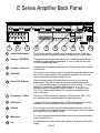
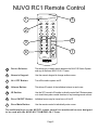
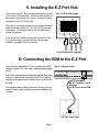
CD1 CD2 ALL OFF ONOFF MUTE SAT TUN1 VOL VOL TUN2 TUN3 E S E R I E S NV-E6MS/NV-E6XS M U LT I - S O U R C E / M U LT I - Z O N E A U D I O DISTRIBUTION SYSTEM OWNERS MANUAL DANGER EXPOSURE TO EXTREMELY HIGH NOISE LEVELS MAY CAUSE A PERMANENT HEARING LOSS. INDIVIDUALS VARY CONSIDERABLY TO NOISE-INDUCED HEARING LOSS, BUT NEARLY EVERYONE WILL LOSE SOME HEARING IF EXPOSED TO SUFFICIENTLY INTENSE NOISE FOR A SUFFICIENT TIME. THE U.S. GOVERNMENT'S OCCUPATIONAL SAFETY AND HEALTH ADMINISTRATION (OSHA) HAS SPECIFIED THE FOLLOWING PERMISSIBLE NOISE LEVEL EXPOSURES: DURATION PER DAY IN HOURS 8 6 4 3 2 1 SOUND LEVEL db FLOW RESPONSE 90 93 95 97 100 103 ACCORDING TO OSHA, ANY EXPOSURE WITHIN THE ABOVE PERMISSIBLE LIMITS COULD RESULT IN SOME HEARING LOSS. EAR PLUGS OR PROTECTORS IN THE EAR CANAL OR OVER THE EARS MUST BE WORN WHEN OPERATING THIS AMPLIFICATION SYSTEM IN ORDER TO PREVENT A PERMANENT HEARING LOSS. IF EXPOSURE IN EXCESS OF THE LIMITS AS PUT FORTH ABOVE, TO INSURE AGAINST POTENTIALLY HARMFUL EXPOSURE TO HIGH SOUND PRESSURE LEVELS, IT IS RECOMMENDED THAT ALL PERSONS EXPOSED TO EQUIPMENT CAPABLE OF INDUCING HIGH SOUND PRESSURE LEVELS, SUCH AS THIS AMPLIFICATION SYSTEM, BE PROTECTED BY HEARING PROTECTORS WHILE THIS UNIT IS IN OPERATION. THIS APPARATUS SHALL NOT BE EXPOSED TO DRIPPING OR SPLASHING. NO OBJECTS FILLED WITH LIQUIDS (SUCH AS VASES) SHALL BE PLACED ON THE APPARATUS. 1. 2. 3. 4. 5. 6. 7. 8. 9. 10. 11. 12. 13. 14. 15. IMPORTANT Read all safety and operating instructions before using this product. All safety and operating instructions should be kept for future reference. Obey all cautions in the operating instructions and on the back of the unit. All operating instructions should be followed. This product should not be used near water, i.e., bathtub, sink, swimming pool, wet basement, etc. This product should be located so that its position does not interfere with proper ventilation. It should not be placed flat against a wall or placed in a built-in enclosure that will impede the flow of cooling air. This product should not be placed near a source of heat, such as a stove, radiator, or another heat-producing amplifier. Connect only to a power supply of the type indicated on the back of the amplifier near the power supply cord. Do not break off the ground pin of the power supply cord. Power supply cords should always be handled carefully. Never walk on or place equipment on power supply cords. Periodically check cords for cuts or signs of stress, especially at the point where the cord exits the unit. The power supply cord should be unplugged when the unit is unused for long periods of time. If this product is to be mounted in an equipment rack, rear support should be provided. Metal parts and vinyl covering may be cleaned with a damp rag. Care should be taken so that objects do not fall and liquids are not spilled into the unit through the ventilation ports or any other openings. This unit should be checked by a qualified service technician if: A. The power supply cord or plug has been damaged. B. Anything has fallen or been spilled into the unit. C. The unit does not operate correctly. D. The unit has been dropped or the enclosure damaged. 16. The user should not attempt to service this equipment. All service work must be done by a qualified service technician for warranty repairs. TO AVOID ELECTRICAL SHOCK, DO NOT DISASSEMBLE. REFER SERVICING TO QUALIFIED PERSONNEL ONLY! CAUTION RISK OF ELECTRIC SHOCK CAUTION: TO REDUCE THE RISK OF ELECTRIC SHOCK, DO NOT REMOVE CHASSIS. NO USER-SERVICEABLE PARTS INSIDE. REFER SERVICING TO QUALIFIED SERVICE PERSONNEL. AV I S : R I S Q U E D E C H O C E L E C T R I Q U E - N E PA S O U V R I R . THIS SYMBOL IS INTENDED TO ALERT THE USER TO THE PRESENCE OF UNINSULATED DANGEROUS VOLTAGE WITHIN THE PRODUCTS ENCLOSURE THAT MAY BE OF SUFFICIENT MAGNITUDE TO CONSTITUTE A RISK OF ELECTRIC SHOCK TO PERSONS. CAUTION THIS AMPLIFIER HAS BEEN DESIGNED AND CONSTRUCTED TO PROVIDE ADEQUATE POWER RESERVE FOR PLAYING MODERN MUSIC THAT MAY REQUIRE OCCASIONAL PEAK POWER. EXTENDED OPERATION AT ABSOLUTE MAXIMUM POWER IS NOT RECOMMENDED BECAUSE THIS COULD DAMAGE THE ASSOCIATED LOUDSPEAKER SYSTEM. PLEASE BE AWARE THAT MAXIMUM POWER CAN BE OBTAINED. WITH VERY LOW SETTINGS OF THE MASTER VOLUME CONTROLS IF THE INPUT SIGNAL IS VERY STRONG. THIS SYMBOL IS INTENDED TO ALERT THE USER TO THE PRESENCE OF IMPORTANT OPERATING AND MAINTENANCE (SERVICING) INSTRUCTIONS IN THE LITERATURE ACCOMPANYING THE UNIT. NUVO Technologies Inc., 4940 Delhi Pike, Cincinnati, OH USA Tel: (866) 796-4904 Fax: (513) 347-2298 www.nuvotechnologies.com INTRODUCTION Congratulations on your purchase of the NUVO E Series audio distribution system. The E Series offers the newest in multi-zone/multi-source audio technology in an attractive, easy-to-install, and simple-to-use package. The E Series system is designed for the home owner. Its attractive, backlit keypads are elegant, easy-to-operate, and able to be customized for any installation. Included with each keypad are molded, screwless cover plates in white, ivory, almond and black, to best match your homes decor in every room. Also included with each keypad are thirty preprinted, interchangeable buttons, which allow the system to be specifically tailored for each installation. Using the E Series is as easy as the push of a button. The E6M amplifier is designed to be turned on and left on. Each zone can then be turned on or off independently, or all zones can be turned off simultaneously by using the ALL OFF command at any one of the keypads. Individual volume control and mute for each zone is also as easy as the push of a button. For the ultimate convenience, each E Series system includes an NV-RC1 infrared (IR)remote control. Complete control of audio source selection, volume, mute, or the innovative ALL OFF function are in the palm of your hand. Aim your RC1 remote at the IR receiver on the keypad, press the button for the command you desire, and the E Series does the rest. The built-in IR repeater allows for direct access to all of your audio source equipment by utilizing the individual audio components hand-held remote, or you can enjoy the convenience of having all of the commands of your audio source equipment in one universal learning remote. In addition, the RC1 remote is the perfect tool for teaching all of the functions of the E Series keypads to any learning remote control, so you have complete control of not only the E Series system, but of all your individual audio components from any room of the house. The following pages of the manual are step-by-step instructions for installing the E Series in your home. We suggest that you read and understand this installation guide in its entirety before installing your NUVO E Series system. Proper installation will insure years of audio enjoyment. NUVO Model NV-E6MS/NV-E6XS System Components NV-E6MS: Main Audio Distribution System Part # Description NV-E6M Six Source Distribution Amplifier NV-RC1 IR Remote Control NV-EKP Backlit Keypad NV-EZP Multi-port Connection NV-VEC Mini Mouse IR Emitter with Feedback LED NV-NC1 10 ft. Network Cable Qty 1 1 6 1 4 1 NV-E6XS: Expander Audio Distribution System Part # Description NV-E6X Expander Distribution Amplifier NV-RC1 IR Remote Control NV-EKP Backlit Keypad NV-AI2 Audiolink Interconnect Cable NV-DI3 Datalink Interconnect Cable Qty 1 1 6 1 1 Page 1 E Series Amplifier Front 1 2 3 1 POWER Button: The amplifier is designed to be turned on and remain on. The power button supplies power to the system. Each zone can then be turned on or off independently. 2 Stand By LED: This blue LED (light-emitting diode) will remain lit as long as the power button is engaged. Note that once the system is installed, it is designed to be left on. 3 Zone Status LED: These LEDs indicate the power status of each zone. Once in standby mode, each zone has the ability to be powered up or down independently. Page 2 E Series Amplifier Back Panel LINE OUT / SPEAKER L ZONE 1 R ZONE 2 LEFT RIGHT - + - + L R 20W/8 OHM X2 LINE OUT LEFT RIGHT - + - + L ZONE 3 R ZONE 4 LEFT RIGHT - + - + L R 20W/8 OHM X2 LINE OUT ZONE 5 LEFT RIGHT - + - + L R 20W/8 OHM X2 LINE OUT ZONE 6 LEFT RIGHT - + - + L R 20W/8 OHM X2 LINE OUT LEFT RIGHT - + - + DIAGNOSTIC CONTROL REFER TO MANUAL MUTE UNIT ON 0 LINE OUT 20W/8 OHM X2 LINE OUT INPUT SOURCES AUDIO OUTPUT L CONNECT TO NV-E6X 1 20W/8 OHM X2 IR EMITTER OUTPUTS +12V OUTPUT PULSE 3 N.O. G +12V G -INPUT- -OUTPUT- NETWORK ODD NUMBERED OUTPUTS ARE IDENTICAL (TIED TOGETHER) EVEN NUMBERED OUTPUTS ARE IDENTICAL (TIED TOGETHER) 2 MODEL NV-E6M SIX SOURCE SIX ZONE AUDIO DISTRIBUTION SYSTEM 120V 60Hz 300W KUSTOM INC. CINCINNATI, OH USA CONNECT TO NV-EZP DIGITAL OUTPUT CONNECT TO NV-E6X R 1 2 3 4 5 6 1 2 3 4 5 6 SUM 0215 2 1 3 4 5 6 7 8 9 10 1 Audio Source Inputs: The E Series amplifier accepts up to six audio sources. These can accept any audio component capable of supplying a line level signal. 2 Preamp LINEOUTS: Preamp lineouts for each zone allow you to easily use an additional amplifier to power additional speakers in a zone. Only use one pair of 8-ohm speakers per zone. 3 Speaker Outputs: Individual stereo speaker outputs provide 20 watts output per channel to each zone. 4 Audiolink: This multi-pin connection is used to transfer the audio information from the E Series main amplifier to the expander amplifier. This output is used to expand the system to twelve zones. 5 Routed IR Outputs: 6 Diagnostic LEDs: These four LEDs indicate the operation of the systems MPU. They also indicate correct communication through the system. 7 RJ45 Input: A single Cat-5 wire terminated with an RJ45 connector carries all the information from the individual zones to the main amplifier. 8 Datalink: This multi-pin connection transfers all the digital information from the main amplifier to the expander amplifier. This output is used to expand the system from six to twelve zones. 9 Mute Input: This input temporarily mutes the system when the pins are shorted by a dry contact closure. 10 AC: Detachable power cord connects the system to an external AC power supply. Page 3 These outputs transfer IR signals from the zones to your source components. They are routed odd and even so that when source 1, 3, or 5 is selected at any of the keypads, the IR outputs 1, 3, and 5 all flash IR commands. Similarly, when source 2, 4, or 6 is selected at any of the keypads, the IR outputs 2, 4, and 6 all flash. The Sum output always flashes IR commands regardless of the source selected. E Series Keypad 5 1 ALL OFF CD1 2 ONOFF CD2 6 MUTE SAT 3 TUN1 VOL VOL TUN2 4 7 8 TUN3 9 1 Cover Plate: The E Series keypad comes with four molded, replaceable covers in white, ivory, almond, and black. 2 Source Selection: The selected source button remains a backlit green until a new source is selected or the zone is turned off. A flashing source button indicates that the zone is muted. 3 Source Buttons: Each keypad comes with 30 preprinted replaceable buttons, so the system can be customized for the homeowner. 4 RJ45 Connection: Each keypad plugs into a dedicated Cat-5 wire using an RJ45 phone jack. The system operates on standard EIA/TIA 568A wiring. 5 ALL OFF Button: This turns the entire system off from any of the zone keypads. 6 Zone ON/OFF Button: Each zone can be individually turned on or off. 7 Mute Button: Each zone can be individually muted. The source selection button will flash indicating a muted zone. 8 Volume Button: The musics volume may be increased or decreased individually in each zone. 9 IR Receiver: Infrared commands can be used to control the E Series system as well as individual source functions. Page 4 NUVO RC1 Remote Control 1 2 TUNER 1 TUNER 2 TUNER 3 TUNER MULTI-ROOM Source 1 Source 2 1 2 3 Source 4 Source 5 Source 6 4 5 6 Source 7 Source 8 Source 9 8 9 7 5 Source 10 0 NUM MEM Power OFF 3 Source 3 ALL OFF ON Mode MON ON-OFF ST Band AM 6 MUTE FM Tune _ 4 + VOL + VOL Preset _ 7 MULTI ROOM TUNER NV-RC1 1 Device Selector: This allows you to easily switch between the NUVO E Series System and any of the three NUVO 3-IN-1 Tuners. 2 Numeric Keypad: Use the numeric keypad to change audio sources. 3 ALL OFF Button: Turn off the entire system via IR. 4 Volume Button: This allows IR control of the individual volume in each zone. 5 IR Emitter: Use the RC1 remotes IR emitter to directly control the E Series system or to teach the system control functions to any learning remote control. 6 Zone ON/OFF Button: Individual zones may be turned on or off via IR. 7 Zone Mute Button: Use the remote control to individually mute a zone. The additional keys on the NV-RC1 remote control not mentioned here are designed to be used with the NUVO NV-T3 AM/FM 3-IN-1 Tuner. Page 5 INSTALLING YOUR E SERIES SYSTEM I. Installing and Terminating Cables The basic installation requires two different types of cables. The keypads communicate with the E6M amplifier through Cat-5 data cable (4 twisted-pair). This cable is terminated at both ends with RJ45 connectors. The wiring scheme is standard EIA/TIA 568A, which is a standard for computer networking (see Fig. 1). These cables are routed in walls, crawl spaces, or attics, and go from the location of each keypad to the location of the E-Z Port hub. It is important to use a high-quality crimptool to assure the best possible connections. Testing each termination with a Cat-5 cable tester is crucial before installing the keypads. Improperly wired cable can damage the E6M amplifier or the keypads. The second type of cable used is AWG 16-2 or 16-4 speaker cable (AWG 14-gage can be used as well). These are routed in the walls, crawl spaces, or attics, and go from the location of a speaker to the location of the E6M amplifier. These cables are terminated at the E6M using the supplied 4-pin terminal block connectors. Using more than one pair of 8-ohm speakers is not recommended. Doing so could overheat and damage the amplifier and will void the warranty. When routing the Cat-5 and speaker cables, be careful to avoid running them in parallel with any other cables, such as AC, low voltage lighting, or home automation. Important Note: This unit generates large amounts of heat so please remember to allow for adequate ventilation. The top clearance must be at least 1 inch (25mm). Page 6 Fig. 1: 568A Cat-5 wiring scheme 1 2 3 Pair 2 4 5 Pair 1 6 7 8 Pair 4 Pair 3 After stripping the insulation off a portion of the Cat-5, untwist the wires and fan them out in the correct color order from left to right. Each of the RJ-45 connectors is terminated in the following pin order again from left to right. Pin # 1. Green Stripe 2. Green 3. Orange Stripe 4. Blue 5. Blue Stripe 6. Orange 7. Brown Stripe 8. Brown Note: Colors listed as Stripe are a white wire with a colored stripe. In other words, Orange Stripe is a white wire with orange stripes. II. Installing the E-Z Port Hub The location of the E-Z Port is mostly determined by where you locate the E6M amplifier. All Cat-5 cables should be terminated and routed to this location. Once this is done, installation of the E-Z Port is easy. Fig. 2: E-Z Port Backside Plug each of the keypad cables into one of fifteen available jacks on the back of the E-Z Port (Fig. 2). The jacks are numbered 1-15, although order is not important to the systems operation. Once all the Cat-5 cables are plugged into the E-Z Port, it can then be easily mounted into any commercially available dual-gang J-box or mud ring. Cat-5 cables from keypads. III. Connecting the E6M to the E-Z Port Once you have installed the E-Z Port, connect it to the E6M using the supplied 10 ft. Cat-5 cable supplied with the package (Fig. 3). Fig. 3: Network Input AUDIO OUTPUT CONNECT TO NV-E6X Both RJ45 connectors are wired identically with the 568A wiring scheme, so either end is connected to the E-Z Port, with the opposite end connecting to the Network Input on the back of the E6M. If the supplied network cable is too short or too long, you can make your own using the 568A wiring scheme outlined in Fig. 1, page 6. IR EMITTER OUTPUTS NETWORK +12V OUTPUT PULSE ODD NUMBERED OUTPUTS ARE IDENTICAL (TIED TOGETHER) EVEN NUMBERED OUTPUTS ARE IDENTICAL (TIED TOGETHER) 1 2 3 4 5 6 DIGITAL OUTPUT CONNECT TO NV-E6X SUM NV-NC1 Network Cable attaches the E-Z Port to the E6M E-Z Port Face Plate Page 7 CONNECT TO NV-EZP IV. Attaching Source Equipment to the E6M Each piece of source equipment is connected to the E6M amplifier with RCA cables. These go from the RCA output on the back of the source equipment to the RCA source inputs on the back of the E6M (Fig. 4). Fig. 4: Source Inputs INPUT SOURCES L R 1 2 3 4 5 6 Any unused inputs should be shorted-circuited with the supplied RCA shunts. This prevents any possibility of crosstalk between the sources. RCA Shunts are provided with the E6M and E6X packages and should be used to short-circuit any unused source inputs. V. Connecting the IR Emitters IR commands are transferred from the E6M amplifier to the source equipment via mini IR mouse emitters. Four of these are supplied with your E Series system. The emitters are plugged into the IR Emitter Outputs (Fig. 5). Outputs 1-6 are routed to the odd and even sources. In other words, if source 1, 3, or 5 is selected at the keypad, then emitters 1, 3, and 5 all flash, as does the Sum output. If source 2, 4, or 6 is selected, then emitters 2, 4, and 6 all flash, as does the Sum output. IR source routing allows you to have two identical sources and still have independent control of those two sources. If IR repeating is needed while the zone is turned OFF, only the 1, 3, 5, and Sum outputs are active. Page 8 Fig. 5: IR Emitter Outputs AUDIO OUTPUT CONNECT TO NV-E6X IR EMITTER OUTPUTS +12V OUTPUT PULSE ODD NUMBERED OUTPUTS ARE IDENTICAL (TIED TOGETHER) EVEN NUMBERED OUTPUTS ARE IDENTICAL (TIED TOGETHER) 1 2 3 4 5 The NV-VEC emitter flasher has an adhesive pad that attaches directly over the IR receiver window on the source equipment. 6 SUM VI. Connecting the E6M to the E6X Fig. 6: Audiolink and Datalink Connection E6X Amplifier Six additional zones can be added to the E6M. This is accomplished by adding the E6X expander unit. The connection is made by using the 37-pin Audiolink cable and the 26-pin Datalink cable supplied with the E6X package (Fig. 6). No other cables are necessary except the AC power cord. The speakers for the additional zones are attached to the E6X in the same way as the E6M using the supplied 4-pin terminal block connectors. AUDIO INPUT DIGITAL INPUT CONNECT TO NV-E6M CONNECT TO NV-E6M E6M Amplifier AUDIO OUTPUT CONNECT TO NV-E6X Caution: Using more than one pair of 8-ohm speakers per zone will damage the amplifier and void the warranty. NETWORK IR EMITTER OUTPUTS +12V OUTPUT PULSE CONNECT TO NV-EZP DIGITAL OUTPUT CONNECT TO NV-E6X ODD NUMBERED OUTPUTS ARE IDENTICAL (TIED TOGETHER) EVEN NUMBERED OUTPUTS ARE IDENTICAL (TIED TOGETHER) 1 2 3 4 5 6 SUM NV-DI3 Datalink Cable NV-AI2 Audiolink Cable VII. Installing the NV-EKP Keypads The NV-EKP keypads are the heart of the NUVO system. You are now ready to install the keypads, address them for each zone they will be controlling, adjust preset EQs, and group them as necessary, using a series of DIP switches located on the back of the keypad. The amplifier should be plugged into an AC outlet, and the Power button on the front panel turned on. The blue Stand By LED should be lit. The following section will be devoted to properly setting the eight DIP switches on each of the systems keypads. Page 9 Fig. 7: NV-EKP Keypad back panel EXTERNAL PROGRAMMER SW # ZN# SW # EQ SW # SRCE SW # VOL. RST. 5,6 (DB) 7 GROUP 8 @ ZN OFF 1,2,3,4 00 B,T+4 0 ON ON 0 1000 1 01 100+4 1 OFF 1 OFF 0100 2 10 10K+4 1100 3 0010 4 11 FLAT 1010 5 0110 6 0 O1 2 3 4 5 6 7 8 1110 7 N 0001 8 1 1001 9 0101 10 1101 11 DIP SWITCH ARRAY 0011 12 SW 1-4 SETS ADDRESS 1011 1* SW 5-6 SETS ZONE EQ 0111 2* SW 7 SETS GROUP ON/OFF 1111 3* SW 8 SETS VOLUME RESET * FOR SECOND KEYPAD VIII. Setting the NV-EKP DIP Switches The single most important aspect of the installation is to address the keypads correctly. The DIP switches labeled 1-4 are used to set the address (zone #) that this particular keypad will control. On the back of the keypad is a chart that indicates how to set these switches (Fig. 7). To set the keypad to control zone #1, set switch #1 down (1) and switches 2-4 up (0). This keypad will now control the speakers that are plugged into the Zone 1 speaker outputs (Fig. 8). Plug the keypad into the Cat-5 cable that is in zone #1. If you press the ON/OFF button, the keypad should light up and the LED on the front panel of the E6M amplifier for ZONE 1 should light up. Fig. 8: DIP switches 1-4 Zone 2 Zone 1 O1 N 2 3 4 5 6 7 8 Zone 3 O1 N 2 3 4 5 6 7 8 Zone 5 O1 N 2 3 4 5 6 7 8 Zone 7 O1 N 2 3 4 5 6 7 8 Zone 9 O1 N 2 3 4 5 6 7 8 Zone 11 O1 N The three addresses labeled ZN 1*, 2*, and 3* are set aside so that two keypads can be used in zones 1, 2, and 3. For instance, zone 1 can have two keypads: one addressed 1-0-0-0 and one addressed 1-0-1-1 (Fig. 9). This allows for a total of 15 keypads in a 12zoned system. 2 3 4 5 6 7 8 2 3 4 5 6 7 8 Zone 4 O1 N 2 3 4 5 6 7 8 Zone 6 O1 N 2 3 4 5 6 7 8 Zone 8 O1 N 2 3 4 5 6 7 8 Zone 10 O1 N 2 3 4 5 6 7 8 Zone 12 O1 N 2 3 4 5 6 7 8 Fig. 9: Zone 1, 2, and 3 additional keypads Zone 1* O1 N 2 3 4 5 6 7 8 Zone 3* O1 N Page 10 O1 N 2 3 4 5 6 7 8 Zone 2* O1 N 2 3 4 5 6 7 8 Switches 5 and 6 allow you to set a permanent EQ in that particular zone. You can set that zone to have a +4dB boost at 100Hz, a +4dB boost at 10kHz, a +4dB boost at both frequencies, or a flat response (Fig. 10). Fig. 10: Switches 5 & 6, Zone EQ Presets +4dB Boost at 100Hz O1 N 2 3 4 5 6 7 8 +4dB Boost at 100Hz and 10kHz O1 N Switch 7 allows you to group multiple keypads so that when a source is changed on one grouped keypad, all other grouped keypads will also change. This is handy for open floor plans where you might not want different sources interfering with each other. Source grouping is active when switch 7 is in the up position (Fig. 11). Switch 8 allows you to have the volume reset itself to a low level at power off. If this switch is in the up position, the audio volume will reset to a preset low level when power is restored to that zone. If the switch is in the down position, then the audio volume will return to its previous volume level when the zone was turned off (Fig. 12). Once the DIP switches for each zone are set, they can be installed in most standard J-boxes (we recommend the Slater model # S1-18-W), but not all. The width of the keypad is 51mm or 2 inches. It is important to make sure that the keypads are compatible with the J-boxes being used in the installation. Page 11 2 3 4 5 6 7 8 +4dB Boost at 10kHz O1 N 2 3 4 5 6 7 8 Flat Response O1 N 2 3 4 5 6 7 8 Fig. 11: Switch 7, Zone Grouping Zone Group ON O1 N 2 3 4 5 6 7 8 Zone Group OFF O1 N 2 3 4 5 6 7 8 Fig. 12: Switch 8, Zone Volume Preset Volume low-level preset Set volume level O1 N 2 3 4 5 6 7 8 O1 N 2 3 4 5 6 7 8 IX. NV-RC1 REMOTE CONTROL TUNER MULTI-ROOM 3 Source 3 TUNER 1 TUNER 2 TUNER 3 2 6 Source 6 Source 2 Source 5 1 5 Source 1 Source 4 Source 8 Source 9 4 The RC1 can also be used to teach any learning remote control all of its internal commands (Fig. 13). Fig. 13: NV-RC1 Remote Source 7 All NUVO products come with the wireless remote. This remote will control all functions of the NV-EKP keypad. To control the E Series, move the Device Selector switch on the upper right side of the RC1 to Multi-room. Now the numeric buttons will select the source (#1-#6), and the five buttons in the Multi-room section will correspond exactly to the EKP keypad. NV-RC1 Remote Learning Remote Refer to the owners manual for your learning remote control to place that device in learn mode. Once you have chosen a page for storing the E Series internal functions, i.e., source selection, volume, etc., you can then easily teach these functions to your learning remote and have complete wireless control of your NUVO system. X. Using the Mute and Unit On Pins The Mute input can be used to mute the system by providing a dry closure to these pins (Fig. 14). In other words, any short-circuit across this input will temporarily mute the system. This can be useful for providing a mute when the phone, or doorbell ring. Most home automation devices can provide this type of output. The Unit On pins will provide a +12Vdc at 100mA output when any zone is ON. This can be used via a signalsensing power strip to switch on other equipment when the E Series system is being used. Page 12 Fig. 15: Mute In and Unit On Pins DIAGNOSTIC REFER TO MANUAL 0 1 2 3 CONTROL MUTE N.O. UNIT ON G +12V G -INPUT- -OUTPUT- The Mute is an external mute switch. This can be as simple as a 2-conductor wire from a relay closure on a home automation system or phone system to the E6M unit. This will short-circuit the input, and mute the system when the doorbell or phone is rung. XI. MPU Diagnostic LEDs The MPU Diagnostic LEDs serve several functions. One function is the lowest assignable address. This is an aid in sequentially assigning the appropriate address on each keypad. When the system is turned on, and none of the keypads have been addressed, the diagnostic LED 0 should flash every 0.8 seconds. This means the first DIP switch on the keypad should be set in the down position, and the other three should be in the up position. This sets that keypad for zone 1.You will then see diagnostic LED 1 begin to flash. This is indicating the next available zone setting, which is the second DIP switch in the down position and the other three in the up position. The next available address would then be zone 3, which is the first two DIP switches in the down position and the third and fourth DIP switches in the up position, which is indicated by diagnostic LED 0 and LED 1 flashing simultaneously. As each keypad is set, the LEDs will continue to cycle to the next address, with the flashing LEDs indicating which of the four address DIP switches should be in the down position (Fig. 15). Important Note: Once a keypad has been addressed, it should be left hooked up to the system. This will keep the diagnostic LEDs accurately displaying the next available address. If the MPUs bus transceiver is functioning properly, one or more of the Diagnostic LEDs will flash continually every 0.8 seconds. If the MPUs bus transceiver sees a short-circuit on the bus, all four LEDs will flash ON twice every 0.8 seconds. If the MPU is not processing normally due to a malfunction of the micro controller, all four LEDs will flash ON three times every 0.8 seconds. Page 13 Fig. 15: Diagnostic LEDs DIAGNOSTIC REFER TO MANUAL 0 1 2 3 CONTROL MUTE N.O. UNIT ON G +12V G -INPUT- -OUTPUT- A steadily flashing LED indicates a properly functioning MPU. If all four LEDs are flashing twice every 0 .8 seconds, there is a short-circuit that is most often a result of improperly wired Cat-5 cables. If all four LEDs flash three times every 0.8 seconds, there is a malfunction of the micro controller. If this should occur, please contact NUVO for proper warranty service. XII. Changing the Buttons on the NV-EKP The NV-EKP keypads come with 30 preprinted, interchangeable buttons. These have a variety of audio source labels for customizing the E Series system to match the audio components being used. Included in these are six genre buttons, such as Classical, Rock, Jazz, etc. These can be useful for components like CD changers or satellite receivers that can be set up for specific styles of music. The keypads have a screwless cover plate that is easily removed with a small screwdriver. Under that plate is another smaller plate that holds the buttons in place. This is also easily removed with a small screwdriver. Once that is removed, the buttons can then be replaced either individually by tearing the perforation or as a complete strip of six buttons. Align the buttons you wish to use on the keypad and snap the internal cover plate back over them. Snap the cover plate back on, and the keypad is now ready to be installed in its location in the wall (Fig 16). Fig. 16: Changing Keypad Buttons CD 1 CD 2 ALL OFF ONOFF MUTE Using a small screwdriver, release the tab holding the internal cover plate to the keypad, and remove it. SAT VOL TUN 1 VOL TUN 2 TUN 3 The buttons have rubber tabs designed to fit into holes in the keypads PC board. XIII. NV-MI1 Mute Interface The NV-MI1 Mute Interface is an additional accessory that can be used to temporarily mute all zones whenever the phone rings or the doorbell chimes. No external power is needed for this purpose. To mute the system when the doorbell chimes, simply run a pair of doorbell wires from the chime terminals to the connector on the MI1 labeled DOORBELL A or DOORBELL B (or both). Then connect a pair of wires from the Mute Out jack on the MIB-1 to the Mute pins on the back of the E6M amplifier (Fig. 17). To mute the system when the phone rings, simply connect a standard four conductor telephone line cord (for two phone lines) into the Telco In jack, and then connect a pair of wires from the Mute Out jack on the MIB-1 to the Mute In pins on the back of the E6M amplifier (Fig. 17). The MI1 is not supplied with the E6M or the E6X packages. Page 14 Fig. 17: NV-MI1: Mute Interface DIAGNOSTIC REFER TO MANUAL 0 NV-MIB1 BACK TO E6m FRONT TELCO IN DOORBELL I A B 1 2 3 CONTROL MUTE UNIT ON +12V G -INPUT- -OUTPUT- The MI1 will accept two phone lines and two doorbell signals, and combines them to one two-conductor connection to the E6Ms Mute input. Up to two phone lines from the homes telephone service can be connected to the MI1 via typical four-conductor phone line with an RJ11 connector. Two doorbells can be connected to the MI1 from the doorbell chimes using two-conductor wire. Troubleshooting Symptom Probable Cause Remedy When a keypad is plugged in, there is a loud pop through the speakers and the keypad does not work. Improperly wired Cat-5 cable. Check that you are using the 568A wiring standard (See Section I. Installing and Terminating Cables). My keypad is lit, but nothing happens when I press a button. Assigning identical addresses to more than one keypad usually causes this. Each keypad MUST have a unique address as set by DIP switches 1-4 (Section VIII. Setting the NV-EKP Keypads). There are 15 valid addresses available to any 12-zone system. When there is a lull in the music, I can hear other sources playing in my speakers. This is a result of open source inputs on the back of the E6M. Place the supplied RCA input shunts in any unused RCA source inputs (Section IV. Attaching Source Equipment to the E6M). The RC1 wireless remote will not operate the E6M. The RC1 is in Tuner mode or there are dead or improperly installed batteries. Make sure the Device Selector switch is in the Multi-room position and that the batteries are installed properly and are good. In certain zones the repeater does not seem to work properly. If the equipment that you are trying to control is in the zone in question and it is in the line of sight with your wireless remote, i.e., a rack with a glass door, then you are creating interference at the IR sensor of the source equipment. Page 15 Verify that the rack equipment can be controlled through the keypad by blocking the IR sensor of the source equipment (but not the emitter) with your hand. If it works, then either move the keypad or block the sensor permanently. NUVO NV-E6M Specifications Power Amplifier Section Continuous Average Output Power Two channels driven 30-20kHz @ 1% THD Rated Distortion (1/2 power) Rated Impedance Damping Factor Line Output Level (at full output) Frequency Response (30-20kHz) Preamplifier Section Input Impedance Input Sensitivity for rated power Input Overload 23W 0.4% 8 Ohms 50+ 4.5V RMS +/-3dB Power Requirements 120VAC/240VAC 50/60Hz Power Supply Power Consumption 382VA (333W) all channels driven to full-rated power Power Consumption 177VA (140W) 1/8 power average operating conditions Power Consumption 37VA (30W) no signal USA Safety Listing (ANSI/UL-6500) Canada Safety Listing (CAN/CSA C22.2 NO. 1) CE Listing 50k 330mV RMS Physical Specifications 88 x 430 x325 3V RMS Unit Size in millimeters (H x W x D) Unit Size 3.5 x 17 x12.75 IR System in inches (H x W x D) Source Outputs 7 180 x 520 x400 Output Drive Current 100mA Shipping Size in millimeters (H x W x D) Output Drive Voltage 12V 7.5 x 20.5 x 15.5 Compatible with single and dual emitters Yes Shipping Size in inches (H x W x D) Unit Weight in kilograms 8.6 Unit Weight in pounds 19.0 Shipping Weight in kilograms 10.0 Shipping Weight in pounds 22.0 Warranty NUVO Technologies warrants this product to be free of defects in workmanship or material for a period of three (3) years from the original date of purchase. This warranty applies to the original purchaser only and is not transferable. This warranty is subject to the following conditions and exclusions: -Defects caused by wear and tear, misuse, or neglect are not covered by this warranty. -This warranty will be void if: a. The unit has been altered or modified. b. The serial number has been removed or defaced. c. Original purchase is not from an Authorized NUVO Dealer. d. The warranty card is not completely filled out and mailed within 10 days of the original purchase. Neither NUVO Technologies, nor NUVO dealers are liable for any incidental or consequential damages resulting from any defect in or failure of NUVO Technologies products. This warranty gives the original owner of NUVO Technologies products specific legal rights, and he or she may also have other rights which vary from state to state. This warranty is expressly in lieu of all other agreements and warranties, expressed or implied, except as may be otherwise required by law. Page 16 NUVO Technologies Inc., 4940 Delhi Pike, Cincinnati, OH USA Tel: (866) 796-4904 Fax: (513) 347-2298 www.nuvotechnologies.com