1
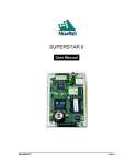
SUPERSTAR II
User Manual
OM-20000077
Rev 3
SUPERSTAR II User Manual
Publication Number:
Revision Level:
Revision Date:
OM-20000077
3
2004/03/11
Proprietary Notice
Information in this document is subject to change without notice and does not represent a commitment on the part of
NovAtel Inc. The software described in this document is furnished under a licence agreement or non-disclosure
agreement. The software may be used or copied only in accordance with the terms of the agreement. It is against the
law to copy the software on any medium except as specifically allowed in the license or non-disclosure agreement.
No part of this manual may be reproduced or transmitted in any form or by any means, electronic or mechanical,
including photocopying and recording, for any purpose without the express written permission of a duly authorized
representative of NovAtel Inc.
The information contained within this manual is believed to be true and correct at the time of publication.
NovAtel is a registered trademark of NovAtel Inc.
SUPERSTAR, FlexPak-SSII and StarView are trademarks of NovAtel Inc.
All other brand names are trademarks of their respective holders.
© Copyright 2003-2004 NovAtel Inc. All rights reserved.
Unpublished rights reserved under International copyright laws.
2
SUPERSTAR II User Manual Rev 3
Table of Contents
Software License
Customer Service
Notices
Warranty Policy
Foreword
1 Introduction
7
9
10
12
13
14
1.1 SUPERSTAR II GPS Card ............................................................................................................ 14
1.2 FlexPak-SSII.................................................................................................................................. 15
2 Receiver Specifications
17
2.1 System Architecture....................................................................................................................... 17
2.2 Physical Characteristics................................................................................................................. 17
2.2.1 Radio Frequency (RF) Section............................................................................................. 17
2.2.2 Digital Electronics Section.................................................................................................... 17
2.3 Enclosure and Wiring Harness ...................................................................................................... 18
2.4 GPS Antenna................................................................................................................................. 18
2.4.1 Optional LNA Power Supply................................................................................................. 18
2.5 Principal Power Supply.................................................................................................................. 18
2.6 Data Communications Equipment ................................................................................................. 18
3 Installation
19
3.1 Electrostatic Discharge .................................................................................................................. 20
3.2 Equipment Interconnection ............................................................................................................ 20
3.2.1 Serial Connection ................................................................................................................. 20
3.2.2 Power Connection ................................................................................................................ 21
3.3 Installation Considerations............................................................................................................. 21
3.3.1 Antenna Location ................................................................................................................. 21
3.3.2 Base Station Location .......................................................................................................... 21
3.3.3 Data Link .............................................................................................................................. 22
3.3.4 Base Station and Rover Units Separation............................................................................ 22
3.4 Connectors and Connector Pins Assignment ................................................................................ 22
3.4.1 J1 Interface and Power Connector....................................................................................... 22
3.4.2 Serial Data Interface ............................................................................................................ 23
3.4.3 RF Connector (J2)................................................................................................................ 23
3.4.4 Memory Back-Up ................................................................................................................. 24
3.5 Protocol Selection and Non Volatile Memory ................................................................................ 24
3.5.1 Non Volatile Memory ............................................................................................................ 26
3.6 Default Configuration ..................................................................................................................... 26
3.7 Installation Overview...................................................................................................................... 27
4 Operation
28
4.1 Communications with the Receiver ............................................................................................... 29
4.1.1 Serial Port Default Settings .................................................................................................. 29
4.2 Getting Started............................................................................................................................... 29
4.2.1 Power-Up Information .......................................................................................................... 30
4.2.2 Boot Information ................................................................................................................... 30
4.2.3 Operational Information........................................................................................................ 30
4.3 Data Requests ............................................................................................................................... 31
4.4 Configurable Parameters............................................................................................................... 31
SUPERSTAR II User Manual Rev 3
3
Table of Contents
4.4.1 Mask Angle........................................................................................................................... 31
4.4.2 GPS Antenna Position.......................................................................................................... 31
4.5 Receiver States ............................................................................................................................. 31
4.5.1 Non-Operational State.......................................................................................................... 31
4.5.2 Operational States................................................................................................................ 31
4.6 Built-In Status Tests....................................................................................................................... 33
4.7 DATUM Support ............................................................................................................................ 34
5 Message Formats
35
5.1 RTCM-Format Messages .............................................................................................................. 35
5.1.1 RTCM1 Differential GPS Corrections (Fixed)....................................................................... 35
5.1.2 RTCM2 Delta Differential GPS Corrections (Fixed) ............................................................. 36
5.1.3 RTCM9 Partial Satellite Set Differential Corrections ............................................................ 36
5.2 NMEA Format Data Messages ...................................................................................................... 37
6 Positioning Modes of Operation
38
6.1 Single-Point or Autonomous .......................................................................................................... 38
6.1.1 GPS System Errors .............................................................................................................. 38
6.2 Satellite-Based Augmentation System (SBAS) ............................................................................. 39
6.2.1 SBAS Receiver..................................................................................................................... 40
6.2.2 SBAS Messages .................................................................................................................. 40
7 Troubleshooting
42
APPENDICES
A Technical Specifications
B FlexPak-SSII Specifications
C Antenna Specifications
D Standards/References
E TTFF and Satellite Acquisition
F Updating Receiver Firmware
G GPS Overview
H Glossary of Terms
I Acronyms
4
44
49
56
62
63
64
67
76
80
SUPERSTAR II User Manual Rev 3
Tables
1
2
3
4
5
6
7
8
9
10
11
12
13
14
15
16
Related Publications .................................................................................................................... 13
Minimum J1 Connections ............................................................................................................. 22
Use of Discretes ........................................................................................................................... 25
Discretes IP2 and IP3 functions ................................................................................................... 25
Non-Volatile Memory Data ........................................................................................................... 26
Cable Lengths Vs. Gain ............................................................................................................... 42
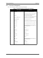
J1 Interfaces and Power Connector Pin Assignment ................................................................... 47
I/O Signals Voltage Limits ............................................................................................................ 48
FlexPak Status Indicators ............................................................................................................ 50
FlexPak COM Ports Pin-Out Descriptions .................................................................................. 50
Coaxial Cable Specifications ........................................................................................................ 56
Antenna Gain Depending on Cable Length Required .................................................................. 57
Typical Current Consumption Versus Antenna Gain ................................................................... 57
Recommended Geodetic Active Antennas .................................................................................. 58
Recommended Active Antennas .................................................................................................. 58
Passive Antenna Specifications (Patch Element) ........................................................................ 59
SUPERSTAR II User Manual Rev 3
5
Figures
1
2
3
4
5
6
7
8
9
10
11
12
13
14
15
16
17
18
19
20
21
22
23
24
25
26
27
6
SUPERSTAR II Receiver .............................................................................................................. 14
FlexPak-SSII Enclosure ................................................................................................................ 15
Receiver Block Diagram................................................................................................................ 17
Typical System Configuration........................................................................................................ 19
Basic Setup ................................................................................................................................... 27
Typical Operational Configuration ................................................................................................. 28
The SBAS Concept ....................................................................................................................... 40
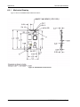
SUPERSTAR II Dimensions.......................................................................................................... 46
FlexPak Power Cable.................................................................................................................... 51
FlexPak 13-Pin Serial Cable ......................................................................................................... 52
Differential GPS Setup .................................................................................................................. 54
GPS Antenna 201-990146-716 (MCX, +12 dB) ............................................................................ 59
GPS Antenna 201-990147-606 (+26 dB) ...................................................................................... 60
Coaxial Cable Assembly ............................................................................................................... 60
GPS Antenna 201-990147-432 (1575 MHz) and 201-990144-807 (Pre-Amplifier)....................... 61
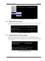
Update Registration Window in DOS ............................................................................................ 64
Paste the Registration Key into the DOS Window ........................................................................ 65
Configuration Accepted ................................................................................................................. 65
Update Utility Activation ................................................................................................................ 65
End of Programming Session........................................................................................................ 66
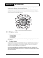
NAVSTAR Satellite Orbit Arrangement ......................................................................................... 67
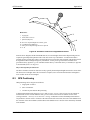
Illustration of Receiver Height Measurements............................................................................... 69
Accuracy versus Precision ............................................................................................................ 70
Example of Differential Positioning................................................................................................ 71
Illustration of GPS Signal Multipath............................................................................................... 72
GPS Signal Multipath vs. Increased Antenna Height .................................................................... 74
Illustration of Quadrifilar vs. Microstrip Patch Antennas................................................................ 75
SUPERSTAR II User Manual Rev 3
Software License
Software License
BY INSTALLING, COPYING, OR OTHERWISE USING THE SOFTWARE PRODUCT, YOU AGREE TO BE
BOUND BY THE TERMS OF THIS AGREEMENT. IF YOU DO NOT AGREE TO THE TERMS OF THIS
AGREEMENT, DO NOT INSTALL, COPY OR USE THE SOFTWARE PRODUCT.
1.
2.
3.
4.
5.
6.
License: NovAtel Inc. ("NovAtel") grants you a non-exclusive, non-transferable license (not a sale) to use
one copy of the enclosed NovAtel software on a single computer, and only with the product it was supplied
with. You agree not to use the software for any purpose other than the due exercise of the rights and
licences hereby agreed to be granted to you.
Copyright: NovAtel owns, or has the right to sublicense, all copyright, trade secret, patent and other
proprietary rights in the software and the software is protected by national copyright laws, international
treaty provisions and all other applicable national laws. You must treat the software like any other
copyrighted material except that you may either (a) make one copy of the software solely for backup or
archival purposes, the media of said copy shall bear labels showing all trademark and copyright notices
that appear on the original copy, or (b) transfer the software to a single hard disk provided you keep the
original solely for backup or archival purposes. You may not copy the product manual or written materials
accompanying the software. No right is conveyed by this Agreement for the use, directly, indirectly, by
implication or otherwise by Licensee of the name of NovAtel, or of any trade names or nomenclature used
by NovAtel, or any other words or combinations of words proprietary to NovAtel, in connection with this
Agreement, without the prior written consent of NovAtel.
Patent Infringement: NovAtel shall not be liable to indemnify the Licensee against any loss sustained by it
as the result of any claim made or action brought by any third party for infringement of any letters patent,
registered design or like instrument of privilege by reason of the use or application of the software by the
Licensee or any other information supplied or to be supplied to the Licensee pursuant to the terms of this
Agreement. NovAtel shall not be bound to take legal proceedings against any third party in respect of any
infringement of letters patent, registered design or like instrument of privilege which may now or at any
future time be owned by it. However, should NovAtel elect to take such legal proceedings, at NovAtel's
request, Licensee shall co-operate reasonably with NovAtel in all legal actions concerning this license of
the software under this Agreement taken against any third party by NovAtel to protect its rights in the
software. NovAtel shall bear all reasonable costs and expenses incurred by Licensee in the course of cooperating with NovAtel in such legal action.
Restrictions: You may not: (1) copy (other than as provided for in paragraph 2), distribute, transfer, rent,
lease, lend, sell or sublicense all or any portion of the software; (2) modify or prepare derivative works of
the software; (3) use the software in connection with computer-based services business or publicly display
visual output of the software; (4) transmit the software over a network, by telephone or electronically using
any means; or (5) reverse engineer, decompile or disassemble the software. You agree to keep confidential
and use your best efforts to prevent and protect the contents of the software from unauthorized disclosure
or use.
Term and Termination: This Agreement and the rights and licences hereby granted shall continue in force
in perpetuity unless terminated by NovAtel or Licensee in accordance herewith. In the event that the
Licensee shall at any time during the term of this Agreement: i) be in breach of its obligations hereunder
where such breach is irremediable or if capable of remedy is not remedied within 30 days of notice from
NovAtel requiring its remedy; or ii) be or become bankrupt or insolvent or make any composition with its
creditors or have a receiver or manager appointed of the whole or any part of its undertaking or assets or
(otherwise as a solvent company for the purpose of and followed by an amalgamation or reconstruction
hereunder its successor shall be bound by its obligations hereunder) commence to be wound up; or iii) be
acquired or otherwise come under the direct or indirect control of a person or persons other than those
controlling it, then and in any event NovAtel may forthwith by notice in writing terminate this Agreement
together with the rights and licences hereby granted by NovAtel. Licensee may terminate this Agreement
by providing 30 days prior written notice to NovAtel. Upon termination, for any reasons, the Licensee
shall promptly, on NovAtel's request, return to NovAtel or at the election of NovAtel destroy all copies of
any documents and extracts comprising or containing the software. The Licensee shall also erase any
copies of the software residing on Licensee's computer equipment. Termination shall be without prejudice
to the accrued rights of either party, including payments due to NovAtel. This provision shall survive
termination of this Agreement howsoever arising.
Warranty: For 90 days from the date of shipment, NovAtel warrants that the media (for example, compact
SUPERSTAR II User Manual Rev 3
7
Software License
disk) on which the software is contained will be free from defects in materials and workmanship. This
warranty does not cover damage caused by improper use or neglect. NovAtel does not warrant the contents
of the software or that it will be error free. The software is furnished "AS IS" and without warranty as to
the performance or results you may obtain by using the software. The entire risk as to the results and
performance of the software is assumed by you.
7. Indemnification: NovAtel shall be under no obligation or liability of any kind (in contract, tort or
otherwise and whether directly or indirectly or by way of indemnity contribution or otherwise howsoever)
to the Licensee and the Licensee will indemnify and hold NovAtel harmless against all or any loss,
damage, actions, costs, claims, demands and other liabilities or any kind whatsoever (direct, consequential,
special or otherwise) arising directly or indirectly out of or by reason of the use by the Licensee of the
software whether the same shall arise in consequence of any such infringement, deficiency, inaccuracy,
error or other defect therein and whether or not involving negligence on the part of any person.
8. For software UPDATES and UPGRADES, and regular customer support, contact the NovAtel GPS
Hotline at 1-800-NOVATEL (U.S. or Canada only), or 403-295-4900, or fax 403-295-4901, e-mail to
[email protected], visit our website http://www.novatel.ca or write to:
NOVATEL INC.
CUSTOMER SERVICE DEPT.
1120 - 68 AVENUE NE,
CALGARY, ALBERTA, CANADA T2E 8S5
9. Disclaimer of Warranty and Limitation of Liability:
a. THE WARRANTIES IN THIS AGREEMENT REPLACE ALL OTHER WARRANTIES, EXPRESS OR IMPLIED, INCLUDING ANY WARRANTIES OF MERCHANTABILITY OR FITNESS FOR A PARTICULAR PURPOSE. NovAtel DISCLAIMS AND EXCLUDES ALL
OTHER WARRANTIES. IN NO EVENT WILL NovAtel's LIABILITY OF ANY KIND INCLUDE ANY SPECIAL, INCIDENTAL OR CONSEQUENTIAL DAMAGES, INCLUDING
LOST PROFITS, EVEN IF NovAtel HAS KNOWLEDGE OF THE POTENTIAL LOSS OR
DAMAGE.
a. NovAtel will not be liable for any loss or damage caused by delay in furnishing the software or any
other performance under this Agreement.
a. NovAtel's entire liability and your exclusive remedies for our liability of any kind (including liability for negligence) for the software covered by this Agreement and all other performance or nonperformance by NovAtel under or related to this Agreement are to the remedies specified by this
Agreement.
THIS AGREEMENT IS GOVERNED BY THE LAWS OF THE PROVINCE OF ALBERTA, CANADA. EACH
OF THE PARTIES HERETO IRREVOCABLY ATTORNS TO THE JURISDICTION OF THE COURTS OF THE
PROVINCE OF ALBERTA.
8
SUPERSTAR II User Manual Rev 3
Customer Service
Customer Service
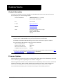
Contact Information
If you have any questions or concerns regarding your SUPERSTAR II, please contact NovAtel Customer
Service using any one of the following methods:
NovAtel GPS Hotline:
1-800-NOVATEL (U.S. or Canada)
403-295-4900 (International)
Fax:
403-295-4901
E-mail:
[email protected]
Website:
www.novatel.com
Write:
NovAtel Inc. Customer Service Dept.
1120 - 68 Avenue NE
Calgary, Alberta, Canada
T2E 8S5
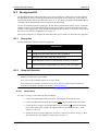
Before contacting NovAtel Customer Service regarding software concerns, please do the following:
1. Issue the Erase NVM command, Message ID# 99, with value 0 to reset all NVM.
(For details on individual commands and logs, refer to the L1 GPS Firmware Reference Manual)
2. Log the following data requests to a file on your PC for 30 minutes
Receiver Status, ID# 49
Ephemeris Data, ID# 22
Measurement Block, ID# 23
HW/SW Identification, ID# 45
one shot
continuous
1 Hz
one shot
3. Send the file containing the log to NovAtel Customer Service, using either the NovAtel ftp site at ftp://
ftp.novatel.ca/incoming or the [email protected] e-mail address.
Firmware Updates
Firmware updates are firmware revisions to an existing model, which improves basic functionality of the GPS
receiver. See also Appendix F, Updating Receiver Firmware on Page 64.
Firmware upgrades are firmware releases, which increase basic functionality of the receiver from one model to
a higher level model type. When available, upgrades may be purchased at a price, which is the difference
between the two model types on the current NovAtel GPS Price List plus a nominal service charge.
If you need further information, please contact NovAtel using one of the methods given above.
SUPERSTAR II User Manual Rev 3
9
Notices
Notices
The following notices apply to the SUPERSTAR II card.
The receiver operates within the performance requirements specified herein.
Electrostatic Discharge
This equipment contains components which are sensitive to damage by electrostatic discharge (ESD).
A label bearing an ESD marking appears on packaging for the card.
When cards have to be replaced or returned for service the following precautions should be observed:
1. Handle the card as little as possible. Do not touch the leads, pin or tracks while handling.
2. Keep spare cards in the ESD protective packing until they are ready for use.
3. Discharge static before handling the cards (removal or replacement) by touching a grounded
metallic surface such as a rack or cabinet hardware. Use of wrist strap grounded through a one
mega-ohm resistor is preferred when handling cards. (This ground should be the same as the
equipment ground).
4. Do not slide static-sensitive cards over any surface.
5. Clothing must not come in contact with components or assemblies. Wear short sleeves or roll-up
long sleeves.
6. Package parts properly for storage or transportation. Cards which are removed from the equipment
should be placed into ESD protective packing immediately. Do not place any paper, card or other
plastic inside the ESD protective packing.
7. When packing these cards for storage or transportation, keep them in the bag. Fold over and seal
the mouth of the bag to keep out any static generating packing material (for example foamed
polystyrene). Pack around the bag firmly to prevent motion which could generate static.
The following notices apply to the FlexPak-SSII.
FCC Notice
This equipment has been tested and found to comply with the limits for a Class A digital device, pursuant to
Part 15 of the FCC Rules. These limits are designed to provide reasonable protection against harmful
interference when the equipment is operated in a commercial environment. This equipment generates, uses,
and can radiate radio frequency energy and, if not installed and used in accordance with the instruction manual,
may cause harmful interference to radio communications. Operation of this equipment in a residential area is
likely to cause harmful interference in which case the user will be required to correct the interference at his
own expense.
If this equipment does cause harmful interference to radio or television reception, which can be determined by
turning the equipment off and on, the user is encouraged to try to correct the interference by one or more of the
following measures:
• Reorient or relocate the receiving antenna.
• Increase the separation between the equipment and receiver.
• Connect the equipment into an outlet on a circuit different from that to
which the receiver is connected.
• Consult the dealer or an experienced radio/TV technician for help.
10
SUPERSTAR II User Manual Rev 3
Notices
WARNING: Changes or modifications to this equipment not expressly approved by NovAtel Inc. could
result in violation of Part 15 of the FCC rules.
CE Notice
The enclosures carry the CE mark.
WARNING: This is a Class B product. In a domestic environment this product may cause radio
interference in which case the user may be required to take adequate measures.
EMC Common Regulatory Testing
•
•
•
•
•
•
•
•
•
EN55022
CISPR 22
EN 50081-1
EN 50082-1
EN 61000-4-2
EN 61000-4-3
EN 61000-4-4
EN 61000-4-6
EN 61000-4-8
SUPERSTAR II User Manual Rev 3
Radiated and Conducted Emissions
Class B
Generic Emissions Class B
Generic Immunity Class B
Electrostatic Discharge Immunity
Radiated RF EM Field Immunity Test
Electrical Fast Transient/Burst Test
Conducted Immunity
Magnetic Field Immunity
11
Warranty Policy
Warranty Policy
NovAtel Inc. warrants that its Global Positioning System (GPS) products are free from defects in materials and
workmanship, subject to the conditions set forth below, for the following periods of time:
SUPERSTAR II GPSCard Receiver
FlexPak-SSII
GPSAntenna™ Series
Cables and Accessories
Software Support
One (1) Year
One (1) Year
One (1) Year
Ninety (90) Days
One (1) Year
Date of sale shall mean the date of the invoice to the original customer for the product. NovAtel’s responsibility respecting
this warranty is solely to product replacement or product repair at an authorized NovAtel location only.
Determination of replacement or repair will be made by NovAtel personnel or by technical personnel expressly authorized
by NovAtel for this purpose.
THE FOREGOING WARRANTIES DO NOT EXTEND TO (I) NONCONFORMITIES, DEFECTS
OR ERRORS IN THE PRODUCTS DUE TO ACCIDENT, ABUSE, MISUSE OR NEGLIGENT USE
OF THE PRODUCTS OR USE IN OTHER THAN A NORMAL AND CUSTOMARY MANNER,
ENVIRONMENTAL CONDITIONS NOT CONFORMING TO NOVATEL’S SPECIFICATIONS, OR
FAILURE TO FOLLOW PRESCRIBED INSTALLATION, OPERATING AND MAINTENANCE
PROCEDURES, (II) DEFECTS, ERRORS OR NONCONFORMITIES IN THE PRODUCTS DUE TO
MODIFICATIONS, ALTERATIONS, ADDITIONS OR CHANGES NOT MADE IN ACCORDANCE
WITH NOVATEL’S SPECIFICATIONS OR AUTHORIZED BY NOVATEL, (III) NORMAL WEAR
AND TEAR, (IV) DAMAGE CAUSED BY FORCE OF NATURE OR ACT OF ANY THIRD PERSON,
(V) SHIPPING DAMAGE; OR (VI) SERVICE OR REPAIR OF PRODUCT BY THE DEALER WITHOUT PRIOR WRITTEN CONSENT FROM NOVATEL. IN ADDITION, THE FOREGOING WARRANTIES SHALL NOT APPLY TO PRODUCTS DESIGNATED BY NOVATEL AS BETA SITE
TEST SAMPLES, EXPERIMENTAL, DEVELOPMENTAL, PREPRODUCTION, SAMPLE, INCOMPLETE OR OUT OF SPECIFICATION PRODUCTS OR TO RETURNED PRODUCTS IF THE
ORIGINAL IDENTIFICATION MARKS HAVE BEEN REMOVED OR ALTERED. THE WARRANTIES AND REMEDIES ARE EXCLUSIVE AND ALL OTHER WARRANTIES, EXPRESS OR
IMPLIED, WRITTEN OR ORAL, INCLUDING THE IMPLIED WARRANTIES OF MERCHANTABILITY OR FITNESS FOR ANY PARTICULAR PURPOSE ARE EXCLUDED. NOVATEL SHALL
NOT BE LIABLE FOR ANY LOSS, DAMAGE, EXPENSE, OR INJURY ARISING DIRECTLY OR
INDIRECTLY OUT OF THE PURCHASE, INSTALLATION, OPERATION, USE OR LICENSING
OR PRODUCTS OR SERVICES. IN NO EVENT SHALL NOVATEL BE LIABLE FOR SPECIAL,
INDIRECT, INCIDENTAL OR CONSEQUENTIAL DAMAGES OF ANY KIND OR NATURE DUE
TO ANY CAUSE.
There are no user serviceable parts in the GPS receiver and no maintenance is required. When the status code indicates that
a unit is faulty, replace with another unit and return the faulty unit to NovAtel Inc.
Before shipping any material to NovAtel or Dealer, please obtain a Return Material Authorization (RMA)
number from the point of purchase. You may also visit our website at http://www.novatel.com and select
Support | Repair Request from the side menu.
Once you have obtained an RMA number, you will be advised of proper shipping procedures to return any defective
product. When returning any product to NovAtel, please return the defective product in the original packaging to avoid
ESD and shipping damage.
12
SUPERSTAR II User Manual Rev 3
Foreword
Foreword
Congratulations!
Thank you for purchasing a SUPERSTAR II receiver. Whether you have purchased a stand alone GPS card, a
packaged receiver or a development kit, this user manual defines the design, operational, physical, interface,
functional and performance requirements for the receiver.
Scope
This document provides information on the SUPERSTAR II GPS OEM board and its optional FlexPak-SSII
enclosure. The following sections describe functionality, and mechanical and electrical characteristics of the
SUPERSTAR II board. The software messages are described in the companion L1 GPS Firmware Reference
Manual, NovAtel part number OM-20000086. There are also additional appendices with reference materials
for you.
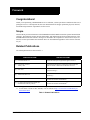
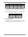
Related Publications
The related publications are listed in Table 1.
PUBLICATION NAME
PUBLICATION NAME
[1] ICD-GPS-200 Rev. B
NAVSTAR GPS Space Segment/Navigation Interface a
[2] RTCM-104 version 2.1
January 1994
Recommended Standards for Differential NAVSTAR GPS
Radio Technical Commission for Maritime Services a
[3] SAE J1211
SAE Recommended Environmental Practices for Electronic
Equipment Design a
[4] NMEA-0183 Rev 2.20
National Marine Electronics Association Standard for
Interfacing a
[5] STARVIEW User Manual
NovAtel Part Number OM-20000081 b
[6] L1 GPS Firmware Reference Manual (for
SUPERSTAR II-based products)
NovAtel Part Number OM-20000086 b
a. See Appendix D, Standards/References on Page 62 for contact information.
b. For the latest versions of these manuals, visit our website at http://www.novatel.com/Products/productmanuals.html.
Table 1: Related Publications
SUPERSTAR II User Manual Rev 3
13
Chapter 1
Introduction
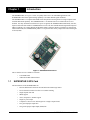
The SUPERSTAR II, see Figure 1 below, is a quality GPS receiver for embedded applications. The
SUPERSTAR II has robust signal tracking capability even under difficult signal conditions.
The SUPERSTAR II is a complete GPS OEM sensor that provides 3D navigation on a single compact board
with full differential capability. The SUPERSTAR II is a 12-channel GPS receiver that tracks all in-view
satellites. It is fully autonomous such that once power is applied, the SUPERSTAR II automatically searches,
acquires and tracks GPS satellites. SUPERSTAR II receivers also have Satellite Based Augmentation System
(SBAS) capability, for example WAAS and EGNOS. When a sufficient number of satellites are tracked with
valid measurements, the SUPERSTAR II produces a 3-D position and velocity output with an associated figure
of merit (FOM).
Figure 1: SUPERSTAR II Receiver
This L1 GPS receiver is available in 2 formats:
1.1
•
as an OEM board
•
within the FlexPak-SSII enclosure
SUPERSTAR II GPS Card
The main features of the SUPERSTAR II are:
14
•
Decodes differential corrections encoded in the RTCM message format
•
Twelve channel correlator for all-in-view satellite tracking
•
Single chip RF front end
•
SBAS support
•
Active, and passive, antenna support
•
Single 5V power input
•
Complete L1 GPS receiver and navigator on a single compact board
•
Two general purpose input lines
•
One general purpose input/output (GPIO) line
SUPERSTAR II User Manual Rev 3
Introduction
Chapter 1
•
Operating temperature range of -30°C to +75°C
•
1PPS output aligned on GPS Time + 200 ns
•
1Hz measurement output aligned on GPS Time
•
Support for 62 predefined datums
•
Field-upgradeable firmware (stored in Flash memory) through the TTL serial port
•
Code and Carrier Phase tracking of L1 GPS frequency for increased accuracy
•
Retention of satellite almanac and ephemeris data in non-volatile memory for rapid time-to-firstfix (TTFF) after power interruption
•
Very fast signal re-acquisition when signal masking (obstruction or vehicle attitude) occurs
•
Allows for warm start
•
1 Hz Position, Velocity and Time (PVT) output
Available Model Features1:
1.2
•
1 or 10 Hz carrier phase measurements (Message ID# 23, Measurement Block Data only works
with these models)
•
Precise timing
•
5 Hz PVT output
•
RTCM DGPS Base
FlexPak-SSII
The FlexPak-SSII, see Figure 2, is a hardware interface between your equipment and the SUPERSTAR II GPS
card. The Development Kit is an equipment set permitting easy evaluation of the receiver and includes the
SUPERSTAR II GPS card in a FlexPak-SSII enclosure. It provides single-frequency positioning with two
COM ports. A full description of this Development Kit and technical specifications of the FlexPak-SSII are
provided in Appendix B, FlexPak-SSII Specifications, starting on Page 49.
Figure 2: FlexPak-SSII Enclosure
The FlexPak-SSII offers the following features:
1.
•
A shock and dust resistant enclosure
•
Waterproof to IEC 60529 standards IPX4 and IPX7
Refer to Appendix A of the L1 GPS Firmware Reference Manual for models and their capabilities.
SUPERSTAR II User Manual Rev 3
15
Chapter 1
Introduction
•
Low power consumption
•
Two RS-232 serial ports
•
PPS output
•
Configurable mark inputs
•
Indicators for position, communication status and power
If you purchased a SUPERSTAR II Development Kit, the following is also provided with your FlexPak-SSII:
16
•
1 Deutsch to DB-9 serial cable
•
1 Deutsch to automobile power connector cable
•
1 AC/DC adaptor
•
1 +12 dB active GPS antenna with magnetic mount and integrated RF cable (6 m)
•
1 CD containing:
•
An installation program for NovAtel’s GPS L1 graphical user interface software,
StarView
•
Product documentation, including user manuals
SUPERSTAR II User Manual Rev 3
Chapter 2
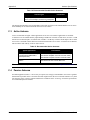
2.1
Receiver Specifications
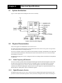
System Architecture
Figure 3 below depicts the block diagram of the receiver assembly.
Figure 3: Receiver Block Diagram
2.2
Physical Characteristics
This section applies to the OEM board version of the receiver.
For details on the physical characteristics of the FlexPak-SSII version of the receiver, please see Appendix B,
FlexPak-SSII Specifications, starting on Page 49.
The receiver assembly consists of one printed circuit board (PCB) containing a shielded RF section, digital and
I/O sections located on both sides of the PCB, and a surface mount connector. The receiver does not require
heat-sinking to a metal case.
Mechanical packaging of the receiver is designed to allow for mounting within various different configurations
of OEM units.
2.2.1
Radio Frequency (RF) Section
The receiver obtains a partially filtered and amplified GPS signal from the antenna through the coaxial cable.
The RF section performs the translation from the incoming RF signal to an IF signal usable by the digital
section. It also supplies power to the active antenna’s LNA through the coaxial cable while maintaining
isolation between the DC and RF paths. The RF section can reject a high level of potential interference (e.g.,
MSAT, Inmarsat, cellular phone, and TV sub-harmonic signals).
2.2.2
Digital Electronics Section
The digital section of the receiver, receives a down-converted, amplified GPS signal which it digitizes and
processes to obtain a GPS solution (position, velocity and time). The digital section consists of an analog-to-
SUPERSTAR II User Manual Rev 3
17
Chapter 2
Receiver Specifications
digital converter, a 16-bit system processor, memory, control and configuration logic, signal processing
circuitry, serial peripheral devices, and supporting circuitry.
The digital section performs the translations and calculations necessary to convert the IF analog signals into
usable position and status information. It also handles all I/O functions, including the auxiliary strobe signals,
which are described in detail in Section 3.4, Connectors and Connector Pins Assignment starting on Page 22.
For input and output levels please see Appendix A, Technical Specifications, starting on Page 44.
2.3
Enclosure and Wiring Harness
An enclosure is necessary to protect the GPSCard from environmental exposure and RF interference. If a
FlexPak-SSII is not being used as the enclosure, a wiring harness is also required to provide an interface to the
SUPERSTAR II’s antenna and power inputs as well as data and status signals.
2.4
GPS Antenna
The purpose of the GPS antenna is to convert the electromagnetic waves transmitted by the GPS satellites into
RF signals. An active or passive GPS antenna may be used in the operation of the receiver. NovAtel’s active
antennas are recommended.
2.4.1
Optional LNA Power Supply
Power for the antenna LNA is normally supplied by RF cable to J2, see also Section 3.4.3, RF Connector (J2)
starting on Page 23. However, if a different type of antenna is required that is incompatible with this supply,
connect an external power source to the receiver.
External LNA power is not possible with a FlexPak-SSII receiver.
2.5
Principal Power Supply
A single external power supply capable of delivering 5 V is necessary to operate the receiver. See Appendix A,
Technical Specifications, starting on Page 44 for details.
CAUTION: If the voltage supplied is below the minimum specification, the receiver will suspend
operation. If the voltage supplied is above the maximum specification, the receiver may
be permanently damaged, voiding your warranty.
2.6
Data Communications Equipment
A PC or other data communications equipment is necessary to communicate with the receiver and, if desired, to
store data generated by the receiver.
18
SUPERSTAR II User Manual Rev 3
Chapter 3
Installation
This section covers the installation of the receiver.
NovAtel’s StarView graphical user interface software running on a PC allows you to control the receiver and to
display its outputs. See Section B.3, StarView Software Installation starting on Page 55 for its installation
instructions. Details on the StarView program are provided in Reference [5] on Page 13.
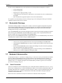
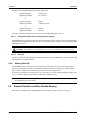
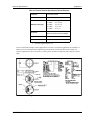
The SUPERSTAR II is an OEM product designed for flexibility of integration and configuration. You are free
to select an appropriate data and signal interface, power supply system and mounting structure. This allows you
to custom-design your own GPS-based positioning system around the SUPERSTAR II.
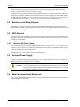
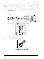
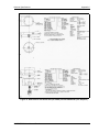
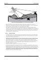
A typical system configuration is shown in Figure 4:
1
2
3
6
4
5
7
Figure 4: Typical System Configuration
Reference
Description
1
J2 to user-supplied GPS antenna
2
J2
3
User-supplied enclosure
4
User-supplied power, data and signal connector to J1
5
User-supplied interface
6
J1
7
COM1, COM2 and power connectors
SUPERSTAR II User Manual Rev 3
19
Chapter 3
Installation
In order for the SUPERSTAR II to perform optimally, the following additional equipment is required:
•
NovAtel GPS antenna
•
NovAtel coaxial cable
•
Regulated power supply providing +5 VDC
•
A wiring harness to provide power (connected to J1) as an interface for power, communications
and signals
•
Data communication equipment capable of TTL serial communications
See Appendix B, FlexPak-SSII Specifications, starting on Page 49 for a description of the type of enclosure
equipment required for the receiver to operate.
3.1
Electrostatic Discharge
Electrostatic discharge (ESD) is a leading cause of failure of electronic equipment components and printed
circuit boards containing ESD-sensitive devices and components. It is imperative that ESD precautions be
followed when handling or installing the SUPERSTAR II printed circuit board. See also the electrostatic
discharge notice on Page 10 of this manual.
Leave the SUPERSTAR II in its anti-static packaging when not connected in its normal operating environment.
When removing the SUPERSTAR II from the ESD-protective plastic, follow accepted standard anti-static
practices. Failure to do so may cause damage to the SUPERSTAR II.
When you remove the SUPERSTAR II from the original packing box, it is recommended that you save the box
and ESD protective plastic for future storage or shipment purposes.
REMEMBER!
3.2
•
Always wear a properly grounded anti-static wrist strap when handling the SUPERSTAR II.
•
Always hold the SUPERSTAR II by its corners or edges, and avoid direct contact with any of the
components.
•
Do not let the SUPERSTAR II come in contact with clothing at any time because the grounding
strap cannot dissipate static charges from fabrics.
•
Failure to follow accepted ESD handling practices could cause damage to the SUPERSTAR II.
•
Warranty may be voided if equipment is damaged by ESD.
Equipment Interconnection
As mentioned in Chapter 1, Introduction, starting on Page 14, the receiver can be provided either as an OEM
board, or within a FlexPak-SSII enclosure. The interconnection of the OEM board format is guided by its
physical and electrical specifications as detailed in Section 3.4, Connectors and Connector Pins Assignment
starting on Page 22. A complete description of the FlexPak-SSII is provided in Appendix B, FlexPak-SSII
Specifications, starting on Page 49.
3.2.1
Serial Connection
The receiver includes two serial communication ports. COM1 and COM2 are detailed in Section 3.4.2, Serial
Data Interface starting on Page 23. Serial communication with the receiver must be performed on COM1. The
maximum data transfer rate is 19200 bps. The other serial port, COM2, is used for a differential link, and its
minimal data transfer rate is 9600 bps. Communication with COM1 and COM2 is through two Deutsch
connectors on the FlexPak-SSII.
Please refer to the L1 GPS Firmware Reference Manual for a discussion on the I/O protocol.
20
SUPERSTAR II User Manual Rev 3
Installation
3.2.2
Chapter 3
Power Connection
The input range for a SUPERSTAR II card is either 3.3 VDC or 5 VDC depending on your model. The input
range required for the FlexPak-SSII is +6 to +18 VDC.
3.3
Installation Considerations
The FlexPak receiver is waterproof. The SUPERSTAR II bare card must be mounted in a dry location. Locate
your receiver where it is convenient for cables to run to the power source, display device, and antenna. Form
drip loops in the cables to prevent moisture from running down the cables and into the receiver.
Mount the receiver several feet away from radio transmission equipment.
3.3.1
Antenna Location
Many GPS reception problems can be reduced, to some degree, by careful antenna site selection. Of primary
importance is to place the antenna so that unobstructed line-of-sight reception is possible from horizon to
horizon and at all bearings and elevation angles from the antenna. This is, of course, the ideal situation, which
may not be possible under actual operating conditions.
1. Try to place the antenna as far as possible from obvious reflective objects, especially reflective
objects that are above the antenna’s radiation pattern horizon. Close-in reflections cause strong
multipath signals. For a detailed discussion on multipath and site selection, see Section G.4,
Multipath starting on Page 71.
2. Care should also be taken to avoid coiling the antenna cable around the mounting base and
pinching the antenna cable in window or door jambs.
By default, the SUPERSTAR II uses satellites above 4.5 degrees elevation. The mask angle can be set to use a
different cut-off, as low as zero degrees (all in view), using Message ID# 81, Set Mask Angle (refer to the L1
GPS Firmware Reference Manual for more message details).
3.3.2
Base Station Location
Your receiver must be a BASE model to act as a base station. A list of models is in Appendix A of the L1
GPS Firmware Reference Manual and in our Price List available from the Sales side menu of our website
at www.novatel.com.
1. The base station must be located on a site that is above all obscuring elements on the surrounding
terrain in order to have all satellites above the horizon visible at the base station’s antenna. The
intent is to have all satellites that are visible at the roving unit’s antenna to be visible at the base
station as well.
2. Multipath interference must be minimized as much as possible. Multipath is defined as the
interaction of the GPS satellite signal and its reflections. This causes errors mainly on the GPS
code, and less so on the GPS carrier. Even though the receiver uses carrier phase measurements, it
can revert to code differential GPS operation if carrier phase differential GPS cannot be
performed. Hence, the base station’s antenna must be far from any reflecting elements.
3. The position of the base station’s antenna must be surveyed using appropriate surveying
equipment. This position must then be programmed in the base station using Message ID# 80, Set
User’s Position/Operating Mode (refer to the L1 GPS Firmware Reference Manual). Any error in
the base station’s position will be reflected in the roving unit’s computed position.
SUPERSTAR II User Manual Rev 3
21
Chapter 3
3.3.3
Installation
Data Link
The data link for differential operation must operate at a minimal rate of 9600 bps.
3.3.4
Base Station and Rover Units Separation
The operational range of carrier-phase differential measurements is limited to about 20 km, after which
significant accuracy degradation can occur. If your application requires greater separations, your own base
station network must be established.
3.4
Connectors and Connector Pins Assignment
The receiver has two standard connectors.
•
•
J1 is a 20-pin connector for general input/output interfaces and power input
J2 is a MCX type RF connector.
The minimum number of connections on J1 required for the system to operate is shown in Table 2.
Table 2: Minimum J1 Connections
Signal Name
J1 Pin #
Description
VCC
2
Primary power (3.3V or 5.0V -0.5 V/+0.25 V)
GND
10, 13, 16 & 18
Ground
TX_No_1
11
Serial port Tx #1
RX_No_1
12
Serial port Rx #1
If DGPS corrections are required for the application, the SUPERSTAR II can receive them on COM2:
Signal Name
RX_No_2
J1 Pin #
15
Description
Serial port Rx #2
If an active antenna is used:
Signal Name
PREAMP
J1 Pin #
1
Description
Power for active antenna (40 mA max)
CAUTION: You should use a current-limiting power source. The maximum current is 40 mA.
See Appendix A, Technical Specifications, starting on Page 44 for more details.
3.4.1
J1 Interface and Power Connector
The SUPERSTAR II connector is a 2mm straight 2x10 pin header:
Suggested supplier:
On-Board connector:
22
Samtec
TMM-110-03-T-D.
SUPERSTAR II User Manual Rev 3
Installation
Chapter 3
Interface between SUPERSTAR II and customer application:
Suggested 2 inch ribbon cable:
TCSD-10-D-2.00-01-N
or
Suggested 12 inch ribbon cable with only one connector installed: TCSD-10-S-12.0-01-N
Suggested mating connector:
TCSD-10-01-N
or
PCB mounted connector:
SQT-110-01-L-D1
Connector specifications can be obtained from Samtec or other equivalent manufacturer.
3.4.2
Serial Data Interface
The receiver includes two COM ports (COM1 and COM2). Both COM ports operate independently with data
transfer rates adjustable from 300 to 19200 bps.
COM1 supports data input (for receiver configuration and control) and output (for example, navigation results
and receiver status). COM2 only supports data output if your SUPERSTAR II is a BASE model. This model
also supports data input (roving unit mode) or output (optional base station mode) for differential correction
data adhering to Reference [2] on Page 13.
Your receiver must be a BASE model to act as a base station. A list of models is in Appendix A of the L1
GPS Firmware Reference Manual and in our Price List available from the Sales side menu of our website
at www.novatel.com.
COM1 and COM2 support communication using the binary protocol. Through specific binary messages, the
ports are re-configurable to communicate with NovAtel’s PC-based user-interface StarView software (for
extensive monitoring of SV tracking, measurements and navigation status).
The default data transfer rate is 9600 bps but can be reconfigured (refer to Message ID# 110, Configure COM1
Port Mode in the L1 GPS Firmware Reference Manual). The new configuration is stored in NVM. If no default
message list has been stored in NVM, the receiver will output Message ID# 20, Navigation Data (refer to the
L1 GPS Firmware Reference Manual) at a rate of once per second after each power up.
COM1 can be used for S/W reprogramming (please see Appendix F, Updating Receiver Firmware, starting on
Page 64).
See also Section A.2.3 on Page 48 for the electrical characteristics and the Input/Output Message rows on Page
45 for COM port details.
The default data transfer rate is 9600 bps unless your receiver model has Carrier Phase Output (CP)
capability in which case it may be 19200. A list of models is in Appendix A of the L1 GPS Firmware
Reference Manual and in our Price List available from the Sales side menu of our website at
www.novatel.com.
3.4.3
RF Connector (J2)
The standard RF connector is a straight MCX jack connector.
Suggested supplier:
On-Board connector:
Johnson Comp
133-3701-211
1. 0.340" long standoffs will be required
SUPERSTAR II User Manual Rev 3
23
Chapter 3
Installation
Interface between SUPERSTAR II and customer application:
Suggested Supplier:
Supplier part number:
Omni Spectra
5831-5001-10
or
Suggested Supplier:
Supplier part number:
Suhner
11MCX-50-2-10C
or
Suggested Supplier:
Supplier part number:
Radiall
R113082.
The center conductor provides power for an active antenna (PREAMP signal from J1-1).
3.4.3.1
Preamplifier Power Pass-Through (Antenna Supply)
The PREAMP signal is available on the I/O connector for the host to provide power to the antenna preamplifier
through the center conductor of the RF cable J2. The maximum operating voltage for an active antenna supply
(PREAMP) is 12 Volts.
CAUTION: You should use a current-limiting power source. The maximum current on J2 is 40 mA.
3.4.3.2
RF Input
The receiver will receive the GPS signal from the antenna amplifier on the J2 RF input connector. The RF input
port impedance is 50 Ohms nominal.
3.4.4
Memory Back-Up
The SUPERSTAR II has a supercap device allowing a warm start, where the receiver has an approximate
position, an approximate time and a valid almanac, without the need of an external power supply during a
power-off state. VBATT is an external back-up source for the time keeping circuit.
A warm start is available for 1 week typically (25°C) and 3 days over a more extreme temperature range (-30 to
+75°C). Therefore, VBATT can be used to extend the time retention period.
An external series diode will be required between J1 and the external power source to prevent the supercap
from discharging into your circuitry.
3.5
Protocol Selection and Non Volatile Memory
Discrete IOs are available with a SUPERSTAR II card. A summary is shown in Table 3 on Page 25.
24
SUPERSTAR II User Manual Rev 3
Installation
Chapter 3
Table 3: Use of Discretes
Discrete Name
FlexPak Equivalent Name
Use
Direction
GPIO2
IO1
Navigator
IN/OUT
GPIO3
IO2
SP
IN/OUT
GPIO5
IP1
GPS Data
IN/OUT
GPIO6
IP2
NVM Control
IN/OUT
GPIO7
IP3
Protocol Select
IN/OUT
If you use NMEA, the SUPERSTAR II offers you the option of setting the I/O operating mode to NMEA
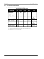
through discrete input levels. Disc_IP2 and Disc_IP3 have the following functions:
Table 4: Discretes IP2 and IP3 functions
Disc_IP3
(Protocol Select)
Disc_IP2
(NVM Control)
Result
OPEN - HI
OPEN - HI
Configuration stored in NVM or Default ROM Configuration if no valid NVM elements
OPEN - HI
GND
Protocol on Port #1: Binary
Baud Rate on Port #1: 9600
Other elements: Default ROM Configuration
GND
OPEN - HI
Protocol on Port #1: NMEA
Baud Rate on Port #1: 4800
Other elements: Default ROM Configuration if no valid
NVM elements
GND
GND
Protocol on Port #1: NMEA
Baud Rate on Port #1: 4800
Other elements: Default ROM Configuration
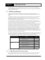
Discrete inputs are also shown in byte 26 of Message ID# 49, Receiver Status Data, refer to the L1 GPS
Reference Manual.
SUPERSTAR II User Manual Rev 3
25
Chapter 3
3.5.1
Installation
Non Volatile Memory
The receiver stores different types of information used to accelerate the TTFF and to configure the I/O in
NVM. See Table 5 below for a partial list of the data stored in NVM.
Table 5: Non-Volatile Memory Data
Parameter
3.6
Notes
ALMANAC
The most recent almanac
LAST POSITION
Position in NVM is updated at different rates depending on the
application. The last known position is always kept in battery backup SRAM.
DGPS CONFIGURATION
Differential GPS configuration
TTL CONFIGURATION
Contains the following configuration information:
1. Mode of operation
4. Time Alignment Mode State
2. Baud Rate: 300 to 19200
5. Mask Angle
3. Default Binary message list
6. Datum
Default Configuration
Below is the SUPERSTAR II’s default configuration with no valid NVM elements:
Protocol on port #1:
Baud Rate on port #1:
Protocol on port #2:
Baud Rate on port #2:
DGPS Correction Timeout:
Default Message List:
Binary:
NMEA:
Time Align Mode:
1.
Binary
9600
RTCM-104
9600
45 seconds
Navigation Status User Coordinates (Message ID# 20) @ 1Hz
GGA @ 1Hz
ON
The data contained in NVM is always used if the DISC_IP2 is left unconnected or tied to HI logic.
2.
The default data transfer rate is 9600 bps unless your receiver model has Carrier Phase Output (CP)
capability in which case it may be 19200. A list of models is in Appendix A of the L1 GPS Firmware
Reference Manual and in our Price List available from the Sales side menu of our website at
www.novatel.com.
3.
If DISC_IP2 is tied to LO logic, the default ROM configuration will be used and the following
parameters will not be read from NVM:
Position
Almanac
Time
UTC Correction and IONO Parameters
TCXO Parameters
26
SUPERSTAR II User Manual Rev 3
Installation
3.7
Chapter 3
Installation Overview
Once you have selected the appropriate equipment, complete the following steps to set up and begin using your
NovAtel SUPERSTAR II receiver.
1.
If your receiver has been provided as a GPS card without an enclosure, install the card in an enclosure to
reduce environmental exposure, RF interference and vibration effects.
2.
Pre-wire your I/O harness 20-pin connector for power and communications and connect them to the J1
connector on the SUPERSTAR II. See also Section 3.4, Connectors and Connector Pins Assignment
starting on Page 22.
3.
4.
Mount the GPS antenna to a secure, stable structure, as described in Section 3.3.1 on Page 21.
Connect the GPS antenna to the receiver using an antenna RF cable, using the information given in
Section 3.4.3.1, Preamplifier Power Pass-Through (Antenna Supply), and Section 3.4.3.2, RF Input
starting on Page 24.
Apply power to the receiver, as described in Section 3.2.2, Power Connection starting on Page 21.
Connect the receiver to a PC or other data communications equipment by following the information given
in Section 3.2.1, Serial Connection starting on Page 20 and 3.4.2, Serial Data Interface on Page 23.
5.
6.
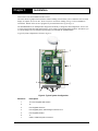
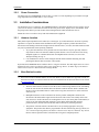
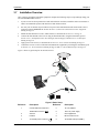
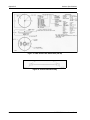
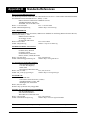
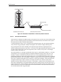
Figure 5 shows a typical setup for an enclosed receiver.
1
2
3
9
4
8
7
5
6
Figure 5: Basic Setup
Reference
1
Description
Reference
Description
Coaxial cable from antenna to
5
12 V DC Adaptor
FlexPak RF connector (
6
120 V AC power supply
)
2
Antenna
7
User-supplied PC
3
FlexPak
8
DB-9 connector to PC
4
To FlexPak power connector (
9
To FlexPak COM port (COM1)
SUPERSTAR II User Manual Rev 3
)
27
Chapter 4
Operation
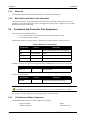
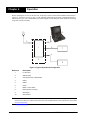
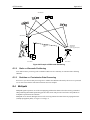
Before operating the receiver for the first time, ensure that you have followed the installation instructions in
Chapter 3, Installation starting on Page 19. The following instructions are based on a configuration such as
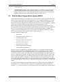
that shown in Figure 6. It is assumed that a personal computer is used during the initial operation and testing
for greater ease and versatility.
10
3
4
9
1
5
7
6
2
8
Figure 6: Typical Operational Configuration
Reference
Description
1
L1 GPS card
2
OEM housing
3
Command source or base station
4
COM1
5
COM2
6
Power
7
Radio or rover station
8
External power source(s)
9
GPS signal
10
GPS antenna
Your receiver must be a BASE model to act as a base station. A list of models is in Appendix A of the L1
GPS Firmware Reference Manual and in our Price List available from the Sales side menu of our website
at www.novatel.com.
28
SUPERSTAR II User Manual Rev 3
Operation
4.1
Chapter 4
Communications with the Receiver
Communication with the receiver is straightforward, and consists of issuing commands through the
communication ports from an external serial communications device. This could be either a terminal or an
IBM-compatible PC that is directly connected to the COM1 serial port of the receiver using a straight serial
cable. If you are using a TTL communications device such as a radio modem, connect it to the receiver’s
COM2 port by means of a radio serial cable. For information about input and output messages that are useful
for basic operation of the receiver, refer to the L1 GPS Firmware Reference Manual. See also the StarView
examples in Section 4.2, Getting Started starting on Page 29.
4.1.1
Serial Port Default Settings
The receiver communicates with your PC or terminal through a serial port. For communication to occur, both
the receiver and the operator interface have to be configured properly. The receiver’s COM1 and COM2 default
port settings are as follows:
•
9600 bps, no parity, 8 data bits, 1 stop bit, no handshaking, echo off
Changing the default baud setting requires using Message ID# 110, Configure COM1 Port Mode which is
described in the L1 GPS Firmware Reference Manual. It is recommended that you become thoroughly familiar
with the input and output messages detailed in the above reference manual to ensure maximum utilization of
the receiver’s capabilities.
The default data transfer rate is 9600 bps unless your receiver model has Carrier Phase Output (CP)
capability in which case it may be 19200. A list of models is in Appendix A of the L1 GPS Firmware
Reference Manual and in our Price List available from the Sales side menu of our website at
www.novatel.com.
The data transfer rate you choose will determine how fast information is transmitted. Take for example a
message whose byte count is 96. The default port settings will allow 10 bits/byte. It will therefore take 960 bits
per message. To get 10 messages per second then will require 9600 bps. Please also remember that even if you
set the bps to 9600 the actual data transfer rate will be less and depends on the number of satellites being
tracked, filters in use, and idle time. It is therefore suggested that you leave yourself a margin when choosing a
data rate.
CAUTION:
4.2
Although the receiver can operate at data transfer rates as low as 300 bps, this is not
desirable. For example, if several data messages are active (that is, a significant amount of
information needs to be transmitted every second) but the bit rate is set too low, data
overflows the serial port buffers, causes an error condition in the receiver status and results
in lost data.
Getting Started
Included with your receiver is NovAtel’s StarView program. StarView is a Windows-based graphical user
interface which allows you to access the receiver's many features without struggling with communications
protocol or writing special software. The information is displayed in windows accessed from the Window
menu. For example, to show details of the GPS satellites being tracked, select Satellites | Status from the
Window menu. Select Navigation | LLH Solution from the Window menu to display the position of the receiver
in LLH (latitude, longitude and height) coordinates.
The receiver is in Navigation mode whenever sufficient satellite information and measurement data is available
to produce a GPS fix. When the receiver has a valid position, the Nav Mode field in StarView’s LLH Solution,
SUPERSTAR II User Manual Rev 3
29
Chapter 4
Operation
or XYZ Solution, window shows Nav 3-D, Diff. 3-D or Dead Reckoning. If it shows Initialized there is no valid
position yet.
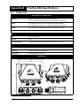
The FlexPak-SSII uses a comprehensive message interface. Input messages can be sent to the receiver using the
Xmit Msg menu in StarView.
The following information is important when selecting commands:
1. Message requests are only output to the receiver in binary format. They may however be viewed in
ASCII format through StarView windows.
2. You can send a message request using one shot (normal mode) or continuous (special mode) by
selecting Xmit Msg | General Message Request in StarView.
3. There is an option in StarView to save all messages transmitted by the receiver into a file. Select
File/Port | Save Data after you have finished selecting messages in Step #2 above.
The L1 GPS Firmware Reference Manual provides the available messages and parameters that the
SUPERSTAR II uses. See also Section B.3, StarView Software Installation starting on Page 55 and refer to the
StarView User Manual for more information on the StarView program.
The receiver’s software resides in read-only memory. As such, the unit “self-boots” when turned on and
undergoes a complete self-test, see Section 4.5.2, Operational States starting on Page 31. If a persistent error
develops, please contact your local NovAtel dealer first. If the problem is still unresolved, please contact
NovAtel directly through any of the methods in the Customer Service section at the beginning of this manual
on Page 9.
4.2.1
Power-Up Information
At power up, the receiver sends two categories of factory information data to COM1at 9600 bps. The
categories of information, Boot and Operational information, can be displayed on a dummy terminal.
4.2.2
Boot Information
The Boot information contains the following factory data:
SUPERSTAR II
V4
G: XXXXXXXXXX
169-613914-007
: Boot S/W Part Number
D0
PCPB: XXXXXXXXXX
GO
: Go in Operational Mode
4.2.3
Operational Information
The Operational information contains both the factory and the current operating mode information. The current
operating mode baud rate is output twice. This is useful when the operating baud rate is not 9600.
Example:
<Part Nb:169-614110-XXX1, CB=0x0000003F2 SHP
Go to Binary @ 19200 baud
In Binary @ 19200 baud3
I>3
1. Operational S/W Part Number
2. Power-up BIT result.
3. Line transmitted at the Configured Baud Rate
30
SUPERSTAR II User Manual Rev 3
Operation
4.3
Chapter 4
Data Requests
Data may be requested for output by the receiver for display or logging purposes. The list of data request
commands and data messages is detailed in the L1 GPS Firmware Reference Manual.
4.4
Configurable Parameters
Several parameters of the receiver and the base station are configurable and therefore, you must define them
prior to operation.
Your receiver must be a BASE model to act as a base station. A list of models is in Appendix A of the L1
GPS Firmware Reference Manual and in our Price List available from the Sales side menu of our website
at www.novatel.com.
4.4.1
Mask Angle
The mask angle is defined as the minimum satellite elevation angle (in degrees) above which any given satellite
must be in order for it to be used in the GPS position solution. Low satellites usually do not yield accurate
measurements due to weak signal reception and possible multipath. Typical mask angle values range from 5°10°, depending on the receiver’s location. This value is programmable using command Message ID# 81, Set
Mask Angle.
4.4.2
GPS Antenna Position
For the base station, it is imperative to fix the position. This can be done using either the X-Y-Z coordinates in
meters within the WGS-84 reference frame, or latitude and longitude in degrees and height in meters (LLH
coordinates) by selecting Tool Setting | Set Operating Mode in the main menu of StarView.
You can also set the X-Y-Z coordinates using Message ID# 80, Set User’s Position/Operating Mode.
4.5
Receiver States
4.5.1
Non-Operational State
The receiver’s non-operational state is OFF mode. In OFF mode, only the data contained in the NVM is
retained for use when power is re-applied. See Section 3.5, Protocol Selection and Non Volatile Memory
starting on Page 24 for details on retained data. A supercap allows the SUPERSTAR II to maintain data and
time during OFF mode for a period of 3 days to a week.
4.5.2
Operational States
The receiver has 6 operating modes:
•
Self-Test
•
Initialization
•
Acquisition
•
Navigation
•
Dead-Reckoning
•
Fault
SUPERSTAR II User Manual Rev 3
31
Chapter 4
Operation
The receiver switches between modes automatically. The receiver reports on its host port the current operating
and navigation modes.
1. Self-Test Mode
The receiver enters Self-Test mode upon request from an external source (please refer to Message
ID# 51, Initiated BIT in the L1 GPS Firmware Reference Manual). The time duration spent in the
Self-Test mode is no more than 15 seconds. On self-test completion, the receiver reports the BIT
results on its host port through Message ID# 51. Self-Test mode exits to either Initialization or
Fault mode.
2. Initialization Mode
Upon power-up, the receiver enters Initialization mode. During this mode hardware is initialized
prior to Acquisition mode entry. The Initialization mode is also initiated upon completion of the
Self-Test mode, but always exits to the Acquisition mode.
When the receiver is in OFF mode, it will retrieve data only from NVM (cold start) or from both
NVM and SRAM (warm start). Integrity checking is done on all data retrieved from the nonoperating state. See also Section 4.5.1, Non-Operational State above.
During initialization, the receiver retrieves the last received valid almanac data and last user
position from NVM, the current time from the low-power time source, and predicts which
satellites are currently visible. This list of visible satellites is then used in Acquisition mode to
program the 12 parallel correlator channels.
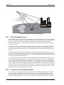
3. Acquisition Mode
The receiver is in Acquisition mode when insufficient satellite data is available to produce an
initial navigation solution. Acquisition mode is entered from Initialization, or Dead-Reckoning
mode, and exits to Navigation or Fault mode.
To acquire signals from the GPS satellites, the receiver uses:
•
Almanac data which describes the satellite orbits
•
Time, which in conjunction with almanac data is used to estimate the present
position of satellites in their orbits
•
The approximate location of the receiver so a prediction can be made as to which
satellites are visible
The receiver then collects ephemeris data by decoding the satellite down-link data message. After
each satellite in view is acquired, its measurement data set is produced. When a sufficient number
of satellites are being tracked, position, velocity and time can be computed and Navigation mode
entered.
If the receiver cannot perform an acquisition due to an absence of valid almanac data or user
position and/or time, it initiates a "Search the Sky" acquisition. The receiver attempts to acquire all
satellites in the GPS constellation. Once a satellite has been acquired, ephemeris data is decoded
from the satellite down-link message. After sufficient satellites have been acquired, the receiver
enters Navigation mode. In "Search the Sky", the TTFF is typically less than 3 minutes.
4. Navigation Mode
The receiver is in Navigation mode whenever sufficient satellite information and measurement
data is available to produce a GPS fix. Navigation mode is entered from Acquisition or DeadReckoning mode, and exits to Dead-Reckoning or Fault mode.
In Navigation mode, a receiver configured as a roving unit operates in 2 sub-modes: Differential
and Stand-Alone Nav. Sub-mode transition occurs automatically depending on satellite data
availability. A receiver which is configured as a base station unit will operate in Base Station Nav
32
SUPERSTAR II User Manual Rev 3
Operation
Chapter 4
mode only. The receiver reports its current navigation sub-mode on its host port.
Your receiver must be a BASE model to act as a base station. A list of models is in Appendix A of the L1
GPS Firmware Reference Manual and in our Price List available from the Sales side menu of our website
at www.novatel.com.
a. Differential (Roving Unit Only)
The receiver operates in Differential mode when data from at least 4 satellites with
adequate geometry and differential corrections and/or measurements exist to compute
position, velocity and time outputs. This is the preferred navigation mode. Differential
data is supplied to the receiver through the differential input port. Differential data can be
received only on the COM2 serial data port.
b. Stand-Alone Nav (Roving Unit Only)
The receiver operates in Stand-Alone Nav mode when it has data from at least 4 satellites
with adequate geometry, but no differential corrections or measurements, exist to
compute position, velocity and time outputs. This is the preferred navigation mode when
insufficient differential data is available to generate a differential GPS fix.
c. Base Station Nav (Base Station Unit Only)
The receiver operates in Base Station Nav mode once the time has been initialized and at
least 4 satellites with adequate geometry can be used for navigation purposes. Once in
this mode, only a change of configuration (rover mode requested) or a reset will cause the
unit to leave this navigation mode. In this mode, the unit will have the ability to transmit
the DGPS messages which are requested and allowed once its position is initialized. See
also Section 4.4, Configurable Parameters starting on Page 31 for position initialization
details.
5. Dead-Reckoning Mode
The receiver enters Dead-Reckoning mode when it cannot remain in Navigation mode. The speed
and direction is assumed to be constant to allow the receiver to provide an estimated position.
6. Fault Mode
The receiver enters Fault mode during the period of time in which the receiver outputs are affected
by one or more critical system faults. This mode supersedes all others and remains active until the
next power-down/power-up cycle. Fault mode is entered from any mode except Initialization.
4.6
Built-In Status Tests
The receiver performs self-tests and generates status information to provide an indication of the operational
readiness and to facilitate maintenance actions.
The built in test monitors system performance and status to ensure the receiver is operating within its
specifications. If an exceptional condition is detected, you are informed through one or more indicators. The
receiver status system is used to configure and monitor these indicators:
•
Message ID# 49, Receiver Status Data
•
Message ID# 51, Initiated BIT Result
•
Status LED on the FlexPak-SSII
Please refer to the L1 GPS Firmware Reference Manual for details on the Message IDs above. See also Section
4.5.2, Operational States starting on Page 31 and status LED information may be found in this manual on Page
50.
SUPERSTAR II User Manual Rev 3
33
Chapter 4
4.7
Operation
DATUM Support
The receiver has the ability to provide its position in one of the 62 predefined datums. The list of the supported
datum and details on Message ID# 88, Select/Define Datum to Use are provided in the L1 GPS Firmware
Reference Manual. The receiver can also support two user-defined datums. You must define them, prior to their
use, using Message ID# 88. Afterwards, the desired datum, whether it is user-defined or predefined, can be
selected using the above message.
34
SUPERSTAR II User Manual Rev 3
Chapter 5
Message Formats
The chapter discusses the industry-standard message formats that can be used with your SUPERSTAR II
receiver, including RTCM and NMEA. Refer to the L1 GPS Firmware Reference Manual for more information
on using these message formats.
5.1
RTCM-Format Messages
The Radio Technical Commission for Maritime Services (RTCM) was established to facilitate the
establishment of various radio navigation standards, which includes recommended GPS differential standard
formats.
The standards recommended by the Radio Technical Commission for Maritime Services Special Committee
104, Differential GPS Service (RTCM SC-104,Washington, D.C.), have been adopted by NovAtel for
implementation into the receiver. Because the receiver is capable of utilizing RTCM formats, it can easily be
integrated into positioning systems around the globe.
As it is beyond the scope of this manual to provide in-depth descriptions of the RTCM data formats, it is
recommended that anyone requiring explicit descriptions of such, should obtain a copy of the published RTCM
specifications. See Appendix D, Standards/References on Page 62 for reference information.
Message ID# 83, DGPS Configuration contains one or part of a RTCM message. The message type selected in
the Set DGPS Configuration message (Message ID# 83, bytes 9 to 16) is retransmitted through this message.
Message length is variable and a message can be transmitted up to once every 100 ms. A RTCM message
always starts as the first byte of a message and always ends as the last byte of a message. Thus, a RTCM
message can be output in one or many messages but a message block cannot contain more than one RTCM
message. The control byte is used to determine the start and the end of a RTCM message. The sequence
number of the control byte can be used to detect the loss of a message block on the transmitter side. It starts at
0 and increments by one for each consecutive message block (0,1,2,3,0,1,2,3,0,1,...). Refer also to the L1 GPS
Firmware Reference Manual for details on this message.
All receiver messages adhere to the structure recommended by RTCM SC-104. Thus, all RTCM messages are
composed of 30 bit words. Each word contains 24 data bits and 6 parity bits. All RTCM messages contain a 2word header followed by 0 to 31 data words for a maximum of 33 words (990 bits) per message.
Message Frame Header
Word 1
Word 2
Data
Bits
–
Message frame preamble for synchronization
8
–
Frame/message type ID
6
–
Base station ID
10
–
Parity
6
–
Modified z-count (time tag)
13
–
Sequence number
3
–
Length of message frame
5
–
Base health
3
–
Parity
6
The remainder of this section will provide further information concerning receiver RTCM data formats.
5.1.1
RTCM1 Differential GPS Corrections (Fixed)
This is the primary RTCM message used for pseudorange differential corrections. This message follows the
RTCM Standard Format for a Type 1 message. It contains the pseudorange differential correction data
SUPERSTAR II User Manual Rev 3
35
Chapter 5
Message Formats
computed by the base station generating this Type 1 message. The message is of variable length, depending on
the number of satellites visible and pseudoranges corrected by the base station. Satellite specific data begins at
word 3 of the message.
Type 1 messages contain the following information for each satellite in view at the base station:
•
•
•
•
Satellite ID
Pseudorange correction
Range-rate correction
Issue of Data (IOD)
When operating as a base station, the receiver’s position must be set using Message ID# 80, Set User’s
Position/Operating Mode. When operating as a rover station, the receiver COM port receiving the RTCM data
must be set to Rover mode using command Message ID# 80. Please refer to the L1 GPS Firmware Reference
Manual for more details on this input message.
5.1.2
RTCM2 Delta Differential GPS Corrections (Fixed)
Quite often a base station may have new ephemeris data before rover stations have collected the newer
ephemeris. The purpose of Type 2 messages is to act as a bridge between old and new ephemeris data. A base
station will transmit this Type 2 bridge data concurrently with Type 1's for a few minutes following receipt of a
new ephemeris. The rover station adds the Type 2 data (delta of old ephemeris minus new ephemeris) to the
Type 1 message data (new ephemeris) to calculate the correct pseudorange corrections (based on the old
ephemeris). Once the rover receiver has collected its own updated ephemeris, it will no longer utilize the Type
2 messages.
The GPS Card will accept and decode RTCM Standard Type 2 messages, when available and if required.
Type 2 messages are variable in length, depending on the number of satellites being tracked by the base station.
5.1.3
RTCM9 Partial Satellite Set Differential Corrections
RTCM Type 9 messages follow the same format as Type 1 messages. However, unlike a Type 1 message, Type
9 does not require a complete satellite set. This allows for much faster differential correction data updates to the
rover stations, thus improving performance and reducing latency.
Type 9 messages should give better performance with slow or noisy data links.
The base station transmitting the Type 9 corrections must be operating with a high-stability clock to
prevent degradation of navigation accuracy due to the unmodeled clock drift that can occur between Type
9 messages. For this reason, only receivers with an external oscillator can generate Type 9 messages.
SUPERSTAR II receivers can accept Type 9 messages.
NovAtel recommends a high-stability clock such as the PIEZO Model 2900082 whose 2-sample (Allan)
variance meets the following stability requirements:
3.24 x 10⁻²⁴ s2/s2 between 0.5 - 2.0 seconds, and
1.69 x 10⁻²² T s2/s2 between 2.0 - 100.0 seconds
An external clock, such as an OCXO, requires approximately 10 minutes to warm up and become fully
stabilized after power is applied; do not broadcast RTCM Type 9 corrections during this warm-up period.
36
SUPERSTAR II User Manual Rev 3
Message Formats
Chapter 5
Type 9 messages contain the following information for a group of three satellites in view at the base station:
•
•
•
•
•
•
5.2
Scale factor
User Differential Range Error
Satellite ID
Pseudorange correction
Range-rate correction
Issue of Data (IOD)
NMEA Format Data Messages
The NMEA log structures follow format standards as adopted by the National Marine Electronics Association.
The reference document used is "Standard For Interfacing Marine Electronic Devices NMEA 0183 Version
2.00". For further information, see Appendix D, Standards/References on Page 62. The following table contains
excerpts from Table 6 of the NMEA Standard which defines the variables for the NMEA messages. The actual
format for each parameter is indicated after its description.
Field Type
Symbol
Definition
Special Format Fields
Status
A
Single character field:
A = Yes, Data Valid, Warning Flag Clear
V = No, Data Invalid, Warning Flag Set
Latitude
llll.ll
Fixed/Variable length field:
degrees|minutes.decimal - 2 fixed digits of degrees, 2 fixed digits of minutes and
a variable number of digits for decimal-fraction of minutes. Leading zeros always
included for degrees and minutes to maintain fixed length. The decimal point and
associated decimal-fraction are optional if full resolution is not required.
Longitude
yyyyy.yy
Fixed/Variable length field:
degrees|minutes.decimal - 3 fixed digits of degrees, 2 fixed digits of minutes and
a variable number of digits for decimal-fraction of minutes. Leading zeros always
included for degrees and minutes to maintain fixed length. The decimal point and
associated decimal-fraction are optional if full resolution is not required
Time
hhmmss.ss
Fixed/Variable length field:
hours|minutes|seconds.decimal - 2 fixed digits of hours, 2 fixed digits of minutes,
2 fixed digits of seconds and variable number of digits for decimal-fraction of
seconds. Leading zeros always included for hours, minutes and seconds to
maintain fixed length. The decimal point and associated decimal-fraction are
optional if full resolution is not required.
Defined field
Some fields are specified to contain pre-defined constants, most often alpha
characters. Such a field is indicated in this standard by the presence of one or
more valid characters. Excluded from the list of allowable characters are the
following which are used to indicate field types within this standard:
"A", "a", "c", "hh", "hhmmss.ss", "llll.ll", "x", "yyyyy.yy"
Numeric Value Fields
Variable
numbers
x.x
Variable length integer or floating numeric field. Optional leading and trailing
zeros. The decimal point and associated decimal-fraction are optional if full
resolution is not required (example: 73.10 = 73.1 = 073.1 = 73)
Fixed HEX
hh___
Fixed length HEX numbers only, MSB on the left
Information Fields
Variable text
c--c
Variable length valid character field.
Fixed alpha
aa___
Fixed length field of uppercase or lowercase alpha characters
Fixed number
xx___
Fixed length field of numeric characters
Fixed text
cc___
Fixed length field of valid characters
1.
2.
3.
4.
5.
NOTES:
Spaces may only be used in variable text fields.
A negative sign "-" (HEX 2D) is the first character in a Field if the value is negative. The sign is omitted if value is positive.
All data fields are delimited by a comma (,).
Null fields are indicated by no data between two commas (,,). Null fields indicate invalid or no data available.
The NMEA Standard requires that message lengths be limited to 82 characters.
SUPERSTAR II User Manual Rev 3
37
Chapter 6
Positioning Modes of Operation
The following single frequency modes of operation are described further in this chapter:
• Single Point or Autonomous
• Satellite-Based Augmentation System (SBAS)
See Appendix G, GPS Overview on Page 67 for an overview of GPS positioning.
6.1
Single-Point or Autonomous
The NovAtel SUPERSTAR II receiver is capable of absolute single-point positioning accuracies of < 5 meters
CEP (GDOP < 2; no multipath).
The general level of accuracy available from single-point operation may be suitable for many types of
applications that do not require position accuracies of better than 5 m CEP. However, increasingly more and
more applications desire and require a much higher degree of accuracy and position confidence than is possible
with single-point pseudorange positioning. This is where differential GPS (DGPS) plays a dominant role in
higher accuracy real-time positioning systems, see also Section G.3, GPS Positioning on Page 69.
By averaging many GPS measurement epochs over several hours, it is possible to achieve a more accurate
absolute position.
The next section deals with the type of GPS system errors that can affect accuracy in single-point operation.
6.1.1
GPS System Errors
In general, GPS SPS C/A code single-point pseudorange positioning systems are capable of absolute position
accuracies of about 5 meters or less. This level of accuracy is really only an estimation, and may vary widely
depending on numerous GPS system biases, environmental conditions, as well as the GPS receiver design and
engineering quality.
There are numerous factors which influence the single-point position accuracies of any GPS C/A code
receiving system. As the following list will show, a receiver’s performance can vary widely when under the
influences of these combined system and environmental biases.
38
•
Ionospheric Group Delays – The earth’s ionospheric layers cause varying degrees of GPS signal
propagation delay. Ionization levels tend to be highest during daylight hours causing propagation
delay errors of up to 30 meters, whereas night time levels are much lower and may be as low as 6
meters.
•
Tropospheric Refraction Delays – The earth’s tropospheric layer causes GPS signal propagation
delays. The amount of delay is at the minimum (about three metres) for satellite signals arriving from
90 degrees above the horizon (overhead), and progressively increases as the angle above the horizon
is reduced to zero where delay errors may be as much as 50 metres at the horizon.
•
Ephemeris Errors – Some degree of error always exists between the broadcast ephemeris’ predicted
satellite position and the actual orbit position of the satellites. These errors will directly affect the
accuracy of the range measurement.
•
Satellite Clock Errors – Some degree of error also exists between the actual satellite clock time and
the clock time predicted by the broadcast data. This broadcast time error will cause some bias to the
pseudorange measurements.
•
Receiver Clock Errors – Receiver clock error is the time difference between GPS receiver time and
true GPS time. All GPS receivers have differing clock offsets from GPS time that vary from receiver
to receiver by an unknown amount depending on the oscillator type and quality (TCXO verses
SUPERSTAR II User Manual Rev 3
Positioning Modes of Operation
Chapter 6
OCXO, and so on).
•
6.2
Multipath Signal Reception – Multipath signal reception can potentially cause large pseudorange
and carrier phase measurement biases. Multipath conditions are very much a function of specific
antenna site location versus local geography and man-made structural influences. Severe multipath
conditions could skew range measurements by as much as 100 meters or more.
Satellite-Based Augmentation System (SBAS)
A Satellite-Based Augmentation System (SBAS) is a type of geo-stationary satellite system that improves the
accuracy, integrity, and availability of the basic GPS signals. Accuracy is enhanced through the use of wide
area corrections for GPS satellite orbits and ionospheric errors. Integrity is enhanced by the SBAS network
quickly detecting satellite signal errors and sending alerts to receivers to not use the failed satellite. Availability
is improved by providing an additional ranging signal to each SBAS geostationary satellite.
SBAS includes the Wide-Area Augmentation System (WAAS), the European Geo-Stationary Navigation
System (EGNOS), and the MTSAT Satellite-Based Augmentation System (MSAS). At the time of publication,
there are two WAAS satellites over the western Atlantic Ocean and the Pacific (PRN 122 and PRN 134
respectively) and one EGNOS satellite over the eastern Atlantic Ocean (PRN 120). SBAS data is available
from any of these satellites and more satellites will be available in the future.
The primary functions of SBAS include:
•
data collection
•
determining ionospheric corrections
•
determining satellite orbits
•
determining satellite clock corrections
•
determining satellite integrity
•
independent data verification
•
SBAS message broadcast and ranging
•
system operations & maintenance
As shown in Figure 7, The SBAS Concept, the SBAS is made up of a series of Reference Stations, Master
Stations, Ground Uplink Stations and Geostationary Satellites (GEOs). The Reference Stations, which are
geographically distributed, pick up GPS satellite data and route it to the Master Stations where wide area
corrections are generated. These corrections are sent to the Ground Uplink Stations which up-link them to the
GEOs for re-transmission on the GPS L1 frequency. These GEOs transmit signals which carry accuracy and
integrity messages, and which also provide additional ranging signals for added availability, continuity and
accuracy. These GEO signals are available over a wide area and can be received and processed by L1 GPS
receivers with appropriate firmware. GPS user receivers are thus able to receive SBAS data in-band and use not
only differential corrections, but also integrity, residual errors and ionospheric information for each monitored
satellite.
The signal broadcast through the SBAS GEOs to the SBAS users is designed to minimize modifications to
standard GPS receivers. As such, the GPS L1 frequency (1575.42 MHz) is used, together with GPS-type
modulation - e.g. a Coarse/Acquisition (C/A) pseudorandom (PRN) code. In addition, the code phase timing is
SUPERSTAR II User Manual Rev 3
39
Chapter 6
Positioning Modes of Operation
maintained close to GPS time to provide a ranging capability.
Geostationary
Satellite (GEO)
L1
GPS Satellite
Constellation
L1 & L2
L1 & C-band
Integrity data,
differential corrections,
and ranging control
GPS User
C-band
Reference Station
Reference Station
Reference Station
Ground Uplink
Station
Master Station
Integrity data,
differential corrections,
time control, and status
Figure 7: The SBAS Concept
6.2.1
SBAS Receiver
NovAtel SUPERSTAR II-based receivers are equipped with an SBAS feature. The ability to simultaneously
track two SBAS satellites, and incorporate the SBAS corrections into the position, is available in these models.
These models can output the SBAS data in log format (refer to Message ID# 67, WAAS Data in the L1 GPS
Firmware Reference Manual), and can incorporate these corrections to generate differential-quality position
solutions. Standard SBAS data messages are analyzed based on RTCA standard DO-229B Change 1 Minimum
Operational Performance Standards for GPS/WAAS airborne equipment.
A SBAS-capable receiver will permit anyone within the area of coverage to take advantage of its benefits.
6.2.2
SBAS Messages
The command Message ID# 95, Track SV, enables the use of particular SBAS corrections in the position filter.
Two SBAS-specific messages:
Message ID# 67, SBAS Data
Message ID# 68, SBAS Status
are also available. In order to use these messages, first ensure that your receiver is capable of receiving SBAS
corrections.
StarView allows you to deselect GPS and SBAS system satellites. Select Tool Settings | Deselect | SVs from the
main menu. To track one SBAS satellite in particular, do the following:
1. Select SBAS SVs
2. Select the SBAS satellite that you wish to track by deselecting all the others. This ensures that the
receiver will search for a satellites that is known to be operating and thus a quick acquisition/reacquisition of the active SBAS satellite.
3. By default, if you select SBAS SVs alone, the unit is only searching for satellite PRNs 120, 122 and
40
SUPERSTAR II User Manual Rev 3
Positioning Modes of Operation
Chapter 6
134.
4. Select Status | SBAS from the Window menu to see the number of valid SBAS messages that are
being decoded for a specific SV number since the last power-up. When the Valid Messages count
is not incrementing, it means that either the receiver is not tracking any SBAS satellites, or it is
unable to demodulate the SBAS bit stream.
Refer to the L1 GPS Firmware Reference Manual for more details on individual SBAS messages that use the
SBAS corrections and for an appendix on SBAS Positioning that includes an explanation of dynamic modes.
Refer also to Message ID# 30, Receiver Configuration in the same manual.
SUPERSTAR II User Manual Rev 3
41
Chapter 7
Troubleshooting
When your receiver appears not to be working properly, often there are simple ways to diagnose and resolve
the problem. In many cases, the issue can be resolved within a few minutes, avoiding the hassle and loss of
productivity that results from having to return your receiver for repair. This chapter is designed to assist you in
troubleshooting problems that occur and includes resolutions to aid your receiver in becoming operational.
If you are unsure of the symptoms or if the symptoms do not match any of those listed, use Message ID# 51,
Initiated BIT and refer to its description in the L1 GPS Firmware Reference Manual.
If the problem is not resolved after using this troubleshooting guide, contact Customer Service, see Page 9.
This section is intended to assist you in the use of our SUPERSTAR II product.
1. If you are having problems communicating with the SUPERSTAR II product:
•
•
•
•
Verify connection: look for broken pins, a misaligned connector or intermittent contact.
Verify power supply input is acceptable e.g. at a good level, low ripple, and not noisy.
Verify the Receive/Transmit ports are going to the correct ports on the host computer. Check
signal directions and voltage levels.
Verify communication settings match the host computer for both protocol and baud rate.
2. If you are experiencing problems with low SNR levels:
•
•
•
Verify antenna connector, look for broken or poor connections on the RF signal/shield
contacts.
If using an active antenna, verify antenna is receiving correct power from RF connector;
preamp input into SUPERSTAR II is feeding a DC bias on the center conductor.
Verify cable length from the antenna to SUPERSTAR II; signal will be attenuated based on
this length. For best performances, ensure the gain at the input of the receiver is between -3
dB and 8 dB, see Table 6 below (for RG-58/U LLDS80 cables):
Table 6: Cable Lengths Vs. Gain
•
•
•
•
Antenna Gain
Min Cable Length
(Loss)
Max Cable Length
(Loss)
Signal Level
at Input
0 dB
0m (0 dB)
3m (3 dB)
0 dB / -3 dB
+12 dB
5m (4 dB)
25m (15 dB)
8 dB / -3 dB
+26 dB
30m (18 dB)
54m (31 dB)
8 dB / -3 dB
+36 dB
49m (28 dB)
69m (39 dB)
8 dB / -3 dB
Check antenna's installation, verify there is a clear view of the sky (i.e. no obstructions) and
there is no reflective surface nearby that may cause multipath interferences.
Verify the effectiveness of your EMI / EMC shielding. Close proximity to high energy
sources (both digital & RF circuitry) can affect your SUPERSTAR II’s performance.
Verify the cleanness (i.e. low ripple, minimum noise spikes, voltage level variations) of the
power source. Isolate the power supply of the SUPERSTAR II from the main system power.
Check digital, RF and power ground returns. Look for noise being coupled on ground return
paths.
3. If you are not receiving differential corrections:
•
•
42
Check DGPS connection on COM2 (port #2) of the SUPERSTAR II.
Verify DGPS source settings are active.
SUPERSTAR II User Manual Rev 3
Troubleshooting
Chapter 7
•
Verify DGPS base station is actually transmitting DGPS corrections and base data is being
received by the SUPERSTAR II.
4. If you are not receiving expected messages from the SUPERSTAR II:
•
•
•
•
Verify transmit message settings (i.e. receiver's output configuration or requested message).
Verify hardware and software part numbers are as per expected configuration.
Restore default settings by sending an Erase NVM command (Message ID# 99, Erase NVM)
to the SUPERSTAR II
Read the Reference Manual - refer to the L1 GPS Firmware Reference Manual describing
message contents.
For the problems above you may be able to isolate the suspected unit in your application:
•
•
•
•
•
•
Substitute another SUPERSTAR II.
Substitute another host hardware.
Substitute another RF source (i.e. antenna, cable).
Substitute another interconnect harness.
Substitute alternate power source or isolate main power source from auxiliary power source
for SUPERSTAR II.
Make intermittent problems more repeatable (i.e. by raising operating temperature, varying
power supply source, re-orienting hardware placement). Be sure to note what makes the
problem worse / lessens the problem.
Having gone through the steps in this chapter and, if possible, the substitutions above, contact Customer
Service (see Page 9).
•
•
•
•
Describe your problem, be sure to include observations, symptoms and environmental
conditions for your application.
Please supplement your problem / event descriptions with associated log files.
Give hardware part number and software part numbers (including installed configurations).
Customer support staff will give you instructions if the unit needs to be returned to the
factory.
SUPERSTAR II User Manual Rev 3
43
Appendix A
A.1
Technical Specifications
SUPERSTAR II Family Performance
PERFORMANCE*
Position Accuracy:
DGPS
Single Point
SBAS
<1 m (CEP)
<5 m (CEP)
<1.5 m (CEP)
Time to First Fix:
Hot start: 15 s typical, with current almanac, position, time and
ephemeris
Warm start: 45 s typical, with current almanac, position and time
Cold start: 2 min. typical, no almanac, no position and no time
Signal Re-Acquisition:
< 1 s (typical) (5 second obscuration)
Dynamics:
A.2
Velocity:
514 m/s (limited by US and Canadian export laws)
Acceleration:
4 G (39.2 m/s2)
Jerk:
2 m/s3
Altitude:
18 km (60,000 ft.) (limited by US and Canadian export laws)
SUPERSTAR II GPS Card
GENERAL CHARACTERISTICS*
12-PARALLEL “ALL-IN-VIEW” TRACKING
SBAS Support (for example WAAS and EGNOS)
L1 Frequency:
1,575.42 MHz
Minimum Tracking Sensitivity:
-135 dBm (antenna input level)
HARDWARE SPECIFICATIONS*
Input Voltage:
+3.3 VDC or +5.0 VDC
Power Consumption
0.8 W typical at 5.0 VDC with a passive antenna
0.5 W typical at 3.3 VDC with a passive antenna
RF Input
MCX connector, 50 Ω impedance
Operational Signal Level Input
-165 dBw to -120 dBw
“Keep Alive” Mode:
Input voltage
Current draw
Serial Communications:
44
2.5 to 4.5 VDC
< 1 mA (5V)
< 50 µA (RTC only)
2 x TTL level asynchronous data ports from 300 up to 19 200
bps)
SUPERSTAR II User Manual Rev 3
Technical Specifications
Appendix A
Input Messages:
COM1: NMEA or proprietary binary
COM2: RTCM SC-104 types 1, 2, and 9
Output Messages:
COM1: NMEA or proprietary binary
(NMEA types GGA, GSA, GSV, RMC, ZDA, GLL plus
proprietary messages)
Time Mark Output:
1PPS, aligned with GPS time (± 200 ns typical in absolute
mode)
Discrete: 3 general purpose input/output lines
PHYSICAL AND ENVIRONMENTAL*
Dimensions:
46 x 71 x 13 mm
Weight:
22 g
Operating Temperature:
-30°C to +75°C
Storage Temperature:
-55°C to +90°C
Humidity:
5% to 95% relative humidity, non-condensing to +60°C
SUPERSTAR II DEVELOPMENT KIT*
Input Voltage:
+6 to +18 VDC
Waterproof Connectors:
Power: 3-pin (Deutsch part number: 58064-08-98SN)
COM1: 13-pin (Deutsch part number: 59064-11-35SF)
COM2: 13-pin (Deutsch part number: 59064-11-35SF)
RF Input: Female TNC
Accessories Included:
A FlexPak-SSII enclosure containing a SUPERSTAR II
receiver (see Appendix B starting on Page 49)
A +12 dB active GPS antenna with a magnetic mount and a
6 m RF cable
Power cable with an automotive adapter
Null-modem serial cable with DB-9 connector
* Specifications are subject to change without notice
SUPERSTAR II User Manual Rev 3
45
Appendix A
A.2.1
Technical Specifications
Mechanical Drawing
Figure 8 shows the SUPERSTAR II OEM board outline.
Figure 8: SUPERSTAR II Dimensions
46
SUPERSTAR II User Manual Rev 3
Technical Specifications
A.2.2
Appendix A
Connector Pin Assignment
Table 7 shows the Interface and Power connector J1 pin assignment.
Table 7: J1 Interfaces and Power Connector Pin Assignment
J1 PIN #
SIGNAL NAME
FUNCTION
1
PREAMP
Power for active antenna (40 mA max)
2
VCC
Primary power (3.3V or 5.0V -0.5 V/+0.25 V)
3
VBATT
Back-up battery for real-time clock device
(external series diode required)
4
RX_NO_3/DISC_IO_3
Serial port Rx #3/ Programmable discrete I/O pin
(expansion pin for special applications)
5
MASTER_RESET
Reset input pin (active low)
6
DISC_IP_1
Reprogramming control input pin (active high)
7
DISC_IP_2
Protocol select pin (see Section 3.5 on Page 24)
8
DISC_IP_3
NVM control pin (see Section 3.5 on Page 24)
9
DISC_IO_1
Programmable discrete I/O pin (expansion pin
for special applications)
10
GND
Ground
11
TX_NO_1
Serial port Tx #1
12
RX_NO_1
Serial port Rx #1
13
GND
Ground
14
TX_NO_2
Serial port Tx #2
15
RX_NO_2
Serial port Rx #2
16
GND
Ground
17
DISC_IO_2
Programmable discrete I/O pin (expansion pin
for special applications)
18
GND
Ground
19
TIMEMARK
1PPS output
20
TX_NO_3
Serial port Tx #3
SUPERSTAR II User Manual Rev 3
47
Appendix A
A.2.3
Technical Specifications
I/O Electrical Characteristics
Table 8 shows the voltage level limits for the different I/O signals:
Table 8: I/O Signals Voltage Limits
TYPE
Input low
max (V)
Input high
min (V)
MASTER_RESET 1
I
0.50
2.00
Disc_IP_1, Disc_IP_2,
Disc_IP_3, Rx_No_1,
Rx_No_2
I
0.8
2.5
DISC_IO_1, DISC_IO_2
I/O
0.8
2.5
TX_NO_1, TX_NO_2
O
RX_NO_3/DISC_IO_3
I/O
TIMEMARK, TX_NO_3
O
SIGNAL NAME
0.8
2.0
Output low
max (V)
Output high
min (V)
0.4
3.0
Io≤200uA
0.4
3
Io≤200uA
0.4
3.7
Io≤200uA
0.4
3.7
Io≤200uA
1. A LO pulse of 150 ns minimum will invoke a master reset to the receiver.
2. Conditions: 5 V ± 0.25 V (for all limits)
48
SUPERSTAR II User Manual Rev 3
Appendix B
B.1
FlexPak-SSII Specifications
FlexPak-SSII
INPUT/OUTPUT CONNECTORS
Antenna
Waterproof TNC female jack, 50 Ω nominal impedance
+4.25 to +5.25 VDC, 90 mA max (output from FlexPak to antenna/LNA)
Power
3-pin waterproof Deutsch connector (Deutsch PN 59065-09-98PN)
Input Voltage: +6 to +18 VDC
Power Consumption: 0.7 W (typical)
COM1
13-pin waterproof Deutsch connector (Deutsch P/N 59065-11-35PF)
COM2
13-pin waterproof Deutsch connector (Deutsch P/N 59065-11-35PF)
PHYSICAL
Size
45 x 147 x 123 mm
Weight
307 g
Mounting System
Integral flange with two 9/32” diameter mounting holes 5-1/4“ apart
ENVIRONMENTAL
Temperature
Operating: -40° C to +75° C
Humidity
Not to exceed 95% non-condensing
Waterproof
To IEC 60529 IP X4 and IP X7
Storage: -40° C to +85° C
DIMENSIONS
a
a. Dimensions are in mm
SUPERSTAR II User Manual Rev 3
49
Appendix B
B.1.1
FlexPak-SSII Specifications
Status Indicators
The FlexPak-SSII provides the status indicators shown in Table 9.
Table 9: FlexPak Status Indicators
Indicator
Indicator Color
Green
Status
Data is being transmitted from COM1
COM1
Red
Green
Data is being received on COM1
Data is being transmitted from COM2
COM2
Red
B.1.2
Data is being received on COM2
ANT
Green
Valid position computed
PWR
Red
The receiver is powered
Port Pin-Outs
The pin numbering for each of the ports, is described in Table 10.
Table 10: FlexPak COM Ports Pin-Out Descriptions
COM1 (Deutsch TTL)
COM2 (Deutsch TTL)
Connector Pin No.
Signal Name
Connector Pin No.
Signal Name
1
Reserved
1
Reserved
2
RXD1
2
RXD2
3
Reserved
3
Reserved
4
Reserved
4
Reserved
5
GND
5
GND
6
Reserved
6
Reserved
7
Reserved
7
Reserved
8
TX1
8
TXD2
9
Reserved
10
PPS
11
Reserved
12
12
DISC_IP1 a
13
13
Reserved
9
10
11
a.
Reserved
Leave open or tie to ground for normal operation. Set high for programming mode only.
See also Section 3.4, Connectors and Connector Pins Assignment on Page 22.
50
SUPERSTAR II User Manual Rev 3
FlexPak-SSII Specifications
B.1.3
Appendix B
Cables
B.1.3.1
Automobile Power Adapter Cable (NovAtel part number 01017374)
The power adapter cable supplied with the FlexPak provides a convenient means for supplying +12 V DC
while operating from an automobile. The figure below shows the cable and a wiring diagram of the automobile
adapter.
The output of the power adapter uses a 3-pin Deutsch socket (Deutsch part number: 58064-08-98SN). This
cable plugs directly into the PWR port on the front of the FlexPak.
2
1
6
2
3
4
5
Reference
Description
1
3-pin Deutsch connector
2
Automobile adapter
3
Outer contact
4
3 amp slow-blow fuse
5
Center contact
6
Foil shield
Figure 9: FlexPak Power Cable
SUPERSTAR II User Manual Rev 3
51
Appendix B
B.1.3.2
FlexPak-SSII Specifications
13-Pin Deutsch to DB9 Serial Cable (NovAtel part number 01017375)
The null-modem serial cable shown below provides a means of interfacing between the COM1 or COM2 port
on the FlexPak and another serial communications device, such as a PC. At the FlexPak end, the cable is
equipped with a 13-pin Deutsch connector (Deutsch part number: 59064-11-35SF), which plugs directly into a
COM port. At the other end, a DB9S connector is provided. The cable is 2 meters in length. See also Section
B.1.2, Port Pin-Outs on Page 50.
2
1
Reserved
Reference
1
2
Description
13-pin Deutsch connector
DB9S connector
Figure 10: FlexPak 13-Pin Serial Cable
52
SUPERSTAR II User Manual Rev 3
FlexPak-SSII Specifications
B.2
Appendix B
Development Kit
The SUPERSTAR II Development Kit allows you to easily evaluate the L1 GPS receiver. The Development
Kit implements the receiver control operation and I/O functions of the receiver using a PC, a serial cable, an
external GPS antenna, and a power cable with a 120 V AC to 12 V DC power adapter. The SUPERSTAR II is
contained in the FlexPak-SSII unit, with I/O connectors and status LEDs.
StarView is a Windows application running on a PC that allows communication with the receiver. Commands
and data requests can be sent through this application and received data is decoded and displayed in specific
windows. A data logging facility is also provided within this tool. Details on the use of StarView is provided in
the StarView User Manual (see Reference [5] on Page 13).
This section explains how to configure the Development Kit receiver, and how to interconnect the equipment.
B.2.1
Description
The Development Kit contains the following equipment:
QTY
B.2.2
DESCRIPTION
1
FlexPak-SSII unit with built in SUPERSTAR II receiver card
1
+12 dB active GPS antenna with 20 ft. cable, see Page 59
1
StarView software and L1 GPS user manuals on CD
1
Serial cable (DB9 connector to 13-pin Deutsch connector), see Page 52
1
Automotive power cable (12 V DC power connector to 3-pin Deutsch
connector) and power supply adapter 120 V AC to 12 V DC, see Page 51
Setup and Operation
The default data transfer rate is 9600 bps unless your receiver model has Carrier Phase Output (CP)
capability in which case it may be 19200.
Your receiver must be a BASE model to act as a base station.
A list of models is in Appendix A of the L1 GPS Firmware Reference Manual and in our Price List
available from the Sales side menu of our website at www.novatel.com.
B.2.2.1
Normal Setup
See Figure 5 on Page 27 when following these instructions:
1. Connect the FlexPak-SSII COM1 serial port to a PC using the serial cable provided.
2. Connect the GPS antenna to the RF port (labelled
) on the FlexPak using coaxial cable.
3. Connect the power supply to the FlexPak-SSII power port (labelled
) using the automotive
power cable. When power is applied, the LED should be red. See also Section B.1.1, Status
Indicators on Page 50.
4. Launch the StarView software application, see StarView Software Installation on Page 55. Refer
also to the StarView User Manual, see Reference [5] on Page 13.
SUPERSTAR II User Manual Rev 3
53
Appendix B
B.2.2.2
FlexPak-SSII Specifications
DGPS Setup with the FlexPak-SSII
Set up the equipment as in Figure 11 on Page 54, for differential messages. Differential operation requires that
stations operate in pairs. Each pair consists of a base station and a rover station. For each receiver, the base and
the rover, follow the set-up steps in Section B.2.2.1 on Page 53. Then also connect a TTL communications
device to each FlexPak-SSII using a serial connector on the FlexPak-SSII interface cable. For example this
might be a radio modem, for sending or receiving differential GPS messages.
A differential network can also be established when there is more than one rover linked to a single base station.
The base receiver must be initialized to fix its position to agree with latitude, longitude and height of the phase
center of the base station GPS receiver antenna and the antenna offset position from the base.
The rover station must be tracking the same satellites as the base station in order for corrections to take effect.
Only common satellite pseudoranges will use the differential corrections. When the rover is able to compute its
positions based on pseudorange corrections from the base station, its position accuracies will approach that of
the base station. The computed position solutions are that of the GPS receiving antenna phase center.
1
1
10
10
2
2
9
4
3
8
5
9
8
6
6
7
5
7
Figure 11: Differential GPS Setup
Reference
54
Description
Reference
Description
1
User-supplied radio data link
6
FlexPak power port to power cable
2
Antenna
7
12 V DC adaptor to 120 V AC power
3
FlexPak (base station)
8
PC to FlexPak COM1 port cable
4
FlexPak (rover station)
9
FlexPak COM2 port to modem cable
5
User-supplied PC
10
User-supplied modem
SUPERSTAR II User Manual Rev 3
FlexPak-SSII Specifications
B.3
Appendix B
StarView Software Installation
Once the receiver is connected to the PC, antenna, and power supply, install the StarView software. The
StarView CD is supplied with the development kits, otherwise StarView is available on our website (see below).
From CD:
1. Start up the PC.
2. Insert the StarView CD in the CD-ROM drive of the computer.
3. Install the StarView software and follow the steps on the screen. If the setup utility is not
automatically accessible when the CD is inserted, select Run from the Start menu and press the
Browse button to locate Setup.exe on the CD drive.
4. Click on the OK button to install the StarView software and follow the steps on the screen.
From our website:
1. Start up the PC and launch your internet service program.
2. Go to our website at http://www.novatel.com/Downloads/fwswupdates.html and scroll down to
the Other Application Software section.
3. Download the StarView setup program and save it in a temporary directory (for example, C:\temp).
4. Use the setup program to install the StarView software by following the steps on the screen.
After installation, StarView also appears in the Windows Start menu at Start | Program Files | NovAtel L1
Software.
SUPERSTAR II User Manual Rev 3
55
Appendix C
Antenna Specifications
The GPS antenna is an important part of the total system performance and its selection should be based on your
application. The L1 GPS receivers include a Low Noise Amplifier (LNA) before the RF ASIC. This +20 dB
LNA permits reasonable performances with a passive GPS antenna. But depending on the cable loss between
the antenna element and the L1 GPS receiver, and position accuracy requirements, a +12 dB up to +36 dB
active GPS antenna may be needed.
This appendix is divided into characteristics for high end active geodetic antennas and passive antennas.
We also offer the coaxial cables required between the GPS antenna and the SUPERSTAR II. You will also find
in this section, different coaxial cables required in your GPS system. The end of this section includes detailed
antenna drawings.
C.1
Cable Selection
The interconnecting cable between the GPS antenna and the receiver is of prime importance for the proper
performance of the system. Three parameters should be considered:
1. Loss
2. Isolation
3. Outer diameter
The bigger the outer diameter, the lower the loss. The loss increases with the length of the cable and decreases
with extra isolation. If the highest accuracy possible is not required, receivers can accept a total cable loss of
3 dB. Depending on the cable type, this could represent a cable run from 2 m up to 10 m.
Table 11 on Page 56 details the specifications of the RG-58 Low Loss Cable (RG-58/U LLDS80) used in the
GPS antenna cable 217-601730-XXX. The RG-58/U LLDS80 is a custom-made low loss noise coaxial cable.
It is a double-shielded cable similar to Belden Type 9310 but with the improvement of having 85% minimum
coverage of the second shield versus the Belden at 55% coverage. The electrical characteristics are included in
Table 11.
Table 11: Coaxial Cable Specifications
Center Conductor
#20 Bare Copper wire, Resistance - 33.1 ohms per Km
Insulation
Polyethylene
Inner Shield
Aluminium Foil - 100% coverage
Outer Shield
Tinned copper braid - 85% coverage, Resistance 45.9 ohms per Km
Jacket
Black PVC
Nominal Impedance
50 ohms
Nominal Vel. of propagation
66%
Nominal Capacity
101.7 pf per meter
Attenuation
@ 1000 MHz: 44.3 dB per 100 m (or 54 dB @ 1575 MHz)
Table 12 shows the minimum and maximum cable length when using GPS antenna cable (drawing 217601730-XXX) normally required between the receiver and the chassis case of your system. Please see Page 60
for the cable drawing.
56
SUPERSTAR II User Manual Rev 3
Antenna Specifications
Appendix C
Table 12: Antenna Gain Depending on Cable Length Required
Cable PNs
ANTENNA GAIN
CABLE TYPE
MAX. LENGTH a
MIN. LENGTH
217-601730-XXX
0 dB (no LNA)
RG-58 Low Loss
3 meter (3 dB)
0 feet
217-601730-XXX
+12 dB
RG-58 Low Loss
20 meter (12 dB)
0 feet
217-601730-XXX
+36 dB
RG-58 Low Loss
65 meter (36 dB)
50 meter (28 dB)
a. A 1 dB loss for the coaxial cable is usually required between the RG-58 cable and the GPS Receiver MCX
connector and it is included in attenuation number in parentheses. If the distance between the antenna and
the GPS receiver needs to be longer than 65 m, you should select another type of coaxial cable with a lower
loss per meter.
The +26 dB and +36 dB antenna can accept a supply voltage between 5 and 18 VDC. It is recommended to
compute the drop in the coaxial cable so the active antenna will always see the minimum operating voltage of
4.5 Volt. Table 13 lists the current taken by each of these antenna.
Table 13: Typical Current Consumption Versus Antenna Gain
C.2
Antenna Gain
Current Consumption
+12 dB
20 mA
+26 dB
35 mA
+36 dB
50 mA
Geodetic Active Antenna
For DGPS applications where <1 m accuracy is required, it is strongly recommended you use an active
geodetic GPS antenna if possible. In the event where the cable length between the receiver and the antenna is
very short (less than one meter), a passive antenna could then be considered. Table 14 lists the specifications
for recommended passive antennas. Complete drawings are at the end of this appendix.
SUPERSTAR II User Manual Rev 3
57
Appendix C
Antenna Specifications
Table 14: Recommended Geodetic Active Antennas
Antenna Types
Part Number
Completely sealed round disk antenna with 1 inch
thread, 5/8 inch adaptor, and built in ground plane
201-990147-606
The antenna gain should be selected depending on the cable loss between the antenna and the receiver. Prices
and availability can be found in the latest Price List on our website.
C.3
Active Antenna
Lower cost antennas for higher volume applications or for more cost sensitive applications are available.
L1 GPS receivers are manufactured by implementing a 20 dB LNA on board. For this reason, an active +12 dB
antenna is more than adequate. An antenna with +26 dB to +36 dB may overdrive the RF input of the L1 GPS
receiver if it is used with a short cable between the antenna and the receiver. Table 15 lists the active antennas
which could be used with any of the L1 GPS receivers.
Table 15: Recommended Active Antennas
Typical Applications
Part Numbers
AVL (This antenna is currently
supplied with SUPERSTAR II
development kits)
201-990146-716 (MCX connector & 6 meter cable)
201-990146-789 (BNC connector & 6 meter cable)
201-990148-152 (TNC connector & 6 meter cable)
Marine
201-990144-807 TNC Female Bulk head
Prices and availability can be found in the latest Price List on our website at http://www.novatel.com.
C.4
Passive Antenna
For DGPS applications where <1 m accuracy is required, it is strongly recommended to use an active geodetic
GPS antenna if possible. In the event where the cable length between the receiver and the antenna is very short
(less than one meter), a passive antenna could then be considered. Table 16 on Page 59 lists the specifications
for recommended passive antennas.
58
SUPERSTAR II User Manual Rev 3
Antenna Specifications
Appendix C
Table 16: Passive Antenna Specifications (Patch Element)
Frequency
1575 MHz ±2 MHz
Polarization
Right Hand Circular
Radiation Coverage a
4.0 dBic
-1.0 dBic
-2.5 dBic
-4.5 dBic
-7.5 dBic
Connector
TNC Female (most common although
other connectors are also available)
Temperature
-55°C to +85°C
Environmental
DO-160C Standard
a.
90 degrees
15 < θ < 90
10 < θ < 15
5 < θ < 10
0<θ<5
Elevation angle in degrees = θ
Lower cost antennas for higher volume applications or for more cost sensitive applications are available. L1
GPS receivers are manufactured by implementing a 20 dB LNA on board. For this reason, in many cost
sensitive applications it may be necessary to select a passive antenna in conjunction with a low loss coaxial
cable.
Figure 12: GPS Antenna 201-990146-716 (MCX, +12 dB)
SUPERSTAR II User Manual Rev 3
59
Appendix C
Antenna Specifications
Figure 13: GPS Antenna 201-990147-606 (+26 dB)
Figure 14: Coaxial Cable Assembly
60
SUPERSTAR II User Manual Rev 3
Antenna Specifications
Appendix C
Figure 15: GPS Antenna 201-990147-432 (1575 MHz) and 201-990144-807 (Pre-Amplifier)
SUPERSTAR II User Manual Rev 3
61
Appendix D
Standards/References
RTCM STANDARDS REFERENCE
For detailed specifications of RTCM, refer to RTCM SC104 Version 2.1 of "RTCM Recommended Standards
For Differential NAVSTAR GPS Service", January 3, 1994
Radio Technical Commission For Maritime Services
1800 Diagonal Road, Suite 600
Alexandria, VA 22314-2480, USA
Phone: +1-703-684-4481
Fax: +1-703-836-4229
E-Mail: [email protected]
Website: http://www.rtcm.org/
NMEA REFERENCE
National Marine Electronics Association, NMEA 0183 Standard for Interfacing Marine Electronic Devices,
Version 2.00, January 1, 1992
NMEA Executive Director
Seven Riggs Avenue
Severna Park, MD 21146
Phone: 410-975-9425
Fax: 410-975-9450
E-Mail: [email protected]
Website: http://www.nmea.org
GEODETIC SURVEY OF CANADA
Natural Resources Canada
Geodetic Survey Division
Geomatics Canada
615 Booth Street, Room 440
Ottawa, Ontario, Canada, K1A 0E9
Phone: (613) 995-4410
Fax: (613)995-3215
E-Mail: [email protected]
Website: http://www.geod.emr.ca
U.S. NATIONAL GEODETIC SURVEY
NGS Information Services
1315 East-West Highway
Station 9244
Silver Springs, MD 20910-3282
Phone: (301)713-2692
Fax: (301)713-4172
E-Mail: info_center @ ngs.noaa.gov
Website: http://www.ngs.noaa.gov
NAVSTAR GPS
NAVSTAR GPS
United States Naval Observatory (USNO)
3450 Massachusetts Avenue, NW
Washington, DC 20392-5420
Phone: (202) 762-1467
Website: http://tycho.usno.navy.mil/gps.html
SOCIETY OF AUTOMOTIVE ENGINEERING
SAE World Headquarters
400 Commonwealth Drive
Warrendale, PA 15096-0001 USA
Phone: (724)776-4841
Fax: (724)776-0790
E-Mail: [email protected]
Website: http://www.sae.org/servlets/index
Website addresses may be subject to change however they are accurate at the time of publication.
62
SUPERSTAR II User Manual Rev 3
Appendix E
E.1
TTFF and Satellite Acquisition
Time-To-First-Fix (TTFF)
The receiver enters Navigation mode, see Operational States on Page 31, and provides valid outputs in less
than 50 seconds after completion of the self-test and the following initialization criteria have been met:
1. Valid time (±10 minutes) and position data (±100 km) from actual position
2. Valid almanac data (less than a year old)
3. At least 4 satellites greater than 5° elevation above the horizon
4. HDOP < 6
The time allowed for self-test and device initialization is less than 5 seconds.
In the case where the following additional conditions are met, the TTFF is reduced to less than 30 seconds:
•
Unit has not been off for more than a week before nominal power is re-applied
•
Last navigation fix occurred within the last 2 hours
•
Valid ephemeris data (less than 4 hours old) for at least 5 satellites
With no initialization, the time from power application to valid navigation output is typically less than 3
minutes.
E.2
Re-Acquisition
Re-acquisition is the resumption of tracking and measurement processing.
There is no disruption of navigation data output when a satellite signal is lost unless there is a power
interruption for a period of less than or equal to 200 ms. Also, the receiver re-acquires the satellite signal within
0.3 seconds after satellite visibility has been restored.
When a satellite signal is lost due to signal masking, the signal is typically re-acquired within 2-3 seconds after
the satellite signal meets the minimum input levels. The vehicle dynamics during the masking period are
assumed to be less than or equal to 0.5 g acceleration and 100 m/s velocity.
When total signal masking occurs, navigation resumes within 3-5 seconds of a Navigation mode criteria being
met.
The receiver is capable of acquiring satellite signals with a minimum input carrier-to-noise density ratio (C/N0)
to the correlator of 34 dB-Hz. Once a signal has been acquired, the receiver is capable of tracking satellite
signals with a minimum input carrier-to-noise density ratio (C/N0) to the correlator of 31 dB-Hz.
SUPERSTAR II User Manual Rev 3
63
Appendix F
Updating Receiver Firmware
The software update utility is specially designed to provide an easy way to update your SUPERSTAR II
software and model. The software package includes the following items:
F.1
•
An update utility, usually called update.exe (may be named otherwise)
•
An activation key
•
An application note containing the instructions as they are in this appendix
System Requirements
Before you use the update utility, make sure your computer is IBM PC-compatible with the following
minimum system requirements:
F.2
•
Intel-compatible 486DX-66 MHz CPU or higher
•
One standard serial port
•
Windows 95 operating system or higher
Utility Installation
Follow the steps below to install the Update utility:
1. Create a folder on the PC and name it “Update” for the Update utility installation. The folder name
is not critical, but avoid names that are over 8 characters long.
2. Copy the Update utility executable file (update.exe for this example) into the newly created folder.
3. Select Run from the Start menu and press the Browse button to locate update.exe in the Update
folder. Select update.exe, press the Open button and then OK.
Alternatively, you can create a shortcut to the update.exe program on your desktop.
F.3
Registration Key
NovAtel Inc.
Figure 16: Update Registration Window in DOS
Contact NovAtel Inc. with the number that appears on your screen to obtain your registration key, see Figure
16 above. Contact information can be found on Page 9. Follow the steps below to enter the registration key:
1. Copy and paste the registration key from a text file or the Customer Service e-mail. Right-click on
the left corner of the DOS window, and select Edit | Paste, see Figure 17 on Page 65. The
registration key can also be entered manually.
2. Press <Enter>.
The registration key contains your host computer information. Only the computer that originally generated
the ID number that you sent to NovAtel, is able to run the update.exe program. If you have multiple
updates or upgrades, you must do them all from this one computer.
64
SUPERSTAR II User Manual Rev 3
Updating Receiver Firmware
Appendix F
Figure 17: Paste the Registration Key into the DOS Window
F.4
Registration Key Accepted
A message confirms the Update software utility activation once the key has been entered, see Figure 18 below.
Press any key, for example <Enter>, to exit.
Figure 18: Configuration Accepted
F.5
Starting Software and Options Update
Once activated, the Update utility works until the date or session counter expires. Simply follow the
instructions on the screen. The Update utility prompts you to remove or apply power to the GPS receiver. The
sessions counter decrements every time a programming session is successfully executed. An example is shown
in Figure 19 below.
NovAtel Inc. L1
Figure 19: Update Utility Activation
SUPERSTAR II User Manual Rev 3
65
Appendix F
F.5.1
Updating Receiver Firmware
Programming Success
The Update utility confirms programming success at the end of the programming session, see Figure 20 below.
At this point, remove power from your GPS receiver.
Figure 20: End of Programming Session
66
SUPERSTAR II User Manual Rev 3
Appendix G
GPS Overview
The Global Positioning System (GPS) is a satellite navigation system capable of providing a highly accurate,
continuous global navigation service independent of other positioning aids. GPS provides 24-hour, all-weather,
worldwide coverage with position, velocity and timing information.
The system uses the NAVSTAR (NAVigation Satellite Timing And Ranging) satellites which consists of 24
operational satellites to provide a GPS receiver with at least six satellites in view at all times. A minimum of
four satellites in view are needed to allow the receiver to compute its current latitude, longitude, altitude with
reference to mean sea level and the GPS system time.
Figure 21: NAVSTAR Satellite Orbit Arrangement
G.1
GPS System Design
The GPS system design consists of three parts:
•
The Space segment
•
The Control segment
•
The User segment
All these parts operate together to provide accurate three dimensional positioning, timing and velocity data to
users worldwide.
G.1.1
The Space Segment
The space segment is composed of the NAVSTAR GPS satellites. The constellation of the system consists of
24 satellites in six 55° orbital planes, with four satellites in each plane. The orbit period of each satellite is
approximately 12 hours at an altitude of 20 183 kilometers. This provides a GPS receiver with at least six
satellites in view from any point on earth, at any particular time.
The GPS satellite signal identifies the satellite and provides the positioning, timing, ranging data, satellite
status and the corrected ephemerides (orbit parameters) of the satellite to the users. The satellites can be
identified either by the Space Vehicle Number (SVN) or the Pseudorandom Code Number (PRN). The PRN is
used by the NovAtel receiver.
The GPS satellites transmit on two L-band frequencies; one centered at 1575.42 MHz (L1) and the other at
1227.60 MHz (L2). The L1 carrier is modulated by the C/A code (Coarse/Acquisition) and the P code
SUPERSTAR II User Manual Rev 3
67
Appendix G
GPS Overview
(Precision) which is encrypted for military and other authorized users. The L2 carrier is modulated only with
the P code.
G.1.2
The Control Segment
The control segment consists of a master control station, five base stations and three data up-loading stations in
locations all around the globe.
The base stations track and monitor the satellites via their broadcast signals. The broadcast signals contain the
ephemeris data of the satellites, the ranging signals, the clock data and the almanac data. These signals are
passed to the master control station where the ephemerides are re-computed. The resulting ephemerides
corrections and timing corrections are transmitted back to the satellites through the data up-loading stations.
G.1.3
The User Segment
The user segment, such as the NovAtel receiver, consists of equipment which tracks and receives the satellite
signals. The user equipment must be capable of simultaneously processing the signals from a minimum of four
satellites to obtain accurate position, velocity and timing measurements.
G.2
Height Relationships
What is a geoid?
An equipotential surface is any surface where gravity is constant. This surface best represents mean sea-level
and not only covers the water but is projected throughout the continents. In North America this surface is most
commonly used at its zero value, i.e. all heights are referenced to this surface.
What is an ellipsoid?
An ellipsoid, also known as a spheroid, is a mathematical surface which is sometimes used to represent the
earth. Whenever you see latitudes and longitudes describing the location, this coordinate is being referenced to
a specific ellipsoid. GPS positions are referred to an ellipsoid known as WGS84 (World Geodetic System of
1984).
What is the relationship between a geoid and an ellipsoid?
The relationship between a geoid and an ellipsoid is shown in “Illustration of Receiver Height Measurements”
on Page 69.
68
SUPERSTAR II User Manual Rev 3
GPS Overview
Appendix G
References:
1 Topography
2 Geoid (mean sea level)
3 Spheroid (ellipsoid)
H = Receiver computed height above/below geoid
N = Geoidal Height (undulation)
h = GPS system computed height above the spheroid
N=h-H
Figure 22: Illustration of Receiver Height Measurements
From the above diagram, and the formula h = H + N, to convert heights between the ellipsoid and geoid we
require the geoid-ellipsoid separation value. This value is not easy to determine. A world-wide model is
generally used to provide these values. NovAtel GPS receivers store this value internally. This model can also
be augmented with local height and gravity information. A more precise geoid model is available from
government survey agencies e.g. U.S. National Geodetic Survey or Geodetic Survey of Canada (see Appendix
D, Standards/References on Page 62).
Why is this important for GPS users?
The above formula is critical for GPS users as they typically obtain ellipsoid heights and need to convert these
into mean sea-level heights. Once this conversion is complete, users can relate their GPS derived heights to
more “usable” mean sea-level heights.
G.3
GPS Positioning
GPS positioning can be categorized as follows:
1.
single-point or relative
2.
static or kinematic
3.
real-time or post-mission data processing
A distinction should be made between accuracy and precision. Accuracy refers to how close an estimate or
measurement is to the true but unknown value; precision refers to how close an estimate is to the mean
(average) estimate. “Accuracy versus Precision” on Page 70 illustrates various relationships between these
two parameters: the true value is "located" at the intersection of the cross-hairs, the centre of the shaded area is
the "location" of the mean estimate, and the radius of the shaded area is a measure of the uncertainty contained
in the estimate.
SUPERSTAR II User Manual Rev 3
69
Appendix G
GPS Overview
High accuracy,
high precision
Low accuracy,
high precision
High accuracy,
low precision
Low accuracy,
low precision
Figure 23: Accuracy versus Precision1
G.3.1
Single-Point vs. Relative Positioning
In single-point positioning, coordinates of a GPS receiver at an unknown location are sought with respect to the
earth's reference frame by using the known positions of GPS satellites being tracked. The position solution
generated by the receiver is initially developed in earth-centered coordinates which can subsequently be
converted to any other coordinate system. With as few as four GPS satellites in view, the absolute position of
the receiver in three-dimensional space can be determined. Only one receiver is needed.
In relative positioning, also known as differential positioning, the coordinates of a GPS receiver at an unknown
point (the “rover” station) are sought with respect to a GPS receiver at a known point (the “base” station). The
concept is illustrated in Figure 24, Example of Differential Positioning on Page 71. The relative-position
accuracy of two receivers locked on the same satellites and not far removed from each other - up to tens of
kilometers - is extremely high. The largest error contributors in single-point positioning are those associated
with atmospheric-induced effects. These errors, however, are highly correlated for adjacent receivers and hence
cancel out in relative measurements. Since the position of the base station can be determined to a high degree of
accuracy using conventional surveying techniques, any differences between its known position and the position
computed using GPS techniques can be attributed to various components of error as well as the receiver’s clock
bias. Once the estimated clock bias is removed, the remaining error on each pseudorange can be determined.
The base station sends information about each satellite to the rover station, which in turn can determine its
position much more exactly than would be possible otherwise.
The advantage of relative positioning is that much greater precision (<1 m, depending on the method and
environment) can be achieved than by single-point positioning. In order for the observations of the base station
to be integrated with those of the rover station, relative positioning requires either a data link between the two
stations (if the positioning is to be achieved in real-time) or else post-processing of the data collected by the
rover station. At least four GPS satellites in view are still required. The absolute accuracy of the rover station’s
computed position will depend on the accuracy of the base station’s position.
1.Environment Canada, 1993, Guideline for the Application of GPS Positioning, p. 22.
© Minister of Supply and Services Canada
70
SUPERSTAR II User Manual Rev 3
GPS Overview
Appendix G
GPS satellites
GPS antenna
Differential
data
User with hand-held
computer
Radio
RX
GPS
RX
Rover station
GPS antenna
(shown with
choke-ring ground plane)
Radio
TX
GPS
RX
Base station
Figure 24: Example of Differential Positioning
G.3.2
Static vs. Kinematic Positioning
Static and kinematic positioning refer to whether a GPS receiver is stationary or in motion while collecting
GPS data.
G.3.3
Real-time vs. Post-mission Data Processing
Real-time or post-mission data processing refer to whether the GPS data collected by the receiver is processed
as it is received or after the entire data-collection session is complete.
G.4
Multipath
Multipath signal reception is one of the most plaguing problems that detracts from the accuracy potential of
GPS pseudorange differential positioning systems. This section will provide a brief look at the problems of
multipath reception and some solutions.
Multipath occurs when an RF signal arrives at the receiving antenna from more than one propagation route
(multiple propagation paths), see Figure 25 on Page 72.
SUPERSTAR II User Manual Rev 3
71
Appendix G
GPS Overview
Figure 25: Illustration of GPS Signal Multipath
G.4.1
Why Does Multipath Occur?
When the GPS signal is emitted from the satellite antenna, the RF signal propagates away from the antenna in
many directions. Because the RF signal is emitted in many directions simultaneously and is traveling different
paths, these signals encounter various and differing natural and man-made objects along the various
propagation routes. Whenever a change in medium is encountered, the signal is either absorbed, attenuated,
refracted, or reflected.
Refraction and reflection cause the signals to change direction of propagation. This change in path directions
often results in a convergence of the direct path signal with one or more of the reflected signals. When the
receiving antenna is the point of convergence for these multipath signals, the consequences are generally not
favorable.
Whenever the signal is refracted, some signal polarity shifting takes place. When full reflection occurs, full
polarity reversal results in the propagating wave. The consequences of signal polarity shifting and reversal at
the receiving antenna vary from minor to significant. As well, refracted and reflected signals generally sustain
some degree of signal amplitude attenuation.
It is generally understood that, in multipath conditions, both the direct and reflected signals are present at the
antenna and the multipath signals are lower in amplitude than the direct signal. However, in some situations,
the direct signal may be obstructed or greatly attenuated to a level well below that of the received multipath
signal. Obstruction of direct path signals is very common in city environments where many tall buildings block
the line of sight to the satellites. As buildings generally contain an abundance of metallic materials, GPS signal
reflections are abundant (if not overwhelming) in these settings. Obstructions of direct path signals can occur in
wilderness settings as well. If the GPS receiver is in a valley with nearby hills, mountains and heavy vegetation,
signal obstruction and attenuation are also very common.
G.4.2
Consequences of Multipath Reception
Because GPS is a radio ranging and positioning system, it is imperative that ground station signal reception
from each satellite be of direct line of sight. This is critical to the accuracy of the ranging measurements.
Obviously, anything other than direct line of sight reception will skew and bias the range measurements and
thus the positioning triangulation (or more correctly, trilateration). Unfortunately, multipath is almost always
72
SUPERSTAR II User Manual Rev 3
GPS Overview
Appendix G
present to some degree, due to real world conditions.
When a GPS multipath signal converges at the GPS antenna, there are two primary problems that occur:
1. a multiple signal with amplitude and phase shifting, and
2. a multiple signal with differing ranges.
When a direct signal and multipath signal are intercepted by the GPS antenna, the two signals will sum
according to the phase and amplitude of each. This summation of signals causes the composite to vary greatly
in amplitude, depending on the degree of phase shift between the direct signal versus the multipath signal. If
the multipath signal lags the direct path signal by less than 90° the composite signal will increase in amplitude
(relative to the direct signal, depending on the degree of phase shift between 0° and 90°). As well, if the
multipath signal lags the direct path signal by greater than 90° but less than 270° the composite signal will
decrease in amplitude. Depending on the relative amplitude of the multipath signal (or signals), the composite
signal being processed by the receiver correlator may experience substantial amplitude variations. A worst case
scenario is when the multipath signal experiences a lag of 180° and is near the same strength as the direct path
signal – this will cause the multipath signal to almost completely cancel out the direct path signal, resulting in
loss of satellite phase lock or even code lock.
Because a multipath signal travels a greater distance to arrive at the GPS antenna, the two C/A code
correlations are, by varying degrees, displaced in time, which in turn causes distortion in the correlation peak
and thus ambiguity errors in the pseudorange (and carrier phase, if applicable) measurements.
As mentioned in previous paragraphs, it is possible that the received multipath signal has greater amplitude
than the direct path signal. In such a situation the multipath signal becomes the dominant signal and receiver
pseudorange errors become significant due to dominant multipath biases and may exceed 150 meters. For
single point pseudorange positioning, these occasional levels of error may be tolerable, as the accuracy
expectations are at the 5 meter CEP level (using standard correlator). However, for pseudorange single
differencing DGPS users, the accuracy expectations are at the 1 meter CEP level (with no multipath).
Obviously, multipath biases now become a major consideration in trying to achieve the best possible
pseudorange measurements and position accuracy.
If a differential base station is subject to significant multipath conditions, this in turn will bias the range
corrections transmitted to the differential rover receiver. And in turn, if the rover receiver also experiences a
high level of multipath, the rover receiver position solutions will be significantly biased by multipath from both
stations. Thus, when the best possible position solutions are required, multipath is certainly a phenomenon that
requires serious consideration.
G.4.3
Hardware Solutions For Multipath Reduction
A few options exist by which GPS users may reduce the level of multipath reception. Among these include:
antenna site selection, special antenna design, and ground plane options.
G.4.3.1
Antenna Site Selection
Multipath reception is basically a condition caused by environmental circumstances. Some of these conditions
you may have a choice about and some you may not.
Many GPS reception problems can be reduced, to some degree, by careful antenna site selection. Of primary
importance is to place the antenna so that unobstructed line-of-sight reception is possible from horizon to
horizon and at all bearings and elevation angles from the antenna. This is, of course, the ideal situation, which
may not be possible under actual operating conditions.
Try to place the antenna as far as possible from obvious reflective objects, especially reflective objects that are
above the antenna’s radiation pattern horizon. Close-in reflections will be stronger, and typically have a shorter
propagation delay allowing for auto correlation of signals with a propagation delay of less than one C/A code
chip (300 meters).
SUPERSTAR II User Manual Rev 3
73
Appendix G
GPS Overview
Figure 26: GPS Signal Multipath vs. Increased Antenna Height
When the antenna is in an environment with obstructions and reflective surfaces in the vicinity, it is
advantageous to mount the antenna as high as possible to reduce the obstructions, as well as reception from
reflective surfaces, as much as possible. See Figure 26 above for an example.
Water bodies are extremely good reflectors of GPS signals. Because of the short wavelengths at GPS
frequencies, even small ponds and water puddles can be a strong source of multipath reception, especially for
low angle satellites. Thus, it can be concluded that water bodies such as lakes and oceans are among the most
troublesome multipath environments for low angle signal reception. Obviously, water body reflections are a
constant problem for ocean going vessels.
G.4.3.2
Antenna Designs
Low angle reflections, such as from water bodies, can be reduced by careful selection of the antenna design.
For example, flat plate microstrip patch antennas have relatively poor reception properties at low elevation
angles near their radiation pattern horizon.
Quadrifilar helix antennas and other similar vertically high profile antennas tend to have high radiation gain
patterns at the horizon. These antennas, in general, are more susceptible to the problems resulting from low
angle multipath reception. So, for marine vessels, this type of antenna encourages multipath reception.
However, the advantages of good low angle reception also means that satellites can be acquired more easily
while rising in the horizon. As well, vessels subject to pitch and roll conditions will experience fewer
occurrences of satellite loss of lock.
Examples of the above antennas may be seen in Figure 27 on Page 75.
A good antenna design will also incorporate some form of left hand circular polarization (LHCP) rejection.
Multipath signals change polarization during the refraction and reflection process. This means that generally,
multipath signals may be LHCP oriented. This property can be used to advantage by GPS antenna designers. If
a GPS antenna is well designed for RHCP polarization, then LHCP multipath signals will automatically be
attenuated somewhat during the induction into the antenna. To further enhance performance, antennas can be
designed to increase the rejection of LHCP signals.
74
SUPERSTAR II User Manual Rev 3
GPS Overview
Appendix G
Quadrifilar Elements
Radome
Antenna Patch
Dielectric
Patch Ground Plane
Quadrifilar Helix Antenna
Microstrip Patch Antenna
Figure 27: Illustration of Quadrifilar vs. Microstrip Patch Antennas
G.4.3.3
Antenna Ground Planes
Nearby objects can influence the radiation pattern of an antenna. Thus, one of the roles of the antenna ground
plane is to create a stabilizing artificial environment on which the antenna rests and which becomes a part of
the antenna structure and its resultant radiation pattern.
A small ground plane (relative to one wavelength at the operating frequency) may have minimal stabilizing
effect, whereas a large ground plane (multiple wavelengths in size) will have a highly stabilizing effect.
Large ground planes also exhibit a shielding effect against RF signal reflections originating below the
antenna’s radiation pattern horizon. This can be a very effective low angle shield when the antenna is elevated
on a hill or other structure above other reflecting surfaces such as vehicles, railway tracks, soil with high
moisture content, water bodies, etc.
One of the drawbacks of a "flat plate" ground plane is that it gives a “hard boundary condition”, i.e. allowing
electromagnetic waves to propagate along the ground plane and diffract strongly from its edge. The “soft
boundary” condition, on the other hand, will prevent the wave from propagating along the surface of the
ground plane and thereby reducing the edge diffraction effects. As a result the antenna will exhibit a completely
different radiation pattern. The “soft boundary” condition is typically achieved by a quarter wavelength deep,
transversely corrugated ground plane surface (denoted as “choke ring ground plane”). When the depth of the
corrugation (choke rings) is equal to a quarter wavelength, the surface wave vanishes, and the surface
impedance becomes infinite and hence provides the “soft boundary” condition for the electromagnetic field.
This results in modifications to the antenna radiation pattern that is characterized by low back lobe levels, no
ripples in the main lobe, sharper amplitude, roll-off near the horizon and better phase center stability (there are
smaller variations in 2 axes). This is what makes NovAtel's GPS antennas so successful when used with the
NovAtel GPSAntenna choke ring ground plane.
SUPERSTAR II User Manual Rev 3
75
Appendix H
Glossary of Terms
ASCII - A 7 bit wide serial code describing numbers, upper and lower case alpha characters, special and nonprinting characters.
Almanac - a set of orbit parameters that allows calculation of approximate GPS satellite positions and
velocities. The almanac is used by a GPS receiver to determine satellite visibility and as an aid during
acquisition of GPS satellite signals.
Attenuation - reduction of signal strength.
Carrier - the steady transmitted RF signal whose amplitude, frequency, or phase may be modulated to carry
information.
Checksum - by NMEA standard, a validity check performed on the data contained in the sentences, calculated
by the talker, appended to the message, then recalculated by the listener for comparison to determine if the
message was received correctly. Required for some sentences, optional for all others.
Circular Error Probable (CEP) - the radius of a circle, centered at the user’s true location, that contains 50
percent of the individual position measurements made using a particular navigation system.
Coarse Acquisition (C/A) Code - a spread spectrum direct sequence code that is used primarily by
commercial GPS receivers to determine the range to the transmitting GPS satellite. Uses a chip rate of 1.023
MHz.
Control segment - the Master Control Station and the globally dispersed Monitor Stations used to manage the
GPS satellites, determine their precise orbital parameters, and synchronize their clocks.
Differential GPS (DGPS) - a technique to improve GPS accuracy that uses pseudorange errors measured at a
known location to improve the measurements made by other GPS receivers within the general geographic area.
Dilution of Precision (DOP) - A numerical value expressing the confidence factor of the position solution
based on current satellite geometry. The lower the value, the greater the confidence in the solution. DOP can be
expressed in the following forms:
GDOP
all parameters are uncertain (latitude, longitude,
height, clock offset)
PDOP
3D parameters are uncertain (latitude, longitude, height)
HTDOP
2D parameters and time are uncertain (latitude, longitude, time)
HDOP
2D parameters are uncertain (latitude, longitude)
VDOP
height is uncertain
TDOP
clock offset is uncertain
Earth-Centered-Earth-Fixed (ECEF) -a right-hand Cartesian coordinate system with its origin located at the
center of the Earth used by GPS to describe three-dimensional location. ECEF coordinates are centered on the
WGS-84 reference ellipsoid, have the “Z” axis aligned with the Earth’s spin axis, the “X” axis through the
intersection of the Prime Meridian and the Equator and the “Y” axis is rotated 90 degrees East of the “X” axis
about the “Z” axis.
Ephemeris - a set of satellite orbit parameters that is used by a GPS receiver to calculate precise GPS satellite
positions and velocities. The ephemeris is used in the determination of the navigation solution and is updated
periodically by the satellite to maintain the accuracy of GPS receivers.
Field - a character or string of characters immediately preceded by a field delimiter.
76
SUPERSTAR II User Manual Rev 3
Glossary of Terms
Appendix H
Figure of Merit - The receiver provides an estimated accuracy level. The accuracy level estimate is provided
in the horizontal and vertical Figure of Merit (FOM). The FOM reflects a 95% confidence level for the position
solution accuracy estimate. The FOM accounts for all major sources of errors in the pseudoranges of the
satellites used in the position solution. The error sources which are included are ionospheric and tropospheric
errors, satellite position errors based on transmitted user range error, and thermal noise.
Fixed field -a field in which the number of characters is fixed. For data fields, such fields are shown in the
sentence definitions with no decimal point. Other fields which fall into this category are the address field and
the checksum field (if present).
GDOP - Geometric Dilution of Precision - A numerical value expressing the confidence factor of the position
solution based on current satellite geometry. Assumes that 3D position (latitude, longitude, height) and receiver
clock offset (time) are variables in the solution. The lower the GDOP value, the greater the confidence in the
solution.
Geodetic datum - the reference ellipsoid surface that defines the coordinate system.
Geoid - the figure of the earth considered as a sea level surface extended continuously through the continents.
The actual geoid is an equipotential surface coincident with mean sea level to which at every point the plumb
line (direction in which gravity acts) is perpendicular.
Geostationary - a satellite orbit along the equator that results in a constant fixed position over a particular
reference point on the earth’s surface. (GPS satellites are not geostationary.)
Global Positioning System (GPS) - full name NAVSTAR Global Positioning System, a space-based radio
positioning system which provides suitably equipped users with accurate position, velocity and time data.
When fully operational, GPS will provide this data free of direct user charge worldwide, continuously, and
under all weather conditions. The GPS constellation will consist of 24 orbiting satellites, four equally spaced
around each of six different orbital planes. The system is being developed by the Department of Defense under
U.S. Air Force management.
HDOP - Horizontal Dilution of Precision - A numerical value expressing the confidence factor of the
horizontal position solution based on current satellite geometry. Makes no constraint assumptions about time,
and about height only if the FIX HEIGHT command has been invoked. The lower the HDOP value, the greater
the confidence in the solution.
HTDOP - Horizontal position and Time Dilution of Precision - A numerical value expressing the confidence
factor of the position solution based on current satellite geometry. Assumes height is known if the FIX
HEIGHT command has been invoked. If not, it will give the normalized precision of the horizontal and time
parameters given that nothing has been constrained. The lower the HTDOP value, the greater the confidence.
L1 frequency - the 1575.42 MHz GPS carrier frequency which contains the coarse acquisition (C/A) code, as
well as encrypted P-code, and navigation messages used by commercial GPS receivers.
Mask angle - the minimum GPS satellite elevation angle permitted by a particular GPS receiver design.
Satellites below this angle will not be used in position solution.
Multipath errors - GPS positioning errors caused by the interaction of the GPS satellite signal and its
reflections.
Nanosecond - 1 x 10⁻⁹ second.
Null field - by NMEA standard, indicates that data is not available for the field. Indicated by two ASCII
commas, i.e., “*” (HEX 2C2C), or, for the last data field in a sentence, one comma followed by either the
checksum delimiter "“"”(HEX 2A) or the sentence delimiters <CR><LF> (HEX 0D0A). [Note: the ASCII Null
character (HEX 00) is not to be used for null fields.]
Obscuration - term used to describe periods of time when a GPS receiver’s line-of-sight to GPS satellites is
blocked by natural or man-made objects.
SUPERSTAR II User Manual Rev 3
77
Appendix H
Glossary of Terms
P-Code (precise or protected) - a spread spectrum direct sequence code that is used primarily by military GPS
receivers to determine the range to the transmitting GPS satellite. Uses a chipping rate of 10.23 MHz.
PDOP - Position Dilution of Precision - A numerical value expressing the confidence factor of the position
solution based on current satellite geometry. 3D position (latitude, longitude, height) is unknown. The lower the
PDOP value, the greater the confidence factor.
PRN - Pseudo-Random Noise number - the identify of the GPS satellites as determined by a GPS receiver.
Since all GPS satellites must transmit on the same frequency, they are distinguished by their pseudo-random
noise codes.
Precise Positioning Service (PPS) - the GPS positioning, velocity, and time service which will be available on
a continuous, worldwide basis to users authorized by the U.S. Department of Defense (typically using P-Code).
Pseudorange - the calculated range from the GPS receiver to the satellite determined by taking the difference
between the measured satellite transmit time and the receiver time of measurement, and multiplying by the
speed of light. This measurement generally contains a large receiver clock offset error.
Residual - in the context of measurements, the residual is the misclosure between the calculated
measurements, using the position solution and actual measurements.
Satellite elevation - the angle of the satellite above the horizon.
Spheroid - sometimes known as ellipsoid; a perfect mathematical figure which very closely approximates the
geoid. Used as a surface of reference for geodetic surveys. The geoid, affected by local gravity disturbances, is
irregular.
Standard Positioning Service (SPS) - a positioning service made available by the United States Department of
Defense which will be available to all GPS civilian users on a continuous, worldwide basis (typically using C/
A code)
SV - Space Vehicle ID, sometimes used as SVID; also used interchangeably with Pseudo-Random Noise
Number (PRN).
TDOP - Time Dilution of Precision - A numerical value expressing the confidence factor of the position
solution based on current satellite geometry. The lower the TDOP value, the greater the confidence factor.
Three-dimensional coverage (hours) - the number of hours-per-day when four or more satellites are available
with acceptable positioning geometry. Four visible satellites are required to determine location and altitude.
Three-dimensional (3D) navigation - navigation mode in which altitude and horizontal position are
determined from satellite range measurements.
Time-To-First-Fix (TTFF) - the actual time required by a GPS receiver to achieve a position solution. This
specification will vary with the operating state of the receiver, the length of time since the last position fix, the
location of the last fix, and the specific receiver design.
Two-dimensional coverage (hours) - the number of hours-per-day with three or more satellites visible. Three
visible satellites can be used to determine location if the GPS receiver is designed to accept an external altitude
input.
Undulation - the distance of the geoid above (positive) or below (negative) the mathematical reference
ellipsoid (spheroid). Also known as geoidal separation, geoidal undulation, geoidal height.
Universal Time Coordinated (UTC) - this time system uses the second-defined true angular rotation of the
Earth measured as if the Earth rotated about its Conventional Terrestrial Pole. However, UTC is adjusted only
in increments of one second. The time zone of UTC is that of Greenwich Mean Time (GMT).
Update rate - the GPS receiver specification which indicates the solution rate provided by the receiver when
operating normally.
VDOP - Vertical Dilution of Precision - A numerical value expressing the confidence factor of the position
solution based on current satellite geometry. The lower the VDOP value, the greater the confidence factor.
78
SUPERSTAR II User Manual Rev 3
Glossary of Terms
Appendix H
Variable field - by NMEA standards, a data field which may or may not contain a decimal point and which
may vary in precision following the decimal point depending on the requirements and the accuracy of the
measuring device.
WGS-84 - World Geodetic System 1984 is an ellipsoid designed to fit the shape of the entire Earth as well as
possible with a single ellipsoid. It is often used as a reference on a worldwide basis, while other ellipsoids are
used locally to provide a better fit to the Earth in a local region. GPS uses the center of the WGS-84 ellipsoid as
the center of the GPS ECEF reference frame.
SUPERSTAR II User Manual Rev 3
79
Appendix I
80
Acronyms
1PPS
One Pulse Per Second
2D
Two Dimensional
3D
Three Dimensional
A/D
Analog-to-Digital
ASCII
American Standard Code for Information Interchange
BIT
Built-In Test
bps
Bits per Second
C/A Code
Coarse/Acquisition Code
CEP
Circular Error Probable
C/N0
Carrier to Noise Density Ratio
CPU
Central Processing Unit
CR
Carriage Return
dB
Decibel
dBm
Decibel Relative to 1 milliWatt
DGNSS
Differential Global Navigation Satellite System
DGPS
Differential Global Positioning System
DOP
Dilution Of Precision
ECEF
Earth-Centered-Earth-Fixed
EGNOS
European Geo-Stationary Navigation System
EMC
Electromagnetic Compatibility
ESD
Electrostatic Discharge
FOM
Figure of Merit
GDOP
Geometric Dilution Of Precision
GMT
Greenwich Mean Time
GND
Ground
GPS
Global Positioning System
HDOP
Horizontal Dilution Of Precision
hex
Hexadecimal
HFOM
Horizontal Figure of Merit
HTDOP
Horizontal Position and Time Dilution Of Precision
SUPERSTAR II User Manual Rev 3
Acronyms
Appendix I
Hz
Hertz
ICD
Interface Control Document
IF
Intermediate Frequency
IM
Intermodulation
I/O
Input/Output
LF
Line Feed
LNA
Low Noise Amplifier
msb
Most significant bit
ms
millisecond
MHz
MegaHertz
NAVSTAR
Navigation System with Timing and Ranging
NMEA
National Marine Electronics Association
ns
nanosecond
NVM
Non Volatile Memory
OCXO
Oven Controlled Crystal Oscillator
OEM
Original Equipment Manufacturer
PC
Personal Computer
PCB
Printed Circuit Board
P Code
Precise Code
PDOP
Position Dilution Of Precision
PPS
Precise Positioning Service or Pulse Per Second
PRN
Pseudo-Random Noise Number
PVT
Position Velocity Time
RAM
Random Access Memory
RF
Radio Frequency
ROM
Read Only Memory
RTC
Real-Time Clock
RTCA
Radio Technical Commission for Aviation Services
RTCM
Radio Technical Commission for Maritime Services
SBAS
Satellite-Based Augmentation System
SUPERSTAR II User Manual Rev 3
81
Appendix I
82
Acronyms
SNR
Signal-to-Noise Ratio
SPS
Standard Positioning Service
SRAM
Static Random Access Memory
SV
Space Vehicle
TCXO
Temperature Compensated Crystal Oscillator
TDOP
Time Dilution Of Precision
TTFF
Time-To-First-Fix
UTC
Universal Time Coordinated
VDOP
Vertical Dilution of Precision
VFOM
Vertical Figure of Merit
WAAS
Wide Area Augmentation System
WGS
World Geodetic System
SUPERSTAR II User Manual Rev 3
Index
A
accuracy, 44
multipath, 71–73
navigation, 36
positioning, 38, 54
acquisition, 32, 44
acronyms, 81
active antenna, 22, 24
aligned mode, 26
almanac, 24, 26, 32, 63, 68
ambiguity, pseudorange, 73
antenna, 22, 56–57
active, 17, 22, 24, 58
base station, 21
design, 73–74
gain, 56
passive, 59
power, 18, 24, 57
site, 39, 73
specifications, 56–61
anti-static, 20
architecture, system, 17
B
base, 21, 31–32, 54, 73
baud rate, 26, 29
bearing, 73
block diagram, 17
broadcast
corrections, 36
ephemeris, 38
overview, 68
buffer, 29
C
C/A code, 67, 73
cables
antenna, 56
coaxial, 17, 60
interface, 54
RF, 24
serial, 29
warranty, 12
carrier phase, multipath errors, 73
cautions, 29
SUPERSTAR II User Manual Rev 3
CD, 55
clock
bias, 70
data, 68
drift, 36
external, 36
coaxial, 17, 20, 56, 60
communication, 20, 29, 42–44, 52–54
configuration, 19, 26, 28–29
connector, 20–27, 47, 49–55
constellation, 67
conversion, 69
copyright, 2
Customer Service, 9
D
data
link, 22, 70
request, 31
datum, 34
DC, 17, 49
dead-reckoning mode, 33
defaults, 26, 29
development kit, 45, 53
device, supercap, 24
DGPS, 22, 26
differential
corrections, 23, 36, 42, 54
mode, 33
positioning, 70
setup, 54
dilution of precision (DOP), 38
dimensions, 45
discretes, 25
dynamics, 44
E
electrostatic discharge (ESD), 10, 20
elevation, 73–74
ephemeris, 32, 63
errors, 38
overview, 67
equipment, development kit, 53
errors, 33
ephemeris, 38
83
Index
in single-point positioning, 70
multipath, 73
external oscillator, 36
F
fault mode, 33
features, 14, 29
figure of merit (FOM), 14, 77
firmware update, 9
fix, 54
FlexPak-SSII, 15, 30, 54
formats, 37
frequency, 44, 75
G
GEO, SBAS, 39
Geodetic Survey of Canada, 62
glossary, 76, 78
GPS
antenna, 12
overview, 67, 69–70
time, 38
ground plane, 73, 75
H
handshaking, 29
height
antenna, 74
relationships, 68–69
humidity, 45
I
I/O, 22, 26, 48
idle time, 29
impedance, 49
initialization, 32, 63
input, 23–25, 43–45
installation, 19
integration, 19
interface, 19, 22, 24, 47
ionosphere, 38
J
jerk, 44
K
kinematic versus static, 71
kit, development, 45, 53
84
L
latency, 36
latitude, 67
L-band, 67
license, software, 7
LNA, see low noise amplifier
longitude, 67
low noise amplifier (LNA), 18, 56
M
mask angle, 31
master control station, 68
mean sea level, 67
memory, 24, 26
merit (FOM), figure of, 14
mode
dead-reckoning, 33
differential, 33
fault, 33
navigation, 63
operational, 31
stand-alone nav, 32
modem, 54
multipath, 21, 71–75
N
navigation
accuracy, 36
gps overview, 67
mode, 32, 63
standards, 35
NAVSTAR satellites, 67
NMEA, 25, 37, 62
non-volatile memory (NVM), 26
notices, regulatory, 10
NovAtel Inc., 2, 9, 12
O
OCXO, see oscillators
operation, 28, 30–32
orbit period, 67
oscillators, 36, 38
output, 23, 43, 45, 49
P
packaging, 17
parameter, receiver, 31
parity, 29, 35
SUPERSTAR II User Manual Rev 3
Index
performance, 44
phase lock, 73
polarity, 72
poor reception, 74
port, 20, 23, 29, 36
position, 24, 26, 44, 54
power, 44
antenna, 24
apply, 63
connector, 51
up, 30
preamplifier, 24
precision, 68–70
processing, 68–69
circuitry, 18
post-mission, 71
propagation, 38, 71–73
protocol, 26
pseudorange
corrections, 35, 37
errors, 70, 73
positioning, 38
publications, 13
R
radio frequency (RF), 18, 23–24, 44,
71–72, 75
radio modem, 54
re-acquisition, 44, 63
receiver, sections, 17
regulatory notices, 10
revision, firmware, 1
RF, see radio frequency
rover, 22, 32, 36, 54, 70
RTCM, 35–36, 62
S
SAE, 62
satellite, 63
acquisition, 32
ID, 36–37
multipath, 72, 74
orbit arrangement, 67
records, number of, 29
tracking, 14
transmit, 18
SBAS, 39–40
SUPERSTAR II User Manual Rev 3
scope, 13
segment
control, 67–68
space, 67
user, 67–68
self-test, 30, 32–33, 63
serial
cable, 29
communication, 44
setup, 27, 53–54
SNR, 42
Society of Automotive Engineering, 62
software
licence, 7
StarView, 55
space vehicle number (SVN), 67
stand-alone nav mode, 32
start, warm, 24
StarView software, 19, 53, 55
station, base, 21, 31–32
status, 33
supercap device, 24
support, 12
surveying, 69–70
SVN, see space vehicle number
system architecture, 17
T
TCXO, see oscillators
technical specifications, 51
temperature, 45
time, 24
data, 32
-to-first-fix (TTFF), 26, 44, 63
tracking, satellite, 14
triangulation, 72
trilateration, 72
troposphere, 38
troubleshooting, 42–43
U
U.S. National Geodetic Survey, 62
update firmware, 9
V
valid almanac, 24
velocity, 67–68
voltage, 48
85
Index
W
warm start, 24
warnings, 11, 18
warranty, 12, 18, 20
website, 62
weight, 45
86
SUPERSTAR II User Manual Rev 3
OM-20000077
Rev 3
2004/03/11