1
OEM4 Family
USER MANUAL - VOLUME 1
Installation and Operation
OM-20000046 Rev 16
Proprietary Notice
OEM4 Family of Receivers Installation & Operation Manual
Publication Number:
Revision Level:
Revision Date:
OM-20000046
16
2005/06/22
Proprietary Notice
Information in this document is subject to change without notice and does not represent a commitment
on the part of NovAtel Inc. The software described in this document is furnished under a licence
agreement or non-disclosure agreement. The software may be used or copied only in accordance with
the terms of the agreement. It is against the law to copy the software on any medium except as
specifically allowed in the license or non-disclosure agreement.
No part of this manual may be reproduced or transmitted in any form or by any means, electronic or
mechanical, including photocopying and recording, for any purpose without the express written
permission of a duly authorized representative of NovAtel Inc.
The information contained within this manual is believed to be true and correct at the time of
publication.
NovAtel, GPSolution, MiLLennium, ProPak, RT-20 and RT-2 are registered trademarks of NovAtel
Inc.
FlexPak, PAC, GPSCard, and GPSAntenna are trademarks of NovAtel Inc.
All other brand names are trademarks of their respective holders.
Manufactured and protected under U.S. Patent:
Narrow Correlator
#5,101,416
#5,390,207
#5,414,729
#5,495,499
#5,809,064
PAC Correlator
#6,243,409 B1
Dual Frequency GPS
#5,736,961
Anti-Jamming Technology
#5,734,674
© Copyright 2000-2005 NovAtel Inc. All rights reserved.Unpublished rights reserved under
International copyright laws. Printed in Canada on recycled paper. Recyclable.
2
OEM4 Family Installation and Operation User Manual Rev 16
Table of Contents
Proprietary Notice
Software License
Warranty Policy
Customer Service
Notice
Foreword
1 Introduction
2
9
11
12
13
15
16
1.1 Overview of the OEM4 Family ............................................................................. 16
1.1.1 Common Features...................................................................................... 16
1.2 GPSCards............................................................................................................ 17
1.2.1 OEM4-G2L GPSCard ................................................................................. 17
1.2.2 OEM4-G2 GPSCard ................................................................................... 18
1.3 Enclosures ........................................................................................................... 19
1.3.1 FlexPak....................................................................................................... 20
1.3.2 ProPak-G2plus ........................................................................................... 21
1.3.3 ProPak-LBplus............................................................................................ 22
2 Receiver System Overview
24
2.1 GPSCard.............................................................................................................. 25
2.1.1 Radio Frequency (RF) Section ................................................................... 25
2.1.2 Digital Electronics Section .......................................................................... 25
2.2 Enclosure and Wiring Harness ............................................................................ 25
2.3 GPS Antenna ....................................................................................................... 25
2.3.1 Optional LNA Power Supply ....................................................................... 25
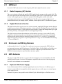
2.4 Principal Power Supply ........................................................................................ 26
2.5 Data Communications Equipment ....................................................................... 26
3 Installation and Set Up
27
3.1 Additional Equipment Required ........................................................................... 27
3.1.1 Selecting a GPS Antenna........................................................................... 27
3.1.2 Choosing a Coaxial Cable .......................................................................... 27
3.1.3 Power Supply Requirements ...................................................................... 28
3.2 Installation Overview............................................................................................ 29
3.2.1 Installing a GPSCard in a Wiring Harness and Enclosure.......................... 30
3.2.2 Mounting the GPS Antenna........................................................................ 33
3.2.3 Connecting the Antenna to the Receiver.................................................... 33
3.2.4 Applying Power to the Receiver ................................................................. 34
3.2.5 Connecting Data Communications Equipment........................................... 34
3.3 Additional Features and Information .................................................................... 35
3.3.1 Strobes ....................................................................................................... 35
3.3.2 USB (OEM4-G2/-G2L, FlexPak and ProPak-G2plus Only)........................ 37
3.3.3 Status Indicators......................................................................................... 37
OEM4 Family Installation and Operation User Manual Rev 16
3
Table of Contents
3.3.4 External Oscillator (OEM4-G2/-G2L and ProPak-G2plus Only) .................38
3.3.5 External Antenna LNA Power (OEM4-G2 Only) .........................................39
3.3.6 Mounting Bracket (ProPak-G2plus and ProPak-LBplus Only)....................39
4 Operation
40
4.1 Communications with the Receiver ......................................................................41
4.1.1 Serial Port Default Settings.........................................................................41
4.1.2 Communicating Using a Remote Terminal .................................................41
4.1.3 Communicating Using a Personal Computer..............................................41
4.2 Getting Started .....................................................................................................42
4.2.1 Starting the Receiver ..................................................................................42
4.2.2 Remote Terminal, PC and GPS Receiver...................................................43
4.3 Transmitting and Receiving Corrections...............................................................44
4.4 Enabling SBAS Positioning ..................................................................................46
4.5 Enabling L-Band Positioning (ProPak-LBplus Only).............................................46
4.6 Pass-Through Logging .........................................................................................47
4.7 Transferring Time Between Receivers .................................................................49
4.7.1 Procedures..................................................................................................49
5 Message Formats
51
5.1 RTCA-Format Messages......................................................................................51
5.1.1 RTCA1 ........................................................................................................51
5.1.2 RTCAEPHEM Type 7...............................................................................52
5.1.3 RTCAOBS Type 7 ....................................................................................52
5.1.4 RTCAREF Type 7 ....................................................................................53
5.2 RTCM-Format Messages .....................................................................................53
5.2.1 RTCM1........................................................................................................54
5.2.2 RTCM3 Base Station Parameters (RTK) ....................................................55
5.2.3 RTCM9 Partial Satellite Set Differential Corrections...................................55
5.2.4 RTCM15 Ionospheric Corrections...............................................................56
5.2.5 RTCM16 Special Message .........................................................................57
5.2.6 RTCM18 and RTCM19 Raw Measurements (RTK)....................................57
5.2.7 RTCM20 and RTCM21 Measurement Corrections (RTK) ..........................58
5.2.8 RTCM22 RTCM Extended Base Station Parameters (RTK) ......................58
5.2.9 RTCM59 Type 59N-0 NovAtel Proprietary Message (RTK) .......................58
5.3 RTCM Version 3.0 (RTCMV3) Messaging ...........................................................59
5.3.1 RTCM1001-RTCM1004 GPS RTK Observables ........................................59
5.3.2 RTCM1005 & RTCM1006 RTK Base Antenna Reference Point (ARP) .....60
5.4 CMR Format Messaging ......................................................................................60
5.4.1 Using RT-2 or RT-20 with CMR Format Messages ....................................61
5.5 NMEA Format Data Logs .....................................................................................62
6 Positioning Modes of Operation
63
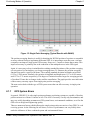
6.1 Single-Point ..........................................................................................................63
6.1.1 GPS System Errors.....................................................................................65
6.2 Satellite-Based Augmentation System (SBAS) ....................................................66
6.2.1 SBAS Receiver ...........................................................................................68
6.2.2 SBAS Commands and Logs .......................................................................69
6.3 Pseudorange Differential ......................................................................................69
4
OEM4 Family Installation and Operation User Manual Rev 16
Table of Contents
6.3.1 Pseudorange Algorithms ............................................................................ 69
6.3.2 Position Solutions ....................................................................................... 69
6.3.3 Dual Station Differential Positioning ........................................................... 70
6.4 L-Band Positioning............................................................................................... 73
6.4.1 Coverage .................................................................................................... 73
6.4.2 L-Band Service Levels................................................................................ 75
6.4.3 L-Band Commands and Logs..................................................................... 78
6.5 Carrier-Phase Differential .................................................................................... 78
6.5.1 Real-Time Kinematic (RTK)........................................................................ 80
7 PC Software and Firmware
88
7.1 GPSolution/Convert Installation ........................................................................... 88
7.2 GPSolution........................................................................................................... 88
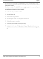
7.3 Convert ................................................................................................................ 91
7.3.1 Rinex Format .............................................................................................. 92
7.3.2 Convert Command Line Switches .............................................................. 93
7.4 USB Drivers Installation ....................................................................................... 95
7.4.1 Windows XP Installation ............................................................................. 95
7.4.2 Windows 2000 Installation.......................................................................... 96
7.4.3 Windows Driver Signing ............................................................................. 96
7.5 Firmware Upgrades & Updates............................................................................ 98
7.5.1 Upgrading Using the AUTH Command ...................................................... 99
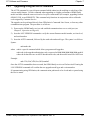
7.5.2 Updating Using the WinLoad Utility .......................................................... 100
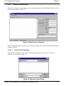
8 Built-In Status Tests
104
8.1 Overview ............................................................................................................ 104
8.2 Receiver Status Word ........................................................................................ 104
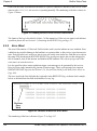
8.3 Error Strobe Signal ............................................................................................ 105
8.4 RXSTATUSEVENT Log..................................................................................... 105
8.5 Receiver Status Log........................................................................................... 105
8.5.1 Overview................................................................................................... 105
8.5.2 Error Word ................................................................................................ 106
8.5.3 Status Code Arrays .................................................................................. 107
8.5.4 Receiver Status Code............................................................................... 107
8.5.5 Auxiliary Status Codes ............................................................................. 107
8.5.6 Set and Clear Mask for all Status Code Arrays ........................................ 108
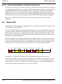
8.6 Status LED......................................................................................................... 108
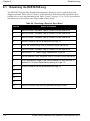
9 Troubleshooting
110
9.1 Examining the RXSTATUS Log ......................................................................... 112
APPENDICES
A
B
C
D
Technical Specifications
Electrostatic Discharge Control (ESD) Practices
Replacement Parts
Specifications Archive
OEM4 Family Installation and Operation User Manual Rev 16
115
150
153
155
5
Figures
1
2
3
4
5
6
7
8
9
10
11
12
13
14
15
16
17
18
19
20
21
22
23
24
25
26
27
28
29
30
31
32
33
34
35
36
37
38
39
40
41
42
43
44
45
6
OEM4-G2L GPSCard ................................................................................................... 17
OEM4-G2 GPSCard ..................................................................................................... 18
FlexPak Enclosure ........................................................................................................ 20
ProPak-G2plus Enclosure ............................................................................................ 21
ProPak-G2plus Rear Panel .......................................................................................... 21
ProPak-LBplus and Its Rear Panel ............................................................................... 22
GPS Receiver System Functional Diagram .................................................................. 24
Typical Receiver Installation ......................................................................................... 30
OEM4-G2L Connector and Indicator Locations ............................................................ 32
OEM4-G2 Connector and Indicator Locations .............................................................. 33
Typical Operational Configuration ................................................................................ 40
Pass-Through Log Data ............................................................................................... 48
1PPS Alignment ........................................................................................................... 50
Single-Point Averaging (Typical Results) ..................................................................... 64
Single-Point Averaging (Typical Results with WAAS) .................................................. 65
The SBAS Concept ...................................................................................................... 68
Typical Differential Configuration .................................................................................. 71
CDGPS Frequency Beams ........................................................................................... 74
CDGPS Percentage Coverage Map ............................................................................. 75
OmniSTAR Concept ..................................................................................................... 77
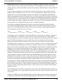
Typical RT-2 Horizontal Convergence - Static Mode ................................................... 83
Typical RT-2 Horizontal Convergence - Kinematic Mode ............................................. 83
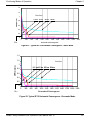
Typical RT-20 Convergence - Static Mode ................................................................... 85
Typical RT-20 Convergence - Kinematic Mode ............................................................ 85
Convert Screen Examples ............................................................................................ 91
Convert Command Line Arguments ............................................................................. 94
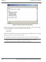
Main Screen of WinLoad ............................................................................................ 101
WinLoad’s Open Dialog .............................................................................................. 101
Open File in WinLoad ................................................................................................. 102
COM Port Setup ......................................................................................................... 102
Searching for Card ..................................................................................................... 102
Authorization Code Dialog .......................................................................................... 103
Update Process Complete .......................................................................................... 103
Location of Receiver Status Word .............................................................................. 105
Reading the Bits in the Receiver Status Word ........................................................... 106
Location of Receiver Error Word ................................................................................ 106
Reading the Bits in the Receiver Error Word .............................................................. 107
Status LED Flash Sequence Example ....................................................................... 109
OEM4-G2L Board Dimensions ................................................................................... 116
Top-view of 24-Pin Connector on the OEM4-G2L ...................................................... 119
OEM4-G2 Board Dimensions ..................................................................................... 120
Top-view of 40-Pin Connector on the OEM4-G2 ........................................................ 124
FlexPak Power Cable ................................................................................................. 130
FlexPak 13-Pin Serial Cable ....................................................................................... 131
FlexPak 13-Pin Serial Cable ....................................................................................... 132
OEM4 Family Installation and Operation User Manual Rev 16
Figures
46
47
48
49
50
51
52
53
54
55
56
57
58
59
60
61
62
63
64
65
66
67
68
69
70
71
72
FlexPak USB Cable .................................................................................................... 133
ProPak-G2plus Power Cable ...................................................................................... 137
ProPak-G2plus Null Modem Cable ............................................................................. 138
ProPak-G2plus Straight Through Serial Cable ........................................................... 139
ProPak-G2plus I/O Strobe Port Cable ........................................................................ 140
USB Serial Cable ........................................................................................................ 141
ProPak-LBplus Port Pin-Outs ..................................................................................... 144
ProPak-LBplus Power Cable ...................................................................................... 146
ProPak-LBplus 6-Pin Serial Cable .............................................................................. 147
ProPak-LBplus 7-Pin Serial Cable .............................................................................. 148
ProPak-LBplus 8-Pin Serial Cable .............................................................................. 149
ProPak-G2 Power Cable ............................................................................................ 161
ProPak-G2 (DB-9 Version) Y-Type Null Modem Cable .............................................. 162
ProPak-G2 (DB-9 Version) Straight Serial Cable ....................................................... 163
ProPak-G2 (DB-9 Version) I/O Strobe Port Cable ...................................................... 164
ProPak-G2 (LEMO Version) Null Modem Cable ........................................................ 165
ProPak-G2 (LEMO Version) Straight Serial Cable ..................................................... 166
OEM4 Board Dimensions ........................................................................................... 167
Top-view of 40-Pin Connector on the OEM4 .............................................................. 171
Euro4 Board Dimensions ............................................................................................ 173
Front-view of 64-Pin Connector on the Euro4 ............................................................ 176
PowerPak Power Adapter .......................................................................................... 181
PowerPak Y-Type Null Modem Cable ........................................................................ 182
ProPak-4E Power Cable ............................................................................................. 186
ProPak-4E Straight Through Serial Cable .................................................................. 187
ProPak-4E Null Modem Cable .................................................................................... 188
ProPak-4E Strobe Cable ............................................................................................ 189
OEM4 Family Installation and Operation User Manual Rev 16
7
Tables
1
2
3
4
5
6
7
8
9
10
11
12
13
14
15
16
17
18
19
20
21
22
23
24
25
26
27
28
29
30
31
32
33
34
35
36
37
38
39
40
41
42
43
44
45
8
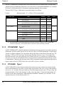
Enclosure Features Comparison ................................................................................... 19
ProPak-LBplus Interface................................................................................................ 23
NovAtel GPS Antenna Models ...................................................................................... 27
Voltage Input Ranges for GPSCards............................................................................. 28
Power Requirements for Enclosures ............................................................................. 29
Default Serial Port Configurations ................................................................................. 34
Available Strobe Signals on Receivers.......................................................................... 36
FlexPak Status Indicators.............................................................................................. 37
ProPak-G2plus Status Indicators .................................................................................. 38
ProPak-LBplus Status Indicators................................................................................... 38
Latency-Induced Extrapolation Error ............................................................................. 70
Comparison of RT-2 and RT-20 .................................................................................... 80
Summary of RTK Messages and Expected Accuracy................................................... 80
RT-2 Performance: Static Mode .................................................................................... 82
RT-2 Performance: Kinematic Mode ............................................................................. 82
RT-2 Degradation With Respect To Data Delay............................................................ 82
RT-20 Performance ....................................................................................................... 84
NovAtel Logs for Rinex Conversion............................................................................... 93
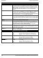
Troubleshooting based on Symptoms ......................................................................... 110
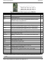
Resolving a Receiver Error Word ................................................................................ 112
Resolving an Error in the Receiver Status Word ......................................................... 113
FlexPak COM1 Port Pin-Out Descriptions .................................................................. 128
FlexPak COM2 Port Pin-Out Descriptions................................................................... 129
ProPak-G2plus Serial Port Pin-Out Descriptions ........................................................ 136
ProPak-G2plus I/O Port Pin-Out Descriptions............................................................. 136
ProPak-LBplus Power Port Pin-Out Descriptions ....................................................... 144
ProPak-LBplus COM1 Port Pin-Out Descriptions ....................................................... 144
ProPak-LBplus COM2 Port Pin-Out Descriptions ....................................................... 145
ProPak-LBplus COM3 Port Pin-Out Descriptions ....................................................... 145
Static-Accumulating Materials ..................................................................................... 151
Voltage Input Ranges for GPSCards........................................................................... 155
GPSCard RF Input Connectors ................................................................................... 155
GPSCard Power Inputs ............................................................................................... 155
Enclosure Power Inputs............................................................................................... 156
Default Serial Port Configurations ............................................................................... 156
PowerPak-4 Status Indicators ..................................................................................... 156
PowerPak-4E Status Indicators................................................................................... 156
ProPak-G2 Status Indicators ....................................................................................... 156
ProPak-G2 (DB-9 Version) Serial Port Pin-Out Descriptions ...................................... 159
ProPak-G2 (LEMO Version) Serial Port Pin-Out Descriptions .................................... 159
ProPak-G2 (DB-9 Version) I/O Port Pin-Out Descriptions........................................... 160
PowerPak Serial Port Pin-Out Descriptions ............................................................... 180
PowerPak I/O Port Pin-Out Descriptions..................................................................... 180
ProPak-4E Serial Port Pin-Out Descriptions .............................................................. 185
ProPak-4E I/O Port Pin-Out Descriptions.................................................................... 185
OEM4 Family Installation and Operation User Manual Rev 16
Software License
Software License
BY INSTALLING, COPYING, OR OTHERWISE USING THE SOFTWARE PRODUCT, YOU AGREE
TO BE BOUND BY THE TERMS OF THIS AGREEMENT. IF YOU DO NOT AGREE WITH THESE
TERMS OF USE, DO NOT INSTALL, COPY OR USE THIS ELECTRONIC PRODUCT (SOFTWARE,
FIRMWARE, SCRIPT FILES, OR OTHER ELECTRONIC PRODUCT WHETHER ON A CD OR
AVAILABLE ON THE COMPANY WEB SITE) (HEREINAFTER REFERRED TO AS "SOFTWARE").
1.
License: NovAtel Inc. ("NovAtel") grants you a non-exclusive, non-transferable license (not a sale) to,
where the Software will be used on NovAtel supplied hardware or in conjunction with other NovAtel
supplied software, use the Software with the product(s) as supplied by NovAtel. You agree not to use
the Software for any purpose other than the due exercise of the rights and licences hereby agreed to be
granted to you.
2.
Copyright: NovAtel owns, or has the right to sublicense, all copyright, trade secret, patent and other
proprietary rights in the Software and the Software is protected by national copyright laws,
international treaty provisions and all other applicable national laws. You must treat the Software like
any other copyrighted material except that you may make one copy of the Software solely for backup
or archival purposes (one copy may be made for each piece of NovAtel hardware on which it is
installed or where used in conjunction with other NovAtel supplied software), the media of said copy
shall bear labels showing all trademark and copyright notices that appear on the original copy. You
may not copy the product manual or written materials accompanying the Software. No right is
conveyed by this Agreement for the use, directly, indirectly, by implication or otherwise by Licensee of
the name of NovAtel, or of any trade names or nomenclature used by NovAtel, or any other words or
combinations of words proprietary to NovAtel, in connection with this Agreement, without the prior
written consent of NovAtel.
3.
Patent Infringement: NovAtel shall not be liable to indemnify the Licensee against any loss sustained
by it as the result of any claim made or action brought by any third party for infringement of any
letters patent, registered design or like instrument of privilege by reason of the use or application of
the Software by the Licensee or any other information supplied or to be supplied to the Licensee
pursuant to the terms of this Agreement. NovAtel shall not be bound to take legal proceedings against
any third party in respect of any infringement of letters patent, registered design or like instrument of
privilege which may now or at any future time be owned by it. However, should NovAtel elect to take
such legal proceedings, at NovAtel's request, Licensee shall co-operate reasonably with NovAtel in all
legal actions concerning this license of the Software under this Agreement taken against any third
party by NovAtel to protect its rights in the Software. NovAtel shall bear all reasonable costs and
expenses incurred by Licensee in the course of co-operating with NovAtel in such legal action.
Restrictions: You may not: (1) copy (other than as provided for in paragraph 2), distribute, transfer,
rent, lease, lend, sell or sublicense all or any portion of the Software; (2) modify or prepare derivative
works of the Software; (3) use the Software in connection with computer-based services business or
publicly display visual output of the Software; (4) transmit the Software over a network, by telephone
or electronically using any means; or (5) reverse engineer, decompile or disassemble the Software. You
agree to keep confidential and use your best efforts to prevent and protect the contents of the Software
from unauthorized disclosure or use.
4.
Term and Termination: This Agreement and the rights and licences hereby granted shall continue in
force in perpetuity unless terminated by NovAtel or Licensee in accordance herewith. In the event
that the Licensee shall at any time during the term of this Agreement: i) be in breach of its obligations
hereunder where such breach is irremediable or if capable of remedy is not remedied within 30 days
of notice from NovAtel requiring its remedy; or ii) be or become bankrupt or insolvent or make any
composition with its creditors or have a receiver or manager appointed of the whole or any part of its
OEM4 Family Installation and Operation User Manual Rev 16
9
Software License
undertaking or assets or (otherwise as a solvent company for the purpose of and followed by an
amalgamation or reconstruction hereunder its successor shall be bound by its obligations hereunder)
commence to be wound up; or iii) be acquired or otherwise come under the direct or indirect control
of a person or persons other than those controlling it, then and in any event NovAtel may forthwith by
notice in writing terminate this Agreement together with the rights and licences hereby granted by
NovAtel. Licensee may terminate this Agreement by providing 30 days prior written notice to
NovAtel. Upon termination, for any reasons, the Licensee shall promptly, on NovAtel's request,
return to NovAtel or at the election of NovAtel destroy all copies of any documents and extracts
comprising or containing the Software. The Licensee shall also erase any copies of the Software
residing on Licensee's computer equipment. Termination shall be without prejudice to the accrued
rights of either party, including payments due to NovAtel. This provision shall survive termination of
this Agreement howsoever arising.
5.
Warranty:
a. For 90 days from the date of shipment of new purchased product, NovAtel warrants that the media (for
example, compact disk) on which the Software is contained will be free from defects in materials and
workmanship. This warranty does not cover damage caused by improper use or neglect.
b. NovAtel does not warrant the contents of the Software or that it will be error free. The Software is furnished
"AS IS" and without warranty as to the performance or results you may obtain by using the Software. The entire
risk as to the results and performance of the Software is assumed by you.
6.
Indemnification: NovAtel shall be under no obligation or liability of any kind (in contract, tort or
otherwise and whether directly or indirectly or by way of indemnity contribution or otherwise
howsoever) to the Licensee and the Licensee will indemnify and hold NovAtel harmless against all or
any loss, damage, actions, costs, claims, demands and other liabilities or any kind whatsoever (direct,
consequential, special or otherwise) arising directly or indirectly out of or by reason of the use by the
Licensee of the Software whether the same shall arise in consequence of any such infringement,
deficiency, inaccuracy, error or other defect therein and whether or not involving negligence on the
part of any person.
7.
For Software UPDATES and UPGRADES, and regular customer support, contact the NovAtel GPS
Hotline at 1-800-NOVATEL (U.S. or Canada only), or 403-295-4900, Fax 403-295-4901, e-mail to
[email protected], website: http://www.novatel.com or write to:
NovAtel Inc.
Customer Service Dept.
1120 - 68 Avenue NE,
Calgary, Alberta, Canada T2E 8S5
8.
Disclaimer of Warranty and Limitation of Liability:
a. THE WARRANTIES IN THIS AGREEMENT REPLACE ALL OTHER WARRANTIES, EXPRESS OR
IMPLIED, INCLUDING ANY WARRANTIES OF MERCHANTABILITY OR FITNESS FOR A
PARTICULAR PURPOSE. NovAtel DISCLAIMS AND EXCLUDES ALL OTHER WARRANTIES. IN NO
EVENT WILL NovAtel's LIABILITY OF ANY KIND INCLUDE ANY SPECIAL, INCIDENTAL OR
CONSEQUENTIAL DAMAGES, INCLUDING LOST PROFITS, EVEN IF NovAtel HAS KNOWLEDGE
OF THE POTENTIAL LOSS OR DAMAGE.
b. NovAtel will not be liable for any loss or damage caused by delay in furnishing the Software or any other
performance under this Agreement.
c. NovAtel's entire liability and your exclusive remedies for our liability of any kind (including liability for
negligence) for the Software covered by this Agreement and all other performance or non-performance by
NovAtel under or related to this Agreement are to the remedies specified by this Agreement.
This Agreement is governed by the laws of the Province of Alberta, Canada. Each of the parties hereto
irrevocably attorns to the jurisdiction of the courts of the Province of Alberta.
10
OEM4 Family Installation and Operation User Manual Rev 16
Warranty Policy
Warranty Policy
NovAtel Inc. warrants that its Global Positioning System (GPS) products are free from defects in materials and
workmanship, subject to the conditions set forth below, for the following periods of time:
OEM4-G2L, or OEM4-G2 GPSCard Receivers
FlexPak, ProPak-G2plus, or ProPak-LBplus
GPSAntenna™ Series
Cables and Accessories
Software Support
One (1) Year
One (1) Year
One (1) Year
Ninety (90) Days
One (1) Year
Date of sale shall mean the date of the invoice to the original customer for the product. NovAtel’s responsibility
respecting this warranty is solely to product replacement or product repair at an authorized NovAtel location.
Determination of replacement or repair will be made by NovAtel personnel or by technical personnel expressly
authorized by NovAtel for this purpose.
THE FOREGOING WARRANTIES DO NOT EXTEND TO (I) NONCONFORMITIES, DEFECTS OR
ERRORS IN THE PRODUCTS DUE TO ACCIDENT, ABUSE, MISUSE OR NEGLIGENT USE OF
THE PRODUCTS OR USE IN OTHER THAN A NORMAL AND CUSTOMARY MANNER, ENVIRONMENTAL CONDITIONS NOT CONFORMING TO NOVATEL’S SPECIFICATIONS, OR FAILURE TO FOLLOW PRESCRIBED INSTALLATION, OPERATING AND MAINTENANCE
PROCEDURES, (II) DEFECTS, ERRORS OR NONCONFORMITIES IN THE PRODUCTS DUE TO
MODIFICATIONS, ALTERATIONS, ADDITIONS OR CHANGES NOT MADE IN ACCORDANCE
WITH NOVATEL’S SPECIFICATIONS OR AUTHORIZED BY NOVATEL, (III) NORMAL WEAR
AND TEAR, (IV) DAMAGE CAUSED BY FORCE OF NATURE OR ACT OF ANY THIRD PERSON,
(V) SHIPPING DAMAGE; OR (VI) SERVICE OR REPAIR OF PRODUCT BY THE DEALER WITHOUT PRIOR WRITTEN CONSENT FROM NOVATEL. IN ADDITION, THE FOREGOING WARRANTIES SHALL NOT APPLY TO PRODUCTS DESIGNATED BY NOVATEL AS BETA SITE TEST
SAMPLES, EXPERIMENTAL, DEVELOPMENTAL, PREPRODUCTION, SAMPLE, INCOMPLETE
OR OUT OF SPECIFICATION PRODUCTS OR TO RETURNED PRODUCTS IF THE ORIGINAL
IDENTIFICATION MARKS HAVE BEEN REMOVED OR ALTERED. THE WARRANTIES AND
REMEDIES ARE EXCLUSIVE AND ALL OTHER WARRANTIES, EXPRESS OR IMPLIED, WRITTEN OR ORAL, INCLUDING THE IMPLIED WARRANTIES OF MERCHANTABILITY OR FITNESS FOR ANY PARTICULAR PURPOSE ARE EXCLUDED. NOVATEL SHALL NOT BE LIABLE
FOR ANY LOSS, DAMAGE, EXPENSE, OR INJURY ARISING DIRECTLY OR INDIRECTLY OUT
OF THE PURCHASE, INSTALLATION, OPERATION, USE OR LICENSING OR PRODUCTS OR
SERVICES. IN NO EVENT SHALL NOVATEL BE LIABLE FOR SPECIAL, INDIRECT, INCIDENTAL OR CONSEQUENTIAL DAMAGES OF ANY KIND OR NATURE DUE TO ANY CAUSE.
There are no user serviceable parts in the GPS receiver and no maintenance is required. When the status code
indicates that a unit is faulty, replace with another unit and return the faulty unit to NovAtel Inc.
Before shipping any material to NovAtel or Dealer, please obtain a Return Material Authorization (RMA)
number from the point of purchase. You may also visit our website at http://www.novatel.com and select
Support | Repair Request from the side menu.
Once you have obtained an RMA number, you will be advised of proper shipping procedures to return any
defective product. When returning any product to NovAtel, please return the defective product in the original
packaging to avoid ESD and shipping damage.
OEM4 Family Installation and Operation User Manual Rev 16
11
Customer Service
Customer Service
Firmware UPDATES and UPGRADES
Firmware updates are firmware revisions to an existing model, which improve basic functionality of
the GPS receiver. During the one-year warranty coverage following initial purchase, firmware updates
are supplied free of charge. After the warranty has expired, firmware updates and updated manuals
may be subject to a nominal charge.
Firmware upgrades are firmware releases, which increase basic functionality of the receiver from one
model to a higher level model type. When available, upgrades may be purchased at a price, which is
the difference between the two model types on the current NovAtel GPS Price List plus a nominal
service charge.
Firmware updates and upgrades are accomplished through NovAtel authorized dealers.
Contact your local NovAtel dealer first for more information. To locate a dealer in your area or if the
problem is not resolved, contact NovAtel Inc. directly using one of the following methods:
Call the NovAtel GPS Hotline at 1-800-NOVATEL (U.S. & Canada), or 403-295-4900 (international)
Fax: 403-295-4901
E-mail: [email protected]
Website: http://www.novatel.com
Write: NovAtel Inc., Customer Service Dept., 1120 - 68 Avenue NE, Calgary, AB., Canada, T2E 8S5
Before contacting NovAtel Customer Service regarding software concerns, please do the
following:
1. Issue a FRESET command
2. Log the following data to a file on your PC for 30 minutes
RXSTATUSB
RAWEPHEMB
RANGEB
BESTPOSB
RXCONFIGA
VERSIONB
once
onchanged
ontime 1
ontime 20
once
once
3. Send the file containing the log to NovAtel Customer Service, using either the NovAtel ftp site
at ftp://ftp.novatel.ca/incoming or the [email protected] e-mail address.
If there is a hardware problem that has not been resolved, please send a list of the troubleshooting
steps you have taken and their result. See also Chapter 9 on Page 110.
12
OEM4 Family Installation and Operation User Manual Rev 16
Notice
Notice
The following notices apply to the ProPak-LBplus, ProPak-G2plus and FlexPak-G2L.
FCC NOTICE
This equipment has been tested and found to comply with the radiated and conducted emission limits
for a Class B digital device, for both CISPR 22 and Part 15 of the FCC rules. These limits are
designed to provide reasonable protection against harmful interference in a residential installation.
This equipment generates, uses, and can radiate radio frequency energy and, if not installed and used
in accordance with the instructions, may cause harmful interference to radio communications.
However, there is no guarantee that interference will not occur in a particular installation. If this
equipment does cause harmful interference to radio or television reception, which can be determined
turning the equipment off and on, the user is encouraged to try to correct the interference by one or
more of the following measures:
• Re-orient or relocate the receiving antenna
• Increase the separation between the equipment and the receiver
• Connect the equipment to an outlet on a circuit different from that to which the
receiver is connected
• Consult the dealer or an experienced radio/TV technician for help
IMPORTANT:
In order to maintain compliance with the limits of a Class B digital device, it is
required to use properly shielded interface cables (such as Belden #9539 or
equivalent) when using the serial data ports, and double-shielded cables (such as
Belden #9945 or equivalent) when using the I/O strobe port.
WARNING: Changes or modifications to this equipment not expressly approved by NovAtel
Inc. could result in violation of Part 15 of the FCC rules.
CE NOTICE
The enclosures carry the CE mark.
WARNING: This is a Class B product. In a domestic environment this product may cause radio
interference in which case the user may be required to take adequate measures.
"Hereby, NovAtel Inc. declares that this ProPak-G2plus, ProPak-LBplus and FlexPak-G2L are in
compliance with the essential requirements and other relevant provisions of Directive 1999/5/EC."
OEM4 Family Installation and Operation User Manual Rev 16
13
Notice
Electromagnetic Compatibility (EMC)
Common Regulatory Testing
•
•
•
•
•
•
•
•
FCC, Part 15
EN 61000-6-1
• EN 61000-6-3
EN 61000-4-2
EN 61000-4-3
EN 61000-4-4
EN 61000-4-6
EN 61000-4-8
ENV 50204
Radiated Emissions, Class B
Generic Immunity
Generic Emissions, Class B
Electrostatic Discharge Immunity
Radiated RF EM Field Immunity Test
Electrical Fast Transient/Burst Test
Conducted Immunity
Magnetic Field Immunity
Radiated Immunity, Keyed Carrier, 900 MHz Phone Band
ProPak-G2plus Additional Testing
•
•
•
•
•
•
EN 61000-6-2
EN 61000-4-5
EN 61000-4-11
IEC/EN 60950
EN 60555-2
EN 60555-3
Generic Immunity - Industrial
Surge Immunity
Voltage Dips and Interruptions
Safety of Information Technology Equipment
Harmonic Emissions
Voltage Changes, Fluctuations and Flicker
FlexPak-G2L Additional Testing
•
•
EN 61000-4-5
IEC/EN 60950
Surge Immunity
Safety of Information Technology Equipment
ProPak-LBplus Additional Testing
•
•
ISO 7637-1
IEC/EN 60950
Conducted Transients
Safety of Information Technology Equipment
Lightning Protection Notice
1.
Do not install the external antenna lines extra-building during a lightning storm.
2.
A primary lightning protection device, from Polyphaser Corporation for example, must be
provided by the operator/customer according to local building codes as part of the extra-building
installation to ensure transient voltage levels of less than 600 V maximum.
ProPak-G2plus Warning
This product is capable of providing power output on pin 4 of its COM2 and AUX ports. COM1 pins
6 and 9 provide universal serial bus (USB) signals. Cross connecting a ProPak-G2plus using a null
modem cable to COM1 from any serial port other than COM1 may damage the unit and void your
warranty. To prevent this damage cross connect the receivers using COM2 or COM3.
14
OEM4 Family Installation and Operation User Manual Rev 16
Foreword
Congratulations!
Foreword
Thank you for purchasing a NovAtel receiver. Whether you have bought a stand alone GPSCard or a
packaged receiver you will have also received companion documents for the product. Volume 1 will
help you get the hardware operational and provide further general information. Afterwards, Volume 2
will be your primary OEM4 family command and logging reference source.
Scope
The OEM4 Family of Receivers User Manual - Volume 1 contains sufficient information on the
installation and operation of the OEM4-G2L and OEM4-G2 GPSCards to allow you to effectively
integrate and fully operate them. There is also information on the FlexPak, ProPak-G2plus and
ProPak-LBplus enclosures. After the addition of accessories, user-supplied data communications
equipment and a power supply, the receivers are ready to go.
The OEM4 family receivers utilize a comprehensive user-interface command structure, which
requires communications through its communications (COM) ports. This manual is volume one of a
two volume set. The second volume, the Command and Log Reference, lists and describes the various
receiver commands and logs. Please remember that since each receiver is shipped from the distributor
with a customer-specific list of features, some commands or logs may not be applicable to your
model. Other supplementary manuals may be included to accommodate special models and software
features with unique functionality. It is recommended that these documents be kept together for easy
reference.
It is beyond the scope of this manual to provide details on service or repair. Please contact your local
NovAtel dealer for any customer-service related inquiries, see Customer Service on Page 12.
User Manual Updates
This manual has been revised to include information on a new L-Band service. NovAtel Inc. has
developed OEM4-G2L-based products to use the Canada-Wide Differential Global Positioning
System (CDGPS), a free signal operated by the Canadian government. See Enabling L-Band
Positioning (ProPak-LBplus Only) starting on Page 46 and L-Band Positioning starting on Page 73.
The most up-to-date version of this manual set and any related addendum can be downloaded from the
Documentation Updates section of www.novatel.com.
Prerequisites
The OEM4-G2L and OEM4-G2 are OEM products requiring the addition of an enclosure and
peripheral equipment before becoming a fully functional GPS receiver. The installation chapters of
this document provide information concerning the installation requirements and considerations for the
GPSCards and their enclosures.
Conventions
The terms OEM4-G2 and OEM4-G2L will not be used in this manual unless a specific detail refers to
it alone. The term receiver will infer that the text is applicable to an OEM4-G2L or OEM4-G2, either
stand-alone or in an enclosure, unless otherwise stated.
OEM4 Family Installation and Operation User Manual Rev 16
15
Chapter 1
1.1
Introduction
Overview of the OEM4 Family
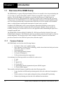
The OEM4 family is a group of high-performance GPS receivers capable of receiving and tracking the
L1 C/A Code, L1 and L2 carrier phase, and L2 P Code (or encrypted Y Code) of up to 12 GPS
satellites. The ProPak-LBplus also includes a second card which receives L-Band signals for
differential corrections. With patented Pulse Aperture Correlator (PAC) technology and a powerful
32-bit processor, the OEM4 family receivers offer multipath-resistant processing at high data update
rates. Excellent acquisition and re-acquisition times allow the receivers to operate in environments
where very high dynamics and frequent interruption of signals can be expected.
In addition, the OEM4 family offers system integrators unparalleled flexibility in areas such as
configuration and specification of output data and control signals. Multiple software models are
available, allowing you to better fit the receiver to the application while maintaining the option for a
compatible upgrade path.
The OEM4 family includes OEM4-G2/OEM4-G2L GPSCards and FlexPak, ProPak-G2plus and
ProPak-LBplus enclosures. The GPSCards, which are provided as printed circuit boards, are ideal for
custom integration. The enclosures above offer a complete solution, a protective enclosure that
provides an interface to the GPSCard’s power, data, and status signals.
1.1.1
Common Features
All OEM4 family receivers have the following features:
•
•
•
•
•
•
24 channel “all-in-view” parallel tracking
Pulse Aperture Correlator (PAC) technology, which is described in the Multipath section
of the GPS+ Reference Manual
Fast reacquisition
Fully field-upgradeable firmware
Low power consumption
20 Hz raw data and position output rates
At a minimum, the following models are available for each receiver:
•
•
•
•
•
•
L1 only
L1/L2
L1 plus RT-20
L1/L2 plus RT-2
L1 plus Satellite-Based Augmentation System (SBAS) support
L1/L2 plus SBAS support
Those models with dual-frequency capabilities make the following possible:
•
•
•
16
Longer baselines in differential positioning mode, due to the reduction of atmospheric
errors
Faster resolution of carrier-phase ambiguities when performing RTK positioning
Enhanced positioning precision due to the additional measurements
OEM4 Family Installation and Operation User Manual Rev 16
Introduction
1.2
Chapter 1
GPSCards
The OEM4 family GPSCards consist of a single printed circuit board with integrated radio frequency
(RF) and digital sections. They are designed for flexibility of integration and configuration. After
installation with a power source, mounting structure, GPS antenna, and data communications
equipment, NovAtel’s GPSCards are ready for the most demanding surveying, positioning, and
navigation applications.
Two different GPSCards, described in the sections that follow, are included in the OEM4 family:
•
•
1.2.1
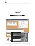
OEM4-G2L
OEM4-G2
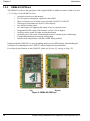
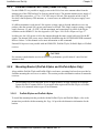
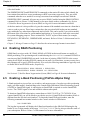
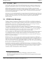
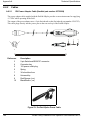
OEM4-G2L GPSCard
The OEM4-G2L provides the best features of the OEM4 family in a compact, low-power card. In
addition to the functionality given in Section 1.1.1 on Page 16, the OEM4-G2L offers:
•
•
•
•
•
•
•
•
•
40% smaller than the OEM4-G2
15% less power consumption compared to the OEM4-G2 and 35% less than the original
OEM4
Two serial ports
USB support (with firmware version 2.100 or higher)
An external oscillator input
Two mark inputs for triggering the output of logs on external events
Programmable PPS output (with firmware version 2.100 or higher)
Auxiliary strobe signals for status and synchronization
Software load compatibility with other OEM4 family products
Included with the OEM4-G2L is a wrist-grounding strap to prevent ESD damage when handling the
card and a CD containing NovAtel’s GPS PC utilities and product documentation.
For technical specifications on the OEM4-G2L, please see Section A.2, starting on Page 116.
Top
Bottom
Figure 1: OEM4-G2L GPSCard
OEM4 Family Installation and Operation User Manual Rev 16
17
Chapter 1
1.2.2
Introduction
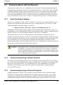
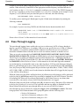
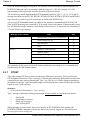
OEM4-G2 GPSCard
The OEM4-G2 is the second generation of the original OEM4. In addition to what is listed in Section
1.1.1 on Page 16, the OEM4-G2 offers:
•
•
•
•
•
•
•
•
•
•
•
An improved processor and memory
20% less power consumption compared to the OEM4
Three serial ports, one of which is user-selectable for RS-232 or RS-422
USB support (with firmware version 2.100 or higher)
An external oscillator input
Two mark inputs for triggering the output of logs on external events
Programmable PPS output (with firmware version 2.100 or higher)
Auxiliary strobe signals for status and synchronization
On-board power conversion, eliminating the need for external power conditioning
Voltage and temperature monitoring and reporting
Software load compatibility with other OEM4 family products
Included with the OEM4-G2 is a wrist-grounding strap to prevent ESD damage when handling the
card and a CD containing NovAtel’s GPS PC utilities and product documentation.
For technical specifications on the OEM4-G2, please see Section A.3, starting on Page 120.
Top
Bottom
Figure 2: OEM4-G2 GPSCard
18
OEM4 Family Installation and Operation User Manual Rev 16
Introduction
1.3
Chapter 1
Enclosures
The OEM4 family GPSCards can be housed in a ProPak-G2plus, ProPak-LBplus or FlexPak
enclosure to provide a complete receiver solution. When connected to an antenna and a power source,
the enclosure and associated GPSCard together form a fully functioning GPS receiver.
The enclosures offer protection against environmental conditions and RF interference. In addition,
they provide an easy-to-use interface to the GPSCard’s data, power, and status signals. The enclosures
offer GPS integrators an effective, self-contained system for indoor applications while also providing
a rugged, water, shock, and vibration resistant housing for outdoor applications.
The table below provides a comparison between the features available on the various enclosures. The
sections that follow give details on each of them.
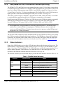
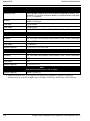
Table 1: Enclosure Features Comparison
Feature
ProPak-G2plus
ProPak-LBplus
FlexPak
GPSCard
Supported
OEM4-G2
OEM4-G2
OEM4-G2L
Serial Ports
3 DB-9P
connectors
3 Switchcraft
connectors
2 Deutsch
connectors
USB
Yes
Not available
Yes
Strobe Port
DB-9S
connector
Switchcraft a
connector
Deutsch b
connector
Input Voltage
+7 to +18 V
+7 to +15 V
+6 to +18 V
L-Band Differential
Not available
Corrections c
Yes
Not available
IMU Support d
Yes
Not available
Yes
a. For the ProPak-LBplus, the strobes are available at the COM1
connector, which also provides RS-232 signals for one of the
serial ports.
b. If Pin# 1 on the Deutsch connector is grounded, the COM2
communications mode is set to RS-422.
c. A subscription to the OmniSTAR or CDGPS service is
required.
d. If applicable, refer also to your SPAN User Manual
OEM4 Family Installation and Operation User Manual Rev 16
19
Chapter 1
1.3.1
Introduction
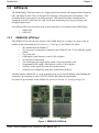
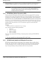
FlexPak
NovAtel's FlexPak is a rugged, waterproof housing for the OEM4-G2L positioning engine. As a
result, the FlexPak can deliver centimeter-level positioning in a compact, lightweight enclosure. It
provides dual-frequency positioning with a USB interface and an API option for supporting custom
applications.
The FlexPak offers the following features:
• A shock and dust resistant enclosure
• Waterproof to IEC 60529 standard IPX7
• Low power consumption
• Two serial ports (COM1 is RS-232 and COM2 is RS-232/RS-4221)
• USB support
• PPS output
• Configurable event inputs
• Indicators for position, communication status and power
The following accessories are included with the FlexPak:
•
•
•
•
•
1 12V power adapter cable
1 null modem serial cable with DB-9 connector
1 straight through serial cable with DB-9 connector
1 USB serial cable
A CD containing NovAtel’s GPS PC utilities and product documentation
For technical specifications on the FlexPak, please see Section A.4, starting on Page 126.
Figure 3: FlexPak Enclosure
1.
20
If Pin# 1 on the Deutsch connector is grounded, the COM2 communications mode is set to
RS-422.
OEM4 Family Installation and Operation User Manual Rev 16
Introduction
1.3.2
Chapter 1
ProPak-G2plus
The ProPak-G2plus provides a hardware interface between your equipment and the NovAtel OEM4G2 GPSCard. It is a rugged, sealed enclosure that provides protection against adverse environments. It
has DB-9 connectors to access data and status signals.
The ProPak-G2plus offers the following features:
•
•
•
•
•
A mounting enclosure with a PCB interconnect back plane
Three serial ports provided on three DB-9P connectors
Auxiliary status and synchronization signals
GPS antenna and power ports
Indicators to provide power and communication status
The following accessories are included with the ProPak-G2plus:
•
•
•
1 12 V power adapter cable
2 or more data cables
A CD containing NovAtel’s GPS PC utilities and product documentation
For technical specifications on the ProPak-G2plus, please see Section A.5, starting on Page 134.
Figure 4: ProPak-G2plus Enclosure
Figure 5: ProPak-G2plus Rear Panel
OEM4 Family Installation and Operation User Manual Rev 16
21
Chapter 1
1.3.3
Introduction
ProPak-LBplus
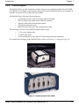
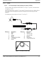
The NovAtel ProPak-LBplus provides a hardware interface between your equipment and the NovAtel
OEM4-G2 GPSCard. Additionally, within the ProPak-LBplus, an L-Band receiver provides
correction data. As shown in Figure 6, the ProPak-LBplus is a rugged, sealed enclosure, suitable for
adverse conditions.
In order to receive L-Band corrections, a subscription to the OmniSTAR service, or use of the free
Canada-Wide Differential Global Positioning System (CDGPS) signal, is required. See Section
4.5 on Page 46 or the ProPak-LBplus Quick Start Guide, provided with the receiver, for details.
In addition to support for L-Band positioning, the ProPak-LBplus provides the following:
•
•
•
•
•
A rugged, environmentally-sealed enclosure
3 serial ports with Switchcraft-brand connectors
GPS antenna and power ports
Auxiliary strobe signals for status and synchronization
Indicator to provide status information
The following accessories are included with the ProPak-LBplus:
•
•
•
1 12 V power adapter cable
3 straight through serial port cables
A CD containing NovAtel’s GPS PC utilities and product documentation
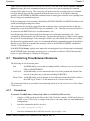
For technical specifications on the ProPak-LBplus, please see Section A.6, starting on Page 142.
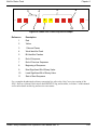
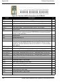
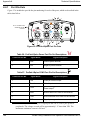
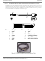
Figure 6: ProPak-LBplus and Its Rear Panel
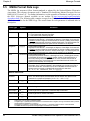
Figure 6, to the right, shows the six ports on the rear panel of the ProPak-LBplus that are labeled with
icons. Table 2 on Page 23 provides information on these ports, including the name used to reference
each of them throughout this manual.
22
OEM4 Family Installation and Operation User Manual Rev 16
Introduction
Chapter 1
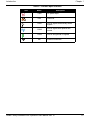
Table 2: ProPak-LBplus Interface
Icon
Name
Description
PWR
DC power input
RES
Reserved
COM1
RS232 signals and auxiliary strobe
signals
COM2
RS232 signals with optional flow
control
COM3
RS232 and general I/O signals
ANT
Antenna connection
OEM4 Family Installation and Operation User Manual Rev 16
23
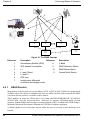
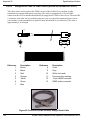
Chapter 2
Receiver System Overview
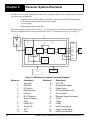
In addition to a NovAtel OEM4 family GPSCard, a complete GPS receiver system typically contains
four other major components:
• A ProPak-G2plus, ProPak-LBplus, FlexPak or custom enclosure and wiring harness
• A GPS antenna (and optional LNA power supply)
• A power supply
• Data communications equipment
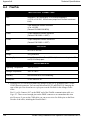
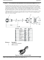
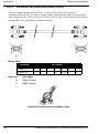
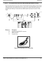
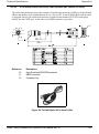
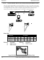
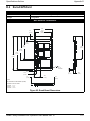
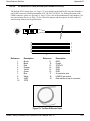
The overall system is represented in Figure 7. A brief description of each section follows the figure.
Details of installation and set up are provided in Chapter 3, Installation and Set Up on Page 27.
16
1
2
3
17
4
5
7
6
8
9
18
10
11
13
12
19
20
21
22
23
24
15
14
Figure 7: GPS Receiver System Functional Diagram
Reference
1
2
3
4
5
6
7
8
9
10
11
12
24
Description
Reference
Enclosure
GPSCard
RF Section
Digital Section
Controls
RF-IF Sections
Signal Processor
Clock
22-Bit CPU
System I/O
AGC
Clock
13
14
15
16
17
18
19
20
21
22
23
24
Description
VCTCXO
Optional LNA Power
Power Supply
GPS Antennaand LNA
RF and Power
Data and Signal Processing
COM1
COM2
COM3
Input Timing Signal
Output Timing Signal
USB Communication
OEM4 Family Installation and Operation User Manual Rev 16
Receiver System Overview
2.1
Chapter 2
GPSCard
NovAtel’s GPSCards consist of a radio frequency (RF) and a digital electronics section.
2.1.1
Radio Frequency (RF) Section
The receiver obtains a filtered and amplified GPS signal from the antenna via the coaxial cable. The
RF section performs the translation from the incoming RF signal to an IF signal usable by the digital
section. It also supplies power to the active antenna’s LNA through the coaxial cable while
maintaining isolation between the DC and RF paths. The RF section can reject a high level of
potential interference (for example, MSAT, Inmarsat, cellular phone, and TV sub-harmonic signals).
2.1.2
Digital Electronics Section
The digital section of the receiver receives a down-converted, amplified GPS signal which it digitizes
and processes to obtain a GPS solution (position, velocity and time). The digital section consists of an
analog-to-digital converter, a 32-bit system processor, memory, control and configuration logic, signal
processing circuitry, serial peripheral devices, and supporting circuitry.
The digital section performs the translations and calculations necessary to convert the IF analog
signals into usable position and status information. It also handles all I/O functions, including the
auxiliary strobe signals, which are described in detail in Section 3.3.1 on Page 35. For input and
output levels please see Appendix A, Input/Output Strobes on Page 118 for the OEM4-G2L and Page
123 for the OEM4-G2.
2.2
Enclosure and Wiring Harness
As discussed in Section 1.3 on Page 19, an enclosure is necessary to protect the GPSCard from
environmental exposure and RF interference. If a ProPak-G2plus, ProPak-LBplus or FlexPak is not
being used as the enclosure, a wiring harness will also be required to provide an interface to the
GPSCard’s antenna and power inputs and data and status signals.
2.3
GPS Antenna
The purpose of the GPS antenna is to convert the electromagnetic waves transmitted by the GPS
satellites into RF signals. An active GPS antenna is required for the receiver to function properly.
NovAtel’s active antennas are recommended.
2.3.1
Optional LNA Power Supply
Power for the antenna LNA is normally supplied by the receiver. However, if a different type of
antenna is required that is incompatible with this supply, then you could connect an external power
source to the receiver.
External LNA power is not possible with a ProPak-G2plus, ProPak-LBplus or FlexPak receiver.
OEM4 Family Installation and Operation User Manual Rev 16
25
Chapter 2
2.4
Receiver System Overview
Principal Power Supply
A single external power supply capable of delivering 5 W is necessary to operate the receiver. See
Appendix A, Technical Specifications starting on Page 115 for details.
WARNING:
2.5
If the voltage supplied is below the minimum specification, the receiver will
suspend operation. If the voltage supplied is above the maximum
specification, the receiver may be permanently damaged, voiding your
warranty.
Data Communications Equipment
A PC or other data communications equipment is necessary to communicate with the receiver and, if
desired, to store data generated by the receiver.
26
OEM4 Family Installation and Operation User Manual Rev 16
Chapter 3
Installation and Set Up
This chapter contains instructions and tips to set up your NovAtel receiver to create a GPS receiver
system similar to that described in Chapter 2, Receiver System Overview on Page 24.
3.1
Additional Equipment Required
In order for the receiver to perform optimally, the following additional equipment is required:
•
•
•
•
•
•
•
An interface for power, communications, and other signals and an enclosure to protect
against the environment (if your receiver has been purchased as a GPSCard without an
enclosure)
A NovAtel GPS antenna
A quality coaxial cable (and interconnect adapter cable as necessary)
Data communications equipment capable of serial communications
A serial cable (if not included with the receiver)
A power supply
A power cable (if not included with the receiver)
CAUTION:
3.1.1
When the OEM4 family receiver is installed in a permanent location, such
as in a building, it should be protected by a lightning protection device
according to local building codes. See also Warranty Policy on Page 11.
Selecting a GPS Antenna
An active antenna is required because its low-noise amplifier (LNA) boosts the power of the incoming
signal to compensate for the line loss between the antenna and the receiver.
NovAtel offers a variety of single and dual-frequency GPS antenna models, as indicated in the table
below. All include band-pass filtering and an LNA. The GPS antenna you choose will depend on your
particular application. Each of these models offer exceptional phase-center stability as well as a
significant measure of immunity against multipath interference. Each one has an environmentallysealed radome.
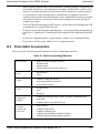
Table 3: NovAtel GPS Antenna Models
Models
3.1.2
Frequencies Supported
701,
L1 only
702, 533, 532
L1 and L2
600-LB
L1 and L2 plus L-Band
Choosing a Coaxial Cable
An appropriate coaxial cable is one that is matched to the impedance of the antenna and receiver being
OEM4 Family Installation and Operation User Manual Rev 16
27
Chapter 3
Installation and Set Up
used (50 ohms), and whose line loss does not exceed 10.0 dB. If the limit is exceeded, excessive
signal degradation will occur and the receiver may not be able to meet its performance specifications.
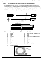
NovAtel offers a variety of coaxial cables to meet your GPS antenna interconnection requirements,
including:
•
•
5, 15, or 30 m antenna cables with TNC male connectors on both ends (NovAtel part
numbers C006, C016 and C032 respectively)
22 cm interconnect adapter cable with MMCX male and TNC female connectors (NovAtel
part number GPS-C002)
Note that a conversion is required between the female MMCX connector on the OEM4-G2L and
OEM4-G2 GPSCards, and the female TNC connector on Novatel’s GPS antennas.
Your local NovAtel dealer can advise you about your specific configuration. Should your application
require the use of cable longer than 30 m you will find the application note RF Equipment Selection
and Installation at our website, www.novatel.com, or you may obtain it from NovAtel Customer
Service directly.
High-quality coaxial cables should be used because a mismatch in impedance, possible with lower
quality cable, produces reflections in the cable that increase signal loss. Though it is possible to use
other high-quality antenna cables, the performance specifications of the OEM4 family receivers are
warranted only when used with NovAtel-supplied accessories.
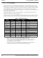
3.1.3
Power Supply Requirements
This section contains information on the requirements for the input power to the receiver. See
Appendix A, Technical Specifications starting on Page 115 for more power supply specifications.
WARNING:
3.1.3.1
If the voltage supplied is below the minimum specification, the receiver will
suspend operation. If the voltage supplied is above the maximum
specification, the receiver may be permanently damaged, voiding your
warranty.
GPSCards
The OEM4-G2 GPSCard contains a DC to DC converter that is very tolerant to noise and ripple at its
input. A tightly regulated input supply to the card is not required, as long as it falls within the given
input range. A tightly regulated input supply to the OEM4-G2L GPSCard is required. The power
supply used for any GPSCard should be capable of 5 W. The voltage input range for each GPSCard
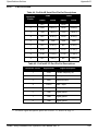
type is given in the table below.
Table 4: Voltage Input Ranges for GPSCards
GPSCard
Power Input Range
OEM4-G2L
+3.3 ± 0.15 VDC
OEM4-G2
+4.5 to +18 VDC
All members of the OEM4 family receivers are designed to prevent internal damage when subjected
to a reverse polarity power connection. The OEM4-G2 also provides protection from short over
28
OEM4 Family Installation and Operation User Manual Rev 16
Installation and Set Up
Chapter 3
voltage events. It is recommended that appropriate fuses or current limiting be incorporated as a safety
precaution on all power lines used. Use a sufficient gauge of wire to ensure that the voltage at the
connector is within the GPSCard’s requirements.
3.1.3.2
ProPak-G2plus, ProPak-LBplus or FlexPak Enclosures
The ProPak-G2plus, ProPak-LBplus and FlexPak enclosures are supplied with a 12V power adapter
with a built-in slow-blow fuse for use with a standard 12 VDC power outlet. NovAtel’s Aircraft
Power Conditioner can also be used to provide further protection for your receiver.
If a different supply is desired, the table below provides the input range required as well as the type of
connector required to mate with the receiver’s power connector. The supply should be capable of 5 W.
Table 5: Power Requirements for Enclosures
Enclosure
Power Cable Connector Required
Power Input Range
FlexPak
3-pin Deutsch socket connectora labelled
+6 to +18 VDC
ProPak-G2plus
4-pin LEMO socket connectora labelled PWR
+7 to +18 VDC b
ProPak-LBplus
2-pin Switchcraft socket connectora labelled
+7 to +15 VDC
a. See Appendix C, Replacement Parts starting on Page 153 for connector part numbers.
b. The power input range becomes +9 to + 18 VDC when an IMU device is connected. To
operate a complete SPAN system requires +12 to +18 VDC. If applicable, see the SPAN
Technology User Manual for more information.
3.2
Installation Overview
Once you have selected the appropriate equipment, complete the following steps to set up and begin
using your NovAtel GPS receiver.
1.
2.
3.
4.
5.
If your receiver has been provided as a GPSCard without an enclosure, install the card in an
enclosure with a wiring harness, as described in Section 3.2.1 on Page 30.
Mount the GPS antenna to a secure, stable structure, as described in Section 3.2.2 on Page 33.
Connect the GPS antenna to the receiver using an antenna RF cable, using the information given
in Section 3.2.3 on Page 33.
Apply power to the receiver, as described in Section 3.2.4 on Page 34.
Connect the receiver to a PC or other data communications equipment by following the
information given in Section 3.2.5 on Page 34.
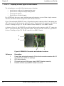
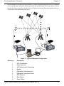
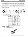
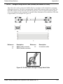
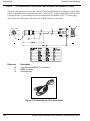
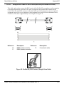
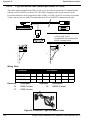
Figure 8 on the next page shows a typical set up for an enclosed receiver.
OEM4 Family Installation and Operation User Manual Rev 16
29
Chapter 3
Installation and Set Up
1
2
4 5
7
6
Figure 8: Typical Receiver Installation
Reference
1
2
3
4
5
6
7
3.2.1
Description
Receiver
GPSAntenna Model 702 or 701
RF Antenna Cable
12V Power Adapter Cable
Optional AC Adapter or Aircraft Power Conditioner
Null Modem Data Cable
Data Communications Equipment
Installing a GPSCard in a Wiring Harness and Enclosure
To install a GPSCard, begin with the following:
1.
2.
3.
30
Ensure you are taking the necessary precautions against ESD, as described in Section 3.2.1.1 on
Page 31.
Mount the GPSCard in a secure enclosure to reduce environmental exposure and RF
interference, as described in Section 3.2.1.2 on Page 31.
Prepare a wiring harness to interface to the receiver’s data, status, and power signals using the
information given in Section 3.2.1.3 on Page 32.
OEM4 Family Installation and Operation User Manual Rev 16
Installation and Set Up
3.2.1.1
Chapter 3
Electrostatic Discharge (ESD) Precautions
Electrostatic discharge is a leading cause of failure of electronic equipment components and printed
circuit boards containing ESD-sensitive devices and components. It is imperative that ESD
precautions be followed when handling or installing a GPSCard. Refer to the Anti-Static Practices
section of the GPS+ Reference Manual for more information on ESD precautions.
Leave the GPSCard in its static-shielding bag or clamshell when not connected in its normal operating
environment. When removing the GPSCard from the ESD protection, follow accepted standard antistatic practices. Failure to do so may cause damage to the GPSCard.
When you remove the GPSCard from the original packing box, it is recommended that you save the
box and ESD protection for future storage or shipment purposes.
CAUTION
Remember:
•
•
•
•
•
3.2.1.2
Always wear a properly grounded anti-static wrist strap when handling the GPSCard.
Always hold the GPSCard by its corners or the RF shield, and avoid direct contact with
any of the components.
Do not let the GPSCard come in contact with clothing at any time because the grounding
strap cannot dissipate static charges from fabrics.
Failure to follow accepted ESD handling practices could cause damage to the GPSCard.
Warranty may be voided if equipment is damaged by ESD.
Mounting the Printed Circuit Board
The OEM4 family GPSCards are OEM products and therefore the printed circuit board is provided
without a housing structure. This allows flexibility in creating a mounting environment to suit
particular product and marketing requirements. The mounting and enclosure should provide the
following:
•
•
•
•
•
mounting of external connectors
protection from hostile physical environments (for example, rain, snow, sand, salt, water,
extreme temperatures)
electromagnetic shielding to protect from hostile RF environments (for example, nearby
transmitters)
electromagnetic shielding so that the final product itself conforms to RF emissions
specifications
protection from ESD (refer to the Anti-Static Practices section of the GPS+ Reference
Manual)
The GPSCard can be held in place by screws. Please see Appendix A, Technical Specifications starting
on Page 115 for mechanical drawings.
OEM4 Family Installation and Operation User Manual Rev 16
31
Chapter 3
3.2.1.3
Installation and Set Up
Preparing the Data, Signal & Power Harness
The wiring harness serves the following interconnect functions:
•
•
•
•
provide access to the serial communications ports
provide access to input and output timing strobes
provide power input(s)
provide access to control signals
For all GPSCards, the power, status, and data inputs and outputs are accessed from a single connector.
Therefore, the harness must be designed to mate with this connector.
Figure 9 shows that the OEM4-G2L uses a 24-pin dual-row male connector with 0.5 mm square pins
and 2 mm spacing for the data, power, and status signals. The pin out for this connector is specified in
Section A.2 starting on Page 116. The RF connector on the OEM4-G2L is an MMCX female.
As shown in Figure 10, the OEM4-G2 uses a 40-pin dual-row male connector with 0.25” square pins
and 0.1” spacing for the data, power, and status signals. The pin out for this connector is specified in
Section A.3 starting on Page 120. The RF connector is an MMCX female.
4
3
1
2
Figure 9: OEM4-G2L Connector and Indicator Locations
.Reference
1
2
3
4
32
Description
Power, data, and signal connector (24 pin dual row male connector with 0.5
mm square pins and 2 mm spacing)
LED status indicator
RF signal input and LNA power output (MMCX female connector)
External oscillator input (MMCX female connector)
OEM4 Family Installation and Operation User Manual Rev 16
Installation and Set Up
Chapter 3
4
3
2
1
Figure 10: OEM4-G2 Connector and Indicator Locations
.Reference
1
2
3
4
3.2.2
Description
Power, data, and signal connector (40 pin dual row male connector with
0.025” square pins and 0.1” spacing)
LED status indicator
RF signal input and LNA power output (MMCX female connector)
External oscillator input (MMCX female connector)
Mounting the GPS Antenna
Once the GPSCard is installed in a wiring harness and enclosure, the antenna to be used with the
receiver must be mounted. The GPS receiver has been designed to operate with any of the NovAtel
single-frequency or dual-frequency GPS antenna models. See Section 3.1.1 on Page 27 for more
information.
When installing the antenna system:
•
•
3.2.3
Choose an antenna location that has a clear view of the sky so that each satellite above the
horizon can be tracked without obstruction. (Refer to the Multipath section in the GPS+
Reference Manual).
Mount the antenna on a secure, stable structure capable of safe operation in the specific
environment.
Connecting the Antenna to the Receiver
Connect the antenna to the receiver using high-quality coaxial cable, as discussed in Section 3.1.2 on
Page 27.
The ProPak-G2plus, ProPak-LBplus and FlexPak enclosures provide a TNC female connector, which
can be connected to the antenna directly with any of NovAtel’s coaxial cables. For the GPSCards, an
interconnect adapter cable is required to convert the TNC male end of the coaxial cable to the card’s
MMCX female RF input connector. The location of the RF connector for each of the GPSCards is
shown in Figure 9 and Figure 10.
OEM4 Family Installation and Operation User Manual Rev 16
33
Chapter 3
3.2.4
Installation and Set Up
Applying Power to the Receiver
Connect the power supply, set to the voltage given in Section 3.1.3 on Page 28, to the wiring harness
created previously.
For a ProPak-G2plus, ProPak-LBplus or FlexPak enclosure, connect the power supply to the port
described in Table 5, Power Requirements for Enclosures on Page 29.
3.2.5
Connecting Data Communications Equipment
In order to communicate with the receiver by sending commands and obtaining logs, a connection to
some form of data communications equipment is required. The default configuration available for
each of the receiver types is given in the table below. However, if desired, on some of the receivers,
the serial ports can be factory configured for either RS232, RS422, or LVTTL operation. Consult
NovAtel Customer Service for more details on factory configuration. See Appendix A, Technical
Specifications starting on Page 115 for data connection details.
Table 6: Default Serial Port Configurations
Receiver
COM1
COM2
COM3
OEM4-G2L
RS-232
LVTTL
Not available
OEM4-G2
User-selectable as RS-232 or RS-422. See Section 3.2.5.1 on Page 35 for more information.
RS-232
LVTTL
FlexPak a
RS-232
RS-232 / RS-422
Not available
ProPak-G2plus
RS-232
RS-232
RS-232
ProPak-LBplus
RS-232
RS-232
RS-232
a. If Pin# 1 on the Deutsch connector is grounded, the COM2 communications mode
is set to RS-422.
Each port may support some, or all, of the following signals:
•
•
•
•
•
•
Data Terminal Ready (DTR)
Clear To Send (CTS)
Transmitted Data (TXD)
Request To Send (RTS)
Received Data (RXD)
Data Carrier Detect (DCD)
On many of the receivers, extra control lines are provided on COM2 for use with modems or other
differential correction data links.
The ProPak-G2plus, ProPak-LBplus and FlexPak enclosures are Data Terminal Equipment (DTE) so
that TXD, RTS and DTR are outputs while RXD, CTS and DCD are inputs. A null modem cable is
required to connect to another DTE like a terminal or a PC.
34
OEM4 Family Installation and Operation User Manual Rev 16
Installation and Set Up
Chapter 3
The port settings (bit rate, parity, and so on) are software-configurable. These are further described in
Chapter 4, Operation on Page 40. See Appendix A, Technical Specifications starting on Page 115 for
further information on data communications characteristics.
3.2.5.1
User-Selectable Port Configuration (OEM4-G2 Only)
The OEM4-G2 offers a user-selectable configuration for the COM1 port. The configuration is selected
using the USERIO1 pin. By default, RS-232 is selected as the USERIO1 input is set low by an
internal pull-down resistor. To select RS-422, upon startup apply 3.3 V to USERIO1 or tie it to pin 38
of the 40-pin connector.
Pin 38 on the 40-pin connector is usually an ERROR indicator, and during normal GPSCard
operations is set LOW, but for a few seconds during GPSCard initialization, immediately after
applying power to the GPSCard, this pin is set HIGH at 3.3 Volts. It drops to LOW a few seconds later
when the GPSCard has been fully booted up, around the time that the [COMx] prompt is output from
the GPSCard on all COM ports.
USERIO1 needs to be initialized HIGH during this initial boot-up phase in order to set up the COM1
port for RS-422 mode. Therefore, set pin 38 ERROR to HIGH to provide a convenient 3.3 V source
that is used to trigger the USERIO1 to set the COM1 port to RS-422 mode. See also Page 35 for note.
Your OEM4-G2 hardware revision must be 3.00 or later and you must be running firmware 2.110
or later in order to use this RS-422 feature on the COM1 port of the OEM4-G2 GPSCard.
3.3
Additional Features and Information
This section contains information on the additional features of the OEM4 family receivers, which may
affect the overall design of your receiver system.
3.3.1
Strobes
On many of the OEM4 family receivers, a set of inputs and outputs that provide status and
synchronization signals are given. These signals are referred to as strobes. As shown in Table 7 on
Page 36, not all strobe signals are provided on all receivers. However, for those products for which
strobes are available, you may want to design your installation to include support for these signals.
The OEM4-G2L provides 6 TTL-compatible I/O strobes, which can be located on the connector
shown in Figure 39, OEM4-G2L Board Dimensions on Page 116. The OEM4-G2 GPSCard has 9
TTL-compatible I/O strobe lines. See Figure 41, OEM4-G2 Board Dimensions on Page 120.
The ProPak-G2plus provides strobe signals at its I/O port, as described in Table 25 on Page 136.
Access to the ProPak-LBplus strobe signals is obtained through the COM1 port, which is labelled
. See Table 27 on Page 144 for more information on the ProPak-LBplus strobes.
Strobe signals include an input and several outputs as described below:
•
Mark Input (Event1, Event2)
A pulse on this input triggers certain logs to be
generated. (Refer to the MARKPOS and
MARKTIME logs and ONMARK trigger in Volume
OEM4 Family Installation and Operation User Manual Rev 16
35
Chapter 3
Installation and Set Up
2 of this manual set). For the OEM4-G2 and OEM4G2L, the polarity is configurable (refer to the
MARKCONTROL command in Volume 2 of this
manual set). The mark inputs have 10K pull up
resistors to 3.3 V and are falling edge triggered.
• Measure Output (MSR)
Falling edge is synchronized with internal GPS
measurements.
• Pulse Per Second Output (PPS)
A pulse for which the trailing edge is synchronized
with GPS time. For the OEM4-G2 and OEM4-G2L,
the polarity and period is configurable using the
PPSCONTROL command (refer to Volume 2 of this
manual set).
• Position Valid Output (PV)
High when good GPS position and time solution.
• Error Output (ERROR)
High when a receiver hardware failure is detected.
• LED Red Output (STATUS_RED)
Hardware failure when on or pulsing.
• LED Green Output (STATUS_GREEN) Normal operation when pulsing at 1 Hz.
• Variable Frequency (VARF)
Programmable output range from 0 to 20 MHz
(refer to FREQUENCYOUT in Volume 2 of this
manual set).
See Appendix A, Technical Specifications starting on Page 115, for further information on the strobe
signal characteristics.
Table 7: Available Strobe Signals on Receivers
Signal
EVENT1
EVENT2
MSR
PPS
PV
ERROR
STATUS
_RED
STATUS
_GREEN
VARF
OEM4-G2L
Pin 8
Pin 7
Not
Pin 4
available
Pin 10
Pin 9
Not
available
Not
available
Pin 3
OEM4-G2
Pin 11
Pin 31
Pin 32
Pin 2
Pin 38
Pin 13
Pin 28
Pin 9
FlexPak
Pin 4
Pin 6
Not
COM1/
Not
available COM2
available
port, Pin
10
COM1/
COM2
port, Pin
13
Not
available
Not
available
Not
available
I/O port,
pin 6
I/O port,
pin 3
I/O port,
pin 8
Not
available
Not
available
I/O port,
pin 1
Not
Not
Not
available available available
Not
available
Not
available
ProPak-G2plus I/O port,
pin 4
Not
ProPak-LBplus COM1
port, pin 2a available
Pin 7
I/O port,
pin 2
Not
COM1
available port, pin
1a
I/O port,
pin 5
a. The ProPak-LBplus COM1 port is RS-232 and also provides access to strobe signals.
36
OEM4 Family Installation and Operation User Manual Rev 16
Installation and Set Up
3.3.2
Chapter 3
USB (OEM4-G2/-G2L, FlexPak and ProPak-G2plus Only)
The OEM4-G2/-G2L and FlexPak receivers running firmware version 2.100 or higher, along with the
accompanying NovAtel USB drivers for Windows 2000 and Windows XP, provide three virtual serial
ports over a single USB connection using USB D(+) and USB D(-) signals. See Figure 40 on Page
119 and Figure 42 on Page 124 for pin-out information. The ProPak-G2plus, with 2.200 firmware or
higher, provides a USB connection through its COM1 port, see Table 24 on Page 136.
These three virtual serial ports, identified by the GPSCard as USB1, USB2, and USB3, are available
to existing Windows applications which use COM ports to communicate (for example,
HyperTerminal and GPSolution4). The NovAtel USB drivers assign COM port numbers sequentially
following any existing ports on the PC. For example, if a PC has COM1 and COM2 ports, the
NovAtel USB drivers will assign COM3 to USB1, COM4 to USB2, and COM5 to USB3.
The assignment of COM port numbers is tied to the USB port on the PC. This allows you to
switch receivers without Windows assigning new COM ports. However, if you connect the
receiver to a different USB port, Windows detects the receiver's presence on that USB port and
assigns three new COM port numbers.
The NovAtel USB Configuration Utility installed with the NovAtel USB drivers allows you to change
the COM port numbers assigned to the virtual serial ports. The USB drivers, along with installation
instructions, are available on the OEM4 Family CD by selecting USB Support from the main menu.
You can also check for updates to the drivers or release notes on our website at www.novatel.com.
3.3.3
Status Indicators
Many of the OEM4 family receivers have LED indicators that provide the status of the receiver. The
GPSCards have a single indicator, which is shown in Figure 9 on Page 32 for the OEM4-G2L, and
Figure 10 on Page 33 for the OEM4-G2. The LED blinks green on and off at approximately 1 Hz to
indicate normal operation. If the indicator is red, then the receiver is not working properly. The
operation of this indicator is further described in Section 8.6 on Page 108.
The FlexPak, ProPak-G2plus and ProPak-LBplus provide the status indicators shown in Tables 8 - 10.
Table 8: FlexPak Status Indicators
Indicator
Indicator Color
Green
Status
Data is being transmitted from COM1
COM1
Red
Green
Data is being received on COM1
Data is being transmitted from COM2
COM2
Red
Data is being received on COM2
Red
Hardware error.
ANT
PWR
Green
Valid position computed.
Red
The receiver is powered
OEM4 Family Installation and Operation User Manual Rev 16
37
Chapter 3
Installation and Set Up
Table 9: ProPak-G2plus Status Indicators
Indicator
Indicator Color
Green
Status
Data is being transmitted from COM1
COM1
Red
Green
Data is being received on COM1
Data is being transmitted from COM2
COM2
Red
Green
Data is being received on COM2
Data is being transmitted from COM3
AUX
PWR
Red
Data is being received on COM3
Red
The receiver is powered
Table 10: ProPak-LBplus Status Indicators
Indicator
Indicator Color
Red
3.3.4
Status
Hardware error.
Green
Valid position computed.
Red
The receiver is powered.
External Oscillator (OEM4-G2/-G2L and ProPak-G2plus Only)
For certain applications requiring greater precision than what is possible using the on-board 20 MHz,
voltage-controlled, temperature-compensated crystal oscillator (VCTCXO), you may wish to connect
the OEM4-G2L or OEM4-G2 to an external, high-stability oscillator. The external oscillator can be
either 5 MHz or 10 MHz.
Installation consists of connecting a cable from the external oscillator to the receiver’s external
oscillator input connector.
For the ProPak-G2plus, with firmware 2.200 or higher, the BNC external oscillator port, labeled OSC,
is used. See Figure 5, ProPak-G2plus Rear Panel on Page 21.
For the OEM4-G2L and OEM4-G2, an MMCX female connector is used, as shown in Figure 9 on
Page 32 and Figure 10 on Page 33, respectively. The receiver does not have to be powered down
during this procedure. If you are handling the OEM4-G2 or OEM4-G2L directly, anti-static practices
must be observed.
Once the external oscillator has been installed, the EXTERNALCLOCK command must be issued to
define the clock model (for example, cesium, rubidium or ovenized crystal). If the input clock rate is 5
MHz, the EXTERNALCLOCK command must be issued to change the 10 MHz default rate. For
more information on this command, please refer to Volume 2 of this manual set.
38
OEM4 Family Installation and Operation User Manual Rev 16
Installation and Set Up
3.3.5
Chapter 3
External Antenna LNA Power (OEM4-G2 Only)
For the OEM4-G2 it is possible to supply power to the LNA of an active antenna either from the
antenna port of the GPSCard itself or from an external source. The internal antenna power supply of
the GPSCards can produce +4.75 to +5.10 VDC at up to 100 mA. This meets the needs of any of
NovAtel’s dual-frequency GPS antennas, so, in most cases, an additional LNA power supply is not
required.
If a different antenna is used whose LNA requires voltage capacity beyond what the receiver can
produce, then the external LNA power option must be utilized. This simply requires setting a voltage
supply between +12 and +30 VDC, 100 mA maximum, and connecting it to pin 40 of the 40-pin
connector on the OEM4-G2. See also Appendix A, RF Input / LNA Power Output on Page 117.
In either case, the LNA power is fed to the antenna through the same coaxial cable used for the RF
signals. The internal LNA power source should be disabled using the ANTENNAPOWER command.
Refer to Volume 2 of this manual set for more information on this command.
External LNA power is not possible with an OEM4-G2L, ProPak-G2plus, ProPak-LBplus or FlexPak
receiver.
CAUTION
No warranty is made that the receiver will meet its performance specifications if a non-NovAtel
antenna is used.
3.3.6
Mounting Bracket (ProPak-G2plus and ProPak-LBplus Only)
Along with the ProPak-G2plus and ProPak-LBplus enclosures, mounting kits have been provided to
facilitate mounting the receivers to a surface. This section provides information on how to mount the
receivers.
The mounting kits are not designed for use in high-dynamics or high-vibration environments.
Contact NovAtel Customer Service if your application requires the ProPak-G2plus or ProPakLBplus to be mounted in these types of environments.
3.3.6.1
ProPak-G2plus and ProPak-LBplus
To install the mounting bracket provided with the ProPak-G2plus and ProPak-LBplus, refer to the
instructions provided with the mounting kit. Page 143 provides the dimension information for the
bracket.
OEM4 Family Installation and Operation User Manual Rev 16
39
Chapter 4
Operation
Before operating the receiver for the first time, ensure that you have followed the installation
instructions in Chapter 3, Installation and Set Up on Page 27. The following instructions are based on
a configuration such as that shown in Figure 11, Typical Operational Configuration. It is assumed that
a personal computer is used during the initial operation and testing for greater ease and versatility.
16
3
5
6
4
1
11
7
14
8
12
9
15
10
13
2
Figure 11: Typical Operational Configuration
Reference
40
Description
Reference
Description
1
GPSCard
9
External Oscillator Signal
2
OEM Enclosure
10
Power
3
Antenna Model 701,702,532, 533
11
Radio
4
GPS Signal
12
Data Logger or Rover Stn.
5
COM1 Signal
13
External DC Power Source
6
COM2 Signal
14
USB Device
7
USB Signal
15
External Oscillator
8
COM3 Signal
16
PC or Base Station
OEM4 Family Installation and Operation User Manual Rev 16
Operation
4.1
Chapter 4
Communications with the Receiver
Communication with the receiver is straightforward, and consists of issuing commands through the
communication ports from an external serial communications device. This could be either a terminal
or an IBM-compatible PC that is directly connected to the receiver serial port using a null modem
cable. If you are using an RTK radio it connects to the receiver’s COM port by means of the radio
serial cable supplied with the receiver. For information about commands and logs that are useful for
basic operation of the receiver, refer to Volume 2, Command and Log Reference, of this manual set.
4.1.1
Serial Port Default Settings
The receiver communicates with your PC or terminal via a serial port. For communication to occur,
both the receiver and the operator interface have to be configured properly. The receiver’s COM1,
COM2 and COM3 default port settings are as follows:
•
9600 bps, no parity, 8 data bits, 1 stop bit, no handshaking, echo off
Changing the default settings requires using the COM command, which is described in Volume 2 of
this manual set. It is recommended that you become thoroughly familiar with the commands and logs
detailed in Volume 2 to ensure maximum utilization of the receiver’s capabilities.
The data transfer rate you choose will determine how fast information is transmitted. Take for
example a log whose message byte count is 96. The default port settings will allow 10 bits/byte. It will
therefore take 960 bits per message. To get 10 messages per second then will require 9600 bps. Please
also remember that even if you set the bps to 9600 the actual data transfer rate will be less and
depends on the number of satellites being tracked, filters in use, and idle time. It is therefore suggested
that you leave yourself a margin when choosing a data rate.
CAUTION:
4.1.2
Although the receiver can operate at data transfer rates as low as 300 bps, this is
not desirable. For example, if several data logs are active (that is, a significant
amount of information needs to be transmitted every second) but the bit rate is set
too low, data will overflow the serial port buffers, cause an error condition in the
receiver status and result in lost data.
Communicating Using a Remote Terminal
One method of communicating with the receiver is through a remote terminal. The receiver has been
pre-wired to allow proper RS232 interface with your data terminal. To communicate with the terminal
the receiver only requires the RX, TX, and GND lines to be used. Handshaking is not required,
although it can optionally be used. Ensure the terminal’s communications set-up matches the
receiver’s RS232 protocol.
4.1.3
Communicating Using a Personal Computer
An IBM-compatible PC can be set up to emulate a remote terminal as well as provide the added
flexibility of creating multiple-command batch files and data logging storage files. Any standard
communications software package that emulates a terminal can be used to establish bidirectional
communications with the receiver. No particular terminal type is assured. All data is sent as raw
OEM4 Family Installation and Operation User Manual Rev 16
41
Chapter 4
Operation
characters.
You can create command batch files using any text editor; these can then be directed to the serial port
that is connected to the receiver using a communications software package. This is discussed later in
this chapter.
4.2
Getting Started
Included with your receiver are NovAtel’s GPSolution and Convert programs. GPSolution is a
Microsoft Windows-based graphical user interface which allows you to access the receiver's many
features without struggling with communications protocol or writing special software. The Convert
utility is a Windows-based utility that allows you to convert between file formats, and strips unwanted
records for data file compilation. See Chapter 7, PC Software and Firmware on Page 88 for more
information on the GPSolution and Convert programs.
4.2.1
Starting the Receiver
The receiver’s software resides in read-only memory. As such, the unit “self-boots” when turned on
and undergoes a complete self-test. If an error condition is detected during a self-test, the self-test
status word would change; this self-test status word can be viewed in the header of any data output
log. Refer to the chapter on Messages in Volume 2 of this manual set for header information. If a
persistent error develops, please contact your local NovAtel dealer first. If the problem is still
unresolved, please contact NovAtel directly through any of the methods in the Customer Service
section at the beginning of this manual on Page 12.
When the receiver is first turned on, no activity information is transmitted from the COM ports except
for the port prompt. The external data communications equipment screen will display one of these
three messages:
[COM1]
if connected to COM1 port,
[COM2]
if connected to COM2 port,
or
[COM3]
if connected to COM3 port
Any of these prompts indicate that the receiver is ready and waiting for command input.
Commands are typed at the interfacing terminal’s keyboard, and executed after issuing a carriage
return command which is usually the same as pressing the terminal’s <Enter> key.
An example of a response to an input command is the FIX POSITION command. It can be entered:
[COM2]FIX POSITION 51.11635 -114.0383 1048.2[Carriage Return]
<OK
The above example illustrates command input to the receiver’s COM2 port which sets the position of
the base station receiver in differential operation. Confirmation that the command was actually
accepted is the appearance of <OK.
If a command is incorrectly entered, the receiver will respond with “<Invalid Message ID” (or a more
detailed error message).
42
OEM4 Family Installation and Operation User Manual Rev 16
Operation
Chapter 4
For more information on the various commands and logs please refer to the user manual entitled
Volume 2, Command and Log Reference, of this manual set.
WARNING:
4.2.2
Ensure the Control Panel’s Power Settings on your PC are not set to go into
Hibernate or Standby modes. Data will be lost if one of these modes occurs during
a logging session.
Remote Terminal, PC and GPS Receiver
In addition to GPSolution, you can use a a terminal program. Examples of how to use a DOS or
Microsoft terminal window follows. For this example, consider a situation where a PC’s
appropriately-configured COM1 port is connected to the receiver’s COM1 port, and where a remote
terminal is connected to the receiver’s COM2 port.
4.2.2.1
DOS
One way to initiate multiple commands and logging from the receiver is to create DOS boot-up
command files relating to specific functions. This will save time when you want to duplicate test
situations and minimize set-up time. Any convenient text editor can be used to create command text
files.
1. Open a text editor on the PC and type in the command strings to be sent to the receiver upon start
up. For example:
log
log
log
log
log
log
log
com2
com2
com2
com2
com2
com2
com2
bestposa ontime 1
rangea ontime 1
rxstatusa onchanged
psrdopa onchanged
gpsephema onchanged
almanaca onchanged
rxconfiga once
1.
Ensure you have used a carriage return (hit the enter key) after typing the last line.
2.
If you wish these to become part of the permanent configuration of the card, rather than just
using them on boot-up, enter the SAVECONFIG command as the last line.
2. Save this with a convenient file name (for example, C:\GPS\BOOT1.TXT) and exit the text editor.
3. Use the DOS copy command to direct the contents of the BOOT1.TXT file to the PC’s COM1
port:
C:\GPS>copy boot1.txt com1
1 file(s) copied
C:\GPS>
4. The receiver is now initialized with the contents of the BOOT1.TXT command file, and logging is
directed from the receiver’s COM2 port to the remote terminal.
OEM4 Family Installation and Operation User Manual Rev 16
43
Chapter 4
4.2.2.2
Operation
Microsoft Windows
As any text editor or communications program can be used for these purposes, the use of Windows 95
is described only as an illustration. The following example shows how Windows 95 accessory
programs Notepad and HyperTerminal can be used to create a boot-file on a PC, and send it to the
OEM4. It is assumed that the PC’s serial port COM1 is connected to the receiver’s COM1 port, and
that a remote terminal is connected to the receiver’s COM2 port.
1.
4.3
Open Notepad and type in the command strings to be sent to the receiver upon start up. For
example:
log com2 bestposa ontime 1
log com2 rangea ontime 1
log com2 rxstatusa onchanged
log com2 psrdopa onchanged
log com2 gpsephema onchanged
log com2 almanaca onchanged
log com2 rxconfiga once
1.
Ensure you have used a carriage return (hit the enter key) after typing the last line.
2.
If you wish these to become part of the permanent configuration of the card, rather than just
using them on boot-up, enter the SAVECONFIG command as the last line.
2.
Save this with a convenient file name (for example, C:\GPS\BOOT.TXT) and exit Notepad.
3.
Ensure that the HyperTerminal settings are correctly set up to match the settings with the
receiver’s communications protocol. These settings can be saved (for example,
C:\GPS\OEMSETUP.HT) for use in future sessions. You may wish to use XON / XOFF
handshaking to help prevent loss of data.
4.
From the Transfer menu, use the Send text file selection to locate this file to be sent to the
receiver. Once you double-click on the file or select Open, HyperTerminal will send the file to the
receiver.
Transmitting and Receiving Corrections
Corrections are transmitted from a base station to a rover station to reduce or eliminate errors
introduced by system biases, as described in Section 6.1.1, GPS System Errors on Page 65. In most
cases you will need to provide a data link between the base station and rover station (two NovAtel
receivers) in order to receive corrections. Exceptions are the SBAS and L-Band capable receivers.
However, if you wish to use other types of corrections for these receivers, a data link must be
provided. Generally a link capable of data throughput at a rate of 2400 bits per second or higher is
sufficient for the examples shown below.
Next you need to pre-configure the base and rover site receivers before the units are used in your
application. At the base station, enter the following commands:
interfacemode port rx_type tx_type
fix position latitude longitude height
log port message [trigger [period]]
44
OEM4 Family Installation and Operation User Manual Rev 16
Operation
Chapter 4
For example:
RTCA
interfacemode com2 none rtca
fix position 51.11358042 -114.04358013 1059.4105
log com2 rtcaobs ontime 2
log com2 rtcaref ontime 10
log com2 rtca1 ontime 10 3
log com2 rtcaephem ontime 10 7
interfacemode com2 none rtcm
fix position 51.11358042 -114.04358013 1059.4105
log com2 rtcm3 ontime 10
log com2 rtcm22 ontime 10
log com2 rtcm1819 ontime 2
log com2 rtcm1 ontime 10 5
RTCM
RTCMV3
interfacemode com2 none rtcmv3
fix position 51.11358042 -114.04358013 1059.4105
log com2 rtcm1006 ontime 3
log com2 rtcm1002 ontime 10
CMR
interfacemode com2 none cmr
fix position 51.11358042 -114.04358013 1059.4105
log com2 cmrobs ontime 2
log com2 cmrref ontime 10
log com2 cmrdesc ontime 10 5
At the rover station, enter:
interfacemode port rx_type tx_type
For example:
RTCA
RTCM
RTCMV3
CMR
interfacemode
interfacemode
interfacemode
interfacemode
com2
com2
com2
com2
rtca none
rtcm none
rtcmv3 none
cmr none
For compatibility with other GPS receivers, and to minimize message size, it is recommended that
you use the standard form of RTCA, RTCM or CMR corrections as shown in the examples above.
This requires using the INTERFACEMODE command, refer to Volume 2 of this manual set, to
dedicate one direction of a serial port to only that message type. Once the INTERFACEMODE
command is used to change the mode from the default, NOVATEL, you can no longer use NovAtel
format messages.
If you wish to mix NovAtel format messages and RTCA, RTCM or CMR messages on the same port,
you can leave the INTERFACEMODE set to NOVATEL and log out variants of the standard
messages with a NovAtel header. ASCII or binary variants can be requested by simply appending an
"A" or "B" to the standard message name. For example on the base station:
interfacemode com2 novatel novatel
fix position 51.11358042 -114.04358013 1059.4105
log com2 rtcm1b ontime 2
At the rover station you can leave the INTERFACEMODE default settings (interfacemode com2
OEM4 Family Installation and Operation User Manual Rev 16
45
Chapter 4
Operation
novatel novatel). The rover receiver will recognize the default and use the corrections it receives with
a NovAtel header.
The PSRDIFFSOURCE and RTKSOURCE commands set the station ID values which identify the
base stations from which to accept pseudorange or RTK corrections respectively. They are useful
commands when the rover station is receiving corrections from multiple base stations. With the
PSRDIFFSOURCE command, all types may revert to SBAS if enabled using the SBASCONTROL
command. Refer to Volume 2 of this manual set for more details on these commands. See Section
6.2,Satellite-Based Augmentation System (SBAS) on Page 66 for more information on SBAS.
At the base station it is also possible to log out the contents of the standard corrections in a form that is
easier to read or process. These larger variants have the correction fields broken out into standard
types within the log, rather than compressed into bit fields. This can be useful if you wish to modify
the format of the corrections for a non-standard application, or if you wish to look at the corrections
for system debugging purposes. These variants have "DATA" as part of their names (for example,
RTCADATA1, RTCMDATA1, CMRDATAOBS, and more). Refer to Volume 2 of this manual set for
details.
Chapter 5, Message Formats on Page 51 describes the various message formats in more detail.
4.4
Enabling SBAS Positioning
OEM4 family receivers with a W, WAAS, MSAS or EGNOS in their model name are capable of
SBAS positioning. This positioning mode is enabled using the SBASCONTROL command. EGNOS at
one time used the IGNOREZERO test mode. At the time of printing, ZEROTOTWO is the correct
setting for all SBAS, including EGNOS, running in test mode. On a simulator, you may want to leave
this parameter off or specify NONE explicitly. As a result, the following commands are typically used
to enable WAAS and EGNOS modes, respectively:
SBASCONTROL WAAS ENABLE 0 ZEROTOTWO
SBASCONTROL EGNOS ENABLE 120 ZEROTOTWO
See Section 6.2, Satellite-Based Augmentation System (SBAS) on Page 66 for more information.
4.5
Enabling L-Band Positioning (ProPak-LBplus Only)
L-Band equipped receivers allow you to achieve sub-meter accuracy. In order to use this positioning
mode, you must enable L-band tracking to the Canada-Wide Differential Global Positioning System
(CDGPS) or OmniSTAR signal. A subscription to OmniSTAR is required to use the OmniSTAR
service. The CDGPS signal is free and available without subscription.
To obtain an OmniSTAR subscription, contact them at 1-800-338-9178 or 713-785-5850. If you
contact OmniSTAR, you will be asked to provide the receiver’s OmniSTAR serial number (which is
different from the NovAtel serial number). To obtain the OmniSTAR serial number, enter the
following command in a terminal window or the Console window in GPSolution:
LOG LBANDINFO
The log that is generated will display the L-Band serial number in the fifth field following the log
header. It is a six digit number in the range 700000 to 799999. This log also provides the status of
your subscription. Refer to Volume 2 of this manual set for more information.
46
OEM4 Family Installation and Operation User Manual Rev 16
Operation
Chapter 4
In order to activate an OmniSTAR subscription, the receiver must be powered and tracking an L-Band
satellite. When advised by OmniSTAR of the appropriate satellite frequency and data link rate for
your location, use the ASSIGNLBAND command to configure your receiver. The CDGPS frequencies
are on Page 74 and these can also be used with the ASSIGNLBAND command. As an example, if your
frequency is 1,525,000 kHz and your data link speed is 1200 baud, enter the following:
ASSIGNLBAND USER 1525000 1200
To confirm you are tracking an L-Band signal, log the L-Band status information by entering the
following command:
LOG LBANDSTAT
For example, if you are receiving CDGPS, the fifth field after the header should be 00c2:
LBANDSTAT COM1 0 43.5 FINESTEERING 1295 149951.671 00000000
976f 34461
<1547546977 46.18 4541.0 0.00 00c2 00f0 0 0 0 8070 0001 0 0 0
Please refer to Volume 2 of this manual set for more details.
4.6
Pass-Through Logging
The pass-through logging feature enables the receiver to redirect any ASCII or binary data that is
input at a specified COM port or, if available, USB port to any specified receiver COM or USB port.
This capability, in conjunction with the SEND command, can allow the receiver to perform bidirectional communications with other devices such as a modem, terminal, or another receiver.
There are several pass-through logs PASSCOM1, PASSCOM2, PASSCOM3, PASSXCOM1,
PASSXCOM2 and PASSAUX, available on OEM4 family receivers for logging through serial ports.
The AUX port is available on OEM4-G2-based products (hardware Rev. 3 and higher) and DL-4
products. For the OEM4-G2 and OEM4-G2L, there are an additional three, PASSUSB1, PASSUSB2,
and PASSUSB3, offered. Refer to Volume 2 of this manual set for individual logs and commands.
A pass-through log is initiated the same as any other log, that is, LOG [to-port] [data-type] [trigger].
However, pass-through can be more clearly specified as: LOG [to-port] [from-port-AB] [onchanged].
Now, the [from-port-AB] field designates the port which accepts data (that is, COM1, COM2, COM3,
AUX, USB1, USB2, or USB3) as well as the format in which the data will be logged by the [to-port]
(A for ASCII or B for Binary).
When the [from-port-AB] field is suffixed with an [A], all data received by that port will be redirected
to the [to-port] in ASCII format and will log according to standard NovAtel ASCII format. Therefore,
all incoming ASCII data will be redirected and output as ASCII data. However, any binary data
received will be converted to a form of ASCII hexadecimal before it is logged.
When the [from-port-AB] field is suffixed with a [B], all data received by that port will be redirected
to the [to-port] exactly as it is received. The log header and time-tag adhere to standard NovAtel
Binary format followed by the pass-through data as it was received (ASCII or binary).
Pass-through logs are best utilized by setting the [trigger] field as onchanged or onnew. If the data
being injected is ASCII then the data will be grouped together with the following rules:
• blocks of 80 characters
• any block of characters ending in a <CR>
• any block of characters ending in a <LF>
OEM4 Family Installation and Operation User Manual Rev 16
47
Chapter 4
Operation
• any block remaining in the receiver code when a timeout occurs
If the data being injected is binary then the data will be grouped as follows:
• blocks of 80 bytes
• any block remaining in the receiver code when a timeout occurs
If a binary value is encountered in an ASCII output, then the byte is output as a hexadecimal byte
preceded by a backslash and an x. For example 0A is output as \x0A. An actual ‘\’ in the data is output
as \\. The output counts as one pass-through byte although it is four characters.
The first character of each pass-through record is time tagged in GPS weeks and seconds.
For example, you could connect two OEM4 family receivers together via their COM1 ports such as in
Figure 12 on Page 48, a rover station to base station scenario. If the rover station were logging
BESTPOSA data to the base station, it would be possible to use the pass-through logs to pass through
the received BESTPOSA data to a disk file (let's call it DISKFILE.log) at the base station host PC
hard disk.
BESTPOSA data log...
5
1
1
3
FIX POSITION (lat, lon, ht)
INTERFACEMODE COM1 none none off
log com1 BESTPOSA ontime 5
4
2
2
INTERFACEMODE com1 none none off
log com1 PASSCOM1A onchanged
6
7
8
Reference
Description
Reference
Description
1
To COM1
5
Data link
2
To COM2
6
Serial cables
3
Rover receiver
7
Pocket PC - rover
4
Base receiver
8
Laptop PC - base
Figure 12: Pass-Through Log Data
48
OEM4 Family Installation and Operation User Manual Rev 16
Operation
Chapter 4
Under default conditions the two receivers will "chatter" back and forth with the Invalid Command
Option message (due to the command interpreter in each receiver not recognizing the command
prompts of the other receiver). This chattering will in turn cause the accepting receiver to transmit
new pass-through logs with the response data from the other receiver. To avoid this chattering
problem, use the INTERFACEMODE command on the accepting port to disable error reporting from
the receiving port command interpreter.
If the accepting port's error reporting is disabled by INTERFACEMODE, the BESTPOSA data record
would pass through creating two records.
The reason that two records are logged from the accepting receiver is because the first record was
initiated by receipt of the BESTPOSA log's first terminator <CR>. Then the second record followed
in response to the BESTPOSA log's second terminator <LF>.
Note that the time interval between the first character received and the terminating <LF> can be
calculated by differencing the two GPS time tags. This pass-through feature is useful for time tagging
the arrival of external messages. These messages could be any user-related data. If the user is using
this feature for tagging external events, it is recommended that the command interpreter be disabled so
that the receiver does not respond to the messages. Refer to the INTERFACEMODE command in
Volume 2 of this manual set.
If the BESTPOSB binary log data were input to the accepting port (log com2 passcom1a onchanged),
the BESTPOSB binary data at the accepting port is converted to a variation of ASCII hexadecimal
before it is passed through to COM2 port for logging.
4.7
Transferring Time Between Receivers
The following are clock steering states:
Fine
An OEM4 family receiver that is tracking satellites, and has a receiver clock state of
FINE or FINESTEERING.
Cold Clock
An OEM4 family receiver that needs to have its clock synchronized with the Fine
receiver. It may have any clock state including UNKNOWN.
Warm Clock An OEM4 family receiver that has its clock adjusted to better then 500 ms. Refer to
the TIME log in Volume 2 of this manual set to view the clock offset.
The sections that follow are procedures for transferring time from a Fine receiver to a Cold or Warm
Clock receiver.
4.7.1
Procedures
To transfer COARSE time (<10 ms) from a Fine to a Cold Clock GPS receiver:
1.
Connect a COM port from the Fine to the Cold Clock (for example, COM2 on the Fine to
COM3 on the Cold Clock). Configure both ports to the same baud rate and handshaking
configurations.
2.
Issue this command to the Fine receiver:
log com2 timesyncb ontime 1
3.
Issue this command to the Cold Clock receiver: adjust1pps time
OEM4 Family Installation and Operation User Manual Rev 16
49
Chapter 4
Operation
When the Cold Clock receiver receives the TIMESYNC log, it sets its clock allowing for a 100 ms
transfer delay.
To transfer FINE time (<50 ns) from a Fine GPS to a Cold Clock GPS receiver:
1.
Connect a COM port from the Fine to the Cold Clock receiver (for example, COM2 on the
Fine to COM3 on the Cold Clock). Configure both ports to the same baud rate and
handshaking configurations.
2.
Issue this command to the Fine receiver:
log com2 timesyncb ontime 1
3.
Connect the 1PPS signal of the Fine to the mark 1 input (Event1) of the Cold Clock receiver.
4.
Issue this command to the Cold Clock receiver:
adjust1pps markwithtime
When the Cold Clock receiver receives the 1PPS "event" from the Fine receiver, it checks to see if it
has received a valid TIMESYNC log within 200 ms of the last 1PPS event. If so, it will set the Cold
Clock receiver clock to the time of the Fine receiver. See Figure 13, 1PPS Alignment below.
To transfer FINE time from a Fine to a Warm Clock GPS receiver:
1.
Connect the 1PPS signal of the Fine to the mark 1 input (Event1) of the Warm Clock receiver.
2.
Issue this command to the Warm Clock receiver:
adjust1pps mark
The phase of the Warm Clock receiver clock is adjusted by the fractional measurement of the Fine
receiver’s 1PPS mark input event. In other words, it will synchronize the Warm Clock receiver’s 1PPS
to the incoming 1PPS of the Fine receiver. It will NOT adjust the 1 second Time of Week (TOW)
counter or the receiver's Week Number. This procedure is used to make small corrections to the Warm
Clock receiver’s clock.
TIMESYNC
Fine
Receiver
RS232
Connected to
COM Input
On Warm
Clock Receiver
1PPS on
Fine Receiver TTL
Connected
to MK1I on
Warm Clock
Receiver
< 200 ms
1PPS IN
Figure 13: 1PPS Alignment
50
OEM4 Family Installation and Operation User Manual Rev 16
Chapter 5
Message Formats
The chapter discusses the various industry-standard message formats that can be used with your
NovAtel OEM4 family receiver, including RTCA, RTCM, RTCMV3, CMR, and NMEA. See Section
4.3,Transmitting and Receiving Corrections on Page 44 for more information on using these message
formats for differential operation.
5.1
RTCA-Format Messages
The RTCA (Radio Technical Commission for Aviation Services) Standard is being designed to
support Differential Global Navigation Satellite System (DGNSS) Special Category I (SCAT-I)
precision instrument approaches. The RTCA Standard is in a preliminary state. Described below is
NovAtel’s current support for this standard. It is based on “Minimum Aviation System Performance
Standards DGNSS Instrument Approach System: Special Category I (SCAT-I)” dated August 27,
1993 (RTCA/DO-217).
NovAtel has defined three proprietary RTCA Standard Type 71 binary-format messages, RTCAOBS,
RTCAREF and RTCAEPHEM for base station transmissions. These can be used with either single or
dual-frequency NovAtel receivers. The RTCA message format outperforms the RTCM format in the
following ways, among others:
•
•
•
a more efficient data structure (lower overhead)
better error detection
allowance for a longer message, if necessary
RTCAREF and RTCAOBS, respectively, correspond to the RTCM Type 3 and Type 59 logs used in
single-frequency-only measurements. Both are NovAtel-proprietary RTCA Standard Type 7 messages
with an ‘N’ primary sub-label.
See Section 4.3,Transmitting and Receiving Corrections on Page 44 for more information on using
these message formats for differential operation.
5.1.1
RTCA1
This log enables transmission of RTCA Standard format Type 1 messages from the receiver when
operating as a base station. Before this message can be transmitted, the receiver FIX POSITION
command must be set. The RTCA log will be accepted by a receiver operating as a rover station over
a COM port after an INTERFACEMODE port RTCA_INTERFACE command is issued.
The RTCA Standard for SCAT-I stipulates that the maximum age of differential correction (Type 1)
messages accepted by the rover station cannot be greater than 22 seconds. Refer to the
DGPSTIMEOUT command in Volume 2 of this manual set for information regarding DGPS delay
settings.
1.For further information on RTCA Standard messages, you may wish to refer to:
Minimum Aviation System Performance Standards - DGNSS Instrument Approach System: Special Category
I (SCAT-I), Document No. RTCA/DO-217 (April 19,1995); Appendix A, Page 21.
OEM4 Family Installation and Operation User Manual Rev 16
51
Chapter 5
Message Formats
The RTCA Standard also stipulates that a base station shall wait five minutes after receiving a new
ephemeris before transmitting differential corrections. Refer to the DGPSEPHEMDELAY command
in Volume 2 of this manual set for information regarding ephemeris delay settings.
The basic SCAT-I Type 1 differential correction message is as follows:
Format:
Message length = 11 + (6*obs): (83 bytes maximum)
Field Type
SCAT-I header
Data
–
–
–
Message block identifier
Base station ID
Message type
Scaling
Bits
Bytes
-
8
24
8
6
0.2 s
-
8
13
3
0.02 m
6
16
0.002 m/s
8
12
0.2 m
-
6
(this field will always report 00000100)
Type 1 header
–
–
–
Type 1 data
–
Message length
Modified z-count
Acceleration error bound
2
(In the receiver, this field will report 000)
Satellite ID
–
–
Pseudorange
Issue of data
correctiona
correctiona
CRC
–
Range rate
–
UDRE
Cyclic redundancy check
6 * obs
3
a. The pseudorange correction and range rate correction fields have a range of ±655.34 meters and
±4.049 m/s respectively. Any satellite which exceeds these limits will not be included.
5.1.2
RTCAEPHEM
Type 7
An RTCAEPHEM (RTCA Satellite Ephemeris Information) message contains raw satellite ephemeris
information. It can be used to provide a rover receiver with a set of GPS ephemerides. Each message
contains a complete ephemeris for one satellite and the GPS time of transmission from the base. The
message is 102 bytes (816 bits) long. This message should be sent once every 5-10 seconds (The
faster this message is sent, the quicker the rover station will receive a complete set of ephemerides).
Also, the rover receiver will automatically set an approximate system time from this message if time
is still unknown. Therefore, this message can be used in conjunction with an approximate position to
improve time to first fix (TTFF). Refer also to the GPS+ Reference Manual.
5.1.3
RTCAOBS Type 7
An RTCAOBS (RTCA Base-Station Satellite Observations) message contains base station satellite
observation information. It is used to provide range observations to the rover receiver, and should be
sent every 1 or 2 seconds. This log is made up of variable-length messages up to 255 bytes long. The
maximum number of bits in this message is [140 + (92 x N)], where N is the maximum number of
satellite record entries transmitted. Using the RTKSVENTRIES command, you can define N to be
anywhere from 4 to 12; the default value is 12.
52
OEM4 Family Installation and Operation User Manual Rev 16
Message Formats
5.1.4
Chapter 5
RTCAREF Type 7
An RTCAREF (RTCA Base Station Position Information) message contains base station position
information, and should be sent once every 10 seconds. Each message is 24 bytes (192 bits) long.
If RTCA-format messaging is being used, the optional station id field that is entered using the
DGPSTXID command can be any 4-character string combining numbers and upper-case letters, and
enclosed in double quotation marks (for example, “RW34”). The station ID will be reported at the
rover receiver, in its position log.
Also, the rover receiver will automatically set an approximate position from this message if it does not
already have a position. Therefore this message can be used in conjunction with an approximate time
to improve TTFF, refer to the Time to First Fix and Satellite Acquisition section of the GPS+
Reference Manual.
5.2
RTCM-Format Messages
The Radio Technical Commission for Maritime Services (RTCM) was established to facilitate the
establishment of various radio navigation standards, which includes recommended GPS differential
standard formats. See Section 4.3,Transmitting and Receiving Corrections on Page 44 for more
information on using these message formats for differential operation.
The standards recommended by the Radio Technical Commission for Maritime Services Special
Committee 104, Differential GPS Service (RTCM SC-104,Washington, D.C.), have been adopted by
NovAtel for implementation into the receiver. Because the receiver is capable of utilizing RTCM
formats, it can easily be integrated into positioning systems around the globe.
As it is beyond the scope of this manual to provide in-depth descriptions of the RTCM data formats, it
is recommended that anyone requiring explicit descriptions of such, should obtain a copy of the
published RTCM specifications. Refer to the Standards/References section of the GPS+ Reference
Manual for reference information.
RTCM SC-1041 Type 3 & 59 messages can be used for base station transmissions in differential
systems. However, since these messages do not include information on the L2 component of the GPS
signal, they cannot be used with RT-2 positioning. Regardless of whether single or dual-frequency
receivers are used, the RT-20 positioning algorithm would be used. This is for a system in which both
the base and rover stations utilize NovAtel receivers.
Note that the error-detection capability of an RTCM-format message is less than that of an RTCAformat message. The communications equipment that you use may have an error-detection capability
of its own to supplement that of the RTCM message, although at a penalty of a higher overhead.
Consult the vendor’s documentation for further information.
1.For further information on RTCM SC-104 messages, you may wish to refer to:
RTCM Recommended Standards for Differential GNSS (Global Navigation Satellite Systems)
Service, Version 2.3
OEM4 Family Installation and Operation User Manual Rev 16
53
Chapter 5
Message Formats
If RTCM-format messaging is being used, the optional station id field that is entered using the FIX
POSITION command can be any number within the range of 0 - 1023 (for example, 119). The
representation in the log message would be identical to what was entered.
The NovAtel logs which implement the RTCM Standard Format for Type 1, 3, 9, 16, 18, 19 and 22
messages are known as the RTCM1, RTCM3, RTCM9, RTCM16, RTCM18, RTCM19 and RTCM22
logs, respectively, while Type 59N-0 messages are listed in the RTCM59 log.
All receiver RTCM standard format logs adhere to the structure recommended by RTCM SC-104.
Thus, all RTCM message are composed of 30 bit words. Each word contains 24 data bits and 6 parity
bits. All RTCM messages contain a 2-word header followed by 0 to 31 data words for a maximum of
33 words (990 bits) per message.
Message Frame Header
Word 1
Word 2
Data
Bits
–
Message frame preamble for synchronization
8
–
Frame/message type ID
6
–
Base station ID
10
–
Parity
6
–
Modified z-count (time tag)
13
–
Sequence number
3
–
Length of message frame
5
–
Base health
3
–
Parity
6
The remainder of this section will provide further information concerning receiver commands and
logs that utilize the RTCM data formats.
5.2.1
RTCM1
This is the primary RTCM log used for pseudorange differential corrections. This log follows the
RTCM Standard Format for a Type 1 message. It contains the pseudorange differential correction data
computed by the base station generating this Type 1 log. The log is of variable length, depending on
the number of satellites visible and pseudoranges corrected by the base station. Satellite specific data
begins at word 3 of the message.
Structure:
(Follows the RTCM Standard for a Type 1 message)
Type 1 messages contain the following information for each satellite in view at the base station:
•
•
•
•
Satellite ID
Pseudorange correction
Range-rate correction
Issue of Data (IOD)
When operating as a base station, the receiver must be in FIX POSITION mode and have the
INTERFACEMODE command set before the data can be correctly logged, see Transmitting and
Receiving Corrections on Page 44.
54
OEM4 Family Installation and Operation User Manual Rev 16
Message Formats
Chapter 5
When operating as a rover station, the receiver COM port receiving the RTCM data must have its
INTERFACEMODE command set, see Transmitting and Receiving Corrections on Page 44.
REMEMBER: Upon a change in ephemeris, base stations will transmit Type 1 messages based on
the old ephemeris for a period of time defined by the DGPSEPHEMDELAY
command. After the timeout, the base station will begin to transmit the Type 1
messages based on new ephemeris.
5.2.2
RTCM3 Base Station Parameters (RTK)
This log contains the GPS position of the base station expressed in rectangular ECEF coordinates
based on the center of the WGS-84 ellipsoid. This log uses four RTCM data words following the twoword header, for a total frame length of six 30 bit words (180 bits maximum). This message must be
sent at least once every 30 seconds, although it is recommended that it be sent once every 10 seconds.
Also, the rover receiver will automatically set an approximate position from this message if it does not
already have a position. Therefore this message can be used in conjunction with an approximate time
to improve TTFF, refer to the Time to First Fix and Satellite Acquisition section of the GPS+
Reference Manual.
Structure:
(Follows the RTCM SC-104 Standard for a Type 3 message)
Type 3 messages contain the following information:
•
Scale factor
•
ECEF X-coordinate
•
ECEF Y-coordinate
•
ECEF Z-coordinate
The receiver only transmits the RTCM Type 3 when the position is fixed by the FIX POSITION
command.
This log is intended for use when operating in RT-20 or RT-2 mode.
5.2.3
RTCM9 Partial Satellite Set Differential Corrections
RTCM Type 9 messages follow the same format as Type 1 messages. However, unlike a Type 1
message, Type 9 does not require a complete satellite set. This allows for much faster differential
correction data updates to the rover stations, thus improving performance and reducing latency.
Type 9 messages should give better performance with slow or noisy data links.
OEM4 Family Installation and Operation User Manual Rev 16
55
Chapter 5
Message Formats
The base station transmitting the Type 9 corrections must be operating with a high-stability clock
to prevent degradation of navigation accuracy due to the unmodeled clock drift that can occur
between Type 9 messages. For this reason, only OEM4-G2 receivers with an external oscillator
can generate Type 9 messages. All OEM4 family receivers can accept Type 9 messages.
NovAtel recommends a high-stability clock such as the PIEZO Model 2900082 whose 2-sample
(Allan) variance meets the following stability requirements:
3.24 x 10⁻²⁴ s2/s2 between 0.5 - 2.0 seconds, and
1.69 x 10⁻²² T s2/s2 between 2.0 - 100.0 seconds
An external clock, such as an OCXO, requires approximately 10 minutes to warm up and become
fully stabilized after power is applied; do not broadcast RTCM Type 9 corrections during this
warm-up period.
Structure:
(Follows the RTCM Standard SC-104 for a Type 1 message)
Type 9 messages contain the following information for a group of three satellites in view at the base
station:
•
•
•
•
•
•
5.2.4
Scale factor
User Differential Range Error
Satellite ID
Pseudorange correction
Range-rate correction
Issue of Data (IOD)
RTCM15 Ionospheric Corrections
RTCM Type 15 messages are designed to support the broadcast of ionospheric delay and rate of
change measurements for each satellite as determined by the base station receiver. This message is
used to improve the ionospheric de-correlation that would otherwise be experienced by a rover at a
long distance from the base station. This log is designed to work in conjunction with Type 1 messages
using dual frequency receivers. It is anticipated Type 15 messages will be broadcast every 5-10
minutes.
Type 15 messages are designed to enable the rover to continuously remove the ionospheric component
from received pseudorange corrections. The delay and rate terms are added exactly like Type 1
corrections to provide the total ionospheric delay at a given time, and the total ionospheric delay is
then subtracted from the pseudorange corrections. The resulting corrections are then "iono-free". The
rover subtracts its measurements (or estimates) of ionospheric delay from its own pseudorange
measurements and applies the iono-free corrections.
Structure:
(Follows RTCM standard for Type 15 message)
56
OEM4 Family Installation and Operation User Manual Rev 16
Message Formats
Chapter 5
Type 15 messages contain the following information for each satellite in view at the base station:
· Satellite ID
·
·
Ionospheric delay
Iono rate of change
When operating as a base station, the receiver must be in FIX POSITION mode and have the
INTERFACEMODE command set before the data can be correctly logged. You must also by logging
the RTCM Type 1 corrections.
When operating as a rover station, the receiver COM port receiving the RTCM data must have its
INTERFACEMODE command set.
5.2.5
RTCM16 Special Message
This log contains a special ASCII message that can be displayed on a printer or cathode ray tube. The
base station wishing to log this message out to rover stations that are logged onto a computer, must use
the SETRTCM16T command to set the required ASCII text message. Once set, the message can then
be issued at the required intervals with the “LOG port RTCM16 interval” command. The Special
Message setting can be verified in the RXCONFIGA log. The received ASCII text can be displayed at
the rover by logging RTCM16T ONNEW.
The RTCM16 data log follows the RTCM Standard Format. Words 1 and 2 contain RTCM header
information followed by words 3 to n (where n is variable from 3 to 32) which contain the special
message ASCII text. Up to 90 ASCII characters can be sent with each RTCM Type 16 message frame.
Structure:
(Follows the RTCM Standard SC-104 for a Type 16 message)
5.2.6
RTCM18 and RTCM19 Raw Measurements (RTK)
RTCM18 provides uncorrected carrier phase measurements and RTCM19 provides uncorrected
pseudorange measurements. The measurements are not corrected by the ephemerides contained in the
satellite message.
The messages have similar formats. Word 3, the first data word after the header, contains a GPS TIME
OF MEASUREMENT field which is used to increase the resolution of the MODIFIED Z-COUNT in
the header. Word 3 is followed by pairs of words containing the data for each satellite observed.
Appropriate flags are provided to indicate L1 C/A or P-code or L2 cross correlated or P-code
measurements. The carrier smoothing interval for pseudoranges and pseudorange corrections is also
furnished, for a total frame length of six 30 bit words (180 bits maximum).
Structure:
(Follows the RTCM SC-104 Standard for a Type 18 and Type 19 message)
For RT-20 or RT-2, you may periodically transmit a set of RTCM Type 18 and RTCM Type 19
together with an RTCM Type 3 message and an RTCM Type 22 message.
OEM4 Family Installation and Operation User Manual Rev 16
57
Chapter 5
5.2.7
Message Formats
RTCM20 and RTCM21 Measurement Corrections (RTK)
RTCM20 provides carrier phase corrections and RTCM21 provides pseudorange corrections. Types
20 and 21 are corrected by the ephemerides contained in the satellite message and are therefore
referred to as ‘corrections’.
Message Type 21 is very similar to the standard Type 1 message, but has additional measurement
quality information, and can be used to support cross-correlation receivers. Message Type 21 is also
useful in non-kinematic applications requiring high accuracy and integrity.
See Section 5.2.6 above for the message format of the Type 18 and 19 messages that are similar to the
Type 20 and 21 messages.
5.2.8
RTCM22 RTCM Extended Base Station Parameters (RTK)
Message Type 22 provides firstly, a means of achieving sub-millimeter precision for base station
coordinates, and secondly, base station antenna height above a base, which enables mobile units to
reference measured position to the base directly in real time.
The first data word of message Type 22 provides the corrections to be added to each ECEF coordinate.
Note that the corrections may be positive or negative.
The second data word, which may not be transmitted, provides the antenna L1 phase center height
expressed in integer and fractional centimeters, and is always positive. It has the same resolutions as
the corrections. The range is about 10 meters. The spare bits can be used if more height range is
required.
5.2.9
RTCM59 Type 59N-0 NovAtel Proprietary Message (RTK)
RTCM Type 59 messages are reserved for proprietary use by RTCM base station operators.
Each message is variable in length, limited only by the RTCM maximum of 990 data bits (33 words
maximum). The first eight bits in the third word (the word immediately following the header) serve as
the message identification code, in the event that the base station operator wishes to have multiple
Type 59 messages.
NovAtel has defined only a Type 59N-0 message to date; it is to be used for operation in receivers
capable of operating in RT-20 Carrier Phase Differential Positioning Mode. This log is primarily used
by a base station to broadcast its RT-20 observation data (delta pseudorange and accumulated Doppler
range) to rover RT-20 – capable receivers. Type 59N messages should be sent once every 2 seconds.
58
1.
The COMSTATSA/B log is very useful for monitoring the serial data link, as well as
differential data decode success.
2.
This log is intended for use when operating in RT-20 mode.
OEM4 Family Installation and Operation User Manual Rev 16
Message Formats
5.3
Chapter 5
RTCM Version 3.0 (RTCMV3) Messaging
RTCM SC-104 is a more efficient alternative to the documents entitled "RTCM Recommended
Standards for Differential Navstar GPS Service, Version 2.x”. Version 3.0, consists primarily of
messages designed to support real-time kinematic (RTK) operations. The reason for this emphasis is
that RTK operation involves broadcasting a lot of information, and thus benefits the most from a more
efficient data format.
The RTCM SC-104 standards have been adopted by NovAtel for implementation into the receiver.
The receiver can easily be integrated into positioning systems around the globe because it is capable
of utilizing RTCM Version 3.0 formats.
The initial Version 3.0 document describes messages and techniques for supporting GPS. However,
the format accommodates modifications to these systems (for example, new signals), and to new
satellite systems that are under development. In addition, augmentation systems that utilize
geostationary satellites with transponders operating in the same frequency bands are now in the
implementation stages. Generically they are called Satellite-Based Augmentation Systems (SBAS),
and they have been designed to be interoperable (for example WAAS, EGNOS, MSAS).
Message types contained in the current Version 3.0 standard have been structured in different groups.
Transmit at least one message type from each of the following groups:
Group 1 - Observations:
RTCM1001
RTCM1002
RTCM1003
RTCM1004
Group 2 - Base Station Coordinates: RTCM1005
RTCM1006
5.3.1
L1-Only GPS RTK
Extended L1-Only GPS RTK
L1 And L2 GPS RTK
Extended L1and L2 GPS RTK
RTK Base Antenna Reference Point (ARP)
RTK Base ARP with Antenna Height
RTCM1001-RTCM1004 GPS RTK Observables
RTCM1001, RTCM1002, RTCM1003 and RTCM1004 are GPS real-time kinematic (RTK) messages,
which are based on raw data. From these data, valid RINEX files can be obtained. As a result, this set
of messages offers a high level of interoperability and compatibility with standard surveying
practices. See also Table 18 on Page 93 for details on the logs that Convert4 converts to RINEX.
The Type 1001 Message supports single-frequency RTK operation. It does not include an indication
of the satellite carrier-to-noise ratio as measured by the reference station.
The Type 1002 Message supports single-frequency RTK operation, and includes an indication of the
satellite carrier-to-noise (CNR) as measured by the reference station. Since the CNR does not usually
change from measurement to measurement, this message type can be mixed with the Type 1001, and
used primarily when a satellite CNR changes, thus saving broadcast link throughput.
The Type 1003 Message supports dual-frequency RTK operation, but does not include an indication
of the satellite carrier-to-noise (CNR) as measured by the reference station.
The Type 1004 Message supports dual-frequency RTK operation, and includes an indication of the
satellite carrier-to-noise (CNR) as measured by the reference station. Since the CNR does not usually
change from measurement to measurement, this message type can be mixed with the Type 1003, and
used only when a satellite CNR changes, thus saving broadcast link throughput.
OEM4 Family Installation and Operation User Manual Rev 16
59
Chapter 5
Message Formats
Message Type 1001 contains the shortest version of a message for GPS observations, namely L1-only
observables. Message Type 1002 contains additional information that enhances performance. If
throughput is not limited and the additional information is available, it is recommended to use the
longer version of messages. Similarly, Message Type 1003 provides minimum data for L1/L2
operation, while Message Type 1004 provides the full data content. The longer observation messages
do not change very often, and can be sent less often.
5.3.2
RTCM1005 & RTCM1006 RTK Base Antenna Reference Point (ARP)
Message Type 1005 provides the earth-centered, earth-fixed (ECEF) coordinates of the antenna
reference point (ARP) for a stationary reference station. No antenna height is provided.
Message Type 1006 provides all the same information as Message Type 1005, but additionally
provides the height of the ARP.
These messages are designed for GPS operation, but are equally applicable to future satellite systems,
and system identification bits are reserved for them.
Message Types 1005 and 1006 avoid any phase center problems by utilizing the ARP, which is used
throughout the International GPS Service (IGS). They contain the coordinates of the installed
antenna’s ARP in Earth-Center-Earth-Fixed (ECEF) coordinates - datum definitions are not yet
supported. The coordinates always refer to a physical point on the antenna, typically the bottom of the
antenna mounting surface.
5.4
CMR Format Messaging
The Compact Measurement Record (CMR) message format was developed by Trimble Navigation
Ltd. as a proprietary data transmission standard for use in RTK applications. In 1996 Trimble publicly
disclosed this standard and allowed its use by all manufacturers in the GPS industry1.
The NovAtel implementation allows a NovAtel rover receiver to operate in either RT-2 or RT-20
mode while receiving pseudorange and carrier phase data via CMR messages (version 3.0) from a
non-NovAtel base-station receiver. The NovAtel receiver can also transmit CMR messages (version
3.0). The station ID must be ≤ 31 when transmitting CMR corrections, refer to Volume 2, Chapter 2 of
this manual set. The CMRPLUS output message distributes the reference station information over 14
updates. Refer to the CMRPLUS log in Volume 2, Chapter 3 of this manual set for more details.
The message lengths of the three CMR messages are as follows:
CMROBS = 6 (frame) + 6 (header) + (8*L1 channels) + (7*L2 channels): (192 bytes maximum)
CMRREF = 6 (frame) + 6 (header) + 19: (31 bytes)
CMRDESC = 6 (frame) + 6 (header) + (variable: 26 to 75): (38 bytes minimum; 87 bytes maximum)
No guarantee is made that the OEM4 will meet its performance specifications if non-NovAtel
equipment is used.
Trimble rovers must receive CMRDESC messages from a base.
1.Talbot, N.C. (1996), “Compact Data Transmission Standard for High-Precision GPS”. Proceeding of the
ION GPS-96 Conference, Kansas City, MO, September 1996, Vol. I, pp. 861-871
60
OEM4 Family Installation and Operation User Manual Rev 16
Message Formats
Chapter 5
See Section 4.3,Transmitting and Receiving Corrections on Page 44 for more information on using
these message formats for differential operation.
5.4.1
Using RT-2 or RT-20 with CMR Format Messages
To enable receiving CMR messages, follow these steps:
1. Issue the COM command to the rover receiver to set its serial port parameters to the proper bit
rate, parity, and so on. This command is described in detail in Volume 2 of this manual set.
2. Issue the “INTERFACEMODE COMn CMR” command to the rover receiver, where “COMn”
refers to the communication port that is connected to the data link. This command is described in
detail in the OEM4 Family User Manual - Volume 2 of this manual set.
Assuming that the base station is transmitting valid data, your rover receiver will now begin to operate
in RT-2 or RT-20 mode. To send CMR messages, do the following:
Periodically transmit three CMR messages at the base station:
•
A CMROBS message contains base station satellite observation information, and should be
sent once every 1 or 2 seconds.
•
A CMRREF message contains base station position information, and should be sent once
every 10 seconds. Also, the rover receiver will automatically set an approximate position
from this message if it does not already have a position. Therefore this message can be used
in conjunction with an approximate time to improve TTFF, refer to the Time to First Fix and
Satellite Acquisition section of the GPS+ Reference Manual.
A CMRDESC message contains base station description information and should be sent once
every 10 seconds, however, it should interlinked with the CMRREF message.
•
Example:
log CMROBS ontime 1
log CMRREF ontime 10
log CMRDESC ontime 10 5
1.
For CMR the station ID must be less than 31 (refer to the RTKSOURCE and DGPSTXID
commands in Volume 2 of this manual set).
2.
CMRDESC is logged with an offset of 5 to allow interleaving with CMRREF. Note that,
Trimble rovers must receive CMRDESC messages from a base.
3.
Novatel CMR Type 2 messages are for compatibility only. When received, a type 2 message
is discarded. For transmission, all fields are permanently set as follows:
Record Length
=
33 bytes
Short Station ID =
"cref"
COGO Code
""
=
Long Station ID =
OEM4 Family Installation and Operation User Manual Rev 16
"UNKNOWN"
61
Chapter 5
5.5
Message Formats
NMEA Format Data Logs
The NMEA log structures follow format standards as adopted by the National Marine Electronics
Association. The reference document used is "Standard For Interfacing Marine Electronic Devices
NMEA 0183 Version 3.01". For further information, see the appendix on Standards and References in
the GPS+ Reference Manual available on our website at http://www.novatel.com/Downloads/
docupdates.html. The following table contains excerpts from Table 6 of the NMEA Standard which
defines the variables for the NMEA logs. The actual format for each parameter is indicated after its
description.
Field Type
Symbol
Definition
Special Format Fields
Status
A
Single character field:
A = Yes, Data Valid, Warning Flag Clear
V = No, Data Invalid, Warning Flag Set
Latitude
llll.ll
Fixed/Variable length field:
degrees|minutes.decimal - 2 fixed digits of degrees, 2 fixed digits of minutes and
a variable number of digits for decimal-fraction of minutes. Leading zeros always
included for degrees and minutes to maintain fixed length. The decimal point and
associated decimal-fraction are optional if full resolution is not required.
Longitude
yyyyy.yy
Fixed/Variable length field:
degrees|minutes.decimal - 3 fixed digits of degrees, 2 fixed digits of minutes and
a variable number of digits for decimal-fraction of minutes. Leading zeros always
included for degrees and minutes to maintain fixed length. The decimal point and
associated decimal-fraction are optional if full resolution is not required
Time
hhmmss.ss
Fixed/Variable length field:
hours|minutes|seconds.decimal - 2 fixed digits of hours, 2 fixed digits of minutes,
2 fixed digits of seconds and variable number of digits for decimal-fraction of
seconds. Leading zeros always included for hours, minutes and seconds to
maintain fixed length. The decimal point and associated decimal-fraction are
optional if full resolution is not required.
Defined field
Some fields are specified to contain pre-defined constants, most often alpha
characters. Such a field is indicated in this standard by the presence of one or
more valid characters. Excluded from the list of allowable characters are the
following which are used to indicate field types within this standard:
"A", "a", "c", "hh", "hhmmss.ss", "llll.ll", "x", "yyyyy.yy"
Numeric Value Fields
Variable
numbers
x.x
Variable length integer or floating numeric field. Optional leading and trailing
zeros. The decimal point and associated decimal-fraction are optional if full
resolution is not required (example: 73.10 = 73.1 = 073.1 = 73)
Fixed HEX
hh___
Fixed length HEX numbers only, MSB on the left
Information Fields
Variable text
c--c
Variable length valid character field.
Fixed alpha
aa___
Fixed length field of uppercase or lowercase alpha characters
Fixed number
xx___
Fixed length field of numeric characters
Fixed text
cc___
Fixed length field of valid characters
1.
2.
3.
4.
5.
62
NOTES:
Spaces may only be used in variable text fields.
A negative sign "-" (HEX 2D) is the first character in a Field if the value is negative. The sign is omitted if value is positive.
All data fields are delimited by a comma (,).
Null fields are indicated by no data between two commas (,,). Null fields indicate invalid or no data available.
The NMEA Standard requires that message lengths be limited to 82 characters.
OEM4 Family Installation and Operation User Manual Rev 16
Chapter 6
Positioning Modes of Operation
NovAtel's dual frequency GPS receivers have several important performance advantages depending
on your positioning requirements. Dual frequency allows direct measurement of the signal delay
through the ionosphere and is critical to fast and reliable integer ambiguity resolution when
positioning using carrier measurements.
Dual frequency can improve the performance of DGPS, SBAS, and RTK positioning. Using RTCM
type 15 messages will allow the DGPS user to apply a local ionospheric correction to their dual
frequency receiver to improve code positioning performance on larger baselines (hundreds of km).
SBAS positioning is improved by applying a local correction instead of using the SBAS ionospheric
grid, and RTK solutions are improved on long baselines by using an ionosphere free solution.
By default the models with L-Band software only support the standard Canada-Wide Differential
Global Positioning System (CDGPS) or OmniSTAR Virtual Base Station (VBS) services. The
OmniSTAR VBS service is upgradeable to the High Performance (HP) decimeter L1/L2 service via a
coded message from an OmniSTAR satellite.
The OEM4 family of receivers operate in the most accurate positioning mode possible with the
signals available, and immediately drop to the next positioning mode if the current signal times out.
The following single and dual frequency modes of operation are described further in this chapter:
• Single Point
• Satellite-Based Augmentation System (SBAS)
• Pseudorange Differential
• L-Band
• Carrier-Phase Differential
Refer to the GPS Overview section of the GPS+ Reference Manual for an overview of GPS
positioning.
6.1
Single-Point
The NovAtel OEM4 family receivers are capable of absolute single-point positioning accuracies of
1.8 meters CEP (GDOP < 2; no multipath).
The general level of accuracy available from single-point operation may be suitable for many types of
positioning such as ocean going vessels, general aviation, and recreational vessels that do not require
position accuracies of better than 1.8 meters CEP. However, increasingly more and more applications
desire and require a much higher degree of accuracy and position confidence than is possible with
single-point pseudorange positioning. This is where differential GPS (DGPS) plays a dominant role in
higher accuracy real-time positioning systems.
By averaging many GPS measurement epochs over several hours, it is possible to achieve a more
accurate absolute position. This section attempts to explain how the position averaging function
operates and to provide an indication of the level of accuracy that can be expected versus total
averaging time.
63
OEM4 Family Installation and Operation User Manual Rev 16
Chapter 6
Positioning Modes of Operation
The POSAVE command implements position averaging for base stations. Position averaging will
continue for a specified number of hours or until the averaged position is within specified accuracy
limits. Averaging will stop when the time limit or the horizontal standard deviation limit or the
vertical standard deviation limit is achieved. When averaging is complete, the FIX POSITION
command will automatically be invoked.
If the maximum time is set to 1 hour or larger, positions will be averaged every 10 minutes and the
standard deviations reported in the AVEPOS log should be correct. If the maximum time is set to less
than 1 hour, positions will be averaged once per minute and the standard deviations reported in the log
will likely not be accurate; also, the optional horizontal and vertical standard deviation limits cannot
be used.
If the maximum time that positions are to be measured is set to 24, for example, you can then log
AVEPOS with the trigger ‘onchanged’ to see the averaging status:
posave 24
log com1 avepos onchanged
If desired, you could initiate differential logging, then issue the POSAVE command followed by the
SAVECONFIG command. This will cause the receiver to average positions after every power-on or
reset, then invoke the FIX POSITION command to enable it to send differential corrections.
The position accuracy that may be achieved by these methods will be dependent on many factors:
average satellite geometry, sky visibility at antenna location, satellite health, time of day, and so on.
The following graph summarizes the results of several examples of position averaging over different
time periods. The intent is to provide an idea of the relationship between averaging time and position
accuracy. All experiments were performed using a dual frequency receiver with an ideal antenna
location, see Figure 14, Single-Point Averaging (Typical Results) below. Figure 15, Single-Point
Averaging (Typical Results with WAAS) on Page 65 shows the results from the same dual frequency
receiver but with WAAS corrections available.
Figure 14: Single-Point Averaging (Typical Results)
64
OEM4 Family Installation and Operation User Manual Rev 16
Positioning Modes of Operation
Chapter 6
Figure 15: Single-Point Averaging (Typical Results with WAAS)
The position averaging function is useful for obtaining the WGS84 position of a point to a reasonable
accuracy without having to implement differential GPS. It is interesting to note that even a six hour
occupation can improve single-point GPS accuracy from over 1.5 meters to better than a meter. This
improved accuracy is primarily due to the reductions of the multipath errors in the GPS signal.
Again, it is necessary to keep in mind that the resulting standard deviations of the position averaging
can vary quite a bit, but improve over longer averaging times. To illustrate, the position averaging
function was run for a period of 40 hours. The resulting standard deviation in latitude varied from
0.152 to 1.5589 meters. Similarly, the variation in longitude and height were 0.117 to 0.819 meters
and 0.275 to 2.71 meters respectively. This degree of variation becomes larger for averaging periods
of less than 12 hours due to changes in the satellite constellation. The graph provides some indication
of the accuracy one may expect from single-point position averaging.
The next section deals with the type of GPS system errors that can affect accuracy in single-point
operation.
6.1.1
GPS System Errors
In general, GPS SPS C/A code single-point pseudorange positioning systems are capable of absolute
position accuracies of about 1.8 meters or less. This level of accuracy is really only an estimation, and
may vary widely depending on numerous GPS system biases, environmental conditions, as well as the
GPS receiver design and engineering quality.
There are numerous factors which influence the single-point position accuracies of any GPS C/A code
receiving system. As the following list will show, a receiver’s performance can vary widely when
under the influences of these combined system and environmental biases.
OEM4 Family Installation and Operation User Manual Rev 16
65
Chapter 6
6.2
Positioning Modes of Operation
•
Ionospheric Group Delays – The earth’s ionospheric layers cause varying degrees of GPS
signal propagation delay. Ionization levels tend to be highest during daylight hours causing
propagation delay errors of up to 30 meters, whereas night time levels are much lower and
may be as low as 6 meters.
•
Tropospheric Refraction Delays – The earth’s tropospheric layer causes GPS signal
propagation delays. The amount of delay is at the minimum (about three metres) for satellite
signals arriving from 90 degrees above the horizon (overhead), and progressively increases
as the angle above the horizon is reduced to zero where delay errors may be as much as 50
metres at the horizon.
•
Ephemeris Errors – Some degree of error always exists between the broadcast ephemeris’
predicted satellite position and the actual orbit position of the satellites. These errors will
directly affect the accuracy of the range measurement.
•
Satellite Clock Errors – Some degree of error also exists between the actual satellite clock
time and the clock time predicted by the broadcast data. This broadcast time error will cause
some bias to the pseudorange measurements.
•
Receiver Clock Errors – Receiver clock error is the time difference between GPS receiver
time and true GPS time. All GPS receivers have differing clock offsets from GPS time that
vary from receiver to receiver by an unknown amount depending on the oscillator type and
quality (TCXO versus OCXO, and so on). However, because a receiver makes all of its
single-point pseudorange measurements using the same common clock oscillator, all
measurements will be equally offset, and this offset can generally be modeled or quite
accurately estimated to effectively cancel the receiver clock offset bias. Thus, in single-point
positioning, receiver clock offset is not a significant problem.
•
Multipath Signal Reception – Multipath signal reception can potentially cause large
pseudorange and carrier phase measurement biases. Multipath conditions are very much a
function of specific antenna site location versus local geography and man-made structural
influences. Severe multipath conditions could skew range measurements by as much as 100
meters or more. Refer to the Multipath section of the GPS+ Reference Manual for more
information.
Satellite-Based Augmentation System (SBAS)
A Satellite-Based Augmentation System (SBAS) is a type of geo-stationary satellite system that
improves the accuracy, integrity, and availability of the basic GPS signals. Accuracy is enhanced
through the use of wide area corrections for GPS satellite orbits and ionospheric errors. Integrity is
enhanced by the SBAS network quickly detecting satellite signal errors and sending alerts to receivers
to not use the failed satellite. Availability is improved by providing an additional ranging signal to
each SBAS geostationary satellite.
SBAS includes the Wide-Area Augmentation System (WAAS), the European Geo-Stationary
Navigation System (EGNOS), and the MTSAT Satellite-Based Augmentation System (MSAS). At the
time of publication, there are two WAAS satellites over the western Atlantic Ocean and the Pacific
(PRN 122 and PRN 134 respectively) and one EGNOS satellite over the eastern Atlantic Ocean (PRN
120). SBAS data is available from any of these satellites and more satellites will be available in the
66
OEM4 Family Installation and Operation User Manual Rev 16
Positioning Modes of Operation
Chapter 6
future.
The primary functions of SBAS include:
•data collection
•determining ionospheric corrections
•determining satellite orbits
•determining satellite clock corrections
•determining satellite integrity
•independent data verification
•SBAS message broadcast and ranging
•system operations & maintenance
As shown in Figure 16, The SBAS Concept on Page 68, the SBAS is made up of a series of Reference
Stations, Master Stations, Ground Uplink Stations and Geostationary Satellites (GEOs). The
Reference Stations, which are geographically distributed, pick up GPS satellite data and route it to the
Master Stations where wide area corrections are generated. These corrections are sent to the Ground
Uplink Stations which up-link them to the GEOs for re-transmission on the GPS L1 frequency. These
GEOs transmit signals which carry accuracy and integrity messages, and which also provide
additional ranging signals for added availability, continuity and accuracy. These GEO signals are
available over a wide area and can be received and processed by OEM4 family GPS receivers with
appropriate firmware. GPS user receivers are thus able to receive SBAS data in-band and use not only
differential corrections, but also integrity, residual errors and ionospheric information for each
monitored satellite.
The signal broadcast via the SBAS GEOs to the SBAS users is designed to minimize modifications to
standard GPS receivers. As such, the GPS L1 frequency (1575.42 MHz) is used, together with GPStype modulation - for example, a Coarse/Acquisition (C/A) pseudorandom (PRN) code. In addition,
the code phase timing is maintained close to GPS time to provide a ranging capability.
OEM4 Family Installation and Operation User Manual Rev 16
67
Chapter 6
Positioning Modes of Operation
1
3
2
5
4
6
8
9
9
9
10
7
7
11
Figure 16: The SBAS Concept
Reference
6.2.1
Description
Reference
Description
1
Geostationary Satellite (GEO)
8
C-Band
2
GPS Satellite Constellation
9
SBAS Reference Station
3
L1
10
SBAS Master Station
4
L1 and C-Band
11
Ground Uplink Station
5
L1 and L2
6
GPS User
7
Integrity data, differential
corrections and ranging control
SBAS Receiver
Many models of the NovAtel receivers (including 3151W, L1l2W, WAAS, EGNOS) are equipped with
an SBAS option. The ability to simultaneously track two SBAS satellites, and incorporate the SBAS
corrections into the position, is available in these models.
These models can output the SBAS data in log format (RAWWAASFRAMEA/B, WAAS0A/BWAAS27A/B), and can incorporate these corrections to generate differential-quality position
solutions. Standard SBAS data messages are analyzed based on RTCA standard DO-229B Change 1
Minimum Operational Performance Standards for GPS/WAAS airborne equipment.
A SBAS-capable receiver will permit anyone within the area of coverage to take advantage of its
benefits.
68
OEM4 Family Installation and Operation User Manual Rev 16
Positioning Modes of Operation
6.2.2
Chapter 6
SBAS Commands and Logs
The command SBASCONTROL, enables the use of the SBAS corrections in the position filter. In order
to use this command, first ensure that your receiver is capable of receiving SBAS corrections.
Several SBAS specific logs also exist and are all prefixed by the word WAAS except for the
RAWWAASFRAME log.
The PSRDIFFSOURCE command sets the station ID value which identifies the base station from
which to accept pseudorange corrections. All DGPS types may revert to SBAS, if enabled using the
SBASCONTROL command.
Consult Volume 2 of this manual set for more details on individual SBAS commands and logs.
6.3
Pseudorange Differential
There are two types of differential positioning algorithms: pseudorange and carrier phase. In both of
these approaches, the “quality” of the positioning solution generally increases with the number of
satellites which can be simultaneously viewed by both the base and rover station receivers. As well,
the quality of the positioning solution increases if the distribution of satellites in the sky is favorable;
this distribution is quantified by a figure of merit, the Position Dilution of Precision (PDOP), which is
defined in such a way that the lower the PDOP, the better the solution. Pseudorange differential is the
focus of this section. Carrier-phase algorithms are discussed in Carrier-Phase Differential on Page
78.
6.3.1
Pseudorange Algorithms
Pseudorange algorithms correlate the pseudorandom code on the GPS signal received from a
particular satellite, with a version generated within the base station receiver itself. The time delay
between the two versions, multiplied by the speed of light, yields the pseudorange (so called because
it contains several errors) between the base station and that particular satellite. The availability of four
pseudoranges allows the base station receiver to compute its position (in three dimensions) and the
offset required to synchronize its clock with GPS system time. The discrepancy between the base
station receiver’s computed position and its known position is due to errors and biases on each
pseudorange. The base station receiver calculates these errors and biases for each pseudorange, and
then broadcasts these corrections to the rover station. The rover receiver applies the corrections to its
own measurements; its corrected pseudoranges are then processed in a least-squares algorithm to
obtain a position solution.
The “wide correlator” receiver design that predominates in the GPS industry yields accuracies of 3-5
m (SEP). NovAtel’s patented Narrow Correlator tracking technology reduces noise and multipath
interference errors, yielding accuracies of 1 m (SEP).
6.3.2
Position Solutions
Due to the many different applications for differential positioning systems, two types of position
solutions are possible. NovAtel’s carrier-phase algorithms can generate both matched and low-latency
position solutions, while NovAtel’s pseudorange algorithms generate only low-latency solutions.
These are described below:
OEM4 Family Installation and Operation User Manual Rev 16
69
Chapter 6
Positioning Modes of Operation
1.
The matched position solution is computed at the rover station when the observation information for a given epoch has arrived from the base station via the data link. Matched observation set pairs are observations by both the base and rover stations which are matched by
time epoch, and contain the same satellites. The matched position solution is the most accurate one available to the operator of the rover station, but it has an inherent latency – the
sum of time delays between the moment that the base station makes an observation and the
moment that the differential information is processed at the rover station. This latency depends on the computing speed of the base station receiver, the rates at which data is transmitted through the various links, and the computing speed of the rover station; the overall
delay is on the order of one second. Furthermore, this position cannot be computed any
more often than the observations are sent from the base station. Typically, the update rate
is one solution every two seconds.
2.
The low latency position solution is based on a prediction from the base station. Instead of
waiting for the observations to arrive from the base station, a model (based on previous base
station observations) is used to estimate what the observations will be at a given time epoch.
These estimated base station observations are combined with actual measurements taken at
the rover station to provide the position solution. Because only the base station observations
are predicted, the rover station’s dynamics will be accurately reflected. The latency in this
case (the time delay between the moment that a measurement is made by the rover station
and the moment that a position is made available) is determined only by the rover processor’s computational capacity; the overall delay is of the order of a hundred milliseconds.
Low-latency position solutions can be computed more often than matched position solutions; the update rate can reach 10 solutions per second. The low-latency positions will be
provided for data gaps between matched positions of up to 60 seconds (for a carrier-phase
solution) or 300 seconds (for a pseudorange solution, unless adjusted using the DGPSTIMEOUT command). A general guideline for the additional error incurred due to the extrapolation process is shown in Table 11.
Table 11: Latency-Induced Extrapolation Error
6.3.3
Time since last base
station observation
Typical extrapolation
error (CEP) rate
0-2 seconds
2-7 seconds
7-30 seconds
1 cm/s
2 cm/s
5 cm/s
Dual Station Differential Positioning
It is the objective of operating in differential mode to either eliminate or greatly reduce most of the
errors introduced by the system biases discussed in GPS System Errors on Page 65. Pseudorange
differential positioning is quite effective in removing most of the biases caused by satellite clock error,
ionospheric and tropospheric delays (for baselines less than 50 km), and ephemeris prediction errors.
However, the biases caused by multipath reception and receiver clock offset are uncorrelated between
receivers and thus cannot be cancelled by "between receiver single differencing" operation.
Differential operation requires that stations operate in pairs. Each pair consists of a base station and a
rover station. A differential network could also be established when there is more than one rover
station linked to a single base station.
In order for the differential pair to be effective, differential positioning requires that both base and
rover station receivers track and collect satellite data simultaneously from common satellites. When
70
OEM4 Family Installation and Operation User Manual Rev 16
Positioning Modes of Operation
Chapter 6
the two stations are in relatively close proximity (< 50 km), the pseudorange bias errors are considered
to be nearly the same and can be effectively cancelled by the differential corrections. However, if the
baseline becomes excessively long, the bias errors begin to decorrelate, thus reducing the accuracy or
effectiveness of the differential corrections.
1
2
3
5
6
4
7
8
9
Figure 17: Typical Differential Configuration
Reference
Description
1
GPS Constellation
2
Radio Data Link
3
GPS Antenna with Choke Ring
4
Modem
5
Differential Corrections Input
6
Differential Corrections Output
7
GPS Receiver
8
Base Station
9
Rover Station
OEM4 Family Installation and Operation User Manual Rev 16
71
Chapter 6
6.3.3.1
Positioning Modes of Operation
The Base Station
The nucleus of the differential network is the base station. To function as a base station, the GPS
receiver antenna must be positioned at a control point whose position is precisely known in the GPS
reference frame. Typically, the fixed position will be that of a geodetic marker or a pre-surveyed point
of known accuracy.
The base receiver must then be initialized to fix its position to agree with the latitude, longitude, and
height of the phase centre of the base station GPS receiver antenna. Of course, the antenna offset
position from the marker must be accurately accounted for.
Because the base station’s position is fixed at a known location, it can now compute the range of its
known position to the satellite. The base station now has two range measurements with which to
work: computed pseudoranges based on its known position relative to the satellite, and measured
pseudoranges which assumes the receiver position is unknown. Now, the base station’s measured
pseudorange (unknown position) is differenced against the computed range (based on known position)
to derive the differential correction which represents the difference between known and unknown
solutions for the same antenna. This difference between the two ranges represents the combined
pseudorange measurement errors resulting from receiver clock errors, atmospheric delays, satellite
clock error, and orbital errors.
The base station will derive pseudorange corrections for each satellite being tracked. These
corrections can now be transmitted over a data link to one or more rover stations. It is important to
ensure that the base station’s FIX POSITION setting be as accurate as possible, as any errors here will
directly bias the pseudorange corrections computed, and can cause unpredictable results depending on
the application and the size of the base station position errors. As well, the base station’s pseudorange
measurements may be biased by multipath reception.
6.3.3.2
The Rover Station
A rover station is generally any receiver whose position is of unknown accuracy, but has ties to a base
station through an established data link. If the rover station is not receiving differential corrections
from the base station, it is essentially utilizing single-point positioning measurements for its position
solutions, thus is subject to the various GPS system biases. However, when the rover GPS receiver is
receiving a pseudorange correction from the base station, this correction is applied to the local
receiver’s measured pseudorange, effectively cancelling the effects of orbital and atmospheric errors
(assuming baselines < 50 km), as well as eliminating satellite clock error.
The rover station must be tracking the same satellites as the base station in order for the corrections to
take effect. Thus, only common satellite pseudoranges will utilize the differential corrections. When
the rover is able to compute its positions based on pseudorange corrections from the base station, its
position accuracies will approach that of the base station. Remember, the computed position solutions
are always that of the GPS receiving antenna phase centre.
72
OEM4 Family Installation and Operation User Manual Rev 16
Positioning Modes of Operation
6.4
Chapter 6
L-Band Positioning
The transmission of OmniSTAR or CDGPS corrections are from geostationary satellites. The L-Band
frequency of geostationary satellites is sufficiently close to that of GPS that a common, single
antenna, like the NovAtel GPS-600-LB, may be used.
Both systems are portable and capable of sub-meter accuracy over their coverage areas.
The OmniSTAR system is designed for worldwide coverage. A subscription charge by geographic
area is required. The CDGPS system is a free Canada-wide DGPS service that is accessible coast-tocoast, beyond the U.S. border, and into the Arctic.
6.4.1
Coverage
The two systems provide different coverage areas:
•
•
6.4.1.1
Worldwide OmniSTAR
Canada/America-Wide CDGPS
Worldwide OmniSTAR
In most world areas, a single satellite is used by OmniSTAR to provide coverage over an entire
continent - or at least very large geographic areas. In North America, a single satellite is used, but it
needs three separate beams to cover the continent. The three beams are arranged to cover the East,
Central, and Western portions of North America. The same data is broadcast over all three beams, but
the user system must select the proper beam frequency. The beams have overlaps of several hundred
miles, so the point where the frequency must be changed is not critical.
The North American OmniSTAR Network currently consists of ten permanent base stations in the
Continental U.S., plus one in Mexico. These eleven stations track all GPS satellites above 5 degrees
elevation and compute corrections every 600 milliseconds. The corrections are sent to the OmniSTAR
Network Control Center (NCC) in Houston via wire networks. At the NCC these messages are
checked, compressed, and formed into packets for transmission up to the OmniSTAR satellite
transponder. This occurs approximately every few seconds. A packet will contain the latest
corrections from each of the North American base stations.
All of the eastern Canadian Provinces, the Caribbean Islands, Central America (south of Mexico), and
South America is covered by a single satellite (AM-Sat). A single subscription is available for all the
areas covered by this satellite.
OmniSTAR currently has several high-powered satellites in use around the World. They provide
coverage for most of the World's land areas. Subscriptions are sold by geographic area. Any Regional
OmniSTAR service center can sell and activate subscriptions for any area. They may be arranged prior
to traveling to a new area, or after arrival. Contact OmniSTAR at www.omnistar.com for further
details.
OEM4 Family Installation and Operation User Manual Rev 16
73
Chapter 6
Positioning Modes of Operation
6.4.1.2
Canada/America-Wide CDGPS
The CDGPS service utilizes the MSAT-1 and MSAT-2 communications satellites.
In order to enable CDGPS positioning, you must enable L-band tracking to the CDGPS signal. The
CDGPS signal is broadcast on 4 different spot beams on the MSAT-1 satellite. Depending on your
geographic location, there will be a different frequency for the CDGPS signal as shown in Figure 18.
Figure 18: CDGPS Frequency Beams
The following are the spot beam names and their frequencies:
East
East-Central
West-Central
West
1,547,646 Hz
1,557,897 Hz
1,557,571 Hz
1,547,547 Hz
The data signal is structured to perform well in difficult, or foliated conditions, so the service is
available more consistently and has a high degree of service reliability.
CDGPS features wide area technology, possible spatial integrity with all Government of Canada maps
and surveys 1, 24-hour/7 days-a-week built-in network redundancies and an openly published
broadcast protocol.
Figure 19, CDGPS Percentage Coverage Map on Page 75 is a conservative map of the coverage
areas that CDGPS guarantee. The coverage may be better in your area.
1.
74
If the coordinates are output using the CSRS datum. Refer to the DATUM command in
Volume 2 of this manual set.
OEM4 Family Installation and Operation User Manual Rev 16
Positioning Modes of Operation
Chapter 6
Figure 19: CDGPS Percentage Coverage Map
In Figure 19, 100% coverage means that a correction is received for every visible satellite (at or above
10 degrees). 90% coverage means that a correction is received for 90% of visible satellites. For
example, if a user views 10 satellites but has 90% coverage then there are no corrections available for
one of the satellites. In that case, our firmware shows that a correction is missing for that SV and
excludes it from the position calculation.
6.4.2
L-Band Service Levels
Two levels of service are available:
Standard
-
Sub-meter accuracy from OmniSTAR VBS and CDGPS
High Performance
-
Decimeter accuracy from OmniSTAR HP
OEM4 Family Installation and Operation User Manual Rev 16
75
Chapter 6
6.4.2.1
Positioning Modes of Operation
Standard Service
The OmniSTAR VBS service uses multiple GPS base stations in a solution and reduces errors due to
the GPS signals traveling through the atmosphere. It uses a wide area DGPS solution (WADGPS) and
data from a relatively small number of base stations to provide consistent accuracy over large areas. A
unique method of solving for atmospheric delays and weighting of distant base stations achieves submeter capability over the entire coverage area - regardless of your location relative to any base station.
This achieves a truly wide-area system with consistent characteristics.
CDGPS is able to simultaneously track two satellites, and incorporate the corrections into the position.
The output is SBAS-like (see WAAS32-WAAS45 in Volume 2 of this manual set), and can incorporate
these corrections to generate differential-quality position solutions. CDGPS allows anyone within the
area of coverage to take advantage of its benefits.
NovAtel’s ProPak-LBplus provides GPS with L-Band corrections in one unit, using a common
antenna. This means that, with CDGPS or a subscription to the OmniSTAR VBS service, the ProPakLBplus is a high quality receiver with sub-meter capabilities.
The position from the GPSCard in the receiver is used as the L-Band system’s first approximation.
After the L-Band processor has taken care of the atmospheric corrections, it then uses its location
versus the base station locations, in an inverse distance-weighted least-squares solution. L-Band
technology generates corrections optimized for the location. It is this technique that enables the LBand receiver to operate independently and consistently over the entire coverage area without regard
to where it is in relation to the base stations.
6.4.2.2
High Performance Service
The OmniSTAR High Performance (HP) service gives you more accuracy than the OmniSTAR VBS
or CDGPS services. OmniSTAR HP computes corrections in dual-frequency RTK float mode (within
about 10 cm accuracy). To obtain OmniSTAR HP corrections, your receiver must have an HP
subscription from OmniSTAR.
For optimal performance, allow the OmniSTAR HP solution to converge prior to starting any
dynamic operation.
76
OEM4 Family Installation and Operation User Manual Rev 16
Positioning Modes of Operation
Chapter 6
5
1
1
8
6
4
7
3
2
3
2
3
2
Figure 20: OmniSTAR Concept
Reference
1
2
3
4
5
6
7
8
Description
GPS satellites
Multiple L-Band ground stations
Send GPS corrections to 4
Network Control Center where data corrections are checked and
repackaged for uplink to 5
L-Band Geostationary Satellite
L-Band DGPS signal
Correction data are received and applied real-time
DGPS uplink
OEM4 Family Installation and Operation User Manual Rev 16
77
Chapter 6
6.4.3
Positioning Modes of Operation
L-Band Commands and Logs
The ASSIGNLBAND command allows you to set OmniSTAR or CDGPS base station
communication parameters. It should include relevant frequencies, for example:
assignlband omnistar 1551489 1200
or,
assignlband cdgps 1547547 4800
The PSRDIFFSOURCE command lets you identify from which base station to accept RTCA1,
RTCM1, CDGPS or OmniSTAR VBS differential corrections. For example, in the
PSRDIFFSOURCE command, OMNISTAR enables OmniSTAR VBS and disables other DGPS
types. OmniSTAR VBS produces RTCM-type corrections. CDGPS produces WAAS-type corrections.
AUTO means the first received RTCM or RTCA message has preference over an OmniSTAR VBS or
CDGPS message.
The RTKSOURCE command lets you identify from which base station to accept RTK (RTCM,
RTCA, CMR and OmniSTAR HP) differential corrections. For example, in the RTKSOURCE
command, OMNISTAR enables OmniSTAR HP, if allowed, and disables other RTK types.
OmniSTAR HP computes corrections in RTK float mode or within about 10 cm accuracy. For RTK
models, AUTO means the NovAtel RTK filter is enabled and the first received RTCM, RTCA or
CMR message is selected. For non-RTK models, AUTO means the OmniSTAR HP message, if
allowed, is enabled.
The PSRDIFFSOURCE and RTKSOURCE commands are useful when the receiver is receiving
corrections from multiple base stations.
Several L-Band specific logs also exist and are prefixed by the letters RAWLBAND, LBAND or
OMNI. CDGPS corrections are output similarly to SBAS corrections. There are four SBAS fast
corrections logs (WAAS32-WAAS35) and one slow corrections log (WAAS45) for CDGPS. The
CDGPS PRN is 209.
In addition to a NovAtel receiver with L-Band capability, a subscription to the OmniSTAR, or use
of the free CDGPS, service is required. Contact NovAtel for details, see Customer Service on
Page 12.
Consult Volume 2 of this manual set for more details on individual L-Band commands and logs.
6.5
Carrier-Phase Differential
Carrier-phase algorithms monitor the actual carrier wave itself. These algorithms are the ones used in
real-time kinematic (RTK) positioning solutions - differential systems in which the rover station,
possibly in motion, requires base-station observation data in real-time. Compared to pseudorange
algorithms, much more accurate position solutions can be achieved: carrier-based algorithms can
achieve accuracies of 1-2 cm (CEP).
Kinematic GPS using carrier-phase observations is usually applied to areas where the relation
between physical elements and data collected in a moving vehicle is desired. For example, carrierphase kinematic GPS missions have been performed in aircraft to provide coordinates for aerial
78
OEM4 Family Installation and Operation User Manual Rev 16
Positioning Modes of Operation
Chapter 6
photography, and in road vehicles to tag and have coordinates for highway features. This method can
achieve similar accuracy to that of static carrier-phase, if the ambiguities can be fixed. However,
satellite tracking is much more difficult, and loss of lock makes reliable ambiguity solutions difficult
to maintain.
A carrier-phase measurement is also referred to as an accumulated delta range (ADR). At the L1
frequency, the wavelength is 19 cm; at L2, it is 24 cm. The instantaneous distance between a GPS
satellite and a receiver can be thought of in terms of a number of wavelengths through which the
signal has propagated. In general, this number has a fractional component and an integer component
(such as 124 567 967.330 cycles), and can be viewed as a pseudorange measurement (in cycles) with
an initially unknown constant integer offset. Tracking loops can compute the fractional component
and the change in the integer component with relative ease; however, the determination of the initial
integer portion is less straight-forward and, in fact, is termed the ambiguity.
In contrast to pseudorange algorithms where only corrections are broadcast by the base station,
carrier-phase algorithms typically “double difference” the actual observations of the base and rover
station receivers. Double-differenced observations are those formed by subtracting measurements
between identical satellite pairs on two receivers:
ADRdouble difference = (ADRrx A,sat i - ADRrx A,sat j) - (ADRrx B,sat i - ADRrx B,sat j)
An ambiguity value is estimated for each double-difference observation. One satellite is common to
every satellite pair; it is called the reference satellite, and it is generally the one with the highest
elevation. In this way, if there are n satellites in view by both receivers, then there will be n-1 satellite
pairs. The difference between receivers A and B removes the correlated noise effects, and the
difference between the different satellites removes each receiver’s clock bias from the solution.
In the RTK system, a floating (or “continuous-valued”) ambiguity solution is continuously generated
from a Kalman filter. When possible, fixed-integer ambiguity solutions are also computed because
they are more accurate, and produce more robust standard-deviation estimates. Each possible discrete
ambiguity value for an observation defines one lane. That is, each lane corresponds to a possible
pseudorange value. There are a large number of possible lane combinations, and a receiver has to
analyze each possibility in order to select the correct one. For single-frequency receivers, there is no
alternative to this brute-force approach. However, one advantage of being able to make both L1 and
L2 measurements is that linear combinations of the measurements made at both frequencies lead to
additional values with either “wider” or “narrower” lanes. Fewer and wider lanes make it easier for
the software to choose the correct lane, having used the floating solution for initialization. Once the
correct wide lane has been selected, the software searches for the correct narrow lane. Thus, the
searching process can more rapidly and accurately home in on the correct lane when dual-frequency
measurements are available. Changes in the geometry of the satellites aids in ambiguity resolution;
this is especially noticeable in L1-only solutions. In summary, NovAtel’s RTK system permits L1/L2
receivers to choose integer lanes while forcing L1-only receivers to rely exclusively on the floating
ambiguity solution.
Once the ambiguities are known, it is possible to solve for the vector from the base station to the rover
station. This baseline vector, when added to the position of the base station, yields the position of the
rover station.
In the NovAtel RTK system, the floating ambiguity and the integer position solutions (when both are
available) are continuously compared for integrity purposes. The better one is chosen and output in
OEM4 Family Installation and Operation User Manual Rev 16
79
Chapter 6
Positioning Modes of Operation
the receiver’s matched-position logs. The “best” ambiguities determined are used with the rover
station’s local observations and a base station observation model to generate the rover station’s lowlatency observations.
6.5.1
Real-Time Kinematic (RTK)
RT-2 and RT-20 are real-time kinematic software products developed by NovAtel. They can only be
used in conjunction with NovAtel GPS receivers. A quick comparison of RT-2 and RT-20 is shown in
the following table:
Table 12: Comparison of RT-2 and RT-20
RT-2
GPS Frequencies Utilized
Nominal Accuracy
Lane Searching
RT-20
L1 & L2
L1
2 cm (CEP)
20 cm (CEP)
Wide lane and narrow lane
None
NovAtel’s RTK software algorithms utilize both carrier and code phase measurements; thus, the
solutions are robust, reliable, accurate and rapid. While both RT-20 and RT-2 operate along similar
principles, RT-2 achieves its extra accuracy and precision due to its being able to utilize dualfrequency measurements. Dual-frequency GPS receivers have two main advantages over their singlefrequency counterparts when running RTK software:
1.
resolution of cycle ambiguity is possible due to the use of wide lane searching
2.
longer baselines are possible due to the removal of ionospheric errors
Depending on the transmitting/receiving receivers and the message content, various levels of accuracy
can be obtained. Please refer to the particular accuracy as shown in the following table:
Table 13: Summary of RTK Messages and Expected Accuracy
Transmitting
(Base)
Message Formats
80
L1 and L2 RTK:
RTCAOBS with RTCAREF
RTCM Types 18 and 19 with Types 3 and 22
RTCM Types 20 and 21
CMROBS with CMRREF
L1 and L2
Receiving
(Rover)
Accuracy
Expected
RT-2
2 cm CEP (RT-2)
RT-20
20 cm CEP (RT-20)
L1 only
RT-2 or RT-20
20 cm CEP (RT-20)
L1 RTK:
RTCM Type 59 with Type 3
L1 and L2 or
L1 only
RT-2 or RT-20
20 cm CEP (RT-20)
L1 Pseudorange Corrections:
RTCM Type 1
RTCA Type 1
L1 and L2 or
L1 only
Any differential
enabled OEM4
1 m SEP (DGPS)
OEM4 Family Installation and Operation User Manual Rev 16
Positioning Modes of Operation
Chapter 6
The RTK system in the receiver provides two kinds of position solutions. The Matched RTK position
is computed with buffered observations, so there is no error due to the extrapolation of base station
measurements. This provides the highest accuracy solution possible at the expense of some latency
which is affected primarily by the speed of the differential data link. The MATCHEDPOS log contains
the matched RTK solution and can be generated for each processed set of base station observations.
The RTKDATA log provides additional information about the matched RTK solution.
The Low-Latency RTK position and velocity are computed from the latest local observations and
extrapolated base station observations. This supplies a valid RTK position with the lowest latency
possible at the expense of some accuracy. The degradation in accuracy is reflected in the standard
deviation and is summarized in Section 6.3.2, Position Solutions on Page 69. The amount of time that
the base station observations are extrapolated is provided in the "differential lag" field of the position
log. The Low-Latency RTK system will extrapolate for 60 seconds. The RTKPOS log contains the
Low-Latency RTK position when valid, and an "invalid" status when a low-latency RTK solution
could not be computed. The BESTPOS log contains the low-latency RTK position when it is valid,
and superior to the pseudorange-based position. Otherwise, it will contain the pseudorange-based
position. Similarly, RTKVEL and BESTVEL will contain the low-latency RTK velocity.
RT-20 solutions will always use floating L1 ambiguities. When valid L2 measurements are available,
RT-2 solutions will have other solution types that depend on convergence time, baseline length,
number of satellites, satellite geometry and the level of ionospheric activity detected.
6.5.1.1
RT-2 Performance
The RT-2 software provides the accuracies shown in Table 14, RT-2 Performance: Static Mode on
Page 82, Figure 21, Typical RT-2 Horizontal Convergence - Static Mode on Page 83, Table 15, RT-2
Performance: Kinematic Mode on Page 82 and Figure 22, Typical RT-2 Horizontal Convergence Kinematic Mode on Page 83 for typical multipath, ionospheric, tropospheric, and ephemeris errors,
where typical is described as follows:
•
A typical multipath environment would provide no carrier-phase double-difference
multipath errors greater than 2 cm or pseudorange double-difference multipath errors
greater than 2 m on satellites at 11° elevation or greater. For environments where there is
greater multipath, please consult NovAtel Customer Service.
•
Typical unmodeled ionospheric, tropospheric and ephemeris errors must be within 2σ of
their average values, at a given elevation angle and baseline length. It is assumed that the
tropospheric correction is computed with standard atmospheric parameters. All
performance specifications assume that at least 6 satellites above the mask angle (varies
between 11 and 14 degrees) are being tracked on both L1 and L2.
In Table 14, RT-2 Performance: Static Mode and Table 15, RT-2 Performance: Kinematic Mode on
Page 82, accuracy values refer to horizontal RMS error. The level of position accuracy at any time
will be reflected in the standard deviations output with the position.
OEM4 Family Installation and Operation User Manual Rev 16
81
Chapter 6
Positioning Modes of Operation
Table 14: RT-2 Performance: Static Mode
Baseline
length
< 5 km
< 10 km
< 15 km
< 25 km
< 35 km
< 35 km
Horizontal accuracy
2 cm + 0.5 ppm
1 cm + 1 ppm
5 cm
7 cm
35 cm
25 cm
Table 15: RT-2 Performance: Kinematic Mode
Baseline
length
< 5 km
< 10 km
< 15 km
< 25 km
< 35 km
< 35 km
Horizontal accuracy
2 cm + 0.5 ppm
2 cm + 0.5 ppm
8 cm
10 cm
40 cm
25 cm
RTKPOS or BESTPOS logs contain some error due to predictions from base station observations. The
expected error of a RTKPOS or BESTPOS log will be that of the corresponding MATCHEDPOS log
plus the appropriate error from Table 16.
There are no data delays for a matched log and therefore no need to add an additional error factor.
Table 16: RT-2 Degradation With Respect To Data Delay
Data Delay (s)
Distance (km)
Accuracy (CEP)
0-2
2-7
7 - 30
>60
1
1
1
1
+1 cm/s
+2 cm/s
+5 cm/s
1
2
single point or pseudorange differential positioning 2
Mode = Static or Kinematic
After 60 seconds reverts to pseudorange positioning (single point or differential
depending on messages previously received from the base station).
For baselines under 30 km long, the RT-2 solution shows two pronounced steps in accuracy
convergence; these correspond to the single-point solution switching to the floating ambiguity
solution which in turn switches to the narrow or wide lane solution. If you were monitoring this using
NovAtel’s GPSolution program, the convergence sequence might look something like this:
82
OEM4 Family Installation and Operation User Manual Rev 16
Positioning Modes of Operation
Chapter 6
1.4
1.2
Baselines
CEP(meters)
1
0.1 km 15 km
0.8
25 km
50 km
1500
1800
0.6
0.4
0.2
0
0
300
600
900
15 s
1200
2100
2400
2700
3000
3300
Seconds of Convergence
Figure 21: Typical RT-2 Horizontal Convergence - Static Mode
1.4
1.2
Baselines
CEP(meters)
1
0.1 km15 km 25 km 50 km
0.8
0.6
0.4
0.2
0
0
15 s
300
600
900
1200 1500 1800 2100 2400 2700 3000 3300
Seconds of Convergence
Figure 22: Typical RT-2 Horizontal Convergence - Kinematic Mode
OEM4 Family Installation and Operation User Manual Rev 16
83
Chapter 6
6.5.1.2
Positioning Modes of Operation
RT-20 Performance
As shown in Table 17, RT-20 Performance below, Figure 23, Typical RT-20 Convergence - Static
Mode on Page 85 and Figure 24, Typical RT-20 Convergence - Kinematic Mode on Page 85 the RT20 system provides nominal 20 cm accuracy (CEP) after 3 minutes of continuous lock in static mode.
After an additional period of continuous tracking (from 10 to 20 minutes), the system typically
reaches steady state and position accuracies in the order of 3 to 4 cm. The time to steady state is about
3 times longer in kinematic mode.
RT-20 double-difference accuracies are based on PDOP < 2 and continuous tracking of at least 5
satellites (6 preferred) at elevations of at least 11.5°.
All accuracy values refer to horizontal RMS error, and are based on low-latency positions. The level
of position accuracy at any time will be reflected in the standard deviations output with the position.
Table 17: RT-20 Performance
Tracking
Time (s)
Mode 1
Data Delay
(s)
Distance
(km)
1 - 180
180 - 3000
> 3000
Static
Static
Static
0
0
0
1
1
1
1 - 600
600 - 3000
> 3000
Kinematic
Kinematic
Kinematic
0
0
0
1
1
1
Either
Either
Either
Either
0-2
2-7
7 - 30
> 30
1
1
1
1
Either
Either
Either
0
0
0
0 - 10
10 - 20
20 - 50
Accuracy (CEP)
45 to 25 cm
25 to 5 cm
5 cm or less
45 to 25 cm
25 to 5 cm
2
5 cm or less
+1 cm/s
+2 cm/s
+5 cm/s
2
pseudorange or single point 3
+0.5 cm/km
+0.75 cm/km
+1.0 cm/km
1 Mode = Static or Kinematic (during initial ambiguity resolution)
2 The accuracy specifications refer to the BESTPOSA/B logs which include about 3
cm extrapolation error. MATCHEDPOSA/B logs are more accurate but have
increased latency associated with them.
3 After 60 seconds reverts to pseudorange positioning (single point or differential
depending on messages previously received from the base station).
84
OEM4 Family Installation and Operation User Manual Rev 16
Positioning Modes of Operation
Chapter 6
Baselines
Figure 23: Typical RT-20 Convergence - Static Mode
Baselines
Figure 24: Typical RT-20 Convergence - Kinematic Mode
6.5.1.3
Performance Considerations
When referring to the “performance” of RTK software, two factors are introduced:
1.
Baseline length: the position estimate becomes less precise as the baseline length increases. Note
that the baseline length is the distance between the phase centres of the two antennas. Identifying
the exact position of your antenna’s phase centre is essential; this information is typically supplied
by the antenna’s manufacturer or vendor.
OEM4 Family Installation and Operation User Manual Rev 16
85
Chapter 6
Positioning Modes of Operation
The RTK software automatically makes the transition between short and longer baselines, but the best
results are obtained for baselines less than 10 km. The following are factors which are related to
baseline length:
•
ephemeris errors - these produce typical position errors of 0.75 cm per 10 km of baseline
length.
•
ionospheric effects - the dominant error for single-frequency GPS receivers on baselines
exceeding 10 km. Differential ionospheric effects reach their peak at dusk and dawn,
being at a minimum during hours of darkness. Ionospheric effects can be estimated and
removed on dual-frequency GPS receivers, greatly increasing the permissible baseline
length, but at the cost of introducing additional “noise” to the solution. Therefore, this
type of compensation is only used in cases where the ionospheric error is much larger
than the noise and multipath error.
•
tropospheric effects - these produce typical position errors of approximately 1 cm per 10
km of baseline length. This error increases if there is a significant height difference
between the base and rover stations, as well as if there are significantly different weather
conditions between the two sites.
A related issue is that of multipath interference, the dominant error on short differential baselines.
Generally, multipath can be reduced by choosing the antenna’s location with care, and by the use of
the GPS-702 antenna (no need for a choke ring) or a L1/L2 antenna and a choke ring antenna ground
plane, refer to the Multipath section of the GPS+ Reference Manual.
2. Convergence time: the position estimate becomes more accurate and more precise with time. However, convergence time is dependent upon baseline length: while good results are available after a
minute or so for short baselines, the time required increases with baseline length. Convergence
time is also affected by the number of satellites which can be used in the solution: the more satellites, the faster the convergence.
6.5.1.4
Performance Degradation
The performance will degrade if satellites are lost at the rover or if breaks occur in the differential
correction transmission link. The degradations related to these situations are described in the
following paragraphs.
Provided lock is maintained on at least 4 SVs and steady state has been achieved, the only degradation
will be the result of a decrease in the geometrical strength of the observed satellite constellation. If
steady state has not been achieved, then the length of time to ambiguity resolution under only
4-satellite coverage will be increased significantly.
ROVER TRACKING LOSS
If less than 4 satellites are maintained, then the RTK filter can not produce a position. When this
occurs, the BESTPOS and PSRPOS logs will be generated with differential (if pseudorange
differential messages are transmitted with RTK messages) or single point pseudorange solutions if
possible.
86
OEM4 Family Installation and Operation User Manual Rev 16
Positioning Modes of Operation
Chapter 6
DIFFERENTIAL LINK BREAKDOWN
1.
Provided the system is in steady state, and the loss of observation data is for less than 30
seconds, the Low-Latency RTK positions will degrade according to the divergence of the base
observation extrapolation filters. This causes a decrease in accuracy of about an order of
magnitude per 10 seconds without a base station observation, and this degradation is reflected
in the standard deviations of the low latency logs. Once the data link has been re-established,
the accuracy will return to normal after several samples have been received.
2.
If the loss of differential corrections lasts longer than 30 seconds, the RTK filter is reset and
all ambiguity and base model information is lost. The timeout threshold for RTK differential
corrections is 60 seconds, but for Type 1 pseudorange corrections, the default timeout is 300
seconds. Therefore, when the RTK can no longer function because of this timeout, the
pseudorange filter can produce differential positions for an additional 240 seconds by default
(provided pseudorange differential messages were transmitted along with the RTK messages)
before the system reverts to single point positioning. Furthermore, once the link is reestablished, the pseudorange filter produces an immediate differential position while the RTK
filter takes several additional seconds to generate its positions. The base model must be
healthy before solutions are logged to the low latency logs, so there is a delay in the use of real
time carrier positioning to the user once the link has been re-established. The RTK logs
(MATCHEDPOSA/B) use matched observations only (no extrapolated observations), and
these will be available after three base observations are received, but will have about 1.5
seconds latency associated with them.
The RTK system is based on a time-matched double difference observation filter. This means that
observations at the rover site have to be buffered while the base station observation is encoded,
transmitted, and decoded. Only 8 seconds of rover observations are saved, so the base station
observation transmission process has to take less than 8 seconds if any time matches are to be made.
In addition, only rover observations on even second boundaries are retained, so base station
observations must also be sent on even seconds if time matches are to be made.
OEM4 Family Installation and Operation User Manual Rev 16
87
Chapter 7
PC Software and Firmware
Visit the Firmware and Software Updates section of the NovAtel website, www.novatel.com, for the
most recent versions of the PC software and receiver firmware.
7.1
GPSolution/Convert Installation
The CD accompanying this manual contains the Windows applications GPSolution and Convert. They
are both installed via a standard Install Shield set-up application. Also included on the CD is sample
source code, to aid development of software for interfacing with the receiver, and product
documentation.
Both applications utilize a database in their operations so the necessary components of the Borland
Database Engine (BDE) are installed as well as the necessary database tables and an alias for the
database. The install set-up application does all this automatically so the user has only to select where
they would like the applications installed on their PC. It is strongly recommended that you close all
applications before installing GPSolution and Convert. You must close any applications that may be
using the BDE before installing. The install set-up modifies the BDE configuration so that it can
recognize the new GPSolution and Convert database.
The software operates from your PC’s hard drive. You will need to install the software from the CD
supplied by NovAtel:
1.
Start Microsoft Windows.
2.
Place the NovAtel CD in your CD-ROM drive. If the setup utility is not automatically
accessible, follow these steps:
3.
a.
Select Run from the Start menu.
b.
Select the Browse button.
c.
Locate Setup.exe on the CD drive and select Open.
d.
Select OK to run the setup utility.
Advance through the steps provided by the setup utility.
When the installation is complete, click on a program icon to launch the application.
7.2
GPSolution
GPSolution is a 32-bit Windows application. The application provides a graphical user interface to
allow users to set-up and monitor the operation of the NovAtel receiver by providing a series of
windows whose functionality is explained in this section. A help file is included with GPSolution. To
access the file, select Contents from the Help menu.
88
OEM4 Family Installation and Operation User Manual Rev 16
PC Software and Firmware
Chapter 7
Most windows have a popup menu accessible by right clicking on the window with the mouse. They
provide a way to customize the window by changing the font or to print the window contents. Some of
the windows have access to the Options dialog which contains further settings for certain windows.
•
Constellation Window: The Constellation window displays the location of the satellites that are
being tracked. The PRN numbers are displayed in the center of each satellite symbol.
Double clicking on the satellite symbol will cause a popup window to appear displaying the
information about that PRN such as azimuth, elevation, residual, Doppler, carrier/noise, locktime,
pseudorange, tracking state and reject code.
The concentric circles on the display represent the horizon at 0 degrees (outer edge of the plot)
and the zenith, directly overhead at 90 degrees (center of the plot).
The DOP values of the position are shown in the four corners of the window.
•
Channel Tracking Status Window: This window provides the user with the tracking status of
the satellites in view. Information, such as channel, PRN, channel state, Doppler, carrier / noise,
residual, locktime, reject-code, satellite system and measurement is displayed for all satellites
being tracked.
The popup dialog box for this window provides access to the Options dialog box that allows the
user to select which fields are displayed in the Channel Tracking Status window.
•
Position Window: This window displays the receiver’s current Latitude, Longitude and Height
along with the standard deviations of each.
The time and date as received from the receiver are displayed.
OEM4 Family Installation and Operation User Manual Rev 16
89
Chapter 7
PC Software and Firmware
The popup dialog box for this window provides access to the “Options” dialog box that allows the
user to select what units are displayed for position, velocity, height, time and distance.
•
Velocity and Heading Window: This window displays direction of travel in the left dial and
climb in the right dial.
The overall velocity is displayed in the top left hand corner, the vertical component of velocity is
displayed in the lower left hand corner, the north and east components of velocity are displayed in
the top right and bottom right corners of the window respectively.
The popup dialog box for this window provides access to the “Options” dialog box that allows the
user to select velocity filter settings. The user can enable velocity filtering and use a slider control
to select a velocity, below which, the receiver will be considered stationary. This setting is useful
for preventing GPS signal effects from making a stationary object appear to move.
•
INS Window: If applicable, please refer to your SPAN User Manual for more on INS.
•
Plan Window: This window displays real-time graphic plotting of the current position of the
GPS antenna as computed by the GPS receiver. The latitude and longitude shown at the top of the
window is the position of the receiver antenna when the window was opened or after the reset
plan button was pressed. The receiver’s position is plotted relative to this initial position.
•
Console Window: This window allows the user to communicate directly to the receiver through
the serial port. It is essentially a terminal emulator with added receiver functionality. Commands
can be issued to the receiver via the command editor (at the bottom of the window) and sent by
pressing the Enter button or simply pressing <Enter> on the keyboard. The command editor has
recall functionality similar to DosKey whereby pressing the up arrow on the keyboard will move
backward through the previously issued commands and pressing the down arrow will move
forward through the previously issued commands. This allows the user to scroll through
previously issued commands and then press the <Enter> key to issue that command again.
Feedback from the receiver is displayed in the ASCII Messages or Console window depending on
the format of the message (ASCII or Abbreviated ASCII respectively).
WARNING:
Ensure all other windows are closed in GPSolution when entering the
SAVECONFIG command in the Console window.
If you find that GPSolution is unable to locate your OEM4 family receiver, it may be that you
have previously used the SAVECONFIG command. In this case, try using a different COM port
to communicate to the receiver. Once communication has been established, issue a FRESET
STANDARD command. You should now be able to use your original communication port again.
•
Logging Control Window: This window provides a graphical interface for configuring data
logging that includes initiating data logging to a file, initiating logging to the receiver's serial
ports, specifying a time window for data logging, stopping logging and editing log settings.
WARNING:
•
90
Ensure the Power Settings on your PC are not set to go into Hibernate or
Standby modes. Data will be lost if one of these modes occurs during a logging
session. Refer to GPSolution’s online Help for more information.
ASCII Messages Window: This window displays ASCII formatted NovAtel logs.
OEM4 Family Installation and Operation User Manual Rev 16
PC Software and Firmware
7.3
Chapter 7
Convert
Convert is a 32-bit Windows application and is shown in Figure 25. Convert will accept GPS file
formats and convert them to ASCII, Binary or Rinex format. The application also allows the user to
screen out particular logs by selecting the desired logs from the list of available logs. This feature is
useful for screening particular logs out of large data files in either ASCII or Binary formats.
Figure 25: Convert Screen Examples
OEM4 Family Installation and Operation User Manual Rev 16
91
Chapter 7
7.3.1
PC Software and Firmware
Rinex Format
The Receiver-Independent Exchange (RINEX1) format is a broadly-accepted, receiver-independent
format for storing GPS data. It features a non-proprietary ASCII file format that can be used to
combine or process data generated by receivers made by different manufacturers.
The Convert4 utility can be used to produce RINEX files from NovAtel receiver data files.
Although RINEX is intended to be a receiver-independent format, there are many optional
records and fields. Please keep this in mind when combining NovAtel and non-NovAtel RINEX
data.
When converting to RINEX, two files are produced - a RINEX observation file and a RINEX
navigation file. The default names of these two files conforms to the RINEX Version 2.10
recommended naming convention of ssssdddf.yyt, where:
ssss
4 character station name - Convert4 uses the first four characters of the <infile>
parameter as the station ID
ddd
day of year
f
file sequence number within the day - Convert4 sets this to zero
t
file type: o for the observation and n for the navigation file
Selecting the RINEX field, see Figure 25, Convert Screen Examples on Page 91, in the Convert To
section causes the:
1.
Destination File: field to be replaced by the Observation File: and Ephemeris File: fields. Note
that Observation File refers to the RINEX OBS file while Ephemeris File refers to the RINEX
NAV file.
2.
RINEX Headers buttons to appear allowing you to supply additional information that appears in
the header records of the RINEX output files (for example, Company Name, Marker Name and
Marker Number).
For best results, the NovAtel receiver input data file should contain the logs as in Table 18 on
Page 93.
1. For further information on RINEX Version 2.10 file descriptions, you may wish to consult the
U.S. National Geodetic Survey website at http://www.ngs.noaa.gov/CORS/Rinex2.html.
92
OEM4 Family Installation and Operation User Manual Rev 16
PC Software and Firmware
Chapter 7
Table 18: NovAtel Logs for Rinex Conversion
NovAtel OEM4 Family Log
Recommended Trigger
RANGEA/B, or
RANGECMPA/B
BESTPOSA/B, or
PSRPOSA/B, or
RTKPOSA/B, or
MARKPOSA/B
IONUTCA/B
RAWEPHEMA/B
VERSION a
SITEDEFA/B b
ontime 15
once
onchanged
onchanged
once
once
a. Information from this log overrides data entered into the
Receiver Number and Receiver Version fields using the
OBS file button of the RINEX Headers section, see
Figure 25 on Page 91
b. Available on DL-4plus receivers, refer to the DL-4plus
User Manual. Information from this log overrides data
entered into the Marker Name, Marker Number, Antenna
Type and Antenna Delta H fields using the OBS file button
of the RINEX Headers section
7.3.2
Convert Command Line Switches
Convert4 supports several command-line switches to facilitate batch processing. To access its
Command Line Arguments window, open a command prompt window (select Accessories |
Command Prompt from the Start menu). Change directory (cd) to the directory on your hard drive that
Convert4 is stored. Type the following:
convert4 -h
The Convert4 Command Line Arguments window appears as shown in Figure 26 on Page 94.
OEM4 Family Installation and Operation User Manual Rev 16
93
Chapter 7
PC Software and Firmware
Figure 26: Convert Command Line Arguments
The name of the output file is the same as the input file when converting to ASCII or binary formats.
The file extension, however, is altered to indicate the format of the data:
*.asc for ASCII
*.bin for binary
When converting to RINEX, the output files are named according to the RINEX Version 2.10 naming
convention, see Section 7.3.1, Rinex Format on Page 92.
The -batch arguments suppress the window display and convert the specified file automatically.
When converting to RINEX in batch mode, the navigation and observation file header
information from the most recent interactive Convert session is used.
94
OEM4 Family Installation and Operation User Manual Rev 16
PC Software and Firmware
7.4
Chapter 7
USB Drivers Installation
The NovAtel USB PC Driver Kit contains the following:
ngpsser.sys
This driver provides a virtual serial port for each USB port of the receiver.
ngpsusb.sys
This driver connects the virtual serial ports to the USB stack.
novatelusb.exe
This utility allows you to control which Windows COM ports are assigned
to each USB port of the receiver. This utility can also be used to uninstall
the drivers when newer versions are available. During installation, a
shortcut is added to the Start Menu under Programs/OEM4 PC Software/
NovAtel USB Configuration Utility.
These drivers have not been certified by Microsoft's Windows Hardware Quality Lab (WHQL).
Depending on your computer's Driver Signing Policy, Windows may refuse to install this driver
or may display a warning. See Section 7.4.3, Windows Driver Signing on Page 96 for details.
7.4.1
Windows XP Installation
If upgrading drivers, uninstall older versions using the NovAtel USB Configuration tool located in the
Start Menu under Program Files | OEM4 PC Software.
After connecting the NovAtel GPS receiver to a USB port on the PC, the Found New Hardware
wizard appears. Click on Next.
1.
Select the Install from a list or specific location (Advanced) field and click on Next.
2.
Clear the Search removable media check box, select the Include this location in the search: field
and Browse to the newest USB driver install directory on the supplied OEM4 family CD.
3.
Click on Next.
4.
Click on Finish to complete the driver installation.
After installing the NovAtel USB driver, Windows detects the OEM4 receiver's new virtual COM
ports and begins to initialize them. As each port is detected, the Found New Hardware wizard appears.
Complete the following steps for each port:
1.
Select the Install the software automatically field (recommended) and click on Next.
2.
Click on Finish.
Installation is complete when no more dialogs appear. The new COM ports corresponding to the
receiver's USB1, USB2, and USB3 ports are numbered sequentially following the existing ports in the
PC, and are ready to use with any existing application that communicates with the receiver's COM
ports.
OEM4 Family Installation and Operation User Manual Rev 16
95
Chapter 7
PC Software and Firmware
The assignment of COM port numbers is tied to the USB port on the PC. This allows you to
switch receivers without Windows assigning new COM ports. However, if you connect the
receiver to a different USB port, Windows detects the receiver's presence on that USB port and
assigns three new COM port numbers.
7.4.2
Windows 2000 Installation
If upgrading drivers, uninstall older version using NovAtel USB Configuration tool located in the
Start Menu under Program Files | OEM4 PC Software.
After connecting the NovAtel GPS receiver to a USB port on the PC, the Found New Hardware
wizard appears. Click on Next.
1.
Select the Search for a suitable driver for my device field and click on Next.
2.
Select the Specify a location field and click on Next.
3.
Specify the location using the browse button, for example, on the supplied OEM4 family CD:
USB Drivers\Install
4.
Click on OK.
5.
Confirm that the driver found is, for example:
\USB Drivers\Install\ngpsusb.inf
6.
Click on Next.
7.
Click on Finish to complete the driver installation.
After installing the drivers, Windows detects the NovAtel receiver's new virtual COM ports and
begins to initialize them. Installation is complete when no more dialogs appear. The new COM ports
corresponding to the receiver's USB1, USB2, and USB3 ports are numbered sequentially following
the existing ports in the PC, and are ready to use with any existing application that communicates with
the receiver's COM ports.
The assignment of COM port numbers is tied to the USB port on the PC. This allows you to
switch receivers without Windows assigning new COM ports. However, if you connect the
receiver to a different USB port, Windows detects the receiver's presence on that USB port and
assign three new COM port numbers.
7.4.3
Windows Driver Signing
Depending on how your administrator has configured your computer, Windows 2000 and Windows
96
OEM4 Family Installation and Operation User Manual Rev 16
PC Software and Firmware
Chapter 7
XP either ignore device drivers that are not digitally signed, display a warning when they detect
device drivers that are not digitally signed (the default), or prevent you from installing device drivers
without digital signatures.
Since the current version of NovAtel USB drivers are not digitally signed, the computer's policy must
be either Ignore or Warn to enable the drivers to be installed.
To change the Driver Signing Policy on your computer:
1.
Double-click on System in the Control Panel.
2.
Select the Hardware tab.
3.
Click on the Driver Signing button
4.
Select either Ignore or Warn in the File signature verification box.
5.
Click on OK to accept the new policy.
6.
Click on OK again to close the System Properties dialog.
7.
Unplug the NovAtel receiver USB cable, plug it back in and follow the installation instructions
described above in either Windows XP Installation or Windows 2000 Installation starting on Page
95.
OEM4 Family Installation and Operation User Manual Rev 16
97
Chapter 7
7.5
PC Software and Firmware
Firmware Upgrades & Updates
The receiver stores its program firmware in non-volatile memory, which allows you to perform
firmware upgrades and updates without having to return the receiver to the distributor. New firmware
can be transferred to the receiver through COM1, and the unit will immediately be ready for operation
at a higher level of performance.
The first step in upgrading your receiver is to contact your local NovAtel dealer. Your dealer will
assist you in selecting the best upgrade option that suits your specific GPS needs. If your needs are
still unresolved after seeing your dealer then you can contact NovAtel directly through any of the
methods described in the Customer Service section, see Page 12, at the beginning of this manual.
When you call, be sure to have available your receiver model number, serial number, and program
revision level. This information can be found by issuing the LOG VERSION command at the port
prompt.
After establishing which new model/revision level would best suit your needs, and having described
the terms and conditions, you will be issued an authorization code (auth-code). The auth-code is
required to unlock the new features according to your authorized upgrade/update model type.
There are two procedures to choose from, depending on the type of upgrade/update you require:
1.
If you are upgrading to a higher performance model at the same firmware revision level (for
example, upgrading from an OEM4 - 3151R rev. 1.000, to an OEM4 - RT-2 rev. 1.000), you can
use the AUTH command with the issued auth-code.
2.
If you are updating to a higher firmware revision level (for example, updating an OEM4 - RT-2
rev. 1.000 to OEM4 - RT-2 rev. 1.010), you will need to transfer new program firmware to the
OEM4 family receiver using the WinLoad utility program. As WinLoad and the update file are
generally provided in a compressed file format, you will also be given a decompression
password. WinLoad and the update files can be found on NovAtel's FTP site at
http:\\www.novatel.com, or can be sent to you on disk or by e-mail.
Your local NovAtel dealer will provide you with all the information that you require to update or
upgrade your receiver.
98
OEM4 Family Installation and Operation User Manual Rev 16
PC Software and Firmware
7.5.1
Chapter 7
Upgrading Using the AUTH Command
The AUTH command is a special input command which authorizes the enabling or unlocking of the
various model features. Use this command when upgrading to a higher performance OEM4 family
model available within the same revision level as your current model (for example, upgrading from an
OEM4-3151R, to an OEM4-RT2). This command only functions in conjunction with a valid authcode assigned by Customer Service.
The upgrade can be performed directly from GPSolution's Command Line Screen, or from any other
communications program. The procedure is as follows:
1) Power-up the OEM4 family receiver and establish communications over a serial port (see
Chapter 4, Operation on Page 40)
2) Issue the LOG VERSION command to verify the current firmware model number, revision level,
and serial number.
3) Issue the AUTH command, followed by the auth-code and model type. The syntax is as follows:
Syntax:
auth auth-code
where auth is a special command which allows program model upgrades
auth-code is the upgrade authorization code, expressed as hhhh,hhhh,hhhh,hhhh,hhhh,model#
where the h characters are an ASCII hexadecimal code, and the model# would be ASCII text
Example:
auth 17cb,29af,3d74,01ec,fd34,oem4rt2
Once the AUTH command has been executed, the OEM4 family receiver will reboot itself. Issuing the
LOG VERSION command will confirm the new upgrade model type and version number.
If communicating using GPSolution, the communication path needs to be closed and re-opened using
the Device menu.
OEM4 Family Installation and Operation User Manual Rev 16
99
Chapter 7
7.5.2
PC Software and Firmware
Updating Using the WinLoad Utility
WinLoad is required (instead of the AUTH command) when updating previously released firmware
with a newer version of program and model firmware (for example, updating an OEM4 Standard rev.
1.000 to OEM4 Standard rev. 1.010). WinLoad is a Windows utility program designed to facilitate
program and model updates. Once WinLoad is installed and running, it will allow you to select a host
PC serial port, bit rate, directory path, and file name of the new program firmware to be transferred to
the OEM4 family receiver via its COM1, COM2 or COM3 port. The port chosen must have an RS232
interface to the PC.
7.5.2.1
Transferring Firmware Files
To proceed with your program update, you must first acquire the latest firmware revision. You will
need a file with a name such as OEMXXXX.EXE (where XXXX is the firmware revision level). This
file is available from NovAtel's FTP site (http:\\www.novatel.com), or via e-mail
([email protected]). If transferring is not possible, the file can be mailed to you on floppy disk. For
more information on how to contact NovAtel Customer Service please see Page 12 at the beginning
of this manual.
You will need at least 1 MB of available space on your hard drive. For convenience, you may wish to
copy this file to a GPS sub-directory (for example, C:\GPS\LOADER).
The file is available in a compressed format with password protection; Customer Service will provide
you with the required password. After copying the file to your computer, it must be decompressed.
The syntax for decompression is as follows:
Syntax:
[filename] [password]
where filename is the name of the compressed file (but not including the .EXE extension)
password is the password required to allow decompression
Example:
oem1001 12345678
A windows-based dialog box is provided for password entry.
The self-extracting archive will then generate the following files:
100
WinLoad.exe
WinLoad utility program
HowTo.txt
Instructions on how to use the WinLoad utility
WhatsNew.txt
Information on the changes made in the firmware since the last revision
XXXX.hex
Firmware version update file, where XXXX = program version level (for example,
1001.hex)
OEM4 Family Installation and Operation User Manual Rev 16
PC Software and Firmware
7.5.2.2
Chapter 7
Using the WinLoad Utility
WinLoad is a windows based program used to download firmware to OEM4 family GPSCards. The
main screen is shown in Figure 27.
Figure 27: Main Screen of WinLoad
If you are running WinLoad for the first time you will need to make sure the file and communications
settings are correct.
7.5.2.2.1
Open a File to Download
From the file menu choose Open. Use the Open dialog to browse for your file, see Figure 28,
WinLoad’s Open Dialog on Page 101.
Figure 28: WinLoad’s Open Dialog
OEM4 Family Installation and Operation User Manual Rev 16
101
Chapter 7
PC Software and Firmware
Once you have selected your file, the name should appear in the main display area and in the title bar,
see Figure 29 below.
Figure 29: Open File in WinLoad
7.5.2.2.2
Communications Settings
To set the communications port and baud rate, select COM Settings from the Settings menu. Choose
the port on your PC from the Com Port dropdown list and the baud rate from the Download Baudrate
dropdown list. The baud rate should be as high as possible (the default of 115200 is preferred).
Figure 30: COM Port Setup
7.5.2.2.3
Downloading firmware
To download firmware follow these steps:
1.
Set up the communications port as described in Communications Settings above.
2.
Select the file to download, see Open a File to Download on Page 101.
3.
Make sure the file path and file name are displayed in main display area, see Figure 29, Open File
in WinLoad.
4.
Click on the Write Flash button to download the firmware.
5.
Power down and then power up the receiver when “Searching for card” appears in the main
display, see Figure 31.
Figure 31: Searching for Card
102
OEM4 Family Installation and Operation User Manual Rev 16
PC Software and Firmware
6.
Chapter 7
When the Authorization Code dialog opens, see Figure 32, enter the auth code and select OK
Figure 32: Authorization Code Dialog
7.
The receiver should finish downloading and reset. The process is complete when “Done.” is displayed in the main display area, see Figure 33.
Figure 33: Update Process Complete
8.
Close WinLoad.
This completes the procedure required to update an OEM4 family receiver.
OEM4 Family Installation and Operation User Manual Rev 16
103
Chapter 8
8.1
Built-In Status Tests
Overview
The built in test monitors system performance and status to ensure the receiver is operating within its
specifications. If an exceptional condition is detected, the user is informed through one or more
indicators. The receiver status system is used to configure and monitor these indicators:
1.
2.
3.
4.
5.
Receiver status word (included in the header of every message)
ERROR strobe signal (see Table 7 on Page 36)
RXSTATUSEVENT log
RXSTATUS log
Status LED
In normal operation the error strobe is driven low and the status LED on the receiver flashes green.
When an unusual and non-fatal event occurs (for example, there is no valid position solution), a bit is
set in the receiver status word. Receiver operation continues normally, the error strobe remains off,
and the LED continues to flash green. When the event ends (for example, when there is a valid
position solution), the bit in the receiver status word is cleared.
When a fatal event occurs (for example, in the event of a receiver hardware failure), a bit is set in the
receiver error word, part of the RXSTATUS log, to indicate the cause of the problem. Bit 0 is set in the
receiver status word to show that an error occurred, the error strobe is driven high, and the LED
flashes red and yellow showing an error code. An RXSTATUSEVENT log is generated on all ports to
show the cause of the error. Receiver tracking is disabled at this point but command and log
processing continues to allow you to diagnose the error. Even if the source of the error is corrected at
this point, the receiver must be reset to resume normal operation.
The above two paragraphs describe factory default behavior. Customization is possible to better suit
an individual application. RXSTATUSEVENT logs can be disabled completely using the UNLOG
command. RXSTATUSEVENT logs can be generated when a receiver status bit is set or cleared by
using the STATUSCONFIG SET and STATUSCONFIG CLEAR commands. Bits in the receiver
status words can also be promoted to be treated just like error bits using the STATUSCONFIG
PRIORITY command.
8.2
Receiver Status Word
The receiver status word indicates the current status of the receiver. This word is found in the header
of all logs. In addition the receiver status word is configurable.
The receiver gives the user the ability to determine the importance of the status bits. This is done using
the priority masks. In the case of the Receiver Status, setting a bit in the priority mask will cause the
condition to trigger an error. This will cause the receiver to idle all channels, turn off the antenna, and
disable the RF hardware, the same as if a bit in the Receiver Error word is set. Setting a bit in an
Auxiliary Status priority mask will cause that condition to set the bit in the Receiver Status word
corresponding to that Auxiliary Status.
The STATUS CONFIG command is used to configure the various status mask fields in the
104
OEM4 Family Installation and Operation User Manual Rev 16
Built-In Status Tests
Chapter 8
RXSTATUS event log. These masks allow you to modify whether various status fields generate errors
or event messages when they are set or cleared. This is meant to allow you to customize the operation
of your OEM4 family receiver for your specific needs.
Refer to the RXSTATUS log and the STATUSCONFIG command in Volume 2 of this manual set for
more detailed descriptions of these messages.
8.3
Error Strobe Signal
The error strobe signal is one of the I/O strobes and is driven low when the receiver is operating
normally. When the receiver is in the error state and tracking is disabled, the error strobe is driven
high. This can be caused by a fatal error or by an unusual receiver status indication that the user has
promoted to be treated like a fatal error. Once on, the error status will remain high until the cause of
the error is corrected and the receiver is reset. See Table 7 on Page 36 for the pin number descriptions.
8.4
RXSTATUSEVENT Log
The RXSTATUSEVENT log is used to output event messages as indicated in the RXSTATUS log.
On startup, the OEM4 family receiver is set to log the RXSTATUSEVENTA log ONNEW on all
ports. You can remove this message by using the UNLOG command.
Refer to the RXSTATUSEVENT log in Volume 2 of this manual set for a more detailed description of
this log.
8.5
Receiver Status Log
8.5.1
Overview
The Receiver Status log (RXSTATUS) provides information on the current system status and
configuration in a series of hexadecimal words.
The status word is the third field after the header, as shown in the example below.
<RXSTATUS COM2 0 71.0 FINE 1209 239039.799 00000022 b8d0 754
<
00000022 4
<
00040028 00000000 00000000 00000000
<
00400005 00000008 00000000 00000000
<
00000000 00000000 00000000 00000000
<
00000000 00000000 00000000 00000000
Receiver
Status
Word
Figure 34: Location of Receiver Status Word
OEM4 Family Installation and Operation User Manual Rev 16
105
Chapter 8
Built-In Status Tests
Each bit in the status word indicates the status of a specific condition or function of the receiver. If the
status word is 00000000, the receiver is operating normally. The numbering of the bits is shown in
Figure 35 below.
0 0 0 4 0 0 2 8
0000 0000 0000 0100 0000 0000 0010 1000
Bit 31
Bit 0
Figure 35: Reading the Bits in the Receiver Status Word
The format of the log is described in Volume 2 of this manual set. If the receiver status word indicates
a problem, please also see Section 9.1, Examining the RXSTATUS Log on Page 112.
8.5.2
Error Word
The error field contains a 32 bit word. Each bit in the word is used to indicate an error condition. Error
conditions may result in damage to the hardware or erroneous data, so the receiver is put into an error
state. If any bit in the error word is set, the receiver will set the error strobe line, flash the error code on
the status LED, broadcast the RXSTATUSEVENT log on all ports (unless the user has unlogged it),
idle all channels, turn off the antenna, and disable the RF hardware. The only way to get out of the
error state is to reset the receiver.
It is also possible to have status conditions trigger event messages to be generated by the receiver.
Receiver Error words automatically generate event messages. These event messages are output in
RXSTATUSEVENT logs (see also Section 8.5.6, Set and Clear Mask for all Status Code Arrays on
Page 108).
The error word is the first field after the log header in the RXSTATUS log, as shown in the example
below, or the third from last field in the header of every log.
<RXSTATUS COM2 0 71.0 FINE 1209 239039.799 00000022 b8d0 754
<
00000022 4
<
00040028 00000000 00000000 00000000
<
00400005 00000008 00000000 00000000
<
00000000 00000000 00000000 00000000
<
00000000 00000000 00000000 00000000
Receiver
Error
Word
Figure 36: Location of Receiver Error Word
The numbering of the bits is shown in Figure 37 on Page 107.
106
OEM4 Family Installation and Operation User Manual Rev 16
Built-In Status Tests
Chapter 8
0 0 0 0 0 0 2 2
0000 0000 0000 0000 0000 0000 0010 0010
Bit 15
Bit 0
Figure 37: Reading the Bits in the Receiver Error Word
Refer to the RXSTATUS and the RXSTATUSEVENT logs in Volume 2 of this manual set for more
detailed descriptions of these logs. If the receiver error word indicates an error, please also see Section
9.1, Table 20, Resolving a Receiver Error Word on Page 112.
8.5.3
Status Code Arrays
There are 3 status code arrays – the receiver status word, the auxiliary 1 status and the auxiliary 2
status. Each status code array consists of 4, 32 bit words (the status word, a priority mask, a set mask
and a clear mask). The status word is similar to the error word, with each of the 32 bits indicating a
condition. The mask words are used to modify the behavior caused by a change in one of the bits in
the associated status words. Each bit in any of the masks operates on the bit in the same position in the
status word. For example setting bit 3 in the priority mask changes the priority of bit 3 in the status
word.
8.5.4
Receiver Status Code
The receiver status word is included in the header of all logs. It has 32 bits, which indicate certain
receiver conditions. If any of these conditions occur, a bit in the status word is set. Unlike the error
word bits the receiver will continue to operate, unless the priority mask for the bit has been set. The
priority mask bit will change that of the receiver status word into an error bit. Anything that would
result from an error bit becoming active would also occur if a receiver status and its associated priority
mask bits are set.
8.5.5
Auxiliary Status Codes
The auxiliary status codes are only seen in the RXSTATUS log. The two bits representing the
auxiliary status codes give indication about the receiver state for information only. The bits typically
do not cause degradation of the receiver performance. The priority mask for the auxiliary codes does
not put the receiver into an error state. Setting a bit in the auxiliary priority mask results in the
corresponding bit in the receiver status code to be set if any masked auxiliary bit is set. Bit 31 of the
receiver status word indicates the condition of all masked bits in the auxiliary 1 status word. Likewise,
bit 32 of the receiver status word corresponds to the auxiliary 2 status word.
Refer also to the RXSTATUS log in Volume 2 of this manual set for a more detailed descriptions of
this log.
OEM4 Family Installation and Operation User Manual Rev 16
107
Chapter 8
8.5.6
Built-In Status Tests
Set and Clear Mask for all Status Code Arrays
The other two mask words in the status code arrays operate on the associated status word in the same
way. These mask words are used to configure which bits in the status word will result in the broadcast
of the RXSTATUSEVENT log. The set mask is used to turn logging on temporarily while the bit
changes from the 0 to 1 state. The clear mask is used to turn logging on temporarily while the bit
changes from a 1 to a 0 state. Note the error word does not have any associated mask words. Any bit
set in the error word will result in the broadcast of the RXSTATUSEVENT log (unless unlogged).
Refer also to the RXSTATUSEVENT log in Volume 2 of this manual set for a more detailed
description.
8.6
Status LED
The diagnostic LED provided on the OEM4 family receivers blinks green on and off at approximately
1 Hz to indicate normal operation.
Error bits and status bits that have been priority masked, as errors, will cause the LED to flash a code
in a binary sequence. The binary sequence will be a 6 flash (0.5 second on and 0.25 second off per
flash) sequence followed by a 1 second delay. The sequence will repeat indefinitely. If there is more
than one error or status present, the lowest number will be output. The codes are ordered to have the
highest priority condition output first.
The first flash in the 6 flash sequence indicates if the code that follows is an error bit or a status bit.
Error bits will flash red and status bits will flash yellow. The next 5 flashes will be the binary number
of the code (most significant bit first). A red flash indicates a one and a yellow flash indicates a zero.
For example, for an error bit 6, the binary number is 00110 so the output sequence would be:
0
Red
0.5 0.75 1.25 1.50
2.0 2.25 2.75 3.0
Yellow
Red
Yellow
Red
3.5 3.75
4.25
5.25
Yellow
followed by a 1 second delay. The sequence repeats indefinitely until the receiver is reset.
In the example on Page 109, the first flash in the sequence is red, which means that a bit is set in the
receiver error word. The next five flashes give a binary value of 00111. Converting this value to
decimal results in a value of 7. Therefore, bit 7 of the receiver error word is set, indicating there is a
problem with the supply voltage of the receiver’s power circuitry.
108
OEM4 Family Installation and Operation User Manual Rev 16
Built-In Status Tests
Chapter 8
...
1
5
4
3
1
2
1
7
8
2
1
9
6
1
1
10
1
...
11
Figure 38: Status LED Flash Sequence Example
Reference
Description
1
Red
2
Yellow
3
1 Second Pause
4
Word Identifier Flash
5
Bit Identifier Flashes
6
End of Sequence
7
End of Previous Sequence
8
Beginning of Sequence
9
Most Significant Bit of Binary Value
10
Least Significant Bit of Binary Value
11
Start of Next Sequence
For a complete hexadecimal to binary conversion list, refer to the Unit Conversion section of the
GPS+ Reference Manual. Refer also to the RXSTATUS log, and its tables, in Volume 2 of this manual
set for more details on this log and receiver error status.
OEM4 Family Installation and Operation User Manual Rev 16
109
Chapter 9
Troubleshooting
When your receiver appears not to be working properly, often there are simple ways to diagnose and
resolve the problem. In many cases, the issue can be resolved within a few minutes, avoiding the
hassle and loss of productivity that results from having to return your receiver for repair. This chapter
is designed to assist you in troubleshooting problems that occur and includes navigational instructions
to bring you to the part of this manual that details resolutions to aid your receiver’s operation.
If you are unsure of the symptoms or if the symptoms do not match any of those listed, use the
RXSTATUS log to check the receiver status and error words. See Section 9.1, Examining the
RXSTATUS Log, Page 112.
If the problem is not resolved after using this troubleshooting guide, contact Customer Service, see
Page 12.
Table 19: Troubleshooting based on Symptoms
Symptom
Related Section
The receiver is not properly powered
Check for and switch a faulty power cable.
See Section 3.1.3, Power Supply Requirements,
Page 28 and Section 3.3.3, Status Indicators,
Page 37.
The receiver cannot establish communication
Check for and switch faulty serial cables and ports.
See Section 3.3.3, Status Indicators, Page 37 and
Section 8.6, Status LED, Page 108. Refer also to
the COMCONFIG log in Volume 2 of this manual
set.
The receiver is not tracking satellites
Check for and replace a faulty antenna cable.
See Section 3.1.1, Selecting a GPS Antenna,
Page 27, Section 3.1.2, Choosing a Coaxial Cable,
Page 27, Section 3.2.3, Connecting the Antenna to
the Receiver, Page 33, Section 3.3.5, External
Antenna LNA Power (OEM4-G2 Only), Page 39
and refer to the Time to First Fix and Satellite
Acquisition section of the GPS+ Reference
Manual.
No data is being logged
See Section 3.3.3, Status Indicators, Page 37, and
Section 4.1, Communications with the Receiver,
Page 41.
Random data is being output by the receiver
See Section 3.3.3, Status Indicators, Page 37.
Refer also to the COMCONFIG log and FRESET
command in Volume 2 of this manual set.
Continued on Page 111
110
OEM4 Family Installation and Operation User Manual Rev 16
Troubleshooting
Chapter 9
A command is not accepted by the receiver
See Section 4.1, Communications with the
Receiver, Page 41 and refer to the FRESET
command in Volume 2 of this manual set.
Differential mode is not working properly
See Section 4.3, Transmitting and Receiving
Corrections, Page 44 and refer to the
COMCONFIG log in Volume 2 of this manual set.
There appears to be a problem with the
receiver’s memory
Refer to the NVMRESTORE command in Volume
2 of this manual set.
An environmental or memory failure. The
receiver temperature is out of acceptable
range or the internal thermometer is not
working
See the ENVIRONMENTAL sections in the tables
of Appendix A, Technical Specifications starting on
Page 117.
Overload and overrun problems. Either the
CPU or port buffers are overloaded
Reduce the amount of logging. See also Section
4.1.1, Serial Port Default Settings, Page 41.
The receiver is indicating that an invalid
authorization code has been used
Refer to the Version log in Volume 2 of this manual
set.
The receiver is being affected by jamming
Move the receiver away from any possible
jamming sources.
The receiver’s automatic gain control (AGC)
is not working properly
See Section 3.1.2, Choosing a Coaxial Cable,
Page 27 and the jamming symptom in this table.
OEM4 Family Installation and Operation User Manual Rev 16
111
Chapter 9
9.1
Troubleshooting
Examining the RXSTATUS Log
The RXSTATUS log provides detailed status information about your receiver and can be used to
diagnose problems. Please refer to Volume 2 of this manual set for details on this log and on how to
read the receiver error word and status word. Tables 20 and 21 on pages 112 to 114 give you actions to
take when your receiver has an error flag in either of these words.
Table 20: Resolving a Receiver Error Word
Bit Set
Action to Resolve
0
Issue a FRESET command, refer to Volume 2 of this manual set.
1
Issue a FRESET command, refer to Volume 2 of this manual set.
2
Issue a FRESET command, refer to Volume 2 of this manual set.
4
Contact Customer Service as described on Page 12.
5
Check the VERSION log, refer to Volume 2 of this manual set.
6
Issue a FRESET command, refer to Volume 2 of this manual set.
7
See Section 3.1.3, Power Supply Requirements, Page 28.
8
Issue a NVMRESTORE command, refer to Volume 2 of this manual set.
9
Check temperature ranges in the ENVIRONMENTAL table sections of
Appendix A, Technical Specifications starting on Page 117.
10
Contact Customer Service as described on Page 12.
11
12
13
14
15
112
Move the receiver away from any possible jamming sources.
OEM4 Family Installation and Operation User Manual Rev 16
Troubleshooting
Chapter 9
Table 21: Resolving an Error in the Receiver Status Word
Bit Set
Action to Resolve
0
Check the Error Word in the RXSTATUS log. See also Table 20, Resolving
a Receiver Error Word, on Page 112.
1
Check temperature ranges in the ENVIRONMENTAL table sections of
Appendix A, Technical Specifications starting on Page 117.
2
See Section 3.1.3, Power Supply Requirements, Page 28.
3
See Section 3.1.1, Selecting a GPS Antenna, Page 27, Section 3.1.2,
Choosing a Coaxial Cable, Page 27, Section 3.2.3, Connecting the Antenna
to the Receiver, Page 33, Section 3.3.5, External Antenna LNA Power
(OEM4-G2 Only), Page 39 and refer to the Time to First Fix and Satellite
Acquisition section of the GPS+ Reference Manual.
4
5
6
7
See Section 4.1.1, Serial Port Default Settings, Page 41.
8
9
10
11
14
Move the receiver away from any possible jamming sources.
15
See Section 3.1.2, Choosing a Coaxial Cable, Page 27 and move the
receiver away from any possible jamming sources.
16
Move the receiver away from any possible jamming sources.
17
See Section 3.1.2, Choosing a Coaxial Cable, Page 27 and move the
receiver away from any possible jamming sources.
18
None. Once enough time has passed for a valid almanac to be received, this
bit will be set to 0. Also, refer to the Time to First Fix and Satellite
Acquisition section of the GPS+ Reference Manual.
19
None. This bit only indicates if the receiver has calculated a position yet.
Refer to the Time to First Fix and Satellite Acquisition section of the
GPS+ Reference Manual
20
None. This bit is simply a status bit indicating if the receiver’s position has
been manually fixed and does not represent a problem. Refer also to the FIX
command in Volume 2 of this manual set.
Continued on Page 114
OEM4 Family Installation and Operation User Manual Rev 16
113
Chapter 9
114
Troubleshooting
21
None. This bit simply indicates if clock steering has been manually disabled.
Refer also to the FRESET command in Volume 2 of this manual set.
22
None. This bit only indicates if the clock model is valid. Refer also to the
FRESET command in Volume 2 of this manual set.
23
None. This bit indicates whether or not the phase-lock-loop is locked when
using an external oscillator. Refer also to the FRESET command in Volume
2 of this manual set.
30
None. This bit indicates if any bits in the auxiliary 2 status word are set. The
auxiliary 2 word simply provides status information and does not provide any
new information on problems. Refer also to the FRESET command in
Volume 2 of this manual set.
31
None. This bit indicates if any bits in the auxiliary 1 status word are set. The
auxiliary 1 word simply provides status information and does not provide any
new information on problems.Refer also to the FRESET command in
Volume 2 of this manual set.
OEM4 Family Installation and Operation User Manual Rev 16
Appendix A
A.1
Technical Specifications
OEM4 Family Receiver Performance
PERFORMANCE (Subject To GPS System Characteristics)
Position Accuracy a
Standalone:
L1 only
L1/L2
WAAS:
L1 only
L1/L2
Code Differential
RT-20
RT-2
OmniSTAR:
VBS
HP
Post Processed
Time To First Fix
1.8 m CEP
1.5 m CEP
1.2 m CEP
0.8 m CEP
0.45 m CEP
0.20 m CEP
0.01 m + 1 ppm CEP
1.0 m CEP
0.10 m CEP
5 mm + 1 ppm CEP
Hot: 30 s (Almanac and recent ephemeris saved and approximate position)
Warm: 40 s (Almanac, approximate position and time, no recent ephemeris)
Cold: 50 s (No almanac or ephemeris and no approximate position or time)
Reacquisition
0.5 s L1 (typical)
1.0 s L2 (typical) (Minimum firmware version 2.100 required)
Data Rates
Raw
Measurements:
20 Hz
Computed
Position:
20 Hz
OmniSTAR HP
Position:
20 Hz
Time Accuracy
ab
20 ns RMS
Velocity Accuracy
0.03 m/s RMS
Measurement Precision
C/A code phase 6 cm RMS
L1 carrier phase:
Differential
0.75 mm RMS
L2 P code
25 cm RMS
L2 carrier phase:
Differential
2 mm RMS
Dynamics
a.
b.
c.
Vibration
Velocity
Height
4 g (sustained tracking)
c
515 m/s
18,288 m c
Typical values. Performance specifications are subject to GPS system characteristics, U.S. DOD operational degradatio
ionospheric and tropospheric conditions, satellite geometry, baseline length and multipath effects.
Time accuracy does not include biases due to RF or antenna delay.
In accordance with export licensing.
OEM4 Family Installation and Operation User Manual Rev 16
115
Appendix A
A.2
Technical Specifications
OEM4-G2L GPSCard
PHYSICAL
Size
60mm x 100mm x 12.8mm with connectors
Weight
56 grams
MECHANICAL DRAWINGS
3.45
(6 PLACES)
60.0
56.6
9.32 (PIN 1)
3.3
3.3
49.0
96.8
98.02
100.0
1.8 (Board Thickness)
12.8
5.5
59.4
Figure 39: OEM4-G2L Board Dimensions
a. All dimensions are in millimeters.
b. The mounting holes on the OEM4-G2L GPSCard are designed for use with M3 screws.
116
OEM4 Family Installation and Operation User Manual Rev 16
Technical Specifications
Appendix A
ENVIRONMENTAL
Operating Temperature
-40°C to +85°C
Storage Temperature
-45°C to +95°C
Humidity
Not to exceed 95% non-condensing
POWER REQUIREMENTS
Voltage
+3.3 ± 0.15 VDC
Allowable Input Voltage Ripple
150 mV p-p (max.)
Power consumption
1.6 W (typical)
RF INPUT / LNA POWER OUTPUT
Antenna Connector
MMCX female, 50 Ω nominal impedance, see Figure 9 on Page 32
RF Input Frequencies
1575.42 MHz (L1), 1227.60 MHz (L2)
LNA Power (output from card)
+4.75 to +5.10 VDC @ 0 - 100 mA
EXTERNAL OSCILLATOR INPUT
Connector
MMCX female, see Figure 9 on Page 32
External Clock Input
Frequency: 5 MHz or 10 MHz
Input Impedance: 50 Ω nominal
Input VSWR: 2.0:1
Signal Level: 0 dBm minimum to +13.0 dBm maximum
Frequency Stability: ± 0.5 ppm maximum
Wave Shape: Sinusoidal
INPUT/OUTPUT DATA INTERFACE
COM1
Electrical format
RS232
Bit ratesa
300, 1200, 4800, 9600 (default), 19200, 38400, 57600, 115200,
230400
Lead input
CTS
Lead output
RTS
Signals supported
TX, RX, RTS, CTS
Electrical format
LVTTL
Bit ratesa
300, 1200, 4800, 9600 (default), 19200, 38400, 57600, 115200,
230400 bps
Lead input
CTS
Lead output
RTS
Signals supported
TX, RX, RTS, CTS
COM2
USB (Requires Firmware Version 2.100 or higher)
Signals supported
USB D(+), USB D(-)
a. Baud rates higher than 115,200 bps are not supported by standard PC hardware. Special PC
hardware is required for higher rates, including 230400 bps.
OEM4 Family Installation and Operation User Manual Rev 16
117
Appendix A
Technical Specifications
INPUT/OUTPUT STROBES
Event1 (Mark 1 Input)
An input mark for which a pulse greater than 105 ns triggers certain logs to
be generated. (Refer to the MARKPOS and MARKTIME logs and ONMARK
trigger in Volume 2 of this manual set). Polarity is configurable using the
MARKCONTROL command discussed in Volume 2 of this manual set. The
mark inputs have 10K pull-up resistors to 3.3 V and are falling edge
triggered.
Event2 (Mark 2 Input)
An input mark for which a pulse greater than 55 ns triggers certain logs to be
generated. (Refer to the MARK2POS and MARK2TIME logs in Volume 2 of
this manual set). Polarity is configurable using the MARKCONTROL
command discussed in Volume 2 of this manual set. The mark inputs have
10K pull-up resistors to 3.3 V and are falling edge triggered.
PV (Position Valid)
Output that indicates whether a valid GPS position solution is available. A
high level indicates a valid solution or that the FIX POSITION command has
been set (refer to the FIX POSITION command in Volume 2 of this manual
set).
ERROR
Output for which a high level indicates an error.
PPS (Pulse Per Second)
A time synchronization output. This is a pulse (1 ms ± 50 ns) where the
leading edge is synchronized to receiver calculated GPS time. The polarity
and period of the pulse can be configured using the PPSCONTROL
command described in Volume 2 of this manual set.
VARF (Variable Frequency)
A programmable variable frequency output ranging from 0 -20 MHz (refer to
the FREQUENCYOUT command in Volume 2 of this manual set). This is a
normally high, active low pulse.
RESETIN
Reset LVTTL signal input (2.4 to 3.3 VDC maximum) from external system;
active low, > 20 µs duration.
STROBE ELECTRICAL SPECIFICATIONS
Outputs
Event1 and Event2 Inputs
RESETIN Input
118
Voltage:
LVTTL levels
Low:
High:
minimum 0 VDC and maximum 0.4 VDC @ 5 mA
minimum 2.4 VDC and maximum 3.3 VDC @ 5 mA
Voltage:
LVTTL levels
Low:
High:
minimum 0 VDC and maximum 0.8 VDC
minimum 2.0 VDC and maximum 5.5 VDC
Voltage:
LVTTL levels
Low:
High:
minimum 0 VDC and maximum 0.8 VDC
minimum 2.4 VDC and maximum 3.3 VDC
OEM4 Family Installation and Operation User Manual Rev 16
Technical Specifications
Appendix A
23 21 19 17 15 13 11 9 7 5 3 1
24 22 20 18 16 14 12 10 8 6 4 2
Figure 40: Top-view of 24-Pin Connector on the OEM4-G2L
Signal
Descriptions
Pin
GND
Digital Ground
1
GND
Digital Ground
2
VARF
Variable frequency out
3
PPS
Output pulse 1 ms wide for which the leading edge is used as the reference.
Polarity and period can be configured using the PPSCONTROL command
described in Volume 2 of this manual set.
4
VCC
Voltage input, +3.3 ± 0.15 VDC
5
VCC
Voltage input, +3.3 ± 0.15 VDC
6
Event2
Mark 2 input, which requires a pulse longer than 55 ns. Polarity can be
configured using MARKCONTROL detailed in Volume 2 of this manual set.
7
Event1
Mark 1 input, which requires a pulse longer than 105 ns. Polarity can be
configured using MARKCONTROL detailed in Volume 2 of this manual set.
8
ERROR
Indicates fatal error when high
9
PV
Output indicates 'good solution' or valid GPS position when high.
10
CTS2
Clear to Send for COM 2 input
11
RESETIN
Reset LVTTL signal input (2.4 to 3.3 VDC maximum) from external system;
active low.
12
RTS2
Request to Send for COM 2 output
13
RXD2
Received Data for COM 2 input
14
CTS1
Clear to Send for COM 1 input
15
TXD2
Transmitted Data for COM 2 output
16
RTS1
Request to Send for COM 1 output
17
RXD1
Received Data for COM 1 input
18
GPIO_USER0
Reserved. 10 kΩ pull-up resistor internal to OEM4-G2L.
19
TXD1
Transmitted Data for COM 1 output
20
USB D-
USB interface data (-) (Requires firmware version 2.100 or higher)
21
USB D+
USB interface data (+) (Requires firmware version 2.100 or higher)
22
GND
Digital Ground
23
GND
Digital Ground
24
To create a common ground, tie together all digital grounds (GND) with the ground of the power
supply.
OEM4 Family Installation and Operation User Manual Rev 16
119
Appendix A
A.3
Technical Specifications
OEM4-G2 GPSCard
PHYSICAL
Size
85mm x 125mm x 12.8mm with connectors
Weight
85 grams
MECHANICAL DRAWINGS
Figure 41: OEM4-G2 Board Dimensions
a. All dimensions are in millimeters [inches]
b. The mounting holes on the OEM4-G2 GPSCard are designed for use with M3 screws. The hole
size is actually 3.45 mm (#29 drill, 0.136”), which is a British Standard “medium fit”
120
OEM4 Family Installation and Operation User Manual Rev 16
Technical Specifications
Appendix A
ENVIRONMENTAL
Operating Temperature
-40°C to +85°C
Storage Temperature
-45°C to +95°C
Humidity
Not to exceed 95% non-condensing
POWER REQUIREMENTS
Voltage
+4.5 to +18.0 VDC
Allowable Input Voltage Ripple
100 mV p-p (max.)
Power consumption
2.3 W (typical)
RF INPUT / LNA POWER OUTPUT
Antenna Connector
(See Figure 10 on Page 33)
MMCX female, 50 Ω nominal impedance
RF Input Frequencies
1575.42 MHz (L1), 1227.60 MHz (L2)
LNA Power
Internal (Output from
card, default)
+4.75 to +5.10 VDC @ 0 - 100 mA
External (Optional Input)
+12 to +30 VDC, 100 mA max. (user-supplied)
EXTERNAL OSCILLATOR INPUT
Connector
(See Figure 10 on Page 33)
MMCX female
External Clock Input
Frequency: 5 MHz or 10 MHz
Input Impedance: 50 Ω nominal
Input VSWR:2.0:1
Signal Level: 0 dBm minimum to +13.0 dBm maximum
Frequency Stability: ± 0.5 ppm maximum
Wave Shape: Sinusoidal
OEM4 Family Installation and Operation User Manual Rev 16
121
Appendix A
Technical Specifications
INPUT/OUTPUT DATA INTERFACE
COM1
Electrical format
User-selectable. Defaults to RS232 but can be configured for RS422. See
Section 3.2.5.1 on Page 35 for more details. (Can also be factory configured
for LVTTL operation)
Bit ratesa
300, 1200, 4800, 9600 (default), 19200, 38400, 57600, 115200, 230400,
460800, 921600 bps
Lead input
CTS for RS232
Lead output
RTS for RS232
Signals supported
TX, RX, RTS, CTS for RS232 / TXD(+), TXD(-), RXD(+), RXD(-) for RS422
COM2
Electrical format
Bit
ratesa
RS232 (Can be factory configured for LVTTL operation)
300, 1200, 4800, 9600 (default), 19200, 38400, 57600, 115200, 230400 bps
Lead input
CTS and DCD
Lead output
RTS and DTR
Signals supported
TX, RX, RTS, CTS, DTR, DCD
COM3
Electrical format
Bit
ratesa
LVTTL
300, 1200, 4800, 9600 (default), 19200, 38400, 57600, 115200, 230400 bps
Lead input
CTS
Lead output
RTS
Signals supported
TX, RX, RTS, CTS
USB
(Requires Firmware Version 2.100 or higher)
Signals supported
USB D(+), USB D(-)
a. Baud rates higher than 115,200 bps are not supported by standard PC hardware. Special PC
hardware may be required for higher rates, including 230400 bps, 460800 bps, and 921600 bps.
122
OEM4 Family Installation and Operation User Manual Rev 16
Technical Specifications
Appendix A
INPUT/OUTPUT STROBES
MSR (Measure Output)
Normally high, active low where the pulse width is 1 ms. The falling edge is
the receiver measurement strobe.
Event1 (Mark 1 Input)
An input mark for which a pulse greater than 65 ns triggers certain logs to be
generated. (Refer to the MARKPOS and MARKTIME logs and ONMARK
trigger in Volume 2 of this manual set). Polarity is configurable using the
MARKCONTROL command discussed in Volume 2. The mark inputs have
10K pull-up resistors to 3.3 V and are falling edge triggered.
Event2 (Mark 2 Input)
An input mark for which a pulse greater than 400 ns triggers certain logs to
be generated. (Refer to the MARK2POS and MARK2TIME logs in Volume 2
of this manual set). Polarity is configurable using the MARKCONTROL
command discussed in Volume 2. The mark inputs have 10K pull-up
resistors to 3.3 V and are falling edge triggered.
PV (Position Valid)
Indicates a valid GPS position solution is available. A high level indicates a
valid solution or that the FIX POSITION command has been set (refer to the
FIX POSITION command in Volume 2 of this manual set).
ERROR
High level indicates an error.
STATUS_RED
Status output which is high or pulses to indicate that the OEM4-G2 card is
not working properly.
STATUS_GREEN
Status output which pulses to indicate that the OEM4-G2 card is working
properly.
PPS (Pulse Per Second)
A time synchronization output. This is a pulse (1 ms ± 50 ns) where the
leading edge is synchronized to receiver calculated GPS time. The polarity
and period of the pulse can be configured using the PPSCONTROL
command described in Volume 2 of this manual set.
VARF (Variable Frequency)
A programmable variable frequency output ranging from 0 -20 MHz (refer to
the FREQUENCYOUT command in Volume 2 of this manual set). This is a
normally high, active low pulse.
RESETOUT
Reset TTL signal output to external system; active low, 140 ms duration.
RESETIN
Reset LVTTL signal input from external system; active low, > 20 µs duration
STROBE ELECTRICAL SPECIFICATIONS
Output
Input
RESETIN Input
Voltage:
LVTTL levels
Low:
High:
minimum 0 VDC and maximum 0.55 VDC @ 24 mA
minimum 2.4 VDC and maximum 3.6 VDC @ 8 mA
Voltage:
LVTTL levels
Low:
High:
minimum 0 VDC and maximum 0.8 VDC
minimum 2.0 VDC and maximum 5.5 VDC
Voltage:
LVTTL levels
Low:
High:
minimum 0 VDC and maximum 0.8 VDC
minimum 2.4 VDC and maximum 3.3 VDC
OEM4 Family Installation and Operation User Manual Rev 16
123
Appendix A
Technical Specifications
2 4
6 8 10 12 14 16 18 20 22 24 26 28 30 32 34 36 38 40
1 3
5 7 9 11 13 15 17 19 21 23 25 27 29 31 33 35 37 39
Figure 42: Top-view of 40-Pin Connector on the OEM4-G2
Signal
Descriptions
Pin
VIN
Voltage In, +4.5 to +18 VDC
1
PV
Output indicates 'good solution' or valid GPS position when high.
2
USB D+
USB interface data (+) (Requires firmware version 2.100 or higher)
3
GND
Digital Ground
4
USB D-
USB interface data (-) (Requires firmware version 2.100 or higher)
5
GND
Digital Ground
6
PPS
Output pulse 1 ms wide for which the leading edge acts as the reference. Polarity
and period can be configured using the PPSCONTROL command described in
Volume 2 of this manual set.
7
GND
Digital Ground
8
VARF
Variable frequency out
9
GND
Digital Ground
10
Event1
Mark 1 input, which requires a pulse longer than 65 ns. Polarity can be
configured using the MARKCONTROL command detailed in Volume 2 of this
manual set. The mark inputs have 10K pull-up resistors to 3.3 V and are falling
edge triggered.
11
GND
Digital Ground
12
STATUS_RED
Indicates the OEM4-G2 card is not working properly when high or pulsing.
13
CTS1/RXD1(-)
COM1 input Clear to Send for RS-232 / Received Data (-) for RS-422
14
TXD1/TXD1(+)
COM1 output Transmitted Data for RS-232 / Transmitted Data (+) for RS-422
15
RTS1/TXD1(-)
COM1 output Request to Send for RS-232 / Transmitted Data (-) for RS-422
16
RXD1/RXD1(+)
COM1 input Received Data for RS-232 / Received Data (+) for RS-422
17
CTS3
Clear to Send for COM 3 input
18
TXD3
Transmitted Data for COM 3 output
19
DCD2
Data Carrier Detected for COM 2 input
20
RXD3
Received Data for COM 3 input
21
RTS3
Request to Send for COM 3 output
22
DTR2
Data Terminal Ready for COM 2 output
23
CTS2
Clear to Send for COM 2 input
24
TXD2
Transmitted Data for COM 2 output
25
RTS2
Request to Send for COM 2 output
26
Continued on Page 125
124
OEM4 Family Installation and Operation User Manual Rev 16
Technical Specifications
Appendix A
RXD2
Received Data for COM 2 input
27
STATUS_GREEN
Indicates the OEM4-G2 card is working properly when pulsing at 1 Hz.
28
GPIO_USER0
Reserved. 10 kΩ pull-down resistor internal to OEM4-G2.
29
USERIO1
COM1 port configuration selector. 10 kΩ pull-down resistor internal to OEM4-G2.
(At startup, tie high to set COM1 to RS-422 or leave open for RS-232. See
Section 3.2.5.1 on Page 35 for more details.)
30
Event2 /
GPIO_USER2
Mark 2 input, which requires a pulse longer than 400 ns. Polarity can be
configured or processing can be disabled using MARKCONTROL detailed in
Volume 2 of this manual set. The mark inputs have 10K pull-up resistors to 3.3
V and are falling edge triggered.
31
MSR
Normally high, active low pulse is 1 ms ± 50 ns wide. Falling edge is used as the
reference.
32
RESETIN
Reset LVTTL signal input (2.4 to 3.3 VDC maximum) from external system;
active low.
33
GPAI
General purpose analog input (refer to the RXHWLEVELS log in Volume 2 of this
manual set). The voltage range is 0.0 (min.) to 2.75 (max) VDC.
34
RESETOUT
Reset TTL signal output to external system; active low.
35
GND
Digital Ground
36
GPIO_FR
Reserved. 10 kΩ pull-up resistor internal to OEM4-G2.
37
ERROR
Indicates fatal error when high
38
*
Reserved.
39
LNA_PWR
Optional external power to antenna other than a standard NovAtel GPSAntenna
(refer to the ANTENNAPOWER command in Volume 2 of this manual set)
40
To create a common ground, tie together all digital grounds (GND) with the ground of the power supply.
OEM4 Family Installation and Operation User Manual Rev 16
125
Appendix A
A.4
Technical Specifications
FlexPak
INPUT/OUTPUT CONNECTORS
ANT
Waterproof TNC female jack, 50 Ω nominal impedance
+4.75 to +5.10 VDC, 100 mA max (output from FlexPak to antenna/
LNA)
PWR
3-pin waterproof Deutsch connector
+6 to +18 VDC
(Deutsch PN 59065-09-98PN)
COM1
13-pin waterproof Deutsch connector
(Deutsch P/N 59065-11-35PF)
COM2
13-pin waterproof Deutsch connector a
(Deutsch P/N 59065-11-35PF)
PHYSICAL
Size
45 x 147 x 123 mm
Weight
350 g maximum
Mounting System
Integral flange with two 7 mm (9/32 inch) diameter mounting holes 133
mm (5.25 inches) apart
ENVIRONMENTAL
Operating Temperature
-40°C to +75°C
Storage Temperature
-40°C to +85°C
Humidity
Not to exceed 95% non-condensing
Waterproof
To IEC 60529 IP X7
a. Normally RS-232 but can be dynamically changed to RS-422 by grounding Pin# 1 on the
COM2 Deutsch connector. You can switch between RS-232 and RS-422 by changing the
state of this pin. You do not have to cycle power on the FlexPak for this change to take
effect.
Pin# 1 is a No Connect (N/C) at the DB9F end of the FlexPak communication cable, see
Page 132. There are not enough pins on the DB9F connector to accommodate this extra
pin. However, if you cut the COM cable you can access wires for all the pins on the Deutsch side of the cable, including the Deutsch Pin# 1.
126
OEM4 Family Installation and Operation User Manual Rev 16
Technical Specifications
Appendix A
DIMENSIONS
a
a. All dimension are in millimeters, please use the Unit Conversion section of the GPS+ Reference
Manual for conversion to imperial measurements.
OEM4 Family Installation and Operation User Manual Rev 16
127
Appendix A
A.4.1
Technical Specifications
Port Pin-Outs
The pin numbering for each of the ports, is described in the tables that follow.
Table 22: FlexPak COM1 Port Pin-Out Descriptions
Deutsch RS-232 Only
Connector Pin No.
Signal Name
1
GPIO
2
RXD1
3
CTS1
4
EVENT1
5
GND
6
EVENT2
7
RTS1
8
TXD1
9
POUT
10
PPS
11
USB D+
12
USB D-
13
ERROR
For strobe signal descriptions, please see Section 3.3.1, Strobes on Page 35.
128
OEM4 Family Installation and Operation User Manual Rev 16
Technical Specifications
Appendix A
Table 23: FlexPak COM2 Port Pin-Out Descriptions
Deutsch RS-232
Deutsch RS-422
Pin
Pin
Function
Function
1
Select
232/422
Mode
1
Select
232/422
Mode
2
RXD2
2
RXD2(+)
3
CTS
3
RXD2(-)
4
Event 1
4
Event 1
5
GND
5
GND
6
Event 2
6
Event 2
7
RTS2
7
TXD2(-)
8
TXD2
8
TXD2(+)
9
POUT
9
POUT
10
PPS
10
PPS
11
USB D+
11
USB D+
12
USB D-
12
USB D-
13
ERROR
13
ERROR
The cable supplied needs to be modified to work in RS-422 mode, see Section A.4.2.3, 13-Pin
Deutsch to DB9 Straight Cable (NovAtel part number 01017518) on Page 132.
OEM4 Family Installation and Operation User Manual Rev 16
129
Appendix A
A.4.2
Technical Specifications
Cables
Deutsch cable connector pin numbers are labelled on the connectors.
A.4.2.1
12V Power Adapter Cable (NovAtel part number 01017374)
The power adapter cable supplied with the FlexPak provides a convenient means for supplying +12
VDC while operating from a 12V source (the actual voltage range for the receiver is +6 to +18 VDC).
The figure below shows the cable and a wiring diagram of the 12V adapter.
The output of the power adapter uses a 3-pin Deutsch socket (Deutsch part number: 59064-09-98SN).
This cable plugs directly into the PWR port on the front of the FlexPak.
2
1
2
6
3
4
A
B
C
5
Reference
Description
Reference
Description
1
3-pin Deutsch connector
A
Black
2
12V adapter
B
Red
3
Outer contact
C
White/Natural
4
3 amp slow-blow fuse
5
Center contact
6
Foil shield
Figure 43: FlexPak Power Cable
130
OEM4 Family Installation and Operation User Manual Rev 16
Technical Specifications
A.4.2.2
Appendix A
13-Pin Deutsch to DB9 Null Modem Cable (NovAtel part number 01017375)
The null modem serial cable shown below provides a means of interfacing between the COM1 or
COM2 port on the FlexPak and another serial communications device, such as a PC. At the FlexPak
end, the cable is equipped with a 13-pin Deutsch connector (Deutsch part number: 59064-11-35SF),
which plugs directly into a COM port. At the other end, a RS-232 DB9S connector is provided. To use
this cable in RS-422 mode, you must cut the DB-9 connector off and make a cable to match the
COM2 port for RS-422, see Section 23, FlexPak COM2 Port Pin-Out Descriptions on Page 129. This
cable looks identical to the straight through serial cable, see Page 132, but its use and part number
differs. It is 2 meters in length.
2
1
BLUE/WHITE
BROWN
BROWN/WHITE
GREEN
BLUE
GREEN/BLACK
RED
RED/BLACK
YELLOW/BLACK
ORANGE
WHITE
WHITE/BLACK
ORANGE/BLACK
Reference
1
2
Description
13-pin Deutsch connector
DB9S connector
Figure 44: FlexPak 13-Pin Serial Cable
OEM4 Family Installation and Operation User Manual Rev 16
131
Appendix A
A.4.2.3
Technical Specifications
13-Pin Deutsch to DB9 Straight Cable (NovAtel part number 01017518)
The straight through serial cable shown below is used to connect the FlexPak to a modem or radio
transmitter to propagate differential corrections. At the FlexPak end, the cable is equipped with a 13pin Deutsch connector (Deutsch part number: 59064-11-35SF), which plugs directly into a COM port.
The male DB9 connector at the other end is provided to plug into your user-supplied equipment
(please refer to your modem or radio transmitter user guide for more information on its connectors).
This cable looks identical to the null modem serial cable, see Page 131, but its use and part number
differs. It is 2 meters in length.
2
1
Reference
1
2
Description
13-pin Deutsch connector
DB9S connector
Figure 45: FlexPak 13-Pin Serial Cable
132
OEM4 Family Installation and Operation User Manual Rev 16
Technical Specifications
A.4.2.4
Appendix A
USB Serial Cable (NovAtel part number 01017359)
The USB cable shown below provides a means of interfacing between the COM1 or COM2 port on
the FlexPak and another serial communications device, such as a PC. At the FlexPak end, the cable is
equipped with a 13-pin Deutsch connector (Deutsch part number: 59064-11-35SF), which plugs
directly into the COM2 port. See also Section A.4.2.3, 13-Pin Deutsch to DB9 Straight Cable (NovAtel
part number 01017518) on Page 132. At the other end, a USB connector is provided.
2
1
Reference
Description
1
Deutsch connector
2
USB connector
Figure 46: FlexPak USB Cable
OEM4 Family Installation and Operation User Manual Rev 16
133
Appendix A
A.5
Technical Specifications
ProPak-G2plus
INPUT/OUTPUT CONNECTORS
Antenna Input
TNC female jack, 50 Ω nominal impedance
+4.75 to +5.10 VDC, 100 mA max
(output from ProPak-G2plus to antenna/LNA)
PWR
4-pin LEMO connector
+7 to +18 VDC at 2.8 W (typical)
COM1
COM2
AUX
I/O
OSC
DB9P connector
DB9P connector
DB9P connector a
DB9S connector
BNC connector (external oscillator)
PHYSICAL
Size
185 x 154 x 71 mm
Weight
1.0 kg maximum (including OEM4-G2 GPSCard)
ENVIRONMENTAL
Operating Temperature
-40°C to +75°C
Storage Temperature
-45°C to +95°C
Humidity
Not to exceed 95% non-condensing
a. The AUX port on the ProPak-G2plus supports input from an IMU. If applicable, refer
also to your SPAN User Manual.
134
OEM4 Family Installation and Operation User Manual Rev 16
Technical Specifications
Appendix A
DIMENSIONS
ab
185
71
a. All dimension are in millimeters, please use the Unit Conversion section of the GPS+
Reference Manual for conversion to imperial measurements.
b. Page 143 provides the dimension information for the mounting bracket.
OEM4 Family Installation and Operation User Manual Rev 16
135
Appendix A
A.5.1
Technical Specifications
Port Pin-Outs
Table 24: ProPak-G2plus Serial Port Pin-Out Descriptions
COM1
Connector
Pin No.
RS232
COM2
RS422
RS232 Only
AUX
RS232
RS422
1
N/C
N/C
N/C
GND
GND
2
RXD1
RXD1+
RXD2
RXD3
RXD3+
3
TXD1
TXD1+
TXD2
TXD3
TXD3+
4
N/C
N/C
POUT
POUT
AUX
5
GND
GND
GND
GND
GND
6
D+
D+
N/C
N/C
N/C
7
RTS1
TXD1-
RTS2
RTS3
TXD3-
8
CTS1
RXD1-
CTS2
CTS3
RXD3-
9
D-
D-
N/C
N/C
N/C
Table 25: ProPak-G2plus I/O Port Pin-Out Descriptions
Connector Pin No.
Signal Name
Signal Descriptions
1
VARF
Variable frequency out
2
PPS
Pulse per second
3
MSR
Mark 1 output
4
EVENT1
Mark 1 input
5
PV
Valid position available
6
EVENT2
Mark 2 input, which requires a pulse longer than 400 ns. 10K
ohm pull down resistor internal to the ProPak-G2plus.
Refer also to the MARKCONTROL command in
Volume 2 of this manual set.
7
_RESETOUT
Reset TTL signal output to an external system. Active low.
8
ERROR
Indicates a fatal error when high.
9
GND
Digital ground
For strobe signal descriptions, please see Section 3.3.1, Strobes on Page 35.
136
OEM4 Family Installation and Operation User Manual Rev 16
Technical Specifications
A.5.2
Appendix A
Cables
A.5.2.1
12V Power Adapter Cable (NovAtel part number 01017023)
The power adapter cable supplied with the ProPak-G2plus, see Figure 47, provides a convenient
means for supplying +12 VDC while operating in the field.
Input is provided through the standard 12V power outlet. The output from the power adapter utilizes a
4-pin LEMO connector (LEMO part number FGG.0B.304.CLAD52Z) and plugs directly into the
PWR input located on the back panel of the ProPak-G2plus.
For alternate power sources please see Section 3.1.3 on Page 28.
9
1 (-)
4 (-)
2 (+)
3 (+)
10
-
1
2
3
4
+
+
-
5
6
7
8
11
12
13
Reference
1
2
3
4
9
10
11
Description
Black
Red
Orange
Brown
Connector key marking
12V adapter
Spring
Reference
5
6
7
8
12
13
Description
Ground
+7 to +18 VDC
+7 to +18 VDC
Ground
Universal tip
6 Amp slow-blow fuse
Figure 47: ProPak-G2plus Power Cable
OEM4 Family Installation and Operation User Manual Rev 16
137
Appendix A
A.5.2.2
Technical Specifications
Null Modem Cable (NovAtel part number 60323062)
This cable supplied with the ProPak-G2plus, see Figure 48, provides an easy means of
communications with a PC. The cable is equipped with a 9-pin connector at the receiver end which
can be plugged into the COM1, COM2, or AUX port. At the PC end, a 9-pin connector is provided to
accommodate a PC serial (RS232) communication port.
1
5
9
1
5
6
9
6
11
Wiring Table:
Connector
Pin Number
To DB9S (10)
2
3
8
7
4
5
1&6
To DB9S (11)
3
2
7
8
1&6
5
4
Reference
Description
10
DB9S (Female)
11
DB9S (Female)
Figure 48: ProPak-G2plus Null Modem Cable
138
OEM4 Family Installation and Operation User Manual Rev 16
Technical Specifications
A.5.2.3
Appendix A
Straight Through Serial Cable (NovAtel part number 60723066)
This cable can be used to connect the ProPak-G2plus to a modem or radio transmitter to propagate
differential corrections. The cable is equipped with a female DB9 connector at the receiver end. The
male DB9 connector at the other end is provided to plug into your user-supplied equipment (please
refer to your modem or radio transmitter user guide for more information on its connectors). The cable
is approximately 2 m in length. See Figure 49.
5
1
9
6
1
5
6
9
11
1
2
3
4
5
6
7
8
9
1
2
3
4
5
6
7
8
9
Reference
10
11
Description
Reference
DB9P (male) connector
DB9S (female) connector
12
Description
9-conductor cable
Figure 49: ProPak-G2plus Straight Through Serial Cable
OEM4 Family Installation and Operation User Manual Rev 16
139
Appendix A
Technical Specifications
A.5.2.4
I/O Strobe Port Cable (NovAtel part number 60723065)
The strobe lines on the ProPak-G2plus can be accessed by inserting the male DB9 connector of the I/
O strobe port cable into the I/O port. The other end of this cable is provided without a connector to
provide flexibility. The jacket insulation is cut away slightly from the end but the insulation on each
wire is intact. The cable is approximately 2 m in length. See Figure 50.
5
1
9
6
1
2
3
4
5
6
7
8
9
Wiring Table:
I/O Port
Pin
I/O Port
Signal
I/O Port Cable
Wire Color
I/O Port
Pin
I/O Port
Signal
I/O Port Cable
Wire Color
1
VARF
Black
6
Reserved
Green
2
PPS
Brown
7
Reserved
Blue
3
Reserved
Red
8
GND
Violet
4
Event1
Orange
9
GND
White/Grey
5
PV
Yellow
Reference
10
Description
Reference
DB9P (male) connector
11
Description
9-conductor cable
Figure 50: ProPak-G2plus I/O Strobe Port Cable
140
OEM4 Family Installation and Operation User Manual Rev 16
Technical Specifications
A.5.2.5
Appendix A
USB Serial Cable (NovAtel part number 01017408)
The USB cable shown below provides a means of interfacing between the COM1 port on the ProPakG2plus and another serial communications device, such as a PC. At the ProPak-G2plus end, the cable
is equipped with a DB9 connector, which plugs directly into a COM port. At the other end, a USB
connector is provided.
5
1
8
11
6
9
Reference
Description
10
Female DB9 connector
11
USB connector
Figure 51: USB Serial Cable
OEM4 Family Installation and Operation User Manual Rev 16
141
Appendix A
A.6
Technical Specifications
ProPak-LBplus
INPUT/OUTPUT CONNECTORS
Antenna
TNC female jack, 50 Ω nominal impedance
+4.75 to +5.10 VDC, 100 mA max (output from ProPak-LBplus to
antenna/LNA)
Power
2-pin Switchcraft EN3 connector
+7 to +15 VDC at 3.7 W typical (operating range) a
COM1
6-pin Switchcraft EN3 connector
COM2
7-pin Switchcraft EN3 connector
COM3
8-pin Switchcraft EN3 connector
PHYSICAL
Size
185 x 154 x 71 mm (not including mounting bracket)
180 x 186 x 75 mm (including mounting bracket)
Weight
1.1 kg maximum
ENVIRONMENTAL
Operating Temperature
-40°C to +75°C
Storage Temperature
-40°C to +90°C
Humidity
Not to exceed 95% non-condensing
a. The receiver will turn off and be undamaged at voltages between 15 and 30 VDC.
Protection is included for brief transients above 30 VDC.
142
OEM4 Family Installation and Operation User Manual Rev 16
Technical Specifications
Appendix A
DIMENSIONS
a
a. All dimension are in millimeters, please use the Unit Conversion section of the GPS+
Reference Manual for conversions.
OEM4 Family Installation and Operation User Manual Rev 16
143
Appendix A
A.6.1
Technical Specifications
Port Pin-Outs
Figure 52 is included to provide the pin numbering for each of the ports, which are described in the
tables that follow.
5
1 6
ALL 5 CONNECTORS
ARE KEYED AT THE
TOP LEFT
4
X
Y
2
7-15 VDC
1
Z
6
7
3
8
7
6
5
1
1
2
2
3
4
4
5
2
3
Figure 52: ProPak-LBplus Port Pin-Outs
Table 26: ProPak-LBplus Power Port Pin-Out Descriptions
Connector Pin No.
Signal Name
Signal Description
1
VIN+
Positive power terminal
2
VIN-
Negative power terminal
Table 27: ProPak-LBplus COM1 Port Pin-Out Descriptions
Connector Pin No.
Signal Name
Signal Description
1
PPS
Pulse per second output
2
Event1
Mark 1 input
3
POUT
Power outputa
4
RXD1
RS232 receive to COM1 on the receiver
5
TXD1
RS232 transmit from COM1 on the receiver
6
GND
Signal/power ground
a. Both COM1 and COM2 have power output pins that can be used to pass power to
peripherals. The voltage on each will be approximately 1 V lower than VIN. The
maximum continuous current is 500 mA.
144
OEM4 Family Installation and Operation User Manual Rev 16
Technical Specifications
Appendix A
For strobe signal descriptions, please see Section 3.3.1, Strobes on Page 35.
Table 28: ProPak-LBplus COM2 Port Pin-Out Descriptions
Connector Pin No.
Signal Name
Signal Description
1
SGND
Signal ground
2
RTS2
RS232 ready to send from COM2 on the
receiver
3
CTS2
RS232 clear to send to COM2 on the receiver
4
POUT
Power outputa
5
RXD2
RS232 receive to COM2 on the receiver
6
TXD2
RS232 transmit from COM2 on the receiver
7
PGND
Power grounda
a. Both COM1 and COM2 have power output pins that can be used to pass power to
peripherals. The voltage on each will be approximately 1 V lower than VIN. The
maximum continuous current is 500 mA.
Table 29: ProPak-LBplus COM3 Port Pin-Out Descriptions
Connector Pin No.
Signal Name
Signal Description
1
Reserved
Reserved
2
GPIO_SR
Reserved
3
RXD3
RS232 receive to COM3 on the receiver
4
TXD3
RS232 transmit from COM3 on the receiver
5
AIN
General purpose analog input
(refer to the RXHWLEVELS log in Volume 2 of
this manual set)
6
GPIO_SL
Reserved
7
GND
Digital ground
8
GPIO_GPI
Reserved
OEM4 Family Installation and Operation User Manual Rev 16
145
Appendix A
A.6.2
Technical Specifications
Cables
A.6.2.1
12V Power Adapter Cable (NovAtel part number 60723064)
The power adapter cable supplied with the ProPak-LBplus provides a convenient means for supplying
+12 VDC while operating in the field.
The output of the power adapter uses a 2-pin Switchcraft socket (Switchcraft part number: EN3C2F).
This cable plugs directly into the power port on the rear end cap of the ProPak-LBplus.
6
1
7
8
2
4
5
3
9
10
1
2
Reference
Description
3
2-pin Switchcraft EN3C2F connector
4
Connector key
5
12V power outlet plug
6
Spring
7
3A slow blow fuse
8
Universal tip
9
Red/Orange (+ve)
10
Black/Brown (-ve)
Figure 53: ProPak-LBplus Power Cable
146
OEM4 Family Installation and Operation User Manual Rev 16
Technical Specifications
A.6.2.2
Appendix A
6-Pin Switchcraft to DB9 Serial Cable (NovAtel part number 60723061)
The serial cable shown below provides a means of interfacing between the COM1 port on the ProPakLBplus and another serial communications device, such as a PC. At the ProPak-LBplus end, the cable
is equipped with a 6-pin Switchcraft connector (Switchcraft part number: EN3C6F), which plugs
directly into the COM1 port. At the other end, a DB9S connector is provided. The cable is 2 m in
length.
Reference
10
11
12
Description
6-pin Switchcraft EN3C6F connector
DB9S connector
Connector key
Figure 54: ProPak-LBplus 6-Pin Serial Cable
OEM4 Family Installation and Operation User Manual Rev 16
147
Appendix A
A.6.2.3
Technical Specifications
7-Pin Switchcraft to DB9 Serial Cable (NovAtel part number 60723062)
The serial cable shown below provides a means of interfacing between the COM2 port on the ProPakLBplus and another serial communications device, such as a PC. At the ProPak-LBplus end, the cable
is equipped with a 7-pin Switchcraft connector (Switchcraft part number: EN3C7F), which plugs
directly into the COM2 port. At the other end, a DB9S connector is provided.
Reference
10
11
12
Description
7-pin Switchcraft EN3C7F connector
DB9S connector
Connector key
Figure 55: ProPak-LBplus 7-Pin Serial Cable
148
OEM4 Family Installation and Operation User Manual Rev 16
Technical Specifications
A.6.2.4
Appendix A
8-Pin Switchcraft to DB9 Serial Cable (NovAtel part number 60723063)
The serial cable shown below provides a means of interfacing between the COM3 port on the ProPakLBplus and another serial communications device, such as a PC. At the ProPak-LBplus end, the cable
is equipped with a 8-pin Switchcraft connector (Switchcraft part number: EN3C8F), which plugs
directly into the COM3 port. At the other end, a DB9S connector is provided.
Reference
10
11
12
Description
8-pin Switchcraft EN3C8Fconnector
DB9S connector
Connector key
Figure 56: ProPak-LBplus 8-Pin Serial Cable
OEM4 Family Installation and Operation User Manual Rev 16
149
Appendix B
B.1
Electrostatic Discharge Control
(ESD) Practices
Overview
Static electricity is electrical charge stored in an electromagnetic field or on an insulating body. This
charge can flow as soon as a low-impedance path to ground is established. Static-sensitive units can be
permanently damaged by static discharge potentials of as little as 40 volts. Charges carried by the
human body, which can be thousands of times higher than this 40 V threshold, can accumulate
through as simple a mechanism as walking across non-conducting floor coverings such as carpet or
tile. These charges may be stored on clothing, especially when the ambient air is dry, through friction
between the body and/or various clothing layers. Synthetic materials accumulate higher charges than
natural fibers. Electrostatic voltage levels on insulators may be very high, in the order of thousands of
volts.
Various electrical and electronic components are vulnerable to electrostatic discharge (ESD). These
include discrete components, hybrid devices, integrated circuits (ICs), and printed circuit boards
(PCBs) assembled with these devices.
B.2
Handling ESD-Sensitive Devices
ESD-sensitive devices must only be handled in static-controlled locations. Some recommendations
for such handling practices follow:
•
Handling areas must be equipped with a grounded table, floor mats, and wrist strap.
•
A relative humidity level must be maintained between 20% and 80% non-condensing.
•
No ESD-sensitive board or component should be removed from its protective package,
except in a static-controlled location.
•
A static-controlled environment and correct static-control procedures are required at both
repair stations and maintenance areas.
•
ESD-sensitive devices must be handled only after personnel have grounded themselves
via wrist straps and mats.
•
Boards or components should never come in contact with clothing, because normal
grounding cannot dissipate static charges on fabrics.
•
A circuit board must be placed into an anti-static plastic clamshell before being removed
from the work location and must remain in the clamshell until it arrives at a staticcontrolled repair/test center.
•
Circuit boards must not be changed or moved needlessly. Handles may be provided on
circuit boards for use in their removal and replacement; care should be taken to avoid
contact with the connectors and components.
•
On-site repair of ESD-sensitive equipment should not be undertaken except to restore
service in an emergency where spare boards are not available. Under these circumstances
repair station techniques must be observed. Under normal circumstances a faulty or
suspect circuit board must be sent to a repair center having complete facilities, or to the
manufacturer for exchange or repair.
OEM4 Family Installation and Operation User Manual Rev 16
150
Electrostatic Discharge Control (ESD) Practices
B.3
Appendix B
•
Where protective measures have not been installed, a suitable alternative would be the use
of a Portable Field Service Grounding Kit (for example, 3M Kit #8501 or #8507). This
consists of a portable mat and wrist strap which must be attached to a suitable ground.
•
A circuit board in a static-shielding bag or clamshell may be shipped or stored in a
cardboard carton, but the carton must not enter a static-controlled area such as a grounded
or dissipative bench top or repair zone. Do not place anything else inside the bag (for
example, repair tags).
•
Treat all PCBs and components as ESD sensitive. Assume that you will damage the PCB
or component if you are not ESD conscious.
•
Do not use torn or punctured static-shielding bags. A wire tag protruding through the bag
could act as a "lightning rod", funneling the entire charge into the components inside the
bag.
•
Do not allow chargeable plastics, such as binders, within 0.6 m of unshielded PCBs.
•
Do not allow a PCB to come within 0.3 m of a computer monitor.
Prime Static Accumulators
Table 30 provides some background information on static-accumulating materials.
Table 30: Static-Accumulating Materials
Work Surfaces
•
•
•
•
formica (waxed or highly resistive)
finished wood
synthetic mats
writing materials, note pads, and so on
Floors
•
•
wax-finished
vinyl
Clothes
•
•
•
common cleanroom smocks
personal garments (all textiles)
non-conductive shoes
Chairs
•
•
•
finished wood
vinyl
fiberglass
Packing and
handling
•
•
•
common polyethylene bags, wraps, envelopes, and bubble pack
pack foam
common plastic trays and tote boxes
Assembly,
cleaning, and
repair areas
•
•
•
•
•
spray cleaners
common solder sucker
common soldering irons
common solvent brushes (synthetic bristles)
cleaning, drying and temperature chambers
OEM4 Family Installation and Operation User Manual Rev 16
151
Appendix B
B.4
Electrostatic Discharge Control (ESD) Practices
Handling Printed Circuit Boards
ESD damage to unprotected sensitive devices may occur at any time. ESD events can occur far below
the threshold of human sensitivity. Follow this sequence when it becomes necessary to install or
remove a circuit board:
152
1.
After you are connected to the grounded wrist strap, remove the circuit board from the frame and
place it on a static-controlled surface (grounded floor or table mat).
2.
Remove the replacement circuit board from the static-shielding bag or clamshell and insert it into
the equipment.
3.
Place the original board into the shielding bag or clamshell and seal it with a label.
4.
Do not put repair tags inside the shielding bag or clamshell.
5.
Disconnect the wrist strap.
OEM4 Family Installation and Operation User Manual Rev 16
Appendix C
Replacement Parts
The following are a list of the replacement parts available for your NovAtel GPS receiver. Should you
require assistance or need to order additional components, please contact your local NovAtel dealer or
Customer Service representative.
C.1
FlexPak
Part Description
12V power adapter cable (Page 130)
13-pin Deutsch to DB9 null modem serial cable (Page 131)
13-pin Deutsch to DB9 straight through cable (Page 132)
13-pin Deutsch to USB connector cable (Page 133)
C.2
Part Description
NovAtel Part
60723065
60723066
60323062
01017023
ProPak-LBplus
Part Description
12V power adapter cable (Page 146)
6-pin Switchcraft to DB9 serial cable (Page 147)
7-pin Switchcraft to DB9 serial cable (Page 148)
8-pin Switchcraft to DB9 serial cable (Page 149)
153
01017374
01017375
01017518
01017359
ProPak-G2plus
I/O strobe cable (Figure 50 on Page 140)
Straight through serial data cable (Figure 49 on Page 139)
Null modem serial data cable (Figure 48 on Page 138)
Power cable: LEMO 4-pin socket to 12V power outlet plug (Figure 47 on Page 137)
C.3
NovAtel Part
NovAtel Part
60723064
60723061
60723062
60723063
OEM4 Family Installation and Operation User Manual Rev 16
Appendix C
C.4
Replacement Parts
Accessories
Part Description
NovAtel Part
OEM4 Family Compact Disc with PC utilities
01017190
OEM4 Family User Manual Volume 1, Installation and Operation
OEM4 Family User Manual Volume 2, Commands and Log Reference
Optional NovAtel GPS Antennas:
Model 702 (L1/L2)
Model 701 (L1-only)
Model 600-LB (L1/L2/L-Band)
Model 533 (L1/L2)
Model 532 (L1/L2)
Optional RF Antenna Cable:
5 meters
15 meters
30 meters
22 cm interconnect adapter cable
OM-20000046
OM-20000047
GPS-702
GPS-701
GPS-600-LB
GPS-533
GPS-532
C006
C016
C032
GPS-C002
C.5
Manufacturer’s Part Numbers
The following original manufacturer’s part numbers, for the FlexPak, ProPak-G2plus and ProPakLBplus cables, are provided for information only and are not available from NovAtel as separate
parts:
C.5.1
FlexPak
Part Description
3-pin plug connector on 12V power adapter cable (Page 130)
13-pin plug connector on serial cables (Page 131 - Page 133)
C.5.2
Part Description
LEMO Part
FGG.0B.304.CLAD52Z
ProPak-LBplus
Part Description
2-pin socket connector on 12V power adapter cable (Page 146)
6-pin socket connector on serial cable (Page 147)
7-pin socket connector on serial cable (Page 148)
8-pin socket connector on serial cable (Page 149)
154
59064 - 09 - 98SN
59064 - 11 - 35SF
ProPak-G2plus
4-pin socket connector on power cable (Figure 47 on Page 137)
C.5.3
Deutsch Part
Switchcraft Part
EN3C2F
EN3C6F
EN3C7F
EN3C8F
OEM4 Family Installation and Operation User Manual Rev 16
Appendix D
Specifications Archive
This appendix gives some details on OEM4 family products that are now obsolete. Obsolete products
are still supported but are not available. In a future hardware revision, these models will no longer be
supported.
D.1
Installation and Setup
The voltage input range for each GPSCard type is given in the table below.
Table 31: Voltage Input Ranges for GPSCards
GPSCard
Power Input Range
OEM4
+6 to +18 VDC
Euro4
+5.0 ± 0.125 VDC
All PowerPak and ProPak enclosures provide a TNC female connector, which can be connected to the
antenna directly with any of NovAtel’s coaxial cables. For the GPSCards, an interconnect adapter
cable is required to convert the TNC male end of the coaxial cable to the card’s specific RF input
connector type, which is given in the table below.
Table 32: GPSCard RF Input Connectors
GPSCard
RF Input Connector
OEM4
MMCX female
Euro4
SMB right-angle male
Connect the power supply, set to the voltage given in the table below, to the wiring harness.
Table 33: GPSCard Power Inputs
GPSCard
Power Input Range
OEM4
+6 to +18 VDC
Euro4
+5.0 ± 0.125 VDC
For a PowerPak or ProPak enclosure, connect the power supply to the port described in Table 34 on
Page 156.
155
OEM4 Family Installation and Operation User Manual Rev 16
Appendix D
Specifications Archive
Table 34: Enclosure Power Inputs
Enclosure
Power Input Port
Power Input Range
ProPak-G2
4-pin LEMO male connector
+7 to +18 VDC
PowerPak-4
Standard 2.1 mm center-positive receptacle labelled 6-18V DC
+6 to +18 VDC
PowerPak-4E Standard 2.1 mm center-positive receptacle labelled 10 - 36V DC
+10 to +36 VDC
ProPak-4E
+10 to +36 VDC
4-pin LEMO male connector
Table 35: Default Serial Port Configurations
Receiver
COM1
COM2
COM3
OEM4
RS-232
RS-232
LVTTL
Euro4
RS-232
RS-232
RS-232
ProPak-G2
See Tables 39 and 40 on Page 159 for the DB-9 and LEMO versions respectively
PowerPak-4
RS-232
RS-232
RS-232
PowerPak-4E
RS-232
RS-232
Not available
ProPak-4E
RS-232
RS-232
Not available
Table 36: PowerPak-4 Status Indicators
Indicator
VALID POSITION
Indicator Color
Red
Green
STATUS
Red, Yellow, or Both
Flashing Green
PWR
Red
Status
Hardware error
Valid position computed
The GPSCard is not working properly
The GPSCard is working properly
The receiver is powered
Table 37: PowerPak-4E Status Indicators
Indicator
VALID POSITION
POWER
Indicator Color
Red
Status
Hardware error
Green
Valid position computed
Red
The receiver is powered
Table 38: ProPak-G2 Status Indicators
Indicator
COM1
Indicator Color
Green
Red
COM2
Green
Red
156
Status
Data is being transmitted from COM1
Data is being received on COM1
Data is being transmitted from COM2
Data is being received on COM2
OEM4 Family Installation and Operation User Manual Rev 16
Specifications Archive
D.2
Appendix D
ProPak-G2
There are two versions of the ProPak-G2. One version has DB-9 connectors and the other uses
LEMO-brand connectors. Unless otherwise indicated, the information given in this section
applies to both versions.
INPUT/OUTPUT CONNECTORS
Antenna Input
TNC female jack, 50 Ω nominal impedance
+4.25 to +5.25 VDC, 90 mA max
(output from ProPak to antenna/LNA)
PWR
4-pin LEMO connector
+7 to +18 VDC at 2.8 W (typical)
DB-9 Version
COM1
COM2
AUX
I/O
LEMO Version
COM1
COM2
DB9P connector
DB9P connector
DB9P connector
DB9S connector
10-pin LEMO connector
10-pin LEMO connector
PHYSICAL
Size
185 x 160 x 71 mm
Weight
1.0 kg maximum (including OEM4-G2 GPSCard)
ENVIRONMENTAL
Operating Temperature
-40° C to +75° C
Storage Temperature
-45°C to +95°C
Humidity
Not to exceed 95% non-condensing
OEM4 Family Installation and Operation User Manual Rev 16
157
Appendix D
Specifications Archive
DIMENSIONS
a
185
71
a. All dimension are in millimeters, please use Unit Conversions section of the GPS+ Reference Manual for conversion to imperial measurements.
158
OEM4 Family Installation and Operation User Manual Rev 16
Specifications Archive
D.2.1
Appendix D
Port Pin-Outs
Table 39: ProPak-G2 (DB-9 Version) Serial Port Pin-Out Descriptions
COM1
Connector
Pin No.
COM2
AUX
RS232
RS422
RS232
Only
RS232
RS422
1
N/C
N/C
N/C
N/C
N/C
2
RXD1
RXD1(+)
RXD2
RXD3
RXD3(+)
3
TXD1
TXD1(+)
TXD2
TXD3
TXD3(+)
4
N/C
N/C
N/C
POUT
POUT
5
GND
GND
GND
GND
GND
6
N/C
N/C
N/C
N/C
N/C
7
RTS1
TXD1(-)
RTS2
RTS3
TXD3(-)
8
CTS1
RXD1(-)
CTS2
CTS3
RXD3(-)
9
N/C
N/C
N/C
N/C
N/C
Table 40: ProPak-G2 (LEMO Version) Serial Port Pin-Out Descriptions
COM1/COM3
Connector
Pin No.
COM2
RS232
RS422
RS232
Only
1
RTS3
RTS3
N/C
2
RXD1
RXD1(+)
RXD2
3
TXD1
TXD1(+)
TXD2
4
GND
GND
GND
5
GND
GND
GND
6
RXD3
RXD3
Event1
7
RTS1
TXD1(-)
RTS2
8
CTS1
RXD1(-)
CTS2
9
POUT
POUT
POUT
10
TXD3
TXD3
1PPS
OEM4 Family Installation and Operation User Manual Rev 16
159
Appendix D
Specifications Archive
Table 41: ProPak-G2 (DB-9 Version) I/O Port Pin-Out Descriptions
Connector Pin
No.
Signal
Name
1
VARF
2
PPS
Pulse per second
3
N/C
Not connected
4
Event1
5
PV
Valid position available
6
N/C
Not connected
7
N/C
Not connected
8
GND
Digital ground
9
GND
Digital ground
Signal Descriptions
Variable frequency out
Mark 1 input
For strobe signal descriptions, please see Section 3.3.1, Strobes on Page 35.
160
OEM4 Family Installation and Operation User Manual Rev 16
Specifications Archive
D.2.2
Appendix D
Cables
D.2.2.1
12 V Power Adapter Cable (NovAtel part number 01017023)
The power adapter cable supplied with the ProPak-G2, see Figure 57, provides a convenient means
for supplying +12 VDC.
Input is provided through a standard 12 V power outlet. The output from the power adapter utilizes a
4-pin LEMO connector and plugs directly into the PWR input located on the back panel of the
ProPak-G2.
For alternate power sources please see Section 3.3.1 on Page 35.
9
1 (-)
4 (-)
2 (+)
3 (+)
10
-
1
2
3
4
+
+
-
5
6
7
8
11
12
13
Reference
1
2
3
4
9
10
11
Description
Black
Red
Orange
Brown
Connector key marking
12 V adapter
Spring
Reference
5
6
7
8
12
13
Description
Ground
+7 to +18 VDC
+7 to +18 VDC
Ground
Universal tip
3 Amp slow-blow fuse
Figure 57: ProPak-G2 Power Cable
OEM4 Family Installation and Operation User Manual Rev 16
161
Appendix D
D.2.2.2
Specifications Archive
Y-Type Null Modem Cable for DB-9 Version (NovAtel part number 60715062)
This cable supplied with the DB-9 version of the ProPak-G2, see Figure 58, provides an easy means
of communications with a PC. The cable is equipped with a 9-pin connector at the receiver end which
can be plugged into the COM1, COM2, or AUX port. At the PC end, both a 9-pin and a 25-pin
connector are provided to accommodate most PC serial (RS232) communication ports.
S13
S5
S1
S25
28
S14
S1
S9
S6
26
S5
S9
28
1
2
3
4
5
6
7
8
9
10
11
12
13
14
15
16
17
18
19
20
21
22
23
24
25
1
2
3
4
5
6
S1
27
S6
27
7
8
9
28
1
2
3
4
5
6
7
8
9
10
11
12
13
14
15
16
17
18
19
20
21
22
23
24
25
1
2
3
4
5
6
26
7
8
9
Wiring Table:
Connector
Pin Number
From DB25S (28)
2
3
4
5
6&8
7
20
To DB9S (26)
2
3
8
7
4
5
1&6
To DB9S (27)
3
2
7
8
1&6
5
4
Reference
Description
Reference
26
DB9S (Female)
27
DB9S (Female)
28
Description
DB25S (Female)
Figure 58: ProPak-G2 (DB-9 Version) Y-Type Null Modem Cable
162
OEM4 Family Installation and Operation User Manual Rev 16
Specifications Archive
D.2.2.3
Appendix D
Straight Serial Cable for DB-9 Version (NovAtel part number 60723066)
This cable can be used to connect the DB-9 version of the ProPak-G2 to a modem or radio transmitter
to propagate differential corrections. The cable is equipped with a female DB9 connector at the
receiver end. The male DB9 connector at the other end is provided to plug into your user-supplied
equipment (please refer to your modem or radio transmitter user guide for more information on its
connectors). The cable is approximately 2 m in length. See Figure 59.
5
1
9
6
1
5
6
9
11
1
2
3
4
5
6
7
8
9
1
2
3
4
5
6
7
8
9
Reference
10
11
Description
Reference
DB9P (male) connector
DB9S (female) connector
12
Description
9-conductor cable
Figure 59: ProPak-G2 (DB-9 Version) Straight Serial Cable
OEM4 Family Installation and Operation User Manual Rev 16
163
Appendix D
D.2.2.4
Specifications Archive
I/O Strobe Port Cable for DB-9 Version (NovAtel part number 60723065)
The strobe lines on the DB-9 version of the ProPak-G2 can be accessed by inserting the male DB9
connector of the I/O strobe port cable into the I/O port. The other end of this cable is provided without
a connector to provide flexibility. The jacket insulation is cut away slightly from the end but the
insulation on each wire is intact. The cable is approximately 2 m in length. See Figure 60.
5
1
9
6
1
2
3
4
5
6
7
8
9
Wiring Table:
I/O Port
Pin
I/O Port
Signal
I/O Port Cable
Wire Color
I/O Port
Pin
I/O Port
Signal
I/O Port Cable
Wire Color
1
VARF
Black
6
Reserved
Green
2
PPS
Brown
7
Reserved
Blue
3
Reserved
Red
8
GND
Violet
4
Event1
Orange
9
GND
White/Grey
5
PV
Yellow
Reference
10
Description
Reference
DB9S (male) connector
11
Description
9-conductor cable
Figure 60: ProPak-G2 (DB-9 Version) I/O Strobe Port Cable
164
OEM4 Family Installation and Operation User Manual Rev 16
Specifications Archive
D.2.2.5
Appendix D
Null Modem Cable for LEMO Version (NovAtel Part Number 403-0-0036)
The LEMO version of the ProPak-G2 includes a null modem cable, which provides an easy means of
communications with a PC. The cable is equipped with a 10-pin LEMO connector at the receiver end
which can be plugged into the COM1 or COM2 port. At the PC end, a DB-9 connector is provided to
accommodate most PC serial (RS232) communication ports.
Reference
Description
Reference
8
Description
1
Brown
2
Black
3
Red
10
White (not used)
4
Orange
11
Connector key marking
5
Yellow
12
10-pin LEMO connector
6
Green
13
DB9S (female) connector
7
Blue
9
Violet
Grey
Figure 61: ProPak-G2 (LEMO Version) Null Modem Cable
OEM4 Family Installation and Operation User Manual Rev 16
165
Appendix D
D.2.2.6
Specifications Archive
Straight Serial Cable for LEMO Version (NovAtel Part Number 403-0-0037)
This cable can be used to connect the LEMO version of the ProPak-G2 to a modem or radio
transmitter to propagate differential corrections. The cable is equipped with a 10-pin LEMO
connector at the receiver end that should ideally be plugged into COM2 on the receiver. The male DB9 connector at the other end is provided to plug into your user-supplied equipment (please refer to
your modem or radio transmitter user guide for more information on its connectors). The cable is
approximately 2 m in length.
Reference
Description
Reference
Description
1
Brown
8
Violet
2
Black
9
Grey
3
Red
10
White (not used)
4
Orange
11
Connector key marking
5
Yellow
12
10-pin LEMO connector
6
Green
13
DB9P (male) connector
7
Blue
Figure 62: ProPak-G2 (LEMO Version) Straight Serial Cable
166
OEM4 Family Installation and Operation User Manual Rev 16
Specifications Archive
D.3
Appendix D
OEM4 GPSCard
PHYSICAL
Size
85mm x 125mm with connectors
Weight
120 grams
MECHANICAL DRAWINGS
b
a. All dimensions are in millimeters [inches].
b. The mounting holes on the OEM4 GPSCard are designed for use with M3 screws.
The hole size is actually 3.45mm (#29 drill, 0.136"), which is a British Standard
"medium fit".
Figure 63: OEM4 Board Dimensions
OEM4 Family Installation and Operation User Manual Rev 16
167
Appendix D
Specifications Archive
ENVIRONMENTAL
Operating Temperature
-40°C to +85°C
Storage Temperature
-45°C to +95°C
Humidity
Not to exceed 95% non-condensing
POWER REQUIREMENTS
Voltage
+6 to +18 VDC
Allowable Input Voltage Ripple
100 mV p-p (max.)
Power consumption
2.7 W (typical)
RF INPUT / LNA POWER OUTPUT
Antenna Connector
MMCX connector, 50 Ω nominal impedance
RF Input Frequencies
1575.42 MHz (L1), 1227.60 MHz (L2)
LNA Power
Internal (Output from
card, default)
+4.50 to +5.25 VDC @ 0 - 100 mA
External (Optional Input)
168
+12 to +30 VDC, 100 mA max. (user-supplied)
OEM4 Family Installation and Operation User Manual Rev 16
Specifications Archive
Appendix D
INPUT/OUTPUT DATA INTERFACE
COM1 AND COM2
Electrical format
RS232 (Can be factory configured for LVTTL operation)
Bit ratea
300, 1200, 4800, 9600 (default), 19200, 57600, 115200, 230400 bps
Lead input
CTS (and DCD on COM2)
Lead output
RTS (and DTR on COM2)
Signals supported
TX, RX, RTS, CTS, DTR, DCD (DTR and DCD are on COM2 only)
Electrical format
LVTTL
Bit ratea
300, 1200, 4800, 9600 (default), 19200, 57600, 115200, 230400 bps
Lead input
CTS
Lead output
RTS
Signals supported
TX, RX, RTS, CTS
COM3
a. Baud rates higher than 115,200 bps are not supported by standard PC hardware. Special PC hardware is required for higher rates, including 230,400 bps.
OEM4 Family Installation and Operation User Manual Rev 16
169
Appendix D
Specifications Archive
INPUT/OUTPUT STROBES
MSR (Measure Output)
Normally high, active low where the pulse width is 1 ms. The falling edge is the
receiver measurement strobe.
Event1 (Mark 1 Input)
An input mark (negative pulse > 55 ns), time tags output log data to the time of
the falling edge of the mark input pulse.
PV (Position Valid)
Indicates a valid GPS position solution is available. A high level indicates a valid
solution or that the FIX POSITION command has been set (refer to the FIX
POSITION command in user manual Volume 2 of this manual set).
ERROR
Output for which a high level indicates an error.
STATUS_RED
Status output which is high or pulses to indicate that the OEM4 card is not
working properly.
STATUS_GREEN
Status output which pulses to indicate that the OEM4 card is working properly.
PPS (Pulse Per Second)
A one-pulse-per-second time synchronization output. This is an active low
pulse (1 ms ± 50 ns minimum) where the falling edge is synchronized to
receiver calculated GPS time.
VARF (Variable
Frequency)
A programmable variable frequency output ranging from 0 -20 MHz (refer to the
FREQUENCYOUT command in Volume 2 of this manual set). This is a normally
high, active low pulse.
RESETOUT
Reset TTL signal output to external system; active low, 100 ms duration.
RESETIN
Reset TTL signal input from external system; active low, > 1 µs duration.
STROBE ELECTRICAL SPECIFICATIONS
Output
Input
170
Voltage:
LVTTL levels
Low:
High:
minimum 0 VDC and maximum 0.55 VDC @ 24 mA
minimum 2.4 VDC and maximum 3.6 VDC @ 8 mA
Voltage:
LVTTL levels
Low:
High:
minimum 0 VDC and maximum 0.8 VDC
minimum 2.0 VDC and maximum 5.5 VDC
OEM4 Family Installation and Operation User Manual Rev 16
Specifications Archive
Appendix D
2 4
6 8 10 12 14 16 18 20 22 24 26 28 30 32 34 36 38 40
1 3
5 7 9 11 13 15 17 19 21 23 25 27 29 31 33 35 37 39
Figure 64: Top-view of 40-Pin Connector on the OEM4
Signal
Descriptions
Pin
VIN
Voltage In, +6 to +18 VDC
1
PV
*
GND
*
GND
PPS
Output indicates 'good solution' or valid GPS position when high.
Reserved
Digital Ground
Reserved
Digital Ground
Normally high, active low output pulse is 1 ms wide @ 1 Hz. Falling edge is used
as the reference.
Digital Ground
Variable frequency out
Digital Ground
Normally high, active low input pulse must exceed 55 ns in duration.
The falling edge is the reference. LVTTL (contact closure compatible)
Digital Ground
Indicates the OEM4 card is not working properly when high or pulsing.
Clear to Send for COM 1 input
Transmitted Data for COM 1 output
Request to Send for COM 1 output
Received Data for COM 1 input
Clear to Send for COM 3 input
Transmitted Data for COM 3 output
Data Carrier Detected for COM 2 input
Received Data for COM 3 input
Request to Send for COM 3 output
Data Terminal Ready for COM 2 output
Clear to Send for COM 2 input
Transmitted Data for COM 2 output
Request to Send for COM 2 output
Received Data for COM 2 input
Indicates the OEM4 card is working properly when pulsing at 1 Hz.
2
3
4
5
6
7
GND
VARF
GND
Event1
GND
STATUS RED
CTS1
TXD1
RTS1
RXD1
CTS3
TXD3
DCD2
RXD3
RTS3
DTR2
CTS2
TXD2
RTS2
RXD2
STATUS GREEN
GPIO_USER0
8
9
10
11
Reserved. 10 kΩ pull-down resistor.
12
13
14
15
16
17
18
19
20
21
22
23
24
25
26
27
28
29
GPIO_USER1
Reserved. 10 kΩ pull-down resistor.
30
GPIO_USER2
Reserved. 10 kΩ pull-down resistor.
31
Continued on Page 172
OEM4 Family Installation and Operation User Manual Rev 16
171
Appendix D
Specifications Archive
MSR
Normally high, active low pulse is 1 ms ± 50 ns wide. Falling edge is used as the
reference.
32
RESETIN
GPAI
Reset TTL signal input from external system; active low.
General purpose analog input (see the RXHWLEVELS log in Volume 2 of this
manual set).
Reset TTL signal output to external system; active low.
33
34
Digital Ground
36
37
RESETOUT
GND
GPIO_FR
ERROR
*
LNA_PWR
Reserved. 10 kΩ pull-up resistor.
Indicates fatal error when high
Reserved.
Optional external power to antenna other than a standard NovAtel GPSAntenna
(see the ANTENNAPOWER command in Volume 2 of this manual set)
35
38
39
40
To create a common ground, tie together all digital grounds (GND) with the ground of the power supply.
172
OEM4 Family Installation and Operation User Manual Rev 16
Specifications Archive
D.4
Appendix D
Euro4 GPSCard
PHYSICAL
Size
100 mm x 167 mm excluding the 64 position I/O connector
Weight
135 grams
MECHANICAL DRAWINGS
9.7
(0.38”)
100
(3.9”)
88.90
(3.500”)
15.6
(0.61”)
117
(4.6”)
116.5
(4.59”)
120.8
(4.76”)
170.7
(6.72”)
174.5
(6.87”)
2.7
(0.11”)
4 PLACES
11.9
(0.47”)
3.2
(0.13”)
15.0
(0.59”)
7.3
(0.29”)
36.7
(1.44”)
10.5
(0.41”)
14.4
(0.57”)
NOTES:
ALL DIMENSIONS IN MILLIMETERS (INCHES)
TOLERANCES ON DECIMALS
0 PLACES +/- 1.0
1 PLACE +/- 0.5
2 PLACES +/- 0.10
Figure 65: Euro4 Board Dimensions
OEM4 Family Installation and Operation User Manual Rev 16
173
Appendix D
Specifications Archive
ENVIRONMENTAL
Operating Temperature
-40°C to +85°C
Storage Temperature
-45°C to +95°C
Humidity
Not to exceed 95% non-condensing
POWER REQUIREMENTS
Voltage
+5.0 ± 0.125 VDC
Allowable Input Voltage Ripple
50 mV p-p (max.)
Power consumption
2.3 W (typical)
RF INPUT / LNA POWER OUTPUT
Antenna Connector
SMB right-angle male jack, 50 Ω nominal
impedance
RF Input Frequencies
1575.42 MHz (L1), 1227.60 MHz (L2)
LNA Power
Internal (Output from
card, default)
+4.50 to +5.25 VDC @ 0 - 100 mA
External (Optional input)
+12 to +30 VDC, 100 mA max. (user-supplied)
EXTERNAL OSCILLATOR INPUT
Connector
SMB straight (vertical) male jack
External Clock Input
Frequency: 5 MHz or 10 MHz
Input Impedance: 50 Ω nominal
Input VSWR:2.0:1
Signal Level: 0 dBm minimum to +13.0 dBm maximum
Frequency Stability: ± 0.5 ppm maximum
Wave Shape: Sinusoidal
174
OEM4 Family Installation and Operation User Manual Rev 16
Specifications Archive
Appendix D
INPUT/OUTPUT DATA INTERFACE
COM1, COM2 AND COM3
Electrical format
RS232 (Can be factory configured for LVTTL or RS422 operation)
Bit ratea
300, 1200, 4800, 9600 (default), 19200, 57600, 115200, 230400 bps
Lead input
CTS (and DCD on COM2)
Lead output
RTS (and DTR on COM2)
Signals supported
TX, RX, RTS, CTS, DTR, DCD (DTR and DCD are on COM2 only)
a. Baud rates higher than 115,200 bps are not supported by standard PC hardware. Special PC hardware is required for higher rates, including 230,400 bps.
INPUT/OUTPUT STROBES
MSR (Measure Output)
Normally high, active low where the pulse width is 1 ms. The falling edge is the
receiver measurement strobe.
Event1 (Mark1 Input)
An input mark (negative pulse > 55 ns), time tags output log data to the time of
the falling edge of the mark input pulse.
PV (Position Valid)
Output indicates a ‘good solution’ or a valid GPS solution when high.
ERROR
Output that Indicates fatal error warning when high.
STATUS_RED
Status output which is high or pulses to indicate that the OEM4 card is not
working properly.
STATUS_GREEN
Status output which pulses to indicate that the OEM4 card is working properly.
PPS (Pulse Per Second)
Normally high, active low pulse is 1 ms wide @ 1 Hz. Falling edge is used as
the reference.
VARF (Variable
Frequency)
A programmable variable frequency output ranging from 0 - 20 MHz (refer to the
FREQUENCYOUT command in Volume 2 of this manual set). This is a normally
high, active low pulse.
RESETOUT
Reset TTL signal output to external system; active high.
RESETIN
Reset TTL signal input from external system; active low, > 1 µs duration.
STROBE ELECTRICAL SPECIFICATIONS
Output
Input
Voltage:
LVTTL levels
Low:
High:
minimum 0 VDC and maximum 0.55 VDC @ 24 mA
minimum 2.4 VDC and maximum 3.6 VDC @ 8 mA
Voltage:
LVTTL levels
Low:
High:
minimum 0 VDC and maximum 0.8 VDC
minimum 2.0 VDC and maximum 5.5 VDC
OEM4 Family Installation and Operation User Manual Rev 16
175
Appendix D
Specifications Archive
Keying tab
Component side
of Euro4 GPSCard
Figure 66: Front-view of 64-Pin Connector on the Euro4
Signal
Descriptions
Row A Pin
GND
Digital Ground
1
5VIN
Voltage in, 5 VDC ± 0.125 VDC
2
Reserved for future use.
3
GND
Digital Ground
4
GPIO_USER0
Reserved. 10 kΩ pull-down resistor.
5
GPIO_USER1
Reserved. 10 kΩ pull-down resistor.
6
GND
Digital Ground
7
RTS1(-)/NC
COM1 Request to send (-) for RS422 / not connected for RS232 and LVTTL
8
TXD1(+)/TXD1
COM1 Transmitted data (+) for RS422 / transmitted data for RS232 and LVTTL
9
RXD1(+)/RXD1
COM1 Received data (+) for RS422 / received data for RS232 and LVTTL
10
RXD1(-)/NC
COM1 Received data (-) for RS422 / not connected for RS232 and LVTTL
11
RTS3(-)/NC
COM3 Request to send (-) for RS422 / not connected for RS232 and LVTTL
12
TXD3(+)/TXD3
COM3 Transmitted data (+) for RS422 / transmitted data for RS232 and LVTTL
13
RXD3(+)/RXD3
COM3 Received data (+) for RS422 / received data for RS232 and LVTTL
14
GND
Digital Ground
15
RTS2(-)/DTR2
COM2 Request to send (-) for RS422 / data terminal ready for RS232 and LVTTL
16
TXD2(+)/TXD2
COM2 Transmitted data (+) for RS422 / transmitted data for RS232 and LVTTL
17
RXD2(+)/RXD2
COM2 Received data (+) for RS422 / received data for RS232 and LVTTL
18
RXD2(-)/DCD2
COM2 Received data (-) for RS422 / data carrier detected for RS232 and LVTTL
19
TXD3(-)/NC
COM3 Transmitted data (-) for RS422 / not connected for RS232 and LVTTL
20
CTS3(-)/NC
COM3 Clear to send (-) for RS422 / not connected for RS232 and LVTTL
21
RXD3(-)/NC
COM3 Received data (-) for RS422 / not connected for RS232 and LVTTL
22
GND
Digital Ground
23-31
GPIO_FR
Reserved. 10 kΩ pull-up resistor.
32
Signal
Descriptions
Row B Pin
GND
Digital Ground
1
5VIN
Voltage in, 5 VDC ± 0.125 VDC
2
Reserved for future use.
3
LNA_PWR
4
Optional external power to antenna other than a standard NovAtel GPSAntenna (see
Section 3.3.5, External Antenna LNA Power (OEM4-G2 Only) on Page 39 and the
ANTENNAPOWER command in Volume 2 of this manual set).
Continued on Page 177
176
OEM4 Family Installation and Operation User Manual Rev 16
Specifications Archive
Appendix D
STATUS_RED
Indicates the Euro4 is not working properly when high or pulsing
5
STATUS_GRE
EN
Indicates the Euro4 is working properly when pulsing at 1 Hz
6
Reserved for future use.
7
TXD1(-)/NC
COM1 transmitted data (-) for RS422 / not connected for RS232 and LVTTL
8
CTS1(+)/CTS1
COM1 clear to send (+) for RS422 / clear to send for RS232 and LVTTL
9
RTS1(+)/RTS1
COM1 request to send (+) for RS422 / request to send for RS232 and LVTTL
10
CTS1(-)/NC
COM1 clear to send (-) for RS422 / not connected for RS232 and LVTTL
11
GPAI
General purpose analog input (see the RXHWLEVELS log in Volume 2 of this manual
set).
12
CTS3(+)/CTS3
COM3 clear to send (+) for RS422 / clear to send for RS232 and LVTTL
13
RTS3(+)/RTS3
COM3 request to send (+) for RS422 / request to send for RS232 and LVTTL
14
ERROR
Indicates fatal error warning.
15
TXD2(-)/NC
COM2 transmitted data (-) for RS422 / not connected for RS232 and LVTTL
16
CTS2(+)/CTS2
COM2 clear to send (+) for RS422 / clear to send for RS232 and LVTTL
17
RTS2(+)/RTS2
COM2 request to send (+) for RS422 / request to send for RS232 and LVTTL
18
CTS2(-)/NC
COM2 clear to send (-) for RS422 / not connected for RS232 and LVTTL
19
Reserved for future use.
20
VARF
Variable frequency out
21
PPS
Normally high, active low pulse is 1 ms wide @ 1 Hz. Falling edge is used as the
reference.
22
MSR
Normally high, active low pulse is 1 ms ± 50 ns wide. Falling edge is used as the
reference.
23
Event1
Normally high, active low pulse must exceed 55 ns in duration. The falling edge is the
reference. LVTTL (contact closure compatible).
24
PV
Output indicates a ‘good solution’ or a valid GPS solution when high.
25
GPIO_USER2
Reserved. 10 kΩ pull-down resistor.
26
Reserved for future use.
27
RESETIN
Reset TTL signal input from external system; active low.
28
RESETOUT
Reset TTL signal output to external system; active high.
29
GPIO_USER3
Reserved. 10 kΩ pull-down resistor.
30
Reserved for future use.
GPIO_USER4
Reserved. 10 kΩ pull-down resistor.
31
32
1 For pins that can be configured as RS422, RS232 or LVTTL, the signals are shown as RS422/RS232/LVTTL.
RS422 is balanced; there are two connections per signal indicated as (+) and (-).
2. CTS, DCD and DSR are inputs while RTS and DTR are outputs.
3. To create a common ground, tie together all digital grounds (GND) with the ground of the power supply.
OEM4 Family Installation and Operation User Manual Rev 16
177
Appendix D
D.5
Specifications Archive
PowerPak-4/PowerPak-4E
INPUT/OUTPUT CONNECTORS
Antenna Input
TNC female jack, 50 Ω nominal impedance
+4.25 to +5.25 VDC, 90 mA max
(output from PowerPak to antenna/LNA)
Power
PowerPak-4
PowerPak-4E
2.1 mm plug with screw-on retaining nut, centre positive
+6 to +18 VDC at 2.8 W typical
+10 to +36 VDC at 3.3 W typical
COM1
COM2
COM3 (PowerPak-4 only)
Strobes
DE9P connector
DE9P connector
DE9P connector
DE9S connector
External Oscillator Input
(PowerPak-4E only)
SMB straight (vertical) male jack
Frequency: 5 MHz or 10 MHz
Input Impedance: 50 Ω nominal
Input VSWR: 2.0:1
Signal Level: 0 dBm minimum to +13.0 dBm maximum
Frequency Stability: ± 0.5 ppm maximum
Wave Shape: Sinusoidal
PHYSICAL
Size
208 x 111 x 47 mm
Weight
PowerPak-4
PowerPak-4E
800 g maximum (including OEM4 GPSCard)
980 g maximum (including Euro4 GPSCard)
ENVIRONMENTAL
178
Operating Temperature
-40°C to +75°C
Storage Temperature
-45°C to +95°C
Humidity
Not to exceed 95% non-condensing
OEM4 Family Installation and Operation User Manual Rev 16
Specifications Archive
Appendix D
DIMENSIONS
a
PowerPak-4:
PowerPak-4E:
a. All dimension are in millimeters, please use the Unit Conversion section of the GPS+
Reference Manual for conversion to imperial measurements.
OEM4 Family Installation and Operation User Manual Rev 16
179
Appendix D
D.5.1
Specifications Archive
Port Pin-Outs
Table 42: PowerPak Serial Port Pin-Out Descriptions
Connector
Pin No.
COM1
COM2
COM3 (PowerPak-4 only)
RS232
RS422
RS232
RS422
RS232 Only
1
N/C
RXD1(-)
DCD2
RXD2(-)
N/C
2
RXD1
RXD1(+)
RXD2
RXD2(+)
RXD3
3
TXD1
TXD1(+)
TXD2
TXD2(+)
TXD3
4
N/C
RTS1(-)
DTR2
RTS2(-)
N/C
5
GND
GND
GND
GND
GND
6
N/C
CTS1(-)
N/C
CTS2(-)
N/C
7
RTS1
RTS1(+)
RTS2
RTS2(+)
RTS3
8
CTS1
CTS1(+)
CTS2
CTS2(+)
CTS3
9
N/C
TXD1(-)
N/C
TXD2(-)
N/C
Table 43: PowerPak I/O Port Pin-Out Descriptions
Connector Pin No.
PowerPak-4E
Signal Name
PowerPak-4
Signal Name
1
VARF
VARF
2
PPS
PPS
3
MSR
Reserved
4
Event1
Event1
5
PV
PV
6
GND
ERROR
7
GND
Reserved
8
GND
GND
Digital ground
9
GND
GND
Digital ground
Signal Descriptions
Variable frequency out
Pulse per second
Measure output | Reserved for future use
Mark 1 input
Valid position available
Digital ground | Error indicator
Digital ground | Reserved for future use
For strobe signal descriptions, please see Section 3.3.1, Strobes on Page 35.
180
OEM4 Family Installation and Operation User Manual Rev 16
Specifications Archive
D.5.2
Appendix D
Cables
D.5.2.1
12V Power Adapter Cable (NovAtel part number 01014989)
The power adapter cable supplied with the PowerPak, see Figure 67, provides a convenient means for
supplying +12 VDC while operating in the field.
Input is provided through the standard 12V power outlet. The output from the power adapter utilizes a
standard 2.1 mm plug where the center is a female contact (positive) and the outer jacket contact is
negative and plugs directly into the power jack located on the front panel of the PowerPak.
For alternate power sources please see Section 3.1.3 on Page 28.
2
3
4
1
5
6
7
8 9
Reference
Reference
Description
1
Universal tip
2
Slow blow fuse
3
Spring
4
Positive line
5
Negative line (has text printed on it)
6
Shrinkable tubing
7
Positive
8
Negative
Figure 67: PowerPak Power Adapter
OEM4 Family Installation and Operation User Manual Rev 16
181
Appendix D
D.5.2.2
Specifications Archive
Y-Type Null Modem Cable (NovAtel part number 60715062)
This cable supplied with the PowerPak, see Figure 68, provides an easy means of communications
with the receiver’s RS232 port from a PC. The cable is equipped with a 9-pin connector at the
PowerPak end which can be plugged into either COM1 or COM2. At the PC end, both a 9-pin and a
25-pin connector are provided to accommodate most PC serial (RS232) communication ports.
S13
S5
S1
S25
28
S14
S1
S9
S6
26
S5
S9
28
1
2
3
4
5
6
7
8
9
10
11
12
13
14
15
16
17
18
19
20
21
22
23
24
25
1
2
3
4
5
6
Caution!: This cable is not supplied, and
will not work, with a
PowerPak-4E unit configured for
RS422 communication.
S1
27
S6
27
7
8
9
28
1
2
3
4
5
6
7
8
9
10
11
12
13
14
15
16
17
18
19
20
21
22
23
24
25
1
2
3
4
5
6
26
7
8
9
Wiring Table:
Connector
Pin Number
From DB25S (28)
2
3
4
5
6&8
7
20
To DE9S (26)
2
3
8
7
4
5
1&6
To DE9S (27)
3
2
7
8
1&6
5
4
Reference
Description
Reference
26
DE9S (Female)
27
DE9S (Female)
28
Description
DB25S (Female)
Figure 68: PowerPak Y-Type Null Modem Cable
182
OEM4 Family Installation and Operation User Manual Rev 16
Specifications Archive
D.6
Appendix D
ProPak-4E
INPUT/OUTPUT CONNECTORS
Antenna Input
TNC female jack, 50 Ω nominal impedance
+4.25 to +5.25 VDC, 90 mA max
(output from ProPak-4E to antenna/LNA)
Power
4-pin LEMO
+10 to +36 VDC continuous at 3.3 W typical
COM1
COM2
Strobes
10-pin LEMO
10-pin LEMO
8-pin LEMO
PHYSICAL
Size
245 x 130 x 59 mm
Weight
1.2 kg maximum (including Euro4 GPSCard)
ENVIRONMENTAL
Operating Temperature
-40° C to +65° C
Storage Temperature
-45°C to +95°C
Humidity
Not to exceed 95% non-condensing
OEM4 Family Installation and Operation User Manual Rev 16
183
Appendix D
Specifications Archive
DIMENSIONS
245
a
59
130
a. All dimension are in millimeters, please use the Unit Conversion section of the GPS+
Reference Manual for conversion to imperial measurements.
184
OEM4 Family Installation and Operation User Manual Rev 16
Specifications Archive
D.6.1
Appendix D
Port Pin-Outs
Table 44: ProPak-4E Serial Port Pin-Out Descriptions
Connector
Pin No.
COM1
COM2
RS232
RS422
RS232
RS422
1
N/C
RXD1(-)
DCD2
RXD2(-)
2
RXD1
RXD1(+)
RXD2
RXD2(+)
3
TXD1
TXD1(+)
TXD2
TXD2(+)
4
N/C
RTS1(-)
DTR2
RTS2(-)
5
GND
GND
GND
GND
6
N/C
CTS1(-)
N/C
CTS2(-)
7
RTS1
RTS1(+)
RTS2
RTS2(+)
8
CTS1
CTS1(+)
CTS2
CTS2(+)
9
N/C
TXD1(-)
N/C
TXD2(-)
Table 45: ProPak-4E I/O Port Pin-Out Descriptions
Connector Pin No.
Signal Name
Signal Description
1
VARF
2
PPS
Pulse per second
3
MSR
Measure output
4
Event1
5
PV
6
GND
Digital ground
7
GND
Digital ground
8
GND
Digital ground
Variable frequency out
Mark 1 input
Valid position available
For strobe signal descriptions, please see Section 3.3.1, Strobes on Page 35.
OEM4 Family Installation and Operation User Manual Rev 16
185
Appendix D
D.6.2
Specifications Archive
Cables
D.6.2.1
12V Power Adapter Cable (NovAtel part number 01016331)
The power cable supplied, see Figure 69, allows you to connect a DC power source of your choice. It
is conveniently equipped with a 12V power adapter for supplying +12 VDC while operating in the
field. The output from the power adapter utilizes a 4-pin LEMO connector (LEMO part number:
FGJ.0B.304.CNLD52Z). For field replacement of the LEMO connector, please see Appendix C, Page
153 for a list of the manufacturers' part numbers.
The input power cable is fuse protected and has been charged from 4 amp to 2.5 amp. The 12V power
adapter is equipped with a 3 Amp slow-blow fuse, located inside the adapter tip. The tip can be
unscrewed to allow replacement of the fuse, if necessary. To ensure optimum performance when
replacing the fuse first spring load the fuse. The adapter has an LED on its side panel to indicate that
power is connected.
9
1 (-)
4 (-)
2 (+)
3 (+)
10
-
1
2
3
4
+
+
-
5
6
7
8
11
12
13
Reference
1
2
3
4
9
10
11
Description
Reference
Black
Orange
Red
Brown
Red marker at top
12V adapter
Spring
5
6
7
8
12
13
Description
Ground
+10 to +36 VDC
+10 to +36 VDC
Ground
Universal tip
3 amp slow-blow fuse
Figure 69: ProPak-4E Power Cable
186
OEM4 Family Installation and Operation User Manual Rev 16
Specifications Archive
D.6.2.2
Appendix D
Straight Through Serial Port Cable (NovAtel part number 01016383)
The straight through serial cable, see Figure 70, is used to connect the ProPak-4E to a modem or radio
transmitter to propagate differential corrections. The end connectors are a 10-pin LEMO plug (LEMO
part number: FGG.1K.310.CLAC55Z) to a 9-pin D-connector (DE9P plug). This cable looks identical
to the null modem serial cable, see Page 188, but its use and part number differs. For field
replacement of the LEMO connector, please see Appendix C, Page 153 for a list of the manufacturers'
part numbers.
The 10-pin plug on each cable can be plugged into either the COM1 or COM2 port on the ProPak-4E.
11
1
9
8
5
1
7
2
6
3
5
4
10
6
12
1
1
2
3
4
5
6
7
8
9
10
Reference
1
2
3
4
5
6
7
9
13
2
3
4
5
6
7
8
9
14
Description
Brown
Black
Red
Orange
Yellow
Green
Blue
Reference
8
9
10
11
12
13
14
Description
Violet
Gray
White
Red marker at top
LEMO 10-pin plug
DE9P (male)
10-conductor cable
Figure 70: ProPak-4E Straight Through Serial Cable
OEM4 Family Installation and Operation User Manual Rev 16
187
Appendix D
Specifications Archive
D.6.2.3
Null Modem Serial Port Cable (NovAtel part number 01016329)
The null modem serial cable, see Figure 71, is used to connect the ProPak-4E to a serial (RS232)
communication port on a terminal/computer. The end connectors are a 10-pin LEMO plug (LEMO
part number: FGG.1K.310.CLAC55Z) to 9-pin D-connector (DE9S socket). This cable looks identical
to the straight serial cable, see Page 187, but its use and part number differs. For field replacement of
the LEMO connector, please see Appendix C, Page 153 for a list of the manufacturers' part numbers.
11
S5
9
8
S1
1
7
2
6
3
5
Caution!: This cable is not supplied, and will
not work, with a ProPak-4E unit
configured for RS422
communication.
4
10
12
S9
S6
13
S1
1
2
3
4
5
6
7
8
9
10
S2
S3
S4
S5
S6
S7
S8
S9
14
Reference
1
2
3
4
5
6
7
8
9
10
11
12
Description
Reference
Brown
Black
Red
Orange
Yellow
Green
Blue
Violet
Gray
White
Red marker at top
LEMO 10-pin plug
S1
S2
S3
S4
S5
S6
S7
S8
S9
13
14
Description
White (not used, jumpered to S6)
Red
Black
Green from 6 and Brown from 1
Yellow
Orange
Violet
Blue
Gray
DE9S (female)
10-conductor cable
Figure 71: ProPak-4E Null Modem Cable
188
OEM4 Family Installation and Operation User Manual Rev 16
Specifications Archive
D.6.2.4
Appendix D
I/O Strobe Port Cable (NovAtel part number 01016330)
The ProPak-4E I/O strobe lines, see Figure 72, are available on the ProPak-4E rear panel from the 8
pin LEMO connector (LEMO part number: FGL.1K.308.CLLC45Z). For field replacement of the
LEMO connector, please see Appendix C, Page 153 for a list of the manufacturers' part numbers. See
also Input/Output Strobes on Page 170 for a list of the pinouts and descriptions for each of the I/O
strobes along with electrical specifications.
19
1
8
2
7
6
3
5
4
18
9
10
11
12
13
14
15
16
1
2
3
4
5
6
7
8
17
Reference
1
2
3
4
5
6
7
8
9
10
Description
Brown
Black
Red
Orange
Yellow
Green
Blue
White
VARF
1PPS
Reference
11
12
13
14
15
16
17
18
19
Description
MSR
Event1
STATUS
GND
GND
GND
8-conductor wire
LEMO 8-pin socket
Red marker at top of connector
Figure 72: ProPak-4E Strobe Cable
OEM4 Family Installation and Operation User Manual Rev 16
189
Index
A
accumulated Doppler, 58
accuracy
base station, 72
decrease in, 87
navigation, 56
positioning, 64–65,
71–72, 79,
115
RT-2 and RT-20, 80–82, 84, 115
acquisition, 16
aerial photograph, 79
ambiguity
carrier phase, 16
fixed, 79
floating, 82
resolution, 80, 86
antenna
active, 25, 27, 39
cables, 27–28, 154
card status, 104, 106
considerations, 33
dual-frequency, 27
input, 126, 134
models, 27, 154
power, 25, 39, 125
single-frequency, 27, 33
site, 66
anti-static, 31, 150–152
ascii, 47, 57, 91
atmosphere, 16, 72, 81
AUTH command, 99
authorization, 99
auxiliary status, 107
B
base station
accuracy, 80
differential, 46, 70
health, 87
height, 86
overview, 72
parameters, 55
position, 53, 64, 80
baseline, 16, 42
baud rate, 41
bidirectional communication,
binary, 47, 51, 108
broadcast
corrections, 56, 69, 79
ephemeris, 66
error word, 108
observation data, 58
buffer, 41, 81, 87
41
C
cables, 141
antenna, 154
coaxial, 25, 27, 39
extended cable lengths, 28
null modem, 41
serial, 41
warranty, 11
carrier phase
ambiguities, 16
differential positioning, 69
multipath errors, 81
overview, 16
RT-20 mode, 58
cautions, 31, 39, 41
CDGPS, 46, 73, 78
channels, 104, 106
chatter, 49
choke ring, 86
circuit board, 17, 152
clock
bias, 79
external, 56
synchronization, 69
CMR, 60
coaxial, 25, 27, 39
cold start, 115
commands
antenna power, 39
default port settings, 41
OEM4 Family Installation and Operation User Manual Rev 16
190
Index
in GPSolution, 90, 98
input, 42
L-Band, 78
OEM4 communication, 41
position averaging, 64
positioning, 118, 123
pre-configuring, 44
Volume 2, 154
communication
bidirectional, 41
cable, 131, 138, 141, 147–149
port, 32
configuration
additional equipment, 27
antenna, 28
differential, 71
overview, 16
port, 41, 43
RXCONFIG log, 57
status, 104–105
typical hardware, 40
connector, 32–33
antenna, 117, 121, 126, 134, 142
COM, 126, 142
input/output, 117, 126, 134
power, 117, 121, 130, 137
constellation, 86
control signals, 16
Convert software, 88, 91
copyright, 2
cross connecting, 14
customer service, 81, 98
directional communication,
distance, 79
Doppler, 58
dynamics, 16
D
features, 15, 42, 98–99
firmware updates or upgrades,
DC
antenna, 126, 134, 142
path, 25
power, 117, 134, 142
dealer, 12, 98
default
bit rates, 117, 122
port settings, 41
differential
corrections, 55, 64, 71–72, 87
positioning, 16, 70
digital, 25, 136
dilution of precision (DOP), 63, 69
41
E
earth-centered-earth-fixed (ECEF), 55
ECEF, see earth-centered-earth-fixed
electrostatic discharge (ESD), 31, 150–
152
elevation, 79, 81, 84
ellipsoid, 55
e-mail, 12
ephemeris, 52
change in, 55
delay settings, 52
errors, 66, 70, 81, 86
errors
card status, 105–107
due to atmosphere, 16
ephemeris, 66, 81, 86
ionospheric, 80–81, 86
message, 42
multipath, 81
trigger, 104
tropospheric, 81, 86
ESD, see electrostatic discharge
event messages, 105–106
extended cable lengths, 28
external oscillator, 38, 56, 117,
121
F
12, 98–
100
fixed ambiguities, 79
formats, 62
frequency
L1/L2, 79
measurements, 80
RTCA-format messages,
51
G
GEO, SBAS, 67
GPS
overview, 65,
OEM4 Family Installation and Operation User Manual Rev 16
69–70, 72, 78–79
191
Index
time, 49, 66
GPSAntenna, 11, 154
GPSolution software, 88, 154
graphical user interface, 88
ground plane, 86
service levels, 75–76
LED, 37, 104, 106, 108
lightning protection, 14
LNA, see low noise amplifier
logs, 43
CMR, 45
in GPSolution, 90
L-Band, 78
position averaging, 64
positioning, 80, 86
RTCA, 45, 51
RTCM, 45, 51, 54
RTK, 82, 84
status, 104, 107
Volume 2, 154
longitude, 72
loss of lock, 79
low noise amplifier (LNA), 25, 117, 121
LVTTL, 122
H
handshaking, 41, 44
hardware interface, 21
header, 107
health, 87
height
base station, 86
difference, 86
phase center, 72
rover station, 86
hexadecimal, 105, 109
I
I/O, 117, 122, 126, 134, 136
idle time, 41
impedance, 117, 121, 126, 134,
input
antenna, 126, 134
commands, 42
event, 123, 136
installation, 15, 88
integration, 15
ionospheric, 66, 70, 80–81, 86
K
kinematic,
192
78, 85
M
142
mark input (MKI), 123
messages
error, 42
event, 105
MKI, see mark input
modem, 47
mounting, 31
multipath
antenna models, 27
interference, 69
reduction, 86
RT-2 performance, 81
L
N
latency
base station, 87
differential positioning, 70
extrapolation error, 70
reduction, 55
RT-20 performance, 84
latitude, 72
L-Band, 73
antenna, 27
commands and logs, 78
enable, 46–47
receiver enclosure, 22
Narrow Correlator tracking technology, 69
navigation
accuracy, 56
applications, 17
satellite system, 51
standards, 53
NMEA, 62
noise
ionospheric effects, 86
reduction, 69
satellite pair, 79
Notices, 13–14
OEM4 Family Installation and Operation User Manual Rev 16
Index
NovAtel Inc., 2,
null modem, 41
11–12
solutions,
86
R
O
OCXO, see oscillators
offset, 69, 72, 79
OmniSTAR, 73
HP, 76
VBS, 75
operation, 15, 40
oscillators, 38, 56, 66, 117,
output
connector, 126, 134
data, 16
121
P
P code, 16
parity, 35, 41, 54, 61
pass-through logs, 47, 49
patent, 16
PDOP, see dilution of precision
polarity, 28
ports
COM, 42–43, 55
communication, 45, 51
cross connecting, 14
RXSTATUSEVENT log, 105
serial, 41, 44
position
base station, 42
overview, 17
RTK, 16
static, 79
power
connector, 117, 121, 130, 137
requirements, 117, 121
supply, 27
precision, 16, 69
priority mask, 104, 107
processing circuitry, 25
propagation, 66
pseudorange
algorithms, 69
corrections, 54, 56
errors, 81
measurement, 66, 72, 79
positioning, 65, 69
radio frequency (RF), 104, 106
antenna power supply, 39
GPSAntenna, 25
GPSCard section, 25
overview, 17
real-time
kinematic software, 80
positioning, 78
receiver status, 104–105, 107
redirect data, 47
reference station, see base station
remote station, see rover station
replacement parts, 153–154
reset, 106, 108, 123
resolution, 16
revision
firmware, 12, 98
manual, 2, 196
RF, see radio frequency
Rinex, 91–92
root mean square (RMS), 84
rover station, 69
accuracy, 80
differential positioning, 45, 70,
faster data update to, 55
format messages, 53
height, 86
RTCA, 51, 53
RTCM, 51, 55–56
RTCMV3, 59
RTK
filter, 86–87
logs, 82
messages vs. accuracy, 80
performance, 80, 85
positioning, 16, 78
radio, 41
80
S
satellite
antenna location,
DGNSS, 51
ID, 54, 56
overview, 16
OEM4 Family Installation and Operation User Manual Rev 16
33
193
Index
records, number of, 41, 52
tracking, 84
transmit, 25
SBAS, 66, 68–69
self-test, 42
serial
cable, 41, 141
number, 98
port, 45
signals, 16
speed, 69
static, 150–152
station ID, 54
status mask fields, 104
strobe signals, 32, 118, 123
support, 11–12
surveying, 17, 72
warranty, 11–12, 26, 31, 39
waypoint, 56
website, 12
WGS-84, 55
windows in GPSolution, 89–90
WinLoad, 100
Y
Y code,
16
T
tag external events, 49
TCXO, see oscillators
technical specifications, 115–149
tests (built-in), 104–105, 107–108
time
GPS, 49
strobes, 32
tag, 48
tracking
loops, 79
loss, 86
satellites, 84
trigger, 104
tropospheric, 66, 70, 81, 86
troubleshooting, 110
U
update or upgrade firmware,
USB connector, 141
12, 98–100
V
version, 99
voltage, 117–118, 121, 123
Volume 2, 15, 41, 43, 105–106, 154
W
warnings, 13–14, 26–28
194
OEM4 Family Installation and Operation User Manual Rev 16
Recyclable
Printed in Canada on recycled paper
OM-20000046
Rev 16
2005/06/22