1
SMART ANTENNA
User Manual
OM-20000078
Rev 6
Proprietary Notice
SMART ANTENNA User Manual
Publication Number:
OM-20000078
Revision Level:
6
Revision Date:
2005/06/09
Proprietary Notice
The software described in this document is furnished under a licence agreement or non-disclosure agreement.
The software may be used or copied only in accordance with the terms of the agreement. It is against the law to
copy the software on any medium except as specifically allowed in the license or non-disclosure agreement.
No part of this manual may be reproduced or transmitted in any form or by any means, electronic or
mechanical, including photocopying and recording, for any purpose without the express written permission of a
duly authorized representative of NovAtel Inc.
The information contained within this manual is believed to be true and correct at the time of publication.
NovAtel® is a registered trademark of NovAtel Inc.
All other brand names are trademarks of their respective holders.
© Copyright 2003-2005 NovAtel Inc. All rights reserved.
Unpublished rights reserved under International copyright laws.
2
SMART ANTENNA User Manual Rev 6
Table of Contents
Software License
Warranty Policy
Customer Service
Notices
Foreword
7
9
10
11
12
Congratulations! .................................................................................................................................. 12
Scope .................................................................................................................................................. 12
Related Publications ........................................................................................................................... 12
What’s New in this Revision? ............................................................................................................. 12
1 Introduction
13
2 Installation
14
2.1 Interconnections ............................................................................................................................ 14
2.1.1 System Components............................................................................................................ 14
2.2 Power/Communication Port ........................................................................................................... 18
2.3 SMART ANTENNA Location ......................................................................................................... 18
2.4 Installation Overview...................................................................................................................... 19
3 Operation
20
3.1 Communications with the Receiver ............................................................................................... 21
3.1.1 Serial Port Default Settings .................................................................................................. 21
3.2 Getting Started............................................................................................................................... 21
3.3 Non Volatile Memory ..................................................................................................................... 22
3.4 Default Configuration ..................................................................................................................... 23
3.5 Configurable Parameters............................................................................................................... 23
3.5.1 Mask Angle .......................................................................................................................... 23
3.5.2 SMART ANTENNA Position................................................................................................. 23
3.6 Receiver States ............................................................................................................................. 23
3.6.1 Non-Operational State ......................................................................................................... 23
3.6.2 Operational States ............................................................................................................... 24
3.7 Built-In Status Tests....................................................................................................................... 26
3.8 DATUM Support ............................................................................................................................ 26
4 Positioning Modes of Operation
27
4.1 Single-Point or Autonomous .......................................................................................................... 27
4.1.1 GPS System Errors.............................................................................................................. 27
4.2 Satellite-Based Augmentation System (SBAS) ............................................................................. 28
4.2.1 SBAS Receiver .................................................................................................................... 29
4.2.2 SBAS Messages .................................................................................................................. 29
5 Troubleshooting
6 Updating Receiver Firmware
30
32
6.1 System Requirements ................................................................................................................... 32
6.2 Utility Installation............................................................................................................................ 32
6.3 Registration Key ............................................................................................................................ 32
6.4 Registration Key Accepted ............................................................................................................ 33
6.5 Starting Software and Options Update .......................................................................................... 33
6.5.1 Programming Success ......................................................................................................... 34
SMART ANTENNA User Manual Rev 6
3
Table of Contents
Appendices
A Technical Specifications
B SMART ANTENNA Development Kit
4
35
44
SMART ANTENNA User Manual Rev 6
Figures
1
2
3
4
5
6
7
8
9
10
11
12
13
14
15
16
17
18
19
20
21
22
23
24
SMART ANTENNA ....................................................................................................................... 13
Standard Mount SMART ANTENNA ............................................................................................. 14
Mounting Adapter .......................................................................................................................... 14
3 Mounting Screws and Washers ................................................................................................. 14
Central Cable Mount ..................................................................................................................... 15
Mounting Holes ............................................................................................................................. 15
Central Cable Mount ..................................................................................................................... 16
Open-Ended SMART ANTENNA Cable........................................................................................ 16
Multi-Connector SMART ANTENNA Cable................................................................................... 17
Magnetic Mount Adapter ............................................................................................................... 18
Basic Setup ................................................................................................................................... 19
Typical Operational Configuration ................................................................................................. 20
The SBAS Concept ....................................................................................................................... 29
Update Registration Window in DOS ............................................................................................ 32
Paste the Registration Key into the DOS Window ........................................................................ 33
Configuration Accepted ................................................................................................................. 33
Update Utility Activation ................................................................................................................ 33
End of Programming Session ....................................................................................................... 34
SMART ANTENNA RS-232 7-Pin Connector Pinouts .................................................................. 38
SMART ANTENNA RS-232 6-Pin Connector Pinouts .................................................................. 39
SMART ANTENNA RS-422 12-Pin Connector Pinouts ................................................................ 40
RS-232 6-Pin Open-Ended SMART ANTENNA Cable ................................................................. 42
RS-232 6-Pin Multi-Connector SMART ANTENNA Cable ............................................................ 43
Differential GPS Setup .................................................................................................................. 45
SMART ANTENNA User Manual Rev 6
5
Tables
1
2
3
4
5
6
7
Related Publications ..................................................................................................................... 12
Cable Variations ........................................................................................................................... 17
Non-Volatile Memory Data ........................................................................................................... 22
SMART ANTENNA RS-232 Configurations ................................................................................. 38
SMART ANTENNA RS-422 Configurations ................................................................................. 41
Connector Variations .................................................................................................................... 41
DB-9 Connector Pinout ................................................................................................................ 43
6
SMART ANTENNA User Manual Rev 6
Software License
Software License
BY INSTALLING, COPYING, OR OTHERWISE USING THE SOFTWARE PRODUCT, YOU AGREE TO BE
BOUND BY THE TERMS OF THIS AGREEMENT. IF YOU DO NOT AGREE WITH THESE TERMS OF USE,
DO NOT INSTALL, COPY OR USE THIS ELECTRONIC PRODUCT (SOFTWARE, FIRMWARE, SCRIPT
FILES, OR OTHER ELECTRONIC PRODUCT WHETHER ON A CD OR AVAILABLE ON THE COMPANY
WEB SITE) (HEREINAFTER REFERRED TO AS "SOFTWARE").
1.
License: NovAtel Inc. ("NovAtel") grants you a non-exclusive, non-transferable license (not a sale) to, where
the Software will be used on NovAtel supplied hardware or in conjunction with other NovAtel supplied
software, use the Software with the product(s) as supplied by NovAtel. You agree not to use the Software for
any purpose other than the due exercise of the rights and licences hereby agreed to be granted to you.
2.
Copyright: NovAtel owns, or has the right to sublicense, all copyright, trade secret, patent and other
proprietary rights in the Software and the Software is protected by national copyright laws, international treaty
provisions and all other applicable national laws. You must treat the Software like any other copyrighted
material except that you may make one copy of the Software solely for backup or archival purposes (one copy
may be made for each piece of NovAtel hardware on which it is installed or where used in conjunction with
other NovAtel supplied software), the media of said copy shall bear labels showing all trademark and copyright
notices that appear on the original copy. You may not copy the product manual or written materials
accompanying the Software. No right is conveyed by this Agreement for the use, directly, indirectly, by
implication or otherwise by Licensee of the name of NovAtel, or of any trade names or nomenclature used by
NovAtel, or any other words or combinations of words proprietary to NovAtel, in connection with this
Agreement, without the prior written consent of NovAtel.
3.
Patent Infringement: NovAtel shall not be liable to indemnify the Licensee against any loss sustained by it as the
result of any claim made or action brought by any third party for infringement of any letters patent, registered
design or like instrument of privilege by reason of the use or application of the Software by the Licensee or any
other information supplied or to be supplied to the Licensee pursuant to the terms of this Agreement. NovAtel
shall not be bound to take legal proceedings against any third party in respect of any infringement of letters
patent, registered design or like instrument of privilege which may now or at any future time be owned by it.
However, should NovAtel elect to take such legal proceedings, at NovAtel's request, Licensee shall co-operate
reasonably with NovAtel in all legal actions concerning this license of the Software under this Agreement taken
against any third party by NovAtel to protect its rights in the Software. NovAtel shall bear all reasonable costs
and expenses incurred by Licensee in the course of co-operating with NovAtel in such legal action.
Restrictions: You may not: (1) copy (other than as provided for in paragraph 2), distribute, transfer, rent, lease,
lend, sell or sublicense all or any portion of the Software; (2) modify or prepare derivative works of the
Software; (3) use the Software in connection with computer-based services business or publicly display visual
output of the Software; (4) transmit the Software over a network, by telephone or electronically using any
means; or (5) reverse engineer, decompile or disassemble the Software. You agree to keep confidential and use
your best efforts to prevent and protect the contents of the Software from unauthorized disclosure or use.
4.
Term and Termination: This Agreement and the rights and licences hereby granted shall continue in force in
perpetuity unless terminated by NovAtel or Licensee in accordance herewith. In the event that the Licensee
shall at any time during the term of this Agreement: i) be in breach of its obligations hereunder where such
breach is irremediable or if capable of remedy is not remedied within 30 days of notice from NovAtel requiring
its remedy; or ii) be or become bankrupt or insolvent or make any composition with its creditors or have a
receiver or manager appointed of the whole or any part of its undertaking or assets or (otherwise as a solvent
company for the purpose of and followed by an amalgamation or reconstruction hereunder its successor shall
be bound by its obligations hereunder) commence to be wound up; or iii) be acquired or otherwise come under
the direct or indirect control of a person or persons other than those controlling it, then and in any event
NovAtel may forthwith by notice in writing terminate this Agreement together with the rights and licences
hereby granted by NovAtel. Licensee may terminate this Agreement by providing 30 days prior written notice
to NovAtel. Upon termination, for any reasons, the Licensee shall promptly, on NovAtel's request, return to
NovAtel or at the election of NovAtel destroy all copies of any documents and extracts comprising or containing
the Software. The Licensee shall also erase any copies of the Software residing on Licensee's computer
equipment. Termination shall be without prejudice to the accrued rights of either party, including payments
due to NovAtel. This provision shall survive termination of this Agreement howsoever arising.
SMART ANTENNA User Manual Rev 6
7
Software License
5.
Warranty:
a. For 90 days from the date of shipment of new purchased product, NovAtel warrants that the media (for example, compact
disk) on which the Software is contained will be free from defects in materials and workmanship. This warranty does not
cover damage caused by improper use or neglect.
b. NovAtel does not warrant the contents of the Software or that it will be error free. The Software is furnished "AS IS" and
without warranty as to the performance or results you may obtain by using the Software. The entire risk as to the results
and performance of the Software is assumed by you.
6.
Indemnification: NovAtel shall be under no obligation or liability of any kind (in contract, tort or otherwise and
whether directly or indirectly or by way of indemnity contribution or otherwise howsoever) to the Licensee and
the Licensee will indemnify and hold NovAtel harmless against all or any loss, damage, actions, costs, claims,
demands and other liabilities or any kind whatsoever (direct, consequential, special or otherwise) arising
directly or indirectly out of or by reason of the use by the Licensee of the Software whether the same shall arise
in consequence of any such infringement, deficiency, inaccuracy, error or other defect therein and whether or
not involving negligence on the part of any person.
7.
For Software UPDATES and UPGRADES, and regular customer support, contact the NovAtel GPS Hotline at
1-800-NOVATEL (U.S. or Canada only), or 403-295-4900, Fax 403-295-4901, e-mail to [email protected],
website: http://www.novatel.ca or write to:
NovAtel Inc.
Customer Service Dept.
1120 - 68 Avenue NE,
Calgary, Alberta, Canada T2E 8S5
8.
Disclaimer of Warranty and Limitation of Liability:
a. THE WARRANTIES IN THIS AGREEMENT REPLACE ALL OTHER WARRANTIES, EXPRESS OR IMPLIED,
INCLUDING ANY WARRANTIES OF MERCHANTABILITY OR FITNESS FOR A PARTICULAR PURPOSE.
NovAtel DISCLAIMS AND EXCLUDES ALL OTHER WARRANTIES. IN NO EVENT WILL NovAtel's LIABILITY
OF ANY KIND INCLUDE ANY SPECIAL, INCIDENTAL OR CONSEQUENTIAL DAMAGES, INCLUDING LOST
PROFITS, EVEN IF NovAtel HAS KNOWLEDGE OF THE POTENTIAL LOSS OR DAMAGE.
b. NovAtel will not be liable for any loss or damage caused by delay in furnishing the Software or any other performance
under this Agreement.
c. NovAtel's entire liability and your exclusive remedies for our liability of any kind (including liability for negligence) for
the Software covered by this Agreement and all other performance or non-performance by NovAtel under or related to this
Agreement are to the remedies specified by this Agreement.
This Agreement is governed by the laws of the Province of Alberta, Canada. Each of the parties hereto irrevocably
attorns to the jurisdiction of the courts of the Province of Alberta.
8
SMART ANTENNA User Manual Rev 6
Warranty Policy
Warranty Policy
NovAtel Inc. warrants that its Global Positioning System (GPS) products are free from defects in materials and
workmanship, subject to the conditions set forth below, for the following periods of time:
SMART ANTENNA Receivers
Cables and Accessories
Software Support
One (1) Year
Ninety (90) Days
One (1) Year
Date of sale shall mean the date of the invoice to the original customer for the product. NovAtel’s responsibility respecting
this warranty is solely to product replacement or product repair at an authorized NovAtel location only.
Determination of replacement or repair will be made by NovAtel personnel or by technical personnel expressly authorized
by NovAtel for this purpose.
THE FOREGOING WARRANTIES DO NOT EXTEND TO (I) NONCONFORMITIES, DEFECTS OR
ERRORS IN THE PRODUCTS DUE TO ACCIDENT, ABUSE, MISUSE OR NEGLIGENT USE OF
THE PRODUCTS OR USE IN OTHER THAN A NORMAL AND CUSTOMARY MANNER, ENVIRONMENTAL CONDITIONS NOT CONFORMING TO NOVATEL’S SPECIFICATIONS, OR FAILURE TO FOLLOW PRESCRIBED INSTALLATION, OPERATING AND MAINTENANCE
PROCEDURES, (II) DEFECTS, ERRORS OR NONCONFORMITIES IN THE PRODUCTS DUE TO
MODIFICATIONS, ALTERATIONS, ADDITIONS OR CHANGES NOT MADE IN ACCORDANCE
WITH NOVATEL’S SPECIFICATIONS OR AUTHORIZED BY NOVATEL, (III) NORMAL WEAR
AND TEAR, (IV) DAMAGE CAUSED BY FORCE OF NATURE OR ACT OF ANY THIRD PERSON,
(V) SHIPPING DAMAGE; OR (VI) SERVICE OR REPAIR OF PRODUCT BY THE DEALER WITHOUT PRIOR WRITTEN CONSENT FROM NOVATEL. IN ADDITION, THE FOREGOING WARRANTIES SHALL NOT APPLY TO PRODUCTS DESIGNATED BY NOVATEL AS BETA SITE TEST
SAMPLES, EXPERIMENTAL, DEVELOPMENTAL, PREPRODUCTION, SAMPLE, INCOMPLETE
OR OUT OF SPECIFICATION PRODUCTS OR TO RETURNED PRODUCTS IF THE ORIGINAL
IDENTIFICATION MARKS HAVE BEEN REMOVED OR ALTERED. THE WARRANTIES AND
REMEDIES ARE EXCLUSIVE AND ALL OTHER WARRANTIES, EXPRESS OR IMPLIED, WRITTEN OR ORAL, INCLUDING THE IMPLIED WARRANTIES OF MERCHANTABILITY OR FITNESS FOR ANY PARTICULAR PURPOSE ARE EXCLUDED. NOVATEL SHALL NOT BE LIABLE
FOR ANY LOSS, DAMAGE, EXPENSE, OR INJURY ARISING DIRECTLY OR INDIRECTLY OUT
OF THE PURCHASE, INSTALLATION, OPERATION, USE OR LICENSING OR PRODUCTS OR
SERVICES. IN NO EVENT SHALL NOVATEL BE LIABLE FOR SPECIAL, INDIRECT, INCIDENTAL OR CONSEQUENTIAL DAMAGES OF ANY KIND OR NATURE DUE TO ANY CAUSE.
There are no user serviceable parts in the GPS receiver and no maintenance is required. When the status code indicates that
a unit is faulty, replace with another unit and return the faulty unit to NovAtel Inc.
Before shipping any material to NovAtel or Dealer, please obtain a Return Material Authorization (RMA)
number from the point of purchase. You may also visit our website at http://www.novatel.com and select
Support | Repair Request from the side menu.
Once you have obtained an RMA number, you will be advised of proper shipping procedures to return any defective
product. When returning any product to NovAtel, please return the defective product in the original packaging to avoid
shipping damage.
SMART ANTENNA User Manual Rev 6
9
Customer Service
Customer Service
Contact Information
If you have any questions or concerns regarding your SMART ANTENNA, please contact NovAtel Customer
Service using any one of the following methods:
NovAtel GPS Hotline:
1-800-NOVATEL (U.S. or Canada)
403-295-4900 (International)
Fax:
403-295-4901
E-mail:
[email protected]
Website:
www.novatel.com
Write:
NovAtel Inc. Customer Service Dept.
1120 - 68 Avenue NE
Calgary, Alberta, Canada
T2E 8S5
Before contacting NovAtel Customer Service regarding software concerns, please do the following:
1. Issue the NVM Reset command, Message ID# 99, with value 0 to reset all NVM. Your receiver
automatically resets after the NVM erase has been completed.
(For details on individual commands and logs, refer to the SUPERSTAR II Firmware Reference Manual)
2. Log the following data requests to a file on your PC for 30 minutes:
Receiver Status, ID# 49
Ephemeris Data, ID# 22
Measurement Block, ID# 23
Fault Log, ID# 57
HW/SW Identification, ID# 45
one shot
continuous
1 Hz
one shot
one shot
Navigation Data (ECEF), ID# 21
Navigation Data (User), ID# 20
Satellite Visibility, ID# 33
Channel Assignment, ID# 6
continuous
continuous
continuous
continuous
3. Send the file containing the log to NovAtel Customer Service, using the [email protected] e-mail
address.
Firmware Updates
Firmware updates are firmware revisions to an existing model, which improves basic functionality of the GPS
receiver. See also Appendix 6, Updating Receiver Firmware on Page 32.
Firmware upgrades are firmware releases, which increase basic functionality of the receiver from one model to
a higher level model type. When available, upgrades may be purchased at a price, which is the difference
between the two model types on the current NovAtel GPS Price List plus a nominal service charge.
If you need further information, please contact NovAtel using one of the methods given above.
10
SMART ANTENNA User Manual Rev 6
Notices
Notices
WARNING: A primary lightning protection device must be provided by the operator/customer as part
of an extra-building installation to ensure transient voltage levels of less than 600 V
maximum.
FCC Notice
This equipment has been tested and found to comply with the limits for a Class A digital device, pursuant to
Part 15 of the FCC Rules. These limits are designed to provide reasonable protection against harmful
interference when the equipment is operated in a commercial environment. This equipment generates, uses,
and can radiate radio frequency energy and, if not installed and used in accordance with the instruction manual,
may cause harmful interference to radio communications. Operation of this equipment in a residential area is
likely to cause harmful interference in which case the user will be required to correct the interference at his own
expense.
If this equipment does cause harmful interference to radio or television reception, which can be determined by
turning the equipment off and on, the user is encouraged to try to correct the interference by one or more of the
following measures:
• Reorient or relocate the receiving antenna.
• Increase the separation between the equipment and receiver.
• Connect the equipment into an outlet on a circuit different from that to
which the receiver is connected.
• Consult the dealer or an experienced radio/TV technician for help.
WARNING: Changes or modifications to this equipment not expressly approved by NovAtel Inc. could
result in violation of Part 15 of the FCC rules.
The enclosures carry the CE mark.
CE Notice
WARNING: This is a Class B product. In a domestic environment this product may cause radio
interference in which case the user may be required to take adequate measures to correct
the interference. See also the FCC Notice above.
"Hereby, NovAtel Inc. declares that the SMART ANTENNA is in compliance with the essential requirements
and other relevant provisions of Directive 1999/5/EC."
EMC Common Regulatory Testing
•
•
•
•
•
•
•
•
•
EN55022
CISPR 22
EN 50081-1
EN 50082-1
EN 61000-4-2
EN 61000-4-3
EN 61000-4-4
EN 61000-4-6
EN 61000-4-8
SMART ANTENNA User Manual Rev 6
Radiated and Conducted Emissions
Class B
Generic Emissions Class B
Generic Immunity Class B
Electrostatic Discharge Immunity
Radiated RF EM Field Immunity Test
Electrical Fast Transient/Burst Test
Conducted Immunity
Magnetic Field Immunity
11
Foreword
Congratulations!
Foreword
Thank you for purchasing a SMART ANTENNA. Whether you have purchased a stand alone SMART
ANTENNA or a development kit, you will find this manual and other companion documentation useful. Please
visit our website at www.novatel.com for a complete list of manuals that are available for download.
NovAtel’s SMART ANTENNA is a rugged, self-contained GPS receiver and antenna. It is specially designed
for harsh tracking environments in a number of applications. This environmentally sealed unit is designed to
meet or exceed MIL-STD 810E.
The SMART ANTENNA is available in a variety of configurations to suit your integration requirements: RS232 (to use with 7-pin or 6-pin cables up to 15 m), or RS-422 (to use with 12-pin cables over 15 m), DGPS
input, 1 pulse per-second (1PPS) output, 6-, 7- or 12-pin connectors, standard mount or central cable mount, 114 UNS thread or 3 screws 10-32 UNF mounting.
The SMART ANTENNA is a SUPERSTAR II-based product.
Scope
This document provides information on the SMART ANTENNA. The following sections describe
functionality, mechanical and electrical characteristics of the on-board SUPERSTAR II board. The software
messages are described in the companion SUPERSTAR II Firmware Reference Manual, NovAtel part number
OM-20000086. There are also additional appendices with reference materials for you.
Related Publications
Table 1: Related Publications
PUBLICATION NAME
PUBLICATION NAME
[1] ICD-GPS-200 Rev. B
NAVSTARa GPS Space Segment/Navigation Interface
[2] RTCM-104 version 2.1
January 1994
Recommended Standardsa for Differential NAVSTAR
GPS Radio Technical Commission for Maritime Services
[3] SAE J1211
SAEa Recommended Environmental Practices for
Electronic Equipment Design
[4] NMEA-0183 Rev 2.20
National Marine Electronics Associationa Standard for
Interfacing
[5] STARVIEW User Manual
NovAtelb Part Number OM-20000081
[6] SUPERSTAR II Firmware Reference Manual
NovAtelb Part Number OM-20000086
a.
b.
Refer to the Standards/References section of the GPS+ Reference Manual available on our
website at http://www.novatel.com/Downloads/docupdates.html for contact information.
For the latest versions of these manuals, visit our website at the address in footnote a above.
What’s New in this Revision?
New 5 Hz carrier phase (CP) models have been added to the SSII-based model set. These models are capable of
1, 2 or 5 Hz measurements.
12
SMART ANTENNA User Manual Rev 6
Chapter 1
Introduction
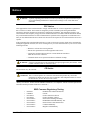
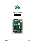
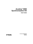
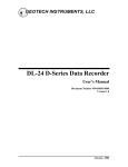
The SMART ANTENNA, see Figure 1 below, is a rugged, self-contained GPS receiver and antenna designed
for harsh tracking environments. It accepts DGPS correction signals to further enhance accuracy. The SMART
ANTENNA provides position and velocity data for a variety of applications.
Features:
•
12-channel parallel “all in view” tracking
•
L1 C/A code and carrier phase
•
RTCM-104 differential corrections input
•
-135 dBm minimum tracking sensitivity
•
1PPS output aligned to GPS time 200 ns (typical)
•
Single +5 V power input
•
Reverse polarity and SAE J1455 load dump protected
•
1 Hz position, velocity and time (PVT) output
Available Model Features1:
•
Integrated carrier phase (CP) data (Message ID# 23, Measurement Block Data only works with
these models): 1 Hz or 5 Hz CP
•
SBAS (for example WAAS and EGNOS) support
•
5 Hz PVT output
•
Precise timing
•
DGPS base station software
Figure 1: SMART ANTENNA
1.
Refer to Appendix A of the SUPERSTAR II Firmware Reference Manual for models and their
capabilities.
SMART ANTENNA User Manual Rev 6
13
Chapter 2
Installation
This section covers the installation of the SMART ANTENNA.
NovAtel’s StarView graphical user interface software running on a PC allows you to control the receiver and to
display its outputs. See Section B.2, StarView Software Installation starting on Page 45 for its installation
instructions. Details on the StarView program are provided in Reference [5] on Page 12.
2.1
Interconnections
All connections are made through a single 7-, 6- or 12-conductor cable (supplied with the development kits,
otherwise available as an option). See also the cables in Appendix A starting on Page 35 and the sections below.
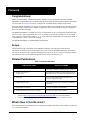
2.1.1
System Components
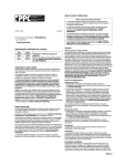
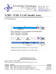
Figure 2: Standard Mount SMART ANTENNA
.
1”
OD
5/8”
ID
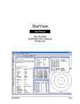
Figure 3: Mounting Adapter
Figure 4: 3 Mounting Screws and Washers
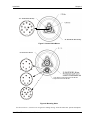
The SMART ANTENNA is normally mounted using one of the following methods:
1. Using the 1"– 14 threads, mount the antenna onto a standard antenna mast or mounting adapter.
Figure 5 on Page 15 shows the central cable mount which is also labelled as the cable exit.
2. Using three 10-32 UNF screws, mount the antenna on a flat surface with three holes on a 1.75-inch
diameter circle as shown in Figure 6 on Page 15.
14
SMART ANTENNA User Manual Rev 6
Installation
Chapter 2
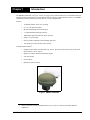
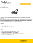
Figure 5: Central Cable Mount
7-pin (shown) or 6-pin connector for the RS-232
12-pin connector for the RS-422
Figure 6: Mounting Holes
See also Section A.3, Connector Pin Assignments starting on Page 38 for the connectors’ pin-out descriptions.
SMART ANTENNA User Manual Rev 6
15
Chapter 2
Installation
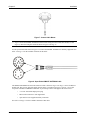
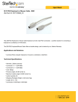
Figure 7: Central Cable Mount
Figure 7 shows the SMART ANTENNA with its cable exiting from the central cable mount, see also
Figure 5, instead of using the connector shown in Figure 6 on Page 15.
Use the open-ended cable shown in Figure 8 to connect the SMART ANTENNA to auxiliary equipment. See
Table 2 on Page 17 for the available variations of this cable.
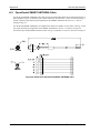
Figure 8: Open-Ended SMART ANTENNA Cable
The SMART ANTENNA RS-232 multi-connector cable is shown in Figure 9 on Page 17 and is for RS-232
models only. The receiver end of the cable connects to the 7-pin (shown in Figure 6 on Page 15) or 6-pin
receptacle of the RS-232 SMART ANTENNA. It provides up to three ends opposite the receiver end:
•
+12 V DC automobile input power plug
•
DB-9 socket connector to user-supplied PC
•
open end for a user-supplied auxiliary connection
See Table 2 on Page 17 for the available variations of this cable.
16
SMART ANTENNA User Manual Rev 6
Installation
Chapter 2
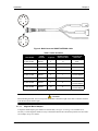
Figure 9: Multi-Connector SMART ANTENNA Cable
Table 2: Cable Variations
Part Number
Serial
Interface
Length (m)
Number of Pins
at Receiver End
Connectors at
Other End
217-601764-001
RS-422
5
12
None
217-601764-002
RS-422
30
12
None
217-601764-003
RS-422
15
12
None
217-601742-001
RS-232
5
7
None
217-601742-003
RS-232
5
7
DB-9 and a
+12 V DC adapter
217-601798-001
RS-232
5
6
None
217-601798-003
RS-232
5
6
DB-9 and a
+12 V DC adapter
217-601798-004
RS-232
15
6
DB-9 and a
+12 V DC adapter
CAUTION
When installing the cable, use a tie-wrap near the antenna to hold the weight of the cable so that the connector
is not stressed by the cable weight.
2.1.1.1
Magnetic Mount Adaptor
A magnetic mount adapter (part number 270-990146-890), see Figure 10 on Page 18 is available as an
accessory. Use this magnetic mount accessory to thread the antenna onto a mount and position on a flat surface
(for example, on top of a vehicle).
SMART ANTENNA User Manual Rev 6
17
Chapter 2
Installation
Figure 10: Magnetic Mount Adapter
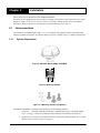
2.2
Power/Communication Port
The multi-pin connector on the SMART ANTENNA (shown in Figures 5 and 6 on Page 15), acts as both a
communication and a power port. Power can be supplied and communication can occur simultaneously using
the open-ended SMART ANTENNA cable shown in Figure 8 on Page 16 for the RS-422 or either of the cables
shown in the previous section for the RS-232 models. See also Appendix A, Technical Specifications, starting
on Page 35.
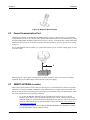
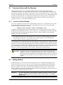
It is recommended that a back-up battery (3) is placed between the receiver (1) and its voltage supply (2) to act
as a power buffer:
1
2
+
-
3
Normally when a vehicle engine is started, power can dip to around 9.6 VDC or even cut-out to ancillary
equipment. Plug in the adapter and/or connect and turn on the power supply.
2.3
SMART ANTENNA Location
Many GPS reception problems can be reduced, to some degree, by careful antenna site selection. Of primary
importance is to place the SMART ANTENNA so that unobstructed line-of-sight reception is possible from
horizon to horizon and at all bearings and elevation angles from the antenna. This is the ideal situation, which
may not be possible under actual operating conditions.
1. Try to place the SMART ANTENNA as far as possible from reflective objects, especially
reflective objects that are above its radiation pattern horizon. Close-in reflections cause strong
multipath signals. For a detailed discussion on multipath and site selection, refer to the section on
Multipath in the GPS+ Reference Manual available on our website at http://www.novatel.com/
Downloads/docupdates.html.
2. Care should also be taken to avoid coiling the SMART ANTENNA cable around the mounting
base and pinching the cable in windows or doors.
18
SMART ANTENNA User Manual Rev 6
Installation
Chapter 2
By default, the SMART ANTENNA uses satellites above 4.5 degrees elevation. The mask angle can be set to
use a different cut-off, as low as zero degrees (all in view), using Message ID# 81, Set Mask Angle (refer to the
SUPERSTAR II Firmware Reference Manual for more message details).
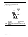
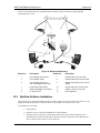
2.4
Installation Overview
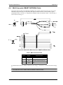
Once you have selected the appropriate equipment, set up your SMART ANTENNA and use it as in Figure 11.
1
7
2
3
6
4
5
Figure 11: Basic Setup
Reference
Description
Reference
Description
1
SMART ANTENNA
5
120 V AC power source
2
7- or 6-pin connection
6
User-supplied PC
3
DB-9 connector to PC
7
Open-ended for user-supplied
4
12 V DC adaptor
WARNING:
connector
If you are using StarView, ensure the Power Settings on your PC are not set to go into
Hibernate or Standby modes. Data will be lost if one of these modes occurs during a
logging session.
SMART ANTENNA User Manual Rev 6
19
Chapter 3
Operation
Before operating the receiver for the first time, ensure that you have followed the installation instructions in
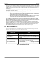
Chapter 2, Installation starting on Page 14. The following instructions are based on a configuration such as
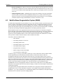
that shown in Figure 12. It is assumed that a personal computer is used during the initial operation and testing
for greater ease and versatility.
8
2
1
3
4
6
5
7
Figure 12: Typical Operational Configuration
Reference
Description
1
SMART ANTENNA
2
User-supplied PC
3
COM1
4
COM2 (DGPS IN)
5
Power
6
Radio or rover station
7
External power source(s)
8
GPS signal
Your receiver must be a BASE model to act as a base station. A list of models may be found in Appendix A
of the SUPERSTAR II Firmware Reference Manual, see Reference [6] on Page 12.
20
SMART ANTENNA User Manual Rev 6
Operation
3.1
Chapter 3
Communications with the Receiver
Communication with the receiver is straightforward, and consists of issuing commands through the
communication ports from an external serial communications device. This could be either a terminal or a PC
that is directly connected to the COM1 serial port of the receiver using a straight serial cable. If you are using
an RS-232 communications device such as a radio modem, connect it to the receiver’s COM2 (DGPS IN) port
by means of a radio serial cable. For information about input and output messages that are useful for basic
operation of the receiver, refer to the SUPERSTAR II Firmware Reference Manual. See also the StarView
examples in Section 3.2, Getting Started starting on Page 21.
3.1.1
Serial Port Default Settings
The receiver communicates with your PC or terminal through a serial port. For communication to occur, both
the receiver and the operator interface have to be configured properly. The receiver’s COM1 and COM2
(DGPS IN) default port settings are as follows:
•
9600 bps, no parity, 8 data bits, 1 stop bit, no handshaking, echo off
Changing the default baud setting requires using Message ID# 110, Configure COM1 Port Mode, which is
described in the SUPERSTAR II Firmware Reference Manual. It is recommended that you become thoroughly
familiar with the input and output messages detailed in the above reference manual to ensure maximum
utilization of the receiver’s capabilities.
The default data transfer rate is 9600 bps unless your receiver has Carrier Phase Output (CP) capability
with 19200 bps as the default. A list of models may be found in Appendix A of the SUPERSTAR II
Firmware Reference Manual, see Reference [6] on Page 12.
The data transfer rate you choose determines how fast information is transmitted. Take for example a message
whose byte count is 96. The default port settings allow 10 bits/byte. It therefore takes 960 bits per message. To
get 10 messages per second then requires 9600 bps. Please also remember that even if you set the bps to 9600
the actual data transfer rate will be less and depends on the number of satellites being tracked, filters in use, and
idle time. It is therefore suggested that you leave yourself a margin when choosing a data rate.
CAUTION:
3.2
Although the receiver can operate at data transfer rates as low as 300 bps, this is not
desirable. For example, if several data messages are active (that is, a significant amount of
information needs to be transmitted every second) but the bit rate is set too low, data will
overflow the serial port buffers, cause an error condition in the receiver status and result in
lost data.
Getting Started
Included with your receiver is NovAtel’s StarView program. StarView is a Windows-based graphical user
interface which allows you to access the receiver's many features without struggling with communications
protocol or writing special software. The information is displayed in windows accessed from the Window
menu. For example, to show details of the GPS satellites being tracked, select Satellites | Status from the
Window menu. Select Navigation | LLH Solution from the Window menu to display the position of the receiver
in LLH (latitude, longitude and height) coordinates.
WARNING:
If you are using StarView, ensure the Power Settings on your PC are not set to go into
Hibernate or Standby modes. Data will be lost if one of these modes occurs during a
logging session.
SMART ANTENNA User Manual Rev 6
21
Chapter 3
Operation
The receiver is in Navigation mode whenever sufficient satellite information and measurement data is available
to produce a GPS fix. When the receiver has a valid position, the Nav Mode field in StarView’s LLH Solution,
or XYZ Solution, window shows Nav 2-D, Nav 3-D, Diff. 2-D or Diff. 3-D. If it shows Initialized there is no
valid position yet.
The SMART ANTENNA uses a comprehensive message interface. Input messages can be sent to the receiver
using the Xmit Msg menu in StarView.
The following information is important when selecting commands:
1. You can send a message request using one shot (Normal mode) or continuous (Special mode) by
selecting Xmit Msg | General Message Request in StarView.
2. There is an option in StarView to save all messages transmitted by the receiver into a file. Select
File/Port | Save Data after you have finished selecting messages in Step #2 above.
The SUPERSTAR II Firmware Reference Manual provides the available messages and parameters that the
SMART ANTENNA uses. See also Section B.2, StarView Software Installation starting on Page 45 and refer to
the StarView User Manual for more information on the StarView program.
The receiver’s software resides in read-only memory. As such, the unit “self-boots” when turned on and
undergoes a complete self-test, see Section 3.6.2, Operational States starting on Page 24. If a persistent error
develops, please contact your local NovAtel dealer first. If the problem is still unresolved, please contact
NovAtel directly through any of the methods in the Customer Service section on Page 10.
3.3
Non Volatile Memory
The receiver stores different types of information used to accelerate the TTFF and to configure the I/O in
NVM. See Table 3 below for a partial list of the data stored in NVM.
PARAMETER
NOTES
ALMANAC
The most recent almanac
LAST POSITION
Position in NVM is updated at different rates depending on the
application. The last known position is always kept in battery backup SRAM.
DGPS CONFIGURATION
Differential GPS configuration
RS-232 CONFIGURATION
Contains the following configuration information:
1. Mode of operation
4. Time Alignment Mode State
2. Baud Rate: 300 to 19200
5. Mask Angle
3. Default Binary message list
6. Datum
Table 3: Non-Volatile Memory Data
22
SMART ANTENNA User Manual Rev 6
Operation
3.4
Chapter 3
Default Configuration
Below is the SMART ANTENNA’s default configuration with no valid NVM elements:
Protocol on port #1:
Baud Rate on port #1:
Protocol on port #2:
Baud Rate on port #2:
DGPS Correction Timeout:
Default Message List:
Binary:
NMEA:
1PPS Time Align Mode:
Binary
9600
RTCM-104
9600
120 seconds
Navigation Status User Coordinates (Message ID# 20) @ 1Hz
GGA @ 1Hz
OFF
The default data transfer rate is 9600 bps unless your receiver model has Carrier Phase Output (CP)
capability with 19200 bps as the default. A list of models may be found in Appendix A of the SUPERSTAR
II Firmware Reference Manual, see Reference [6] on Page 12.
3.5
Configurable Parameters
Several parameters of the receiver and the base station are configurable and therefore, you must define them
prior to operation.
Your receiver must be a BASE model to act as a base station. A list of models may be found in Appendix A
of the SUPERSTAR II Firmware Reference Manual, see Reference [6] on Page 12.
3.5.1
Mask Angle
The mask angle is defined as the minimum satellite elevation angle (in degrees) above which any given satellite
must be in order for it to be used in the GPS position solution. Low satellites usually do not yield accurate
measurements due to weak signal reception and possible multipath. Typical mask angle values range from 5°10°, depending on the receiver’s location. This value is programmable using command Message ID# 81, Set
Mask Angle.
3.5.2
SMART ANTENNA Position
For the base station, you must fix the position of the SMART ANTENNA. This can be done using either the XY-Z coordinates in meters within the WGS-84 reference frame, or latitude and longitude in degrees and height
in meters (LLH coordinates) by selecting Tool Setting | Set Operating Mode in the main menu of StarView.
You can only set the X-Y-Z coordinates using Message ID# 80, Set User’s Position/Operating Mode.
See also Section 2.3, SMART ANTENNA Location starting on Page 18.
3.6
Receiver States
3.6.1
Non-Operational State
The SMART ANTENNA’s non-operational state is OFF mode. In OFF mode, only the data contained in the
NVM is retained for use when power is re-applied. See Section 3.3, Non Volatile Memory starting on Page 22
for details on retained data. If your SMART ANTENNA contains a SUPERSTAR II, its supercap allows it to
maintain ephemeris, other data, and time during OFF mode for a period of 3 -7 days for a hot/quick start.
SMART ANTENNA User Manual Rev 6
23
Chapter 3
3.6.2
Operation
Operational States
The receiver has 6 operating modes:
•
Self-Test
•
Initialization
•
Acquisition
•
Navigation
•
Dead-Reckoning
•
Fault
The receiver switches between modes automatically. The receiver reports the current operating and navigation
modes on its host port.
1. Self-Test Mode
The receiver enters Self-Test mode upon request from an external source (please refer to Message
ID# 51, Initiated BIT Request in the SUPERSTAR II Firmware Reference Manual). The time
duration spent in the Self-Test mode is no more than 15 seconds. On self-test completion, the
receiver reports the BIT results on its host port through Message ID# 51. Self-Test mode exits to
either Initialization or Fault mode.
2. Initialization Mode
Upon power-up, the receiver enters Initialization mode. During this mode hardware is initialized
prior to Acquisition mode entry. The Initialization mode is also initiated upon completion of the
Self-Test mode, but always exits to the Acquisition mode.
The SMART ANTENNA retrieves data from both NVM and SRAM (warm start). Integrity
checking is done on all data retrieved from the non-operating state.
During initialization, the receiver retrieves the last received valid almanac data and last user
position from NVM, the current time from the low-power time source, and predicts which
satellites are currently visible. This list of visible satellites is then used in Acquisition mode to
program the 12 parallel correlator channels.
3. Acquisition Mode
The receiver is in Acquisition mode when insufficient satellite data is available to produce an
initial navigation solution. Acquisition mode is entered from Initialization or Dead-Reckoning
mode and exits to Navigation or Fault mode.
To acquire signals from the GPS satellites, the receiver uses:
•
Almanac data which describes the satellite orbits
•
Time, which in conjunction with almanac data is used to estimate the present
position of satellites in their orbits
•
The approximate location of the receiver so a prediction can be made as to which
satellites are visible
The receiver then collects ephemeris data by decoding the satellite down-link data message. After
each satellite in view is acquired, its measurement data set is produced. When a sufficient number
of satellites are being tracked, position, velocity and time can be computed and Navigation mode
entered.
If the receiver cannot perform an acquisition due to an absence of valid almanac data or user
position and/or time, it initiates a "Search the Sky" acquisition. The receiver attempts to acquire all
satellites in the GPS constellation. Once a satellite has been acquired, ephemeris data is decoded
24
SMART ANTENNA User Manual Rev 6
Operation
Chapter 3
from the satellite down-link message. After sufficient satellites have been acquired, the receiver
enters Navigation mode. In "Search the Sky", the TTFF is typically less than 3 minutes.
4. Navigation Mode
The receiver is in Navigation mode whenever sufficient satellite information and measurement
data is available to produce a GPS fix. Navigation mode is entered from Acquisition or DeadReckoning mode and exits to Dead-Reckoning or Fault mode.
In Navigation mode, a receiver configured as a roving unit operates in 2 sub-modes: Differential
and Stand-Alone Nav. Sub-mode transition occurs automatically depending on satellite data
availability. A receiver which is configured as a base station unit operates in Base Station Nav
mode only. The receiver reports its current navigation sub-mode on its host port.
a. Differential (Roving Unit Only)
The receiver operates in Differential mode when data from at least 4 satellites with
adequate geometry and differential corrections and/or measurements exist to compute
position, velocity and time outputs. This is the preferred navigation mode. Differential
data is supplied to the receiver through the differential input port. Differential data can be
received only on the COM2 (DGPS IN) serial data port.
b. Stand-Alone Nav (Roving Unit Only)
The receiver operates in Stand-Alone Nav mode when it has data from at least 4 satellites
with adequate geometry, but no differential corrections or measurements exist to compute
position, velocity and time outputs. This is the preferred navigation mode when
insufficient differential data is available to generate a differential GPS fix.
c. Base Station Nav (Base Station Unit Only)
The receiver operates in Base Station Nav mode once the time has been initialized and at
least 4 satellites with adequate geometry can be used for navigation purposes. Once in
this mode, only a change of configuration (rover mode requested) or a reset will cause the
unit to leave this navigation mode. In this mode, the unit will have the ability to transmit
the DGPS messages which are requested and allowed once its position is initialized. See
also Section 3.5, Configurable Parameters starting on Page 23 for position initialization
details.
Your receiver must be a BASE model to act as a base station. A list of models may be found in Appendix A
of the SUPERSTAR II Firmware Reference Manual, see Reference [6] on Page 12.
5. Dead-Reckoning Mode
The receiver enters Dead-Reckoning mode when it cannot remain in Navigation mode. The speed
and direction is assumed to be constant to allow the receiver to provide an estimated position.
6. Fault Mode
The receiver enters Fault mode during the period of time in which the receiver outputs are affected
by one or more critical system faults. This mode supersedes all others and remains active until the
next power-down/power-up cycle. Fault mode is entered from any mode except Initialization.
SMART ANTENNA User Manual Rev 6
25
Chapter 3
3.7
Operation
Built-In Status Tests
The receiver performs self-tests and generates status information to provide an indication of the operational
readiness and to facilitate maintenance actions.
The built in test monitors system performance and status to ensure the receiver is operating within its
specifications. If an exceptional condition is detected, you are informed through one or more indicators. The
receiver status system is used to configure and monitor these indicators:
•
Message ID# 49, Receiver Status Data
•
Message ID# 51, Initiated BIT Result
Please refer to the SUPERSTAR II Firmware Reference Manual for details on the Message IDs above.
See also Section 3.6.2, Operational States starting on Page 24.
3.8
DATUM Support
The receiver has the ability to provide its position in one of the 62 predefined datums. The list of the supported
datum and details on Message ID# 88, Select/Define Datum to Use are provided in the SUPERSTAR II
Firmware Reference Manual. The receiver can also support two user-defined datums. You must define them,
prior to their use, using Message ID# 88. Afterwards, the desired datum, whether it is user-defined or
predefined, can be selected using the above message.
26
SMART ANTENNA User Manual Rev 6
Chapter 4
Positioning Modes of Operation
The following single frequency modes of operation are described further in this chapter:
• Single Point or Autonomous
• Optional Satellite-Based Augmentation System (SBAS)
Refer to the GPS Overview section in the GPS+ Reference Manual, available on our website at http://
www.novatel.com/Downloads/docupdates.html, for an overview of GPS positioning.
4.1
Single-Point or Autonomous
The SMART ANTENNA is capable of absolute single-point positioning accuracies of < 5 meters CEP (GDOP
< 2 with no multipath). See also the Performance specifications on Page 36 of Appendix A.
The general level of accuracy available from single-point operation may be suitable for many types of
applications that do not require position accuracies of better than 5 m CEP. However, increasingly more and
more applications desire and require a much higher degree of accuracy and position confidence than is possible
with single-point pseudorange positioning. This is where differential GPS (DGPS) plays a dominant role in
higher accuracy real-time positioning systems. Refer to the GPS Overview section in the GPS+ Reference
Manual, available on our website at http://www.novatel.com/Downloads/docupdates.html, for an overview of
GPS positioning.
By averaging many GPS measurement epochs over several hours, it is possible to achieve a more accurate
absolute position.
The next section deals with the type of GPS system errors that can affect accuracy in single-point operation.
4.1.1
GPS System Errors
In general, GPS SPS C/A code single-point pseudorange positioning systems are capable of absolute position
accuracies of about 5 meters or less. This level of accuracy is really only an estimation, and may vary widely
depending on numerous GPS system biases, environmental conditions, as well as the GPS receiver design and
engineering quality.
There are numerous factors which influence the single-point position accuracies of any GPS C/A code
receiving system. As the following list will show, a receiver’s performance can vary widely when under the
influences of these combined system and environmental biases.
•
Ionospheric Group Delays – The earth’s ionospheric layers cause varying degrees of GPS signal
propagation delay. Ionization levels tend to be highest during daylight hours causing propagation
delay errors of up to 30 meters, whereas night time levels are much lower and may be as low as 6
meters.
•
Tropospheric Refraction Delays – The earth’s tropospheric layer causes GPS signal propagation
delays. The amount of delay is at the minimum (about three metres) for satellite signals arriving from
90 degrees above the horizon (overhead), and progressively increases as the angle above the horizon is
reduced to zero where delay errors may be as much as 50 metres at the horizon.
•
Ephemeris Errors – Some degree of error always exists between the broadcast ephemeris’ predicted
satellite position and the actual orbit position of the satellites. These errors will directly affect the
accuracy of the range measurement.
•
Satellite Clock Errors – Some degree of error also exists between the actual satellite clock time and
the clock time predicted by the broadcast data. This broadcast time error will cause some bias to the
pseudorange measurements.
SMART ANTENNA User Manual Rev 6
27
Chapter 4
Positioning Modes of Operation
•
Receiver Clock Errors – Receiver clock error is the time difference between GPS receiver time and
true GPS time. All GPS receivers have differing clock offsets from GPS time that vary from receiver
to receiver by an unknown amount depending on the oscillator type and quality (TCXO verses OCXO
and so on).
•
Multipath Signal Reception – Multipath signal reception can potentially cause large pseudorange
and carrier phase measurement biases. Multipath conditions are very much a function of specific
antenna site location versus local geography and man-made structural influences. Severe multipath
conditions could skew range measurements by as much as 100 meters or more.
4.2
Satellite-Based Augmentation System (SBAS)
A Satellite-Based Augmentation System (SBAS) is a type of geo-stationary satellite system that improves the
accuracy, integrity, and availability of the basic GPS signals. Accuracy is enhanced through the use of wide
area corrections for GPS satellite orbits and ionospheric errors. Integrity is enhanced by the SBAS network
quickly detecting satellite signal errors and sending alerts to receivers to not use the failed satellite. Availability
is improved by providing an additional ranging signal to each SBAS geostationary satellite.
SBAS includes the Wide-Area Augmentation System (WAAS), the European Geo-Stationary Navigation
System (EGNOS), and the MTSAT Satellite-Based Augmentation System (MSAS). At the time of publication,
there are two WAAS satellites over the western Atlantic Ocean and the Pacific (PRN 122 and PRN 134
respectively) and one EGNOS satellite over the eastern Atlantic Ocean (PRN 120). SBAS data is available
from any of these satellites and more satellites will be available in the future.
The primary functions of SBAS include:
•
data collection
•
determining ionospheric corrections
•
determining satellite orbits
•
determining satellite clock corrections
•
determining satellite integrity
•
independent data verification
•
SBAS message broadcast and ranging
•
system operations & maintenance
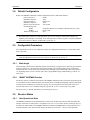
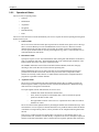
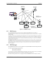
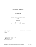
As shown in Figure 13 on Page 29, the SBAS is made up of a series of Reference Stations, Master Stations,
Ground Uplink Stations and Geostationary Satellites (GEOs). The Reference Stations, which are
geographically distributed, pick up GPS satellite data and route it to the Master Stations where wide area
corrections are generated. These corrections are sent to the Ground Uplink Stations which up-link them to the
GEOs for re-transmission on the GPS L1 frequency. These GEOs transmit signals which carry accuracy and
integrity messages, and which also provide additional ranging signals for added availability, continuity and
accuracy. These GEO signals are available over a wide area and can be received and processed by
SUPERSTAR II receivers with appropriate firmware. GPS receivers are thus able to receive SBAS data inband and use not only differential corrections, but also integrity, residual errors and ionospheric information for
each monitored satellite.
The signal broadcast through the SBAS GEOs to the SBAS users is designed to minimize modifications to
standard GPS receivers. As such, the GPS L1 frequency (1575.42 MHz) is used, together with GPS-type
modulation - e.g. a Coarse/Acquisition (C/A) pseudorandom (PRN) code. In addition, the code phase timing is
maintained close to GPS time to provide a ranging capability.
28
SMART ANTENNA User Manual Rev 6
Positioning Modes of Operation
Chapter 4
Geostationary
Satellite (GEO)
L1
GPS Satellite
Constellation
L1 & L2
L1 & C-band
Integrity data,
differential corrections,
and ranging control
GPS User
C-band
Reference Station
Reference Station
Reference Station
Ground Uplink
Station
Master Station
Integrity data,
differential corrections,
time control, and status
Figure 13: The SBAS Concept
4.2.1
SBAS Receiver
NovAtel SUPERSTAR II-based receivers may be equipped with an SBAS feature. The ability to
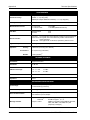
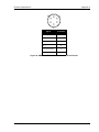
simultaneously track two SBAS satellites, and incorporate the SBAS corrections into the position, is available
on these models.
An SBAS-capable receiver will permit anyone within the area of coverage to take advantage of its benefits. To
enable SBAS, set the DGPS mode to SBAS or Automatic (refer to Message ID# 83, Set DGPS Configuration
in the SUPERSTAR II Firmware Reference Manual, see Reference [6] on Page 12). The receiver uses SBAS
satellites in your coverage area.
The SMART ANTENNA can output the SBAS data in log format (refer to Message ID# 67, WAAS Data in the
SUPERSTAR II Firmware Reference Manual), and can incorporate these corrections to generate differentialquality position solutions. SBAS data messages are analyzed based on RTCA standards for GPS/WAAS
airborne equipment.
4.2.2
SBAS Messages
The command Message ID# 95, Track SV, enables the use of particular SBAS corrections in the position filter.
Two SBAS-specific messages are also available:
Message ID# 67, SBAS Data
Message ID# 68, SBAS Status
StarView allows you to deselect GPS and SBAS system satellites. Select Tool Settings | Deselect | SVs from the
main menu. Refer also to the StarView User Manual, see Reference [5] on Page 12.
Refer also to Message ID# 30, Receiver Configuration in the SUPERSTAR II Firmware Reference Manual.
SMART ANTENNA User Manual Rev 6
29
Chapter 5
Troubleshooting
When your receiver appears not to be working properly, often there are simple ways to diagnose and resolve
the problem. In many cases, the issue can be resolved within a few minutes, avoiding the hassle and loss of
productivity that results from having to return your receiver for repair. This chapter is designed to assist you in
troubleshooting problems that occur and includes resolutions to aid your receiver in becoming operational.
If you are unsure of the symptoms or if the symptoms do not match any of those listed, use Message ID# 51,
Initiated BIT Result and refer to its description in the SUPERSTAR II Firmware Reference Manual.
If the problem is not resolved after using this troubleshooting guide, contact Customer Service, see Page 10.
This section is intended to assist you in the use of our SMART ANTENNA product.
1. If you are having problems communicating with the SMART ANTENNA:
•
•
•
•
Verify connection: look for broken pins, a misaligned connector or intermittent contact
Verify power supply input is acceptable e.g. at a good level, low ripple, and not noisy
Verify the Receive/Transmit ports are going to the correct ports on the host computer. Check
signal directions and voltage levels
Verify communication settings match the host computer for both protocol and baud rate
2. If you are experiencing problems with low SNR levels:
•
•
•
Check the SMART ANTENNA's installation, verify there is a clear view of the sky (that is,
no obstructions) and there is no reflective surface nearby that may cause multipath
interferences
Verify the cleanness (that is, low ripple, minimum noise spikes, voltage level variations) of
the power source
Check digital, RF and power ground returns. Look for noise being coupled on ground return
paths
3. If you are not receiving differential corrections:
•
•
•
Check DGPS connection on COM2 (DGPS IN) of the SMART ANTENNA
Verify DGPS source settings are active
Verify DGPS base station is actually transmitting DGPS corrections and base data is being
received by the SMART ANTENNA
Your receiver must be a BASE model to act as a base station. A list of models may be found in Appendix A
of the SUPERSTAR II Firmware Reference Manual, see Reference [6] on Page 12.
4. If you are not receiving expected messages from the SMART ANTENNA:
•
•
•
•
Verify transmit message settings (i.e. receiver's output configuration or requested message).
Verify hardware and software part numbers are the expected configuration.
Restore default settings by sending an Erase NVM command (Message ID# 99, Erase NVM)
to the SMART ANTENNA
Read the reference manual - refer to the SUPERSTAR II Firmware Reference Manual
describing message contents.
For the problems above you may be able to isolate the suspected unit in your application:
•
•
•
30
Substitute another SMART ANTENNA.
Substitute another host hardware.
Substitute alternate power source or isolate main power source from auxiliary power source
for SMART ANTENNA.
SMART ANTENNA User Manual Rev 6
Troubleshooting
Chapter 5
•
WARNING:
Make intermittent problems more repeatable (i.e. by raising operating temperature, varying
power supply source, re-orienting hardware placement). Be sure to note what makes the
problem worse / lessens the problem.
If you are using StarView, ensure the Power Settings on your PC are not set to go into
Hibernate or Standby modes. Data will be lost if one of these modes occurs during a
logging session.
Having gone through the steps in this chapter and, if possible, the substitutions above, contact Customer
Service (see Page 10).
•
•
•
•
Describe your problem, be sure to include observations, symptoms and environmental
conditions for your application.
Please supplement your problem / event descriptions with associated log files.
Give hardware part number and software part numbers (including installed configurations).
Customer support staff will give you instructions if the unit needs to be returned to the
factory.
SMART ANTENNA User Manual Rev 6
31
Chapter 6
Updating Receiver Firmware
The software update utility is specially designed to provide an easy way to update your SMART ANTENNA
software and model. The software package includes the following items:
6.1
•
An update utility, usually called update.exe (may be named otherwise)
•
An activation key
•
An application note containing the instructions as they are in this appendix
System Requirements
Before you use the update utility, make sure your computer is IBM PC-compatible with the following
minimum system requirements:
6.2
•
Intel-compatible 486DX-66 MHz CPU or higher
•
One standard serial port
•
Windows 95 operating system or higher
Utility Installation
Follow the steps below to install the Update utility:
1. Create a folder on the PC and name it “Update” for the Update utility installation. The folder name
is not critical, but avoid names that are over 8 characters long.
2. Copy the Update utility executable file (update.exe for this example) into the newly created folder.
3. Select Run from the Start menu and press the Browse button to locate update.exe in the Update
folder. Select update.exe, press the Open button and then OK.
Alternatively, you can create a shortcut to the update.exe program on your desktop.
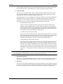
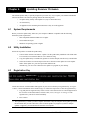
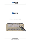
6.3
Registration Key
NovAtel Inc.
Figure 14: Update Registration Window in DOS
Contact NovAtel Inc. with the number that appears on your screen to obtain your registration key, see Figure
14 above. Contact information can be found on Page 10. Follow the steps below to enter the registration key:
1. Copy and paste the registration key from a text file or the Customer Service e-mail. Right-click on
the left corner of the DOS window, and select Edit | Paste, see Figure 15 on Page 33. The
registration key can also be entered manually.
2. Press <Enter>.
The registration key contains your host computer information. Only the computer that originally generated
the ID number that you sent to NovAtel, is able to run the update.exe program. If you have multiple
updates or upgrades, you must do them all from this one computer.
32
SMART ANTENNA User Manual Rev 6
Updating Receiver Firmware
Chapter 6
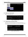
Figure 15: Paste the Registration Key into the DOS Window
6.4
Registration Key Accepted
A message confirms the Update software utility activation once the key has been entered, see Figure 16 below.
Press any key, for example <Enter>, to exit.
Figure 16: Configuration Accepted
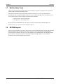
6.5
Starting Software and Options Update
Once activated, the Update utility works until the date or session counter expires. Simply follow the
instructions on the screen. The Update utility prompts you to remove or apply power to the GPS receiver. The
sessions counter decrements every time a programming session is successfully executed. An example is shown
in Figure 17 below.
NovAtel Inc. L1
Figure 17: Update Utility Activation
SMART ANTENNA User Manual Rev 6
33
Chapter 6
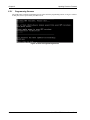
6.5.1
Updating Receiver Firmware
Programming Success
The Update utility confirms programming success at the end of the programming session, see Figure 18 below.
At this point, remove power from your GPS receiver.
Figure 18: End of Programming Session
34
SMART ANTENNA User Manual Rev 6
Appendix A
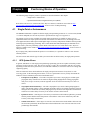
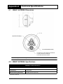
A.1
Technical Specifications
SMART ANTENNA Dimensions
7-pin (shown) or 6-pin connector for the RS-232
or 12-pin connector for the RS-422.
cable(shown)
mount also
available.
forCentral
the RS-232
or 12
male contacts
See also Figures 5 and 6 on Page 15.
A.2
SMART ANTENNA Specifications
GENERAL CHARACTERISTICSA
12-PARALLEL “ALL-IN-VIEW” TRACKING
L1 Frequency:
1,575.42 MHz
Minimum Tracking Sensitivity:
-135 dBm (antenna input level)
Continued on Page 36
SMART ANTENNA User Manual Rev 6
35
Appendix A
Technical Specifications
PERFORMANCE a
Position Accuracy:
Single Point < 5 m (16.4’) (CEP)
DGPS < 1 m (3.28’) (CEP)
SBAS (for example WAAS and EGNOS) < 1.5 m (4.92’)(CEP)
Velocity Accuracy:
0.05 m/s RMS
Measurement Precision:
L1 C/A Code
L1 Carrier Phase
75 cm RMS
1 cm RMS (differential channel)
Data Rate:
Measurements
Position
5 Hz
5 Hz
Time to First Fix:
Hot start: 15 s typical, with current almanac, position, time and ephemeris
Warm start: 45 s typical, with current almanac, position and time but no
recent ephemeris
Cold start: 166 s typical with no almanac, ephemeris, position or time
Signal Re-Acquisition:
< 1 s typical (5 s obscuration)
Dynamics:
1852 km/h (514 m/s) (1151 miles/hr) b
Velocity:
Acceleration:
Altitude:
4 G (39.2 m/s2) (128 feet/s2)
18 km (60,000’) b
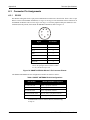
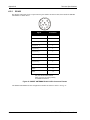
INTERNAL ANTENNA
Polarization:
Right hand circular
Axial Ratio:
3 dB max
Radiation Coverage:
θ = 90°
15° < θ < 90°
10° ≤ θ < 15°
VSWR:
2.0:1
Impedance:
50 Ω
4 dBic
-1.0 dBic
-2.5 dBic
HARDWARE SPECIFICATIONS
Input Voltage:
+9 to +36 VDC (reverse polarity protected and SAE
J1455 load dump protected)
Power Consumption:
1.4 W (typical)
Serial Communications:
COM1 input/output port and DGPS input port, available with RS-232 or RS422 interface up to 19,200 bps
Input:
Message Formats:
COM1
DGPS IN c
Output: COM1
NMEA or proprietary binary
RTCM-104 types 1, 2, 3, 9
NMEA or proprietary binary (NMEA types GGA,
GSA, GSV, RMC, VTG, ZDA, GLL plus
proprietary messages)
Continued on Page 37
36
SMART ANTENNA User Manual Rev 6
Technical Specifications
Time Mark Output:
Appendix A
1PPS output aligned to GPS time ± 200 ns typical
PHYSICAL AND ENVIRONMENTAL
Dimensions:
115 mm Diameter x 90 mm Height
(4.5" Diameter x 3.6" Height)
Weight:
575 g maximum excluding cable (1.27 lb.)
Mounting:
1-14 UNS threads x 1” deep and/or
3 x 10-32 UNF screws
Connectors:
RS-232: weathertight, 7-pin plastic or 6-pin metal
RS-422: weathertight, 12-pin standard or cable mount
See Table 6, Connector Variations on Page 41
Temperature:
Operating: -30°C to +75°C (-22°F to 167°F)
Storage: -40°C to +85°C (-40°F to 185°F)
Humidity:
SAE J1455/4.2 procedure I/II
Waterproof:
Sealed unit meets MIL-STD 810E method 512.3 (equivalent to 6-foot, 30minute submersion)
Shock:
30 g IEC 68-2-27, Test Ea (11 ms pulse)
Vibration:
Sinusoidal:
Random:
Salt Spray:
MIL-STD 810E method 509.3 (48 hours)
Chemical Resistance:
Compatible with chemicals encountered in the heavy-duty trucking industry
Sand and Dust:
MIL-STD 810E method 510.3
ESD:
IEC 1000-4-2 level 2 (± 4 KV)
EMI:
FCC Class A, European CE, 89/EEC EN55022 class B, EN50082-1
Transient Protection:
SAE J1455 4.11.2 typical vehicle transient voltage characteristic power lines
(600 Watts, 1 m/s)
Ultraviolet Light Protection:
ASTM G53-88
4 g SAE J1211, Figure 4, 1.5 hours/axis
7.5 g MIL-STD 810F method 514.5 procedure I
SMART ANTENNA DEVELOPMENT KIT
Accessories included:
SMART ANTENNA plus:
Interface cable
Bushing adapter
Magnetic mount
AC/DC adapter
CD containing StarView software and user manuals
RS-422 to RS-232 converter (RS-422 models only)
a. Typical values. Performance specifications are subject to GPS system characteristics, U.S. DOD operational degradation, ionospheric and tropospheric conditions, satellite geometry, baseline length and multipath effects. Assumes SA Off.
Specifications subject to change without notice.
b. Limited by US and Canadian export laws
c. COM2 is also called DGPS IN
SMART ANTENNA User Manual Rev 6
37
Appendix A
A.3
Technical Specifications
Connector Pin Assignments
A.3.1
RS-232
Pin numbers and signals for the 7-pin power/communication connector are shown below. There is also a 6-pin
RS-232 version of the SMART ANTENNA, see Figure 20 on Page 39. The orientation of these connectors on
the SMART ANTENNA can be seen in Figure 6 on Page 15. The most popular model (part number SA-23207W-XXX) has the pinouts (from outside the SMART ANTENNA) shown in Figure 19:
1
7
2
6
5
3
4
Signal
Pin Number
VOLTAGE_INPUT (Vin)
7
GROUND
6
RX_2
2
1PPS a
5
TX_1
3
RX_1
1
GROUND
4
a. A buffer circuit operates from Vin (9 to 36 VDC).
That is, the signal goes from Vin, down to 0 VDC
for 1 ms, and then back up to Vin.
Figure 19: SMART ANTENNA RS-232 7-Pin Connector Pinouts
The SMART ANTENNA RS-232 configurations available are shown in Table 4:
Table 4: SMART ANTENNA RS-232 Configurations
Part Numbera
SMART ANTENNA Configuration
SA-232-07W-XXX
White, 7-pin plastic connector
SA-232-06W-XXX
White, 6-pin metal connector
SA-232-06G-XXX
Green, 6-pin metal connector
DK-SA-232-07W-XXX
Dev kit, white, 7-pin plastic connector
DK-SA-232-06G-XXX
Dev kit, green, 6-pin metal connector
a. The XXX in part numbers refers to software models. Please refer to
the SUPERSTAR II Firmware Reference Manual, see Reference [6]
on Page 12.
38
SMART ANTENNA User Manual Rev 6
Technical Specifications
Appendix A
A
F
B
E
C
D
Signal
Pin Number
GROUND
A
TX_1
B
RX_2
C
RX_1
D
VOLTAGE_INPUT
E
1PPS
F
Figure 20: SMART ANTENNA RS-232 6-Pin Connector Pinouts
SMART ANTENNA User Manual Rev 6
39
Appendix A
A.3.2
Technical Specifications
RS-422
Pin numbers and signals for the 12-pin connector (part number 100-601910-002) from outside the SMART
ANTENNA are shown below.
9
8
12
7
6
Signal
1
2
10
11
5
3
4
Pin Number
POWER
1
GROUND 9
9
RX_DATA_1-
2
RX_DATA_1+
3
TX_DATA_1-
4
TX_DATA_1+
5
RX_DATA_2-
6
RX_DATA_2+
7
TX_DATA_2- a
8
TX_DATA_2+ a
10
1PPS+
11
1PPS-
12
a. Alternate signal assignments on these
pins (such as TX2 and an external
battery connection for memory backup)
are available as variations.
Figure 21: SMART ANTENNA RS-422 12-Pin Connector Pinouts
The SMART ANTENNA RS-422 configurations available are shown in Table 5 on Page 41:
40
SMART ANTENNA User Manual Rev 6
Technical Specifications
Appendix A
Table 5: SMART ANTENNA RS-422 Configurations
Part Number a
SMART ANTENNA Configuration b
SA-422-12W-XXX
White, 12-pin plastic connector, standard cable mount
SA-422-CMW-XXX
White, 12-pin plastic connector, central cable mount
DK-SA-422-12W-XXX
Dev kit, 12-pin plastic connector, standard cable mount
a. The XXX in part numbers refers to software models. Please refer to the SUPERSTAR II Firmware
Reference Manual, see Reference [6] on Page 12.
b. For alternate signal assignments on these pins (such as TX2 and an external battery connection for
memory backup), please contact NovAtel Inc. as shown in Customer Service on Page 10.
A.4
Connections
The following connector variations are available:
Table 6: Connector Variations
Connector
Manufacturer
Connector on the SMART
ANTENNA
RS-232
Switchcraft
7-pin plug: EN3P7MP
7-contact socket: EN3C7FC
RS-232
ConXall
7-pin plug: 7281-7PG-300
7-contact socket: 6282-7SG-3XX
RS-232
FCI
6-pin plug: 851-07A10-6P50
6-contact socket: 851-06TI0-6S50
RS-422 (standard mount)
Deutsch
12-pin plug: 680023-2212P1
12-contact socket: MMP26C-2212S1
RS-422 (central mount)
Deutsch
12-pin plug: MMP21-2212P1
12-contact socket: MMP26C-2212S1
SMART ANTENNA
SMART ANTENNA User Manual Rev 6
Cable Mating Connector
41
Appendix A
A.5
Technical Specifications
Open-Ended SMART ANTENNA Cable
For the RS-232 SMART ANTENNA, this cable provides an unterminated cable end for connecting directly to
other equipment. Figure 22 shows the 6-pin version of the cable. See also Table 2, Cable Variations on Page 17
and the 7-pin and 6-pin connector pin assignments on the SMART ANTENNA in Section A.3.1, RS-232
starting on Page 38.
For the RS-422 SMART ANTENNA, two lengths of this cable are available. See also Table 2 on Page 17 and
the 12-pin connector pin assignments on the SMART ANTENNA in Section A.3.2, RS-422 on Page 40.
See also the Open-Ended SMART ANTENNA Cable on Page 16 and Table 6, Connector Variations on Page 41.
Figure 22: RS-232 6-Pin Open-Ended SMART ANTENNA Cable
42
SMART ANTENNA User Manual Rev 6
Technical Specifications
A.6
Appendix A
Multi-Connector SMART ANTENNA Cable
This multi-connector cable for the SMART ANTENNA uses separate connectors for DC power (a 12 V DC
automobile input power plug), for the primary data signals (a DB-9 connector), and for auxiliary signals
(unterminated wires), see Figure 23. The pinout for the DB-9 connector is shown in Table 7. See also Table 2,
Cable Variations on Page 17.
Figure 23: RS-232 6-Pin Multi-Connector SMART ANTENNA Cable
Table 7: DB-9 Connector Pinout
Pin #
Signal
Signal Direction
2
TX1
To host computer receive port.
3
RX1
From host computer transmit port
5
GND
N/A
See also the Multi-Connector SMART ANTENNA Cable on Page 17 and Table 6, Connector Variations on Page
41.
This multi-cable is not available for RS-422 SMART ANTENNA models.
SMART ANTENNA User Manual Rev 6
43
Appendix B
B.1
SMART ANTENNA Development Kit
Development Kit
The SMART ANTENNA Development Kit allows you to easily evaluate the SMART ANTENNA. The
Development Kit implements the receiver’s operation and I/O functions using a PC, a serial/power cable with a
120 V AC to 12 V DC power adapter. The SUPERSTAR II is contained in the SMART ANTENNA unit, with
an external serial/power connector.
StarView is a Windows application running on a PC that allows communication with the receiver. Commands
and data requests can be sent through this application and received data is decoded and displayed in specific
windows. A data logging facility is also provided within this tool. Details on the use of StarView is provided in
the StarView User Manual (see Reference [5] on Page 12).
This section explains how to configure the Development Kit receiver, and how to interconnect the equipment.
See Page 37 for a list of SMART ANTENNA Development Kit contents and Table 4 and Table 5 starting on
Page 38 for variations in SMART ANTENNA models.
B.1.1
Setup and Operation
The default data transfer rate is 9600 bps unless your receiver model has Carrier Phase Output (CP)
capability with 19200 bps as the default.
Your receiver must be a BASE model to act as a base station.
A list of models may be found in Appendix A of the SUPERSTAR II Firmware Reference Manual, see
Reference [6] on Page 12.
B.1.1.1
Normal Setup
See Figure 11 on Page 19 when following these instructions:
1. Connect the SMART ANTENNA to a PC using the multi-purpose cable if it is provided.
2. Connect the power supply to the SMART ANTENNA using the power connector on the multipurpose cable.
3. Launch the StarView software application, see StarView Software Installation on Page 45. Refer
also to the StarView User Manual, see Reference [5] on Page 12.
B.1.1.2
DGPS Setup with the SMART ANTENNA
Set up the equipment as in Figure 24 on Page 45, for differential messages. Differential operation requires that
stations operate in pairs. Each pair consists of a base station and a rover station. For each receiver, the base and
the rover, follow the set-up steps in Section B.1.1.1 on Page 44. Then also connect a RS-232 communications
device to each SMART ANTENNA with a user-supplied connector on the multi-purpose cable’s open end. For
example this might connect to a radio modem, for sending or receiving differential GPS messages.
A differential network can also be established when there is more than one rover station linked to a single base
station.
The base SMART ANTENNA must be initialized to fix its position (latitude, longitude and height of its phase
center).
The rover station must be tracking the same satellites as the base station in order for corrections to take effect.
Only common satellite pseudoranges will use the differential corrections. When the rover is able to compute its
positions based on pseudorange corrections from the base station, its position accuracies will approach that of
44
SMART ANTENNA User Manual Rev 6
SMART ANTENNA Development Kit
Appendix B
the base station. Remember, the computed position solutions are that of the GPS receiving SMART
ANTENNA phase center.
1
1
2
6
10
3
2
5
4
8
9
7
11
12
11
12
Figure 24: Differential GPS Setup
Reference
B.2
Description
Reference
Description
1
User-supplied radio data link
7
FlexPak COM1 port to PC cable
2
User-supplied modem
8
FlexPak COM2 port to modem cable
3
User-supplied connector on
open end of SMART multi-cable
9
SMART multi-cable to power, PC and
modem
4
FlexPak-SSII (base station)
10
FlexPak ANT port to antenna cable
5
SMART ANTENNA (rover station)
11
Adaptor to power source cable
6
L1 GPS antenna
12
User-supplied PC
StarView Software Installation
Once the receiver is connected to the PC and power supply, install the StarView software. The StarView CD is
supplied with the development kit, otherwise StarView is available on our website (see below).
To install StarView from CD:
1. Start up the PC.
2. Insert the StarView CD in the CD-ROM drive of the computer.
3. Install the StarView software by following the steps on the screen. If the Setup utility is not
automatically accessible when the CD is inserted, select Run from the Start menu and press the
Browse button to locate Setup.exe on the CD drive.
SMART ANTENNA User Manual Rev 6
45
Appendix B
SMART ANTENNA Development Kit
4. Click on the OK button to install the StarView software and follow the steps on the screen.
From our website:
1. Start up the PC and launch your internet service program.
2. Go to our website at http://www.novatel.com/Downloads/fwswupdates.html and scroll down to the
Superstar II Family Firmware/Software section.
3. Download the StarView setup program and save it in a temporary directory (for example, C:\temp).
4. Use the setup program to install the StarView software by following the steps on the screen.
After installation, StarView also appears in the Windows Start menu at Start | Program Files | NovAtel L1
Software.
46
SMART ANTENNA User Manual Rev 6
Index
A
accuracy, 27, 36, 44
acquisition, 24
alignment, 23
almanac, 22, 24
antenna site, 28
B
base, 23, 25, 44
baud rate, 21, 23
broadcast ephemeris, 27
buffer, 21
C
cables
connector, 14, 16, 42
interface, 44
serial, 21
warranty, 9
cautions, 17, 21
CD, 45
chemical resistance, 37
communication, 18, 21, 30, 36, 44
components, 14
configuration, 20–21, 23
connector, 14, 16, 37, 42, 44–45
Customer Service, 10
D
datum, 26
dead-reckoning mode, 25
defaults, 21, 23
development kit, 37, 44
DGPS, 22–23
differential
corrections, 30, 44
mode, 25
setup, 44
dilution of precision (DOP), 27
dimensions, 35, 37
dust, 37
dynamics, 36
E
Electrostatic Discharge (ESD), 37
ephemeris, 24, 27
SMART ANTENNA User Manual Rev 6
errors, 26–27
F
fault mode, 25
features, 21
firmware update, 10
fix, 44
frequency, 35
G
GEO, SBAS, 28
GPS time, 28
H
handshaking, 21
humidity, 37
I
I/O, 22
ID# 20, Navigation Data (User), 23
idle time, 21
initialization, 24
input, 30
installation, 14
ionosphere, 27
K
kit, development, 37, 44
M
mask angle, 23
memory, 23
messages
default, 23
input, 36
mode
differential, 25
fault, 25
operational, 24
stand-alone nav, 25
modem, 44
mounting, 14, 18, 37
N
navigation mode, 25
non-volatile memory (NVM), 22–23
47
Index
O
OCXO, see oscillators
operation, 20, 24
oscillators, 28
output, 30
P
parameter, receiver, 23
parity, 21
performance, 36
pin assignments, 38
port, 18, 21
position, 22, 44
power, 18
propagation, 27
protection, 37
protocol, 23
pseudorange positioning, 27
mark, 37
to first fix (TTFF), 22, 36
tracking sensitivity, 35
transient protection, 37
troposphere, 27
troubleshooting, 30
U
ultraviolet light protection, 37
update firmware, 10
W
warnings, 11
warranty, 9
weight, 37
R
radio modem, 44
re-acquisition, 36
rover, 25, 44
S
salt spray, 37
sand, 37
satellite
acquisition, 24
records, number of, 21
SBAS, 28–29
scope, 12
self-test, 22, 24, 26
sensitivity, tracking, 35
serial communication, 21, 36
setup, 44–45
SNR, 30
software, StarView, 45
stand-alone nav mode, 25
StarView software, 14, 44–45
station, base, 23, 25
status, 26
T
TCXO, see oscillators
temperature, 37
time
data, 24
48
SMART ANTENNA User Manual Rev 6
OM-20000078
Rev 6
2005/06/09