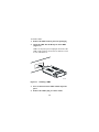
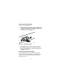
1
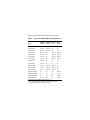
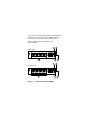
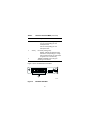
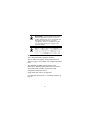
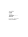
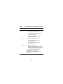
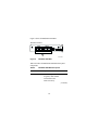
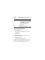
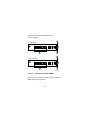
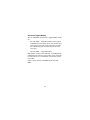
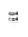
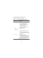
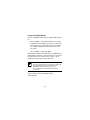
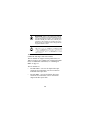
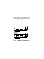
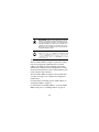
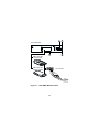
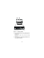
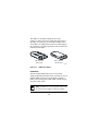
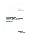
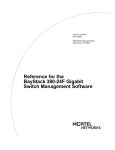
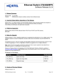
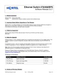
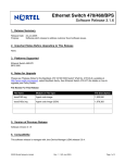
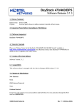
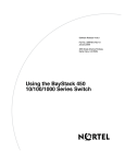
Installing Media
Dependent Adapters
(MDAs)
Part No. 302403-F Rev 00
March 2001
TM
Copyright © 2001 Nortel Networks.
All rights reserved. March 2001.
Trademarks
Nortel Networks, the Nortel Networks logo, the Globemark, Unified Networks,
BayStack, and Business Policy Switch 2000 are trademarks of Nortel Networks.
Statement of Conditions
In the interest of improving internal design, operational function, and/or reliability,
Nortel Networks Inc. reserves the right to make changes to the products described in
this document without notice.
Nortel Networks Inc. does not assume any liability that may occur due to the use or
application of the product(s) or circuit layout(s) described herein.
Federal Communications Commission (FCC) Compliance Notice:
Radio Frequency Notice
Note: This equipment has been tested and found to comply with the limits for a
Class A digital device, pursuant to Part 15 of the FCC rules. These limits are
designed to provide reasonable protection against harmful interference when the
equipment is operated in a commercial environment. This equipment generates,
uses, and can radiate radio frequency energy. If it is not installed and used in
accordance with the instruction manual, it may cause harmful interference to radio
communications. Operation of this equipment in a residential area is likely to cause
harmful interference, in which case users will be required to take whatever
measures may be necessary to correct the interference at their own expense.
EN 55 022 Declaration of Conformance
This is to certify that the Nortel Networks MDAs are shielded against the generation
of radio interference in accordance with the application of Council Directive 89/
336/EEC, Article 4a. Conformity is declared by the application of EN 55 022 Class
A (CISPR 22).
Warning: This device is a Class A product. In a domestic environment, this product
may cause radio interference, in which case, the user may be required to take
appropriate measures.
These products conform to the provisions of Council Directive 89/336/EEC and 72/
23/EEC. The Declaration of Conformity is available on the Nortel Networks World
Wide Web site at www.nortelnetworks.com.
Introduction
This guide shows how to install media dependent adapters
(MDAs) into supported Nortel Networks* products.
Table 1 lists the available MDA models.
Table 1.
MDA Models
Interface Type
Model
Refer to:
10BASE-T/100BASE-TX
(UTP)
•
•
•
400-4TX MDA
8100-4TX MDA
BPS2000-4TX MDA
page 3
100BASE-FX (Fiber)
•
•
•
•
•
•
400-2FX MDA
8100-2FX MDA
BPS2000-2FX MDA
400-4FX MDA
8100-4FX MDA
BPS2000-4FX MDA
page 8
1000BASE-SX
(Shortwave gigabit fiber)
•
•
450-1SR MDA
450-1SX MDA
page 21
1000BASE-LX
(Longwave gigabit fiber)
•
•
450-1LR MDA
450-1LX MDA
page 24
ATM
•
•
450-2M3 MDA
450-2S3 MDA
page 27
GBIC
•
450-1GBIC MDA
page 31
Nortel Networks is constantly adding new models and
features to existing product lines; for a full range of MDAs
that are available from Nortel Networks, see your Nortel
Networks sales representative.
1
Table 2 lists the supported Nortel Networks products.
Table 2.
1
2
Supported Products/Minimum SW Versions
Model
BayStack
3501/450
Business
BayStack Passport Policy
410-24T
8132
Switch2
400-4TX MDA
Yes/V1.0
Yes/V1.0
No
No
400-2FX MDA
Yes/V1.0
Yes/V1.0
No
No
400-4FX MDA
Yes/V1.3
Yes/V1.3
No
No
450-1SR MDA
Yes/V1.0
No
Yes/V1.0
Yes/V1.0
450-1SX MDA
Yes/V1.0
No
Yes/V1.0
Yes/V1.0
450-1LR MDA
Yes/V1.0
No
Yes/V1.0
Yes/V1.0
450-1LX MDA
Yes/V1.0
No
Yes/V1.0
Yes/V1.0
450-2M3 MDA
Yes/V4.0
No
No
No
450-2S3 MDA
Yes/V4.0
No
No
No
8100-4TX MDA
Yes/V1.0
Yes/V1.0
Yes/V1.0
No
8100-2FX MDA
Yes/V1.0
Yes/V1.0
Yes/V1.0
No
8100-4FX MDA
Yes/V1.3
Yes/V1.3
Yes/V1.0
No
BPS2000-4TX MDA
No
No
No
Yes/V1.0
BPS2000-2FX MDA
No
No
No
Yes/V1.0
BPS2000-4FX MDA
No
No
No
Yes/V1.0
450-1GBIC MDA
Yes/V4.0
No
No
Yes/V1.1
BayStack 350 10/100/1000 Series switches only.
In this document, the term “Business Policy Switch” refers to the
Nortel Networks Business Policy Switch 2000*.
2
Note: The MDAs are not hot-swappable. Power down
the BayStack switch or disconnect the Passport 8132
module from the switch backplane before installing or
removing an MDA.
10BASE-T/100BASE-TX MDAs
This section describes three 10BASE-T/100BASE-TX
MDA models. The three models can support various
product lines (see Table 2 on page 2 for a complete list of
supported product lines). For installation instructions, see
“Installing an MDA” on page 35.
The three 10BASE-T/100BASE-TX MDA models are:
•
400-4TX MDA
Not supported on the Business Policy Switch or
Passport 8132.
•
8100-4TX MDA
Supports BayStack 350/450/410 and Passport 8132.
•
BPS2000-4TX MDA
Supports the Business Policy Switch.
The three models each use four 10BASE-T/100BASE-TX
RJ-45 (8-pin modular) connectors, that are configured as
media dependent interface-crossover (MDI-X) connectors.
These ports connect over straight cables to the network
interface controller (NIC) card in a node or server, similar
to a conventional Ethernet repeater hub.
3
If you connect to another Ethernet hub or Ethernet switch,
you need a crossover cable unless an MDI connection
exists on the associated port of the attached device.
Figure 1 shows the 400-4TX MDA and the
8100-4TX MDA.
1
2
400-4TX MDA
100
10
F Dx
Activity
400-4TX MDA
5
4
1
3
2
8100-4TX MDA
100
10
F Dx
Activity
8100-4TX MDA
5
4
3
BS45042B
Figure 1.
400-4TX and 8100-4TX MDAs
4
The 10BASE-T/100BASE-TX MDA ports can operate at
either 10 Mb/s or 100 Mb/s. The port speed is determined
through autonegotiation with its connecting device.
Table 3 describes the 400-4TX MDA and the
8100-4TX MDA front-panel components.
Table 3.
400-4TX / 8100-4TX MDA
Item
Label
Description
1
100
100BASE-TX port status LEDs (green):
On: The corresponding port is set to
operate at 100 Mb/s.
Off: The link connection is bad or there is
no connection to this port.
Blinking: The corresponding port is
management disabled.
2
10
10BASE-T port status LEDs (green):
On: The corresponding port is set to
operate at 10 Mb/s.
Off: The link connection is bad or there is
no connection to this port.
Blinking: The corresponding port is
management disabled.
(continued)
5
Table 3.
400-4TX / 8100-4TX MDA (continued)
Item
Label
Description
3
F Dx
Full-duplex port status LEDs (green):
On: The corresponding port is in
full-duplex mode.
Off: The corresponding port is in
half-duplex mode.
4
Activity
Port activity LEDs (green):
Blinking: Indicates the network activity
level for the corresponding port. A high
level of network activity can cause LEDs
to appear to be on continuously.
5
10BASE-T/100BASE-TX RJ-45 (8-pin
modular) port connectors.
Figure 2 shows the BPS2000-4TX MDA.
1
BPS2000-4TX MDA
2
3
9792EA
Figure 2.
BPS2000-4TX MDA
6
Table 4 describes the BPS2000-4TX MDA front-panel
components.
Table 4.
BPS2000-4TX MDA
Item
Label
Description
1
10/100
10BASE-T/100BASE-TX port status LEDs:
On (green): The corresponding port is set
to operate at 100 Mb/s.
On (yellow): The corresponding port is
set to operate at 10 Mb/s.
Off: The link connection is bad or there is
no connection to this port.
2
Activity
Port activity LEDs (green):
Blinking (green): Indicates the network
activity level for the corresponding port. A
high level of network activity can cause
LEDs to appear to be on continuously.
Off: No traffic to this port.
3
10BASE-T/100BASE-TX RJ-45
(8-pin modular) port connectors.
7
100BASE-FX MDAs
Warning: Fiber optic equipment can emit laser
or infrared light that can injure your eyes. Never
look into an optical fiber or connector port.
Always assume that fiber optic cables are
connected to a light source.
Vorsicht: Glasfaserkomponenten können
Laserlicht bzw. Infrarotlicht abstrahlen, wodurch
Ihre Augen geschädigt werden können. Schauen
Sie niemals in einen Glasfaser-LWL oder ein
Anschlußteil. Gehen Sie stets davon aus, daß das
Glasfaserkabel an eine Lichtquelle angeschlossen
ist.
Avertissement: L’équipement à fibre optique
peut émettre des rayons laser ou infrarouges qui
risquent d’entraîner des lésions oculaires. Ne
jamais regarder dans le port d’un connecteur ou
d’un câble à fibre optique. Toujours supposer que
les câbles à fibre optique sont raccordés à une
source lumineuse.
Advertencia: Los equipos de fibra óptica
pueden emitir radiaciones de láser o infrarrojas
que pueden dañar los ojos. No mire nunca en el
interior de una fibra óptica ni de un puerto de
conexión. Suponga siempre que los cables de fibra
óptica están conectados a una fuente luminosa.
8
Avvertenza: Le apparecchiature a fibre ottiche
emettono raggi laser o infrarossi che possono
risultare dannosi per gli occhi. Non guardare mai
direttamente le fibre ottiche o le porte di
collegamento. Tenere in considerazione il fatto
che i cavi a fibre ottiche sono collegati a una
sorgente luminosa.
This section describes the six 100BASE-FX MDA models
(three dual-port and three quad-port models).
The six models can support various product lines (see
Table 2 on page 2 for a complete list of supported product
lines).
The 100BASE-FX MDA models conform to the
IEEE 802.3u 100BASE-FX standard and can be used to
attach fiber-based 100 Mb/s connections to other
compatible Fast Ethernet devices.
Single-mode fiber cable is not supported.
For installation instructions, see “Installing an MDA” on
page 35.
9
Dual-Port 100BASE-FX Models
The three dual-port models are:
•
400-2FX MDA
Not supported on the Business Policy Switch and
Passport 8132.
•
8100-2FX MDA
Supports BayStack 350/450, BayStack 410, and
Passport 8132 Modules.
•
BPS2000-2FX MDA
Supports the Business Policy Switch.
The three dual-port 100BASE-FX MDA models each use
two longwave 1300 nm SC connectors to attach devices
over 62.5/125 micron multimode fiber optic cable.
Figure 3 shows the 400-2FX MDA and the
8100-2FX MDAs.
10
1
2
400-2FX MDA
100BASE-FX
100BASE-FX
Link
F Dx
Activity
TX
RX
TX
RX
400-2FX MDA
3
4
1
2
8100-2FX MDA
100BASE-FX
100BASE-FX
Link
F Dx
Activity
TX
RX
TX
RX
8100-2FX MDA
3
4
BS45071A
Figure 3.
400-2FX and 8100-2FX MDAs
Table 5 describes the 400-2FX MDA and the
8100-2FX MDA front-panel components.
11
Table 5.
400-2FX MDA / 8100-2FX MDA Description
Item
Label
Description
1
Link
Communications link LEDs (green):
On: Valid communications link.
Off: Invalid communications link or no
connection to this port.
Blinking: The corresponding port is
management disabled.
2
F Dx
Full-duplex port status LEDs (green):
On: The corresponding port is in
full-duplex mode.
Off: The corresponding port is in
half-duplex mode.
3
Activity
Port activity LEDs (green):
Blinking: Indicates the network activity
level for the corresponding port. A high
level of network activity can cause LEDs
to appear to be on continuously.
4
100BASE-FX port connectors:
Models 400-2FX and 8100-2FX use SC
connectors.
12
Figure 4 shows the BPS2000-2FX MDA.
BPS2000-2FX MDA
1
BPS2000-2FX MDA
2
3
BPS20001A
Figure 4.
BPS2000-2FX MDA
Table 6 describes the BPS2000-2FX MDA front-panel
components.
Table 6.
BPS2000-2FX MDA Description
Item
Label
Description
1
Link
Link status LEDs (green):
On (green): Valid 100 Mb/s
communications link.
Off: No link activity.
(continued)
13
Table 6.
BPS2000-2FX MDA Description (continued)
Item
Label
Description
2
Activity
Port activity LEDs (green):
On: Indicates the network activity level for
the corresponding port. A high level of
network activity can cause LEDs to
appear to be on continuously.
Off: No activity.
3
100BASE-FX port connectors:
The BPS2000-2FX MDA uses SC connectors.
Quad-Port 100BASE-FX Models
The three quad-port models are:
•
400-4FX MDA
Not supported on the Business Policy Switch or
Passport 8132.
•
8100-4FX MDA
Supports BayStack 350/450, BayStack 410, and
Passport 8132 Modules.
•
BPS2000-4FX MDA
Supports the Business Policy Switch.
The three quad-port 100BASE-FX models each use four
longwave 1300 nm MT-RJ connectors to attach devices
over 62.5/125 micron multimode fiber optic cable.
14
Figure 5 shows the 400-4FX MDA and the
8100-4FX MDA.
1
400-4FX MDA
Link
2
F Dx
Activity
400-4FX MDA
3
4
1
8100-4FX MDA
Link
2
F Dx
Activity
8100-4FX MDA
3
4
BS45072A
Figure 5.
400-4FX and 8100-4FX MDAs
Table 7 describes the 400-4FX MDA and the 8100-4FX
MDA front-panel components.
15
Table 7.
400-4FX MDA / 8100-4FX MDA Description
Item
Label
Description
1
Link
Communications link LEDs (green):
On: Valid communications link.
Off: Invalid communications link or no
connection to this port.
Blinking: The corresponding port is
management disabled.
2
F Dx
Full-duplex port status LEDs (green):
On: The corresponding port is in
full-duplex mode.
Off: The corresponding port is in
half-duplex mode.
3
Activity
Port activity LEDs (green):
Blinking: Indicates the network activity
level for the corresponding port. A high
level of network activity can cause LEDs
to appear to be on continuously.
4
100BASE-FX port connectors:
Models 400-4FX and 8100-4FX use MT-RJ
connectors.
16
Figure 6 shows the BPS2000-4FX MDA.
BPS2000-4FX MDA
1
BPS2000-4FX MDA
3
Figure 6.
2
BPS20002A
BPS2000-4FX MDA
Table 8 describes the BPS2000-4FX MDA front-panel
components.
Table 8.
BPS2000-4FX MDA Description
Item
Label
Description
1
Link
Link status LEDs (green):
On (green): Valid 100 Mb/s
communications link.
Off: No link activity.
(continued)
17
Table 8.
BPS2000-4FX MDA Description (continued)
Item
Label
Description
2
Activity
Port activity LEDs (green):
On: Indicates the network activity level for
the corresponding port. A high level of
network activity can cause LEDs to
appear to be on continuously.
Off: No activity.
3
100BASE-FX port connectors:
The BPS2000-4FX MDA uses MT-RJ
connectors.
18
1000BASE-X MDAs
Warning: This is a Class 1 Laser/LED product. It
contains a laser light source that can injure your
eyes. Never look into an optical fiber or connector
port. Always assume that the fiber optic cable or
connector is connected to a laser light source.
Vorsicht: Dieses Laser/LED-Produkt der
Klasse 1 enthält eine Laserlichtquelle, die zu
Augenverletzungen führen kann. Sehen Sie nie in
einen Lichtwellenleiter oder
Glasfaserstecker-Port. Gehen Sie immer davon
aus, daß das Glasfaserkabel oder der
Glasfaserstecker an eine Laserlichtquelle
angeschlossen ist.
Avertissement: Ceci est un appareil Laser/DEL
de Classe 1. Cet appareil contient une source
lumineuse à rayons laser dangereuse pour les
yeux. Ne regardez jamais directement une fibre
optique ou un port de connexion. Agissez
toujours comme si le câble de fibres optiques ou le
connecteur était relié à une source lumineuse à
rayons laser.
Advertencia: Éste es un producto láser/LED de
Clase 1. Contiene una fuente de luz láser que
puede causar lesiones en los ojos. Nunca mire
dentro de un cable o de un puerto de conexión de
fibra óptica. Asuma siempre que el cable o el
connector de fibra óptica está conectado a una
fuerte de luz láser.
19
Avvertenza: Questo è un produtto laser/LED di
Classe 1 e contiene una sorgente luminosa a laser
che può danneggiare gli occhi. Non guardare mai
all’interno di una port a fibra ottica o di una porta
connettore. Dare sempre per scontato che il cavo
di fibra ottica o il connettore siano collegati ad una
sorgente luminosa a laser.
This section describes the four 1000BASE-X MDA
models:
Two shortwave gigabit models:
•
450-1SR MDA
•
450-1SX MDA
Two longwave gigabit models:
•
450-1LR MDA
•
450-1LX MDA
The four models can support various product lines (see
Table 2 on page 2 for a complete list of supported product
lines). For installation instructions, see “Installing an
MDA” on page 35.
20
Shortwave Gigabit Models
The two 1000BASE-SX (shortwave gigabit) MDA models
are:
•
450-1SR MDA -- single MAC MDA with a separate
redundant Phy (backup Phy port). Only one Phy port
can be active at any time. If the active Phy port fails,
the redundant Phy port automatically becomes the
active port.
•
450-1SX MDA -- single PHY MDA.
Both models conform to the IEEE 802.3z 1000BASE-SX
standard and use shortwave 850 nm fiber optic connectors
to connect devices over multimode (550 m/1805 ft) fiber
optic cable.
Figure 7 shows the 450-1SR MDA and the 450-1SX
MDA.
21
1
450-1SR MDA
(1-port redundant)
1000BASE-SX
2
1000BASE-SX
Link
Phy Select
Activity
TX
RX
TX
RX
450-1SR MDA
3
4
1
450-1SX MDA
(single port)
2
1000BASE-SX
Link
Phy
Activity
TX
RX
450-1SX MDA
3
4
BS45044A
Figure 7.
450-1SR and 450-1SX MDA Front Panels
22
Table 9 describes the 450-1SR MDA and the
450-1SX MDA front-panel components.
Table 9.
450-1SR / 450-1SX MDA Description
Item
Label
Description
1
Link
Communication link LEDs (green):
On: Valid communications link.
Off: The communications link
connection is bad or there is no
connection to this port.
Blinking: The corresponding port is
management disabled.
2
Phy
(or)
Phy Select
Phy status LEDs (green):
On: The corresponding Phy port is
active.
Off: The corresponding Phy port is in
backup mode or there is no connection
to this port.
3
Activity
Port activity LEDs (green):
Blinking: Indicates network activity
level for the corresponding port. A high
level of network activity can cause
LEDs to appear to be on continuously.
4
1000BASE-X SC port connectors.
23
Longwave Gigabit Models
The two 1000BASE-LX (longwave gigabit) MDA models
are:
•
450-1LR MDA -- single MAC MDA with a separate
redundant Phy (backup Phy port). Only one Phy port
can be active at any time. If the active Phy port fails,
the redundant Phy port automatically becomes the
active port.
•
450-1LX MDA -- single Phy MDA.
Both models conform to the IEEE 802.3z 1000BASE-LX
standard and use longwave 1300 nm fiber optic connectors
to connect devices over single mode (5 km/3.1 mi) or
multimode (550 m/1805 ft) fiber optic cable.
Note: The optical performance of this transceiver
cannot be guaranteed when connected to a multimode
fiber plant without the use of the special offset
SMF/MMF mode conditioning patch cord
(see “1000BASE-LX Multimode Applications”
on page 42).
Figure 8 shows the 450-1LR MDA and the
450-1LX MDA.
24
1
450-1LR MDA
(1-port redundant)
1000BASE-LX
2
1000BASE-LX
Link
Phy Select
Activity
TX
RX
TX
RX
450-1LR MDA
3
4
1
450-1LX MDA
(single port)
2
1000BASE-LX
Link
Phy
Activity
TX
RX
450-1LX MDA
3
4
BS45045A
Figure 8.
450-1LR and 450-1LX MDA Front Panels
Table 10 describes the 450-1LR MDA and the
450-1LX MDA front-panel components.
25
Table 10.
450-1LR and 450-1LX MDA Description
Item
Label
Description
1
Link
Communication link LEDs (green):
On: Valid communications link.
Off: The communications link
connection is bad or there is no
connection to this port.
Blinking: The corresponding port is
management disabled.
2
PHY
(or)
Phy Select
Phy status LEDs (green):
On: The corresponding Phy port is
active.
Off: The corresponding Phy port is in
backup mode or there is no connection
to this port.
3
Activity
Port activity LEDs (green):
Blinking: Indicates network activity
level for the corresponding port. A high
level of network activity can cause
LEDs to appear to be on continuously.
4
1000BASE-X SC port connectors (see
“1000BASE-LX Multimode Applications” on
page 42 for special requirements).
26
ATM MDAs
Warning: This is a Class 1 Laser/LED product. It
contains a laser light source that can injure your
eyes. Never look into an optical fiber or connector
port. Always assume that the fiber optic cable or
connector is connected to a laser light source.
Vorsicht: Dieses Laser/LED-Produkt der
Klasse 1 enthält eine Laserlichtquelle, die zu
Augenverletzungen führen kann. Sehen Sie nie in
einen Lichtwellenleiter oder
Glasfaserstecker-Port. Gehen Sie immer davon
aus, daß das Glasfaserkabel oder der
Glasfaserstecker an eine Laserlichtquelle
angeschlossen ist.
Avertissement: Ceci est un appareil Laser/DEL
de Classe 1. Cet appareil contient une source
lumineuse à rayons laser dangereuse pour les
yeux. Ne regardez jamais directement une fibre
optique ou un port de connexion. Agissez
toujours comme si le câble de fibres optiques ou le
connecteur était relié à une source lumineuse à
rayons laser.
Advertencia: Éste es un producto láser/LED de
Clase 1. Contiene una fuente de luz láser que
puede causar lesiones en los ojos. Nunca mire
dentro de un cable o de un puerto de conexión de
fibra óptica. Asuma siempre que el cable o el
connector de fibra óptica está conectado a una
fuerte de luz láser.
27
Avvertenza: Questo è un produtto laser/LED di
Classe 1 e contiene una sorgente luminosa a laser
che può danneggiare gli occhi. Non guardare mai
all’interno di una port a fibra ottica o di una porta
connettore. Dare sempre per scontato che il cavo
di fibra ottica o il connettore siano collegati ad una
sorgente luminosa a laser.
This section describes the two ATM MDA models
(multimode and single-mode fiber models).
The two models can support various product lines (see
Table 2 on page 2 for a complete list of supported product
lines). For installation instructions, see “Installing an
MDA” on page 35.
The two models are:
•
450-2M3 MDA -- uses two SC duplex fiber optic
connectors for connections over 62.5/125 micron
multimode fiber optic cable.
•
450-2S3 MDA -- uses two SC duplex fiber optic
connectors for connections over 8.5/125 micron
single-mode fiber optic cable.
28
Both ports can be active at the same time. In the event of a
port failure, traffic destined for the failed port can be set to
automatically route to the remaining operational port (see
“ATM Configuration Menu” in your switch’s User Guide).
Both models use longwave 1300 nm fiber optic connectors
to connect devices over single mode (10 km/6.2 mi) or
multimode (2 km/1.2 mi) fiber optic cable.
Figure 9 shows the 450-2M3 MDA and 450-2S3 MDA.
450-2M3 MDA
(multimode)
1
A2
2
A1
A2
A1
Rx
Tx
Tx
Rx
Tx
Rx
450-2M3 MDA
3
450-2S3 MDA
(single mode)
1
A2
2
A1
A2
A1
Rx
Tx
Tx
Rx
Tx
Rx
450-2S3 MDA
3
BS45076A
Figure 9.
450-2M3 and 450-2S3 MDA Front Panels
29
Table 11 describes the 450-2M3 MDA and 450-2S3 MDA
front-panel components.
Table 11.
450-2M3 and 450-2S3 MDA Description
Item
Label
Description
1
Rx
Receive Status:
On steady (green): Valid
communications link; no activity.
On steady (yellow): No valid
communications link.
Off: The MDA is broken (or not fully
seated in the slot).
Blinking (green): Valid
communications link; receive activity.
2
Tx
Transmit Status:
On steady (green): Valid
communications link; no activity.
On steady (yellow): No valid
communications link.
Off: The MDA is broken (or not fully
seated in the slot).
Blinking (green): Valid
communications link; Transmit activity.
3
SC port connectors.
30
GBIC MDA
Warning: This is a Class 1 Laser/LED product. It
contains a laser light source that can injure your
eyes. Never look into an optical fiber or connector
port. Always assume that the fiber optic cable or
connector is connected to a laser light source.
Vorsicht: Dieses Laser/LED-Produkt der
Klasse 1 enthält eine Laserlichtquelle, die zu
Augenverletzungen führen kann. Sehen Sie nie in
einen Lichtwellenleiter oder
Glasfaserstecker-Port. Gehen Sie immer davon
aus, daß das Glasfaserkabel oder der
Glasfaserstecker an eine Laserlichtquelle
angeschlossen ist.
Avertissement: Ceci est un appareil Laser/DEL
de Classe 1. Cet appareil contient une source
lumineuse à rayons laser dangereuse pour les
yeux. Ne regardez jamais directement une fibre
optique ou un port de connexion. Agissez
toujours comme si le câble de fibres optiques ou le
connecteur était relié à une source lumineuse à
rayons laser.
Advertencia: Éste es un producto láser/LED de
Clase 1. Contiene una fuente de luz láser que
puede causar lesiones en los ojos. Nunca mire
dentro de un cable o de un puerto de conexión de
fibra óptica. Asuma siempre que el cable o el
connector de fibra óptica está conectado a una
fuerte de luz láser.
31
Avvertenza: Questo è un produtto laser/LED di
Classe 1 e contiene una sorgente luminosa a laser
che può danneggiare gli occhi. Non guardare mai
all’interno di una port a fibra ottica o di una porta
connettore. Dare sempre per scontato che il cavo
di fibra ottica o il connettore siano collegati ad una
sorgente luminosa a laser.
This section describes the 450-1GBIC MDA:
The 450-1GBIC MDA (see Figure 10) provides a single
host port for supported Gigabit Interface Converters
(GBICs). The GBICs are hot-swappable input/output
enhancement components that are designed for use with
Nortel Networks products to allow Gigabit Ethernet ports
to link with fiber optic networks.
The 450-1GBIC MDA can support various product lines
(see Table 2 on page 2 for a complete list of supported
product lines).
For instructions on installing the 450-1GBIC MDA, see
“Installing an MDA” on page 35.
For instructions on installing GBICs to your 450-1GBIC
MDA’s Host port, see “Installing GBICs” on page 38.
32
1
2
450-1GBIC MDA
GBIC
Link
Phy
Activity
450-1GBIC MDA
3
4
GBIC model with
extractor tabs
GBIC model with
extractor handle
SC connector
BS450102A
Figure 10.
450-1GBIC MDA Front Panel
33
Table 12 describes the 450-1GBIC MDA front-panel
components.
Table 12.
450-1GBIC MDA Description
Item
Label
Description
1
Link
Communication link LEDs (green):
On: Valid communications link.
Off: The communications link
connection is bad or there is no
connection to this port.
Blinking: The corresponding port is
management disabled.
2
Phy
Phy status LEDs (green):
On: The corresponding Phy port is
active.
Off: The corresponding Phy port is in
backup mode or there is no connection
to this port.
3
Activity
Port activity LEDs (green):
Blinking: Indicates network activity
level for the corresponding port. A high
level of network activity can cause
LEDs to appear to be on continuously.
4
GBIC Host port (see “Installing GBICs” on
page 38).
34
Installing an MDA
The Uplink/Expansion Module slot on supported switches
can accommodate a single MDA.
The connection can be either an RJ-45 10/100BASE-TX
MDA or a fiber (100BASE-FX or 1000BASE-SX/LX)
MDA with an SC or MT-RJ connector.
Note: The MDAs are not hot-swappable. Power down
the switch or disconnect the Passport 8132 module
from the switch backplane before installing or
removing an MDA.
To install an MDA:
1.
Unplug the AC power cord from the back of the
switch (or unplug the Passport 8132 module from
the switch backplane).
2.
Loosen the thumb screws and remove the filler
panel (or previously installed MDA) from the
Uplink/Expansion Module slot.
3.
Insert the MDA into the Uplink/Expansion Module
card guides (Figure 11).
Make sure the MDA slides in on the card guides.
Failure to align the MDA to the card guides could
damage the pins.
35
1
2
Uplink/Expansion Module
25 26 27 28
100
10
F Dx
Activity
400-4TX MDA
1 = Card guides
2 = Uplink module slot
BS45059C
Figure 11.
4.
Installing an MDA
Press the MDA firmly into the Uplink/Expansion
Module slot.
Be sure that the MDA is fully seated into the mating
connector.
5.
Secure the MDA by tightening the thumb screws
on the MDA front panel.
36
6.
Attach devices to the MDA ports.
Refer to your switch’s User Guide for instructions on
attaching devices to the MDA ports. After connecting
the port cables, follow the instructions to connect
power and verify the installation.
Note: The IEEE 802.3u specification requires that all
ports operating at 100 Mb/s use only Category 5
unshielded twisted pair (UTP) cabling.
Replacing an MDA
When replacing an installed MDA:
1.
Power down the switch (or unplug the Passport
8132 module from the switch backplane).
2.
Remove the installed MDA.
Loosen the two thumbscrews on the MDA front panel
to remove the MDA.
3.
Install the replacement MDA.
Be sure to firmly tighten the two thumbscrews on the
MDA front panel.
4.
Power up the switch.
5.
Attach devices to the MDA ports.
Refer to your switch’s User Guide for instructions on
attaching devices to the MDA ports.
37
Installing GBICs
This section describes how to install the gigabit interface
converters (GBICs) to your 450-1GBIC MDA’s Host port.
The following optional GBIC versions are available to
support your 450-1GBIC MDA:
Table 13.
Available GBIC Models
Model number Description
Part number
1000BASE-SX
AA1419001
Uses shortwave 850 nm fiber
optic connectors to connect
devices over multimode (550 m/
1805 ft) fiber optic cable.
1000BASE-LX
Uses longwave 1300 nm fiber
optic connectors to connect
devices over single mode (5
km/3.1 mi) or multimode (550
m/1805 ft) fiber optic cable.
AA1419002
1000BASE-XD
Uses single mode fiber to
connect devices over distances
up to 50 km (31 mi), depending
on the quality of the cable.
AA1419003
1000BASE-ZX
Uses single mode fiber to
connect devices over distances
up to 70 km (43 mi), depending
on the quality of the cable. The
ports operate in full-duplex
mode only.
AA1419004
38
The GBICs are available in different case styles
(Figure 12). One type has two spring tabs at the front of
the GBIC; the other type has an extractor handle on the
front. GBICs are shipped with a protective rubber plug in
the connectors. Leave the plug in place when no cables are
connected to the GBIC.
GBIC model with
extractor tabs
GBIC model with
extractor handle
9702FA
Figure 12.
GBIC Case Styles
Installation
The 450-1GBIC MDA Host port is covered with a
spring-loaded filler panel that rotates out of the way as you
push the GBIC into place. You can install or replace a
GBIC in an operating 450-1GBIC MDA without turning
off power to the switch.
Note: The MDAs are not hot-swappable. Power down
the switch before installing or removing an MDA.
39
To install a GBIC:
1.
Remove the GBIC from its protective packaging.
2.
Insert the GBIC into the Host port on the MDA
(Figure 13).
GBICs are keyed to prevent improper insertion. If the
GBIC resists pressure, do not force it. Remove it, turn
it over, and reinsert it.
9825FA
Figure 13.
Installing a GBIC
3.
Press on the front of the GBIC until it snaps into
place.
4.
Remove the rubber plug to connect cables.
40
Removing an Installed GBIC
To remove an installed GBIC:
1.
If the GBIC has spring tabs, press in on the tabs on
each side of the GBIC as you pull the GBIC out of
the MDA’s Host port (Figure 14).
9826FA
Figure 14.
2.
Removing a GBIC
If the GBIC has an extractor handle, grasp the
handle and pull firmly to remove the GBIC from
the MDA’s Host port.
Cabling Specifications for GBICs
For more information about supported GBICs and for
details about cabling specifications, refer to the Gigabit
Interface Converter (GBIC) Installation Guide (part
number 208723-A).
41
1000BASE-LX Multimode Applications
For 1000BASE-LX multimode applications, the longwave
gigabit transceivers must be mode conditioned externally
via a special offset SMF/MMF patch cord. The offset
SMF/MMF patch cord allows the same transceiver to be
used for both multimode and single-mode fiber. See your
Nortel Networks sales representative for more information
about the SMF/MMF patch cord.
The 1000BASE-LX transceiver is designed to
mechanically accommodate the single-mode ferrules used
on one end of the special offset SMF/MMF patch cord.
Multimode ferrules must not be used because they can
bind and cause damage to the transceiver. Do not connect
multimode cables directly into the 1000BASE-LX MDA
transceiver. Instead, connect a special offset SMF/MMF
patch cord into the transceiver, and then connect the
multimode cable into the SMF/MMF patch cord.
For more information about gigabit transmission over fiber
optic cable and mode conditioning, refer to the following
publication:
Reference Note: Gigabit Ethernet Physical Layer
Considerations (Nortel Networks part number 201540-B)
The publication is available on the World Wide Web at
support.baynetworks.com/library/tpubs/
At the Web site, click on Passport 8132 under the Routing
Switches heading.
42