1
Part No. 209195-B
October 2001
4401 Great America Parkway
Santa Clara, CA 95054
Using the Passport 8672ATME
Module
2
Copyright © 2001 Nortel Networks
All rights reserved. October 2001.
The information in this document is subject to change without notice. The statements, configurations, technical data, and
recommendations in this document are believed to be accurate and reliable, but are presented without express or implied
warranty. Users must take full responsibility for their applications of any products specified in this document. The
information in this document is proprietary to Nortel Networks Inc.
Trademarks
Nortel Networks, the Nortel Networks logo, the Globemark, Unified Networks, Passport, and BayStack are trademarks
of Nortel Networks.
Microsoft, Windows, and Windows NT are trademarks of Microsoft Corporation.
Adobe and Acrobat Reader are trademarks of Adobe Systems Incorporated.
The asterisk after a name denotes a trademarked item.
Statement of conditions
In the interest of improving internal design, operational function, and/or reliability, Nortel Networks Inc. reserves the
right to make changes to the products described in this document without notice.
Nortel Networks Inc. does not assume any liability that may occur due to the use or application of the product(s) or
circuit layout(s) described herein.
USA requirements only
Federal Communications Commission (FCC) Compliance Notice: Radio Frequency Notice
Note: This equipment has been tested and found to comply with the limits for a Class A digital device, pursuant to
Part 15 of the FCC rules. These limits are designed to provide reasonable protection against harmful interference when
the equipment is operated in a commercial environment. This equipment generates, uses, and can radiate radio frequency
energy. If it is not installed and used in accordance with the instruction manual, it may cause harmful interference to
radio communications. Operation of this equipment in a residential area is likely to cause harmful interference, in which
case users will be required to take whatever measures may be necessary to correct the interference at their own expense.
European requirements only
EN 55 022 statement
This is to certify that the Nortel Networks Passport 8000 Series switch is shielded against the generation of radio
interference in accordance with the application of Council Directive 89/336/EEC, Article 4a. Conformity is declared by
the application of EN 55 022 Class A (CISPR 22).
Warning: This is a Class A product. In a domestic environment, this product may cause radio interference, in which
case, the user may be required to take appropriate measures.
Achtung: Dieses ist ein Gerät der Funkstörgrenzwertklasse A. In Wohnbereichen können bei Betrieb dieses Gerätes
Rundfunkstörungen auftreten, in welchen Fällen der Benutzer für entsprechende Gegenmaßnahmen verantwortlich ist.
Attention: Ceci est un produit de Classe A. Dans un environnement domestique, ce produit risque de créer des
interférences radioélectriques, il appartiendra alors à l’utilisateur de prendre les mesures spécifiques appropriées.
209195-B
3
EC Declaration of Conformity
This product conforms (or these products conform) to the provisions of the R&TTE Directive 1999/5/EC.
Japan/Nippon requirements only
Voluntary Control Council for Interference (VCCI) statement
Taiwan requirements
Bureau of Standards, Metrology and Inspection (BSMI) Statement
Canada requirements only
Canadian Department of Communications Radio Interference Regulations
This digital apparatus (Passport 8000 Series switch) does not exceed the Class A limits for radio-noise emissions from
digital apparatus as set out in the Radio Interference Regulations of the Canadian Department of Communications.
Règlement sur le brouillage radioélectrique du ministère des Communications
Cet appareil numérique (Passport 8000 Series switch) respecte les limites de bruits radioélectriques visant les appareils
numériques de classe A prescrites dans le Règlement sur le brouillage radioélectrique du ministère des Communications
du Canada.
Using the Passport 8672ATME Module
4
Nortel Networks Inc. software license agreement
This Software License Agreement (“License Agreement”) is between you, the end-user (“Customer”) and Nortel
Networks Corporation and its subsidiaries and affiliates (“Nortel Networks”). PLEASE READ THE FOLLOWING
CAREFULLY. YOU MUST ACCEPT THESE LICENSE TERMS IN ORDER TO DOWNLOAD AND/OR USE THE
SOFTWARE. USE OF THE SOFTWARE CONSTITUTES YOUR ACCEPTANCE OF THIS LICENSE
AGREEMENT. If you do not accept these terms and conditions, return the Software, unused and in the original shipping
container, within 30 days of purchase to obtain a credit for the full purchase price.
“Software” is owned or licensed by Nortel Networks, its parent or one of its subsidiaries or affiliates, and is copyrighted
and licensed, not sold. Software consists of machine-readable instructions, its components, data, audio-visual content
(such as images, text, recordings or pictures) and related licensed materials including all whole or partial copies. Nortel
Networks grants you a license to use the Software only in the country where you acquired the Software. You obtain no
rights other than those granted to you under this License Agreement. You are responsible for the selection of the
Software and for the installation of, use of, and results obtained from the Software.
1. Licensed Use of Software. Nortel Networks grants Customer a nonexclusive license to use a copy of the Software
on only one machine at any one time or to the extent of the activation or authorized usage level, whichever is applicable.
To the extent Software is furnished for use with designated hardware or Customer furnished equipment (“CFE”),
Customer is granted a nonexclusive license to use Software only on such hardware or CFE, as applicable. Software
contains trade secrets and Customer agrees to treat Software as confidential information using the same care and
discretion Customer uses with its own similar information that it does not wish to disclose, publish or disseminate.
Customer will ensure that anyone who uses the Software does so only in compliance with the terms of this Agreement.
Customer shall not a) use, copy, modify, transfer or distribute the Software except as expressly authorized; b) reverse
assemble, reverse compile, reverse engineer or otherwise translate the Software; c) create derivative works or
modifications unless expressly authorized; or d) sublicense, rent or lease the Software. Licensors of intellectual property
to Nortel Networks are beneficiaries of this provision. Upon termination or breach of the license by Customer or in the
event designated hardware or CFE is no longer in use, Customer will promptly return the Software to Nortel Networks or
certify its destruction. Nortel Networks may audit by remote polling or other reasonable means to determine Customer’s
Software activation or usage levels. If suppliers of third party software included in Software require Nortel Networks to
include additional or different terms, Customer agrees to abide by such terms provided by Nortel Networks with respect
to such third party software.
2. Warranty. Except as may be otherwise expressly agreed to in writing between Nortel Networks and Customer,
Software is provided “AS IS” without any warranties (conditions) of any kind. NORTEL NETWORKS DISCLAIMS
ALL WARRANTIES (CONDITIONS) FOR THE SOFTWARE, EITHER EXPRESS OR IMPLIED, INCLUDING,
BUT NOT LIMITED TO THE IMPLIED WARRANTIES OF MERCHANTABLITITY AND FITNESS FOR A
PARTICULAR PURPOSE AND ANY WARRANTY OF NON-INFRINGEMENT. Nortel Networks is not obligated to
provide support of any kind for the Software. Some jurisdictions do not allow exclusion of implied warranties, and, in
such event, the above exclusions may not apply.
3. Limitation of Remedies. IN NO EVENT SHALL NORTEL NETWORKS OR ITS AGENTS OR SUPPLIERS
BE LIABLE FOR ANY OF THE FOLLOWING: a) DAMAGES BASED ON ANY THIRD PARTY CLAIM; b) LOSS
OF, OR DAMAGE TO, CUSTOMER’S RECORDS, FILES OR DATA; OR c) DIRECT, INDIRECT, SPECIAL,
INCIDENTAL, PUNITIVE, OR CONSEQUENTIAL DAMAGES (INCLUDING LOST PROFITS OR SAVINGS),
WHETHER IN CONTRACT, TORT OR OTHERWISE (INCLUDING NEGLIGENCE) ARISING OUT OF YOUR
USE OF THE SOFTWARE, EVEN IF NORTEL NETWORKS, ITS AGENTS OR SUPPLIERS HAVE BEEN
ADVISED OF THEIR POSSIBILITY. The forgoing limitations of remedies also apply to any developer and/or supplier
of the Software. Such developer and/or supplier is an intended beneficiary of this Section. Some jurisdictions do not
allow these limitations or exclusions and, in such event, they may not apply.
209195-B
5
4.
General
a) If Customer is the United States Government, the following paragraph shall apply: All Nortel Networks Software
available under this License Agreement is commercial computer software and commercial computer software
documentation and, in the event Software is licensed for or on behalf of the United States Government, the respective
rights to the software and software documentation are governed by Nortel Networks standard commercial license in
accordance with U.S. Federal Regulations at 48 C.F.R. Sections 12.212 (for non-DoD entities) and 48 C.F.R. 227.7202
(for DoD entities).
b) Customer may terminate the license at any time. Nortel Networks may terminate the license if Customer fails to
comply with the terms and conditions of this license. In either event, upon termination, Customer must either return the
Software to Nortel Networks or certify its destruction.
c) Customer is responsible for payment of any taxes, including personal property taxes, resulting from Customer’s use
of the Software. Customer agrees to comply with all applicable laws including all applicable export and import laws and
regulations.
d)
Neither party may bring an action, regardless of form, more than two years after the cause of the action arose.
e) The terms and conditions of this License Agreement form the complete and exclusive agreement between Customer
and Nortel Networks.
f) This License Agreement is governed by the laws of the country in which Customer acquires the Software. If the
Software is acquired in the United States, then this License Agreement is governed by the laws of the state of New York.
Using the Passport 8672ATME Module
6
209195-B
7
Contents
Preface . . . . . . . . . . . . . . . . . . . . . . . . . . . . . . . . . . . . . . . . . . . . . . . . . . . . . . 19
Before you begin . . . . . . . . . . . . . . . . . . . . . . . . . . . . . . . . . . . . . . . . . . . . . . . . . . . . . 19
Text conventions . . . . . . . . . . . . . . . . . . . . . . . . . . . . . . . . . . . . . . . . . . . . . . . . . . . . . 20
Related publications . . . . . . . . . . . . . . . . . . . . . . . . . . . . . . . . . . . . . . . . . . . . . . . . . . . 21
How to get help . . . . . . . . . . . . . . . . . . . . . . . . . . . . . . . . . . . . . . . . . . . . . . . . . . . . . . 24
Chapter 1
About the Passport 8672ATME Module . . . . . . . . . . . . . . . . . . . . . . . . . . . . 25
Features . . . . . . . . . . . . . . . . . . . . . . . . . . . . . . . . . . . . . . . . . . . . . . . . . . . . . . . . . . . . 26
ATM ELANs, and Ethernet VLANs . . . . . . . . . . . . . . . . . . . . . . . . . . . . . . . . . . . . 27
Virtual network router . . . . . . . . . . . . . . . . . . . . . . . . . . . . . . . . . . . . . . . . . . . . . . . 27
Traffic shaping . . . . . . . . . . . . . . . . . . . . . . . . . . . . . . . . . . . . . . . . . . . . . . . . . . . . 27
RFC 1483 Support . . . . . . . . . . . . . . . . . . . . . . . . . . . . . . . . . . . . . . . . . . . . . . . . . 28
Physical description . . . . . . . . . . . . . . . . . . . . . . . . . . . . . . . . . . . . . . . . . . . . . . . . . . . 28
Media dependent adapters . . . . . . . . . . . . . . . . . . . . . . . . . . . . . . . . . . . . . . . . . . 29
Online LED . . . . . . . . . . . . . . . . . . . . . . . . . . . . . . . . . . . . . . . . . . . . . . . . . . . . . . 30
MDA LEDs . . . . . . . . . . . . . . . . . . . . . . . . . . . . . . . . . . . . . . . . . . . . . . . . . . . . . . . 31
Console and Diag ports . . . . . . . . . . . . . . . . . . . . . . . . . . . . . . . . . . . . . . . . . . . . . 32
Chapter 2
Passport 8672ATME Module terminology . . . . . . . . . . . . . . . . . . . . . . . . . . 33
ATM terms and acronyms . . . . . . . . . . . . . . . . . . . . . . . . . . . . . . . . . . . . . . . . . . . . . . 33
SONET terms and acronyms . . . . . . . . . . . . . . . . . . . . . . . . . . . . . . . . . . . . . . . . . . . . 35
SONET transmission rates . . . . . . . . . . . . . . . . . . . . . . . . . . . . . . . . . . . . . . . . . . . . . . 36
Using the Passport 8672ATME Module
8
Contents
Chapter 3
Installing the Passport 8672ATME Module . . . . . . . . . . . . . . . . . . . . . . . . . 37
Safety and environmental precautions . . . . . . . . . . . . . . . . . . . . . . . . . . . . . . . . . . . . . 37
Installing the Passport 8672ATME Module . . . . . . . . . . . . . . . . . . . . . . . . . . . . . . . . . 39
Verifying installation . . . . . . . . . . . . . . . . . . . . . . . . . . . . . . . . . . . . . . . . . . . . . . . . . . . 41
Initialization . . . . . . . . . . . . . . . . . . . . . . . . . . . . . . . . . . . . . . . . . . . . . . . . . . . . . . . . . 42
MDA insertion and configuration . . . . . . . . . . . . . . . . . . . . . . . . . . . . . . . . . . . . . . . . . 44
Replacing a module . . . . . . . . . . . . . . . . . . . . . . . . . . . . . . . . . . . . . . . . . . . . . . . . . . . 45
Starting the system after a module replacement . . . . . . . . . . . . . . . . . . . . . . . . . . 46
Starting the system with an empty slot . . . . . . . . . . . . . . . . . . . . . . . . . . . . . . . . . 46
Chapter 4
Managing the Passport 8672ATME Module with Device Manager . . . . . . 47
Port numbering . . . . . . . . . . . . . . . . . . . . . . . . . . . . . . . . . . . . . . . . . . . . . . . . . . . . . . . 47
Device Manager . . . . . . . . . . . . . . . . . . . . . . . . . . . . . . . . . . . . . . . . . . . . . . . . . . . . . . 48
Device Manager access and passwords . . . . . . . . . . . . . . . . . . . . . . . . . . . . . . . . 49
Installing Device Manager . . . . . . . . . . . . . . . . . . . . . . . . . . . . . . . . . . . . . . . . . . . 49
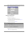
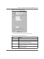
Configuring and managing ATM . . . . . . . . . . . . . . . . . . . . . . . . . . . . . . . . . . . . . . . . . 51
Changing default settings . . . . . . . . . . . . . . . . . . . . . . . . . . . . . . . . . . . . . . . . . . . 52
Resetting the module . . . . . . . . . . . . . . . . . . . . . . . . . . . . . . . . . . . . . . . . . . . . . . . 54
Viewing MDA information . . . . . . . . . . . . . . . . . . . . . . . . . . . . . . . . . . . . . . . . . . . 56
Enabling or disabling a port . . . . . . . . . . . . . . . . . . . . . . . . . . . . . . . . . . . . . . . . . . 57
Editing port parameters . . . . . . . . . . . . . . . . . . . . . . . . . . . . . . . . . . . . . . . . . . . . . 58
Editing ATM and framing parameters . . . . . . . . . . . . . . . . . . . . . . . . . . . . . . . . . . 58
Editing circuit parameters . . . . . . . . . . . . . . . . . . . . . . . . . . . . . . . . . . . . . . . . . . . 60
Deleting a PVC . . . . . . . . . . . . . . . . . . . . . . . . . . . . . . . . . . . . . . . . . . . . . . . . . . . 63
Configuring ATM 1483 ELAN parameters . . . . . . . . . . . . . . . . . . . . . . . . . . . . . . . 64
Deleting an ATM 1483 ELAN . . . . . . . . . . . . . . . . . . . . . . . . . . . . . . . . . . . . . . . . . 69
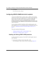
Configuring ATM F5-OAM End-to-End Loopback . . . . . . . . . . . . . . . . . . . . . . . . . . . . 70
Enabling and defining ATM F5-OAM parameters . . . . . . . . . . . . . . . . . . . . . . . . . 70
Displaying F5 Loopback statistics . . . . . . . . . . . . . . . . . . . . . . . . . . . . . . . . . . . . . 72
Displaying statistics using Device Manager . . . . . . . . . . . . . . . . . . . . . . . . . . . . . . . . . 73
Testing using Device Manager . . . . . . . . . . . . . . . . . . . . . . . . . . . . . . . . . . . . . . . . . . . 73
209195-B
Contents
9
Chapter 5
Managing the Passport 8672ATME Module
with the CLI. . . . . . . . . . . . . . . . . . . . . . . . . . . . . . . . . . . . . . . . . . . . . . . . . . . 75
Configuration commands . . . . . . . . . . . . . . . . . . . . . . . . . . . . . . . . . . . . . . . . . . . . . . . 76
Module commands . . . . . . . . . . . . . . . . . . . . . . . . . . . . . . . . . . . . . . . . . . . . . . . . . . . . 76
1483 ELAN statistics . . . . . . . . . . . . . . . . . . . . . . . . . . . . . . . . . . . . . . . . . . . . . . . . . . 77
config atmcard elan-stats . . . . . . . . . . . . . . . . . . . . . . . . . . . . . . . . . . . . . . . . . . . 77
clear atm elan-stats <vlan id> . . . . . . . . . . . . . . . . . . . . . . . . . . . . . . . . . . . . . . . . 77
show atm elan-stats <vlan id> . . . . . . . . . . . . . . . . . . . . . . . . . . . . . . . . . . . . . . . . 78
clear atm elan-stats . . . . . . . . . . . . . . . . . . . . . . . . . . . . . . . . . . . . . . . . . . . . . . . . 79
Port commands . . . . . . . . . . . . . . . . . . . . . . . . . . . . . . . . . . . . . . . . . . . . . . . . . . . . . . 79
config atm command . . . . . . . . . . . . . . . . . . . . . . . . . . . . . . . . . . . . . . . . . . . . . . . 80
config atm pvc command . . . . . . . . . . . . . . . . . . . . . . . . . . . . . . . . . . . . . . . . . . . . 81
config atm pvc 1483 command . . . . . . . . . . . . . . . . . . . . . . . . . . . . . . . . . . . . . . . 82
config atm info command . . . . . . . . . . . . . . . . . . . . . . . . . . . . . . . . . . . . . . . . . . . 84
Show commands . . . . . . . . . . . . . . . . . . . . . . . . . . . . . . . . . . . . . . . . . . . . . . . . . . . . . 85
show ports info atm all command . . . . . . . . . . . . . . . . . . . . . . . . . . . . . . . . . . . . . 85
show ports info atm fdb command . . . . . . . . . . . . . . . . . . . . . . . . . . . . . . . . . . . . . 88
show ports info atm ports command . . . . . . . . . . . . . . . . . . . . . . . . . . . . . . . . . . . 89
show ports info atm pvc command . . . . . . . . . . . . . . . . . . . . . . . . . . . . . . . . . . . . 91
show ports info atm 1483 command . . . . . . . . . . . . . . . . . . . . . . . . . . . . . . . . . . . 93
show ports stats atmport command . . . . . . . . . . . . . . . . . . . . . . . . . . . . . . . . . . . . 94
show ports stats atm felinecurrent . . . . . . . . . . . . . . . . . . . . . . . . . . . . . . . . . . . . . 96
show ports stats atm felineinterval . . . . . . . . . . . . . . . . . . . . . . . . . . . . . . . . . . . . 98
show ports stats atm fepathcurrent . . . . . . . . . . . . . . . . . . . . . . . . . . . . . . . . . . . . 99
show ports stats atm fepathinterval . . . . . . . . . . . . . . . . . . . . . . . . . . . . . . . . . . . 100
show ports stats atm linecurrent . . . . . . . . . . . . . . . . . . . . . . . . . . . . . . . . . . . . . 102
show ports stats atm lineinterval . . . . . . . . . . . . . . . . . . . . . . . . . . . . . . . . . . . . . 103
show ports stats atm pathcurrent . . . . . . . . . . . . . . . . . . . . . . . . . . . . . . . . . . . . 104
show ports stats atm pathinterval . . . . . . . . . . . . . . . . . . . . . . . . . . . . . . . . . . . . 106
show ports stats atm sectioncurrent . . . . . . . . . . . . . . . . . . . . . . . . . . . . . . . . . . 107
show ports stats atm sectioninterval . . . . . . . . . . . . . . . . . . . . . . . . . . . . . . . . . . 108
show ports stats atm sonetmediumtbl . . . . . . . . . . . . . . . . . . . . . . . . . . . . . . . . . 110
Using the Passport 8672ATME Module
10
Contents
Configuring ATM F5-OAM End-to-End Loopback . . . . . . . . . . . . . . . . . . . . . . . . . . . 111
config atm pvc f5-oam command
. . . . . . . . . . . . . 112
show ports info atm pvc [slot/port] . . . . . . . . . . . . . . . . . . . . . . . . . . . . . . . . . . . . 113
show ports info atm f5-oam [slot/port] . . . . . . . . . . . . . . . . . . . . . . . . . . . . . . . . . 114
clear atm f5-oam [slot/port] . . . . . . . . . . . . . . . . . . . . . . . . . . . . . . . . . . . . . . . . . 115
Displaying packet loss counters . . . . . . . . . . . . . . . . . . . . . . . . . . . . . . . . . . . . . . . . . 116
Chapter 6
Configuring the Passport 8672ATME Module . . . . . . . . . . . . . . . . . . . . . . 117
Initial configuration . . . . . . . . . . . . . . . . . . . . . . . . . . . . . . . . . . . . . . . . . . . . . . . . . . . 117
Changing the clock setting using Device Manager . . . . . . . . . . . . . . . . . . . . . . . 118
Changing the clock setting using the CLI . . . . . . . . . . . . . . . . . . . . . . . . . . . . . . 119
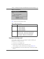
Basic configuration procedures . . . . . . . . . . . . . . . . . . . . . . . . . . . . . . . . . . . . . . . . . 120
Bridging point-to-point traffic using an ATM 1483 PVC using Device Manager . . 120
Creating a VLAN “byPort” and adding ports . . . . . . . . . . . . . . . . . . . . . . . . . 121
Configuring an ATM 1483 PVC . . . . . . . . . . . . . . . . . . . . . . . . . . . . . . . . . . . . . . 125
Associating the PVC with the VLAN . . . . . . . . . . . . . . . . . . . . . . . . . . . . . . . . . . 126
Bridging point-to-point traffic using an ATM 1483 PVC using the CLI . . . . . . . . . 127
Bridging point-to-multipoint traffic using an ATM 1483 PVC using Device Manager .
127
Configuring two ATM 1483 PVCs on the same ATM port . . . . . . . . . . . . . . . 128
Associating the PVCs with the same VLAN . . . . . . . . . . . . . . . . . . . . . . . . . 128
Bridging point-to-multipoint traffic using an ATM 1483 PVC using the CLI . . . . . 129
Configuring an IP routing 1483 PVC using Device Manager . . . . . . . . . . . . . . . . 129
Creating two VLANs “byPort” . . . . . . . . . . . . . . . . . . . . . . . . . . . . . . . . . . . . 130
Assigning IP addresses . . . . . . . . . . . . . . . . . . . . . . . . . . . . . . . . . . . . . . . . . 130
Enabling RIP routing . . . . . . . . . . . . . . . . . . . . . . . . . . . . . . . . . . . . . . . . . . . 132
Enabling OSPF routing . . . . . . . . . . . . . . . . . . . . . . . . . . . . . . . . . . . . . . . . . 134
Configuring a null-encapsulation PVC . . . . . . . . . . . . . . . . . . . . . . . . . . . . . 136
Associating the PVC with the VLAN . . . . . . . . . . . . . . . . . . . . . . . . . . . . . . . 136
Configuring an IP routing 1483 PVC using the CLI . . . . . . . . . . . . . . . . . . . . . . . 136
209195-B
Contents
11
Configuring an IPX routing 1483 PVC using Device Manager . . . . . . . . . . . . . . 137
Creating two VLANs “byPort” . . . . . . . . . . . . . . . . . . . . . . . . . . . . . . . . . . . . 138
Configuring IPX network numbers . . . . . . . . . . . . . . . . . . . . . . . . . . . . . . . . 139
Enabling IPX forwarding . . . . . . . . . . . . . . . . . . . . . . . . . . . . . . . . . . . . . . . . 140
Enabling IPX network number forwarding . . . . . . . . . . . . . . . . . . . . . . . . . . . 141
Configuring a null-encapsulation PVC . . . . . . . . . . . . . . . . . . . . . . . . . . . . . 142
Associating the PVC with the VLAN . . . . . . . . . . . . . . . . . . . . . . . . . . . . . . . 142
Configuring an IPX routing 1483 PVC using the CLI . . . . . . . . . . . . . . . . . . . . . . 143
Chapter 7
Web Management. . . . . . . . . . . . . . . . . . . . . . . . . . . . . . . . . . . . . . . . . . . . . 145
Appendix A
Technical Specifications . . . . . . . . . . . . . . . . . . . . . . . . . . . . . . . . . . . . . . . 153
Appendix B
Factory defaults . . . . . . . . . . . . . . . . . . . . . . . . . . . . . . . . . . . . . . . . . . . . . . 155
Index . . . . . . . . . . . . . . . . . . . . . . . . . . . . . . . . . . . . . . . . . . . . . . . . . . . . . . . 157
Using the Passport 8672ATME Module
12
Contents
209195-B
13
Figures
Figure 1
Passport 8672ATM module . . . . . . . . . . . . . . . . . . . . . . . . . . . . . . . . . . . 29
Figure 2
1-port OC-12c/STM-4 MDA . . . . . . . . . . . . . . . . . . . . . . . . . . . . . . . . . . . 29
Figure 3
4-port OC-3c/STM-1 MDA . . . . . . . . . . . . . . . . . . . . . . . . . . . . . . . . . . . . 30
Figure 4
Passport 8672 ATM module with OC-12c/STM-4 MDA . . . . . . . . . . . . . . 30
Figure 5
Removing the filler panel . . . . . . . . . . . . . . . . . . . . . . . . . . . . . . . . . . . . . 39
Figure 6
Extending the inserter/extractor levers . . . . . . . . . . . . . . . . . . . . . . . . . . . 39
Figure 7
Inserting the Passport 8672ATME Module . . . . . . . . . . . . . . . . . . . . . . . . 40
Figure 8
Closing the inserter/extractor levers . . . . . . . . . . . . . . . . . . . . . . . . . . . . . 40
Figure 9
Tightening the retainer screws . . . . . . . . . . . . . . . . . . . . . . . . . . . . . . . . . 41
Figure 10
Unsuccessful download screen output . . . . . . . . . . . . . . . . . . . . . . . . . . . 43
Figure 11
Passport 8000 series chassis with Passport 8672ATME Module . . . . . . . 50
Figure 12
Interface tab—ATM . . . . . . . . . . . . . . . . . . . . . . . . . . . . . . . . . . . . . . . . . . 52
Figure 13
Card tab . . . . . . . . . . . . . . . . . . . . . . . . . . . . . . . . . . . . . . . . . . . . . . . . . . 55
Figure 14
ATM tab . . . . . . . . . . . . . . . . . . . . . . . . . . . . . . . . . . . . . . . . . . . . . . . . . . 56
Figure 15
MDA dialog box . . . . . . . . . . . . . . . . . . . . . . . . . . . . . . . . . . . . . . . . . . . . 57
Figure 16
ATM tab . . . . . . . . . . . . . . . . . . . . . . . . . . . . . . . . . . . . . . . . . . . . . . . . . . 59
Figure 17
ATM PVC tab . . . . . . . . . . . . . . . . . . . . . . . . . . . . . . . . . . . . . . . . . . . . . . 61
Figure 18
Insert ATM PVC dialog box . . . . . . . . . . . . . . . . . . . . . . . . . . . . . . . . . . . . 62
Figure 19
ATM PVC tab with a PVC selected . . . . . . . . . . . . . . . . . . . . . . . . . . . . . . 64
Figure 20
ATM 1483 ELAN tab . . . . . . . . . . . . . . . . . . . . . . . . . . . . . . . . . . . . . . . . . 64
Figure 21
Port, Insert ATM 1483 ELAN dialog box . . . . . . . . . . . . . . . . . . . . . . . . . . 66
Figure 22
Insert ATM 1483 ELAN dialog box for IP routing . . . . . . . . . . . . . . . . . . . 68
Figure 23
Insert ATM 1483 ELAN dialog box for IPX routing . . . . . . . . . . . . . . . . . . 69
Figure 24
ATM 1483 ELAN tab with ElanId selected . . . . . . . . . . . . . . . . . . . . . . . . 69
Figure 25
ATM PVC dialog box—ATM PVC tab . . . . . . . . . . . . . . . . . . . . . . . . . . . . 71
Figure 26
F5 Loopback dialog box . . . . . . . . . . . . . . . . . . . . . . . . . . . . . . . . . . . . . . 71
Figure 27
F5 Loopback Stats tab . . . . . . . . . . . . . . . . . . . . . . . . . . . . . . . . . . . . . . . 72
Figure 28
show atm elan-stats command output . . . . . . . . . . . . . . . . . . . . . . . . . . . 78
Figure 29
Sample output for the config atm info command . . . . . . . . . . . . . . . . . . . 84
Using the Passport 8672ATME Module
14
Figures
Figure 30
show ports info atm all command output . . . . . . . . . . . . . . . . . . . . . . . . . 86
Figure 31
show ports info atm fdb command output . . . . . . . . . . . . . . . . . . . . . . . . 89
Figure 32
show ports info atm ports command output . . . . . . . . . . . . . . . . . . . . . . . 90
Figure 33
show ports info atm pvc command output . . . . . . . . . . . . . . . . . . . . . . . . 92
Figure 34
show ports info atm 1483 command output . . . . . . . . . . . . . . . . . . . . . . . 93
Figure 35
show ports stats atmport [<port num>] command output . . . . . . . . . . . . . 95
Figure 36
show ports stats atm felinecurrent command output . . . . . . . . . . . . . . . . 97
Figure 37
show ports stats atm felineinterval command output . . . . . . . . . . . . . . . . 98
Figure 38
show ports stats atm fepathcurrent command output . . . . . . . . . . . . . . . 99
Figure 39
show ports stats atm fepathinterval command output . . . . . . . . . . . . . . 101
Figure 40
show ports stats atm linecurrent command output . . . . . . . . . . . . . . . . 102
Figure 41
show ports stats atm lineinterval command output . . . . . . . . . . . . . . . . . 103
Figure 42
show ports stats atm pathcurrent command output . . . . . . . . . . . . . . . . 105
Figure 43
show ports stats atm pathinterval command output . . . . . . . . . . . . . . . 106
Figure 44
show ports stats atm sectioncurrent command output . . . . . . . . . . . . . 107
Figure 45
show ports stats atm sectioninterval command output . . . . . . . . . . . . . 109
Figure 46
show ports stats atm sonetmediumtbl command output . . . . . . . . . . . . 110
Figure 47
Sample output for the show ports info atm
pvc [slot/port] command . . . . . . . . . . . . . . . . . . . . . . . . . . . . . . . . 114
Figure 48
Sample output of the show ports info atm
f5-oam [slot/port] command . . . . . . . . . . . . . . . . . . . . . . . . . . . . 114
Figure 49
ATM tab . . . . . . . . . . . . . . . . . . . . . . . . . . . . . . . . . . . . . . . . . . . . . . . . . 119
Figure 50
Point-to-point bridging using 1483 PVCs . . . . . . . . . . . . . . . . . . . . . . . . 121
Figure 51
Basic tab . . . . . . . . . . . . . . . . . . . . . . . . . . . . . . . . . . . . . . . . . . . . . . . . . 121
Figure 52
VLAN, Insert Basic dialog box . . . . . . . . . . . . . . . . . . . . . . . . . . . . . . . . 123
Figure 53
VlanPortMembers dialog box . . . . . . . . . . . . . . . . . . . . . . . . . . . . . . . . . 124
Figure 54
Point-to-multipoint bridging using ATM 1483 PVCs . . . . . . . . . . . . . . . . 128
Figure 55
IP routing with ATM 1483 PVCs . . . . . . . . . . . . . . . . . . . . . . . . . . . . . . . 130
Figure 56
IP Address tab . . . . . . . . . . . . . . . . . . . . . . . . . . . . . . . . . . . . . . . . . . . . 131
Figure 57
IP, VLAN, Insert IP Address dialog box . . . . . . . . . . . . . . . . . . . . . . . . . 131
Figure 58
RIP tab . . . . . . . . . . . . . . . . . . . . . . . . . . . . . . . . . . . . . . . . . . . . . . . . . . 133
Figure 59
OSPF tab . . . . . . . . . . . . . . . . . . . . . . . . . . . . . . . . . . . . . . . . . . . . . . . . 135
Figure 60
IPX routing with ATM 1483 PVCs . . . . . . . . . . . . . . . . . . . . . . . . . . . . . . 138
Figure 61
IPX VLAN dialog box . . . . . . . . . . . . . . . . . . . . . . . . . . . . . . . . . . . . . . . 139
Figure 62
IPX VLAN, Insert dialog box . . . . . . . . . . . . . . . . . . . . . . . . . . . . . . . . . . 140
Figure 63
Globals tab . . . . . . . . . . . . . . . . . . . . . . . . . . . . . . . . . . . . . . . . . . . . . . . 140
209195-B
Figures
15
Figure 64
Circuits tab . . . . . . . . . . . . . . . . . . . . . . . . . . . . . . . . . . . . . . . . . . . . . . . 141
Figure 65
System page . . . . . . . . . . . . . . . . . . . . . . . . . . . . . . . . . . . . . . . . . . . . . . 146
Figure 66
ATM menu . . . . . . . . . . . . . . . . . . . . . . . . . . . . . . . . . . . . . . . . . . . . . . . 147
Figure 67
PVC page . . . . . . . . . . . . . . . . . . . . . . . . . . . . . . . . . . . . . . . . . . . . . . . . 148
Figure 68
1483 ELAN page, (left section) . . . . . . . . . . . . . . . . . . . . . . . . . . . . . . . . 149
Figure 69
1483 ELAN page, (right section) . . . . . . . . . . . . . . . . . . . . . . . . . . . . . . 149
Figure 70
Port page . . . . . . . . . . . . . . . . . . . . . . . . . . . . . . . . . . . . . . . . . . . . . . . . 151
Using the Passport 8672ATME Module
16
Figures
209195-B
17
Tables
Table 1
Passport 8672ATME Module online LED indications . . . . . . . . . . . . . . . . 31
Table 2
MDA LED indications . . . . . . . . . . . . . . . . . . . . . . . . . . . . . . . . . . . . . . . . 31
Table 3
Device Manager port color codes . . . . . . . . . . . . . . . . . . . . . . . . . . . . . . . 50
Table 4
Device Manager buttons . . . . . . . . . . . . . . . . . . . . . . . . . . . . . . . . . . . . . . 51
Table 5
ATM Interface tab fields . . . . . . . . . . . . . . . . . . . . . . . . . . . . . . . . . . . . . . 53
Table 6
Card tab fields . . . . . . . . . . . . . . . . . . . . . . . . . . . . . . . . . . . . . . . . . . . . . 55
Table 7
MDA dialog box fields . . . . . . . . . . . . . . . . . . . . . . . . . . . . . . . . . . . . . . . . 57
Table 8
ATM tab fields . . . . . . . . . . . . . . . . . . . . . . . . . . . . . . . . . . . . . . . . . . . . . 59
Table 9
ATM PVC tab fields . . . . . . . . . . . . . . . . . . . . . . . . . . . . . . . . . . . . . . . . . 61
Table 10
Insert ATM PVC dialog box fields . . . . . . . . . . . . . . . . . . . . . . . . . . . . . . . 62
Table 11
ATM 1483 ELAN tab fields . . . . . . . . . . . . . . . . . . . . . . . . . . . . . . . . . . . . 65
Table 12
Port, Insert ATM 1483 ELAN dialog box fields . . . . . . . . . . . . . . . . . . . . . 66
Table 13
F5 Loopback tab field descriptions . . . . . . . . . . . . . . . . . . . . . . . . . . . . . . 71
Table 14
F5 Loopback Stats tab fields . . . . . . . . . . . . . . . . . . . . . . . . . . . . . . . . . . 73
Table 15
config atmcard command parameters and variables . . . . . . . . . . . . . . . . 77
Table 16
Information fields for the show atm elan-stats command . . . . . . . . . . . . . 78
Table 17
config atm command parameters and variables . . . . . . . . . . . . . . . . . . . . 80
Table 18
config atm pvc command parameters and variables . . . . . . . . . . . . . . . . 81
Table 19
config atm pvc 1483 bridged command parameters and variables . . . . . 82
Table 20
config atm pvc 1483 ip command parameters and variables . . . . . . . . . . 83
Table 21
config atm pvc 1483 ipx command parameters and variables . . . . . . . . . 84
Table 22
Information fields for the show ports info atm all command . . . . . . . . . . . 87
Table 23
Information fields for the show ports info atm fdb command . . . . . . . . . . 89
Table 24
Information fields for the show ports info atm ports
command . . . . . . . . . . . . . . . . . . . . . . . . . . . . . . . . . . . . . . . . . . . . . . . . . 90
Table 25
Information fields for the show ports info atm pvc command . . . . . . . . . . 92
Table 26
Information fields for the show ports info atm 1483
command . . . . . . . . . . . . . . . . . . . . . . . . . . . . . . . . . . . . . . . . . . . . . . . . . 93
Table 27
Information fields for the show ports stats atmport
command . . . . . . . . . . . . . . . . . . . . . . . . . . . . . . . . . . . . . . . . . . . . . . . . . 95
Using the Passport 8672ATME Module
18
Tables
Table 28
Information fields for the show ports stats atm felinecurrent command . . 97
Table 29
Information fields for the show ports stats atm felineinterval
command . . . . . . . . . . . . . . . . . . . . . . . . . . . . . . . . . . . . . . . . . . . . . . . . . 98
Table 30
Information fields for the show ports stats atm fepathcurrent command 100
Table 31
Information fields for the show ports stats atm fepathinterval command 101
Table 32
Information fields for the show ports stats atm linecurrent
command . . . . . . . . . . . . . . . . . . . . . . . . . . . . . . . . . . . . . . . . . . . . . . . . 102
Table 33
Information fields for The show ports stats atm lineinterval command . 104
Table 34
Information fields for the show ports stats atm pathcurrent command . 105
Table 35
Information fields for the show ports stats atm pathinterval
command . . . . . . . . . . . . . . . . . . . . . . . . . . . . . . . . . . . . . . . . . . . . . . . . 106
Table 36
Information fields for the show ports stats atm sectioncurrent command 108
Table 37
Information fields for the show ports stats atm sectioninterval command 109
Table 38
Information fields for output of the show ports stats atm sonetmediumtbl
command . . . . . . . . . . . . . . . . . . . . . . . . . . . . . . . . . . . . . . . . . . . . . . . . 110
Table 39
F5-OAM Loopback parameters . . . . . . . . . . . . . . . . . . . . . . . . . . . . . . . 112
Table 40
Status and statistic definition . . . . . . . . . . . . . . . . . . . . . . . . . . . . . . . . . 115
Table 41
Sample output for the sh ports stats interface
main command . . . . . . . . . . . . . . . . . . . . . . . . . . . . . . . . . . . . . . . . . . . 116
Table 42
Basic tab fields
Table 43
VLAN, Insert Basic dialog box fields . . . . . . . . . . . . . . . . . . . . . . . . . . . . 123
Table 44
VlanPortMembers dialog box fields . . . . . . . . . . . . . . . . . . . . . . . . . . . . 124
Table 45
IP Address tab fields . . . . . . . . . . . . . . . . . . . . . . . . . . . . . . . . . . . . . . . . 131
Table 46
IP, VLAN, Insert IP Address dialog box fields . . . . . . . . . . . . . . . . . . . . . 132
Table 47
RIP tab fields . . . . . . . . . . . . . . . . . . . . . . . . . . . . . . . . . . . . . . . . . . . . . 133
Table 48
OSPF tab fields . . . . . . . . . . . . . . . . . . . . . . . . . . . . . . . . . . . . . . . . . . . 135
Table 49
IPX VLAN dialog box fields . . . . . . . . . . . . . . . . . . . . . . . . . . . . . . . . . . . 139
Table 50
IPX VLAN, Insert dialog box fields . . . . . . . . . . . . . . . . . . . . . . . . . . . . . 140
Table 51
Globals tab item . . . . . . . . . . . . . . . . . . . . . . . . . . . . . . . . . . . . . . . . . . . 141
Table 52
Circuits tab fields . . . . . . . . . . . . . . . . . . . . . . . . . . . . . . . . . . . . . . . . . . 142
Table 53
System page fields
Table 54
PVC page items . . . . . . . . . . . . . . . . . . . . . . . . . . . . . . . . . . . . . . . . . . . 148
Table 55
1483 ELAN page items . . . . . . . . . . . . . . . . . . . . . . . . . . . . . . . . . . . . . . 150
Table 56
Port page items . . . . . . . . . . . . . . . . . . . . . . . . . . . . . . . . . . . . . . . . . . . 151
Table 57
Factory default settings for the Passport 8672ATME Module . . . . . . . . . 155
209195-B
. . . . . . . . . . . . . . . . . . . . . . . . . . . . . . . . . . . . . . . . . . . 122
. . . . . . . . . . . . . . . . . . . . . . . . . . . . . . . . . . . . . . . . 146
19
Preface
The Passport® 8672ATME Module is part of the Nortel Networks Passport line of
communications products. This module is the Passport Asynchronous Transfer
Mode (ATM) module for the Passport 8600 chassis. This guide describes the
features and operations of the module and provides instructions for installing and
managing the module.
Before you begin
This guide is intended for network installers and system administrators who are
responsible for installing, configuring, or maintaining networks. This guide
assumes that you have the following background:
•
•
Understanding of the transmission and management protocols used on your
network
Experience with windowing systems or graphical user interfaces (GUIs)
Using the Passport 8672ATME Module
20
Preface
Text conventions
This guide uses the following text conventions:
angle brackets (< >)
Indicate that you choose the text to enter based on the
description inside the brackets. Do not type the
brackets when entering the command.
Example: If the command syntax is
ping <ip_address>, you enter
ping 192.32.10.12
bold Courier text
Indicates command names and options and text that
you need to enter.
Example: Use the dinfo command.
Example: Enter show ip {alerts|routes}.
braces ({})
Indicate required elements in syntax descriptions where
there is more than one option. You must choose only
one of the options. Do not type the braces when
entering the command.
Example: If the command syntax is
show ip {alerts|routes}, you must enter either
show ip alerts or show ip routes, but not both.
brackets ([ ])
Indicate optional elements in syntax descriptions. Do
not type the brackets when entering the command.
Example: If the command syntax is
show ip interfaces [-alerts], you can enter
either show ip interfaces or
show ip interfaces -alerts.
ellipsis points (. . . )
Indicate that you repeat the last element of the
command as needed.
Example: If the command syntax is
ethernet/2/1 [<parameter> <value>]... ,
you enter ethernet/2/1 and as many
parameter-value pairs as needed.
209195-B
Preface
21
italic text
Indicates new terms, book titles, and variables in
command syntax descriptions. Where a variable is two
or more words, the words are connected by an
underscore.
Example: If the command syntax is
show at <valid_route>, valid_route is one
variable and you substitute one value for it.
plain Courier
text
Indicates command syntax and system output, for
example, prompts and system messages.
Example: Set Trap Monitor Filters
separator ( > )
Shows menu paths.
Example: Protocols > IP identifies the IP option on the
Protocols menu.
vertical line ( | )
Separates choices for command keywords and
arguments. Enter only one of the choices. Do not type
the vertical line when entering the command.
Example: If the command syntax is
show ip {alerts|routes}, you enter either
show ip alerts or show ip routes, but not
both.
Related publications
For more information about using a Passport 8000 Series switch, the resident CLI,
or Device Manager, refer to the following publications:
•
Release Notes for the Passport 8000 Series Switch Release 3.2 (part number
313198-B Rev 00)
Provides a list of new features and late-breaking information about the
hardware and software that is not included in the Passport 8000 Series switch
documentation.
Using the Passport 8672ATME Module
22
Preface
•
Installing and Maintaining the Passport 8003 Chassis and Components
(part number 313074-B Rev 00)
Provides instructions for installing the Passport 8003 Chassis in an equipment
rack and for installing and replacing fan trays, power supplies, modules,
gigabit interface converters, and media dependent adapters. This guide
describes some of the routine tasks of operating the Passport 8003 Chassis and
includes technical specifications for the chassis and the modules.
•
Installing and Maintaining the Passport 8006 Chassis and Components
(part number 312748-B Rev 00)
Provides instructions for installing the Passport 8006 Chassis in an equipment
rack and for installing and replacing fan trays, power supplies, modules,
gigabit interface converters, and media dependent adapters. This guide
describes some of the routine tasks of operating the Passport 8006 Chassis and
includes technical specifications for the chassis and the modules.
•
Installing and Maintaining the Passport 8010 Chassis and Components
(part number 312747-B Rev 00)
Provides instructions for installing the Passport 8010 Chassis in an equipment
rack and for installing and replacing fan trays, power supplies, modules,
gigabit interface converters, and media dependent adapters. This guide
describes some of the routine tasks of operating the Passport 8010 Chassis and
includes technical specifications for the chassis and the modules.
•
Installing and Maintaining the Passport 8010co Chassis and Components
(part number 312746-B Rev 00)
Provides instructions for installing the Passport 8010co Chassis in an
equipment rack and for installing and replacing fan trays, power supplies,
modules, gigabit interface converters, and media dependent adapters. This
guide describes some of the routine tasks of operating the Passport 8010co
Chassis and includes technical specifications for the chassis and the modules.
•
Installing the Breaker Interface Panel for the Passport 8010co Chassis
(part number 312755-B Rev 00)
Describes how to install the breaker interface panel in an equipment rack,
connect cables, and interpret LEDs. It includes technical specifications for the
breaker interface panel.
209195-B
Preface
•
23
Networking Concepts for the Passport 8000 Series Switch (part number
313196-B Rev 00)
Provides general information and a description of how a Passport 8000 Series
switch handles various networking features, such as VLANs, MultiLink
Trunking, OSPF, RIP, and IPX.
•
Network Design Guidelines for the Passport 8000 Series Switch (part number
313197-B Rev 00)
Provides guidelines for using the switching and routing features of the
Passport 8000 Series hardware and software in your network design. This
companion guide to Networking Concepts for the Passport 8000 Series Switch
incorporates feedback from beta testing of the switch and focuses on
optimizing network performance.
•
Getting Started with the Passport 8000 Series Switch Management Software
(part number 313189-B Rev 00)
Provides instructions for installing the Passport 8000 Series switch
management software and describes initial setup procedures.
•
Managing the Passport 8000 Series Switch Using the Command Line
Interface Release 3.2 (part number 313194-B Rev 00)
Describes the command line interface (CLI) structure and the commands used
to perform basic switch management operations, such as modifying the switch
boot sequence, working with switch files, and setting up security features.
•
Configuring Switching Operations for the Passport 8000 Series Switch Using
the Command Line Interface Release 3.1.2 (part number 313191-B Rev 00)
Describes the CLI commands and parameters for configuring layer 2
(switching) and layer 3 (routing) operations.
•
Managing the Passport 8000 Series Switch Using Device Manager Release
5.x.x (part number 313195-B Rev 00)
Describes the structure of Device Manager and how to use it to perform basic
switch management operations, such as working with switch files and setting
up security features.
•
Configuring Switching and Routing Operations for the Passport 8000 Series
Switch Using Device Manager Release 5.x.x (part number 313193-B Rev 00)
Describes how to use Device Manager to configure and manage layer 2
(switching) and layer 3 (routing) functions.
Using the Passport 8672ATME Module
24
Preface
You can print selected technical manuals and release notes free, directly from the
Internet. Go to the www.nortelnetworks.com/documentation URL. Find the
product for which you need documentation. Then locate the specific category and
model or version for your hardware or software product. Use Adobe* Acrobat
Reader* to open the manuals and release notes, search for the sections you need,
and print them on most standard printers. Go to Adobe Systems at the
www.adobe.com URL to download a free copy of the Adobe Acrobat Reader.
You can purchase selected documentation sets, CDs, and technical publications
through the Internet at the www1.fatbrain.com/documentation/nortel/ URL.
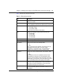
How to get help
If you purchased a service contract for your Nortel Networks product from a
distributor or authorized reseller, contact the technical support staff for that
distributor or reseller for assistance.
If you purchased a Nortel Networks service program, contact one of the following
Nortel Networks Technical Solutions Centers:
Technical Solutions Center
Telephone
Europe, Middle East, and Africa
(33) (4) 92-966-968
North America
(800) 4NORTEL or (800) 466-7835
Asia Pacific
(61) (2) 9927-8800
China
(800) 810-5000
Additional information about the Nortel Networks Technical Solutions Centers is
available from the www.nortelnetworks.com/help/contact/global URL.
An Express Routing Code (ERC) is available for many Nortel Networks products
and services. When you use an ERC, your call is routed to a technical support
person who specializes in supporting that product or service. To locate an ERC for
your product or service, go to the http://www130.nortelnetworks.com/cgi-bin/
eserv/common/essContactUs.jsp URL.
209195-B
25
Chapter 1
About the Passport 8672ATME Module
The Passport 8672ATME Module provides network transmission using ATM
technology. The Passport 8672ATME Module enables MAN/WAN/campus
connectivity for the Passport 8600 Routing Switch with the capability to
interconnect frame-switched networks using a backbone ATM network. The
module also provides existing ATM customers with the capability for connectivity
to the Passport 8600 Routing Switch. (For more information on ATM, refer to the
ATM Forum Web site at the http://www.atmforum.com URL.)
The Passport 8672ATME Module occupies a single slot in a Passport 8600 series
chassis. The module is a baseboard with room for two of the following optional
Media dependent adapters (MDAs):
•
•
1-port OC-12c/STM-4: single-mode fiber (SMF) or multimode fiber (MMF)
using the Synchronous Optical Network (SONET/SDH) media
4-port OC-3c/STM-1: SMF or MMF using SONET/SDH media
The Passport 8672ATME Module for the Passport 8000 series chassis can be used
as an edge device for WAN connectivity in the data center; it is used to connect
Passport 8600 to public or private ATM networks. You can also use the
Passport 8672ATME Module in the wiring closet in inter-building connection
technology in campus networks where each building is supported by
frame-switched networks.
Another network application of the Passport 8672ATME Module is a direct
connection between one Passport 8600 series switch with a Passport 8672ATME
Module in one building to an identical module in another Passport 8600 Series
switch at another building. You connect the switches with a dedicated fiber link or
with a SONET multiplex network. Each building may be individually supported
by either frame-switched or ATM technology.
Using the Passport 8672ATME Module
26
Chapter 1 About the Passport 8672ATME Module
You can use up to two Passport 8672ATME Modules in one Passport 8600 series
chassis.
Refer to Networking Concepts for the Passport 8000 Series Switch for a thorough
discussion of the complete functionality of the Passport 8000 series product line,
including the Passport 8672ATME Module. Note that VRRP, DiffServ, and ATM
QoS are not supported on this module.
This chapter provides the following information about the Passport 8672ATME
Module:
•
•
“Features” next
“Physical description” on page 28
Features
The Passport 8672ATME Module has the following features:
•
•
•
•
•
•
•
•
•
•
•
•
209195-B
RFC 1483 ATM PVC support
— Bridged PVC
— IP routed PVC
— IPX routed PVC
Both RFC 1483 LLC/SNAP encapsulation and Null encapsulation
RFC 1483 point-to-multipoint bridging—up to 64 PVCs per ELAN
MLT using bridged RFC 1483 PVCs
VBR traffic shaping per VC channel
STP support
F5 OAM end-to-end loopback
SONET statistics and ELAN/PORT level statistics
Front-panel Online LED to monitor module operation
Ability to remove and install a module (hot-swap) without resetting the switch
(MDAs are not hot-swappable)
AAL 5
Hardware diagnostics
Chapter 1 About the Passport 8672ATME Module
•
•
•
27
Proprietary MIB support for configuration of RFC 1483 and ATM port
specific setup
Manageable through the Passport CLI or Device Manager, the SNMP-based
graphical interface
Monitored through a World Wide Web browser from anywhere on the
network.
ATM ELANs, and Ethernet VLANs
The Passport 8672ATME Module supports ATM Forum Emulated LANs
(ELANs). An ELAN extends an Ethernet VLAN, which is a broadcast domain,
over an ATM network.
In general, there is a one-to-one mapping between an ATM ELAN and an Ethernet
VLAN. An ATM ELAN never spans more than one ATM port because the
software considers each ATM port completely separate.
The Passport 8672ATME Module participates in ELANs as RFC 1483 PVCs.
Only Ethernet ELANs are supported on this module.
If you delete a VLAN, you delete 1483 ELANs associated with the VLAN.
Virtual network router
Virtual network router (VNR) refers to the routing functions between two ATM
virtual/emulated networks. You can use the Passport 8672ATME Module as an IPand IPX-optimized VNR.
Traffic shaping
The Passport 8672ATME Module provides per channel traffic shaping and
supports unspecified bit rate (UBR) and variable bit rate (VBR). Channels with a
specified cell rate are called rate-shaped channels.
Using the Passport 8672ATME Module
28
Chapter 1 About the Passport 8672ATME Module
The VBR service provided by the 8672 module allows a previously idle channel to
burst at a relatively high Peak Cell Rate (PCR) for a Maximum Burst Size (MBS)
of ATM cells. If the channel exhausts its MBS, the module reduces the channel’s
rate to a Sustained Cell Rate (SCR). When the channel stops transmitting, it
accumulates credit towards another burst at PCR.
The 8672 module also provides a UBR service for Transmitter channels. When a
UBR channel is opened, there is no channel rate specified. All active UBR
channels are serviced in a round-robin queue. If no rate-shaped channel is
scheduled for transmission, a single cell is sent from the channel at the head of the
UBR queue.
RFC 1483 Support
The system software on the Passport 8672ATME Module supports the
configuration of RFC 1483 LAN clients with multiprotocol encapsulation. RFC
1483 supports standards-based methods of encapsulation that enable connectivity
with third-party ATM devices. Multiprotocol encapsulation provides the
capability to set up PVCs between Centillion ATM virtual ports (VPorts) and
other clients based on LLC encapsulation. The current Centillion platform only
supports bridged variations of RFC 1483.
The Passport 8672ATME Module supports the following types of RFC 1483
ELANs:
•
•
RFC 1483 bridged 802.3. The links can be set up within a single device or
with another switch. Multiple RFC 1483 links can be set up within one
ELAN. Both LLC and NULL encapsulation are supported.
RFC 1483 routed IP and IPX. An RFC 1483 routed VLAN always contains
only one PVC, corresponding to a point-to-point link between routers. The
software adds and removes the MAC header, as appropriate. When
configuring an IP and IPX routed circuit, the ATM port must be the only port
assigned to the VLAN.
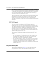
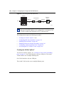
Physical description
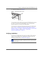
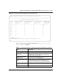
The Passport 8672ATME Module (Figure 1) is a single-slot module for the
Passport 8600 Series chassis. Online LEDs indicate module operation.
209195-B
Chapter 1 About the Passport 8672ATME Module
29
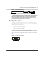
Figure 1 Passport 8672ATM module
8672 ATM
MDA 1
MDA 2
Online
9901EA
To configure and manage the Passport 8672ATME Module, connect to the console
port of your switch fabric module (either the Passport 8690SF Module or the
Passport 8691SF Module). For information on connecting to the console port,
refer to the installation guide that came with your switch.
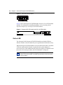
Media dependent adapters
The Passport 8672ATME Module has space for two media dependent adapters
MDAs) that have their own LEDs. You can use up to two of the following MDAs
with the Passport 8672ATME Module:
•
•
1-port OC-12c/STM-4: SMF or MMF
4-port OC-3c/STM-1: SMF or MMF
You can mix these MDAs on the Passport 8672ATME Module. Contact your
Nortel Networks representative for other MDAs that are available for this product.
Figure 2 shows the OC-12c/STM-4 MDA, and Figure 3 shows the OC-3c/STM-1
MDA.
Figure 2 1-port OC-12c/STM-4 MDA
9725EA
Using the Passport 8672ATME Module
30
Chapter 1 About the Passport 8672ATME Module
Figure 3 4-port OC-3c/STM-1 MDA
9726EA
Figure 4 shows the Passport 8672ATME Module with one OC-12c/STM-4 MDA
installed. For information on installing the MDAs, refer to Installing Media
Dependent Adapters for the Passport 8672ATME Module.
Figure 4 Passport 8672 ATM module with OC-12c/STM-4 MDA
8672 ATM
MDA 1
MDA 2
Online
9724EA
Online LED
The front panel of the Passport 8672ATME Module has an Online LED that
indicates whether or not the module has power applied and is initialized correctly.
When the Passport 8672ATME Module is first inserted into the chassis, the Online
LED turns amber until the board is recognized by the system and passes a
power-on self-test. If the module fails the self-test, the light is off. When the board
passes the self-test and goes online, the LED illuminates a solid green.
Note: You cannot configure the Passport 8672ATME Module until the
online LED on the module is steadily lit green and you have inserted at
least one MDA.
209195-B
Chapter 1 About the Passport 8672ATME Module
31
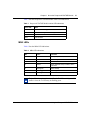
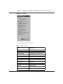
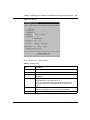
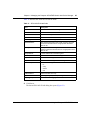
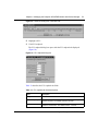
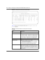
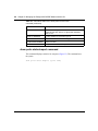
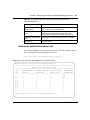
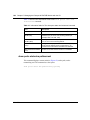
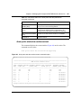
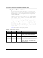
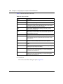
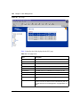
Table 1 lists the Passport 8672ATME Module online LED indications.
Table 1 Passport 8672ATME Module online LED indications
Online LED
State
Off
Card is not receiving power.
Amber
Card is initializing or downloading.
Amber
Card is offline.
Green
Card is online.
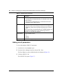
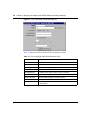
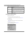
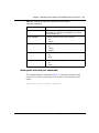
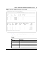
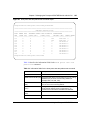
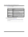
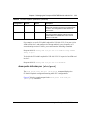
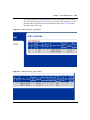
MDA LEDs
Table 2 lists the MDA LED indications.
Table 2 MDA LED indications
LED
Color
Port State
Tx
Amber
Alarm (RDI) condition, admin state down
Tx
Green
Transmitting data
Tx
Off
No traffic, no alarm
Rx
Amber
Alarm (OOF/LOF/LOS) condition, admin
state down
Rx
Solid green
Admin stateup
Rx
Flashing green
Receiving data
Tx and Rx
Flashing amber
Admin state down, out of order
Note: When there is continuous traffic, the Tx LED is solid green. If
traffic is slow, the Tx LED may be flashing green.
Using the Passport 8672ATME Module
32
Chapter 1 About the Passport 8672ATME Module
Console and Diag ports
Use the Console port on the Passport 8690SF or Passport 8691SF module to
access management functions for the Passport 8672ATME Module. For
information on connecting to the Console port of either module, refer to Getting
Started with the Passport 8000 Series Switch Management Software.
The Diag port on the Passport 8672ATME Module is used only by Nortel
Networks personnel for debugging purposes. You can see diagnostic messages but
you cannot input any text.
209195-B
33
Chapter 2
Passport 8672ATME Module terminology
This chapter contains the following information:
•
•
•
“ATM terms and acronyms,” next
“SONET terms and acronyms” on page 35
“SONET transmission rates” on page 36
ATM terms and acronyms
Asynchronous transfer mode (ATM) is a connection-oriented, cell-based
technology that relays traffic across a network. ATM provides a cost-effective way
of transmitting voice, video, and data across a network at high speeds. It offers
topology-independent, resilient networking technology.
An ATM cell is a fixed-length packet of 53 bytes. It consists of a 5-byte header
containing address information and a fixed 48-byte information field. The
fixed-length cell size allows you to predict network delays.
The following terms and acronyms are frequently used with ATM information:
•
•
ATM: Asynchronous transfer mode. ATM is a switched, connection-oriented,
fixed-length, cell-based transmission method specifically designed to run at
high data rates and to carry a complete range of user traffic, including voice,
data, and video. ATM uses dedicated media connections running in parallel,
allowing simultaneous multiple connections through a single switch device at
very high speeds.
PVC: Permanent virtual circuit. Dedicated connection between devices that is
manually set up.
Using the Passport 8672ATME Module
34
Chapter 2 Passport 8672ATME Module terminology
•
•
•
•
•
•
•
•
•
•
•
SVC: Switched virtual circuit. On-demand connection between an ATM or
frame relay source and destination that lasts for the duration of the
transmission.
VC: Virtual circuit. This is a network service that provides
connection-oriented service regardless of the underlying network structure.
VP: Virtual path. A virtual path is a set of virtual channels between a common
source and destination. The virtual channels in a virtual path are logically
associated with a common identifier, the virtual path identifier.
VPI: Virtual path identifier. Identifier contained in the ATM cell header to
designate the virtual path on the physical ATM link.
VCI: Virtual circuit identifier. Address or label contained in the ATM cell
header to designate the virtual circuit within the virtual path on the physical
ATM link
ELAN: Emulated LAN. Following the ATM Forum specification, ELANs
make connection-oriented ATM networks look like connectionless LANs.
UBR: Unspecified bit rate. UBR is an ATM service category that does not
specify traffic-related service guarantees. No numerical commitments are
made with respect to the cell loss ratio or to the cell transfer delay.
VBR: Variable bit rate. VBR is an ATM Forum-defined service category that
supports variable bit rate data traffic with average and peak traffic parameters.
PCR: Peak cell rate. The PCR, in cells/second, is the maximum cell rate.
SCR: Sustainable cell rate. The SCR is an upper bound on the cell rate that is
long relative to that of the PCR. Enforcement of this bound by the Usage
Parameter Control allows the network to allocate sufficient resources, but less
than those for the PCR, to ensure that the specified cell loss ratio can be
achieved.
MBS: Maximum burst size. The signaling method determines the MBS,
which is coded as a number of cells, that can be transmitted at peak rate and
still conform to the overall algorithm.
Data transmission (also called cell switching) through the ATM network relies on
establishing logical connections between ATM devices. ATM is a
connection-oriented service, which means that an ATM device cannot transmit
information until it establishes a connection with a receiving device.
209195-B
Chapter 2 Passport 8672ATME Module terminology
35
SONET terms and acronyms
This section provides a brief listing of common Synchronous Optical Network
(SONET) terms. SONET is a medium for transmitting data that uses fiber optic
cables.
The following terms and acronyms are frequently used with SONET information:
•
•
•
•
•
•
SONET: Synchronous Optical Network. SONET is a family of fiber optic
transmission rates that provides the flexibility to transport many digital
signals with different capacities. This ANSI standard provides for
transmission from OC-1 to OC-48 and greater.
SDH: Synchronous Digital Hierarchy. SDH is a standard technology for
optical fiber-based synchronous data transmission. SDH is the international
equivalent of SONET.
OC-3: Optical Carrier-level 3. OC-3 is an optical fiber transmission system at
155 Mb/s.
OC-3c/STM-1: Optical Carrier-level 3 concatenation. OC-3c/STM-1 is an
optical fiber transmission system that carries STS-3c/STM-1 frame structures
at 155 Mb/s. Concatenation refers to the fact that there is only one logical data
stream (rather than supporting a channelized structure).
OC-12: Optical Carrier-level 12. OC-12 is an optical fiber transmission
system at 622 Mb/s.
OC-12c/STM-4: Optical Carrier-level 12 concatenation. OC-12c/STM-4 is an
optical fiber transmission system that carries STS-12c/STM-4 frame
structures at 622 Mb/s. Concatenation refers to the fact that there is only one
logical data stream (rather than supporting a channelized structure).
Using the Passport 8672ATME Module
36
Chapter 2 Passport 8672ATME Module terminology
SONET transmission rates
The following transmission rates are commonly used with SONET:
•
•
OC-3c/STM-1: 155.52 Mb/s (and SDH/STM-1)
OC-12c/STM-4: 622.08 Mb/s (and SDH/STM-4)
The SONET specification defines optical both as:
•
•
Single-mode fiber (SMF)
Multimode fiber (MMF)
Note: The estimated maximum transmission distance for OC-3c SMF is
20 kilometers (km); for OC-3c MMF is 2 km; for OC-12c SMF is 15 km;
for OC-12c MMF is 500 m.
209195-B
37
Chapter 3
Installing the Passport 8672ATME Module
This chapter describes the procedure for installing the Passport 8672ATME
Module. It covers the following topics:
•
•
•
•
•
•
“Safety and environmental precautions,” next
“Installing the Passport 8672ATME Module” on page 39
“Verifying installation” on page 41
“Initialization” on page 42
“MDA insertion and configuration” on page 44
“Replacing a module” on page 45
For more information about the Passport 8600 chassis, refer to the following
documents:
•
•
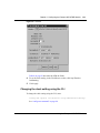
Getting Started with Passport 8000 Series Management Software
Installing the Passport 8600 Modules
Safety and environmental precautions
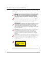
Before you begin performing any installation or replacement procedure on the
Passport switch, please note the following safe handling guidelines:
•
To prevent damage caused by electrostatic discharge (ESD), handle the switch
chassis and modules only when you, the chassis, and the chassis modules are
properly grounded. Nortel Networks recommends the use of a grounding
wrist strap.
Using the Passport 8672ATME Module
38
Chapter 3 Installing the Passport 8672ATME Module
•
When handling modules, do not touch components on the modules; always
handle modules by their edges. Store unused modules in their protective
packaging.
Warning: Fiber optic equipment can emit laser or infrared light that can
injure your eyes. Never look into an optical fiber or connector port.
Always assume that fiber optic cables are connected to a light source.
Vorsicht: Glasfaserkomponenten können Laserlicht bzw. Infrarotlicht
abstrahlen, wodurch Ihre Augen geschädigt werden können. Schauen
Sie niemals in einen Glasfaser-LWL oder ein Anschlußteil. Gehen Sie
stets davon aus, daß das Glasfaserkabel an eine Lichtquelle
angeschlossen ist.
Avertissement: L’équipement à fibre optique peut émettre des rayons
laser ou infrarouges qui risquent d’entraîner des lésions oculaires. Ne
jamais regarder dans le port d’un connecteur ou d’un câble à fibre
optique. Toujours supposer que les câbles à fibre optique sont raccordés
à une source lumineuse.
Advertencia: Los equipos de fibra óptica pueden emitir radiaciones de
láser o infrarrojas que pueden dañar los ojos. No mire nunca en el
interior de una fibra óptica ni de un puerto de conexión. Suponga
siempre que los cables de fibra óptica están conectados a una fuente
luminosa.
Avvertenza: Le apparecchiature a fibre ottiche emettono raggi laser o
infrarossi che possono risultare dannosi per gli occhi. Non guardare mai
direttamente le fibre ottiche o le porte di collegamento. Tenere in
considerazione il fatto che i cavi a fibre ottiche sono collegati a una
sorgente luminosa.
8769EB
209195-B
Chapter 3 Installing the Passport 8672ATME Module
39
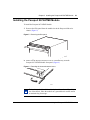
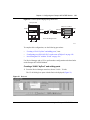
Installing the Passport 8672ATME Module
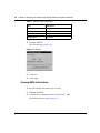
To install the Passport 8672ATME Module:
1
Remove the filler panel from the module slot in the Passport 8600 series
chassis (Figure 5).
Figure 5 Removing the filler panel
9058FB
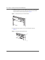
2
Make sure the inserter/extractor levers are extended away from the
Passport 8672ATME Module front panel (Figure 6).
Figure 6 Extending the inserter/extractor levers
.
9059FA
Note: Always handle an I/O module by the sides and carefully slide it
out of the chassis. Place the module on a grounded work surface and in
an antistatic bag for storage.
Using the Passport 8672ATME Module
40
Chapter 3 Installing the Passport 8672ATME Module
3
Handling the Passport 8672ATME Module by the sides only, carefully align it
with the card guides in the chassis. Slide the module into the slot until the
module connectors touch the chassis backplane (Figure 7).
Figure 7 Inserting the Passport 8672ATME Module
MDA 1
MDA 2
8672 ATM
Online
10036FA
4
Rotate the inserter/extractor levers to seat the backplane connectors
(Figure 8).
Figure 8 Closing the inserter/extractor levers
MDA 1
MDA 2
8672 ATM
Online
10037FA
209195-B
Chapter 3 Installing the Passport 8672ATME Module
5
41
Tighten the retaining screws (Figure 9).
Figure 9 Tightening the retainer screws
MDA 1
MDA 2
8672 ATM
Online
10038FA
You must install at least one MDA on the Passport 8672ATME Module in order to
pass traffic. For instructions on installing MDAs, refer to Installing Media
Dependent Adapters for the Passport 8672ATME Module.
For information on configuring and managing the Passport 8672ATME Module,
refer to Chapter 4, “Managing the Passport 8672ATME Module with Device
Manager,” on page 47, to Chapter 5, “Managing the Passport 8672ATME Module
with the CLI,” on page 75, and to Chapter 6, “Configuring the
Passport 8672ATME Module,” on page 117.
Verifying installation
The Passport 8672ATME Module front panel has an Online LED that indicates
whether or not the module has power applied and is initialized correctly. For
information on online LEDs, see “Online LED” on page 30.
Note: You cannot configure the Passport 8672ATME Module until the
online LED on the module is steadily lit green and you have inserted at
least one MDA.
Using the Passport 8672ATME Module
42
Chapter 3 Installing the Passport 8672ATME Module
Initialization
When the Passport 8672ATME Module is installed into a Passport 8600 series
chassis, ensure that the switch fabric module (either the Passport 8690SF or
Passport 8691SF module) in the same chassis has a PCMCIA card inserted and
that the PCMCIA card contains the p80t3200.dld image, which supports the
Passport 8672ATME Module. For more information about the PCMCIA slot and
Passport 8690SF and Passport 8691SF modules, refer to the installation guide that
came with your switch.
The switch fabric module (Passport 8690SF or Passport 8691SF) retrieves the
image file p80t3200.dld to download to the Passport 8672ATME Module. First,
the switch fabric module searches the host flash memory for the file, then the
PCMCIA card. The switch fabric module downloads the image file to the
Passport 8672ATME Module and identifies which MDAs are installed. The screen
displays following message:
Using image = /slot/p80t3200.dld for ATM card download.
ATM card: Slot 4 MDA [OC-12c MM] [Quad OC-3c MM] Ver=2.2
If the image file is not found in either the flash memory or the PCMCIA, the
system stops and the screen displays an error message such as:
ERROR Task=rcStart Couldn’t find an ATM download image!
Aborting card initialization in Slot=4
or:
ERROR Task=rcStart portPresent:port=X/X, invalid port Type
The Passport 8672ATME Module requests a redownload from the switch fabric
module, and the screen displays the following message:
Redownload requested by ATM card in slot <number>.
If the image download is unsuccessful, the screen displays the following message:
ATM card in slot <number> not ready.
If there are three unsuccessful attempts to download, the screen displays the
message shown in Figure 10.
209195-B
Chapter 3 Installing the Passport 8672ATME Module
43
Figure 10 Unsuccessful download screen output
Copyright (c) 1998-2001 Nortel Networks, Inc.
CPU Slot 6:
PPC 740 Map B
Version:
1.0.0.2/3
Creation Time: Jun 29 2000, 23:24:35
Hardware Time: AUG 09 2000, 14:02:57 UTC
Memory Size:
0x04000000
Start Type:
cold
CENTENNIAL
ATA
/flash/ - Volume is OK
Loaded boot configuration from file /flash/boot.cfg
Press <Return> to stop auto-boot...
/pcmcia/ - Volume is OK
2744752 to 12936388 (12936388)
Starting at 0x10000...
CENTENNIAL
ATA
Passport 8600 System Software Release REL3.1.0.0_B022
Copyright (c) 1996-2000 Nortel Networks, Inc.
Waiting for cpu in slot 5 ... 2 seconds
[08/09/00 14:03:13] System boot
/pcmcia/ - Volume is OK
[08/09/00 14:03:13] Passport System Software Release REL3.1.0.0_B022
[08/09/00 14:03:15] Card inserted: Slot=1 Type=8624FX
[08/09/00 14:03:15] Card inserted: Slot=2 Type=8648TX
[08/09/00 14:03:15] Card inserted: Slot=3 Type=8608SX
[08/09/00 14:03:15] Card inserted: Slot=4 Type=8608AT
[08/09/00 14:03:18] Initializing 8624FX in slot #1 ...
[08/09/00 14:03:19] Initializing 8648TX in slot #2 ...
[08/09/00 14:03:21] Initializing 8608SX in slot #3 ...
[08/09/00 14:03:24] Initializing 8608AT in slot #4 ...
/flash/ - Volume is OK
[08/09/00 14:03:30] ERROR Task=rcStart Couldn’t find an ATM download
image! Aborting card initialization in Slot=4!
[08/09/00 14:03:30] Initialization of card failed for Slot 4 !
[08/09/00 14:03:30] Loading configuration from /flash/config.cfg
[08/09/00 14:03:30] The system is ready
[08/09/00 14:03:30] ERROR Task=rcStart smMsgSend: failed, DataLength
(0)too large
********************************
* Nortel Networks, Inc.
*
* Copyright (c) 1996-2000
*
* All Rights Reserved
*
* Passport 8006
*
* Software Release REL3.1.0.0_B02
********************************
Login: [08/09/00 14:04:15] Sending Cold-Start Trap
Using the Passport 8672ATME Module
44
Chapter 3 Installing the Passport 8672ATME Module
After the image loads onto the Passport 8672ATME Module, it performs a series
of self-diagnostic tests. If the module fails the diagnostics, the screen displays the
following message:
Fatal bring up error on ATM card in slot <number>.
If you see this message, contact a service representative. For information on
contacting service representatives, refer to “How to get help” on page 24.
When the image successfully loads onto the Passport 8672ATME Module, the
screen displays the following message:
ATM card in slot <number> is online.
The switch fabric module (Passport 8690SF or Passport 8691SF) can download
the image to two Passport 8672ATME Modules in the same Passport 8600 series
chassis simultaneously.
Note: If you accidentally delete the image file, reset the card and
redownload the file. For information on how to reset the card, see
“Resetting the module” on page 54.
If you have one MDA installed, you can proceed to configure the
Passport 8672ATME Module.
Note: You must save your configuration (using either the CLI or Device
Manager) to preserve the configuration changes you made to the
Passport 8672ATME Module across reboots.
MDA insertion and configuration
Once you insert an MDA, you must complete some basic configuration tasks for
the Passport 8672ATME Module to begin switching operations as soon as it
completes initialization. For information on installing MDAs, refer to Installing
the Installing Media Dependent Adapters for the Passport 8672ATME Module.
209195-B
Chapter 3 Installing the Passport 8672ATME Module
45
To verify that the Passport 8672ATME Module is ready to receive and transmit
traffic, check the LEDs on the module and the MDA. Once you enable the ports
using the CLI or Device Manager, the online LED on the module lights steady
green, and the module is ready. See “Online LED” on page 30 and “MDA LEDs”
on page 31.
For information on enabling ports, refer to “Editing port parameters” on page 58.
You configure and manage the Passport 8600 series switch operation for your
network using the command line interface (CLI) or SNMP-based network
management software, such as Device Manager. For information on configuring
and managing the Passport 8672ATME Module, refer to Chapter 4, “Managing
the Passport 8672ATME Module with Device Manager,” on page 47, to
Chapter 5, “Managing the Passport 8672ATME Module with the CLI,” on page
75, and to Chapter 6, “Configuring the Passport 8672ATME Module,” on page
117.
Factory default settings for the Passport 8672ATME Module are shown in
Appendix B, “Factory defaults,” on page 155.
Replacing a module
You can hot-swap Passport 8672ATME Modules as long as the module you are
inserting has the same MDAs installed as the module you are replacing. In this
case, the system saves the previous configurations. If you hot-swap the module
with a module that has different MDAs installed, you must reconfigure the
module.
If you are hot-swapping modules, read the following section for information about
how the routing switch recognizes replacement modules and how to avoid
potential problems.
Warning: The Passport 8672ATME Module itself is hot-swappable; the
MDAs necessary to pass traffic on the module are not hot-swappable.
Using the Passport 8672ATME Module
46
Chapter 3 Installing the Passport 8672ATME Module
Starting the system after a module replacement
After you a replace a module on the chassis, you can expect the following results:
•
•
•
In a running system, when you replace an I/O module with a module of the
same type, the system restores the configuration of all the ports.
When you replace a module with one of a different type, the system discards
the configuration of the old ports, and the new ports are added to either the
default VLAN or a null VLAN, depending on the operating mode of the
switch.
When you save the configuration in nonvolatile random access memory
(NVRAM), turn off the switch, replace a module with a different module type,
and turn the system on again, the system discards the configuration of the old
ports, and adds new ports to either the default VLAN or an unassigned
VLAN, depending on the operating mode of the switch.
Starting the system with an empty slot
When you save the configuration in NVRAM, shut down the system, remove a
module, turn on the chassis with that slot empty, and then populate the slot with a
module of the same type as the one previously there, the system is not able to
restore the original configuration.
209195-B
47
Chapter 4
Managing the Passport 8672ATME Module with
Device Manager
Two management tools enable you to manage your Passport 8672ATME Module:
Device Manager and the command line interface (CLI). You can also use the
embedded Web-based management feature to monitor the 8672ATME Module.
This chapter contains information on these topics:
•
•
•
•
“Port numbering,” next
“Device Manager” on page 48
“Configuring and managing ATM” on page 51
“Configuring ATM F5-OAM End-to-End Loopback” on page 70
Refer to Chapter 5, “Managing the Passport 8672ATME Module with the CLI”
for information about managing your Passport 8672ATME Module with the CLI
and monitoring the module with the Web-based management features.
Port numbering
You must install an MDA into the Passport 8672ATME Module in order to have
connectivity. The module contains two slots for MDAs, and you can mix and
match among the following MDAs, which are available in both SMF and MMF:
•
•
1-port OC-12c/STM-4
4-port OC-3c/STM-1
Using the Passport 8672ATME Module
48
Chapter 4 Managing the Passport 8672ATME Module with Device Manager
The management systems identify an interface by its slot number (in the Passport
8600 series chassis) and its port number, using the syntax slot number/port
number (s/p). The Passport 8672ATME Module can contain up to eight ports
when two 4-port MDAs are inserted. Port numbers 1 to 4 are reserved for the
MDA in the left slot regardless of the actual physical number of ports. Port
numbers 5 to 8 apply to the MDA in the right slot regardless of the actual physical
number of ports.
For example, a Passport 8672ATME Module in the third slot of the Passport 8600
series chassis with an OC-12c/STM-4 MDA in the left slot and an OC-3c/STM-1
MDA in the right slot has the following port numbers for management and
configuration:
•
•
•
•
•
3/1: OC-12c
3/5: OC-3c/STM-1, left port
3/6: OC-3c/STM-1, port second from left
3/7: OC-3c/STM-1, port second from right
3/8: OC-3c/STM-1, right port
As another example of port numbering, a Passport 8672ATME Module in the
second slot of the chassis with two OC-12c/STM-4 MDAs installed has the
following port numbers:
•
•
2/1: OC-12c/STM-4, left
2/5: OC-12c/STM-4, right
A Passport 8672ATME Module with two OC-3c/STM-1 MDAs installed has ports
numbered consecutively 1 through 8, from left to right.
Device Manager
Passport Device Manager is an SNMP-based graphical user interface tool
designed to manage single devices. In order to use Device Manager, you must
have network connectivity to a management station running Device Manager on
one of the supported platforms.
209195-B
Chapter 4 Managing the Passport 8672ATME Module with Device Manager
49
For detailed information on all aspects of installing and running Device Manager,
refer to:
•
•
Getting Started with the Passport 8000 Series Switch Management Software
Configuring Switching and Routing Operations for the Passport 8000 Series
Switch Using Device Manager Release 5.x.x
The following sections describe the Device Manager features that are specific to
the Passport 8672ATME Module:
•
•
•
•
•
“Installing Device Manager,” next
“Configuring and managing ATM” on page 51
“Configuring ATM F5-OAM End-to-End Loopback” on page 70
“Displaying statistics using Device Manager” on page 73
“Testing using Device Manager” on page 73
Device Manager access and passwords
For a complete discussion of Passport access levels and passwords, refer to
Configuring Switching and Routing Operations for the Passport 8000 Series
Switch Using Device Manager Release 5.x.x.
Installing Device Manager
To install Device Manager:
1
Download the Device Manager software from the CD.
2
Double-click the icon and follow the instructions on the screen.
When you launch Device Manager, a graphical image of the Passport 8600
chassis with the Passport 8672ATME Module installed is displayed
(Figure 11).
Using the Passport 8672ATME Module
50
Chapter 4 Managing the Passport 8672ATME Module with Device Manager
Figure 11 Passport 8000 series chassis with Passport 8672ATME Module
The ports on the graphical image are color-coded to provide at-a-glance port
status. Table 3 shows the status assigned to each color.
Table 3 Device Manager port color codes
209195-B
Field
Description
Green
Port is operating.
Red
Port has been manually disabled.
Orange
Port has no link.
Light blue
Port is in standby mode.
Dark blue
Port is being tested.
Gray
Port is unmanageable.
Chapter 4 Managing the Passport 8672ATME Module with Device Manager
51
Additionally, many Device Manager windows and dialog boxes contain buttons.
Table 4 describes the function of these buttons.
Table 4 Device Manager buttons
Field
Description
Apply
Applies the changes you entered to fields in a window or dialog box.
Refresh
Refreshes the information in the window. Each time you click
Refresh, new information is polled form the switch and displays.
Close
Closes the window or dialog box and disregards any changes you
made to fields.
Help
Does not function with the Passport 8672ATME Module.
Insert
Inserts or creates a new group, such as traps.
Resize Columns
Resizes column on the screen.
Note: You must always click Apply at the bottom of the tab to
implement any changes you make.
Configuring and managing ATM
This section describes how to use Device Manager to configure and manage ATM,
and includes the following topics:
•
•
•
•
•
•
•
•
•
•
•
“Changing default settings” on page 52
“Resetting the module” on page 54
“Viewing MDA information” on page 56
“Enabling or disabling a port” on page 57
“Editing port parameters” on page 58
“Editing ATM and framing parameters” on page 58
“Editing circuit parameters” on page 60
“Deleting a PVC” on page 63
“Configuring ATM 1483 ELAN parameters” on page 64
“Configuring ATM 1483 ELAN parameters” on page 64
“Deleting an ATM 1483 ELAN” on page 69
Using the Passport 8672ATME Module
52
Chapter 4 Managing the Passport 8672ATME Module with Device Manager
Changing default settings
To change the default settings on the Passport 8000 Series switch or to perform
any configuration tasks in Device Manager:
On the device view, double-click on the port you want to configure.
The Port dialog box opens with the Interface tab displayed (Figure 12).
Figure 12 Interface tab—ATM
209195-B
Chapter 4 Managing the Passport 8672ATME Module with Device Manager
53
Table 5 describes the Interface tab fields.
Table 5 ATM Interface tab fields
Item
Description
Index
Unique value assigned to each interface. The value ranges
between 16 and 255.
Name
Displays the name of this port. To assign or change a name to
the port, highlight the field and enter alphanumeric characters.
Descr
Displays the port type of this interface, which may be:
• OC-3c MMF or SMF
• OC-12c MMF or SMF
The card and port numbers are also shown.
Type
Displays the media type of this interface, which may be:
• rcOc3cAtmSM
• rcOc3cAtmMM
• rcOc12cAtmSM
• rcOc12cAtmMM
PhysAddress
MAC address assigned to a particular interface.
VendorDescr
Vendor description.
AdminStatus
Sets the port to either of the following states:
• up
• down
When a managed system initializes, all interfaces start with
AdminStatus in the down state. As a result of either
management or configuration action, the AdminStatus is
changed to the up state (or remains in the down state).
OperStatus
Displays the current operational state of the interface, either:
• up
• down
If AdminStatus is down, then OperStatus should be down.
If AdminStatus is changed to up, then OperStatus should
change to up if the interface is ready to transmit and receive
network traffic. It should remain in the down state if and only if
there is a fault that prevents it from going to the up state.
LastChange
Displays the value of sysUpTime at the time the interface
entered its current operational state. If the current state was
entered prior to the last reinitialization of the local network
management subsystem, the value is zero.
OperSpeed
Displays the current operating speed of the ATM port. For
OC-3c, the operating speed is 155.52 Mb/s; for OC-12c, it is
622.08 Mb/s.
Using the Passport 8672ATME Module
54
Chapter 4 Managing the Passport 8672ATME Module with Device Manager
Table 5 ATM Interface tab fields (continued)
Item
Description
UnknownMacDiscard
DirectBroadcastEnable
Action
Sets one of the following port-related actions:
• none
• flushMacFdb—flush MAC forwarding table for port
• flushArp—flush ARP table for port
• flushIp—flush IP route table for port
• flushAll—flush all tables for port
• triggerRipUpdate—manually update the RIP table
Result
Displays result from the last system action.
Resetting the module
To reset the module:
1
Highlight the module.
2
From the Device Manager menu bar, choose Edit > Card.
The Card dialog box opens with the Card tab displayed (Figure 13).
209195-B
Chapter 4 Managing the Passport 8672ATME Module with Device Manager
55
Figure 13 Card tab
Table 6 describes the Card tab fields.
Table 6 Card tab fields
Field
Description
FrontType
Card type.
FrontDescription
ATM.
FrontAdminStatus
Administrative status of the card.
FrontOperStatus
Operational status of the card.
FrontSerialNum
Serial number of card.
FrontHWVersion
Hardware version.
FrontPartNumer
Part number.
FrontDateCode
Date code.
FrontDeviations
Deviations.
BackType
Card back type.
BackDescription
Description.
BackSerialNum
Serial Number.
Using the Passport 8672ATME Module
56
Chapter 4 Managing the Passport 8672ATME Module with Device Manager
Table 6 Card tab fields (continued)
Field
Description
BackHWVersion
Hardware version.
BackPartNumer
Part number.
BackDateCode
Date code.
BackDeviations
Deviations.
3
Click the ATM tab.
The ATM tab opens (Figure 14).
Figure 14 ATM tab
4
Click reset.
5
Click Apply.
Viewing MDA information
To view information on the MDA you are using,
1
Highlight the MDA.
2
From the Device Manager menu bar, choose Edit > Mda.
The MDA dialog box opens (Figure 15).
209195-B
Chapter 4 Managing the Passport 8672ATME Module with Device Manager
57
Figure 15 MDA dialog box
Table 7 describes the MDA dialog box fields.
Table 7 MDA dialog box fields
Field
Description
Type
Media type:
• rc<XXXX>Oc3BaseSM.
• rc<XXXX>Oc3BaseMM.
• rc<XXXX>Oc12BaseSM.
• rc<XXXX>Oc12BaseMM.
Description
MDA type:
• Quad OC-3c SM — quad port OC-3c single-mode fiber.
• Quad OC-3c MM — quad port OC-3c multimode fiber.
• OC-12c SM — single port OC-12c single-mode fiber.
• OC-12c MM — single port OC-12c multimode fiber.
Enabling or disabling a port
You can enable or disable a port by two methods. To enable or disable a port
through the Device Manager menu bar:
1
On the device view, highlight a port.
2
From the Device Manager menu bar, choose Edit > Port.
The Port dialog box opens with the Interface tab displayed (Figure 12).
3
In the AdminStatus area, click up to enable the port, or click down to disable
the port.
Using the Passport 8672ATME Module
58
Chapter 4 Managing the Passport 8672ATME Module with Device Manager
4
Click Apply.
To enable or disable a port using a shortcut menu:
1
Right-click on the port.
A shortcut menu opens.
2
Choose Enable or Disable.
Editing port parameters
To view or change the general parameters of the port:
1
On the device view, highlight a port.
2
From the Device Manager menu bar, choose Edit > Port.
The Port dialog box opens with the Interface tab displayed (Figure 12).
Editing ATM and framing parameters
To view or change the ATM and framing parameters of the port:
1
On the device view, highlight a port.
2
From the Device Manager menu bar, choose Edit > Port.
The Port dialog box opens with the Interface tab displayed (Figure 12).
3
Click the ATM tab.
The ATM tab opens (Figure 16).
209195-B
Chapter 4 Managing the Passport 8672ATME Module with Device Manager
59
Figure 16 ATM tab
Table 8 describes the ATM tab fields.
Table 8 ATM tab fields
Item
Description
ifIndex
Interface Index.
MediaType
mmf (multimode fiber) or smf (single-mode fiber)
LineSpeed
For OC-3c, the operating speed is 155.52 Mb/s; for OC-12c, it is
622.08 Mb/s.
NumVpiBits
For OC-3c, 11 bits split between NumVpiBits and NumVciBits.
NumVpiBits cannot exceed 6 bits for OC-3c.
For OC-12c, 13 bits split between NumVpiBits (default is 4) and
NumVciBits (default is 9). NumVpiBits cannot exceed 8 bits for
OC-12c.
NumVciBits
This field is read only. It takes remaining bits from NumVpiBits. For
example, if NumVpiBits is 3 for OC-3c, then NumVciBits is 8.
ScrambleEnable Sets the port to scramble the data by clicking the box.
Using the Passport 8672ATME Module
60
Chapter 4 Managing the Passport 8672ATME Module with Device Manager
Table 8 ATM tab fields (continued)
Item
Description
FramingMode
Sets the framing for the port to:
• sonet (Synchronous Optical Network), the standard format used in
North America.
• sdh (Synchronous Digital Hierarchy), the standard format used
worldwide except in North America.
ClockSource
Sets the clock source for the port to:
• loopTimed, which means clocking is derived from the SONET line.
• freeRunning, which means clocking is derived from the on-board
clock.
Note: If you have two connected Passport 8672ATME Modules, you
must set both to freeRunning or one to freeRunning and one to
loopTimed; do not set both to loopTimed.
LoopBackMode
Sets the loopback mode to:
• off
• internal
• external
MacAddress
MAC address assigned to a particular interface.
Editing circuit parameters
To view and configure ATM PVC parameters:
1
On the device view, highlight a port.
2
From the Device Manager menu bar, choose Edit > Port.
The Port dialog box opens with the Interface tab displayed (Figure 12).
3
Click the ATM PVC tab.
The ATM PVC tab opens (Figure 17).
209195-B
Chapter 4 Managing the Passport 8672ATME Module with Device Manager
61
Figure 17 ATM PVC tab
Table 9 describes the ATM PVC tab fields.
Table 9 ATM PVC tab fields
Item
Description
Vpi
Virtual path identifier.
Vci
Virtual circuit identifier.
PvcId
Internal index ID of the PVC.
Name
Emulated LAN name.
Encapsulation
Encapsulation type: null or llcSnap.
ServiceType
Unspecified bit rate (ubr) or variable bit rate (vbr).
PeakCellRate
Peak cell rate, in cells/second, is the maximum cell rate. The valid
ranges are:
• OC-3—86..182783
• OC-12—86..733490
Note: IP multicast traffic between a Passport module and other
devices may not perform as well as expected unless the peak cell
rate and the sustained cell rate values are updated to their
maximum values; only applicable if the Service Type is vbr.
SustainedCellRate
Sustainable cell rate is an upper bound on the cell rate that is long
relative to that of the PCR; only applicable if the Service Type is vbr.
The valid ranges are:
• OC-3—86..182783
• OC-12—86..733490
MaxBurstSize
Maximum burst size determined by the signaling method; It is coded
as a number of cells that can be transmitted at peak rate and still
conform to the overall algorithm; only applicable if the Service Type
is vbr.
Using the Passport 8672ATME Module
62
Chapter 4 Managing the Passport 8672ATME Module with Device Manager
4
Click Insert.
The Insert ATM PVC dialog box opens (Figure 18).
Figure 18 Insert ATM PVC dialog box
Table 10 describes the Port, Insert ATM PVC dialog box fields.
Table 10 Insert ATM PVC dialog box fields
209195-B
Item
Description
Vpi
Numeric value.
Vci
Numeric value
Note: For <vpi.vci>, 0.0 is not supported.
Name
Alphanumeric characters to assign a name to the PVC.
Encapsulation
Encapsulation type: null or llcSnap.
ServiceType
Unspecified bit rate (ubr) or variable bit rate (vbr).
PeakCellRate
Numeric value, within the range 86...733490; only applicable if
the Service Type is vbr.
SustainedCellRate
Numeric value, within the range 86...733490; only applicable if
the Service Type is vbr.
MaxBurstSize
Numeric value, within the range 2...255; only applicable if the
Service Type is vbr.
Chapter 4 Managing the Passport 8672ATME Module with Device Manager
5
In the Vpi field, type the VPI-bit size.
6
In the Vci field, type the VCI-bit size.
63
Note: For <vpi.vci>, 0.0 is not supported.
7
In the Name field, type the name of the ATM PVC.
8
In the Encapsulation field, select the encapsulation method (null or IIcSnap).
9
In the Service Type field, select the service type (ubr or vbr).
10 If you select vbr in the Service Type field:
a
In the PeakCellRate field, enter the PCR (an integer between 86 and
733490).
b
In the SustainedCellRate field, enter the SCR (an integer between 86 and
733490).
c
In the MaxBurstSize, type the maximum burst size (an integer between 2
and 255).
11 Click Insert.
The Insert ATM PVC dialog box closes.
12 Click Close.
Deleting a PVC
To delete a PVC:
1
On the device view, highlight a port.
2
From the Device Manager menu bar, choose Edit > Port.
The Port dialog box opens with the Interface tab displayed (Figure 12).
3
Click the ATM PVC tab.
4
The ATM PVC tab opens.
5
Click a PvcId entry in the table for the PVC you want to delete.
Using the Passport 8672ATME Module
64
Chapter 4 Managing the Passport 8672ATME Module with Device Manager
Figure 19 ATM PVC tab with a PVC selected
6
Click Delete.
The PVC is deleted.
Configuring ATM 1483 ELAN parameters
To view and configure ATM 1483 ELAN parameters for the port:
1
On the device view, highlight a port.
2
From the Device Manager menu bar, choose Edit > Port.
The Port dialog box opens with the Interface tab displayed (Figure 12).
3
Click the ATM 1483 ELAN tab.
The ATM 1483 ELAN tab opens (Figure 20).
Figure 20 ATM 1483 ELAN tab
209195-B
Chapter 4 Managing the Passport 8672ATME Module with Device Manager
65
Table 11 describes the ATM 1483 ELAN tab fields.
Table 11 ATM 1483 ELAN tab fields
Field
Description
VlanId
VLAN to which the ELAN belongs.
ElanId
Internal ID of the ELAN.
NumPvcIds
Number of PVCs pairs used in the ELAN.
PvcIds
List of PVC IDs, minimum of 1 required.
ConnectType
Type of connection: bridged, IP or IPX.
VlanMacAddress
MAC address assigned to this VLAN: used in IP and IPX
routed circuits when there is no appropriate destination
MAC to use.
DummyMacAddress
Dummy MAC address assigned to this VLAN: used in IP
and IPX routed circuits when there is no appropriate source
MAC to use.
LocalIpAddress
Local IP address for connection type IP.
RemoteIpAddress
Remote IP address for connection type IP.
InArpSendEnable
Enables ARP sending on the ELAN for connection type IP.
InArpSendInterval
Interval of ARP sending for connection type IP.
IpxVlanEncapMethod
One of the following:
• llc
• snap
• ether-ii
• raw
IpxNetworkNum
Network number; IPX only.
StgId
Spanning tree group ID. Only for bridge connection type.
rcStgTaggedBpduVlanId
VLAN ID used for tagging BPDUs.
4
Click Insert.
The Insert ATM 1483 ELAN dialog box opens (Figure 21).
Using the Passport 8672ATME Module
66
Chapter 4 Managing the Passport 8672ATME Module with Device Manager
Figure 21 Port, Insert ATM 1483 ELAN dialog box
Table 12 describes the Insert ATM 1483 ELAN dialog box fields.
Table 12 Port, Insert ATM 1483 ELAN dialog box fields
209195-B
Item
Description
VlanId
VLAN ID.
PvcIds
Value for Pvc IDs.
ConnectType
Types of connection: bridged, IP or IPX.
LocalIpAddress
IP address of the device.
RemoteIpAddress
IP address of the device to which you are connecting.
InArpSendEnable
Enables ARP sending on the ELAN for connection type IP.
InArpSendInterval
Interval of ARP sending for connection type IP.
IpxVlanEncapMethod
IPX encapsulation protocol: llc, snap, ether-ii, or raw.
IpxNetworkNum
Network number; numeric value, within the range
0...2147483647.
Chapter 4 Managing the Passport 8672ATME Module with Device Manager
5
In the VlanId field, type the VLAN ID.
6
In the PvcIds field, type the PVC ID.
67
Note: For <vpi.vci>, 0.0 is not supported.
7
In the ConnectType field, select the type of routing protocol: bridged, ip, or
ipx.
8
If bridged is selected in the ConnectType field, click Insert.
9
If Ip is selected in the ConnectType field, complete the following fields:
a
In the LocalIpAddress field, type the IP address of the device.
b
In the RemoteIpAddress field, type the IP address of the device that you
are connecting to in the 1483 ELAN.
c
Select the InArpSendEnable option to enable Arp packets.
d
In the InArpSendInterval field, type the time interval between 0 and 60
seconds.
e
Click Insert.
Figure 22 shows the relevant fields for IP routing.
Using the Passport 8672ATME Module
68
Chapter 4 Managing the Passport 8672ATME Module with Device Manager
Figure 22 Insert ATM 1483 ELAN dialog box for IP routing
10 If Ipx is selected in the ConnectType field, complete the following fields:
a
In the IpxVlanEncapMethod, select the encapsulation method (llc, snap,
ether-ii, or raw).
b
In the IpxNetworkNum field, enter the network number (an integer
between 0 and 2147483647.
c
Click Insert.
Figure 23 shows the relevant fields for IPX routing.
209195-B
Chapter 4 Managing the Passport 8672ATME Module with Device Manager
69
Figure 23 Insert ATM 1483 ELAN dialog box for IPX routing
Deleting an ATM 1483 ELAN
To delete an ATM 1483 ELAN:
1
On the device view, highlight a port.
2
From the Device Manager menu bar, choose Edit > Port.
The Port dialog box opens with the Interface tab displayed (Figure 12).
3
Click the ATM 1483 ELAN tab.
The ATM 1483 ELAN tab opens (Figure 24).
Figure 24 ATM 1483 ELAN tab with ElanId selected
4
Select the ATM 1483 ELAN to be deleted by clicking the ElanId entry in the
table.
Figure 24 shows a highlighted ElanId entry.
Using the Passport 8672ATME Module
70
Chapter 4 Managing the Passport 8672ATME Module with Device Manager
5
Click Delete.
The ATM 1483 ELAN is deleted.
Configuring ATM F5-OAM End-to-End Loopback
A Passport 8672ATME Module, by default, replies to ATM F5-OAM Loopback
requests received. However, the transmission of F5-OAM Loopback requests and
the processing of F5-OAM Loopback replies received require enabling this
feature on a PVC by PVC basis. It is recommended that you enable ATM
F5-OAM on all the PVCs configured on the PP8672 ATM port, in order for upper
layer protocols such as MLT and OSPF to be immediately aware of the port down
status or link failures.
You can configure the ATM F5-OAM End-to-End Loopback parameters with
Device Manager or the CLI. For information on how to configure this feature with
the CLI, see “Managing the Passport 8672ATME Module with the CLI” on
page 75.
This section contains the following topics:
•
•
“Enabling and defining ATM F5-OAM parameters,” next
“Displaying F5 Loopback statistics” on page 72
Enabling and defining ATM F5-OAM parameters
To enable and define the parameters of the ATM F5-OAM Loopback feature in
Device Manager:
1
From the Device Manager menu bar choose Edit > ATM.
The ATM dialog box opens with the ATM PVC tab displayed (Figure 25).
209195-B
Chapter 4 Managing the Passport 8672ATME Module with Device Manager
71
Figure 25 ATM PVC dialog box—ATM PVC tab
2
Highlight a PVC.
3
Click F5 Loopback.
The F5 Loopback dialog box opens with the F5 Loopback tab displayed
(Figure 26).
Figure 26 F5 Loopback dialog box
Table 13 describes the F5 Loopback tab fields.
Table 13 F5 Loopback tab field descriptions
Field
Description
LbMgmtEnable
Click to enable or disable the F5-OAM Loopback feature.
LbSendFrequency
Enter the number of seconds (1-255) between transmitting OAM
loopback requests. The default value is 5 seconds.
LbRetryFrequency
Enter the number of seconds (1-255) between attempting to
resend the transmission. The default value is 1 second.
Using the Passport 8672ATME Module
72
Chapter 4 Managing the Passport 8672ATME Module with Device Manager
Table 13 F5 Loopback tab field descriptions (continued)
Field
Description
LbUpCount
Enter the number of consecutive end-to-end F5-OAM loopback
cell responses (1-255) that must be received in order to change a
PVC connection state to up. The default value is 3 responses.
LbDownCount
Enter the number of consecutive end-to-end F5-OAM loopback
cell responses (1-255) to be not received in order to change a
PVC state to down. The default value is 5 responses (not
received).
TrapEnable
Click to enable or disable OAM traps. When enabled, a trap is
sent to the management station when rc2kAtmPvcOamVcStatus
is going up or down.
Displaying F5 Loopback statistics
To display F5 Loopback statistics:
1
From the Device Manager menu bar choose Edit > ATM.
The ATM dialog box opens with the ATM PVC tab displayed (Figure 18).
2
Highlight a PVC.
3
Click F5 Loopback.
The F5 Loopback dialog box opens with the F5 Loopback tab displayed
(Figure 26).
4
Click the F5 Loopback Stats tab.
The F5 Loopback Stats tab is displayed (Figure 27).
Figure 27 F5 Loopback Stats tab
209195-B
Chapter 4 Managing the Passport 8672ATME Module with Device Manager
73
Table 14 describes the fields in the F5 Loopback Stats tab.
Table 14 F5 Loopback Stats tab fields
Field
Description
VcStatus
This field indicates the status of the PVC link.
• notManaged—VC is not being managed by OAM
• Down Verify—An OAM loopback failed. End-to-end F5-OAM
loopback cells are sent at the specified retry frequency to verify
that the VC is down. After down-count unsuccessful retries,
the VC goes to the down state (see LbDownCount in Table 13).
• Down—VC has not received responses to end-to-end F5-OAM
loopback cells.
• Up Verify—An OAM loopback was successful. End-to-end
F5-OAM loopback cells are sent at the specified retry
frequency to verify the VC is really up. After up-count
successive and successful loopback retries, the VC goes to the
Up state (see LbUpCount in Table 13).
• Up—End-to-end loopbacks are successful.
LbRequestSent
Number of OAM loopback requests sent.
LbReplyReceive
Number of OAM loopback replies sent.
LbReplySent
Number of OAM loopback replies received.
Displaying statistics using Device Manager
Statistics are not supported in Device Manager in this release. See the “show ports
stats atmport command” on page 94 for information on statistics in the CLI.
Testing using Device Manager
Testing is not supported in this release.
Using the Passport 8672ATME Module
74
Chapter 4 Managing the Passport 8672ATME Module with Device Manager
209195-B
75
Chapter 5
Managing the Passport 8672ATME Module
with the CLI
You can manage your Passport 8672ATME Module through the command line
interface (CLI). You can also use the embedded Web-based management feature
to monitor the 8672ATME Module.
Refer to Chapter 4, “Managing the Passport 8672ATME Module with Device
Manager” for information about port numbering and managing your
Passport 8672ATME Module through Device Manager.
This chapter contains the following topics:
•
•
•
•
•
•
•
“Configuration commands,” next
“Module commands” on page 76
“1483 ELAN statistics” on page 77
“Port commands” on page 79
“Show commands” on page 85
“Configuring ATM F5-OAM End-to-End Loopback” on page 111
“Displaying packet loss counters” on page 116
Using the Passport 8672ATME Module
76
Chapter 5 Managing the Passport 8672ATME Module with the CLI
Configuration commands
This section describes the CLI configuration commands available with the
Passport 8672ATME Module. There are three types of configuration commands:
•
•
•
“Module commands,” next
“1483 ELAN statistics” on page 77
“Port commands” on page 79
Note: If you replace one card with another type of card, Nortel
Networks recommends that you go to the root level of the CLI directory
before using any CLI commands.
Module commands
The module commands allow you to:
•
•
•
Reset the module
View ELAN statistics
Display the image filename for the Passport 8672ATME Module.
The syntax is:
config atmcard <atmslot number>
The required variable <atmslot number> is the slot number of the module in
the Passport 8600 chassis. Table 15 describes the parameters and variables for the
config atmcard command.
209195-B
Chapter 5 Managing the Passport 8672ATME Module with the CLI
77
Table 15 config atmcard command parameters and variables
Parameters and variables
Description
card-reset
Resets the card.
elan-stats
<enable|disable>
Enables collection of ELAN statistics.
info
Displays the image filename for the module.
1483 ELAN statistics
The 1483 ELAN statistics commands allow you to collect ELAN statistics for an
ATM port. The commands are:
•
•
•
config atmcard <slot_number> elan-stats <enable|disable>
clear atm elan-stats <vlan_id>
show atm elan-stats <vlan_id>
config atmcard elan-stats
The collection of ELAN statistics is disabled by default to avoid slowing data
forwarding performance. ELAN statistics should be disabled after collection.
Enabling or disabling the collection of ELAN statistics does not clear the ELAN
statistics counters. This allows the ELAN statistics to be reviewed after the feature
is disabled.
clear atm elan-stats <vlan id>
This command allows you to clear statistics for a particular VLAN ID.
The syntax is:
clear atm elan-stats <vlan_id>
Using the Passport 8672ATME Module
78
Chapter 5 Managing the Passport 8672ATME Module with the CLI
show atm elan-stats <vlan id>
Use this command to display the ELAN statistics for a particular VLAN ID. If the
collection of ELAN statistics is disabled, a message is printed before the ELAN
statistics.
Figure 29 shows sample output from the show atm elan-stats <vlan_id>
command.
Figure 28 show atm elan-stats command output
Passport-8610:5# show atm elan-stats 7
=====================================================================
ATM ELAN STATISTICS
=====================================================================
InOctets:
3208404820
InErrors:
0
InDiscards:
0
OutOctets:
3208281916 OutErrors:
0 OutDiscards:
0
InUcastPkts:
130202
InMcastPkts:
395
InBCastPkts:
59134772
OutUcastPkts:
129406 OutMcastPkts:
391 OutBCastPkts:
59133296
Table 16 describes the information fields for the show atm elan-stats
command.
Table 16 Information fields for the show atm elan-stats command
209195-B
Field
Description
InOctets
Octets received from the ATM interface. This includes the
“InDiscards" PDUs.
OutOctets
Octets transmitted out of the ATM interface.
NOTE: For a Bridge ELAN Type with multiple PVCs, there
will be multiple packets transmitted for a multicast packet,
or for a unicast packet that is not in the CAM. Thus, the
OutOctets may not correlate to the OutUcastPkts +
OutMcastPkts + OutBcastPkts.
InErrors
AAL5 CPCS PDUs received with errors from the ATM
interface. These errors include CRC-32 errors, SAR
time-out errors, and oversized SDU errors.
OutErrors
Number of AAL5 CPCS PDUs that could not be transmitted
due to error.
Chapter 5 Managing the Passport 8672ATME Module with the CLI
79
Table 16 Information fields for the show atm elan-stats command (continued)
Field
Description
InDiscards
Number of received AAL5 CPCS PDUs discarded.
OutDiscards
Ethernet packets discarded.
InUcastPkts
Number of unicast packets received on the ELAN.
OutUcastPkts
Number of unicast packets transmitted on the ELAN.
InMcastPkts
Number of Multicast packets received on the ELAN.
OutMcastPkts
Number of Multicast packets transmitted on the ELAN.
InBcastPkts
Number of broadcast packets received on the ELAN.
OutBcastPkts
Number of broadcast packets transmitted on the ELAN.
clear atm elan-stats
Use this command to clear the ELAN statistics for a particular VLAN ID. The
syntax is:
clear atm elan-stats <vlan_id>
Port commands
The port commands allow you to perform general configuration on the
Passport 8672ATME Module. The port config commands are:
•
•
•
•
config atm <ports>
config atm <ports> pvc
config atm <ports> pvc 1483 {bridged|ip|ipx}
config atm <ports> info
Using the Passport 8672ATME Module
80
Chapter 5 Managing the Passport 8672ATME Module with the CLI
config atm command
Table 17 describes the parameters and variables for the config atm <ports>
command.
Table 17 config atm command parameters and variables
Parameters and variables
Description
action <action choice>
Flushes a MAC, ARP, or IP table or triggers a RIP update. Choices are:
• none
• flushMacFdb
• flushArp
• flushIp
• flushAll
• triggerRipUpdate
number-vpi-bits <number-vpi-bits> •
•
•
Sets the number of bits used to represent VPI. Enter integer from 0
to 8.
For OC-3c, 11 bits split between NumVpiBits and NumVciBits.
NumVpiBits cannot exceed 6 bits for OC-3c.
For OC-12c, 13 bits split between NumVpiBits (default is 4) and
NumVciBits (default is 9). NumVpiBits cannot exceed 8 bits for
OC-12c.
scrambling <enable | disable>
Enables or disables scrambling.
framing-mode <sonet | sdh>
Sets the framing to:
• sonet (Synchronous Optical Network), the standard format used in
North America.
• sdh ( Synchronous Digital Hierarchy), the standard format used
worldwide except in North America.
clock-source <loop-timed |
free-running>
Sets the transmit clock source to:
• loop-timed, which means clocking is derived from line.
• free-running, which means clocking is derived from on-board clock.
Note that if you have two connected Passport 8672ATME Modules,
you must set both to free-running or one to loop-timed and one to
free-running; do not set both to loop-timed.
loop-back-mode <off | internal |
remote>
Sets the loopback mode to:
• off
• internal
• external
209195-B
Chapter 5 Managing the Passport 8672ATME Module with the CLI
81
Table 17 config atm command parameters and variables (continued)
Parameters and variables
Description
state <enable | disable>
Sets the state of the port to enabled or disabled.
info
Shows the last saved port settings and the next-level CLI commands.
Note that this does not show the current settings, but the last saved
settings.
config atm pvc command
Table 18 describes the parameters and variables for the config atm pvc
command.
Table 18 config atm pvc command parameters and variables
Parameters and variables
Description
create < vpi.vci> [name <value>]
[enc <value>] [serv <value>] [pcr
<value>] [scr <value>] [mbs
<value>]
Creates a PVC. The required parameters are:
• vpi is the circuit VPI. Enter a numeric value, within the range.
• vci is the circuit VCI. Enter a numeric value, within the range.
For OC-3c, 11 bits split between Vpi and Vci. Vpi bits cannot
exceed 6 bits for OC-3c.
For OC-12c, 13 bits split between Vpi (default is 4) and Vci (default
is 9). Vpi bits cannot exceed 8 bits for OC-12c.
Note: For <vpi.vci>, 0.0 is not supported.
The optional parameters are:
• name is the display string. Enter up to 256 alphanumeric characters
to name PVC.
• enc is the 1483 encapsulation method, either null or llc-snap.
• serv is the bit rate, either ubr or vbr.
• pcr, with VBR only, is the peak cell rate. The valid ranges are:
OC-3—86..182783
OC-12—86..733490
• scr, with VBR only, is the sustained cell rate. The valid ranges are:
OC-3—86..182783
OC-12—86..733490
• mbs, with VBR only, is the maximum burst size. Enter an integer
from 2 to 255.
Note that no VLANs or ELANs are bound to this PVC until you add
VLAN membership using the config atm <ports> pvc 1483 commands.
Using the Passport 8672ATME Module
82
Chapter 5 Managing the Passport 8672ATME Module with the CLI
Table 18 config atm pvc command parameters and variables (continued)
delete <vpi.vci>
Deletes the specified PVC. Note that this command will fail if the PVC is
still being used by RFC 1483 traffic.
info [<ports>]
Displays PVC information.
config atm pvc 1483 command
Use the config atm pvc 1483 commands to configure 1483 parameters on
the Passport 8672ATME Module. The syntax is:
•
•
•
config atm <ports> pvc 1483 bridged
config atm <ports> pvc 1483 ip
config atm <ports> pvc 1483 ipx
Table 19 describes the parameters and variables for the config atm <ports>
pvc 1483 command.
Table 19 config atm pvc 1483 bridged command parameters and variables
Parameters and variables
Description
add <vid> <vpi.vci> [,<vpi.vci>]...
Adds a number of PVCs to the specified 1483 ELAN. The required
parameters are:
• vid means VLAN ID number.
• vpi.vci means circuit VPI number and the circuit VCI numbers,
respectively; they are separated by a period.
Note: This command fails if the specified VIDs or VPI/VCI pairs belong
to another ELAN or already exist on this ELAN.
create <vid> <vpi.vci>
[,<vpi.vci>]...
Creates a 1483 ELAN consisting of the specified PVCs. The required
parameters are:
• vid means VLAN ID number.
• vpi.vci means circuit VPI number and the circuit VCI numbers,
respectively; they are separated by a period.
Note: This command fails if the specified VIDs or VPI/VCI pairs belong
to another ELAN or already exist on this ELAN.
delete <vid>
Deletes the specified ELAN.
209195-B
Chapter 5 Managing the Passport 8672ATME Module with the CLI
83
Table 19 config atm pvc 1483 bridged command parameters and variables (continued)
remove <vid> <vpi.vci>
[,<vpi.vci>]...
Removes a number of PVCs from the specified 1483 ELAN. The
required parameters are:
• vid means VLAN ID number.
• vpi.vci means circuit VPI number and the circuit VCI numbers,
respectively; they are separated by a period.
Note that this command fails if the PVCs are not present.
info
Displays information on 1483 ELANs.
Table 20 describes the parameters and variables for the config atm pvc
1483 ip command.
Table 20 config atm pvc 1483 ip command parameters and variables
Parameters and variables
Description
create <vid> <vpi.vci> <remoteip> Creates a routed 1483 IP circuit on the specified VLAN to the
specified remote router interface. The optional parameters are:
• vid means VLAN ID number.
• vpi.vci means circuit VPI number and the circuit VCI numbers,
respectively; they are separated by a period.
• remoteip is the IP address of the remote router interface.
Note that the VLAN ID can exist only on this port.
delete <vid>
Deletes the routed 1483 IP circuit on the specified VLAN.
info
Displays information on routed 1483 IP circuits.
Table 21 describes the parameters and variables for the config atm pvc
1483 ipx command.
Using the Passport 8672ATME Module
84
Chapter 5 Managing the Passport 8672ATME Module with the CLI
Table 21 config atm pvc 1483 ipx command parameters and variables
Parameters and variables
Description
create <vid> <vpi.vci> <ipx>
Creates a routed 1483 IPX circuit on the specified VLAN to the
specified remote router interface. The optional parameters are:
• vid means VLAN ID number.
• vpi.vci means circuit VPI number and the circuit VCI numbers,
respectively; they are separated by a period.
• ipx is the IPX Network number of the remote router interface. If this
number is not given, the first IPX Network number configured for
the specified VLAN is used.
Note that the VLAN ID must be previously configured for IPX on this
port.
No ARP functionality is available on this IPX segment.
delete <vid>
Deletes the routed 1483 IPX circuit on the specified VLAN.
info
Displays information on routed 1483 IPX circuits.
config atm info command
Figure 29 shows a sample of the output resulting from executing the config atm
info command.
Figure 29 Sample output for the config atm info command
number-vpi-bits : 4
scrambling
framing-mode
clock-source
loop-back-mode
state
209195-B
:
:
:
:
:
Enable
SONET
Free Running
off
up
Chapter 5 Managing the Passport 8672ATME Module with the CLI
85
Show commands
This section discusses the CLI show commands available with the
Passport 8672ATME Module. These commands allow you to view information
about the module:
show
show
show
show
show
show
show
show
show
show
show
show
show
show
show
show
show
ports
ports
ports
ports
ports
ports
ports
ports
ports
ports
ports
ports
ports
ports
ports
ports
ports
info atm all [<ports>]
info atm fdb
info atm ports [<ports>]
info atm pvc [<ports>]
info atm 1483 [<ports>]
stats atmport [<ports>]
stats atm felinecurrent [<ports>]
stats atm felineinterval <intervalid> [<ports>]
stats atm fepathcurrent [<ports>]
stats atm fepathinterval <intervalid> [<ports>]
stats atm linecurrent [<ports>]
stats atm lineinterval <intervalid> [<ports>]
stats atm pathcurrent [<ports>]
stats atm pathinterval <intervalid> [<ports>]
stats atm sectioncurrent [<ports>]
stats atm sectioninterval <intervalid> [<ports>]
stats atm sonetmediumtbl [<ports>]
Refer to Reference for the Passport 8000 Series Command Line Interface
Switching Operations, and Reference for the Passport 8000 Series Command Line
Interface Routing Operations for a complete list of CLI show commands.
show ports info atm all command
This command displays information (Figure 31) about the configuration for the
specified port or for all ports. The command uses the syntax:
show ports info atm all [<ports>]
Using the Passport 8672ATME Module
86
Chapter 5 Managing the Passport 8672ATME Module with the CLI
Figure 30 show ports info atm all command output
Passport-8610:5/show/ports/info/atm# all
=======================================================
ATM Port Configuration
======================================================
PORT
MDA
SCRAMBLE FRAMING MAX-BITS CLOCK LOOPBACK ADMIN
NUM
DESCRIPION
ENABLE
MODE
VPI VCI SOURCE
MODE STATE STATUS
--------------------------------------------------------------------3/1
OC-12c MM
enable SONET
4
9
free
off
up up
3/5
Quad OC-3c MM enable SONET
2
9
free
off
up up
3/6
Quad OC-3c MM enable SONET
2
9
free
off
up down
3/7
Quad OC-3c MM enable SONET
4
7
free
off
up down
=====================================================================
ATM PVC
=====================================================================
PORT
PVC
SERVICE
NUM
VPI.VCI
ENCAPS
TYPE
--------------------------------------------------------------------3/1
0.100
llc-snap UBR
3/1
3.200
llc-snap UBR
3/6
0.33
llc-snap UBR
3/6
3.90
llc-snap UBR
=====================================================================
1483 Bridged
=====================================================================
PORT VLAN
PVC
NUM
ID
LIST
-------------------------------------------------------------------3/1
6
0.100
3/8
4
3.40,4.50
=====================================================================
1483 IP
=====================================================================
PORT VLAN
PVC
VLAN
LOCAL
REMOTE
NUM
ID
VPI.VCI
MAC ADDRESS
IP ADDRESS
IP ADDRESS
--------------------------------------------------------------------3/6 7
0.100
00:e0:7b:7b:52:01 10.10.80.239
10.10.80.230
====================================================================
1483 IPX
=====================================================================
PORT VLAN
PVC
VLAN
IPX NETWORK IPX
NUM
ID
VPI.VCI
MAC ADDRESS
NUMBER
ENCAP
--------------------------------------------------------------------3/5
17
0.100
00:e0:7b:7b:52:03 10-11Xethernet-ii
Passport-8610:5/show/ports/info/atm# all
209195-B
Chapter 5 Managing the Passport 8672ATME Module with the CLI
87
Table 22 describes the information fields for the show ports info atm
all command.
Table 22 Information fields for the show ports info atm all command
Field
Description
PORT NUM
Port number.
MDA DESCRIPTION
This field describes the MDA:
• Quad OC-3c SM — quad port OC-3c single-mode fiber
• Quad OC-3c MM — quad port OC-3c multimode fiber
• OC-12c SM — single port OC-12c single-mode fiber
• OC-12c MM — single port OC-12c multimode fiber
SCRAMBLE ENABLE
Parameter that enables/disables the scrambling option.
FRAMING MODE
Indicates the framing for the port, either:
• sonet (Synchronous Optical Network), the standard
format used in North America.
• sdh (Synchronous Digital Hierarchy), the standard
format used worldwide except in North America.
MAX-BITS VPI
For OC-3c, 11 bits split between NumVpiBits and
NumVciBits. NumVpiBits cannot exceed 6 bits for OC-3c.
For OC-12c, 13 bits split between NumVpiBits (default is 4)
and NumVciBits (default is 9). NumVpiBits cannot exceed 8
bits for OC-12c.
MAX-BITS VCI
This field is read only. It takes remaining bits from
NumVpiBits. For example, if NumVpiBits is 3 for OC-3c,
then NumVciBits is 8.
CLOCK SOURCE
Indicates whether the Clock Source is either:
• line
• internal
LOOPBACK MODE
Indicates the loopback mode::
• off
• internal
• external
ADMIN STATE
Indicates the Admin State of the port, either:
• up
• down
STATUS
Indicates the status of the port, either:
• up
• down
Using the Passport 8672ATME Module
88
Chapter 5 Managing the Passport 8672ATME Module with the CLI
Table 22 Information fields for the show ports info atm all command (continued)
Field
Description
PVC VPI.VCI
Permanent virtual circuit and the associated vpi and vci
numeric identifiers.
ENCAPS
Encapsulation methods: either null, or llc-snap.
SERVICE TYPE
Unspecified bit rate (ubr) or variable bit rate (vbr).
VLAN ID
VLAN name to which the ELAN belongs.
PVC LIST
List of permanent virtual circuits.
VLAN MAC ADDRESS
The MAC address assigned to this VLAN (used in IP and
IPX routed circuits when there is no appropriate destination
MAC to use).
LOCAL IP ADDRESS
The local Ip address for connection type IP.
REMOTE IP ADDRESS
The remote Ip address for connection type IP.
IPX NETWORK NUMBER
Network number.
IPX ENCAP
Encapsulation method: llc, snap, ether-ii or raw.
show ports info atm fdb command
This command displays information (Figure 31) about the Forwarding Data Base
(FDB) for the 1483 bridged point to multi-point PVCs. The FDB stores the
information that it learns in the Passport 8672ATME Module.
In a point to multi-point connection, the Passport 8672ATME Module uses the
FDB table to determine which PVC to use in the egress direction. The command
uses the syntax:
show ports info atm fdb
209195-B
Chapter 5 Managing the Passport 8672ATME Module with the CLI
89
Figure 31 show ports info atm fdb command output
Passport-8610:5/show/ports/info/atm# fdb
=============================================================
ATM ON BOARD CAM ENTRY
=============================================================
PORT
VLAN
VLAN
PVC
AGE
NUM
ID
MAC ADDRESS
VPI.VCI
TIME
--------------------------------------------------------------------3/1
2
00.00.00.00.03
0.100
5
Table 23 describes the information fields for the show ports info atm
fdb command.
Table 23 Information fields for the show ports info atm fdb command
Field
Description
PORT NUM
Port number.
VLAN ID
VLAN number.
VLAN MAC ADDRESS
The destination MAC address.
PVC VPI.VCI
Permanent virtual circuit and the associated vpi and vci
numeric identifiers.
AGE TIME
The time that elapsed since the MAC address was last
used.
show ports info atm ports command
This command displays information (Figure 32) about the configuration of ATM
ports. The command uses the syntax:
show ports info atm ports
Using the Passport 8672ATME Module
90
Chapter 5 Managing the Passport 8672ATME Module with the CLI
Figure 32 show ports info atm ports command output
Passport-8610:5/show/ports/info/atm# ports
=======================================================================
ATM Port Configuration
=======================================================================
PORT
MDA
SCRAMBLE FRAMING MAX-BITS CLOCK LOOPBACKADMIN STATUS
NUM
DESCRIPION
ENABLE
MODE
VPI VCI SOURCE
MODE STATE
----------------------------------------------------------------------3/1
OC-12c MM
enable SONET
4
9
free
off
up
up
3/5
Quad OC-3c MM enable SONET
2
9
free
off
up
up
3/6
Quad OC-3c MM enable SONET
2
9
free
off
up
down
3/7
Quad OC-3c MM enable SONET
4
7
free
off
up
up
3/8
Quad OC-3c MM enable SONET
4
7
free
off
up
up
Passport-8610:5/show/ports/info/atm#
Table 24 describes the information fields for the show ports info atm
ports command.
Table 24 Information fields for the show ports info atm ports
command
209195-B
Field
Description
PORT NUM
Port number.
MDA DESCRIPTION
This field describes the MDA:
• Quad OC-3c SM — dual port OC-3c single-mode fiber
• Quad OC-3c MM — dual port OC-3c multimode fiber
• OC-12c SM — single port OC-12c single-mode fiber
• OC-12c MM — single port OC-12c multimode fiber
SCRAMBLE ENABLE
Parameter that enables/disables the scrambling option.
FRAMING MODE
Indicates the framing for the port, either:
• sonet (Synchronous Optical Network), the standard
format used in North America.
• sdh (Synchronous Digital Hierarchy), the standard
format used worldwide except in North America.
MAX-BITS VPI
For OC-3c, 11 bits split between NumVpiBits and
NumVciBits. NumVpiBits cannot exceed 6 bits for OC-3c.
For OC-12c, 13 bits split between NumVpiBits (default is 4)
and NumVciBits (default is 9). NumVpiBits cannot exceed 8
bits for OC-12c.
Chapter 5 Managing the Passport 8672ATME Module with the CLI
91
Table 24 Information fields for the show ports info atm ports
command (continued)
Field
Description
MAX-BITS VCI
This field is read only. It takes remaining bits from
NumVpiBits. For example, if NumVpiBits is 3 for OC-3c,
then NumVciBits is 8.
CLOCK SOURCE
Indicates whether the Clock Source is either:
• line
• internal
LOOPBACK MODE
Indicates the loopback mode:
• off
• internal
• external
ADMIN STATE
Indicates the Admin State of the port, either:
• up
• down
STATUS
Indicates the status of the port, either:
• up
• down
show ports info atm pvc command
This command displays information (Figure 33) about the permanent virtual
circuits (PVCs) for the specified port or for all ports. The command uses the
syntax:
show ports info atm pvc [<ports>]
Using the Passport 8672ATME Module
92
Chapter 5 Managing the Passport 8672ATME Module with the CLI
Figure 33 show ports info atm pvc command output
Passport-8610:5/show/ports/info/atm# pvc
====================================================================
ATM PVC
====================================================================
PORT
PVC
SERVICE
F5
OAM
SEND RETRY
UP
NUM
VPI.VCI
ENCAPS
TYPE
OAM
TRAP
FREQ FREQ
COUNT
-------------------------------------------------------------------3/1
3/1
3/6
3/6
3/8
3/8
3/8
0.100
3.200
0.33
3.90
3.40
4.50
7.100
llc-snap
llc-snap
llc-snap
llc-snap
llc-snap
llc-snap
llc-snap
UBR
UBR
UBR
UBR
UBR
UBR
UBR
disable
enable
disable
enable
enable
disable
disable
disable
disable
disable
disable
enable
disable
disable
5
5
5
10
5
5
5
1
1
1
3
2
1
1
DOWN
COUNT
3
3
3
3
5
3
3
5
5
5
5
5
5
5
Passport-8610:5/show/ports/info/atm#
Table 25 describes the information fields for the show ports info atm
pvc command.
Table 25 Information fields for the show ports info atm pvc command
209195-B
Field
Description
PORT NUM
Port number.
PVC VPI.VCI
Permanent virtual circuit and the associated vpi and vci
numeric identifiers.
ENCAPS
Encapsulation method: null or llc-snap.
SERVICE TYPE
Unspecified bit rate (ubr) or variable bit rate (vbr).
F5 OAM
Status of F5-OAM Loopback feature: enable or disable.
OAM TRAP
Status of the SNMP Trap when the F5-OAM Loopback
changes from the DOWN VERIFY to DOWN state or from
the UP VERIFY to UP state: enable or disable.
SEND FREQ
Transmission rate (in seconds) of F5-OAM Loopback
requests.
RETRY FREQ
Retry-transmission rate (in seconds) of F5-OAM Loopback
requests.
UP COUNT
Number of consecutive F5-OAM Loopback replies that
must be received to change the Loopback State to “up.”
DOWN COUNT
Number of consecutive F5-OAM Loopback replies that
must fail to change the Loopback State to “down.”
Chapter 5 Managing the Passport 8672ATME Module with the CLI
93
show ports info atm 1483 command
This command displays information (Figure 34) about 1483 circuits for the
specified port or for all ports. The command uses the syntax:
show ports info atm 1483 [<ports>]
Figure 34 show ports info atm 1483 command output
Passport-8610:5# show ports info atm 1483 3/8
================================================================
1483 Bridged
================================================================
PORT VLAN
PVC
NUM
ID
LIST
---------------------------------------------------------------================================================================
1483 IP
================================================================
PORT VLAN
PVC
VLAN
LOCAL REMOTE
NUM
ID
VPI.VCI
MAC ADDRESS
IP ADDRESS IP ADDRESS
--------------------------------------------------------------3/8
7
0.100
00:e0:7b:7b:52:01 10.10.80.239 10.10.80.2
================================================================
1483 IPX
================================================================
PORT VLAN
PVC
VLAN
IPX NETWORK IPX
NUM
ID
VPI.VCI
MAC ADDRESS
NUMBER
ENCAP
---------------------------------------------------------------Passport-8610:5#
Table 26 describes the information fields for the show ports info atm
1483 command.
Table 26 Information fields for the show ports info atm 1483
command
Field
Description
PORT NUM
Port number.
VLAN ID
VLAN name to which the ELAN belongs.
PVC LIST
List of permanent virtual circuits.
Using the Passport 8672ATME Module
94
Chapter 5 Managing the Passport 8672ATME Module with the CLI
Table 26 Information fields for the show ports info atm 1483
command (continued)
Field
Description
VLAN MAC ADDRESS
MAC address assigned to this VLAN: used in IP and IPX
routed circuits when there is no appropriate destination
MAC to use.
LOCAL IP ADDRESS
Local IP address for connection type IP.
REMOTE IP ADDRESS
Remote IP address for connection type IP.
IPX NETWORK NUMBER
Network number.
IPX ENCAP
Encapsulation method: llc, snap, ether-ii, or raw.
show ports stats atmport command
This command displays statistics for atm ports (Figure 35). The command uses
the syntax:
show ports stats atmport [<port num>]
209195-B
Chapter 5 Managing the Passport 8672ATME Module with the CLI
95
Figure 35 show ports stats atmport [<port num>] command output
Passport-8606:6/show/ports/stats# atmport
===========================================================================
ATM Port Statistics I
===========================================================================
PORT
IN
OUT
IN CORR
IN UNCORR
NUM
CELLS
CELLS
HCS ERR
HCS ERR
--------------------------------------------------------------------------3/1
0
6744908
0
0
3/2
0
6744901
0
0
3/3
0
6744893
0
0
3/4
0
6744888
0
0
3/5
0
35314189
0
0
===========================================================================
ATM Port Statistics II
===========================================================================
PORT
IN
OUT
IN DROP
OUT DROP UNKNOWN VPI/VCI
IDLE
NUM
PKTS
PKTS
PKTS
PKTS
CELLS
CELLS
--------------------------------------------------------------------------3/1
0
0
0
0
0
6746913
3/2
0
0
0
0
0
6746912
3/3
0
0
0
0
0
6746913
3/4
0
0
0
0
0
8096349
3/5
0
0
0
0
0
42386582
Passport-8606:6/show/ports/stats#
Table 27 describes the information fields for the show ports stats
atmport command.
Table 27 Information fields for the show ports stats atmport
command
Field
Description
PORT NUM
Port number.
IN CELLS
Received cells.
OUT CELLS
Transmitted cells.
IN CORR HCS ERR
Number of received cells in which the HCS was corrected.
IN UNCORR HCS ERR
Number of received cells dropped because the HCS could
not be corrected.
IN PKTS
Number of packets received.
Using the Passport 8672ATME Module
96
Chapter 5 Managing the Passport 8672ATME Module with the CLI
Table 27 Information fields for the show ports stats atmport
command (continued)
Field
Description
OUT PKTS
Number of packets transmitted.
IN DROP PKTS
Number of in-bound packets dropped.
OUT DROP PKTS
Number of out-bound packets dropped.
UNKNOWN VPI/VCI CELLS Number of packets for which the vpi/vci values are
unknown.
IDLE CELLS
Cells that are inactive.
show ports stats atm felinecurrent
This command displays current statistics on the far end line, which is at the
receiving end. The command uses the syntax:
show ports stats atm felinecurrent [<ports>]
Figure 36 shows sample output for the show ports stats atm
felinecurrent command.
209195-B
Chapter 5 Managing the Passport 8672ATME Module with the CLI
97
Figure 36 show ports stats atm felinecurrent command output
Passport-8610:5/show/ports/stats/atm# felinecurrent
======================================================================
ATM Far End Line Current Stats
======================================================================
PORT
ERRORED SECONDS
SEVERELY ERRORED
CODE VIOLATION UNAVAILABLE
NUM
COUNT (ES)
COUNT (SES)
COUNT (CV-L) SECONDS(UAS)
---------------------------------------------------------------------3/1
0
0
0
0
3/5
0
0
0
0
9/1
0
0
0
0
9/2
0
0
0
0
9/3
0
0
0
0
9/4
0
0
0
0
9/5
0
0
0
0
9/6
0
0
0
0
9/7
0
0
0
0
9/8
0
0
0
0
Passport-8610:5/show/ports/stats/atm# felinecurrent
Table 28 describes the information fields for the show ports stats atm
felinecurrent command.
Table 28 Information fields for the show ports stats atm felinecurrent command
Field
Description
PORT NUM
Port number.
ERRORED SECONDS
COUNT (ES)
Errored Second (ES) is a second with one or more Coding
Violations (CV) or one or more incoming defects (for
example, SEF, LOS, AIS, LOP).
SEVERELY ERRORED
COUNT (SES)
Severely Errored Second (SES) is a second with x or more
CVs, or one or more incoming defects.
CODE VIOLATION COUNT
(CV-L)
Coding Violations (CV) are Bit Interleaved Parity (BIP)
errors that are detected in the incoming signal. CV
counters are incremented for each BIP error detected.
UNAVAILABLE SECONDS
Number of seconds that the interface is unavailable.
Using the Passport 8672ATME Module
98
Chapter 5 Managing the Passport 8672ATME Module with the CLI
show ports stats atm felineinterval
This command displays statistics (Figure 37) on the far end line over a 15-minute
interval. You specify which interval, or span of intervals, to display for the
command. The command uses the syntax:
show ports stats atm felineinterval <intervalid> [<ports>]
Figure 37 show ports stats atm felineinterval command output
Passport-8610:5/show/ports/stats/atm# felineinterval 96
======================================================================
ATM Far End Line Interval Stats
======================================================================
PORT
ERRORED SECONDS
SEVERELY ERRORED
CODE VIOLATION UNAVAILABLE
NUM
COUNT (ES)
COUNT (SES)
COUNT (CV-L) SECONDS(UAS)
---------------------------------------------------------------------3/1
0
0
0
0
3/5
0
0
0
0
9/1
0
0
0
0
9/2
0
0
0
0
9/3
0
0
0
0
9/4
0
0
0
0
9/5
0
0
0
0
9/6
0
0
0
0
9/7
0
0
0
0
9/8
0
0
0
0
INTERVAL ID = 96
Passport-8610:5/show/ports/stats/atm#
Table 29 describes the information fields for the show ports stats atm
felineinterval command.
Table 29 Information fields for the show ports stats atm felineinterval
command
209195-B
Field
Description
PORT NUM
Port number.
ERRORED SECONDS
COUNT (ES)
Errored Second (ES) is a second with one or more Coding
Violations (CV) or one or more incoming defects (for
example, SEF, LOS, AIS, LOP).
Chapter 5 Managing the Passport 8672ATME Module with the CLI
99
Table 29 Information fields for the show ports stats atm felineinterval
command (continued)
Field
Description
SEVERELY ERRORED
COUNT (SES)
Severely Errored Second (SES) is a second with x or more
CVs, or one or more incoming defects.
CODE VIOLATION COUNT
(CV-L)
Coding Violations (CV) are Bit Interleaved Parity (BIP)
errors that are detected in the incoming signal. CV
counters are incremented for each BIP error detected.
UNAVAILABLE SECONDS
(UAS)
The number of seconds that the interface is unavailable.
INTERVAL ID
Specified interval.
show ports stats atm fepathcurrent
This command displays current statistics (Figure 38) for the far end path, which is
at the receiving end. The command uses the syntax:
show ports stats atm fepathcurrent [<ports>]
Figure 38 show ports stats atm fepathcurrent command output
Passport-8610:5/show/ports/stats/atm# fepathcurrent
=========================================================================
ATM Far End Path Current Stats
=========================================================================
PORT
ERRORED SECONDS
SEVERELY ERRORED
CODE VIOLATION
UNAVAILABLE
NUM
COUNT (ES)
COUNT (SES)
COUNT (CV-P)
SECONDS(UAS)
------------------------------------------------------------------------3/1
0
0
0
264
3/5
0
0
0
264
9/1
0
0
0
0
9/2
0
0
0
0
9/3
0
0
0
0
9/4
0
0
0
0
9/5
0
0
0
0
9/6
0
0
0
0
9/7
0
0
0
0
9/8
0
0
0
0
Passport-8610:5/show/ports/stats/atm# fepathcurrent
Using the Passport 8672ATME Module
100
Chapter 5 Managing the Passport 8672ATME Module with the CLI
Table 30 describes the information fields for the show ports stats atm
fepathcurrent command.
Table 30 Information fields for the show ports stats atm fepathcurrent command
Field
Description
PORT NUM
Port number.
ERRORED SECONDS
COUNT (ES)
Errored Second (ES) is a second with one or more Coding
Violations (CV) or one or more incoming defects (for
example, SEF, LOS, AIS, LOP).
SEVERELY ERRORED
COUNT (SES)
Severely Errored Second (SES) is a second with x or more
CVs, or one or more incoming defects.
CODE VIOLATION COUNT
(CV-P)
Coding Violations (CV) are Bit Interleaved Parity (BIP)
errors that are detected in the incoming signal. CV
counters are incremented for each BIP error detected.
UNAVAILABLE SECONDS
(UAS)
The number of seconds that the interface is unavailable.
show ports stats atm fepathinterval
This command displays statistics (Figure 39) on the far end path over a 15-minute
interval. You specify the interval or span of intervals to display. The command
uses the syntax:
show ports stats atm fepathinterval <intervalid> [<ports>]
209195-B
Chapter 5 Managing the Passport 8672ATME Module with the CLI
101
Figure 39 show ports stats atm fepathinterval command output
Passport-8610:5/show/ports/stats/atm# fepathinterval 96
=========================================================================
ATM Far End Path Interval Stats
=========================================================================
PORT
ERRORED SECONDS
SEVERELY ERRORED
CODE VIOLATION
UNAVAILABLE
NUM
COUNT (ES)
COUNT (SES)
COUNT (CV-P)
SECONDS(UAS)
-----------------------------------------------------------------------3/1
0
0
0
900
3/5
0
0
0
900
9/1
0
0
0
0
9/2
0
0
0
0
9/3
0
0
0
0
9/4
0
0
0
0
9/5
0
0
0
0
9/6
0
0
0
0
9/7
0
0
0
0
9/8
0
0
0
0
INTERVAL ID = 96
Passport-8610:5/show/ports/stats/atm# fepathinterval 96
Table 31 describes the information fields for the show ports stats atm
fepathinterval command.
Table 31 Information fields for the show ports stats atm fepathinterval command
Field
Description
PORT NUM
Port number.
ERRORED SECONDS
COUNT (ES)
Errored Second (ES) is a second with one or more Coding
Violations (CV) or one or more incoming defects (for
example, SEF, LOS, AIS, LOP).
SEVERELY ERRORED
COUNT (SES)
Severely Errored Second (SES) is a second with x or more
CVs, or one or more incoming defects.
CODE VIOLATION COUNT
(CV-P)
Coding Violations (CV) are Bit Interleaved Parity (BIP)
errors that are detected in the incoming signal. CV
counters are incremented for each BIP error detected.
UNAVAILABLE SECONDS
(UAS)
Number of seconds that the interface is unavailable.
INTERVAL ID
Specified interval.
Using the Passport 8672ATME Module
102
Chapter 5 Managing the Passport 8672ATME Module with the CLI
show ports stats atm linecurrent
This command displays current statistics (Figure 40) for the line. The command
uses the syntax:
show ports stats atm linecurrent [<ports>]
Figure 40 show ports stats atm linecurrent command output
Passport-8610:5/show/ports/stats/atm# linecurrent
=========================================================================
ATM Line Current Stats
========================================================================
PORT ERRORED SECONDS SEVERELY ERRORED CODE VIOLATION UNAVAILABLE
NUM
COUNT (ES)
COUNT (SES)
COUNT (CV-L)
SECONDS (UAS) STATUS
------------------------------------------------------------------------3/1
0
0
0
110
LineAIS
3/5
0
0
0
110
Line AIS
9/1
0
0
0
0
No Defect
9/2
0
0
0
0
No Defect
9/3
0
0
0
0
No Defect
9/4
0
0
0
0
No Defect
9/5
0
0
0
0
No Defect
9/6
0
0
0
0
No Defect
9/7
0
0
0
0
No Defect
9/8
0
0
0
0
No Defect
Passport-8610:5/show/ports/stats/atm# linecurrent
Table 32 describes the information fields for the show ports stats atm
linecurrent command.
Table 32 Information fields for the show ports stats atm linecurrent
command
209195-B
Field
Description
PORT NUM
Port number.
ERRORED SECONDS
COUNT (ES)
Errored Second (ES) is a second with one or more Coding
Violations (CV) or one or more incoming defects (for
example, SEF, LOS, AIS, LOP).
Chapter 5 Managing the Passport 8672ATME Module with the CLI
103
Table 32 Information fields for the show ports stats atm linecurrent
command (continued)
Field
Description
SEVERELY ERRORED
COUNT (SES)
Severely Errored Second (SES) is a second with x or more
CVs, or one or more incoming defects.
CODE VIOLATION COUNT
(CV-P)
Coding Violations (CV) are Bit Interleaved Parity (BIP)
errors that are detected in the incoming signal. CV
counters are incremented for each BIP error detected.
UNAVAILABLE SECONDS
(UAS)
Number of seconds that the interface is unavailable.
STATUS
Status of defects.
show ports stats atm lineinterval
This command displays statistics (Figure 41) for the line over a 15-minute
interval. You can specify any interval or span of intervals. The command uses the
syntax:
show ports stats atm lineinterval <intervalid> [<ports>]
Figure 41 show ports stats atm lineinterval command output
Passport-8610:5/show/ports# stats atm lineinterval 96
===========================================================================
ATM Line Interval Stats
===========================================================================
PORT
ERRORED SECONDS
SEVERELY ERRORED
CODE VIOLATION
UNAVAILABLE
NUM
COUNT (ES)
COUNT (SES)
COUNT (CV-L)
SECONDS (UAS)
--------------------------------------------------------------------------3/1
0
0
0
990
3/5
0
0
0
990
9/1
0
0
0
0
9/2
0
0
0
0
9/3
0
0
0
0
9/4
0
0
0
0
9/5
0
0
0
0
9/6
0
0
0
0
9/7
0
0
0
0
9/8
0
0
0
0
INTERVAL ID = 96
Passport-8610:5/show/ports#
Using the Passport 8672ATME Module
104
Chapter 5 Managing the Passport 8672ATME Module with the CLI
Table 33 describes the information fields for the show ports stats atm
lineinterval command.
Table 33 Information fields for The show ports stats atm lineinterval command
Field
Description
PORT NUM
Port number.
ERRORED SECONDS
COUNT (ES)
Errored Second (ES) is a second with one or more Coding
Violations (CV) or one or more incoming defects (for
example, SEF, LOS, AIS, LOP).
SEVERELY ERRORED
COUNT (SES)
Severely Errored Second (SES) is a second with x or more
CVs, or one or more incoming defects.
CODE VIOLATION COUNT
(CV-P)
Coding Violations (CV) are Bit Interleaved Parity (BIP)
errors that are detected in the incoming signal. CV
counters are incremented for each BIP error detected.
UNAVAILABLE SECONDS
(UAS)
Number of seconds that the interface is unavailable.
show ports stats atm pathcurrent
This command displays current statistics (Figure 42) on the path, on the
transmitting end. The command uses the syntax:
show ports stats atm pathcurrent [<ports>]
209195-B
Chapter 5 Managing the Passport 8672ATME Module with the CLI
105
Figure 42 show ports stats atm pathcurrent command output
Passport-8610:5/show/ports/stats/atm# pathcurrent
=========================================================================
ATM Path Current Stats
=========================================================================
PORT ERRED SECS SEVERELY ERRED CODE VIOLATION UNAVAILABLE
NUM
COUNT (ES) COUNT (SES)
COUNT (CV-P)
SECONDS (UAS) STATUS WIDTH
------------------------------------------------------------------------3/1
0
0
0
160
Path AIS 3
3/5
0
0
0
160
Path AIS 3
9/1
0
0
0
0
No Defect 2
9/2
0
0
0
0
No Defect 2
9/3
0
0
0
0
No Defect 2
9/4
0
0
0
0
No Defect 2
9/5
0
0
0
0
No Defect 2
9/6
0
0
0
0
No Defect 2
9/7
0
0
0
0
No Defect 2
9/8
0
0
0
0
No Defect 2
Passport-8610:5/show/ports/stats/atm#
Table 34 describes the information fields for the show ports stats atm
pathcurrent command.
Table 34 Information fields for the show ports stats atm pathcurrent command
Field
Description
PORT NUM
Port number.
ERRED SECS COUNT (ES) Errored Second (ES) is a second with one or more Coding
Violations (CV) or one or more incoming defects (for
example, SEF, LOS, AIS, LOP).
SEVERELY ERRED COUNT Severely Errored Second (SES) is a second with x or more
(SES)
CVs, or one or more incoming defects.
CODE VIOLATION COUNT
(CV-P)
Coding Violations (CV) are Bit Interleaved Parity (BIP)
errors that are detected in the incoming signal. CV
counters are incremented for each BIP error detected.
UNAVAILABLE SECONDS
(UAS)
Number of seconds that the interface is unavailable.
STATUSWIDTH
Status and number of defects.
Using the Passport 8672ATME Module
106
Chapter 5 Managing the Passport 8672ATME Module with the CLI
show ports stats atm pathinterval
This command displays statistics (Figure 43) on the path for a 15-minute interval.
You specify the interval or span of intervals to display. The command uses the
syntax:
show ports stats atm pathinterval <intervalid> [<ports>]
Figure 43 show ports stats atm pathinterval command output
Passport-8610:5/show/ports/stats/atm# pathinterval 96
=========================================================================
ATM Path Interval Stats
=========================================================================
PORT
ERRORED SECONDS
SEVERELY ERRORED
CODE VIOLATION
UNAVAILABLE
NUM
COUNT (ES)
COUNT (SES)
COUNT (CV-P)
SECONDS(UAS)
------------------------------------------------------------------------3/1
0
0
0
160
3/5
0
0
0
160
9/1
0
0
0
0
9/2
0
0
0
0
9/3
0
0
0
0
9/4
0
0
0
0
9/5
0
0
0
0
9/6
0
0
0
0
9/7
0
0
0
0
9/8
0
0
0
0
INTERVAL ID = 96
Passport-8610:5/show/ports/stats/atm#
Table 35 describes the information fields for the show ports stats atm
pathinterval command.
Table 35 Information fields for the show ports stats atm pathinterval
command
209195-B
Field
Description
PORT NUM
Port number.
ERRORED SECONDS
COUNT (ES)
Errored Second (ES) is a second with one or more Coding
Violations (CV) or one or more incoming defects (for
example, SEF, LOS, AIS, LOP).
Chapter 5 Managing the Passport 8672ATME Module with the CLI
107
Table 35 Information fields for the show ports stats atm pathinterval
command (continued)
Field
Description
SEVERELY ERRORED
COUNT (SES)
Severely Errored Second (SES) is a second with x or more
CVs, or one or more incoming defects.
CODE VIOLATION COUNT
(CV-P)
Coding Violations (CV) are Bit Interleaved Parity (BIP)
errors that are detected in the incoming signal. CV
counters are incremented for each BIP error detected.
UNAVAILABLE SECONDS
(UAS)
Number of seconds that the interface is unavailable.
INTERVAL ID
Specified interval.
show ports stats atm sectioncurrent
This command displays the current statistics (Figure 44) on the section. The
command uses the syntax:
show ports stats atm sectioncurrent [<ports>]
Figure 44 show ports stats atm sectioncurrent command output
Passport-8610:5/show/ports/stats/atm# sectioncurrent
==========================================================================
ATM Section Current Stats
==========================================================================
PORT ERRORED SECONDS SEVERELY ERRORED CODE VIOLATION SEVERELY ERRORED
NUM
COUNT (ES)
COUNT (SES)
COUNT (CV-S)
FRAMES (SEF) STATUS
-------------------------------------------------------------------------3/1
796
796
0
796
LOS
3/5
796
796
0
796
LOS
9/1
0
0
0
0
No Defect
9/2
0
0
0
0
No Defect
9/3
0
0
0
0
No Defect
9/4
0
0
0
0
No Defect
9/5
0
0
0
0
No Defect
9/6
0
0
0
0
No Defect
9/7
0
0
0
0
No Defect
Passport-8610:5/show/ports/stats/atm# sectioncurrent
Using the Passport 8672ATME Module
108
Chapter 5 Managing the Passport 8672ATME Module with the CLI
Table 36 describes the information fields for the show ports stats atm
sectioncurrent command.
Table 36 Information fields for the show ports stats atm sectioncurrent command
Field
Description
PORT NUM
Port number.
ERRORED SECONDS
COUNT (ES)
Errored Second (ES) is a second with one or more Coding
Violations (CV) or one or more incoming defects (for
example, SEF, LOS, AIS, LOP).
SEVERELY ERRORED
COUNT (SES)
Severely Errored Second (SES) is a second with x or more
CVs, or one or more incoming defects.
CODE VIOLATION COUNT
(CV-S)
Coding Violations (CV) are Bit Interleaved Parity (BIP)
errors that are detected in the incoming signal. CV
counters are incremented for each BIP error detected.
SEVERELY ERRORED
FRAMES (SEF)
Number of seconds that the interface is unavailable.
STATUS
Indicates status of defects.
show ports stats atm sectioninterval
This command displays statistics (Figure 45) on the section over a 15-minute
interval. You specify the interval or span of intervals to display. The command
uses the syntax:
show ports stats atm sectioninterval <intervalid> [<ports>]
209195-B
Chapter 5 Managing the Passport 8672ATME Module with the CLI
109
Figure 45 show ports stats atm sectioninterval command output
Passport-8610:5/show/ports/stats/atm# sectioninterval 96
===========================================================================
ATM Section Interval Stats
===========================================================================
PORT
ERRORED SECONDS
SEVERELY ERRORED
CODE VIOLATION SEVERELY ERRORED
NUM
COUNT (ES)
COUNT (SES)
COUNT (CV-S) FRAMES (SEF)
--------------------------------------------------------------------------3/1
900
900
0
900
3/5
900
900
0
900
9/1
0
0
0
0
9/2
0
0
0
0
9/3
0
0
0
0
9/4
0
0
0
0
9/5
0
0
0
0
9/6
0
0
0
0
9/7
0
0
0
0
9/8
0
0
0
0
INTERVAL ID = 96
Passport-8610:5/show/ports/stats/atm# sectioninterval 96
Table 37 describes the information fields for the show ports stats atm
sectioninterval command.
Table 37 Information fields for the show ports stats atm sectioninterval command
Field
Description
PORT NUM
Port number.
ERRORED SECONDS
COUNT (ES)
Errored Second (ES) is a second with one or more Coding
Violations (CV) or one or more incoming defects (for
example, SEF, LOS, AIS, LOP).
SEVERELY ERRORED
COUNT (SES)
Severely Errored Second (SES) is a second with x or more
CVs, or one or more incoming defects.
CODE VIOLATION COUNT
(CV-S)
Coding Violations (CV) are Bit Interleaved Parity (BIP)
errors that are detected in the incoming signal. CV
counters are incremented for each BIP error detected.
SEVERELY ERRORED
FRAMES (SEF)
Severely Errored Framing Second (SEFs) is a second
containing one or more SEF events.
INTERVAL ID
Specified interval.
Using the Passport 8672ATME Module
110
Chapter 5 Managing the Passport 8672ATME Module with the CLI
show ports stats atm sonetmediumtbl
This command displays statistics (Figure 46) on the SONET medium. The
command uses the syntax:
show ports stats atm sonetmediumtbl [<ports>]
Figure 46 show ports stats atm sonetmediumtbl command output
Passport-8610:5/show/ports/stats/atm# sonetmediumtbl
=========================================================================
ATM SONET Medium Table
===========================================================================
PORT
MEDIUM
TIME
VALID
LINE
LINE
CIRCUIT
NUM
TYPE
ELAPSED
INTERVALS
CODING TYPE
ID
--------------------------------------------------------------------------3/1
0
731
96
4
3
53754784
3/5
0
731
96
4
3
53754784
9/1
0
715
96
4
4
53754784
9/2
0
715
96
4
4
53754784
9/3
0
715
96
4
4
53754784
9/4
0
715
96
4
4
53754784
9/5
0
715
96
4
4
53754784
9/6
0
715
96
4
4
53754784
9/7
0
715
96
4
4
53754784
9/8
0
715
96
4
4
53754784
Passport-8610:5/show/ports/stats/atm# sonetmediumtbl
Table 38 describes the information fields for the show ports stats atm
sonetmediumtbl command.
Table 38 Information fields for output of the show ports stats atm
sonetmediumtbl command
209195-B
Field
Description
PORT NUM
Port number.
MEDIUM TYPE
Identifies whether a sonet or sdh signal is used across the
interface.
Chapter 5 Managing the Passport 8672ATME Module with the CLI
111
Table 38 Information fields for output of the show ports stats atm
sonetmediumtbl command (continued)
Field
Description
TIME ELAPSED
Number of seconds, including partial seconds, that have
elapsed since the beginning of the current measurement
period. If the current interval exceeds the maximum value,
the agent will return the maximum value.
VALID INTERVALS
Number of previous 15-minute intervals for which data was
collected.
LINE CODING
Line coding for this interface. The B3ZS and CMI are used
for electrical SONET/SDH signals (STS-1 and STS-3). The
Non-Return to Zero (NZR) and the Return to Zero are used
for optical SONET/SDH signals.
LINE TYPE
Line type for this interface. The line types are Single Mode
fiber or Multi-Mode fiber interfaces.
CIRCUIT ID
Transmission vendor’s circuit identifier, to facilitate
troubleshooting.
Configuring ATM F5-OAM End-to-End Loopback
A Passport 8672ATME Module, by default, replies to ATM F5-OAM Loopback
requests received. However, the transmission of F5-OAM Loopback requests and
the processing of F5-OAM Loopback replies received require enabling this
feature on a PVC by PVC basis. It is recommended that you enable ATM
F5-OAM on all the PVCs configured on the PP8672 ATM port in order for upper
layer protocols such as MLT and OSPF to be immediately aware of the port down
status or link failures.
You can enable and define the parameters of the ATM F5-OAM Loopback feature
and display statistics with Device Manager or the CLI. For information on how to
configure this feature with the Device Manager, see Chapter 4, “Managing the
Passport 8672ATME Module with Device Manager,” on page 47.
The F5-OAM loopback feature uses the following CLI commands:
•
•
•
•
config atm pvc f5-oam command
show ports info atm pvc [slot/port]
show ports info atm f5-oam [slot/port]
clear atm f5-oam [slot/port]
Using the Passport 8672ATME Module
112
Chapter 5 Managing the Passport 8672ATME Module with the CLI
config atm pvc f5-oam command
This CLI command enables/disables and configures the F5-OAM Loopback
feature for a virtual circuit (VC). When this command is used for disabling the
F5-OAM Loopback on a VC, the configuration parameters are ignored. The
command uses the syntax:
config atm <slot/port> pvc f5-oam <vpi.vci> <enable|disable>
[send <value>] [retry <value>] [up <value>] [down <value>]
[trap <enable|disable>]
When this command is used for enabling the F5-OAM Loopback on a VC, the
other parameters configure the F5-OAM Loopback. When the F5-OAM Loopback
on a VC is already enabled, an enable command towards this VC may change its
F5-OAM Loopback configuration but it does not alter its F5-OAM statistics.
When the F5-OAM Loopback on a VC is disabled, an enable command towards
this VC enables and configures its F5-OAM Loopback, and clears its F5-OAM
Loopback statistics.
Table 39 describes the F5-OAM Loopback parameters.
Table 39 F5-OAM Loopback parameters
Configuration
Values
Description
<enable|disable> disabled
Enable/Disable
Enables/disables the F5-OAM Loopback feature.
send <value>
5 seconds
1..255
Sets the transmission rate (in seconds) of F5-OAM
Loopback requests. This field is also referred as
“send-frequency”.
retry <value>
1 second
1..255
Sets the retry-transmission rate (in seconds) of
F5-OAM Loopback requests. This field is also
referred as “retry-frequency”.
up <value>
3 responses
1..255
Set the number of consecutive F5-OAM Loopback
replies that must be received to change the
Loopback State to “up.” This configuration is also
referred as “up-count”.
209195-B
Default
Chapter 5 Managing the Passport 8672ATME Module with the CLI
113
Table 39 F5-OAM Loopback parameters (continued)
Configuration
Default
Values
Description
down <value>
5 responses
1..255
Sets the number of consecutive F5-OAM Loopback
replies that must fail to change the Loopback State
to “down.” This configuration is also referred as
“down-count”.
trap <value>
disabled
Enable/Disable
Enables/disables the transmission of an SNMP Trap
when the F5-OAM Loopback changes from the
DOWN VERIFY to DOWN state or from the UP
VERIFY to UP state.
For example, to enable F5-OAM Loopback for VPI=0 & VCI=33 in port 6 of an
ATM card in slot 3, and configure it with trap enabled, a retry-frequency of 2
seconds and up-count of 5 times, you would enter the following command:
Passport-8610:5# config atm 3/6 pvc f5 0.33 enable trap enable
retry 2 up 5
To disable the F5-OAM Loopback for VPI=0 & VCI=33 in port 6 of an ATM card
in slot 3:
Passport-8610:5# config atm 3/6 pvc f5 0.33 disable
show ports info atm pvc [slot/port]
The show ports info atm pvc [slot/port] command displays the
F5-OAM Loopback configuration among other PVC configurations.
Figure 47 displays sample output for the show ports info atm pvc
[slot/port] command.
Using the Passport 8672ATME Module
114
Chapter 5 Managing the Passport 8672ATME Module with the CLI
Figure 47 Sample output for the show ports info atm pvc [slot/port] command
As shown in Figure 47, only three PVCs have its F5-OAM Loopback enabled.
Furthermore, only one PVC (3/5 0.100) is using the default F5-OAM Loopback
configuration.
show ports info atm f5-oam [slot/port]
The show ports info atm f5-oam [slot/port] command displays the
F5-OAM Loopback status and statistics for a particular PVC.
Figure 48 displays a sample output of the of the show ports info atm
f5-oam [slot/port] command.
Figure 48 Sample output of the show ports info atm f5-oam [slot/port] command
209195-B
Chapter 5 Managing the Passport 8672ATME Module with the CLI
115
Table 40 defines the status and statistics in the show ports info atm f5-oam
[slot/port] command.
Table 40 Status and statistic definition
F5 VC Status
Definition
NOT MANAGED
The VC is not being managed by OAM. (The VC is not
transmitting F5-OAM Loopback Requests as F5-OAM Loopback
is disabled.)
DOWN VERIFY
An OAM loopback failed. End-to-end F5-OAM loopback cells are
sent at the specified retry frequency to verify that the VC is
down. After down-count unsuccessful retries, the VC goes to the
down state (see LbDownCount in Table 13 on page 71).
DOWN
The VC has not received responses to end-to-end F5-OAM
loopback cells.
UP VERIFY
An OAM loopback was successful. End-to-end F5-OAM
loopback cells are sent at the specified retry frequency to verify
the VC is really up. After up-count successive and successful
loopback retries, the VC goes to the Up state (see LbUpCount in
Table 13 on page 71).
UP
End-to-end loopbacks are successful.
Loopback Req Sent
Number of F5-OAM Loopback requests transmitted for a
particular PVC.
Loopback Reply Rcv
Number of F5-OAM Loopback replies received for a particular
PVC.
Loopback Reply Sent
Number of F5-OAM Loopback replies transmitted in response to
a F5-OAM Loopback Request Received for a particular PVC.
Although this functionality occurs while the F5-OAM Loopback is
disabled, this statistic only starts when the F5-OAM Loopback is
enabled.
clear atm f5-oam [slot/port]
This command clears the F5-OAM statistics for all the F5-OAM loopbacks that
are currently enabled under the ATM port and slot.
To clear all the F5-OAM statistics for a particular ATM port and slot, enter this
command:
Passport-8610:5# clear atm f5-oam 2/3
Using the Passport 8672ATME Module
116
Chapter 5 Managing the Passport 8672ATME Module with the CLI
Displaying packet loss counters
The CLI command sh ports stats interface main displays packet loss
counters. Table 41 displays a sample output of this command.
Table 41 Sample output for the sh ports stats interface main command
Passport 8600 #5: sh ports stats interface main
===============================================================================
Port Stats Interface
===============================================================================
PORT
NUM
IN
OCTETS
OUT
OCTETS
OUT
FLOWCONTROL
OUTLOSS
PACKETS
8/1
0
0
0
0
0
0
0
8/5
0
0
0
0
0
0
0
10/1
0
0
0
0
0
0
0
10/2
0
0
0
0
0
0
0
10/3
0
0
0
0
0
0
0
10/4
0
0
0
0
0
0
0
10/5
0
0
0
0
0
0
0
10/6
0
0
0
0
0
0
0
10/7
0
0
0
0
0
0
0
10/8
0
0
0
0
0
0
0
10/9
0
0
0
0
0
0
0
Passport 8600 #5:
209195-B
IN
OUT
IN
PACKET PACKET FLOWCTRL
117
Chapter 6
Configuring the Passport 8672ATME Module
This chapter contains the following topics:
•
•
“Initial configuration,” next
“Basic configuration procedures” on page 120
For detailed information on Device Manager, and the CLI, refer to:
•
•
•
Getting Started with the Passport 8000 Series Switch Management Software
Configuring Switching and Routing Operations for the Passport 8000 Series
Switch Using Device Manager Release 5.x.x
Configuring Switching and Routing Operations for the Passport 8000 Series
Switch Using the Command Line Interface Release 3.2
One switch fabric module (either the Passport 8690SF or Passport 8691SF) acts as
the CPU for the chassis, and the other module is the standby CPU, taking over in
case of failure. Note that the administrative and operational configurations of the
Passport 8672ATME Module are not retained after failover. When a CPU failover
occurs, all traffic on the chassis stops momentarily while the standby CPU
re-initializes all input/output modules.
Initial configuration
This section provides information on the initial configuration procedures for the
Passport 8672ATME Module.
Using the Passport 8672ATME Module
118
Chapter 6 Configuring the Passport 8672ATME Module
Before you can pass traffic using the Passport 8672ATME Module with its
installed MDA, you must change the clock setting. You can do this in one of two
ways:
•
•
“Changing the clock setting using Device Manager,” next
“Changing the clock setting using the CLI” on page 119
Note: The Passport 8672ATME Module supports only Ethernet ELANs.
Changing the clock setting using Device Manager
This section provides instructions on changing the clock setting.
Note: If you are connecting one Passport 8672ATME Module directly
to another Passport 8672ATME Module without going through the
SONET cloud, the clock mode at both ends of the circuit may be
free-running, but only one end of this circuit may be configured as
loop-timed.
To change the clock setting using Device Manager:
1
Highlight the port.
2
Choose Edit > Port.
The Port dialog box opens with the Interface tab displayed (Figure 12 on
page 52).
3
Click the ATM tab.
The ATM tab opens. (Figure 49).
209195-B
Chapter 6 Configuring the Passport 8672ATME Module
119
Figure 49 ATM tab
Table 8 on page 59 describes the ATM tab fields.
4
To set the clock setting, in the ClockSource section, click loopTimed or
freeRunning.
5
Click Apply.
Changing the clock setting using the CLI
To change the clock setting using the CLI, enter:
config atm <ports> clock-source <loop-timed|free-running>
See “config atm command” on page 80.
Using the Passport 8672ATME Module
120
Chapter 6 Configuring the Passport 8672ATME Module
Basic configuration procedures
This section provides instructions on configuring the Passport 8672ATME
Module with Device Manager to perform basic networking tasks:
•
•
•
•
•
•
•
•
“Bridging point-to-point traffic using an ATM 1483 PVC using Device
Manager,” next
“Bridging point-to-point traffic using an ATM 1483 PVC using the CLI” on
page 127
“Bridging point-to-multipoint traffic using an ATM 1483 PVC using Device
Manager” on page 127
“Bridging point-to-multipoint traffic using an ATM 1483 PVC using the CLI”
on page 129
“Configuring an IP routing 1483 PVC using Device Manager” on page 129
“Configuring an IP routing 1483 PVC using the CLI” on page 136
“Configuring an IPX routing 1483 PVC using Device Manager” on page 137
“Configuring an IPX routing 1483 PVC using the CLI” on page 143
Bridging point-to-point traffic using an ATM 1483 PVC using
Device Manager
In this configuration (Figure 50), the Passport 8672ATME Module has an ATM
1483 PVC bridged across an ATM PVC network. Use a separate ATM1483 PVC
for each VLAN. The VLANs may appear on the same port or on different ports of
the Passport 8672ATME Modules. You cannot bridge between PVCs in the same
VLAN on the same port of the Passport 8672ATME Module.
Nortel Networks recommends that you create a new STP group for bridging
between ATM ports and Ethernet ports. You should remove the ATM port from the
default STP group and from the default VLAN. This minimizes BPDU traffic to
the ATM port. Passport ports receive BPDU traffic for the default STP group and
the tagged VLAN.
209195-B
Chapter 6 Configuring the Passport 8672ATME Module
121
Figure 50 Point-to-point bridging using 1483 PVCs
Passport 8600
Passport / Centillion
VLAN2
ATM VC1
ATM VC1
ATM VC2
ATM VC2
VLAN2
8672 ATM
MDA 1
MDA 2
Online
RFC 1483 Bridged PVCs
VLAN1
VLAN1
9936EA
To complete this configuration, use the following procedures:
•
•
•
“Creating a VLAN “byPort” and adding ports,” next
“Configuring two ATM 1483 PVCs on the same ATM port” on page 128
“Associating the PVC with the VLAN” on page 126
Use Device Manager and or CLI to perform these configuration and related tasks
on the Passport 8672ATME Module.
Creating a VLAN “byPort” and adding ports
1
From the Device Manager menu bar, choose VLAN > VLANs.
The VLAN dialog box opens with the Basic tab displayed (Figure 51).
Figure 51 Basic tab
Using the Passport 8672ATME Module
122
Chapter 6 Configuring the Passport 8672ATME Module
Table 42 describes the Basic tab fields.
Table 42 Basic tab fields
Field
Description
Id
Unique VLAN identifier.
Name
An administratively-assigned name for this VLAN.
ColorIdentifier
An administratively-assigned color code for this VLAN. The value
of this object is used by the VLAN Manager GUI tool to select a
color when it draws this VLAN on the screen.
Type
Type of VLAN, distinguished according to the policy used to
define its port membership.
StgId
Spanning Tree Group (STG) used by the VLAN to determine the
state of its ports. If the VLAN is not associated with any STG, this
value should be set to zero.
PortMembers
Set of ports that are members (static or dynamic) of this VLAN.
ActiveMembers
Set of ports that are currently active in this VLAN. Active ports
include all static ports and any dynamic ports where the VLAN
policy was met.
StaticMembers
Set of ports that are static members of this VLAN. A static
member of a VLAN is always active and is never aged out.
NotAllowtoJoin
Set of ports that are not allowed to become members of this
VLAN.
ProtocolId
Protocol identifier of this VLAN. This value is meaningful only if
rcVlanType is equal to byProtocolId(3).
SubnetAddr
IP subnet address of this VLAN. This value is meaningful only if
rcVlanType is equal to byIpSubnet(2). For other VLAN types it
should have the value 0.0.0.0.
SubnetMask
IP subnet mask of this VLAN. This value is meaningful only if
rcVlanType is equal to byIpSubnet(2). For other VLAN types it
should have the value 0.0.0.0.
2
Click Insert.
The VLAN, Insert Basic dialog box opens (Figure 52).
209195-B
Chapter 6 Configuring the Passport 8672ATME Module
123
Figure 52 VLAN, Insert Basic dialog box
Table 43 describes the VLAN, Insert Basic dialog box fields.
Table 43 VLAN, Insert Basic dialog box fields
Field
Description
Id
Unique VLAN identifier.
Name
An administratively-assigned name for this VLAN.
ColorIdentifier
An administratively-assigned color code for this VLAN. The value
of this object is used by the VLAN Manager GUI tool to select a
color when it draws this VLAN on the screen.
StgId
Spanning Tree Group (STG) used by the VLAN to determine the
state of its ports. If the VLAN is not associated with any STG, this
value should be set to zero.
Type
Type of VLAN, distinguished according to the policy used to
define its port membership.
Using the Passport 8672ATME Module
124
Chapter 6 Configuring the Passport 8672ATME Module
Table 43 VLAN, Insert Basic dialog box fields (continued)
Field
Description
PortMembers
Set of ports that are members (static or dynamic) of this VLAN.
QoSLevel
Quality of Service level.
3
Do the following:
a
In the Id field, enter the Id number for the VLAN (an integer between 0
and 4094).
b
In the Name field, enter the VLAN name.
c
In the Color Identifier field, select a color from the list.
d
In the StgIdField, select the STG for the port.
e
In the Type field, chick byPort.
f
In the PortMembers field, click the button to view ports.
The VlanPortMembers dialog box opens (Figure 53).
Figure 53 VlanPortMembers dialog box
Table 44 describes the VlanPortMembers dialog box fields.
Table 44 VlanPortMembers dialog box fields
Field
Description
Left column
Card number.
All other numbers
Port numbers.
4
209195-B
Click port numbers to add ports to the VLAN.
Chapter 6 Configuring the Passport 8672ATME Module
5
125
Click OK.
The VlanPortMembers dialog box closes and the VLAN, Insert Basic dialog
is redisplayed.
6
Click Close.
Configuring an ATM 1483 PVC
To configure an ATM 1483 PVC:
1
From the Device Manager menu bar, choose Edit > ATM.
The port dialog box opens with the ATM tab displayed (Figure 25).
Table 8 on page 59 describes the ATM tab fields.
2
Click the ATM PVC tab.
The ATM PVC tab opens (Figure 17 on page 61).
Table 9 on page 61 describes the ATM PVC tab fields.
3
Click Insert.
The ATM, Insert ATM dialog box opens (Figure 18 on page 62).
Table 10 on page 62 describes the ATM, Insert ATM tab fields.
4
Do the following:
a
In the Port field, click the button to view ports.
b
Select the port.
c
In the Vpi field, type the VPI value based on the VPI bit set in the ATM
port tag (i.e., if Vpi bit is 4, the VPI range is 0..15).
d
In the Vci field, type the VCI value based on the VPI bit set in the ATM
port configuration (see Table 10 on page 62 for Device Manager
information or Table on page 81 for CLI information).
e
In the Name field, type the name of the ATM PVC card.
f
In the Encapsulation field, select the encapsulation method (null or
IIcSnap).
g
In the Service type field, select the service type (ubr or vbr).
Using the Passport 8672ATME Module
126
Chapter 6 Configuring the Passport 8672ATME Module
h
If you select vbr in the Service type field, complete these fields:
In the PeakCellRate field, enter the PCR (an integer between 86 and
733490).
In the SustainedCellRate field, enter the SCR (an integer between 86 and
733490).
In the MaxBurstSize field, type the maximum burst size (an integer
between 2 and 255).
5
Click Insert.
The ATM, Insert ATM dialog box closes, and the ATM PVC tab is
redisplayed.
6
Click Close.
Associating the PVC with the VLAN
1
From the Device Manager menu bar, choose Edit > ATM.
The Port dialog box opens with the ATM tab displayed (Figure 16 on
page 59).
Table 8 on page 59 describes the ATM tab items.
2
Click the ATM 1483 ELAN tab.
The ATM 1483 ELAN tab opens.
3
Click Insert.
The Insert ATM 1483 ELAN dialog box opens (Figure 21 on page 66).
Table 12 on page 66 describes the Insert ATM 1483 ELAN dialog box fields.
4
209195-B
Do the following:
a
In the Port field, click the button to view ports.
b
Select the port for which you configured the ATM PVC in “Configuring
two ATM 1483 PVCs on the same ATM port” on page 128.
c
In the VlanId field, enter the VLAN Id you created in “Creating a VLAN
“byPort” and adding ports” on page 121.
d
In the PvcIds field, enter the value for the PVC IDs you created in
“Configuring two ATM 1483 PVCs on the same ATM port” on page 128.
e
In the ConnectType field, select bridged.
Chapter 6 Configuring the Passport 8672ATME Module
5
127
Click Insert.
The Insert ATM 1483 ELAN dialog box closes, and the ATM 1483 ELAN tab
is redisplayed.
6
Click Close.
Bridging point-to-point traffic using an ATM 1483 PVC using
the CLI
To configure the Passport 8672ATME Module for ATM 1483 PVCs for VLANs
bridged across an ATM PVC network, using the CLI:
1
To create a VLAN by port, enter:
config vlan 2 create byport 1
2
To add an ATM port (in this example, 1/1) and several Ethernet ports (in this
example, 3/40 to 3/48) to the VLAN, enter:
config vlan 2 port add 1/1, 3/40-3/48
3
To configure an ATM 1483 PVC for null-encapsulation and ubr, enter:
config atm 1/1 pvc create 0.100 enc 1483-null serv
ubr
Alternatively, to configure an ATM 1483 PVC for null-encapsulation and vbr,
enter:
config atm 1/1 pvc create 0.100 enc 1483-null serv
vbr<PCR value>scr<SCR value> mbs<MBS value>
4
To associate the ATM 1483 bridged PVC with a VLAN, enter:
config atm 1/1 pvc 1483 bridged create 2 0.100,
0.101
Bridging point-to-multipoint traffic using an ATM 1483 PVC
using Device Manager
In the configuration shown in Figure 54, the Passport 8672ATME Module is
configured as a bridging hub to spokes through the WAN. Bridging is not allowed
between PVCs in the same ELAN. For point-to-multipoint bridging, the end
stations connected by each PVC circuit cannot communicate with one another.
Using the Passport 8672ATME Module
128
Chapter 6 Configuring the Passport 8672ATME Module
Figure 54 Point-to-multipoint bridging using ATM 1483 PVCs
ATM Switches
Passport
ATM VC1
Centillion
ATM VC1
VLAN2
ATM VC2
8672 ATM
MDA 1
MDA 2
Online
3
M
AT
VC
AT
M
AT
M
VLAN1
VC
2
Centillion
VC
VLAN2
3
VLAN1
RFC 1483 Bridged PVCs
VLAN1
9937EB
This configuration requires the following procedures:
•
•
“Configuring two ATM 1483 PVCs on the same ATM port,” next
“Associating the PVCs with the same VLAN” on page 128
Use Device Manager or the CLI to perform these configuration and related tasks
on the Passport 8672ATME Module.
Configuring two ATM 1483 PVCs on the same ATM port
Follow the procedures outlined in “Bridging point-to-point traffic using an ATM
1483 PVC using Device Manager” on page 120 to configure two ATM PVCs on
the same ATM port.
Associating the PVCs with the same VLAN
Follow the procedures outlined in “Associating the PVC with the VLAN” on
page 126 to associate both PVCs with the same VLAN.
The Passport 8672ATME Module directs the two ATM 1483 bridged PVCs to two
different ATM ports on the other end.
209195-B
Chapter 6 Configuring the Passport 8672ATME Module
129
Bridging point-to-multipoint traffic using an ATM 1483 PVC
using the CLI
To configure two ATM 1483 bridged PVCs using the CLI:
1
To create two VLANs by port, enter:
config vlan 2 create byport 1
2
To add ATM port (1/1) and some Ethernet ports (3/40-3/48) into the VLAN,
enter:
config vlan 2 port add 1/1, 3/40-3/48
3
To create a 1483 Null-encapsulation UBR PVC, enter
config atm 1/1 pvc create 0.100 ecn 1483-null serv
ubr
Or create a 1483 Null-encapsulation VBR PVC.
config atm 1/1 pvc create 0.100 enc 1483-null serv
vbr<PCR value>scr<SCR value> mbs<MBS value>
4
To associate the two 1483 bridged PVCs with the same VLAN, enter:
config atm 1/1 pvc 1483 bridged create 2 0.100,
0.101
The Passport 8672ATME Module directs the two ATM 1483 bridged PVCs to two
different ATM ports on the other end.
Configuring an IP routing 1483 PVC using Device Manager
In the configuration shown in Figure 55, the Passport 8672ATME Module has an
ATM 1483 PVC as the sole member of a VLAN configured for IP routing.
Using the Passport 8672ATME Module
130
Chapter 6 Configuring the Passport 8672ATME Module
Figure 55 IP routing with ATM 1483 PVCs
Passport
Traditional
Router
ATM Switches
ATM VC1
ATM VC1
1.x
3.x
2.x
2.x
RFC 1483 Routed PVC
9938EB
Note: Each configured ATM 1483 PVC uses one VLAN. The
Passport 8672ATME Module can be configured for a maximum of 256
VLANs per MDA and a maximum of 512 VLANs per card.
This configuration requires the following procedures:
•
•
•
•
•
“Creating a VLAN “byPort” and adding ports” on page 121
“Assigning IP addresses” on page 130
“Enabling RIP routing” on page 132
“Configuring a null-encapsulation PVC” on page 136
“Associating the PVC with the VLAN” on page 136
Creating two VLANs “byPort”
To create two VLANs “byPort,” see “Creating a VLAN “byPort” and adding
ports” on page 121. One VLAN must have only one ATM port. The second
VLAN can have one or multiple Ethernet ports.
Assigning IP addresses
To assign an IP address to both VLANs:
1
From the Device Manager menu bar, choose VLAN > VLANs.
The VLAN dialog box opens with the Basic tab displayed (Figure 51 on
page 121).
Table 42 on page 122 describes the fields in the VLAN Basic tab.
2
209195-B
Click one of the VLANs.
Chapter 6 Configuring the Passport 8672ATME Module
3
131
Click IP.
The IP, VLAN dialog box opens with the IP Address tab displayed
(Figure 56).
Figure 56 IP Address tab
Table 45 describes the IP Address tab fields.
Table 45 IP Address tab fields
Field
Description
Ip Address
IP address of the VLAN
Net Mask
Subnet mask associated with the IP address of the entry.
BcastAddrFormat
IP broadcast address format used on this interface.
ReasmMaxSize
Size of the largest IP datagram which this entity can re-assemble
from incoming IP fragmented datagrams received on this
interface.
VlanId
Unique VLAN identifier.
BrouterPort
Indicates whether this entry corresponds to a brouter port as
opposed to a routable VLAN. This value cannot be changed after
the row is created.
4
Click Insert.
The IP, VLAN, Insert IP Address dialog box opens (Figure 57).
Figure 57 IP, VLAN, Insert IP Address dialog box
Using the Passport 8672ATME Module
132
Chapter 6 Configuring the Passport 8672ATME Module
Table 46 describes the IP, VLAN, Insert IP Address dialog box fields.
Table 46 IP, VLAN, Insert IP Address dialog box fields
Field
Description
Ip Address
IP address of the VLAN
Net Mask
Subnet mask associated with the IP address of the entry.
5
In the IP Address field, type the IP address for the VLAN.
6
In the Net Mask field, type the net mask value.
Note: Use different subnets for each IP address.
7
Click Insert.
The IP, VLAN, Insert IP Address dialog box closes and the IP, VLAN dialog
box is redisplayed.
8
Click Close.
Enabling RIP routing
Note: The Passport 8672ATME Module supports only RIP version 2.
1
From the Device Manager menu bar, choose VLAN > VLANs.
The VLAN dialog box opens with the Basic tab displayed (Figure 51).
Table 42 on page 122 describes the VLAN Basic tab fields.
2
Click one of the VLANs.
3
Click IP.
The IP, VLAN dialog box opens with the IP Address tab displayed (Figure 56
on page 131).
Table 45 on page 131 describes the IP Address tab fields.
209195-B
Chapter 6 Configuring the Passport 8672ATME Module
4
133
Click the RIP tab.
The RIP tab opens (Figure 58).
Figure 58 RIP tab
Table 47 describes the RIP tab fields.
Table 47 RIP tab fields
Field
Description
Enable
IP address of the VLAN.
Supply
Enables or disables RIP supply on the specified interface.
Listen
Enables or disables RIP reception on the specified interface.
Poison
Enables or disables operation of poison reverse on the
specified interface. If poison is disabled, split-horizon operation
is enabled.
AdvertiseDefaultRoute
Indicates whether this interface should advertise a RIP default
route.
AcceptDefaultRoute
Indicates whether this interface should accept a RIP default
route.
TriggeredUpdateEnable Indicates whether the RIP triggered update feature should be
enabled on this interface.
Using the Passport 8672ATME Module
134
Chapter 6 Configuring the Passport 8672ATME Module
Table 47 RIP tab fields (continued)
Field
Description
AutoAggregateEnable
Indicates whether the auto aggregation feature should be
enabled on this interface.
AdvertiseWhenDown
Indicates whether vlan state change should be notified to layer
3 or not, provided the vlan is configured as routable interface.
Also used for single routable ports, in that case the criteria for
state is PortOperStatus.
5
Click Enable.
6
Click Apply.
The IP Address tab is redisplayed.
7
Click Close.
Enabling OSPF routing
If the routing protocol is OSPF, to enable OSPF routing:
1
From the Device Manager menu bar, choose VLAN > VLANs.
The VLAN dialog box opens with the Basic tab displayed (Figure 51 on
page 121).
Table 42 on page 122 describes the fields in the VLAN Basic tab.
2
Click one of the VLANs.
3
Click IP.
The IP, VLAN, Insert IP Address dialog box opens with the IP Address tab
displayed (Figure 57 on page 131).
Table 45 on page 131 describes the Ip Address tab fields.
4
Click the OSPF tab.
The OSPF tab opens (Figure 59).
209195-B
Chapter 6 Configuring the Passport 8672ATME Module
135
Figure 59 OSPF tab
Table 48 describes the OSPF tab fields.
Table 48 OSPF tab fields
Field
Description
Enable
Enables or disables OSPF routing on the specified interface
HelloInterval
Length of time, in seconds, between the Hello packets that the
router sends on the interface. This value must be the same for
all routers attached to a common network.
RtrDeadInterval
Number of seconds that a router’s Hello packets have not been
seen before its neighbors declare the router down.
DesigRtrPriority
Priority of this interface. Used in multi-access networks, this
field is used in the designated router election algorithm. The
value 0 signifies that the router is not eligible to become the
designated router on this particular network.
Metric
Metric for this type of service (TOS) on this interface. The
default value of the TOS 0 Metric is (10^9 / ifSpeed). The value
FFFF means “no route via this TOS.”
AuthType
Authentication type specified for an interface. Additional
authentication types may be assigned locally.
Using the Passport 8672ATME Module
136
Chapter 6 Configuring the Passport 8672ATME Module
Table 48 OSPF tab fields (continued)
Field
Description
AreaId
A 32-bit integer uniquely identifying the area to which the
interface connects. Area ID 0.0.0.0 is used for the OSPF
backbone.
AdvertiseWhenDown
Value used indicates whether or not a VLAN state change
should be notified to layer 3, provided that the VLAN is
configured as a routable interface. Also used for single routable
ports. In that case, the criteria for state is PortOperStatus.
5
Click Enable.
6
Click Apply.
The OSPF tab closes, and the IP Address tab is redisplayed.
7
Click Close.
Configuring a null-encapsulation PVC
See “Configuring two ATM 1483 PVCs on the same ATM port” on page 128.
Associating the PVC with the VLAN
See “Associating the PVC with the VLAN” on page 126.
Follow the instructions there except, in the ConnectType field, select IP instead of
bridged.
Configuring an IP routing 1483 PVC using the CLI
To configure the Passport 8672ATME Module for an ATM 1483 IP routed PVC,
using the CLI:
1
To create two VLANs by port, enter:
config vlan 2 create byport 1
config vlan 3 create byport 1
209195-B
Chapter 6 Configuring the Passport 8672ATME Module
2
137
To add an ATM port (in this example, 1/1) and several Ethernet ports (in this
example, 3/40 to 3/48) to the VLAN, enter:
config vlan 2 port add 1/1
config vlan 3 port add 3/40-3/48
3
To configure IP addresses on both VLANs (use two different subnets), enter:
config vlan 2 ip <ip address>/<subnet mask>
config vlan 3 ip <ip address>/<subnet mask>
4
To enable routing on both VLANs, enter:
config vlan 2 ip rip enable
config vlan 3 ip rip enable
If necessary, use the following CLI commands to change RIP parameters:
config vlan 2 ip rip <sub-command>
config ip rip <sub-command>
5
To configure an ATM 1483 PVC with LLC/SNAP-encapsulation and UBR,
enter:
config atm 1/1 pvc create 0.100 enc 1483-llc serv
ubr
6
To associate the 1483 IP routed PVC with a VLAN, enter:
config atm 1/1 pvc 1483 ip create 2 0.100 <remote
side IP address>
The remote IP address should be in the same subnet with the ATM port IP
address.
Configuring an IPX routing 1483 PVC using Device Manager
In the configuration shown in Figure 60, the Passport 8672ATME Module has an
ATM 1483 PVC as the sole member of a VLAN configured for IPX routing.
Using the Passport 8672ATME Module
138
Chapter 6 Configuring the Passport 8672ATME Module
Figure 60 IPX routing with ATM 1483 PVCs
Passport
Passport /
Router
ATM Switches
ATM VC1
ATM VC1
OA
OC
OB
OB
9939EB
Note: Each configured ATM 1483 PVC uses one VLAN. The
Passport 8672ATME Module can be configured for a maximum of 256
VLANs per MDA and a maximum of 512 VLANs per card.
This configuration requires the following procedures:
•
•
•
•
•
•
“Creating two VLANs “byPort”,” next
“Configuring IPX network numbers” on page 139
“Enabling IPX forwarding” on page 140
“Enabling IPX network number forwarding” on page 141
“Configuring a null-encapsulation PVC” on page 142
“Associating the PVC with the VLAN” on page 142
Creating two VLANs “byPort”
To create two VLANs “byPort,” see “Creating a VLAN “byPort” and adding
ports” on page 121. One VLAN must have only one ATM port. The second
VLAN can have one or multiple Ethernet ports.
One VLAN must have only one ATM port.
The second VLAN can have one or multiple Ethernet ports.
209195-B
Chapter 6 Configuring the Passport 8672ATME Module
139
Configuring IPX network numbers
To configure the IPX network numbers for both VLANs:
1
From the Device Manager menu bar, choose VLAN > VLANs.
The VLAN dialog box opens with the Basic tab displayed (Figure 51).
Table 42 on page 122 describes the VLAN Basic tab fields.
2
Click one of the VLANs.
3
Click IPX.
The IPX VLAN dialog box opens (Figure 61).
Figure 61 IPX VLAN dialog box
Table 49 describes the IPX VLAN dialog box fields.
Table 49 IPX VLAN dialog box fields
Field
Description
VlanId
Unique VLAN identifier.
NetAddr
IP subnet address of this VLAN.
Encap
Encapsulation format.
4
Click Insert.
The IPX VLAN, Insert dialog box opens (Figure 62).
Using the Passport 8672ATME Module
140
Chapter 6 Configuring the Passport 8672ATME Module
Figure 62 IPX VLAN, Insert dialog box
Table 50 describes the IPX VLAN, Insert dialog box fields.
Table 50
IPX VLAN, Insert dialog box fields
Field
Description
NetAddr
The IP address of this VLAN.
Encap
Encapsulation type: ethernetii, snap, llc, or raw.
5
In the NetAddr field, configure the IPX network numbers for the VLAN.
6
In the Encap field, click the encapsulation type.
7
Click Insert.
The IPX VLAN, Insert dialog box closes, and the IPX tab is redisplayed.
8
Click Close.
Enabling IPX forwarding
To enable IPX forwarding on both VLANs:
1
From the Device Manager menu bar, choose IPX Routing > IPX.
The IPX dialog box opens with the Globals tab displayed (Figure 63).
Figure 63 Globals tab
209195-B
Chapter 6 Configuring the Passport 8672ATME Module
141
Table 51 describes the Globals tab item.
Table 51 Globals tab item
Item
Description
RoutingEnable
Enables routing.
2
Click RoutingEnable.
3
Click Apply.
4
Click Close.
Enabling IPX network number forwarding
To enable forwarding for the IPX network number:
1
From the Device Manager menu bar, choose IPX Routing > IPX.
The IPX dialog box opens with the Globals tab displayed.
2
Click the Circuits tab.
The Circuits tab opens (Figure 64).
Figure 64 Circuits tab
Using the Passport 8672ATME Module
142
Chapter 6 Configuring the Passport 8672ATME Module
Table 52 describes the Circuits tab fields.
Table 52 Circuits tab fields
Field
Description
Index
Unique value assigned to each interface.
OperState
Current operational state of the interface.
Index
Interface Index.
VlanId
Unique VLAN identifier.
NetNumber
Network number.
CompressedInitSent
Compressed.
3
In the OperState field, enter “up” for all IPX network numbers created in this
procedure.
4
Click Apply.
5
Click Close.
The Circuits tab closes, and the Globals tab is redisplayed.
6
Click Close.
Configuring a null-encapsulation PVC
See “Configuring two ATM 1483 PVCs on the same ATM port” on page 128.
Associating the PVC with the VLAN
See “Associating the PVC with the VLAN” on page 126.
Follow the instructions there except, in the ConnectType field, select Ipx instead
of bridged.
209195-B
Chapter 6 Configuring the Passport 8672ATME Module
143
Configuring an IPX routing 1483 PVC using the CLI
To configure the Passport 8672ATME Module for this setup using the CLI:
1
To create two VLANs by port, enter:
config vlan 2 create byport 1
config vlan 3 create byport 1
2
To add an ATM port (in this example, 1/1) and several Ethernet ports (in this
example, 3/40 to 3/48) to the VLAN, enter:
config vlan 2 port add 1/1
config vlan 3 port add 3/40-3/48
3
To configure IPX network numbers on both VLANs (use two different
subnets), enter:
config vlan 2 ipx <ipx network number>
config vlan 3 ipx <ipx network number>
4
To enable forwarding on IPX, enter:
config ipx forwarding enable <ipx network number>
5
If necessary, use the following CLI commands to change RIP parameters:
config ipx rip <sub-command>
config ipx forwarding <sub-command>
6
To configure a 1483 PVC with LLC/SNAP-encapsulation and UBR, enter:
config atm 1/1 pvc create 0.100 enc 1483-llc serv
ubr
7
To associate a 1483 IPX routed PVC with a VLAN, enter:
config atm 1/1 pvc 1483 ipx create 2 0.100 <IPX
network number of existing vlan>
Using the Passport 8672ATME Module
144
Chapter 6 Configuring the Passport 8672ATME Module
209195-B
145
Chapter 7
Web Management
Web management allows you to monitor the Passport 8672ATME Module through
a World Wide Web browser from anywhere on your network. The Web interface
provides many of the same monitoring features as the Device Manager software.
Refer to Getting Started with the Passport 8000 Series Switch Management
Software for information on:
•
•
Accessing your switch through the Web interface
Descriptions of the Web page layout
Use the Web interface ATM folder to monitor the Passport 8672ATME Module
parameters. When you access the Web interface, the System page is displayed.
The ATM folder is in the navigation pane on the left of the system page
(Figure 65).
Using the Passport 8672ATME Module
146
Chapter 7 Web Management
Figure 65 System page
Table 53 describes the fields displayed in the System page.
Table 53 System page fields
Field
Description
sysDescr
Port type of this interface. This will be OC-3 SMF/
MMF or OC-12 SMF/MMF for a port on the
Passport 8672ATME Module
209195-B
sysUpTime
Value of system up time.
sysContact
Contact name.
sysName
Port name.
sysLocation
System location.
Authentication Traps
Enables or disables traps.
EnableWebServer
Enables the Web server.
EnableAccessPolicy
Enables access limits to be set.
LastChange
Value of sysUpTime at the time the interface entered
its current operational state. If the current state was
entered prior to the last reinitialization of the local
network management subsystem, the value is zero
LastVlanChange
Value of sysUpTime for the VLAN
Chapter 7 Web Management
147
Table 53 System page fields (continued)
Field
Description
LastRuntimeConfigSave
Value of sysUpTime at the time that configuration was
saved.
LastRuntimeConfigSavetoSlave
Value of sysUpTime at the time that configuration was
saved.
LastBootConfigSave
Value of sysUpTime at the time the last reboot
occurred.
LastBootConfigSaveOnSlave
Value of sysUpTime at the time the last reboot saved
configuration changes.
DefautlRuntimeConfigFileName
Default runtime configuration file name.
DefaultBootConfigFileName
Default configuration file name.
ConfigFileName
Configuration file name.
When you click ATM in the navigation pane, the headings in the ATM menu are
displayed. The headings provide options for viewing ATM parameters
(Figure 66).
Figure 66 ATM menu
To view the current PVC parameters, in the ATM menu, click PVC. The PVC
page opens (Figure 67).
Using the Passport 8672ATME Module
148
Chapter 7 Web Management
Figure 67 PVC page
Table 54 describes the fields displayed in the PVC page.
Table 54 PVC page items
209195-B
Field
Description
Index
Unique value assigned to each interface.
Vpi
VPI number.
Vci
VCI number.
Pvc Id
PVC IDs, minimum of 1 required.
Name
Emulated LAN Name.
Encapsulation
LLC/SNAP, NULL; If LLC/SNAP, then for bridge IP or IPX.
Service Type
Unspecified bit rate or variable bit rate.
Peak Cell Rate
Peak cell rate, in cells/second.
Sustained Cell Rate
Upper bound of the cell rate that is long relative to that of the
PCR.
Max Burst Size
Maximum burst size determined by the signaling method. It is
coded as a number of cells that can be transmitted at peak rate
and still conform to the overall algorithm; only applicable if it is
VBR.
Chapter 7 Web Management
149
To view the current 1483 ELAN parameters, in the ATM menu, click 1483 ELAN.
The 1483 ELAN page opens. Figure 68 shows the left section of the page. To view
the entire table, use the scroll arrow at the bottom right corner. Figure 69 shows
the right section of the page.
Figure 68 1483 ELAN page, (left section)
Figure 69 1483 ELAN page, (right section)
Using the Passport 8672ATME Module
150
Chapter 7 Web Management
Table 55 describes the fields displayed in the 1483 ELAN page.
Table 55 1483 ELAN page items
Field
Description
Index
Unique value assigned to each interface.
Elan Id
Internal ID of the ELAN.
Num Pvc Ids
Number of PVC pairs used in the ELAN.
PvcIds
PVC IDs, minimum of 1 required.
Vlan Ids
VLAN to which the ELAN belongs.
Connect Type
Type of connection: bridged, IP, or IPX.
Vlan Mac Address
MAC address assigned to this VLAN. Used in IP and
IPX routed circuits when there is no appropriate
destination MAC to use.
Dummy Mac Address
Dummy MAC address assigned to this VLAN. Used in IP
and IPX routed circuits when there is no appropriate
source MAC to use.
Local Ip Address
Local IP address for connection type IP.
Remote Ip Address
Remote IP address for connection type IP.
In Arp Send Enable
Enables ARP sending on the ELAN for connection type
IP.
In Arp Send Interval
Interval of ARP sending for connection type IP.
Ipx Vlan Encap Method
IPX VLAN encapsulation method.
Ipx Network Num
Network number; IPX only.
StgId
Spanning tree group ID. Only for bridge connection type.
Stg Tagged Bpdu Vlan Id
The VLAN ID used for tagging BPDUs.
To view the current port parameters, in the ATM menu, click Port. The Port page
opens (Figure 70).
209195-B
Chapter 7 Web Management
151
Figure 70 Port page
Table 56 describes the fields displayed in the Port page.
Table 56 Port page items
Field
Description
Index
Interface Index.
Num Vpi Bits
For OC-3, 11 bits split between NumVpiBits and NumVciBits.
NumVciBits cannot exceed 6 bits for OC-3c.
For OC-12c, 13 bits split between NumVpiBits (default is 4) and
NumVciBits (default is 9). NumVpiBits cannot exceed 8 bits for
OC-12c.
Num Vci Bits
This field is read only. It takes remaining bits from NumVpiBits. For
example, if NumVpiBits is 3 for OC-3c, then NumVciBits is 8.
Media Type
Either SMF (single-mode fiber) or MMF (multi-mode fiber).
Scramble Enable
Enables or disables scrambling.
Using the Passport 8672ATME Module
152
Chapter 7 Web Management
Table 56 Port page items (continued)
209195-B
Field
Description
Framing Mode
Sets the framing for the port to:
• sonet (Synchronous Optical Network), the standard format
used in North America.
• sdh (Synchronous Digital Hierarchy), the standard format used
worldwide except in North America.
Clock Source
Sets the framing clock source for the port to:
• loopTimed means clocking is derived from SONET line.
• freeRunning means clocking is derived from on-board clock.
Note that if you have two connected Passport 8672ATME
Modules, you must set both to freeRunning or one to freeRunning
and one to loopTimed; do not set both to loopTimed.
Line Speed
155 MBS or 622 MBS
Loop Back Mode
Sets the loopback mode to:
• off
• internal
• external
Mac Address
The MAC address assigned to this VLAN (used in IP and IPX
routed circuits when there is no appropriate destination MAC to
use).
153
Appendix A
Technical Specifications
This appendix lists the technical specifications for the Passport 8672ATME
Module.
Environmental specifications
Operating temperature:
5° to 40° C (41° to 104° F)
Storage temperature:
-25° to 70° C (-13° to 158° F)
Operating humidity:
85% maximum relative humidity, noncondensing
Storage humidity:
95% maximum relative humidity, noncondensing
Operating altitude
3,000 m (10,000 feet) maximum
Storage altitude
Up to 9,000 m (30,000 feet) above sea level
Free fall/drop:
ISO 4180-s, NSTA 1A
Vibration:
IEC 68-2-6/34
Shock/bump:
IEC 68-2-27/29
Physical specifications
Height:
1.050 inches
Width:
12.968 inches
Depth:
10.950 inches
Weight (single module):
3.12 lbs.
Performance specifications (64-byte packets)
Mean time between failure (MTBF) 85,000 hours
Frame length:
64 to 1750 octets
Using the Passport 8672ATME Module
154
Appendix A Technical Specifications
Safety agency approvals
UL Listed (UL 1950)
CUL CSA 22.2 No. 950
IEC 950/EN 60950
CE mark
CB Scheme Test Report and Certification
NOM (NOM-019-SCFI-1994)
Electromagnetic emissions
Meets requirements of:
US: FCC, CFR 47, Part 15, Subpart B, Class A
Canada: ICES-003, Issue-2, Class A
Australia/New Zealand: AS/NZS 3548:1995, Class A
Japan: VCCI V-3/97.04, Class A
Taiwan: CNS 13438,Class A
EN 55 022:1998/CISPR 22:1997), Class A
CE Mark
Electromagnetic Immunity: EN55024:1998/
CISPR24:1997
209195-B
155
Appendix B
Factory defaults
Table 57 shows the default settings on the Passport 8672ATME Module as it comes
from the factory, as well as the management tool to change parameters.
Table 57 Factory default settings for the Passport 8672ATME Module
Parameter
Default
Management tool
VPI bits OC-3
4
Device Manager
VPI bits OC-12
4
Device Manager
VCI bits OC-3
7
Device Manager
VCI bits OC-12
9
Device Manager
Scrambling
Enabled
Device Manager
Framing
SONET
Device Manager
Clock source
Free-running
Device Manager
Loopback mode
Internal
Device Manager
Encapsulation
LLC-SNAP
Device Manager
Bit rate
UBR
Device Manager
Traffic shaping
Disabled
Device Manager
F5 OAM requests
Disabled
Device Manager
F5 OAM responses
Enabled
Device Manager
For more information on factory defaults, refer to:
•
•
Configuring Switching and Routing Operations for the Passport 8000 Series
Switch Using the Command Line Interface Release 3.2
Configuring Switching and Routing Operations for the Passport 8000 Series
Switch Using Device Manager Release 5.x.x
Using the Passport 8672ATME Module
156
Appendix B Factory defaults
209195-B
157
Index
A
access, passwords 49
ATM PVC tab
accessing 60
fields 61
action command 80
ATM PVCs, deleting 63
Action field, port 54
ATM QoS 26
add command 82
ATM tab, accessing 58
AdminStatus field, port 53
ATM terms 33
ATM
configuring 51
managing 51
Authentication Traps 146
ATM (asynchronous transfer mode)
about 33
ATM 1483 command 93, 94
ATM 1483 ELAN
configuring parameters 64
deleting 69
Web interface 149
ATM 1483 ELAN tab 126
accessing 64
fields 65, 66
ATM ELANs 27
ATM F5-OAM loopback
configuring, with DM 70
configuring, with the CLI 111
ATM port parameters
Web interface 147
C
Card tab
accessing 54
fields 55
card-reset command 77
cell switching 34
circuit parameters, editing 60
Circuits tab 141
clear atm f5-oam command 115
CLI
configuration commands 76
module commands 76
overview 75
port commands 79
show commands 85
clock setting, changing 118, 119
ATM port parameters, editing 58
clock source 152
ATM PVC
associating with VLAN 127, 136, 137, 142, 143
configuring 127, 136
null encapsulation 137, 142, 143
clocking 60, 80
clock-source command 80
ClockSource field 60
command line interface (CLI) 75
config atm info command 84
Using the Passport 8672ATME Module
158
Index
config atm pvc 1483 bridged command 82
config atm pvc 1483 command 82
config atm pvc 1483 ip command 82
config atm pvc 1483 ipx command 82
config atm pvc command 81
config atm pvc f5-oam command 112
configuration 44
basic procedures 120
initial tasks 29
E
Elan Id field 150
ElanId field 65
ELANs 34, 81
EnableAccessPolicy field 146
EnableWebServer field 146
encapsulation 61, 62, 81, 148
environmental precautions 37
Connect Type field 150
environmental specifications 153
connectivity 25
ethernet VLANs 27
ConnectType field 65, 66
conventions, text 20
F
CPU 117
F5 Loopback statistics 72
create command 81, 82, 83, 84
F5-OAM loopback
configuring, with DM 70
configuring, with the CLI 111
customer support 24
D
data transmission 34
debug mode 77
default settings 155
delete command 82, 83, 84
Descr field 53
Description field, MDA 57
Device Manager
common screen buttons 51
configuration 48
edit card 54
installing 49
module 54
passwords 49
Diag port 32
diagnostics 80
DiffServ 26
distance, maximum 36
downloading image 44
DummyMacAddress field 65, 150
209195-B
factory defaults 155
failover 117
far end line interval statistics 98
far end line statistics 96
far end path interval statistics 100
far end path statistics 99
fiber optic equipment 38
flush tables 80
framing mode 58, 152
framing mode command 80
FramingMode field 60
G
Globals tab 140
H
hot-swapping
I/O module 45
media dependent adapters (MDAs) 45
module 45
Index
I
I/O module
hot-swapping 45
LbDownCount field 72
LbMgmtEnable field 71
LbReplyReceive field 73
ifIndex field 59
LbReplySent field 73
image filename 77
LbRequestSent field 73
InArpSendEnable field 65, 66, 150
LbRetryFrequency field 71
InArpSendInterval field 65, 66, 150
LbSendFrequency field 71
index field 53, 148, 150, 151
LbUpCount field 72
info command 77, 81, 82, 83, 84
LEDs
online 30
Insert ATM PVC dialog box 62
accessing 60
fields 62
line interval statistics 103
line speed 152
Interface tab 53
fields 53
line statistics 102
Interface window 51
LLC/SNAP encapsulation 26
IP Address tab 131, 132, 134
Local Ip Address field 150
IP address, assigning 130, 137
LocalIpAddress field 65, 66
IP routing
configuring 136
enabling 137
Loop Back Mode 152
LineSpeed field 59
loop-back-mode command 80
LoopBackMode field 60
IPX forwarding
enabling the IPX network number 141
enabling with Device Manager 140
enabling with the CLI 143
M
IPX network number
configuring 139, 141, 143
MAN/WAN/campus connectivity 25
IPX routing, configuring 143
IPX routing, relevant fields 68
IPX VLAN dialog box 139
Ipx Vlan Encap Method field 150
Mac address 152
management 48, 120
MaxBurstSize field 61, 62, 148
maximum burst size (MBS) 81
MBS (maximum burst size) 34
LastChange field 53, 146
media dependent adapters (MDAs)
description 29
dialog box 57
inserting 44
overview 25
port number 48
slot number 48
viewing information 56
LastVlanChange field 146
Media Type field 151
IpxNetworkNum field 66, 150
IpxNetworkNumber field 65
IpxVlanEncapMethod field 65, 66
L
159
Using the Passport 8672ATME Module
160
Index
MediaType field 59
MMF (multimode fiber) 25
module
resetting 54
module configuration 51
module configuration commands 76
module initialization 41
module replacement 45
multimode fiber (MMF) 25
N
name field 53, 61, 62, 148
null encapsulation
configuring 136
Num Pvc Ids field 150
Num Vci Bits field 151
Num Vpi Bits field 151
number-vpi-bits command 80
NumPvcIds field 65
NumVciBits field 59
NumVpiBits field 59
O
Online LED 30
OperSpeed field 53
OperStatus field, port 53
OSPF routing, enabling 134
OSPF tab 134
P
Passport 8672ATM Module
configuration 48
hot-swapping 45
initialization 41
installing 39
Passport 8690SF Module 32, 42, 117
Passport 8691SF Module 32, 42, 117
passwords 49
path interval statistics 106
path statistics 104
PCR (peak cell rate) 34, 81
PeakCellRate field 61, 62, 148
performance specifications 153
PhysAddress field 53
physical specifications 153
point-to-point traffic 120, 127
port
color codes 50
configuration commands 79
information 85
naming 53
numbering 47
setting 81
port parameters
ATM 1483 ELAN 64, 69
ATM PVC 60
enabling 58
precautions 37
product support 24
publications
hard copy 24
related 21
PVC (permanent virtual circuit) 33
packet loss counters 116
Pvc Id field 148
Passport 8000 series chassis 50
PVC parameters, Web interface 147
Passport 8600 Routing Switch 25
PvcId field 61
PvcIds field 65, 66, 150
209195-B
Index
PVCs
creating 81
displaying information 91
PVCs, configuring 60
R
rcStgTaggedBpduVlanId field 65
reboot 77
Remote Ip Address field 150
RemoteIpAddress field 65, 66
remove command 83
reset module 54, 77
Result field, port 54
RFC 1483
bridging 26
PVCs 26
routed IP 28
routed IPX 28
support 28
S
161
show ports info atm fdb command 88
show ports info atm pvc command 89, 91, 113
show ports stats atm felinecurrent command 96
show ports stats atm felineinterval command 98
show ports stats atm fepathcurrent command 99
show ports stats atm fepathinterval command 100
show ports stats atm linecurrent command 102
show ports stats atm lineinterval command 103
show ports stats atm pathcurrent command 104
show ports stats atm pathinterval command 106
show ports stats atm sectioncurrent command 107
show ports stats atm sectioninterval command 108
show ports stats atm sonetmediumtbl
command 109, 110
single-mode fiber (SMF) 25
slot number 48
SMF (single-mode fiber) 25
SONET 59, 60, 80
SONET medium statistics 110
SONET multiplex network 25
safety agency approvals 154
SONET terms 35
safety precautions 37, 39
state command 81
SCR (sustainable cell rate) 34, 81
statistics 73
Scramble Enable field 151
Stg Tagged Bpdu Vlan Id field 150
ScrambleEnable field 59
StgId field 65, 150
scrambling command 80
support, Nortel Networks 24
screen buttons 51
Sustained Cell Rate field 148
section interval statistics 108
SustainedCellRate field 61, 62
section statistics 107
SVC (switched virtual circuit) 34
security 59
Synchronous Digital Hierarchy (SDH) 35, 60, 80
ServiceType field 61, 62, 148
sysContact field 146
sh ports stats interface main command 116
sysDescr field 146
Show commands 85
sysLocation field 146
show ports info atm 1483 command 93, 94
sysName field 146
show ports info atm all command 85
System page 146
show ports info atm f5-oam command 114
Using the Passport 8672ATME Module
162
Index
sysUpTime field 146
T
technical publications 24
technical specifications 153
technical support 24
technology overview 33
testing 73, 80
text conventions 20
timing 60, 80
traffic shaping 27
transmission distance 36
transmission rates 36
TrapEnable field 72
troubleshooting
displaying the image filename 77
downloading the image file 44
loop-back-mode 80
maximum cabling distances 36
PVCs 82
saving changes 51
saving your configuration 44
Type field, MDA 57
Type field, port 53
U
UBR (unspecified bit rate) 34, 81
V
VBR (variable bit rate) 34, 81
VC (virtual circuit) 34
VCI (virtual circuit identifier) 34, 80, 81, 82
Vci field 61, 62, 148
VcStatus field 73
VendorDescr field, port 53
209195-B
VLAN
creating 127, 130, 136, 138, 143
creating "byPort" 138
VLAN Basic tab 130, 132, 134, 139
Vlan Ids field 150
Vlan Mac Address field 150
VlanId field 65, 66
VlanMacAddress field 65
VLANs 81
VNR (virtual network router) 27
VP (virtual path) 34
VPI (virtual path identifier) 34, 80, 81, 82
Vpi field 61, 62, 148
VRRP 26
W
Web management 145