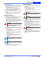
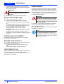
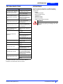
1
www.nilfisk-alto.com FLOORTEC R 580 B DEUTSCH BETRIEBSANLEITUNG FRANÇAIS MANUEL D’UTILISATION ENGLISH NEDERLANDS USER MANUAL GEBRUIKSAANWIJZING B 789 6 5 12 13 14 1 D 15 E 16 2 3 4 S310027 F S310114 G H S310208 S310180 C S310181 I J S310117 K S310209 S310133 S310210 L S310119 S310211 USER MANUAL ENGLISH INTRODUCTION ................................................................................................................................... 2 MANUAL PURPOSE AND CONTENTS ........................................................................................................... 2 TARGET ........................................................................................................................................................... 2 HOW TO KEEP THIS MANUAL ....................................................................................................................... 2 IDENTIFICATION DATA ................................................................................................................................... 2 OTHER REFERENCE MANUALS .................................................................................................................... 2 SPARE PARTS AND MAINTENANCE ............................................................................................................. 2 CHANGES AND IMPROVEMENTS ................................................................................................................. 2 SAFETY ................................................................................................................................................. 2 SYMBOLS ......................................................................................................................................................... 3 GENERAL INSTRUCTIONS ............................................................................................................................. 3 UNPACKING ......................................................................................................................................... 4 MACHINE DESCRIPTION ..................................................................................................................... 4 OPERATION CAPABILITIES ............................................................................................................................ 4 CONVENTIONS ................................................................................................................................................ 4 DESCRIPTION ................................................................................................................................................. 4 TECHNICAL DATA ........................................................................................................................................... 5 ELECTRICAL FUSES ....................................................................................................................................... 6 ACCESSORIES/OPTIONS ............................................................................................................................... 6 USE ........................................................................................................................................................ 7 BATTERY CHECK/SETTING ON A NEW MACHINE ...................................................................................... 7 BATTERY INSTALLATION AND BATTERY TYPE SETTING (WET OR GEL) ................................................ 8 BEFORE START-UP ........................................................................................................................................ 8 STARTING AND STOPPING THE MACHINE .................................................................................................. 8 MACHINE OPERATION ................................................................................................................................... 9 HOPPER DUMPING ......................................................................................................................................... 9 AFTER USING THE MACHINE ...................................................................................................................... 10 WORKING LIGHT ADJUSTMENT .................................................................................................................. 10 MACHINE LONG INACTIVITY ....................................................................................................................... 10 FIRST PERIOD OF USE ................................................................................................................................ 10 MAINTENANCE .................................................................................................................................. 10 SCHEDULED MAINTENANCE TABLE .......................................................................................................... 11 MAIN BROOM HEIGHT CHECK AND ADJUSTMENT .................................................................................. 12 MAIN BROOM REPLACEMENT .................................................................................................................... 12 SIDE BROOM HEIGHT CHECK AND ADJUSTMENT ................................................................................... 13 SIDE BROOM REPLACEMENT ..................................................................................................................... 13 FRAME DUST FILTER CLEANING AND INTEGRITY CHECK ..................................................................... 14 CLOSED POCKET DUST FILTER CLEANING AND INTEGRITY CHECK ................................................... 14 SKIRT HEIGHT AND OPERATION CHECK .................................................................................................. 15 HOPPER LIFTING SYSTEM OIL LEVEL CHECK .......................................................................................... 15 CHARGING THE BATTERIES ....................................................................................................................... 16 SAFETY FUNCTIONS ......................................................................................................................... 16 RUNNING ENABLING SWITCH ..................................................................................................................... 16 EMERGENCY PUSH-BUTTON ...................................................................................................................... 16 HOPPER LIFTING/LOWERING AND OVERTURNING ENABLING SWITCH ............................................... 16 HOPPER LIFTING CYLINDER SAFETY DEVICE VALVE ............................................................................. 16 TROUBLESHOOTING ........................................................................................................................ 17 SCRAPPING ........................................................................................................................................ 17 EC CERTIFICATE OF CONFORMITY ................................................................................................ 18 146 2601 000(1)2005-03 A FLOORTEC R 580 B 1 ENGLISH USER MANUAL INTRODUCTION OTHER REFERENCE MANUALS MANUAL PURPOSE AND CONTENTS – – The purpose of this Manual is to provide the operator with all necessary information to use the machine properly in a safe and autonomous way. It contains information about technical characteristics, operation, machine storage, maintenance, spare parts and safety conditions. Before carrying out any procedure on the machine, the operators and technicians in charge of the machine maintenance must read this manual carefully. Contact an authorised Nilfisk-Alto Service Center in case of doubts regarding the interpretation of the instructions and for any further information. Spare Part List, supplied with the machine. Service manual (that can be consulted at Nilfisk-Alto Service Centers). SPARE PARTS AND MAINTENANCE All necessary operating, maintenance and repair procedures must be carried out by qualified personnel or by Nilfisk-Alto Service Centers (listed at the end of this manual). Only original spare parts and accessories must be used. Call Nilfisk-Alto for service or to order spare parts and accessories, specifying the machine model and serial number. TARGET CHANGES AND IMPROVEMENTS This manual is intended for qualified operators and technicians involved in the machine maintenance. Nilfisk-Alto constantly improves its products and reserves the right to make changes and improvements at its discretion without being obliged to apply such benefits to the machine that were sold previously. Any change and/or addition of accessory must be approved and performed by Nilfisk-Alto. HOW TO KEEP THIS MANUAL The User manual must be kept near the machine, inside an adequate case, far from liquids and other substances that can cause damage to it. IDENTIFICATION DATA The machine model and serial number are marked on the outside, under the seat (28, Fig. B). The machine model year is written in the EC statement and it is also indicated by the first two figures of the machine serial number. This information is useful when requiring machine and engine replacement parts. Use the following table to write down the machine identification data for any further reference. MACHINE model ........................................................ SAFETY The following symbols indicate potentially dangerous situations. Always read this information carefully and take all necessary precautions to safeguard people and property. No accident prevention program is effective without the total cooperation of the person responsible for the machine operation. Most of the accidents that may occur in a factory, while working or moving around, are caused by failure to comply with the simplest rules for exercising prudence. A careful and prudent Operator is the best guarantee against accidents and is essential for successful completion of any prevention program. MACHINE serial number ............................................ 2 FLOORTEC R 580 B 146 2601 000(1)2005-03 A USER MANUAL ENGLISH SYMBOLS DANGER! It indicates a dangerous situation with risk of death for the Operator. WARNING! – WARNING! It indicates a potential risk of injury for people. CAUTION! It indicates a caution or a remark related to important or useful functions. Pay attention to the paragraphs marked by this symbol. NOTE Consult the User manual before performing any procedure. – – – – – – GENERAL INSTRUCTIONS Specific warnings and cautions to inform about potential damages to people and machine are shown below. – – – DANGER! – – – – – – – – To perform maintenance/repair procedures turn the machine ignition key to OFF position and disconnect the battery. This machine must be used by properly trained and authorised personnel only. Children or disabled people cannot use this machine. Keep sparks, flames and smoking materials away from the batteries. During the normal operation explosive gases are released. Do not wear jewels when working near electrical components. Do not work under the lifted machine, if it is not securely fixed. Each time you work under the open hood, ensure that the hood cannot be closed by accident. Do not operate the machine near toxic, dangerous, inflammable and/or explosive powders, liquids or vapours. Battery charging produces highly explosive hydrogen gas. Keep the hood open during battery charging and perform the operation only in well-ventilated areas and far from naked flames. 146 2601 000(1)2005-03 A – – – – – – – – – – – Carefully read all the instructions before carrying out any maintenance/repair procedure. Take all necessary precautions to prevent hair, jewels and loose clothes from being caught in the moving parts of the machine. Do not smoke while charging the batteries. Do not leave the machine unattended with the key inserted in the ignition switch and the parking brake disengaged. Do not use the machine on surfaces with a gradient greater than the one indicated on the machine. Do not wash the machine with direct or pressurised water jets, or with corrosive substances. Do not use compressed air for general cleaning, except for the filters (see the related paragraph). While using this machine, take care not to cause damage to other people, especially children. Do not put any can containing fluids on the machine. The storage temperature must be between 0°C and +40°C. The machine operating temperature must be between 0°C and +40°C. The humidity must be between 30% and 95%. Always protect the machine against the sun, rain and bad weather, both under operation or inactivity condition. The machine cannot be used for towing or pushing objects and/or loads. Do not use the machine as a transport vehicle; the machine maximum capacity is 110 kg, besides the weight of the operator. Do not allow the brooms to operate while the machine is stationary to avoid damaging the floor. In case of fire, possibly use a powder fire extinguisher, not a water one. Do not bump into shelves or scaffoldings, particularly where there is a risk of falling objects. Adjust the operation speed to suit the floor conditions. This machine cannot be used on public roads. Do not tamper with the machine safety guards and follow the ordinary maintenance instructions scrupulously. Do not remove or modify the plates affixed to the machine by the Manufacturer. FLOORTEC R 580 B 3 ENGLISH – USER MANUAL In case of machine malfunctions, ensure that these are not due to lack of maintenance. Otherwise, request assistance from the authorised personnel or from an authorised Service Center. In case of part replacement, order ORIGINAL spare parts from an authorised Dealer or Retailer. To ensure the proper and safe operation of the machine, have the scheduled maintenance, detailed in the related chapter of this Manual, performed by the authorised personnel or an authorised Service Center. The machine must be disposed of properly, because of the presence of toxic-harmful materials (batteries, oils, plastics, etc.), which are subject to standards that require disposal in special centres (see the “Scrapping” chapter). If the machine is used according to the instructions, the vibrations do not cause dangerous situations. The machine vibration level is less than 2.5 m/s2 (EN 1032-96/A1-98). Do not tilt the machine more than 30° from its horizontal position, or the highly corrosive acid could leak out of the batteries. When the machine is to be tilted for maintenance operations, remove the batteries. – – – – – UNPACKING When the machine is delivered, check that the packing and the machine were not damaged during transportation. In case of visible damages, keep the packing and have it checked by the Parcel Service that delivered it. Call the Carrier immediately to fill in a damage claim. Please check that the following items have been supplied with the machine: Technical documents: – Sweeper manual – Spare Parts List – No. 1 main fuse (F0) 150A – Battery connector 4 FLOORTEC R 580 B MACHINE DESCRIPTION OPERATION CAPABILITIES The sweeper is used to sweep dust or light debris on smooth and solid floor, in civil or industrial environment, under safe operation conditions by a qualified Operator. CONVENTIONS Forward, backward, front, rear, left or right are intended with reference to the operator’s position, that is to say on the driver’s seat (27, Fig. B). DESCRIPTION Control panel (See Fig. B) 1. Hopper lifting/lowering enabling switch 2. Horn switch 3. Working light switch (optional) 4. Position for optional switch (rotating light) 5. Display 6. Display selection button for the following operations, in sequence: - Working hours - Last digit of the hours - (dot) - minutes - Battery voltage (V) 7. Discharged battery warning light (red) 8. Semi-discharged battery warning light (yellow) 9. Charged battery warning light (green) 10. Steering wheel 11. Steering wheel inclination adjusting knobs 12. Emergency stop button 13. Position for optional switch 14. Filter-shaker switch 15. Hopper lifting/lowering switch 16. Hopper overturning switch 17. Vacuum activation/deactivation lever 18. Ignition switch 19. Parking brake lock control lever (in combination with pedal, position 26). 20. Drive pedal 21. Right broom lifting/lowering lever 146 2601 000(1)2005-03 A USER MANUAL Left broom lifting/lowering lever (optional) Seat longitudinal position adjusting lever Main broom lifting/lowering lever Front skirt lifting pedal Service brake pedal (parking brake when combined with lever, position 19) 27. Driver seat with safety microswitch 28. Serial number plate 29. Forward/reverse gear switch TECHNICAL DATA Outside view (See Fig. C) 1. Pivoting light (always on when the ignition switch is turned to “I” position) 2. Working light aiming adjusting screws 3. Dust filter cover 4. Hopper 5. Left door 6. Left fastener with locking screw 7. Right opening door 8. Right fastener 9. Working light (optional) 10. Right side broom 11. Left side broom (optional) 12. Main broom 13. Battery compartment hood 14. Rear drive wheels on fixed axis 15. Front steering wheel 16. Left side skirt 17. Right side skirt 18. Front skirt 19. Rear skirt 20. Dust filter container 22. 23. 24. 25. 26. Under-hood compartment (See Fig. V) 1. Hood (open position) 2. Batteries 3. Battery caps 4. Battery connector 5. Main broom motor resettable thermal fuse 6. Right side broom motor resettable thermal fuse 7. Left side broom motor resettable thermal fuse 8. Lamellar fuse box 9. Suction/main broom motor 10. Vacuum fan 11. Drive motor 12. Wiring junction box 13. Drive electronic board 14. Hopper lifting system hydraulic oil tank 15. Battery installation diagram 16. Open hood support rod General Values Working width (with one side broom) 1,050 mm Working width (with two side brooms) 1,310 mm Machine length 1,776 mm Machine width (with one side broom) 1,207 mm Machine width (with two side brooms) 1,310 mm Maximum height, at the steering wheel 1,350 mm Minimum ground clearance (skirts not included) 60 mm Hopper maximum lifting height 1,650 mm Maximum weight liftable by the hopper Minimum/maximum dumping height Minimum turning radius 110 kg 270 mm/1,370 mm 1,690 mm Main broom size Ø 300 mm x 800 mm Side broom size Ø 500 mm Maximum forward speed 7 Km/h Maximum reverse speed 3.5 Km/h Gradeability 16% Hopper capacity 130 litres Front axis weight in running conditions 243 Kg Rear axis weight in running conditions 386 Kg Machine whole weight with 4x6V 180 Ah standard batteries 629 Kg Front steering wheel 4.00 - 4 mm Rear wheels, driving 4.00 - 4 mm Sound level (A Lpa) 66.9 dB(A) Electric motors Values Electrical system voltage 24V 24V, 1.100W, 2.800 rpm Suction/main broom motor Drive motor 24V, 750W, 5.000 rpm Side broom reduction unit 24V, 90W, 85 rpm Filter-shaker motor 24V, 90W, 5,700 rpm Batteries Values Standard batteries No. 4 6V, lead batteries, with acid electrolyte, in serial connection Optional batteries No. 1 24V, lead battery with acid electrolyte Optional batteries (gel or lead, available at Nilfisk retailers) Battery total voltage Usable battery capacity Battery case dimensions Battery compartment max. size Dust vacuuming and filtering Paper dust filter, 5-10 µm Main broom compartment vacuum 146 2601 000(1)2005-03 A ENGLISH Values 24V 330Ah 300x800 mm 360x800x380 mm Values 4.5 m2 7.6 mm H2O FLOORTEC R 580 B 5 ENGLISH USER MANUAL Wiring diagram (See Fig. AF) BE1: Pivoting light (optional) BZ1: Reverse gear buzzer C1: Battery connector EB1: Drive electronic board EB2: Display board ES1: Line electromagnetic switch ES2: Main broom electromagnetic switch ES3: Pump relay ES4: Pump relay F0: Main fuse F1: Key fuse F2: Hydraulic pump fuse F3: Hopper actuator fuse F4: Filter-shaker fuse F5: Service fuse F6: Working light fuse (optional) F7: Right side broom resettable thermal fuse F8: Left side broom resettable thermal fuse (optional) F9: Main broom resettable thermal fuse K1: Ignition switch L1: Right light (optional) L2: Left light (optional) L3: Working light (optional) M1: Drive motor M2: Main broom motor M3: Hydraulic pump M4: Actuator M5: Filter-shaker motor M7: Right side broom motor M8: Left side broom motor (optional) R1: Accelerator potentiometer (pedal in-built) SW0: Emergency switch SW1: Forward/reverse gear switch SW2: Main broom microswitch SW3: Hopper enabling switch SW4: Hopper lifting/lowering switch SW5: Hopper overturning switch SW7: Right side broom microswitch SW8: Left side broom microswitch (optional) SW9: Hopper horizontal position microswitch SW10: Hopper lifted position microswitch SW11: Hopper open position microswitch SW12: Hopper closed position microswitch SW13: Filter-shaker switch SW14: Light switch (optional) SW15: Horn switch SW16: Working light switch (optional) SW17: Safety microswitch (in the seat) SW18: Accelerator pedal microswitch 6 FLOORTEC R 580 B Colour code BK: Black BU: Blue BN: Brown GN: Green GY: Grey OG: Orange PK: Pink RD: Red VT: Violet WH: White Hydraulic diagram (See Fig. AG) 1. Hydraulic oil tank 2. Hydraulic oil filter 3. Hydraulic pump 4. Motor 5. Safety valve 6. Hopper lifting cylinder ELECTRICAL FUSES Under the hood, outside the electrical box, there are the following fuses: – Circuit breakers, which can be reset by pressing the related key: – Main broom motor (5, Fig. V) – Right side broom motor (6, Fig. V) – Left side broom motor (7, Fig. V) (optional) – Lamellar fuses, protected by a transparent plastic cover, which protect the following circuits: – F1 (15A) (the first starting from above): ignition switch – F2 (20A): hydraulic pump – F3 (10A): hopper actuator – F4 (15A): filter-shaker – F5 (10A): auxiliaries – F6 (10A): working lights (optional) – spare 1 (20A) – spare 2 (15A) Inside the electrical box (12, Fig. V), there is the following fuse: – F0 (150A): main (2, Fig. Z). ACCESSORIES/OPTIONS In addition to the standard components, the machine can be equipped with the following accessories/options, according to the machine specific use: – Left side broom; – Main and side brooms with harder or softer bristles; – Antistatic polyester or polyester BIA C dust filter; – Pocket filter; – Pivoting light; – Working light; – Non marking skirt; – Non marking wheels; – Protective roof. For further information concerning the optional accessories, contact Your Retailer. 146 2601 000(1)2005-03 A USER MANUAL USE b) WARNING! On some points of the machine there are some adhesive plates indicating: – DANGER – WARNING – CAUTION – NOTE BATTERY CHECK/SETTING ON A NEW MACHINE 146 2601 000(1)2005-03 A Batteries installed on the machine but dry, that is without electrolyte. 1. Lift the hood (13, Fig. C) and secure it with the rod (16, Fig. V). 2. Remove the battery caps (3, Fig. V). WARNING! Be extremely careful when working with sulphuric acid, as it is corrosive. If it comes in contact with skin or eyes, rinse thoroughly with water and call a physician. Batteries have to be filled up in a properly ventilated area. Use protective gloves. While reading this Manual, the Operator must pay particular attention to these symbols. Do not cover these plates for any reason and immediately replace them if they are damaged. The machine requires one 24V battery, or four 6V batteries in serial connection. The machine can be supplied in one of the following modes: a) Batteries already installed and ready to be used. 1. Lift the hood (13, Fig. C) and secure it with the rod (16, Fig. V). Check that the batteries are connected to the machine through the related connector (4, Fig. V). 2. Disengage the support rod an lower the hood and ensure that it is correctly closed. 3. Insert the ignition key (18, Fig. B) in the control panel and turn it to “I” position (without activating the forward/reverse gear pedal 20, Fig. B). If the green warning light (9, Fig. B) turns on, the battery is ready to be used. If the yellow or red warning light (8 or 7, Fig. B) turns on, it is necessary to charge the battery (see procedure in Maintenance chapter). ENGLISH c) 3. Fill the cells (or each element) of the batteries with sulphuric acid for batteries (density from 1.27 to 1.29 Kg at 25°C) in accordance with the instructions given in the Battery User's Manual. The correct quantity of sulphuric acid is indicated in the Battery Manual. Let the battery rest and fill in with sulphuric acid in accordance with the instructions specified in the Battery manual. 4. Charge the batteries (see the relevant procedure in the Maintenance chapter). Without battery 1. Buy appropriate batteries (see the Technical Characteristics paragraph). For the battery choice and installation, apply to qualified battery retailers. 2. Install the batteries and set the battery type (WET or GEL) on the machine (see the following paragraph). 3. Charge the batteries (see the relevant procedure in the Maintenance chapter). FLOORTEC R 580 B 7 ENGLISH USER MANUAL BATTERY INSTALLATION AND BATTERY TYPE SETTING (WET OR GEL) Battery installation 1. Install the batteries on the machine according to the diagram (15, Fig. V). According to the battery dimensions, check if it is possible to put them inside the related plastic container, supplied with the machine. If the batteries dimensions are larger than the container capacity, use the square guides, supplied with the machine, to ensure the stability inside the battery compartment. WARNING! Non-sealed lead/acid batteries always need an appropriate container to prevent the acid form leaking. Do not install the non-sealed lead/acid batteries without an appropriate container. WET or GEL battery setting STARTING AND STOPPING THE MACHINE Starting the machine 1. Sit in the driver's seat (27, Fig. B) and, using the lever (23) adjust the seat to a comfortable position. 2. Unlock the steering wheel (10, Fig. B) by means of the handle (11) and adjust its tilting according to one's comfort; after the adjustment, release the handle (11) and lightly move the steering wheel to hook it on the internal retainer. 3. From the driver's seat (27, Fig. B), insert the key in the ignition switch (18, Fig. B); turn it to “I” position, without activating the forward/reverse gear pedal (20), then wait (for a few seconds) for the display (5, Fig. B) to turn on and the working hours to appear. Check that the green warning light turns on (9, Fig. B). 4. If the warning light becomes red or yellow (7 or 8, Fig. B) turn the ignition key to “0” position and take it out. Charge the batteries (see the procedure in the Maintenance paragraph). NOTE The seat (27, Fig. B) is equipped with a safety sensor, which allows the machine operation only if the operator is seated on the driver's seat. NOTE The machine factory setting is for lead (WET) batteries. If the setting corresponds to the chosen battery, do not perform the setting procedure. If not, perform the following procedures: 2. According to the installed battery (WET or GEL), perform the setting procedure of the machine electronic board and proceed as follow: – Turn the ignition switch (18, Fig. B) to “0” position. – Lift the hood (13, Fig. C) and secure it with the rod (16, Fig. V). – Disconnect the battery connector (4, Fig. V). – Remove the screws (1, Fig. AD) and take out the right control panel (2) with care. – Install a jumper wire (1, Fig. AE) on the WET connectors (2) for lead battery or on the GEL connectors (3) for gel battery. – Carefully reassemble the control panel (2, Fig. AD) and fix it by using the related screws (1). – Connect the battery connector (4, Fig. V). – Disengage the support rod (16, Fig. V) and close the hood (13, Fig. C). BEFORE START-UP 1. Check that there are no open doors/hoods and that the machine is in normal operating conditions. If the machine has not been used yet after the transportation, check that each block and locking system used for the transportation, have been removed. 2. 8 FLOORTEC R 580 B 5. Disengage the parking brake by pressing the related pedal (26, Fig. B) and unlocking the lever (19). 6. To sweep, start the machine with the hands upon the steering wheel and press the pedal (10, Fig. P). 6a. The forward/reverse direction is selected with the related switch (29, Fig. B) on the left control panel. The drive speed can be adjusted from zero to maximum speed by increasing the pressure exerted on the pedal. 7. Lower the main broom with the lever (24, Fig. B), then turn the suction on with the lever (17, Fig. B). 8. Activate the lever (21, Fig. B) to lower the right side broom. 9. Activate the lever (22, Fig. B) to lower the left side broom, if present. NOTE All brooms (10, 11, 12, Fig. C) can be lifted or lowered when the machine is moving. When the brooms are lifted, they do not turn. When the main broom is lifted, the suction is not operating. 10. To sweep, start the machine with the hands upon the steering wheel (10, Fig. B) and press the pedal (20) correctly. 146 2601 000(1)2005-03 A USER MANUAL Stopping the machine 1. To stop the machine, release the pedal (20, Fig. B). To stop the machine quickly, also push the service brake pedal (26, Fig. B). In case of emergency, press the emergency push-button (12, Fig. B) to immediately stop the machine. To disengage the safety switch (12), turn it in the direction indicated by the arrow. 2. Turn the ignition switch (18, Fig. B) to “0” and remove the key. 3. Engage the parking brake by pressing the brake pedal (26, Fig. B) and by activating the brake lock control lever (19). HOPPER DUMPING 1. 2. 2. Avoid stopping for a long time with the machine in the same position and the brooms rotating: this could create unwanted marks on the floor. To collect light and bulky waste materials, lift the front skirt by activating the pedal (25, Fig. B); do not keep pushing onto the lever for a long time in order not to reduce the suction capability of the machine. WARNING! When operating on wet grounds, it is necessary to operate the lever (17, Fig. B) and turn the suction off to prevent the dust filter from being damaged. 3. For the machine proper operation, the dust filter must be as clean as possible. To clean it while sweeping, proceed as follows: – Lift the main broom by means of the lever (24, Fig. B) to stop the suction. – Press the filter-shaker switch (14, Fig. B) at short intervals. – Then, lower the main broom to restart the suction, and resume operation. While working, repeat the operation every 10 minutes (depending on the dustiness of the area to be cleaned). The maximum dumping height of the hopper is 1,380 mm (Fig. U). To empty the hopper, drive the machine near the dustbin and proceed as follows: – Lift the side and main brooms; – Close the suction by means of the lever (17, Fig. B); – Press the filter-shaker switch (14, Fig. B). WARNING! Always carry out this operation on a level ground to avoid machine unbalance. MACHINE OPERATION 1. ENGLISH WARNING! When lifting and emptying the hopper (4, Fig. C), keep the parking brake engaged with the pedal and lever (26 and 19, Fig. B). 3. 4. 5. Keep people far from the machine and especially from the hopper (4, Fig. C). Press both the enabling switch (1, Fig. B) and the hopper lifting switch (15) to lift the hopper (1, Fig. T) up to the desired position. Press both the enabling switch (1, Fig. B) and the hopper (2, Fig. U) overturning switch (16, Fig. B) and discharge all the debris in the dustbin (1. Fig. U). WARNING! The hopper (2, Fig. U) can be overturned only after having lifted it at a minimum height of 270 mm. 6. To bring the hopper back to its original position (horizontal position), press the enabling switch (1, Fig. B) while pressing the hopper overturning switch (16. Fig. B). NOTE This operation can also be performed when the machine is moving. NOTE When the dust filter is obstructed and/or the hopper is full, the machine cannot collect dust and debris. 4. The hopper (4, Fig. C) should be emptied after each working period and whenever is full. 146 2601 000(1)2005-03 A FLOORTEC R 580 B 9 ENGLISH 7. USER MANUAL Press both the enabling switch (1, Fig. B) and the hopper lowering switch (15) to lower the hopper down to the desired position. WARNING! The hopper can be overturned only if it is not in its original position (horizontal position). 8. The machine is ready to start working again. AFTER USING THE MACHINE After working, before leaving the machine: – Lift the main broom with the lever (24, Fig. B). – Lift the side brooms with the levers (21 and 22, Fig. B). – Close the suction by means of the related lever (17, Fig. B), then press the filter-shaker switch (14, Fig. B) for a short interval; open the suction again. – Dump the hopper (4, Fig. C) (see previous paragraph). – Remove the ignition key from the switch (18, Fig. B). – Engage the parking brake by pressing the brake pedal (26, Fig. B), then activate the brake lock control lever (19). WORKING LIGHT ADJUSTMENT MAINTENANCE The lifespan of the machine and its maximum operating safety are ensured by correct and regular maintenance. The following chart provides the scheduled maintenance. The intervals shown may vary according to particular working conditions, which are to be defined by the person in charge of the maintenance. WARNING! Operations to be carried out with the machine off, the ignition key not inserted and (if required) the battery disconnected. Moreover, carefully read the instructions in the Safety chapter. All scheduled or extraordinary maintenance operations must be performed by qualified personnel, or by an authorised Service Center. This manual describes only the easier and most common maintenance procedures. NOTE For other maintenance procedures contained in the Scheduled Maintenance Table or for extraordinary maintenance operations see the specific Service Manual that can be consulted at any Service Center. If necessary, adjust the working light (9, Fig. C) beam aiming with the screws (22). MACHINE LONG INACTIVITY If you foresee that the machine will not be used for more than 30 days, proceed as follows: – Check that the machine storage area is dry and clean. – Disconnect the battery connector (4, Fig. V). FIRST PERIOD OF USE After the first period of use (first 8 hours) it is necessary to check that the fixing and connecting elements are correctly tightened, that the visible parts are integral and that there are no leakages. 10 FLOORTEC R 580 B 146 2601 000(1)2005-03 A USER MANUAL ENGLISH SCHEDULED MAINTENANCE TABLE Maintenance operation Battery fluid level check Hopper lifting hydraulic system oil level check On delivery Every 10 hours Every 50 hours Every 100 hours Every 200 hours Every 400 hours (1) (1) Motor-to-main broom belt visual inspection and tension check (*) Skirt height and operation check Side and main broom height check Frame dust filter cleaning and integrity check Closed pocket filter cleaning and integrity check Filter-shaker operation check (*) Brake adjustment (*) Nut and screw tightening check Drive wheel gearing chain tension check and cleaning (*) (2) (*) Steering chain cleaning (*) Vacuum hose integrity check (*) Pulley-to-main broom belt replacement (*) Motor-to-main broom pulley V-belt replacement (*) Hopper gasket integrity check (*) Hopper lifted position control microswitch adjustment check (*) Hopper horizontal position control micro-switch adjustment check (*) Motor carbon brush check and replacement (*) Hydraulic oil change (*) (3) (*): For the related procedure, see the Service Manual (1): or before each start-up (2): And after the first 8 running-in hours (3): replace hydraulic oil for the first time after 500 hours, then after 2,000 hours or every year. 146 2601 000(1)2005-03 A FLOORTEC R 580 B 11 ENGLISH USER MANUAL MAIN BROOM HEIGHT CHECK AND ADJUSTMENT 10. Engage the retainer (6, Fig. C) and close the left door (5). NOTE If it is not possible to adjust the print (1, Fig. D) correctly, because the ground pressure at the ends of the broom is different, refer to the Service Manual for the related adjustment procedure. NOTE Brooms of various hardness are available. This procedure is applicable to all types of brooms. 1. Check the main broom for proper ground clearance, proceeding as follows: – Drive the machine on a level ground; – Keep the machine stationary and rotate the main broom for a few seconds; – Stop and lift the main broom, then move the machine; – Check that the main broom print (1, Fig. D), along its length, is from 2 to 4 cm wide. If the print (1) is not within specifications, it is necessary to adjust the broom height, proceeding as described in the following steps. To stop the machine, turn the ignition switch (18, Fig. B) to “0” position. 2. WARNING! Before opening the left door (5, Fig. C) switch the machine off to prevent the belts and pulleys rotation. 3. Remove the screw with a screwdriver, then release the fastener (6, Fig. C). Open the left door (5, Fig. C). Loose the locknut (2, Fig. E). Turn the handwheel (1, Fig E) and remind that: – to decrease the pressure of the broom on the ground, it must be screwed. – to increase the pressure of the broom on the ground, it must be unscrewed. 4. 5. 6. NOTE When the handwheel is completely unscrewed, you have reached the maximum pressure of the broom on the ground. 7. 8. Screw the locknut (2, Fig. E). Perform step 1 again to check the proper adjustment of the main broom height from the ground. When the broom is too worn to be adjusted, replace it as shown in the next paragraph. 9. 12 FLOORTEC R 580 B MAIN BROOM REPLACEMENT NOTE Brooms of various hardness are available. This procedure is applicable to all types of brooms. WARNING! It is advisable to use protective gloves when replacing the main broom because there can be cutting debris between the bristles. 1. 2. 3. 4. 5. 6. 7. 8. 9. 10. 11. 12. 13. Drive the machine on a level ground and activate the parking brake using the pedal and the lever (26 and 19, Fig. B). Turn the ignition switch (18, Fig. B) to “0” position. Open the hood (1, Fig. V) and disconnect the battery connector (4, Fig. V). Disengage the retainer (8, Fig. C) and open the right door (7). Unscrew and remove the knobs (1, Fig. F). Remove the broom compartment cover (1, Fig. G). Remove the broom (1, Fig. H). Check that the drive hub (1, Fig. I) is free from dirt or foreign materials (ropes, rags, etc.) accidentally rolled up. The new broom must be installed with the bristles rows positioned as shown in the figure (2, Fig. I). Install the new broom (3, Fig. I) on the machine and ensure that its mesh (4) correctly fits on the related drive hub (1). Reinstall the broom compartment cover (1, Fig. G) and screw the knobs (1, Fig. F). Engage the retainer (8, Fig. C) and close the right door (7). Carry out the main broom height check and adjustment, as described in the previous paragraph. 146 2601 000(1)2005-03 A USER MANUAL SIDE BROOM HEIGHT CHECK AND ADJUSTMENT SIDE BROOM REPLACEMENT NOTE Brooms of various hardness are available. This procedure is applicable to all types of brooms. NOTE Brooms of various hardness are available. This procedure is applicable to all types of brooms. 1. 2. 3. 4. 5. 6. 7. Check the side brooms for proper ground clearance, proceeding as follows: – Drive the machine on a level ground; – Keep the machine stationary, lower the side brooms and rotate them for a few seconds; – Stop and lift the side brooms, then move the machine; – Check that the side broom prints are, in extension and orientation, as shown in the figure (1 and 2, Fig. J). In case the prints are not within specifications, it is necessary to adjust the broom height, proceeding as described in the following steps. Engage the parking brake using the pedal and the lever (26 and 19, Fig. B). Turn the ignition switch (18, Fig. B) to “0” position. Lift the hood (13, Fig. C) and secure it with the rod (16, Fig. V). For the right side broom, use the lever (1, Fig. K): loosen the ring nut (2) and adjust the register (3) until the correct print is achieved (1. Fig. J). Then fit it on the lever by means of the ring nut (2, Fig. K). For the left side broom, use the lever (4, Fig. K): Loosen the ring nut (5, Fig. J) and adjust the adjuster (6) until the correct print (2) is achieved. Then fit it on the lever by means of the ring nut (5, Fig. K). Perform step 1 again to check the proper adjustment of the side broom height from the ground. When the broom is too worn to be adjusted, replace it as shown in the next paragraph. ENGLISH WARNING! It is advisable to use protective gloves when replacing the side broom because there can be cutting debris between the bristles. 1. 2. 3. 4. 5. 6. 7. 8. Drive the machine on a level ground and activate the parking brake using the pedal and the lever (26 and 19, Fig. B). Turn the ignition switch (18, Fig. B) to “0” position. Activate the lever (21 or 22, Fig. B) to lift the related side broom. From the inside of the side broom, unscrew the 4 nuts (1, Fig. L), then remove the broom and the hub (2) by disengaging it from the shaft (3). Recover the key (4) and the washer (5). At the bench, remove the four screws (6) and separate the broom (8) from the hub (7). Install the new broom (8) onto the hub (7), and tighten the screws (6). Reinstall the new broom with the hub (2) on the machine after seating the key (4). Position the washer (5) and tighten the screw (1). Carry out the side broom height check and adjustment, as described in the previous paragraph. NOTE If necessary, adjust also the side brooms tilting position (see the related procedure on the Service Manual). 146 2601 000(1)2005-03 A FLOORTEC R 580 B 13 ENGLISH USER MANUAL FRAME DUST FILTER CLEANING AND INTEGRITY CHECK CLOSED POCKET DUST FILTER CLEANING AND INTEGRITY CHECK NOTE The polyester closed pocket filters are normally kept clean by activating the electric filter-shaker supplied with the machine. If necessary, they can be cleaned using the procedure indicated below. When the filtration surfaces are no longer suitable, the filter must be replaced. NOTE Besides the standard paper filter, optional polyester filters are also available. The following procedure is applicable to each type of filter. 1. Drive the machine on a level ground and activate the parking brake using the pedal and the lever (26 and 19, Fig. B). 2. Turn the ignition switch (18, Fig. B) to “0” position. 3. Lift the hood (13, Fig. C) and secure it with the rod (16, Fig. V). 4. Disconnect the battery connector (4, Fig. V). Remove the filter cover (2, Fig. M) by disengaging it from the retainers (1). 5. Disconnect the electric connector (1, Fig. N) from the filter-shaker. 6. Remove the filter-shaker support frame handwheels (2, Fig. N). 7. Remove the filter-shaker support frame (3, Fig. N). 8. Pull out the dust filter (4, Fig. N) upwards. 9. In an appropriate outdoor area, clean the filter shaking it on a level and clean surface, tapping the side (1, Fig. O), opposite the wire gauze (2). Complete the cleaning by using compressed air (3) at max. 6 bars, blowing only from the side protected by the wire gauze (2), at a minimum distance of 30 cm. According to the filter type, observe the following cautions: – Paper filter (standard): do not use water or detergents to clean it; the filter can be damaged; – Polyester filter (optional): To clean it, see the above-mentioned instructions. If necessary, for a better cleaning, it is allowed to wash the filter with water and non-lathering detergents. This provides better quality cleaning but reduces the life of the filter, which will have to be replaced more frequently. The use of inadequate detergents can damage the filter. Check the filter body for tears. 10. Clean the filter compartment rubber seal (1, Fig. P) along its perimeter and check its integrity. If necessary, replace it. 11. Install in the reverse order of removal (steps from 8 to 1). NOTE When reinstalling the filter, the wire gauze (2, Fig. O) must be facing upward. 14 FLOORTEC R 580 B 1. 2. 3. 4. 5. 6. 7. 8. 9. 10. 11. 12. 13. Drive the machine on a level ground and activate the parking brake using the pedal and the lever (26 and 19, Fig. B). Turn the ignition switch (18, Fig. B) to “0” position. Lift the hood (13, Fig. C) and secure it with the rod (16, Fig. V). Remove the filter cover (2, Fig. M) by disengaging it from the retainers (1). Unscrew the knobs (1, Fig. AA) and remove the brackets (2). Pull out the dust filter (1, Fig. AB) upward, and remove it after disconnecting the electrical connector (2) from the filter-shaker. Disassemble the polyester filtering surface, as indicated by the following steps; these procedures must be carried out in a suitable outdoor area and the Operator must be suitably equipped (gloves, mask, glasses). Remove the filter-shaker motor (1, Fig. AC) by unscrewing the two fixing screws. Open the filter-shaker motor support unit (2, Fig. AC) completely and release the filtering pocket tension rods (3). Remove all the filtering pocket tension rods (4, Fig. AC). Open the upper retaining cord (5, Fig. AC) of the closed pocket filter to remove it from the upper frame (6). Remove the internal pocket separator (7, Fig. AC). Clean the polyester fiber surface (8, Fig. AC) from the dirty side, using an external vacuum cleaner, spreading it out completely or cleaning pocket by pocket. At the same time, clean both the surfaces of the pocket separator (7, Fig. AC) removing anything deposited on them. Check the filtering surface for tears. In case of tears, replace it. It is also possible to use compressed air (max. 6 bars), blowing the air from the clean side towards the dirty side. WARNING! Do not wash the filter with water. The polyester fibber can shrink and become unusable. 146 2601 000(1)2005-03 A USER MANUAL 14. Reassemble all the filter components in the reverse order of disassembly. 15. If necessary, clean the filter compartment rubber seal (3, Fig. AB) along its perimeter and check its integrity. If necessary, replace it. 16. Reassemble all the components in the reverse order of disassembly. SKIRT HEIGHT AND OPERATION CHECK Side skirts 1. Drive the machine on a level ground that is suitable for checking the skirt height. 2. Engage the parking brake using the pedal and the lever (26 and 19, Fig. B). 3. Turn the ignition switch (18, Fig. B) to “0” position. 4. Disengage the retainers (8 and 6, Fig. C) and open the right and left doors (7 and 5). 5. Check the side skirt (2, Fig. F) integrity. Replace the skirts when they have cuts (1, Fig. Q) larger than 20 mm or cracks/tears (2) larger than 10 mm (for skirt replacement, see the Service Manual). 6. Check that side skirt (2, Fig. F) height from ground is within 0 – 3 mm (Fig. R). After loosening the screws (3, Fig. F), if necessary, adjust the skirt position. Then tighten the screws (3). Front and rear skirt 7. Remove the main broom, as described in the related paragraph. 8. Check the front (1, Fig. W) and rear (2) skirts for integrity. Replace the skirts when they have cuts (1, Fig. Q) larger than 20 mm or cracks/tears (2) larger than 10 mm (for skirt replacement, see the Service Manual). 9. Check that the front (1, Fig. W) and rear (2) skirts rub lightly on the floor but are not completely lifted from the ground (Fig. S). After loosening the screws (3, Fig. W), adjust the skirt position if necessary. Then tighten the screws (3). 146 2601 000(1)2005-03 A ENGLISH 10. Press the front (25, Fig. B) skirt lifting pedal completely, and check that the front skirt lifts 5 cm approximately. Release the pedal and check that the skirt returns to the initial position and not in an intermediate position. If necessary, adjust the skirt lifting cable (1, Fig. X), by means of the adjuster (2) on the left front side of the skirt (for the front skirt control cable replacement, see the Service Manual). 11. Reassemble in the reverse order of disassembly. HOPPER LIFTING SYSTEM OIL LEVEL CHECK WARNING! These operations must be performed with the hopper (4, Fig. C) in its original position (as shown in the figure). 1. 2. 3. 4. 5. Engage the parking brake using the pedal and the lever (26 and 19, Fig. B). Lift the hood (1, Fig. V) and secure it with the rod (16). Check that the hydraulic oil level in the tank (14, Fig. V) is between the MIN (minimum level) and MAX (maximum level) marks shown in figure Y. If necessary, add hydraulic oil - viscosity grade 32 cSt - through the plug (1, Fig. Y). Disengage the support rod (16, Fig. V) and close the hood (1). FLOORTEC R 580 B 15 ENGLISH USER MANUAL CHARGING THE BATTERIES WARNING! Battery charging produces highly explosive hydrogen gas. Charge the batteries in well-ventilated areas and away from naked flames. Do not smoke while charging the batteries. Keep the hood open while recharging the battery. WARNING! Be extremely careful when charging the battery as there may be battery fluid leakages. The battery liquid is corrosive. If it comes in contact with the skin or eyes, rinse thoroughly with water and consult a physician. 1. Drive the machine on a level ground and activate the parking brake using the pedal and the lever (26 and 19, Fig. B). 2. Turn the ignition switch (18, Fig. B) to “0” position. 3. Lift the hood (13, Fig. C) and secure it with the rod (16, Fig. V). 4. Check the correct level of electrolyte inside the battery; if necessary, top up through the caps (3, Fig. V). Leave the caps (3) open for the next battery charge. If necessary, clean the upper surface of the batteries. 5. Check that the battery charger is appropriate, referring to its instructions. The battery charger voltage rating is 24 V. Use a battery charger suitable for the type of batteries installed. 6. Disconnect the battery connector (4, Fig. V) and connect it to the external battery charger. 7. Connect the battery charger to the electrical system and charge the batteries. 8. When the recharging is complete, disconnect the battery charger from the electrical system and from the battery connector (4, Fig. V). 9. Check the correct level of electrolyte inside the batteries and close the caps (3, Fig. V). 10. Reconnect the battery connector (4, Fig. V) to the machine. 11. Disengage the support rod (16, Fig. V) and close the hood (13, Fig. C): the machine is ready to be used. 16 FLOORTEC R 580 B SAFETY FUNCTIONS The machine is equipped with the following safety functions. RUNNING ENABLING SWITCH It allows the machine to run only if the operator is on the driver's seat (27, Fig. B). EMERGENCY PUSH-BUTTON It is located in an easily accessible position (12, Fig. B); it has to be pressed in case of emergency, to stop all the machine functions. HOPPER LIFTING/LOWERING AND OVERTURNING ENABLING SWITCH It is in the position (1, Fig. B) and must be pressed and held to activate the hopper lifting/lowering and overturning switches. HOPPER LIFTING CYLINDER SAFETY DEVICE VALVE It is located on the hopper lifting cylinder. It stops the hopper in the position it has reached (without possibility for it to lower accidentally) if the hydraulic system piping, feeding the lifting cylinder should break. 146 2601 000(1)2005-03 A USER MANUAL TROUBLESHOOTING TROUBLE ENGLISH SCRAPPING REMEDY Check that the battery After having turned the ignition connector (4, Fig. V) is correctly key (18, Fig. B) to “I” position, the connected to the machine. display does not illuminate and Check the F1 (1, Fig. Z) and F0 the machine does not work. (2, Fig. Z) fuse integrity The machine does not move when pressing the accelerator pedal. Turn the ignition switch to “0” position, then turn it to “I” position being careful not to activate the accelerator pedal during this operation The main broom does not work Check that the related fuse (5, Fig. V) is not deactivated; otherwise reactivate it by means of the related key The side brooms do not work Check that the related fuse (6 or 7, Fig. V) is not deactivated; otherwise reactivate it by means of the related key Have the machine scrapped by a qualified scrapper. Before scrapping the machine, remove the following components: – Battery – Polyester dust filter – Main and side brooms – Hydraulic oil – Hydraulic oil filter – Electronic boards – Plastic components and hoses WARNING! The removed components must be disposed of properly according to the Law in force. The machine operates only when Re-charge the battery. If the stationary, otherwise the red problem persists, replace the warning light turns on. battery. Check if the dust filter (4, Fig. N) is clogged The machine collects little debris/dust Check if the hopper (4, Fig. C) is full Check that the skirts (16, 17, 18, 19, Fig. C) are not broken or incorrectly adjusted Check if the brooms (10, 11, 12, Fig. C) are at the correct height The battery autonomy is low Install a battery with greater capacity: 240 Ah The hopper does not lift Check the fuse (F2, Fig. Z) integrity Check the fuse (F3, Fig. Z) integrity The hopper does not lift The hopper does not lower The filter-shaker does not work Check that the hopper is lifted from the ground at an height greater than 270 mm Before lowering the hopper by means of the related switch (15, Fig. B), check that the hopper has returned to the horizontal position by means of the related switch (16, Fig. B). Check that the main broom is lifted with the lever (24, Fig. B) Check the fuse (F4, Fig. Z) integrity For further information, refer to the Service Manual, available at any Nilfisk-Alto Service Center. 146 2601 000(1)2005-03 A FLOORTEC R 580 B 17 ENGLISH USER MANUAL EC CERTIFICATE OF CONFORMITY (&GHFODUDWLRQRIFRQIRUPLW\ $OWR'HXWVFKODQG*PE+ *XLGR2EHUGRUIHU6WUDH '%HOOHQEHUJ 3URGXFW 6ZHHSHU 0RGHO )/2257(&5% 'HVFULSWLRQ 9 7KHGHVLJQRIWKHDSSOLDQFHFRUUHVSRQGV WRWKHIROORZLQJSHUWLQHQWUHJXODWLRQV (&0DFKLQH'LUHFWLYH(& (&/RZ9ROWDJH'LUHFWLYH((& (&(0&'LUHFWLYH((& $SSOLHGKDUPRQL]HGVWDQGDUGV (1(1(1(1 (1 (1(1 $SSOLHGQDWLRQDOVWDQGDUGVDQGWHFKQLFDO VSHFLILFDWLRQV ',1(1 ,(& 'LSO,QJ:ROIJDQJ1LHXZNDPS 7HVWVDQGDSSURYDOV 18 FLOORTEC R 580 B %HOOHQEHUJ 146 2601 000(1)2005-03 A AF SW14 L1 YEBK CL1 SW15 VT BK BE1 BK SW13 BN M5 SW10 apre 0V 0V SW11 PK PK BU BU VT VT BU SW5 RD M4 SW12 chiude WHBK SW4 WH SW9 GY GY GYBK GYBK ES3 OG ES4 0V 0V M3 RD BK SW3 BK SW8 0V BNBK SW7 GYBK WHBK SW2 VTBK F6 BN F5 BU OGBK 0V OGBK OG OG ES2 YE YE BK BK F4 VT F3 WH F2 RD 0V M2 RD K1 F1 RD EB2 SW0 RD RD OG 0V M8 GY BN A A A F9 F7 F8 RD RD F0 M7 ES1 RD RD RD BK EB1 OG M1 RD + PK - C1 + 0V SW18 SW17 - VT VT SW1 BN OG 0V 0V BZ1 BU 24V BATTERIES WH OG R1 S310215 AG 6 5 200 BAR 200 BAR 3 110 BAR 70 BAR 4 750cc / HYDRAULIC OIL 32 cSt 2 1 S310132 M N V S310121 O S310122 P S310124 Q S310192 R S310037 T S S310038 W U S310125 S310212 S310039 S310126 X S310127 S310128 Y Z Nilfisk-ALTO HEADQUARTER DENMARK Nilfisk-Advance Group Sognevej 25 2605 Brøndby Denmark Tel: (+45) 43 23 81 00 SUBSIDIARIES S310129 AA S310130 AB AUSTRALIA Nilfisk - ALTO 48 Egerton St. PO box 6046 Silverwater NSW 2128 Australia Tel: (+61) 2 8748 5966 Fax: (+61) 2 8748 5960 AUSTRIA ALTO Österreich GmbH Nilfisk-Advance AG Metzgerstrasse 68 5101 Bergheim/Salzburg Austria Tel : (+43) 662 456 400 11 Fax: (+43) 662 456 400 34 E-mail: verkauf@nilfisk-alto.at www.nilfisk-alto.at BRAZIL Wap do Brasil Ltda. Rua das Palmeiras, 350-Bairro Capela Velha 83.705-500 – Araucária - Paraná Brasil Tel: (+55) 41 2106 7400 Fax (+55) 41 2106 7403/7404 E-mail: [email protected] S310186 AC 7 S310187 AD 5 2 1 CZECH REPUBLIC ALTO Ceskà republika s.r.o. Zateckých 9 14000 Praha 4 Czech Republic Tel. (+420) 24 14 08 419 Fax (+420) 24 14 08 439 E-mail: [email protected] 1 DENMARK Nilfisk-ALTO Division of Nilfisk-Advance A/S Industrivej 1 9560 Hadsund Denmark Tel: (+45) 72 18 21 00 Fax: (+45) 72 18 21 05 E-mail: salg@nilfisk-alto.dk E-mail: service@nilfisk-alto.dk www.nilfisk-alto.dk 1 1 8 6 3 4 CANADA ALTO Canada 24 Constellation Road Rexdale Ontario M9W 1K1 Canada Tel: (+1) 416 675 5830 Fax: (+1) 416 675 6989 S310213 AE Nilfisk-ALTO Food Division Division of Nilfisk-Advance A/S Blytækkervej 2, 9000 Aalborg Denmark Tel: (+45) 72 18 21 00 Fax: (+45) 72 18 20 99 E-mail: scanio.technology@nilfisk-alto.dk www.nilfisk-alto.com FRANCE Nilfisk-ALTO ALTO France SA Aéroparc 1 19 rue Icare 67960 Entzheim France Tel: (+33) 3 88 28 84 00 Fax: (+33) 3 88 30 05 00 E-mail: info@nilfisk-alto-fr www.nilfisk-alto.com 2 1 S310145 S310214 GERMANY Nilfisk-ALTO Division of Nilfisk-Advance A/S Guido-Oberdorfer-Str. 2-8 89287 Bellenberg Germany Tel: (+49) (0) 730 67 20 Fax: (+49) (0) 730 67 23 10 E-mail: info@nilfisk-alto.de Info-export@nilfisk-alto.de www.nilfisk-alto.de SPAIN Nilfisk-ALTO Division of Nilfisk-Advance S.A. Torre D´Ara Paseo del Rengle, 5 Pl. 10 08302 Mataró Barcelona Spain Tel: (+34) 93 741 24 00 Fax : (+34) 93 757 80 20 E-mail: info@nilfisk-alto.es www.nilfisk-alto.com GREAT BRITAIN Nilfisk-ALTO Division of Nilfisk-Advance Ltd. Bowerbank Way Gilwilly Industrial Estate Penrith Cumbria CA11 9BQ Great Britain Tel: (+44) 1 768 86 89 95 Fax: (+44) 1 768 86 47 13 E-mail: sales@nilfisk-alto.co.uk www.nilfisk-alto.co.uk SWEDEN ALTO Sverige AB Aminogatan 18, Box 40 29 431 04 Mölndal Sweden Tel: (+46) 31 706 73 00 Fax: (+46) 31 7067341 E-mail: info@nilfisk-alto.se www.nilfisk-alto.se HUNGARY ALTO Hungary Kft Csengery ut. 119 8800 Nagykanizsa Hungary Tel: (+36) 93 509 701 Fax: (+36) 93 509 704 MALAYSIA ALTO DEN-SIN Malaysia Sdn Bhd SD14, Jalan KIP 11 Taman Perindustrian KIP Sri Damansara 52200 Kuala Lumpur Malaysia Tel: (+603) 6274 6913 Fax: (+603) 6274 6318 E-mail: [email protected] NETHERLANDS Nilfisk-ALTO ALTO Nederland B.V. Camerastraat 9 1322 BB Almere The Netherlands Tel: (+31) 36 5460 760 Fax: (+31) 36 5460 700 E-mail: [email protected] Postbox 60112 1320 AC Almere The Netherlands NORWAY ALTO Norge AS Bjørnerudveien 24 1266 Oslo Norway Tel: (+47) 22 75 17 70 Fax: (+47) 22 75 17 71 E-mail: info@nilfisk-alto.no www.nilfisk-alto.no SINGAPORE ALTO DEN-SIN Singapore Pte. Ltd. No. 17 Link Road Singapore 619034 Singapore Tel: (+65) 6268 1006 Fax: (+65) 6268 4916 Web: www.densin.com E-mail: [email protected] USA ALTO U.S. Inc. 16253 Swingley Ridge Road Suite 200 Chesterfield Missouri 63017-1544 USA Tel.: (+1) 636 530 0871 Fax: (+1) 636 530 0872 E-mail: [email protected] ALTO U.S.Inc 2100 Highway 265 Springdale Arkansas 72764 USA Tel: (+1) 479 750 1000 Fax: (+1) 479 756 0719 E-mail: [email protected] ALTO U.S.Inc 1100 Haskins Road Bowling Green Ohio 43402 USA Tel: (+1) 419 352 75 11 Fax: (+1) 419 353 71 87 E-Mail: [email protected] ALTO Cleaning Systems, Inc. 12249 Nations Ford Road Pineville North Carolina 28134 USA Tel: (+1) 704 971 1240 Fax: (+1) 704 971 1241 E-mail: info@nilfisk-advance.us www.nilfisk-alto.com