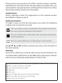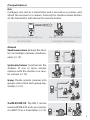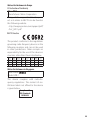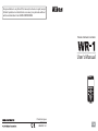
1
No reproduction in any form of this manual, in whole or in part (except
for brief quotation in critical articles or reviews), may be made without
written authorization from NIKON CORPORATION.
Wireless Remote Controller
User's Manual
Printed in Japan
SB3B01(11)
6MBJ0811-01
En
Thank you for your purchase of an WR-1 wireless remote controller.
Read both this manual and the documentation provided with your
camera before using the product, and keep these instructions where
they will be read by all who use the product.
Controller Settings
Unless otherwise noted, the explanations in this manual assume
that default settings are used.
Symbols and Conventions
To make it easier to find the information you need, the following
symbols and conventions are used:
This icon marks cautions, information that should be read before use to prevent damage to the product.
This icon marks notes, information that should be read before
using the product.
This icon marks references to other pages in this manual.
The 1, 3, 4, and 2 symbols represent up, down, left, and right on
the multi selector.
Illustrations
Instructions referring to cameras with ten-pin remote terminals are
accompanied by illustrations of the D800, those referring to cameras
with accessory terminals by illustrations of the D7100.
Before proceeding, confirm that the package contains the following:
❑ WR-1 wireless remote controller
❑ User’s Manual (this manual)
❑ Warranty
❑ Soft case
❑ MC-37 cable (for ten-pin remote terminals)
❑ MC-38 cable (for accessory terminals)
Batteries are not included.
Principal Features
Basic
Configure one unit as a transmitter and a second as a receiver, and
attach the receiver to a camera. Pressing the shutter-release button
on the transmitter will release the camera shutter.
Pressing the shutter-release button on
the transmitter…
…releases the shutter on the cameras
connected to the receivers.
Advanced
Simultaneous release: Release the shutters on multiple cameras simultaneously (0 12).
Synchronized release: Synchronize the
shutters of one or more remote
cameras with the shutter on a master camera (0 13).
Groups: Divide remote cameras into
groups and control each group separately (0 14).
A
B
C
The WR-R10/WR-T10: The WR-1 can be
used with WR-R10 units as receivers
or a WR-T10 as a transmitter (0 15).
i
Wireless Regulation Data
Trade Name:
Model: WR-1
FCC ID: CGJ4149EA
IC: 4634A-4149EA
Compliance Statement
This device complies with Part 15 of the
FCC Rules and with RSS-210 of Industry
Canada. Operation is subject to the following two conditions:
(1) this device may not cause harmful interference, and
(2) this device must accept any interference received, including interference
that may cause undesired operation.
Ce dispositif est déclaré conforme à la
Partie 15 de la Réglementation FCC et
à la norme RSS-210 d’Industrie Canada.
Son fonctionnement est soumis aux deux
conditions suivantes:
(1) cet appareil ne doit pas causer d’interférences nuisibles, et
(2) cet appareil doit accepter les interférences reçues, y compris celles susceptibles de causer un fonctionnement indésirable.
Modifications not expressly approved by
Nikon Corporation could void the user’s
authority to operate the equipment.
This equipment has been tested and
found to comply with the limits for a
Class B digital device, pursuant to Part
15 of the FCC Rules. These limits are designed to provide reasonable protection
against harmful interference in a residential installation. This equipment generates, uses and can radiate radio frequency
ii
energy and, if not installed and used in
accordance with the instructions, may
cause harmful interference to radio communications. However, there is no guarantee that interference will not occur in
a particular installation. If this equipment
does cause harmful interference to radio
or television reception, which can be determined by turning the equipment off
and on, the user is encouraged to try to
correct the interference by one or more
of the following measures:
• Reorient or relocate the receiving antenna.
• Increase the separation between the
equipment and receiver.
• Connect the equipment into an outlet
on a circuit different from that to which
the receiver is connected.
• Consult the dealer or an experienced
radio/TV technician for help.
Radiofrequency radiation exposure information:
The radiated output power of the device
is far below the FCC radio frequency exposure limits.
Nevertheless, the device shall be used in
such a manner that the potential for human contact during normal operation is
minimized.
FCC CAUTION
Changes or modifications not expressly
approved by Nikon Corporation could
void the user’s authority to operate the
equipment.
Nikon Inc., 1300 Walt Whitman Road,
Melville, New York
11747-3064, U.S.A. Tel.: 631-547-4200
Notices for Customers in Europe
EC Declaration of Conformity
Nikon WR-1
Manufacturer: Nikon Corporation
A copy of the original DoC for this product as it relates to R&TTE can be found at
the following website:
http://imaging.nikon.com/support/pdf/
DoC_WR-1.pdf
R&TTE Directive
This product conforms to the regulations
governing radio-frequency devices in the
following countries and can not be used
in other jurisdictions. Nikon accepts no
responsibility for the use of this device in
countries other than those listed below.
AT BE BG CY CZ DK EE FI
FR DE GR HU IE IT LV LT
LU MT NL PL PT RO SK SI
ES SE GB IS LI NO CH TR
Notice for Customers in Singapore
Trade Name:
Model: WR-1
This device complies with radio-frequency regulations. The content of certification labels not affixed to the device
is given below.
Complies with
IDA Standards
DA103423
iii
For Your Safety
To prevent damage to your Nikon product or injury to yourself or to others, read the following safety precautions in their entirety before using this product. Keep these safety
instructions where all those who use the product will read them.
The consequences that could result from failure to observe the precautions listed in this
section are indicated by the following symbol:
This icon marks warnings, information that should be read before using this
Nikon product to prevent possible injury.
WARNINGS
A Do not disassemble. Failure to observe this precaution could result in fire, electric
shock, or other injury. Should the product break open as the result of a fall or other
accident, remove the batteries and take the product to a Nikon-authorized service
representative for inspection.
A Keep out of reach of children. Failure to observe this precaution could result in injury.
In addition, note that small parts constitute a choking hazard. Should a child swallow any part of this product, consult a physician immediately.
A Cut power immediately in the event of malfunction. Should you notice smoke or an unusual smell coming from the product, immediately turn the product off. Continued
operation could result in injury. Once the product has cooled, remove the batteries
and take the product to a Nikon-authorized service representative for inspection.
A Do not use in the presence of flammable gas. Failure to observe this precaution could
result in explosion or fire.
A Keep dry. Do not immerse in or expose to water or rain. Failure to observe this precaution could result in fire or electric shock.
A Do not handle with wet hands. Failure to observe this precaution could result in electric shock.
A Do not remain in contact with the camera or controller for extended periods while the products
are on or in use. Parts of the product become hot. Leaving the product in direct contact with the skin for extended periods may result in low-temperature burns.
A Do not expose to high temperatures. Do not leave the product in a closed vehicle under
the sun or in other areas subject to extremely high temperatures. Failure to observe
this precaution could result in fire or in damage to the casing or internal parts.
iv
A Follow the instructions of hospital and airline personnel. This product emits radio frequency radiation that could interfere with medical or navigational equipment.
Turn the product off during takeoff and landing and when so directed by airline
or hospital staff.
A Observe proper precautions when handling batteries. Batteries may leak, rupture, or overheat if improperly handled. Observe the following precautions when handling batteries for use in this product:
• Turn the product off before replacing the batteries.
• Use only AA alkaline or NiMH batteries. Do not combine old and new batteries or
batteries of different makes or types.
• Be sure to insert in the correct orientation.
• Do not attempt to recharge non-rechargeable batteries. When recharging NiMH
batteries, follow instructions, use compatible chargers only, and charge each pair
as a set.
• Do not short or disassemble batteries or attempt to remove or otherwise damage
the battery insulation or casing.
• Do not transport or store with metal objects such as necklaces or hairpins. For
transport, place batteries in a plastic bag or other container to insulate the terminals.
• Do not expose to flame or to excessive heat, immerse in or expose to water, or
subject to physical force.
• Batteries are prone to leakage when fully discharged. To prevent damage to the
product, be sure to remove the batteries and disconnect the product from the
camera when no charge remains or if the product will not be used for an extended period.
• Should liquid from damaged batteries comes in contact with clothing, eyes, or
skin, immediately rinse the affected area with plenty of water.
• Discontinue use immediately should you notice any changes in the battery, such
as discoloration or deformation.
• Dispose of used batteries in accord with local regulations. Prior to disposal, insulate the terminals with tape. Fire, overheating, or rupture may result should metal
objects come into contact with the terminals.
v
Notices
• No part of this manual may be reproduced, transmitted, transcribed, stored in a retrieval system, or translated into any language in any form, by any means, without
Nikon’s prior written permission.
• Nikon reserves the right to change the specifications of the hardware and software
described in this manual at any time and without prior notice.
• Nikon will not be held liable for any damages resulting from the use of this product.
• While every effort has been made to ensure that the information in this manual is
accurate and complete, we would appreciate it were you to bring any errors or omissions to the attention of the Nikon representative in your area (address provided separately).
This product, which contains encryption software developed in the United States, is
controlled by the United States Export Administration Regulations and may not be exported or re-exported to any country to which the United States embargoes goods.
The following countries are currently subject to embargo: Cuba, Iran, North Korea, Sudan, and Syria.
CAUTION
RISK OF EXPLOSION IF BATTERY IS REPLACED BY AN INCORRECT TYPE.
DISPOSE OF USED BATTERIES ACCORDING TO THE INSTRUCTIONS.
Notices for Customers in Europe
This symbol indicates that electrical and electronic equipment is to be collected separately.
The following apply only to users in European countries:
• This product is designated for separate collection at an appropriate collection point. Do not dispose of as household waste.
• Separate collection and recycling helps conserve natural resources and prevent negative consequences for human health and the environment that might result from
incorrect disposal.
• For more information, contact the retailer or the local authorities in charge of waste
management.
vi
Table of Contents
Principal Features .............................................................................................................. i
Wireless Regulation Data ...............................................................................................ii
For Your Safety ..................................................................................................................iv
Notices.................................................................................................................................vi
Introduction
1
Parts of the WR-1 ..............................................................................................................1
The Display .........................................................................................................................2
Inserting Batteries
4
Connecting WR-1 Units
6
Using the WR-1: The Basics
8
Step 1: Position the Tx/Rx/OFF Switches ..................................................................8
Step 2: Set the Units to the Same Channel .............................................................8
Step 3: Pair the Units .......................................................................................................9
Step 4: Group the Units ............................................................................................... 10
Step 5: Take Pictures ..................................................................................................... 10
Controlling Multiple Cameras
12
12
Simultaneous Release .................................................................................................. 12
Synchronized Release .................................................................................................. 13
Groups ............................................................................................................................... 14
The WR-R10/WR-T10..................................................................................................... 15
vii
Menus
16
16
Using the Menus ............................................................................................................ 17
SPECIAL ............................................................................................................................. 18
Interval Timer Photography ................................................................................. 18
Release Hold Time ................................................................................................... 20
Relay ............................................................................................................................. 21
Release Delay ............................................................................................................ 22
ID Mode............................................................................................................................. 23
viii
Viewing and Changing Camera Settings (D7100 Only)
24
24
Troubleshooting
26
26
Specifications
2
28
8
A Life-Long Learning
As part of Nikon’s “Life-Long Learning” commitment to ongoing product support and education, continually-updated information is available online at the following sites:
• For users in the U.S.A.: http://www.nikonusa.com/
• For users in Europe and Africa: http://www.europe-nikon.com/support/
• For users in Asia, Oceania, and the Middle East: http://www.nikon-asia.com/
Visit these sites to keep up-to-date with the latest product information, tips, answers to frequently-asked questions (FAQs), and general
advice on digital imaging and photography. Additional information
may be available from the Nikon representative in your area. See the
following URL for contact information: http://imaging.nikon.com/
Introduction
This section offers an overview of product controls and displays.
Parts of the WR-1
1 LED (red/green) ...................................9
2 Display .....................................................2
3 Group buttons (A, B, C, D)............... 10
4 SEL (device) button .................11, 24
5 y (illuminator) button ...................3
6 Shutter-release button .................. 10
7 Release.....................................................7
8 Multi selector
n
Japa
IN
DE
MA
Sa
mp
H1 le
ES 104
040
07A
2 -1
A0
1
The number following
the hyphen inside battery
chamber is product serial
number.
9 Ten-pin terminal cover .....................6
Ten-pin remote terminal..................6
10 MENU (menu) button ................... 16
11 Fn (function) button ...................... 11
12 Tx/Rx/OFF switch ..............................8
13 Strap eyelet
14 Mounting foot ......................................7
15 Battery-chamber cover ....................4
A The Multi Selector
Move cursor up
Select highlighted item
Cancel and return
to previous menu
Select highlighted item or
display sub-menu
Move cursor down
1
The Display
1
2
3 4 5 6
7
8
9
13
12
10
11
Tx/Rx/OFF switch set to Tx (transmitter)
1
2
3 4 5 6
13
12
7
8
11
Tx/Rx/OFF switch set to Rx (receiver)
Description
1 If Tx/Rx/OFF switch is set to Tx, a is displayed and unit functions
as transmitter; if switch is set to Rx, b is displayed and unit functions as receiver.
0
8
2 Indicates whether unit links to other units via pairing (j) 9, 23
or ID (i).
3 ID mode name. Not displayed in pairing mode.
2
23
4 Displayed when controls are locked.
3
5 Indicates whether beeps will sound.
16
6 Battery level. Displayed only when unit is not connected to camera.
5
Description
7 Current channel.
0
8
8 Last three digits of unit serial number (or, if unit has been assigned 1, 23
unit ID, current body number of from #01 to #20).
9 Last three digits of unit serial number (or, if unit has been assigned 25
unit ID, current body number) of selected receiver in each group.
10 Number of receivers in each group (up to 20).
14
11 Currently selected group (A, B, C, or D).
10
12 Wireless signal strength.
—
13 Feature selected in transmitter mode.
• INT: Interval timer
• RHT: Release hold time
• SYNC: Synchronized release
18
20
13
Feature selected in receiver mode.
• RLY: Relay photography
• DLY: Release delay
21
22
A The y Button
Pressing the y button illuminates the display and control backlights
for about 20 seconds, making the unit easier to use in the dark.
A Control Lock
To prevent accidental operation of the multi selector and the group,
MENU, and SEL buttons, press and hold the z button until f appears
in the display to indicate that these controls are locked (disabled).
Press and hold the z button again to re-enable the controls.
3
Inserting Batteries
The WR-1 is powered by two AA alkaline or nickel-metal hydride
(NiMH) batteries. To insert batteries:
1 Open the battery-chamber cover.
Japa
E IN
MAD
Sam
pl
H1 e
ES 104
0400
7A
n
Unlatch and open the battery-chamber
cover.
2 Insert the batteries.
Insert two AA batteries in the orientation
shown.
3 Close the battery-chamber cover.
4
Japa
E IN
MAD
Sam
pl
H1 e
ES 104
0400
7A
n
Be sure the cover is securely latched.
A Units Connected to Cameras
When connected to a camera (0 6), WR-1 units are powered by the
camera; batteries are not required.
A Standby Mode
If no operations are performed for the length of time selected for
STBY p (0 16), transmitters will enter standby and their displays will
turn off to save power. Units that are connected to a camera will turn
off automatically when the camera is turned off.
D Receiver Units
To save power when receivers are not connected to a camera, slide the Tx/Rx/OFF switches to
OFF when the devices are not in use.
A Battery Level
The battery level for units not connected to
cameras is displayed as shown at right; be sure
the batteries have sufficient charge (units connected to cameras do not display the battery
level). Battery level is shown as follows:
• c: Charge remaining.
• d: Batteries low. Ready spare batteries.
• e: Batteries exhausted. Replace batteries.
To ensure that the display is as accurate as possible, select the correct
battery type in the BATTERY menu (0 17). Choose from LR6 (alkaline)
and HR6 (NiMH).
5
Connecting WR-1 Units
Connect the units to the cameras they will be used to control.
1 Open the ten-pin terminal cover.
Open the terminal cover as shown.
Ten-pin terminal
2 Connect the supplied ten-pin or accessory terminal cable.
Use the supplied MC-37 cable when connecting receivers to cameras with ten-pin remote
terminals, the MC-38 when connecting receivers to cameras with accessory terminals.
Keeping the 1 mark on the cable’s ten-pin
connector aligned with the white w mark
next to the ten-pin terminal, insert the connector as shown and
tighten the screw to lock it in place.
3 Connect the cable to the camera.
If the camera is equipped with a ten-pin remote terminal, align the 1 mark on the
MC-37 connector with the white w mark next
to the camera ten-pin remote terminal and
insert the connector as shown. Tighten the
screw to lock the cable in place.
If the camera is equipped with an accessory
terminal, align the 1 mark on the MC-38 connector with the 1 mark next to the camera
accessory terminal and insert the connector
as shown.
6
A Fixing Units in Place
The WR-1 can be mounted on the camera accessory shoe as shown at right.
Once the unit is in place, it can be angled as
shown at right.
To remove the WR-1, angle it as shown in Figure 1 or 2, and then press
the release (q) and slide the unit off the accessory shoe (w). The unit
can only be removed when angled as shown.
Figure 1
Figure 2
If desired, the WR-1 can be mounted on a tripod or an optional SK-7
bracket. Using the SK-7 places the WR-1 at the same level as the camera and allows pictures to be taken using the camera’s built-in flash
or optional flash units and other accessories to be mounted on the
camera accessory shoe.
D The Accessory Shoe
The camera’s built-in flash can not be used when the WR-1 is mounted
on the accessory shoe. If the flash pops up automatically, select P, S, A,
or M mode and then lower the flash to prevent it firing.
7
Using the WR-1: The Basics
The instructions that follow describe how to control a single camera
using two WR-1 units, one functioning as a transmitter and the other
as a receiver.
Step 1: Position the Tx/Rx/OFF Switches
Slide the Tx/Rx/OFF switch for the transmitter
to Tx and the switch for the receiver to Rx. The
units will turn on and display the information
shown below.
Tx (transmitter)
Rx (receiver)
Step 2: Set the Units to the Same Channel
Press 1 or 3 to choose from channels 1 to 15.
Transmitters must be set to the same channel
as the receivers they control.
8
Step 3: Pair the Units
Follow the steps below to pair the units. Units can be paired only
with other devices on the same channel.
1 Set the units to pairing mode.
Press the MENU button to display
the menus, then highlight PAIRING
in the LINK MODE menu and press
z. Repeat for the second unit.
2 Display the PAIRING menus.
Highlight PAIRING and press 2. Repeat for the second unit.
3 Select EXECUTE on both units.
Place the units close together, then highlight
EXECUTE and press z on both devices simultaneously.
If pairing is successful, the message at right
will be displayed and the LED will flash alternately red and green. If the message NO
RESPONSE is displayed, repeat Step 3.
The menus will be displayed when pairing is
complete. Press the MENU buttons to close
the menus.
LED
9
Step 4: Group the Units
Each receiver can be placed in any of four groups (A, B, C, and D). A
transmitter can then be used to control the different groups separately by selecting the appropriate group before operating the
transmitter controls. Transmitters will only control receivers in the
selected group.
To choose a group, use the group buttons. The
group name appears in the display.
Group buttons
Step 5: Take Pictures
The shutter-release button on the transmitter
performs the same functions as the camera
shutter-release button whether pressed halfway or all the way down. See the camera manual for details.
10
A Traffic Level
The traffic on each channel can be
gauged by pressing 2 for about a second. The traffic level for each channel
is shown by an icon; choosing a lowtraffic channel improves performance.
Note that the display varies depend- (No icon)
ing on when it was last updated; when
multiple WR-1 units are used, their No traffic
displays will not necessarily show the
same traffic levels.
Heavy
traffic
A Erasing Pairing Data
Selecting DELETE in the WR-1 PAIRING menu lists the devices with
which the unit is paired, identified by the last three digits of their serial
numbers. Highlight a device and press z. A confirmation dialog will
be displayed; highlight YES and press z to erase the pairing data for
the selected device.
A ID Mode
In ID mode, connections between WR-1 units can be established
based on the unit name rather than device pairing (0 23).
A The Fn Button
The transmitter Fn button performs the same function as the Fn button on the camera to which the receiver is connected (D4, D800/800E,
D7100, and D5200 cameras only; for the latest information on supported cameras, visit the websites listed on page viii). For more information, see the camera manual.
A Device Selection
To control a specific receiver, press the SEL button on the transmitter
and highlight the receiver in the device selection menu.
11
Controlling Multiple Cameras
This section describes the ways in which multiple receivers can be
used to control more than one camera at a time.
Simultaneous Release
If the transmitter and receivers are paired (0 9), on the same channel (0 8), and in the same group (0 10), pressing the transmitter
shutter-release button all the way down will simultaneously release
the shutters on all cameras to which receivers have been attached.
12
Synchronized Release
To synchronize the shutters of one or more remote cameras with the
shutter on a master camera, attach the receivers to the remote cameras and the transmitter to the master camera. The master camera
must be equipped with a ten-pin remote terminal.
1 Connect the controllers.
Connect the transmitter (set to Tx) to the master camera (any camera with a ten-pin remote terminal) and the receivers (set to Rx) to
the remote cameras.
2 Configure the controllers.
Pair all controllers and set them to the same channel and group
(0 8, 9, 10).
3 Set the transmitter to SYNC mode.
Press 4 on the transmitter to enable sync
mode and confirm that k appears in the
display.
4 Take pictures.
The shutters on all cameras will be released when the shutter-release button on the master camera is pressed all the way down.
13
Groups
Remote cameras can be divided into up to four groups (A, B, C, and
D). The cameras in each group can be controlled separately by using the transmitter group buttons to select the desired group before
pressing the shutter-release button.
A
B
C
A Group Size
The transmitter shows the number of receivers
in the current group.
14
The WR-R10/WR-T10
WR-1 units can be used with WR-R10 and WR-T10 wireless remote
controllers (available separately).
WR-R10
WR-R10
WR-T10
WR-R10
WR-A10
WR-1 units must be in pairing mode before they can be paired with
WR-R10 or WR-T10 wireless remote controllers; pairing instructions
for the WR-1 are identical to those given on page 9, while those for
the WR-R10/WR-T10 can be found in the manual provided with the
devices. When selecting channels, note that the WR-R10/WR-T10
support channels 5, 10, and 15 only; set the WR-1 to the same channel as the WR-R10/WR-T10. Neither the WR-R10 nor WR-T10 offer
group selection. Select Group A when using a WR-1 with WR-R10
units; when a WR-T10 is used, it will control receivers in all groups.
15
Menus
The menus contain the items listed below. To
display the menus, press the MENU button.
Item
Description
LINK MODE Choose whether to link to other units via pairing or ID.
BODY NO. Select unit ID (body number) of from #01 to #20 (0 23). Unit IDs
are required for ID mode, but also simplify task of organizing units
in pairing mode. ID replaces last three digits of serial number in
unit display.
16
ID-NAME
Enter ID mode name (0 23).
PAIRING
Pair unit with other devices (0 9), delete pairing data (0 11), or
select LIST to view all devices with which unit is currently paired,
identified by last three digits of their serial numbers.
m
Highlight items and press 2 to enable or mute audio feedback;
items for which feedback is enabled are indicated by checks.
Press 4 to exit when settings are complete.
• BUTTON: Beep sounds when control is used.
• RELEASE: When D600, D7100, D5200, or D3200 is connected,
beep sounds when shutter on camera selected with SEL button is released.
• WARNING: Beep sounds twice when error occurs (0 26).
LCD o
Adjust display contrast.
STBY p
Choose how long transmitter display remains on when no operations are performed (0 5).
Item
Description
BATTERY
To ensure accuracy of battery level display, select option that
matches type of battery inserted in device. Choose from LR6 (AA
alkaline) and HR6 (rechargeable AA NiMH).
SPECIAL
Use transmitter for interval timer photography (INT; 0 18) or
choose transmitter release hold time (RHT; 0 20), or configure
receiver as relay (RLY; 0 21) or choose receiver release delay
(DLY; 0 22). To disable above functions, select DISABLE.
VERSION
View unit firmware version.
Using the Menus
Follow the steps below to select options in the menus.
1 Select an item.
Press 1 or 3 to highlight items and press 2
to view options for the highlighted item.
2 Select an option.
Press 1 or 3 to highlight the desired option
and press z to select.
17
SPECIAL
The SPECIAL menu is used to configure transmitters for interval timer photography and to choose the maximum duration for bulb photography, or to configure receivers to relay transmitter commands
to a second receiver and to choose the delay before the shutter is
released in response to transmitter commands.
Interval Timer Photography
Configure transmitters to release the shutters of remote cameras automatically at preset intervals.
1 Select SPECIAL on the transmitter.
Press the MENU button on the transmitter to
display the menus, then highlight SPECIAL
and press 2.
2 Select INT.
In the transmitter SPECIAL menu, highlight
INT and press 2 to display the options shown
at right.
3 Choose the interval.
Highlight INTERVAL and press 2. The options shown at right will be displayed; press
4 or 2 to highlight minutes or seconds and
1 or 3 to change. Choose an interval longer
than the slowest anticipated shutter speed
(maximum 60 minutes) and allow time for the camera to record
images, as the camera may be forced to skip intervals if the time
allotted is too short. Press z to return to the interval timer menu
when settings are complete.
18
4 Choose the number of intervals.
Highlight NUM OF SHOTS and press 2. The
options shown at right will be displayed;
press 1 or 3 to choose the number of intervals. Press z to return to the interval timer
menu when settings are complete.
5 Choose the starting trigger.
Highlight START WITH RELEASE and press 2.
Highlight one of the following options and
press z.
• ON: Interval timer photography starts when
the transmitter shutter-release button is
pressed.
• OFF: Interval timer photography starts automatically after the
delay selected for INTERVAL.
A Pairing
Pairing can not be performed while interval timer photography is enabled.
A Interrupting Interval Timer Photography
To end interval timer photography before all pictures are taken, select
DISABLE in the SPECIAL menu, press the transmitter shutter-release
button or press 4 on the multi selector, or turn off the transmitter.
19
Release Hold Time
Choose how the remote cameras respond when the transmitter
shutter-release button is held all the way down.
• TIME: The transmitter shutter-release button can be used for long
time-exposures; shooting ends automatically after a selected
time.
• SINGLE SHOOT: Only one picture will be taken regardless of how
long the button is pressed.
1 Select SPECIAL on the transmitter.
Press the MENU button on the transmitter to
display the menus, then highlight SPECIAL
and press 2.
2 Select RHT.
In the transmitter SPECIAL menu, highlight
RHT and press 2 to display the options
shown at right.
3 Choose an option.
• TIME: Highlight TIME and press 2. The options shown at right will be displayed; press
4 or 2 to highlight minutes or seconds and
1 or 3 to choose the maximum shooting
time for long time-exposures (up to 60 minutes). Press z to exit when settings are complete.
• SINGLE SHOOT: Highlight SINGLE SHOOT and press z.
20
Relay
Receivers can be configured to relay transmitter commands to another receiver, increasing transmitter range and allowing signals to
be transmitted around obstacles.
Transmitter
Relay
Receiver
1 Configure the relay.
On the unit that will act as the relay, slide the
Tx/Rx/OFF switch to Rx. Press the MENU button
to display the menus, then highlight SPECIAL
and press 2. Highlight RLY and press z to
configure the unit to act as a relay.
2 Configure the remaining units.
Slide the Tx/Rx/OFF switch on one of the remaining units to Tx to configure it as a transmitter, and the switch on the other unit to Rx
to configure it as a receiver.
3 Take photographs.
Position the units. When the shutter-release button on the transmitter is pressed all the way down, the relay unit will pass the signal to the receiver, and the receiver will release the shutter on the
camera to which it is connected.
21
Release Delay
Choose how long a receiver waits to release the shutter after the
transmitter shutter-release button is pressed all the way down. Different delays can be used for different receivers, allowing shutter
release to be staggered over a series of cameras using a single transmitter.
1 Select SPECIAL on the receiver.
Press the MENU button on a receiver to display the menus, then highlight SPECIAL and
press 2.
2 Select DLY.
In the receiver SPECIAL menu, highlight DLY
and press 2 to display the options shown at
right.
3 Choose the delay.
Highlight DELAY and press 2. The options
shown at right will be displayed; press 4 or
2 to highlight a digit and 1 or 3 to choose
a delay (maximum 60.0 seconds). Press z to
return to exit when settings are complete.
Repeat Steps 1–3 for the remaining receivers as required.
22
ID Mode
While in pairing mode pairing is used to establish links between units
before shooting begins (0 9), in ID mode units automatically link
to others with the same name. Note that ID mode is available with
WR-1 units only; pairing must be used to link with WR-R10/WR-T10
wireless remote controllers.
1 Select ID mode.
Press the MENU button to display the menus.
Highlight LINK MODE and press 2, then
highlight ID and press z to select ID mode.
2 Choose a name.
Highlight ID-NAME and press 2 to display
the text-entry dialog shown at right. Enter a
name of up to eight characters using 4 or 2
to position the cursor and 1 or 3 to enter
characters; to choose the character type, use
the group buttons (press A for the letters A–Z, B for the numbers
0–9, and C for symbols). Press z to proceed when entry is complete.
3 Choose a unit ID.
The unit ID (body number) is used to differentiate between receivers with the same name:
each unit with the same name must have
a unique unit ID. Highlight BODY NO. and
press 2 to display the dialog shown at right.
Choose a unit ID between 01 and 20 and press z.
4 Configure the remaining units.
Repeat Steps 1–3 to configure the remaining units, using the name
selected in Step 2 and a unique unit ID for each unit.
23
Viewing and Changing Camera Settings (D7100 Only)
When receivers are attached to D7100 cameras, camera settings can
be viewed and changed in the transmitter display.
1 Display the device list.
Press the transmitter SEL button to
display a list of the cameras to which
receivers are currently connected.
2 View camera settings.
Cameras that support remote setting display
and adjustment are indicated by a r icon.
Highlight a supported camera and press 2 to
view camera settings. Press 1 or 3 to scroll
the display.
3 Adjust camera settings.
Settings that can be adjusted remotely are
indicated by a r icon. Highlight a setting and
press 2 to view options, then select an option and press z to transmit the selecting
option to the camera.
24
A Receiver Status
The status of receivers that are connected to
D7100 cameras is shown as follows:
• g (still image mode): The transmitter shutterrelease button can be used to take photographs.
• h (movie mode): The transmitter shutter-release button can be used
to begin and end movie recording. REC flashes while recording is in
progress.
• LV (live view): The transmitter shutter-release button can be used for
live view photography.
• BULB (bulb photography): The shutter on the remote camera stays open
while the transmitter shutter-release button is pressed all the way
down.
• TIME (time photography): The shutter on the remote camera opens
when the transmitter shutter-release button is pressed all the way
down and closes when the button is pressed all the way down a
second time.
To view the other receivers in the same group, press and hold the
transmitter group button while pressing 1 or 3.
25
Troubleshooting
If wireless remote controllers fail to function as expected, check the
list of common problems below before consulting your retailer or
Nikon representative.
The unit does not turn on (no indicators appear in the display):
• If the unit is not connected to a camera, confirm that the batteries are
inserted in the correct orientation (0 4). If the problem persists, replace
the batteries with fresh batteries or with fully charged rechargeable batteries.
• If the unit is connected to a camera, confirm that the cable is correctly
connected and that the camera is on (0 6).
The camera does not respond to the transmitter shutter-release button:
• Confirm that the receiver is on the same channel and in the same group
as the transmitter (0 8, 10).
• If PAIRING is selected for LINK MODE, select PAIRING > LIST and confirm
that the transmitter is listed, indicating that the transmitter and receiver
are paired. If the transmitter is not listed, pair the devices as described
on page 9.
• If ID (supported with WR-1 units only) is selected for LINK MODE, confirm that all units have the same name (0 23).
• Confirm that the receiver is connected to the camera (0 6).
• The shutter can not be released. Check the camera.
The unit beeps twice and the camera shutter is not released:
• The shutter can not be released. Check the camera.
• Check that the receivers do not share the same body number.
NOT DETECTED: No paired or linked units in the selected group can be detected on the selected channel.
NO RESPONSE: Reattempt pairing after placing the units closer together and
confirming that they are on the same channel (0 8, 9).
#00 IS DUPLICATED: The current unit ID (body number) is shared by other
receivers with the same name. Select a unique unit ID (0 23).
26
D Precautions for Use
• Controllers must be securely attached to the camera to prevent
camera malfunction. Remove units that are not in use; carrying a
camera in a bag or by the strap with a WR-1 attached risks damage
to the camera or the WR-1 in the event that the camera is exposed
to strong physical shocks or vibration.
• Transmitter and camera shutter-release buttons can not be used
when cameras other than the D7100 are in remote control (ML-L3)
release mode.
A Compatibility
Wireless remote controllers can not be used with D1-series cameras or
the MB-D100. They can be used with the F100, D2X, D2Xs, D2Hs, and
D200, but the shutter can not be released with the F100 in self-timer
mode, while the D2X, D2Xs, D2Hs, and D200 will temporarily display
O if the exposure meters are activated after the unit is attached.
27
Specifications
Wireless Remote Controller WR-1
Type
WR-1
Supported cameras
SLR cameras with ten-pin remote or accessory terminals
Wireless
Channels
1 (2.405 GHz), 2 (2.410 GHz), 3 (2.415 GHz), 4 (2.420 GHz),
5 (2.425 GHz), 6 (2.430 GHz), 7 (2.435 GHz), 8 (2.440 GHz),
9 (2.445 GHz), 10 (2.450 GHz), 11 (2.455 GHz),
12 (2.460 GHz), 13 (2.465 GHz), 14 (2.470 GHz), and
15 (2.475 GHz)
Range (line of sight)
Approximate range between WR-1 units at height of about
1.2 m (4 ft) is 120 m (394 ft); varies with weather conditions
and presence or absence of obstacles
Maximum number of
units
Up to 20 units (including a maximum of 3 transmitters) can
be used at a time
Power source
Power is supplied by camera if connected; when not connected to camera, unit is powered by two AA alkaline or
nickel-metal hydride (NiMH) batteries
Power consumption
Approximately 1 W maximum
Operating environment
• Temperature: –20 °C – +50 °C (–4 °F – +122 °F)
• Humidity: 85% or less (no condensation)
Approximate dimensions
50 × 115 × 27.5 mm (2.0 × 4.5 × 1.1 in.)
(W × H × D)
Weight
28
Approximately 90 g (3.2 oz), body only
No reproduction in any form of this manual, in whole or in part (except
for brief quotation in critical articles or reviews), may be made without
written authorization from NIKON CORPORATION.
Wireless Remote Controller
User's Manual
Printed in Japan
SB3B02(11)
6MBJ0811-02
En