1
Autofocus Speedlight
SB-28
Instruction Manual
En
E
Foreword
Congratulations. You are now the proud owner of the Nikon
Autofocus Speedlight SB-28, a flash unit offering sleek new styling
and simple push-button operation. When used with Nikon SLR
cameras, the SB-28’s extensive capabilities range from 3D MultiSensor Balanced Fill-Flash, today’s most advanced flash
technology, to full manual operation.
To get the most out of your new flash unit, please read this manual
before use.
WARNING—To avoid injury
• Do not fire the flash directly into a person’s eyes at close
range as this may damage the retina, leading to partial or
complete blindness.
• Avoid touching the front of the flash head while using the
SB-28. The flash head generates significant heat during
normal operation, which could cause burns.
• Do not expose the SB-28 to water as this may result in
electric shock or cause the unit to catch on fire.
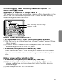
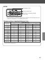
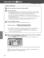
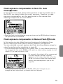
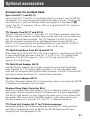
Determine which group your camera belongs to.
In this manual, Nikon SLR cameras are divided into seven groups
(I to VII) unless otherwise noted. First consult the camera group
table to see which group your camera belongs to. Then as you read
the manual, you will find specific information on how to use the
SB-28 with your particular camera.
Please open the front fold-out page for easy reference.
2
Camera groups and available flash modes
Group
Camera
name
Flash
operation
T
T
L
Ⅰ Ⅱ
F5
F100
F90X/N90s1
F90-Series/
N90 1
F80-Series/
N80-Series 1,2,3
F70-Series/
N70 1,2
3D Multi-Sensor
Balanced
Fill-Flash 7
P.26-30
Multi-Sensor
Balanced
Fill-Flash 7
Matrix
Balanced
Fill-Flash
Center-Weighted
P.26-30
Fill-Flash/Spot
Fill-Flash
F4-Series
F65-Series/
N65-Series1,3
F-801s/
N8008s 1
F-801/
N80081
Pronea 600i/
6i 1,3
Ⅲ
F-601/
N6006 1
F-601M/
N6000 1
P.31-32
P.33-34
P.31-32
P.33-34
Ⅳ
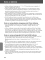
Ⅴ
Ⅵ
Ⅶ*
F60-Series/
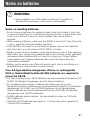
N60 1
F50-Series/
N50 1
F-401x/
N5005 1
F-501/
N2020 4
F-401s/
N4004s 1
F-401/
N4004 1
F-301/
N2000 4
FM3A
FA
FE2
FG
NikonosV 5
F3-Series 6
New FM2
FM10
FE10
P.35-37
Programmed
TTL AutoFlash
P.38-39
Standard
TTL Flash
A
M
P.26-30
P.40-41
Non-TTL
Auto Flash
P.42-43
Manual Flash
P.46-51
FP High-Speed
Flash Sync
P.49-51
Repeating
Flash
P.52-55
: Available
Sold exclusively in the USA.
2
F80-Series/N80-Series, F70-Series/N70 cannot perform FP High-Speed Flash Sync.
3
Center-Weighted Fill-Flash is not possible.
4
Sold exclusively in the USA and Canada.
5
An optional sync cord for land use is required.
1
: Not available
Optional flash Unit coupler AS-4 or AS-7 is required. With AS-17, Standard
TTL flash (p. 40-41) is possible, but not Repeating flash.
7
3D Multi-Sensor Balanced Fill-Flash and Multi-Sensor
Balanced Fill-Flash are generally referred to as Automatic
Balanced Fill-Flash with TTL Multi Sensor.
6
* For cameras such as the Nikon F or Nikon F2, refer to Group VII. TTL Auto Flash mode cannot
be performed with cameras in this group. If flash is fired with the t indicator appeared on
the LCD panel, the flash fires at full output.
For details on the SB-28’s available TTL Auto Flash operations,
see the separate Quick Reference sheet.
3
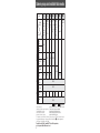
Speedlight parts
Built-in bounce card (P.61)
Built-in wide flash adapter (P.21)
External power source
terminal (P.85)
Flash head (P.13)
Red-eye reduction lamp (P.76)
External power source
terminal (for European
market)* (P.85)
Light sensor for Non-TTL
Auto Flash operation (P.42)
AF assist illuminator LED (P.81)
Flash head tilting/rotating
lock release button (P.13)
Battery chamber lid (P.12)
Mounting foot
locking wheel (P.14)
Mount pin (P.14)
For cameras featuring
a safety lock system.
Hot-shoe contacts (P.14)
Mounting foot (P.14)
Tilting angle scale (P.60)
Rotating angle scale (P.60)
LCD panel (P.5)
Terminal cover
TTL multiple flash terminal (P.66)
Control buttons (P.10)
Sync/multiple flash terminal (P.70)
Ready-light (P.16)
* Because the European version of the SB-28 comes with a different shaped connector, Nikon
DC Units SD-7, SD-8 and the Power Bracket Unit SK-6 are not compatible.
4
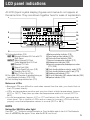
LCD panel indications
All LCD (liquid crystal display) figures and marks do not appear at
the same time. They are shown together here for ease of explanation.
1
6
7
8
2
3
9
10
11
4
12
13
5
1 Flash mode indicator (P.22)
t Ø Automatic Balanced Fill-Flash with TTL
Multi-Sensor
tø Matrix Balanced Fill-Flash,
Center-Weighted/Spot Fill-Flash
t Standard TTL Flash
ƒ Manual Flash (P.46)
% FP High-Speed Flash sync (P.49)
" Repeating Flash (P.52)
˙ Non-TTL Auto Flash (P.42)
2 Film speed (ISO)/number of repeating flashes per
frame/frequency indicators (P.18 / P.52)
3 Flash shooting range indicator bars (P.13)
14
4 Red-eye reduction indicator (P.76)
5 Zoom-head position indicator (P.19)
6 Flash output level indicator (P.50)
7 Exposure compensation indicator (P.72)
8 Underexposure indicator (P.28)
9 Exposure compensation/underexposure value
(P.72 / P.28)
10 Flash shooting distance scale (m: meter) (P.13)
11 Flash shooting distance scale (ft: feet) (P.13)
12 Standby mode indicator (P.15)
13 AF assist illuminator LED canceled indicator (P.82)
14 Aperture indicator (P.42)
Notes on LCDs
• Because LCDs are difficult to read when viewed from the side, you should look at
the LCD panel directly.
• LCDs are temperature sensitive and may turn black at high temperatures (approx.
60°C or 140°F). They clear up when the temperature returns to normal (20°C or
68°F).
• In cold temperatures (approx. 5°C or 41°F and below), the LCDs’ response time
slows down. This is typical of LCDs and no cause for concern. LCDs will function
properly once the temperature returns to normal (20°C or 68°F).
NOTE
Using the SB-28 in dim light
Press the . button to turn the illuminator on. Press the button again to turn it off. The illuminator
turns off automatically after approx. 16 sec. when the SB-28 is not in use.
5
Tips on using this manual
Take some test shots.
Before taking important flash photographs, take some test shots to
ascertain the SB-28 is working as desired in the mode(s) you have
selected.
Use only Nikon-approved equipment.
The SB-28 is designed for use with Nikon cameras, lenses, and
accessories.
—Using cameras or accessories other than those specified by Nikon may damage
the SB-28.
—Nikon cannot be held responsible for malfunctions caused by using the SB-28 in
ways not specified in this manual, or using the SB-28 with a camera made by
another manufacturer.
6
About this manual
• This instruction manual consists of the main manual plus a
separate Quick Reference sheet. The Quick Reference sheet
provides an overview of the SB-28’s capabilities and features,
while the main manual supplies detailed information on all
aspects of the SB-28.
• Because explanations in this manual are based on the operation
of the SB-28 only, please consult the instruction manual provided
with your camera for specific information on its use.
Notices used in this manual
Denotes important points where caution is required.
NOTE Denotes a useful point that should be remembered for
future reference.
Determine what type of Nikkor lenses you are using.
Nikkor lenses are divided into two groups unless otherwise noted.
Nikkor lenses
with a built-in CPU*
• D- or G-type Nikkor lenses
• IX Nikkor lenses**
• Non-D/G-type AF Nikkor lenses***
• AI-P-type Nikkor lenses
Nikkor lenses
without a built-in CPU*
• AI-S-type or AI-type Nikkor lenses
• Nikon Series E lenses
• AI-modified Nikkor lenses and others
* CPU (Central Processing Unit) acts as an on-board computer.
** IX Nikkor lenses are designed for use with the Nikon Advanced Photo System (IX240) format
SLR camera body only and cannot be used with 35mm SLR cameras.
***Except AF Nikkor lenses for the F3AF
7
Contents
Foreword ········································································································2
Camera groups and available flash modes ··················································3
Speedlight parts ····························································································4
LCD panel indications ··················································································5
Tips on using this manual ··············································································6
About this manual ··························································································7
Using control buttons ··················································································10
Getting started ······················································································11
Loading batteries ························································································12
Adjusting the flash head / Selecting the distance scale ····························13
Attaching the SB-28 to the camera ····························································14
Turning the SB-28 on and off / Standby function ········································15
The ready-light ····························································································16
Test firing ····································································································17
Setting the ISO film speed ··········································································18
Adjusting the zoom-head position ························································19-20
Setting the built-in wide flash adapter ························································21
Selecting a flash mode ················································································22
Basic operation ····················································································23
t flash modes ····················································································24-25
TTL Auto Flash t Mode (For cameras in Group I)······························26-30
TTL Auto Flash t Mode (For cameras in Group II) ····························31-32
TTL Auto Flash t Mode (For cameras in Group III)····························33-34
TTL Auto Flash t Mode (For cameras in Group IV) ··························35-37
TTL Auto Flash t Mode (For cameras in Group V) ····························38-39
TTL Auto Flash t Mode (For cameras in Group VI) ··························40-41
Non-TTL Auto Flash ˙ Mode (For cameras in all groups) ··················42-43
8
Advanced operation ············································································45
Manual Flash ƒ Mode
(For cameras in all groups) ································································46-51
Repeating Flash " Mode ······································································52-55
Guide Numbers for determining correct aperture in ƒ
and " flash modes ············································································56-57
Bounce flash operation ··········································································58-61
Close-up flash operation in TTL Auto Flash t Mode ························62-64
Multiple flash operation in t and ƒ flash modes ····························65-70
Exposure compensation in flash photography
(For cameras in all groups) ································································71-75
Red-eye reduction control (For cameras in Group I [except F5]
and Pronea 600i/6i) ··················································································76
Rear-curtain flash sync ··········································································77-78
Additional information ······································································79
Checking the correct exposure (For cameras in all groups) ······················80
Autofocus flash operation in dim light
(For autofocus cameras only) ····························································81-82
Optional accessories ··············································································83-85
Tips on Speedlight care ··············································································86
Notes on batteries ··················································································87-88
Troubleshooting ······················································································89-90
Specifications ························································································91-95
9
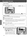
Using control buttons
By pressing a single button, you can activate frequently used
functions. When two buttons are pressed simultaneously, you
can activate functions which are not necessary to set each time.
For easy reference, refer to the chart on the back of the built-in
bounce card.
M ZOOM ONLY
ZOOM
MODE
SEL
+
-
NO AF ILL
ON /STBY
FLASH
(m) / (ft)
ON/OFF
One-button operations
'
To adjust the zoom-head position (P.19-20)
µ
To set the flash mode (P.22)
[
To select and set various functions and values
{
To increase values
}
To decrease values
~
To test fire the flash (P.17)
.
To illuminate the LCD panel (P.5)
=
To turn power on and off (P.15)
Two-button operations
'+{
To set or cancel automatic zoom-head adjustment (Buttons must be
pressed for 2 sec.) (P.19-20)
'+[
To readjust the zoom-head position, if built-in wide flash adapter is
broken off accidentally (P.21)
µ+}
To turn the AF assist illuminator LED on or off (P.81-82)
µ+=
To cancel or set the standby function (Buttons must be pushed after
the flash is turned off.) (P.15)
.+=
To select the distance scale (meters or feet) (P.13)
(Buttons must be pushed after the flash is turned off.)
10
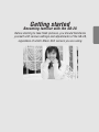
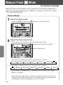
Getting started
Becoming familiar with the SB-28
Before starting to take flash pictures, you should familiarize
yourself with various settings and adjustments of the SB-28,
regardless of which Nikon SLR camera you are using.
11
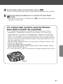
Loading batteries
Four penlight batteries (1.5V or lower) of any of the following types
may be used:
•
•
•
•
AA-type
AA-type
AA-type
AA-type
alkaline-manganese (1.5V)
lithium (1.5V)
NiCd (rechargeable) (1.2V)
Ni-MH (Nickel Metal Hydride) (rechargeable) (1.2V)
NOTE : AA-type high-power manganese batteries are not recommended
for use with the SB-28.
—See pages 87-88, Notes on batteries.
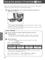
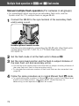
1 Open the battery chamber lid.
four penlight batteries following the + and – symbols
2 Install
inside the chamber. Close the battery chamber lid.
• Various optional external power source DC Units are available for use with
the SB-28. See page 85, Using an external power source.
Do not mix battery types or brands, or use old with new batteries.
12
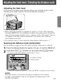
Adjusting the flash head / Selecting the distance scale
Adjusting the flash head
Hold down the flash head tilting/rotating lock release button while
adjusting the flash head to the horizontal/front position.
• The flash head tilts/rotates from the
horizontal/front position to:
90° (up)
–7° (down)
180° (left)
90° (right)
• The flash head has click stops at 30°, 60°
and 90° (to the right), 30°, 60°, 90° 120°,
150° and 180° (to the left), –7° (down), and
45°, 60°, 75° and 90° (up).
• When the = button is pressed for approx. 0.5 sec. after adjusting
the flash head to the horizontal/front position, the power turns on and the
flash shooting range indicator bars _ appear on the LCD panel. They do
not appear if the flash head is adjusted to a position other than the
horizontal/front position.
• The indicator bars _ blink when the flash head is tilted down to –7°.
Selecting the distance scale (meters/feet)
Set the distance scale on the LCD panel to either meters (m) or feet (ft).
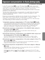
1 Press the = button for approx. 0.5 sec. to turn the SB-28 off.
2 Hold down the . button as you press the = button.
—To return to the former setting, repeat steps 1 and 2.
m (meters) display
ft (feet) display
• The SB-28 is preset to meters (m) when the SB-28 is shipped from the factory.
NOTE
Although meters (m) and feet (ft) appear together in this manual
for ease of explanation, they do not appear simultaneously on the
SB-28’s LCD panel.
13
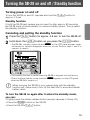
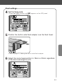
Attaching the SB-28 to the camera
When attaching the SB-28 to your camera, make sure both units are
turned off to avoid accidentally firing the flash.
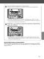
the SB-28's mounting foot locking wheel and slide the
1 Loosen
SB-28 into the camera’s accessory shoe.
2 Tighten the locking wheel.
With cameras equipped with a safety lock system, the mount pin is automatically
inserted into the locking hole in the camera’s accessory shoe to secure the SB-28.
Detaching the SB-28
• To detach the SB-28, loosen the mounting foot locking wheel all the
way. If the wheel doesn’t loosen easily, push the foot forward gently
14 in the direction of the white arrow and try loosening the wheel again.
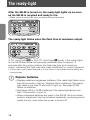
Turning the SB-28 on and off / Standby function
Turning power on and off
To turn the SB-28 on and off, depress and hold the = button for
approx. 0.5 sec.
Standby function
If both the SB-28 and camera are not used for after approx. 80 seconds,
the SB-28 shuts off automatically to conserve battery power. This is called
the standby function.
Canceling and setting the standby function
1 Press the = button for approx. 0.5 sec. to turn the SB-28 off.
2 Hold down the µ button as you press the = button.
—The SB-28’s standby mode indicator : on the LCD panel appears when
the function is set and disappears when it is not set. Perform steps 1 and 2 to
cancel it or reset it.
• The standby function is preset when the SB-28 is shipped from the factory.
(Check that the standby mode indicator : appears on the LCD panel
when the SB-28 is turned on.)
When carrying the SB-28 in your camera bag with the standby
function set, make sure to turn off the flash unit to avoid accidental
battery drain.
To turn the SB-28 on again after it enters the standby mode,
you can:
• Lightly press the shutter release button (except cameras in Group VII).
• Press the ~ button on the SB-28.
• Press the SB-28’s = button.
15
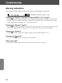
The ready-light
After the SB-28 is turned on, the ready-light lights up as soon
as the SB-28 is recycled and ready to fire.
—Make sure the ready-light lights up before taking the picture.
The ready-light blinks when the flash fires at maximum output.
In TTL Auto Flash t or Non-TTL Auto Flash ˙ mode, if the ready-lights
on the SB-28 and inside the camera’s viewfinder blink for approx. 3
seconds after the picture is taken, the flash has fired at its maximum
output, indicating that light may have been insufficient for correct exposure.
• In that case, use a wider aperture or move closer to the subject before taking any
more pictures.
Replace batteries.
• Replace alkaline-manganese batteries if the ready-light takes more
than 30 seconds to light up. Replace lithium batteries if the readylight takes more than 10 seconds to light up. See page 87-88,
Notes on batteries.
• Recharge NiCd or Ni-MH batteries if the ready-light takes more
than 10 seconds to come on.
• When exhausted batteries are used in the SB-28, the zoom-head
position adjustment may be activated repeatedly, producing sound
inside the unit, even when the power is turned off.
16
Test firing
You can perform simple test firing by pressing the ~ button to
ensure that the SB-28 is working properly.
1 Press the = button to turn the SB-28 on.
the ready-light comes on, press the ~ button to fire
2 After
the SB-28.
NOTE
If the SB-28 enters the standby mode, press the ~ button once
to turn the flash back on, then press the ~ button again to test-fire
the unit.
17
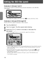
Setting the ISO film speed
Cameras in Groups I and II
The ISO film speed is automatically set and indicated on the SB-28’s
LCD panel.
• The usable film speed in TTL Auto Flash t mode is ISO 25 to 1000.
Cameras in Groups III through VII
Set the ISO film speed manually in this manner:
1 Turn the SB-28 off.
2 Turn it on again. The film speed starts blinking.
the { or } button to increase or decrease the
3 Press
film speed.
—Press the [ button to stop the film speed from blinking.
• The film speed indicator blinks during adjustment and stops after 8 seconds
unless the [ button is pressed. The last blinking number is the one
automatically set.
• The following ISO film speeds can be used in TTL Auto Flash t mode :
ISO 25 to 1000 for cameras in Groups III and IV, plus F-501/N2020 and
F-301/N2000 cameras.
ISO 25 to ISO 400 for cameras in Group VI, plus F-401s/N4004s and
F-401/N4004 cameras.
18
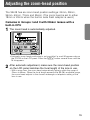
Adjusting the zoom-head position
The SB-28 has six zoom-head position settings: 24mm, 28mm,
35mm, 50mm, 70mm and 85mm. (The zoom head is set to either
18mm or 20mm when the built-in wide flash adapter is used.)
Cameras in Groups I and II with Nikkor lenses with a
built-in CPU
1 The zoom head is automatically adjusted.
• Automatic zoom-head positioning is not possible if a small M appears above
the ZOOM on the LCD panel. Press the ' button several times until the
M disappears.
automatic adjustment, make sure the zoom-head position
2 After
on the LCD panel matches the focal length of the lens in use.
—With a zoom lens, the zoom head automatically adjusts within the range of
24mm to 85mm. When the focal length exceeds the SB-28's available range,
the zoom-head adjusts to the closest wideangle or telephoto setting of the
lens in use.
19
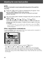
Adjusting the zoom-head position
NOTE
To cancel automatic zoom-head positioning and set the position
manually:
the ' and { buttons simultaneously for approx. 2 sec.
1 Press
until the small M above ZOOM starts blinking.
Then press the ' button and set the desired zoom-head
position manually.
zoom-head position indicator changes every time you press the
2 The
' button:
24mm
28mm
35mm
50mm
70mm
85mm
Once set manually, the zoom-head position is locked and does not
change even when the power is turned off and on again or the lens
is changed.
—To resume automatic zoom-head position adjustment, press the '
and { buttons simultaneously for approx. 2 sec. until the small M above
ZOOM disappears.
Other camera/lens combinations
Press the ' button and adjust the zoom-head position manually to
match the focal length of the lens in use.
• The indicator changes each time you press the ' button:
24mm
28mm
35mm
50mm
70mm
85mm
When set manually, a small M appears above the ZOOM on the LCD panel.
—When using a Zoom-Nikkor lens, set the zoom-head position on the SB-28 to
correspond to the shortest focal length of the lens (for example, select the 28mm
setting when using a Zoom-Nikkor 28-85mm lens). Then, the flash will cover all the
focal lengths.
20
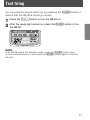
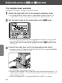
Setting the built-in wide flash adapter
The SB-28 comes with a wide flash adapter to increase the angle of
coverage to match an 18mm or 20mm lens.
out the wide flash adapter 1 and gently push it down into
1 Slide
place in front of the flash head 2.
• Because the bounce card comes out at the same time, return it 3 to its
original position inside the flash head.
• The zoom-head position indicator changes to 20mm and the indicator bars _
display the appropriate flash shooting distance range.
2 To change to 18mm, press the ' button once.
—The zoom-head position indicator toggles between 18mm and 20mm each
time you press the ' button.
• To replace the wide flash adapter, lift it up and slide it back into its original
place inside the flash head.
If the built-in wide flash adapter is broken off accidentally, it is
no longer possible to set 18 or 20mm.
In this case, press the ' and [ buttons simultaneously for
approx. 4 sec. until the zoom-head position indicator starts blinking,
making it possible to adjust the zoom-head automatically or manually to its
six basic settings (24, 28, 35, 50, 70, 85mm).
21
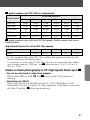
Selecting a flash mode
When the µ button on the back of the SB-28 is pressed, the flash
mode indicator sequences through these modes:
tØ
t
˙
Q
"
tø
Note that the LCD indications and available flash modes differ depending
on which Nikon camera and lens you are using.
The table below shows the auto flash mode recommended for use with
each camera group.
—Refer to the reference pages corresponding to your camera.
Camera group
Recommended auto flash mode
Reference
page
I
Automatic Balanced Fill-Flash with TTL Multi Sensor tØ
26–30
II
Matrix Balanced Fill-Flash tø
31–32
III
Matrix Balanced Fill-Flash t
33–34
IV
Matrix Balanced Fill-Flash t
35–37
V
Programmed TTL Auto Flash t
38–39
VI
Standard TTL Flash t
40–41
VII
Non-TTL Auto Flash ˙
42–43
• For available flash operations with the SB-28 and each camera group, refer to the
table on the fold-out page at the front of this manual.
22
Basic operation
Shooting in the auto flash mode
The SB-28 provides a variety of flash modes to cover virtually all
shooting situations. These modes range from TTL Auto Flash t
to Non-TTL Auto Flash ˙ and Manual Flash ƒ.
In this section, TTL and Non-TTL Auto Flash modes are explained.
TTL Auto Flash t :
If your camera is in group I to VI, refer to pages 24-25, t flash modes, to get the most
out of TTL automatic flash operations.
Non-TTL Auto Flash ˙ :
If your camera is in Group VII with no TTL Auto Flash t mode available, refer to pages
42-43, Non-TTL Auto Flash ˙ mode. This mode can also be used with cameras in all
groups.
t flash modes
Six flash operations are possible in the TTL Auto Flash mode:
flash modes
3D Multi-Sensor Balanced
Fill-Flash
Multi-Sensor Balanced
Fill-Flash
Automatic Balanced Fill-Flash
with TTL Multi Sensor**
Matrix Balanced
Fill-Flash
Automatic
Balanced
Fill-Flash*
Center-Weighted Fill-Flash/
Spot Fill-Flash
Programmed TTL
Auto Flash
Standard TTL Flash
* In combination with the camera’s exposure meter and TTL flash sensor, the shutter
speed, aperture, and SB-28’s flash output are automatically controlled to keep both
subject and background correctly exposed.
** 3D Multi-Sensor Balanced Fill-Flash and Multi-Sensor Balanced Fill-Flash are
generally referred to as Automatic Balanced Fill-Flash with TTL Multi Sensor.
3D Multi-Sensor Balanced Fill-Flash
(Applicable to F5, F100, F90X/N90s, F90-Series/N90, F80-Series/N80-Series, F70-Series/N70)
This mode automatically controls flash output to keep both subject and
background correctly exposed. The SB-28 fires a series of nearly invisible
preflashes, called Monitor Preflash. These preflashes are detected by the
TTL multi-sensor in Group I cameras and the data is then integrated with
distance information from D-type Nikkor lenses and other exposure data to
determine the optimal flash shooting distance range and flash output level
for balanced fill-flash exposure. This is especially effective for scenes that
include: (1) a mirror, white wall or other highly reflective surface or (2)
unwanted obstacles in front of the subject.
Multi-Sensor Balanced Fill-Flash
(Applicable to F5, F100, F90X/N90s, F90-Series/N90, F80-Series/N80-Series, F70-Series/N70)
This mode automatically controls flash output to keep both subject and
background correctly exposed when non-D-type AF or AI-P-type Nikkor
lenses are used. The SB-28 fires a series of nearly invisible Monitor
Preflashes, which are detected by the TTL multi-sensor to help determine
the best exposure for both subject and background. This method is most
effective for scenes that include: (1) a mirror, white wall, or other surface
highly reflective surface, or (2) a subject positioned against a distant
and/or plain background, such as an empty sky, clouds, etc.
24
Matrix Balanced Fill Flash
(Applicable to F4-Series, F65-Series/N65-Series, F60-Series/N60, F50-Series/N50,
F-801s/N8008s, F-801/N8008, F-601/N6006, F-601M/N6000, F-401x/N5005,
Pronea 600i/6i)
This mode automatically controls flash output to keep both subject and
background correctly exposed when D or non-D-type AF Nikkor lenses are
used. The camera's Matrix Metering System determines the correct
exposure based on the ambient light. Flash illumination brightens the main
foreground subject but does not overpower the background.
Center-Weighted/Spot Fill-Flash
(Applicable to F5, F4-Series, F100, F90X/N90s, F90-Series/N90, F70-Series/N70,
F60-Series/N60,F50-Series/N50, F-801s/N8008s, F-801/N8008, F-601/N6006, F601M/N6000, F-401x/N5005)
This mode operates with Center-Weighted or Spot metering. Centerweighted fill-flash measures the entire scene, but places emphasis on the
center area. Spot fill-flash reads a narrower central area or spot. Not all
Nikon AF cameras provide spot fill-flash.
Programmed TTL Auto Flash
(Applicable to F-501/N2020, F-401s/N4004s, F-401/N4004, F-301/N2000)
In this mode, you can perform auto flash operation with the lens set to its
minimum aperture (highest f-number). The camera automatically controls
the aperture according to the ISO film speed.
Standard TTL Flash
(Applicable to F5, F4-Series, F100, F90X/N90s, F90-Series/N90,
F80-Series/N80-Series, F70-Series/N70, F65-Series/N65-Series, F-801s/N8008s,
F-801/N8008, F-601/N6006, F-601M/N6000, F-501/N2020, F-401s/N4004s,
F-401/N4004, F-301/N2000, FM3A, FA, FE2, FG, Pronea 600i/6i, Nikonos V)
You manually select a flash output level so that the main subject is correctly
exposed regardless of the background brightness. This system is not
designed to automatically provide a balance between flash and ambient
light; it is limited to efficient operation in dim-light conditions and is not
recommended for use in very bright lighting conditions. This system does
not directly link the camera’s light meter and the SB-28’s TTL sensor.
25
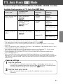
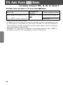
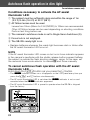
TTL Auto Flash t Mode
For cameras in Group I: F5, F100, F90X/N90s, F90-Series/N90, F80-Series/N80-Series, F70-Series/N70
Available flash operation in TTL Auto Flash t Mode
Camera’s
exposure
mode
Camera’s
metering
system*2
3D Multi-Sensor
Balanced Fill-Flash
tØ
Multi-Sensor
Balanced Fill-Flash
tØ
Desired
mode
Desired
metering
system
Desired
mode
Desired
metering
system
Center-Weighted
Fill-Flash/Spot FillFlash
tø
Aperture-priority
auto (A)
Center-Weighted
Metering
Lens in use
Available flash
operation*1
D- or G-type*3
Nikkor lenses
Non-D/G-type
AF Nikkor lenses/
AI-P lenses
Other Nikkor
lenses*4
Manual (M)
Spot Metering*2
* All of the above flash modes can be changed to Standard TTL Flash t.
*2 Only Standard TTL Flash is possible when the F5’s, F100’s or F80-Series/N80-Series’ Metering
System is set to Spot Metering.
*3 With a G-type Nikkor lens attached to F90X/N90s, F90-Series/N90, F70-Series/N70 cameras,
the A and M exposure modes cannot be used.
*4 With a non-CPU Nikkor lens attached to F80-Series/N80-Series cameras, Standard TTL Flash
can be performed. (Can only be used with exposure mode set to Manual) The camera’s
exposure meter cannot be used. Set and confirm the aperture using the lens aperture ring.
1
Monitor Preflash will not operate:
• If the flash head is tilted up or rotated from the horizontal/front position.
• When the camera’s flash sync mode is set to rear-curtain sync.
• When TTL Auto Flash (not 3D Multi-Sensor Balanced Fill-Flash or MultiSensor Balanced Fill-Flash) mode is selected. (In this case no Ø
indicator appears.)
• When a Nikkor lens without a built-in CPU is used.
Camera settings
Set the aperture.
1
—The method for setting the aperture differs, depending on the lens in use
and the selected exposure mode. (See page 29, Confirming flash
shooting distance range in TTL Auto Flash t Mode.)
2 Set the flash sync mode.
—Set the camera’s flash sync mode (if available) to front-curtain sync
(Normal).
26
Flash settings
3 Select the flash mode.
—Press the µ button until the desired auto flash mode appears on
the LCD panel.
tØ Automatic Balanced FillFlash with TTL Multi
Sensor
tø Center-Weighted/Spot FillFlash
t
Standard TTL Flash
4 Check the shooting distance.
A flash shooting distance range of
0.8 to 6m (2.6 to 20 ft) is shown.
• With the F5 camera’s Custom Setting, you can select 1/300 TTL High-Speed
Sync. In this case, you cannot confirm the shooting distance using the
indicator bars _ on the SB-28’s LCD panel. (See page 30 on Flash
shooting distance range in 1/300 TTL High-Speed Flash sync operation.)
for the ready-light to come on and make sure the subject
5 Wait
is in focus before taking the picture.
27
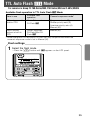
TTL Auto Flash t Mode
For cameras in Group I: F5, F100, F90X/N90s, F90-Series/N90, F80-Series/N80-Series, F70-Series/N70
The ready-light blinks when the flash fires at maximum
output.
Underexposure indicator
Amount of underexposure
• If the SB-28’s ready-light and the underexposure indicator blink for
approx. 3 seconds after shooting, the flash has fired at its maximum
output, indicating the light was insufficient for correct exposure. The
amount of underexposure (for example, –1.0 to –3.0) also appears on the
SB-28's LCD panel. To compensate, use a wider aperture or move closer
to the subject and reshoot.
• You can recall the amount of underexposure last shown on the LCD panel
by pressing the . button.
28
Confirming the flash shooting distance range in TTL
Auto Flash t Mode
Applicable to cameras in Groups I and II
The method for confirming the shooting distance differs, depending on the
lens in use and the selected exposure mode. Check the flash shooting
distance range as described below.
Flash shooting distance range
Aperture value
Nikkor lenses with a built-in CPU
• In Programmed auto (P, Ps) or Shutter-priority auto (S) mode:
(1) Set the lens to its minimum aperture (highest f-number) (except G-type
Nikkor lenses).
(2) Press the shutter release button halfway and check the shooting
distance range on the SB-28’s LCD panel.
• In Aperture-priority auto (A) or Manual (M) mode:
Check the indicator bars _ and the subject’s distance as you rotate the
camera’s command dial or lens aperture ring to determine the aperture
value.
Nikkor lenses without a built-in CPU
• In Aperture-priority auto (A) or Manual (M) mode only:
(1) While looking at the indicator bars _, press the { or } button to
change the aperture and bring the subject within the flash shooting
distance range.
(2) Note the aperture and set it on the lens.
29
TTL Auto Flash t Mode
For cameras in Group I: F5 only
Flash shooting distance range in 1/300 TTL High-Speed
Flash sync operation (F5 only)
In combination with the F5 camera, 1/300 High-Speed Flash Sync (with
Custom Setting; 1/250 sec. at normal setting) is possible. But the farthest
flash shooting distance cannot be read from the indicator bars _ on the
SB-28 in TTL Auto Flash t Mode.
In this case, use the guide number table and equation for calculating this
distance according to each zoom-head position.
Guide number (at ISO 100 for m/ft)
Zoom head position
Guide number
18mm 20mm 24mm 28mm 35mm 50mm 70mm 85mm
8/26
8/26
11/36
12/39
14/46
16/53
18/59
19/62
Guide number
D (farthest flash shooting distance) = ——————————
f/stop (aperture)
For example, when shooting with ISO 100 film, at a 35mm zoom-head position and
an aperture of f/5.6:
D = 14/5.6 = 2.5 (measured in meters)
D = 46/5.6 = 8.2 (measured in feet)
The farthest flash shooting distance is 2.5m (8.2ft). You can read the closest
shooting distance from the SB-28’s indicator bars _.
• For film speeds other than ISO 100, multiply the figures in the table above by the
factors shown below.
ISO film speed
Factor
30
25
50
200
400
800
x 0.5
x 0.71
x 1.4
x2
x 2.8
TTL Auto Flash t Mode
For cameras in Group II: F4-Series, F65-Series/N65-Series, F-801s/N8008s, F-801/N8008, Pronea 600i/6i
Available flash operation in TTL Auto Flash t Mode
Lens in use*1
Available flash
operation*2
Camera’s
exposure
mode
Camera’s
metering
system*3
Nikkor lenses with a
built-in CPU*4
Matrix Balanced
Fill-Flash
tø
Desired
mode*5
Matrix
Metering
Center-Weighted
Fill-Flash/
Spot Fill-Flash*6
tø
Desired
mode
CenterWeighted
Metering
Center-Weighted FillFlash/Spot Fill-Flash*6
tø
Aperture-priority
auto (A)
Nikkor lenses
without a built-in
CPU*7
Spot Metering*3
Center-Weighted
Metering
Manual (M)
Spot Metering*3
*1 Matrix Balanced Fill-Flash operation is possible with F4-Series camera when AI-S or AI-type
Nikkor lenses, Nikon Series E lenses, and lenses for the F3AF are used.
*2 The above flash modes can be changed to Standard TTL Flash t .
*3 Only Standard TTL Flash can be performed when the F4’s Metering System is set to Spot
Metering.
*4 With a G-type Nikkor lens attached to F4-Series, F-801s/N8008s, F-801/N8008 cameras, the A
and M exposure modes cannot be used.
*5 With F65-Series/N65-Series and Pronea 600i/6i cameras, only Standard TTL Flash can be
performed when the camera’s exposure mode is set to Manual (M).
*6 Center-Weighted Fill-Flash/Spot Fill-Flash is not possible with the F65-Series/N65-Series,
Pronea 600i/6i cameras.
*7 With a non-CPU Nikkor lens attached to F65-Series/N65-Series or Pronea 600i/6i cameras,
Standard TTL Flash can be performed. (Can only be used with exposure mode set to Manual)
The camera’s exposure meter cannot be used. Set and confirm the aperture using the lens
aperture ring.
Camera settings
Set the aperture.
1
—The method for setting the aperture differs, depending on the lens in
use and the selected exposure mode. (See page 29 on Confirming flash
shooting distance range in TTL Auto Flash t Mode.)
2 Set the flash sync mode.
—Set the camera’s flash sync mode (if available) to front-curtain sync
(Normal).
31
TTL Auto Flash t Mode
For cameras in Group II: F4-Series, F-801s/N8008s, F-801/ N8008, Pronea 600i/6i
Flash settings
3 Select the flash mode.
—Press the µ button until the desired auto flash mode indicator
appears on the LCD panel:
tø Matrix Balanced Fill Flash
and Center-Weighted
Fill Flash/Spot Fill-Flash
t
Standard TTL Flash
4 Check the shooting distance.
A flash shooting distance range
of 0.8 to 6m (2.6 to 20 ft) is shown.
for the ready-light to come on and make sure the subject
5 Wait
is in focus before taking the picture.
• If the ready-light blinks for approx. 3 seconds after shooting, this indicates
the light may have been insufficient for correct exposure. In this case, use
a wider aperture or move closer to the subject.
32
TTL Auto Flash t Mode
For cameras in Group III: F-601/N6006, F-601M/N6000
Available flash operation in TTL Auto Flash t Mode
Use the camera’s MODE button to select the flash mode.
Lens in use
Available flash
operation
Camera’s
exposure
mode
Camera’s
metering
system
Nikkor lenses with a
built-in CPU*1
Matrix Balanced
Fill-Flash t
Desired
mode
Matrix
Metering
Center-Weighted
Fill-Flash/Spot FillFlash t
Desired
mode
CenterWeighted
Metering,
Spot Metering*2
Nikkor lenses
without a built-in
CPU
Center-Weighted
Fill-Flash/Spot FillFlash t
Aperturepriority
auto (A),
Manual (M)
CenterWeighted
Metering,
Spot Metering*2
*1 G-type Nikkor lenses cannot be used with an F-601/N6006 camera. With a G-type Nikkor lens
attached to an F-601M/N6000 camera, the A and M exposure modes cannot be used.
*2 Spot Metering is not possible with the F-601M/N6000.
Camera settings
Set the aperture.
Nikkor lenses with a built-in CPU
1
• In Programmed auto (P, PM) or Shutter-priority auto (S) mode:
—Set the lens to its minimum aperture (highest f-number) (except G-type
Nikkor lenses).
• In Aperture-priority auto (A) or Manual (M) mode:
—While looking at the indicator bars _, press the { or } button to
change the aperture and bring the subject within the flash shooting
distance range. Then set the same aperture on the lens aperture ring.
Nikkor lenses without a built-in CPU
• In Aperture-priority auto (A) or Manual (M) mode only:
—While looking at the indicator bars _, press the { or } button to
change the aperture and bring the subject within the flash shooting
distance range. Then set the same aperture on the lens aperture ring.
2 Set the flash sync mode.
—Set camera’s flash sync mode (if available) to front-curtain sync
(Normal).
3 Select the flash mode on the camera.
33
TTL Auto Flash t Mode
For cameras in Group III: F-601/N6006, F-601M/N6000
Flash settings
Select the flash mode.
4
—Press the µ button until t appears on the LCD panel.
• Set your camera to the Matrix
Balanced Fill Flash or CenterWeighted Fill-Flash/Spot Fill-Flash
mode.
5 Check the shooting distance.
A flash shooting distance range
of 0.8 to 6m (2.6 to 20 ft) is shown.
Nikkor lenses with a built-in CPU
• In any exposure mode:
—Press the { or } button until the same aperture as displayed on the
camera’s LCD panel or in viewfinder is set on the SB-28’s LCD panel, then
confirm the flash shooting distance range.
Nikkor lenses without a built-in CPU
• In Aperture-priority auto (A) or Manual (M) mode only:
—Press the { or } button until the same aperture on the lens is set on the
SB-28’s LCD panel, then confirm the flash shooting distance range.
for the ready-light to come on and make sure the subject
6 Wait
is in focus before taking the picture.
• If the ready-light blinks for approx. 3
seconds after shooting, this indicates
the light may have been insufficient
for correct exposure. In this case,
use a wider aperture or move closer
to the subject.
34
TTL Auto Flash t Mode
For cameras in Group IV: F60-Series/N60, F50-Series/N50 and F-401x/N5005
Available flash operation in TTL Auto Flash t Mode
Lens in use
Available flash
operation
Nikkor lenses with a
built-in CPU
Matrix Balanced
Fill-Flash t
Programmed auto (P)
Shutter-priority auto (S)
Aperture-priority auto (A)
Manual (M)*
Nikkor lenses
without a built-in
CPU
Center-Weighted
Fill-Flash/Spot FillFlash t
Manual (M)
Camera’s exposure mode*
* Center-Weighted Fill-Flash/Spot Fill-Flash can only be performed when the
camera’s exposure mode is set to Manual (M).
Flash settings
1 Select the flash mode.
—Press the µ button until t appears on the LCD panel.
35
TTL Auto Flash t Mode
For cameras in Group IV: F60-Series/N60, F50-Series/N50 and F-401x/N5005
the shooting distance according to the lens in use and the
2 Check
exposure mode selected on the camera.
Flash shooting distance range
With Nikkor lenses with a built-in CPU
For F60-Series/N60 and F50-Series/N50 (In Programmed Auto (P) or
Shutter-Priority Auto (S) exposure mode)
With an F60-Series/N60 or F50-Series/N50 camera in the ADVANCED mode, set
the aperture appearing in the camera’s viewfinder on the SB-28’s LCD panel by
pressing the SB-28’s { or } button. With an F50-Series/N50 camera in the
SIMPLE mode, select the aperture from the table below and set the same
aperture on the SB-28’s LCD panel.
Lighting
conditions (at ISO100)
Sunny day
Aperture setting
on SB-28
Cloudy day or in
the shadows
f/8
f/5.6
Indoors
f/4
For F-401x/N5005 (In Programmed Auto (P) or Shutter-Priority Auto (S)
exposure mode)
Select the aperture from the table and set the same aperture on the SB-28’s
LCD panel by pressing the SB-28's { or } button. Then confirm the flash
shooting distance range.
Lighting
conditions:
(at ISO 100)
Aperture setting
on SB-28
Usable shutter
speed*
Strong backlighting
f/16
Sunny day
f/8
1/125 sec.
Cloudy day
or in the
shadows
f/5.6
Indoors
f/5.6
1/30 sec.
*In shutter-priority auto mode, the aperture is automatically selected by the camera.
36
For F60-Series/N60, F50-Series/N50 and F-401x/N5005 (in AperturePriority Auto (A) or Manual (M) mode)
Note the aperture set on the lens and set the same aperture on the
SB-28’s LCD panel by pressing the { or } button. Then confirm the
flash shooting distance range.
With Nikkor lenses without a built-in CPU
(for F60-Series/N60, F50-Series/N50 and F-401x/N5005)
Select the aperture on the lens and set the same aperture on the
SB-28’s LCD panel by pressing the SB-28's { or } button, then
confirm the flash shooting distance range.
for the ready-light to come on and make sure the subject is
3 Wait
in focus before taking the picture.
• If the ready-light blinks for approx. 3 seconds after shooting, this indicates the
light may have been insufficient for correct exposure. In this case, use a
wider aperture or move closer to the subject.
37
TTL Auto Flash t Mode
For cameras in Group V: F-501/N2020, F-401s/N4004s, F-401/N4004, F-301/N2000
Available flash operation in TTL Auto Flash t Mode
For F-501/N2020 and F-301/N2000
Lens in use
Available flash
operation
Nikkor lenses with a built-in CPU* Programmed
Nikkor lenses for F3AF
TTL Auto Flash
AI-S-type Nikkor lenses
t
AI-type Nikkor lenses
Standard TTL
Nikon Series E lenses
Flash t
Other Nikkor lenses
Standard TTL
Flash t
Camera’s exposure
mode
Programmed auto (P)
Aperture-priority auto (A)
Manual (M)
Aperture-priority auto (A)
Manual (M)
*G-type Nikkor lenses cannot be used.
For F-401s/N4004s and F-401/N4004
Lens in use
Available flash
operation
Camera’s exposure
mode
Nikkor lenses with a built-in CPU
Programmed
TTL Auto Flash
t
Programmed auto (P)
Standard TTL
Flash t
Aperture-priority auto (A)
Standard TTL
Flash t
Manual (M)
Other Nikkor lenses
Shutter-priority auto (S)
Manual (M)
Flash settings
1 Select the flash mode.
—Press the µ button until t appears on the LCD panel.
38
the aperture on the SB-28’s LCD panel, then confirm the
2 Set
flash shooting distance range.
Flash shooting distance range
Guide to determining aperture :
For F-501/N2020 and F-301/N2000 (in Programmed Auto (P) mode)
Select the aperture for the film in use from the table (or the aperture set by the
camera in aperture-priority auto (A) or manual (M) mode). Press the SB-28's { or }
button to set the corresponding aperture on the SB-28's LCD panel, then confirm the
flash shooting distance range.
ISO film speed
25
50
100
200
400
800
Aperture setting on SB-28
f/2.8
f/4
f/5.6
f/8
f/11
f/16
For F-401s/N4004s and F-401/N4004 (at ISO 100) (in ShutterPriority Auto (S) or Programmed Auto (P) exposure mode)
Select the aperture from the table (aperture set on the camera in aperture-priority auto
or manual mode) and set the same aperture on the SB-28’s LCD panel by pressing the
SB-28's { or } buttons, then check the flash shooting distance range.
Subject conditions
Aperture setting on SB-28
Usable shutter speed*
Strong backSunny day
lighting
f/16
f/8
1/125 sec.
Cloudy day
or in the
shadows
Indoors
f/5.6
f/5.6
1/30 sec.
*In shutter-priority auto mode, the aperture is automatically selected by the camera.
for the ready-light to come on and make sure the subject is
3 Wait
in focus before taking the picture.
• If the ready-light blinks for approx. 3 seconds after shooting, this indicates the light
may have been insufficient for correct exposure. In this case, use a wider aperture
or move closer to the subject.
39
TTL Auto Flash t Mode
For cameras in Group VI: FM3A, FA, FE2, FG, Nikonos V
Available flash operation in TTL Auto Flash t Mode
Lens in use
Available flash
operation
Camera’s exposure mode
Nikkor lenses with a built-in CPU*
Standard TTL Flash Aperture-priority auto (A)
and
t
Nikkor lenses without a built-in CPU
Manual (M)
*G-type Nikkor lenses cannot be used.
• In aperture-priority auto (A) mode, the shutter speed is automatically set
to 1/250 sec. for the FM3A, FA, FE2, and 1/90 sec. for the FG, Nikonos V.
When setting a shutter speed at a much slower speed, set the camera’s
exposure mode to Manual (M).
• Standard TTL Flash is not possible if the shutter speed is set to M250 or
B (bulb) for the FA, FE2, and M90 for the FG, Nikonos V.
40
Flash settings
1 Select the flash mode.
—Press the µ button until t appears on the LCD panel.
2 Check the shooting distance.
—Press the SB-28's { or } button until the aperture set on the lens is set on
the SB-28's LCD panel, then confirm the flash shooting distance range.
Flash shooting distance range
for the ready-light to come on and make sure the subject
3 Wait
is in focus before taking the picture.
• If the ready-light blinks for approx. 3 seconds after shooting, this indicates
the light may have been insufficient for correct exposure. In this case,
use a wider aperture or move closer to the subject.
41
Non-TTL Auto Flash ˙ Mode
For cameras in all groups
In Non-TTL Auto Flash shooting, the SB-28’s light output
automatically changes to match the flash-to-subject distance. The
light, however, is not measured through the lens, but is measured
by the light sensor on the front of the SB-28.
—The SB-28 can be used in Non-TTL Auto Flash mode with any Nikon camera/lens
combination at any ISO film speed.
—You can choose apertures from f/2 to f/16 at ISO 100.
Flash settings
1 Select the flash mode.
—Press the µ button until ˙ appears on the LCD panel.
2 Select the aperture.
—Press the [ button, then press the { or } button to change the
aperture, bringing the subject within the flash shooting distance range.
Flash shooting distance
Aperture value
42
Camera settings
3 Select the exposure mode.
—Set the camera’s exposure mode to Aperture-priority auto (A) or
Manual (M).
4 Set the aperture on the lens.
—Set the aperture that appears on the SB-28’s LCD panel on the lens.
• The subject will be overexposed if you set a larger aperture (smaller
f-number) on the camera than on the SB-28, and underexposed if you
set a smaller one (larger f-number).
5 Set the correct shutter speed.
—Set the camera to its highest flash sync shutter speed.
for the ready-light to come on and make sure the subject
6 Wait
is in focus before taking the picture.
• If the ready-light blinks for approx. 3 seconds after shooting, this indicates
the light may have been insufficient for correct exposure. In this case, use
a wider aperture or move closer to the subject.
43
44
Advanced operation
For handling difficult lighting situations or
expressing your ideas
In addition to convenient Auto Flash,
the SB-28 offers a host of other advanced operations
to match your creative ideas
or when unusual lighting situations are encountered.
Manual Flash ƒ Mode
For cameras in all groups
Manual flash photography is provided when shooting subjects in
which the correct exposure is difficult to obtain in the TTL or NonTTL Auto Flash Mode.
Flash settings
1 Select the flash mode.
—Press the µ button until ƒ appears on the LCD panel.
2 Adjust the flash output level.
—Press the { or } button to choose a flash output level.
Exposure compensation value
Flash output level
The indicator changes every time you press the } button:
1/1(0.0)
1/2(0.0)
1/2(-0.3)
1/2(-0.7)
1/4(0.0)
1/64(0.0)
%
The indicator changes every time you press the { button:
%
1/64(0.0)
1/64(+0.3)
1/64(+0.7)
1/32(0.0)
1/2(0.0)
1/1(0.0)
The numbers in parentheses ( ) represent the adjustable flash output
level in ±1/3 steps.
—The indicator bar ¡ on the LCD panel changes to match the shooting
distance at the flash output level set, and the corresponding exposure
compensation value is displayed on the LCD panel.
46
• To extend the flash shooting distance range, choose a flash output level
close to 1/1 or set the lens to a larger aperture (smaller f-number).
• % indicator appears only when used in combination with the SB-28 and
cameras in Group I (except F80-Series/N80-Series, F70-Series/N70). (See
page 49 on FP High-Speed Flash sync. % in Manual Flash ƒ mode.)
Camera settings
3 Select the exposure mode.
—Set the camera’s exposure mode to Aperture-priority auto (A) or
Manual (M).
4 Set the aperture.
—For cameras in Groups I and II with Nikkor lenses with a built-in CPU: Set
the aperture on the camera as you watch the indicator bar ¡ on the LCD
panel as it changes to match the shooting distance.
—For other camera/lens combinations: Press the { or } button to change
the aperture on the LCD panel. Then set the same aperture on the lens
aperture ring.
• You can calculate the correct shooting distance by using the guide
number equation. (See pages 56-57 on Guide Numbers for determining
correct aperture in Manual ƒ and Repeating " Flash mode.)
for the ready-light to come on and make sure the subject
5 Wait
is in focus before taking the picture.
47
Manual Flash ƒ Mode
For cameras in all groups
Synchronization in continuous shooting in Manual ƒ mode.
The SB-28 is able to recycle fast enough to synchronize with a motor-driven
camera firing continuously up to six frames per sec. at a 1/64 flash output
level. It is possible to take up to 40 flash pictures in rapid succession.
Number of continuous flashes at six frames per sec.
Optional
power
source
Flash output
Batteries Inside SB-28
( SB-28 only) All types
SD-7
AA-type alkalinemanganese
1/8
1/16
1/32
1/64
Up to 4
Up to 8
Up to 16
Up to 30
Up to 6
Up to 10
Up to 40
AA-type alkalinemanganese
SD-8
SD-8A*
AA-type NiCd
Up to 20
Up to 5
Up to 10
AA-type Ni-MH
Up to 30
Lithium
AA-type alkalinemanganese
SK-6
SK-6A*
AA-type NiCd
Up to 40
Up to 20 Up to 5
AA-type Ni-MH
Lithium battery
Up to 10
Up to 30 Up to 20
*Available in the European market only.
• SD-7 uses C-type alkaline-manganese batteries.
• Because the European version of the SB-28 comes with a different shaped
connector, Nikon DC Units SD-7, SD-8 and the Power Bracket Unit SK-6 are not
compatible.
• Fresh and same type batteries must be used in both the SB-28 and optional Nikon
DC Units SD-8/8A*, and Power Bracket Unit SK-6/6A*.
Allow the SB-28 to cool off for at least 10 minutes after the maximum
number of continuous firing shown in the table.
Flash mode and output
Max. number of continuous firings
t, ˙, " , and ƒ 1/1 and 1/2
15
ƒ 1/4, 1/8, 1/16, 1/32, 1/64
40
Even if the number of continuous firings is less than those listed
above, it’s a good idea to let the SB-28 cool off as often as possible
when using it in a warm environment.
48
FP High-Speed Flash sync % in Manual Flash ƒ mode
For F5, F100, F90X/N90s, F90-Series/N90
The SB-28 allows you to use faster shutter speeds for flash
synchronization. With FP High-Speed Flash sync %, the flash emits light
at an extremely rapid rate, while the shutter curtains travel to expose the
film. This enables you to use a faster shutter speed as well as a wider
aperture to achieve shallower depth of field to blur the background.
• Attach the SB-28 to the camera and turn on both the SB-28 and the camera, then
set the SB-28 to FP High-Speed Flash sync %.
Camera settings
Set the exposure mode to Manual (M).
1
2 Set the aperture.
—With Nikkor lenses with a built-in CPU: Rotate the command dial on the
camera or the lens aperture ring (for F90X/N90s, F90-Series/N90
cameras) as you watch the indicator bar ¡ on the LCD panel change to
match the shooting distance.
—With Nikkor lenses without a built-in CPU: Press the { or } button to
change the aperture on the LCD panel. Then set the same aperture on
the lens aperture ring.
3 Set the shutter speed.
—Set the shutter speed between 1/250 and 1/4000 sec.
• The guide number for FP High-Speed Flash sync % varies with the
selected shutter speed and is less than that for regular flash
synchronization. (See page 51 on % guide numbers.)
• In the % mode, when taking flash photographs with a shutter speed
slower than 1/250 sec., it is recommended to use normal flash operation
because the guide number is less in the % mode.
• If you set the SB-28’s flash mode to a mode other than Manual ƒ %
with your camera’s shutter speed set higher than 1/250 sec., the shutter
speed is automatically set to 1/250 sec.
49
Manual Flash ƒ Mode
For F5, F100, F90X/N90s, F90-Series/N90 only
Flash settings
4 Select the flash mode.
5 Set % on the LCD panel.
—Press the µ button until ƒ appears on the LCD panel.
—Press the { or } button until % appears on the LCD panel. The
indicator bar ¡ on the LCD panel changes to show the shooting
distance.
The indicator changes every time you press the } button:
1/1(0.0) 1/2(0.0) 1/2(-0.3) 1/2(-0.7) 1/4(0.0)
1/64(0.0)
The indicator changes every time you press the { button:
% 1/64(0.0) 1/64(+0.3) 1/64(+0.7) 1/32(0.0)
1/2(0.0)
%
1/1(0.0)
for the ready-light to come on and make sure the
6 Wait
subject is in focus before taking the picture.
• A small amount of underexposure may result in a more pleasing photograph
by shooting a subject which is further to the right by 1 or 2 steps from the
distance represented by the indicator bar ¡ on the LCD panel.
• If the flash-to-subject distance does not match the appropriate shooting
distance shown by the indicator bar ¡, choose a different setting for the
zoom-head position (smaller than the focal length of the lens in use) or
move closer to or farther away from the subject.
50
% guide numbers (at ISO 100; for meters/feet)
Zoom-head position
Shutter speed
24mm
28mm
35mm
50mm
70mm
85mm
1/250 sec.
14/46
15/50
17/56
20/65
23/74
24/77
1/500 sec.
10/33
11/36
12/39
14/46
16/52
17/56
1/1000 sec.
7/23
7.5/25
8.5/28
10/33
11/36
12/39
1/2000 sec.
5/16
5.3/17
6/20
7/23
8/26
8.5/28
1/4000 sec.
3.5/11
3.7/12
4.2/14
5/16
5.7/18
6/20
% guide numbers vary with the ISO film speed, shutter speed, and zoomhead position.
Adjustment factors for other ISO film speeds
ISO film speed
Factor
25
50
200
400
800
x 0.5
x 0.71
x 1.4
x2
x 2.8
• For film speeds other than ISO 100, multiply the guide numbers by the
factors shown in the above chart.
For example, for a film speed of ISO 400, with the zoom-head adjusted to 35mm,
and a shutter speed of 1/500 sec., the % guide number is 12 x 2 = 24 (m), or
39 x 2 = 78 (ft).
Notes on flash photography in FP High-Speed Flash sync %
• Do not use the built-in wide flash adapter.
When used, M20 or M18, ƒ and % blink on the LCD panel as a
warning.
• Detaching the SB-28
When you remove the SB-28 from the F5, F100, F90X/N90s or F90Series/N90, be sure to cancel FP flash operation. If the flash is removed
with the FP setting, % blinks as a warning.
51
Repeating Flash " Mode
For cameras in all groups
In the " mode, the SB-28 fires repeatedly during a single
exposure, creating stroboscopic multiple-exposure effects. This
mode is useful when shooting fast-moving subjects.
Flash settings
1 Select the flash mode.
—Press the µ button until ƒ " appear on the LCD panel.
the flash output level, the frequency (Hz), and the
2 Set
number of repeating flashes per frame.
• Referring to the table on page 53, set the flash output level, the
frequency, and the number of repeating flashes per frame separately.
—Press the [ button until the flash output level starts blinking, then
press the { or } button to set the desired flash output level. Finally,
press the [ button to stop the flash output level from blinking.
—Repeat the procedures above to set the frequency and the number of
repeating flashes per frame.
• The numbers blink during adjustment and stop after 8 seconds unless
the [ button is pressed. The non-blinking number is the one
automatically set.
Frequency (Hz)
Flash output level
Number of repeating flashes
per frame
52
NOTE
Frequency (Hz)
Flash output level
Number of repeating flashes
per frame
—In the example, at 1/8 flash output level, the flash will fire three times per
frame at a frequency of 4 flashes per second.
Maximum number of repeating flashes per frame
Flash output level
Frequency*
M1/8
M1/16
M1/32
M1/64
1-2 Hz
14
30
60
90
3 Hz
12
30
60
90
4 Hz
10
20
50
80
5 Hz
8
20
40
70
6 Hz
6
20
32
56
7 Hz
6
20
28
44
8 Hz
5
10
24
36
9 Hz
5
10
22
32
10 Hz
4
8
20
28
20-50 Hz
4
8
12
24
*Frequency (Hz) represents the number of flashes per second. The higher the number, the
shorter the flash firing interval.
53
Repeating Flash " Mode
For cameras in all groups
Camera settings
3 Set the exposure mode to Manual (M).
4 Set the aperture.
—For cameras in Groups I and II with Nikkor lenses with a built-in CPU:
Change the aperture on the camera as you watch the indicator bar ¡
on the LCD panel change to match the shooting distance.
—For other camera/lens combinations: Press the { or } button to
change the aperture on the LCD panel. Then set the same aperture on
the lens aperture ring.
The indicator bar ¡ shows a flash shooting distance in which the
correct exposure can be obtained with a single flash firing.
5 Set the shutter speed.
—Use the equation to determine the shutter speed.
Number of flashes per frame
Shutter speed = ————————————————
Frequency of flashes (Hz)
For example, if the number of flashes per frame is 10 and frequency is
5 Hz, divide 10 by 5 to get a shutter speed of 2 sec. or slower.
—Or you can set the shutter speed to B (bulb) to accommodate any
number of repeating flashes.
for the ready-light to come on and make sure the subject
6 Wait
is in focus before taking the picture.
—Press the ~ button to make sure the flash fires correctly as set.
• In the Repeating Flash Mode, use a tripod to prevent camera/flash shake.
Allow the SB-28 to cool off for at least 10 minutes after 10
sequences of repeating flash.
54
Exposure compensation in Repeating Flash Mode
The flash shooting distance calculated in step number 4 is the correct
exposure for the first flash in the sequence. Therefore, repeating flash at
this flash output level will result in overexposure of the overlapped images.
To prevent this, use a smaller aperture.
NOTE
Use fresh or fully charged batteries when performing repeating flash.
Allow enough time for the flash to recycle between each repeating flash.
55
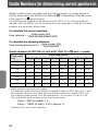
Guide Numbers for determining correct aperture in
Guide numbers help you determine a correct exposure or proper aperture
(f/stop) when using the SB-28 in the Manual ƒ or Repeating Flash " mode.
• See page 51 for % guide numbers.
The guide number represents the amount of light (ISO 100: for m/ft) generated by
the flash. With the SB-28, you can calculate a correct aperture by using the following
equation and the guide number table.
To calculate the correct aperture:
Guide number (GN)
f/stop (aperture) = ——————————————
Flash shooting distance (m/ft)
To calculate the shooting distance:
Guide number (GN)
Flash shooting distance (m/ft) = ——————————
f/stop (aperture)
Guide numbers (at ISO 100: for m/ft at 20。C/68。F) in ƒ and " modes
Zoom-head position
Flash output
level
18mm
20mm
24mm
28mm
1/1 (full)
18/59
35mm
50mm
70mm
85mm
20/66
30/98
32/105 36/118 42/138 48/157 50/164
1/2
12.7/42 14/46
21/69
22.5/74 25.5/84 30/98
34/112 36/118
1/4
9/30
10/33
15/49
16/53
21/69
24/79
25/82
1/8
6.4/21
7/23
10.5/35 11.3/37 12.7/42 15/49
17/56
18/59
1/16
4.5/15
5/16
7.5/25
1/32
3.2/10
3.5/11
5.3/17
5.7/19
6.4/21
7.5/25
8.5/28
9/30
1/64
2.3/8
2.5/8
3.8/13
4/13
4.5/15
5.3/17
6.0/20
6.3/21
8/26
18/59
9/30
10.5/35 12/39
12.7/42
• Guide number varies with film speed.
For example, when shooting a subject located 9m (approx. 30 ft) away at 1/1 (full)
flash output, with the zoom-head position at 35mm and a film speed of ISO 100,
first read the guide number from the table above. In this case, it is 36 (or 118).
Then divide the guide number by the shooting distance:
f/stop = 36/9 (in meters) = 4
f/stop = 118/30 (in feet) = 3.93 = approx. 4
Therefore f/4 is the correct aperture.
56
ƒ and " flash modes
Adjustment factors for other ISO film speeds
ISO film speed
Factor
25
50
200
400
800
1600
x 0.5
x 0.71
x 1.4
x2
x 2.8
x4
For film speeds other than ISO 100, multiply the guide numbers by the factors shown
in the above table.
For example, if the film speed in the previous example was ISO 400 rather than ISO
100, the guide number is 72 (36 x 2).
57
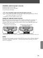
Bounce flash operation
Applicable to all camera groups
When taking pictures indoors, direct flash often causes harsh,
unattractive shadows on the subject or background. By bouncing
the light off the ceiling or walls, you can soften the shadows and
produce more natural-looking portraits.
With the SB-28's built-in bounce card, you can create a highlight in the
subject's eyes. (See page 61, Using the built-in bounce card.)
Bounce flash shooting using diffused light
Normal flash shooting using direct flash
Camera settings
1 Select the exposure mode.
2 Set the aperture.
—Set camera’s exposure mode to Aperture-priority auto (A) or Manual (M).
• With bounce flash, there is a 2 to 3 stop light loss or more, depending on
the height of the ceiling, when compared with normal flash operation.
Therefore, you should use the largest aperture (smaller f-number)
possible and bracket your exposures.
58
Flash settings
3 Select a flash mode.
—Press the µ button until t or ˙ appears on the LCD panel.
4 Tilt and/or rotate the flash head.
—Depress the flash head tilting/rotating lock release button and tilt the
flash head up at least 60° to bounce light off the ceiling.
• If the angle of the flash head is not far enough off axis from the subject,
uneven illumination will result from a combination of direct and bounced
flash.
• In color photography, select white or highly reflective surfaces to bounce
light off of. Otherwise, your pictures will come out with an unnatural color
cast similar to that of the reflecting surface.
59
Bounce flash operation
Applicable to all camera groups
Flash head tilting and rotating angle
For bouncing light off the walls or when the camera is held vertically, the
SB-28’s flash head tilts up to 90° and rotates horizontally 180° (to the left) and
90° (to the right). Always set the flash head at a click stop.
• When the flash head is tilted up or rotated from the horizontal/front position,
the shooting range indicator bars _ on the LCD panel disappear and the
SB-28’s Monitor Preflash does not operate.
• The shooting range indicator bars _ blink when the flash head is tilted
down to the –7° position. This position is used when shooting subjects
1.5m (approx. 5 ft) or closer.
for the ready-light to come on and make sure the subject is
5 Wait
in focus before taking the picture.
• If the ready-light blinks for approx. 3 seconds after shooting, the flash fired at
its maximum output, indicating the light may have been insufficient for correct
exposure. In that case, use a wider aperture or move closer to the subject.
• In bounce flash operation, no shooting range indicator bars _ appear.
Therefore, you should check the distance between the flash head and the
bounce surface, between the bounce surface and the subject, and the angle
of tilt or rotation of flash head, then bracket your exposures by ±1 or 2 stops.
60
Using the built-in bounce card
In bounce flash photography, you can create a highlight in the subject’s
eyes by using the SB-28's built-in bounce card. This white card reflects a
small amount of light directly back to the subject, opening up the shadows
and making the eyes look more vibrant.
1 Pull out the wide flash adapter.
holding the bounce card, slide the wide flash adapter back
2 While
into place inside the flash head.
• After sliding the wide flash adapter back into place, pull out the bounce card
gently as far as it goes. Be careful not to force the bounce card.
3 Set the flash head as shown and take pictures.
• After use, don’t forget to slide the bounce card back into its original position
inside the flash head.
61
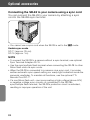
Close-up flash operation in TTL Auto Flash t Mode
When shooting subjects closer than 0.6m (2 ft), use your SB-28 off
camera and utilize its built-in wide flash adapter.
the SB-28 to your camera using the optional TTL
1 Connect
Remote Cord SC-17.
• For F5 cameras with a High-Magnification Finder DW-30 or DW-31, use the
optional TTL Remote Cord SC-24.
• For F4 cameras with a High-Magnification Finder DW-20 or DW-21, use the
optional TTL Remote Cord SC-24.
Camera settings
the exposure mode to Aperture-priority auto (A)
2 Set
or Manual (M).
—For cameras with VARI-PROGRAM or SIMPLE mode, close-up flash
photography is easy by setting the camera to the Close-Up mode.
3 Set the aperture.
—Calculate the aperture (f/stop) by using this equation and table.
coefficient
f/stop = ————————————
flash-to-subject distance
ISO film speed and coefficient
ISO film speed
100 or lower
125–400
500 or higher
Coefficient*
4 (13)
8 (26)
11 (36)
*Numbers in parentheses ( ) represent coefficients in feet.
For example, with a subject 0.5m (1.6ft) away using ISO 100 film and the wide flash
adapter in place, the suggested aperture is:
4
f/stop = —— (in meters) = 8,
0.5
13
f/stop = —— (in feet) = approx. 8
1.6
Therefore, you should use f/8 or a smaller aperture, such as f/11.
62
Flash settings
4 Set the flash mode.
—Press the µ button until t appears on the LCD panel.
5 Position the built-in wide flash adapter over the flash head.
• Refer to page 21, Setting the built-in wide flash adapter.
the zoom-head position to 18mm or 20mm regardless
6 Adjust
of the lens focal length in use.
63
Close-up flash operation in TTL Auto Flash t Mode
the SB-28 off axis, making sure the subject will
7 Move
receive sufficient illumination.
• In 3D Multi-Sensor Balanced Fill-Flash mode with cameras in Group I, you
may not be able to obtain correct exposure because distance information
from the lens (D-type Nikkor) is used. In this case, position the camera
and SB-28 at equal distances from the subject.
for the ready-light to come on and make sure the subject
8 Wait
is in focus before taking the picture.
• If the ready-light blinks for approx. 3 seconds after shooting, this indicates
the light may have been insufficient for correct exposure. In this case, use
a wider aperture or move closer to the subject.
• Correct exposure cannot be obtained if the subject is predominantly black
or white or contains a highly reflective surface. In that case, make
exposure compensation according to the shooting conditions.
(See pages 71-75, Exposure compensation in flash photography,
to ensure correct exposure.)
64
Multiple flash operation in t and ƒ flash modes
To eliminate harsh, directional shadows produced by a single flash
unit or to add additional illumination to the background, you can
attach additional Nikon Speedlights in series.
Flash shooting with more than one unit
Flash shooting with one flash unit
For multiple flash operation with the SB-28, both TTL Auto Flash t and
Manual Flash ƒ modes are possible.
• Multiple flash operation in TTL Auto Flash t mode is possible with cameras in
Groups I through VI and F3-Series cameras. Multiple flash operation in Manual
Flash ƒ mode is possible with cameras in all groups.
• For applicable flash units and accessories, see pages 68-69, System chart for TTL
multiple flash.
• In multiple flash operation, first decide which will be the main unit and which the
secondary unit(s). To eliminate shadows, adjust the lighting ratio so that
illumination from the main unit is greater than that from the secondary unit(s).
Notes on multiple flash operation
• In multiple flash operation, if the electric current in the synchro circuit exceeds a
certain level, you may not be able to take a second shot after the first. In this case,
turn each of the flash units off once or disconnect the SB-28 unit from the camera.
This resets the circuits so you can resume shooting.
• In multiple flash operation, take care that the combined total of the coefficients
(numbers shown in parentheses below) for all flash units used at the same time
does not exceed 20 at 20°C (68°F), or 13 at 40°C (104°F).
Speedlight coefficients
SB-50DX (1) SB-29 (1)
SB-28/28DX (1)
SB-26 (1)
SB-25 (1)
SB-24 (1)
SB-22s (1)
SB-22 (6)
SB-21 (4)
SB-17 (4)
SB-16 (4)
SB-15 (4)
SB-11 (1)
SB-140 (1)
Coefficient numbers in parentheses are in
SB-27
SB-23
SB-20
SB-14
(1)
(4)
(9)
(1)
units of 70µA.
65
Multiple flash operation in t and ƒ flash modes
TTL multiple flash operation
Cameras in Groups I through VI and F3-Series
1 Attach the main flash unit to the camera’s accessory shoe.
• To use the SB-28 off-camera, refer to pages 68-69, System chart for TTL
multiple flash, for the correct type of optional TTL Remote Cord to use.
2 Set the flash mode of the master flash unit to t mode.
• To obtain the correct exposure with the SB-28 when used as the main flash
and set to 3D Multi-Sensor Balanced Fill-Flash, cancel Monitor Preflash on
the main flash unit by pressing the µ button until t appears on the
LCD panel.
3 Connect the main flash unit to the secondary flash unit(s).
—Use one or more TTL Remote Cords SC-18 or SC-19 to connect the SB-28 to
the secondary flash unit(s) in series.
• Turn off all flash units before connecting.
• Use Multi-Flash Adapter AS-10 when using more than three flash units for TTL
multiple flash operation, or if the secondary flash units are not equipped with
multiple flash terminals.
• Use Tripod Adapter AS-11 to attach the SB-16A or SB-17 to a tripod.
66
4 Set the flash mode on all the flash units to t.
• Turn on all flash units and make sure their Standby functions are canceled.
the same procedures as in normal TTL Auto Flash
5 Follow
t mode.
• When all flash units are set to Manual flash ƒ mode, Manual multiple flash
operation is performed.
TTL multiple flash operation using the Wireless
Slave Flash Controller SU-4 (optional)
• TTL multiple flash operation is possible by using the camera’s built-in
Speedlight or a Speedlight mounted on the camera’s hot shoe as the
master flash unit, and one or more Speedlights mounted on the Wireless
Slave Flash Controller SU-4s as slave flash units. The SU-4’s built-in light
sensor not only detects when the master flash unit fires to trigger the slave
flash unit, but also controls the flash duration of the slave flash unit in sync
with the master flash unit.
• Manual multiple flash operation is also possible by setting the flash mode
selector to manual (M).
• These Nikon Speedlights are usable:
• SB-29, SB-28/28DX, SB-27, SB-26, SB-25, SB-24, SB-23, SB-22s, SB-22,
SB-20, SB-18, SB-16B, SB-15
• For more information, refer to the instruction manual provided with the SU-4.
SU-4
67
Multiple flash operation in t and ƒ flash modes
System chart for TTL multiple flash
(For cameras in Groups I through VI, plus F3-Series cameras)
• SB-11, SB-14, SB-140, and SB-21B Speedlights cannot be used with the
F-401/N4004 or F-401s/N4004s as either main or secondary units.
Main flash unit
Group I
SB-21B
F5 (with DA-30/DP-30)
F100
F90X/N90s
F90-Series/N90
F80-Series/N80-Series
F70-Series/N70
F5 (with DW-30/DW-31)
SB-11
SC-23
SC-24
SB-14
SB-140
A
A
Group II
SB-15 SB-16B
F4-Series
(with DW-20/DW-21)
A
F4-Series (DA-20/DP-20)
F65-Series/N65-Series
F-801s/N8008s
F-801/N8008
Pronea 600i/6i
SB-20 SB-22 SB-22s SB-23 SB-50DX
A
SB-29
SB-24 SB-25 SB-26
Group III
F-601/N6006 , F-601M/N6000
SB-28/28DX
SB-27
SC-17
Group IV
SB-21A
F60-Series/N60
F50-Series/N50
F-401X/N5005
SB-16A
Group V
SB-17
A
A
F-501/N2020, F-401s/
N4004s, F-401/N4004
F-301/N2000
Group VI
A
A
FM3A, FA
FE2
FG
A
A
Nikonos V
Group VII
F3-Series
68
V-type Syns
Cord
SC-14
AS-17
Items marked A on page 68 are
connected to item A on page 69.
Secondary flash unit
B
SB-16B SB-24 SB-25 SB-26 SB-28/28DX
SB-29
AS-10
B
SB-11
SB-15 SB-16B
SB-21B
SC-23
SB-14
SB-140
B
B
A
SC-18(1.5m)
SC-19(3m)
AS-10
SC-18
SC-19
SB-20 SB-22 SB-22s SB-24 SB-25 SB-26
SB-28/28DX
SB-27
B
SB-29
B
AS-10
SB-16A
AS-11
SC-18
SC-19
B
SB-17
AS-11
Using SC-18 or SC-19,
up to five flash units can
be used for multiple
flash photography, at a
total cable length of 10m
(33 ft.).
69
Multiple flash operation in t and ƒ flash modes
Manual multiple flash operation (For cameras in all groups)
• For speedlights which can serve as secondary flash units, see the
System chart for TTL multiple flash on pages 68–69.
the SB-28 to the sync terminal of the secondary flash
1 Connect
unit(s) using a cord.
Usable optional remote cords:
Use the sync terminals for connecting the SB-28 with other flash units
via the Sync Cord SC-11/SC-15, or TTL Multi-Flash Sync Cord
SC-18/SC-19.
2 Set the flash mode of all the flash units to Manual ƒ.
the zoom-head position and the flash-to-subject distance of
3 Set
the main flash unit and secondary unit(s).
• First set the zoom-head position and the flash-to-subject shooting distance of
the main flash unit, then on the secondary unit(s).
• To calculate the maximum number of flash units that can be connected, see
page 65.
4 Follow the same procedure as in normal Manual flash ƒ mode.
• For applicable guide numbers in Manual ƒ mode for each flash output level
at each zoom-head position, see pages 56-57, Guide Numbers for
determining correct aperture in ƒ and " modes.
70
Exposure compensation in flash photography
For cameras in all groups
In the TTL Auto Flash t or non-TTL Auto Flash ˙ mode, some plus
compensation may be necessary when the background includes a mirror,
white wall or other highly reflective surface. Likewise, some minus
compensation may be required when the background is dark or includes
subjects of low reflectivity.
You can also make exposure compensation to create flash photographs
which are somewhat brighter or darker to match the subject or your
creative preferences.
Exposure compensation methods can be divided into five categories. The
flash output level is automatically compensated in category 1, and
manually compensated by the user in the categories 2 to 5. But this may
vary depending on which camera you are using.
1 Automatic exposure compensation in TTL Auto Flash t mode
In 3D multi-sensor balanced fill-flash, Multi-sensor balanced fill-flash, and Centerweighted/Spot fill-flash operations, the flash output is automatically balanced to
keep both subject and background correctly exposed. To cancel automatic
exposure compensation, change the flash mode to Standard TTL Flash.
2 Intentional exposure compensation of the SB-28’s flash output in
TTL Auto Flash t mode
The SB-28’s flash output level can be compensated without affecting the
background exposure. (See page 72)
3 Intentional exposure compensation of the SB-28’s flash output and
the background in TTL Auto Flash t mode
Use your camera’s exposure compensation control button or dial to make
exposure compensation to both foreground and background. (See page 74)
4 Intentional exposure compensation of the main subject in Non-TTL
Auto Flash ˙ mode
Set a different aperture on the camera than that set on the SB-28 to make the
foreground subject lighter or darker. (See page 75)
5 Intentional exposure compensation of the main subject in Manual
ƒ mode
Intentionally set a different aperture on the camera than that set on the SB-28 or
change the flash output level. (See page 75)
Intentional exposure compensation described in categories 2 to 5 in TTL Auto
Flash t, Non-TTL Auto ˙ and Manual ƒ modes is explained on the following
pages.
71
Exposure compensation in flash photography
For cameras in all groups
Flash exposure compensation in TTL Auto Flash t mode
For cameras in Groups I through III when making exposure
compensation to the SB-28’s flash output
In the t mode, only the SB-28’s flash output can be compensated
without affecting the background exposure.
• Cameras with EV compensation capability allow you to make exposure
compensation on either the SB-28 or the camera (or both). If you use
both controls, exposure is modified by the sum total of both exposure
compensation values and will affect the background exposure.
Although the SB-28's LCD panel does not display the amount of
compensation set on the camera, the shooting range indicator bars_
still automatically change to match the exposure compensation.
NOTE
With cameras in Group III, make exposure compensation on the camera.
The amount of compensation set on the camera does not appear on the
SB-28’s LCD panel.
Flash settings
1 Press the µ button until t appears on the LCD panel.
the [ button until ¿ appears on the LCD panel
2 Press
and the exposure compensation value starts blinking.
72
3 Set the desired exposure compensation.
—Press the { or } button to increase or decrease the compensation.
• Exposure compensation is possible in 1/3 steps from –3.0 to +1.0 EV.
• The shooting range indicator bars _ automatically change according to
the amount of exposure compensation.
the
button to make the exposure compensation
4 Press
value stop blinking.
[
• The exposure compensation value blinks during adjustment and stops
after 8 seconds unless an adjustment is made. The last blinking number
is the one automatically set.
Canceling exposure compensation
Flash exposure compensation cannot be canceled by turning the SB-28
off. To cancel, reset the exposure compensation to 0.0 following the steps
outlined above.
73
Exposure compensation in flash photography
For cameras in all groups
Flash exposure compensation in TTL Auto Flash t mode
For cameras in Groups I through VI (when making exposure
compensation to the SB-28’s flash output and the background)
Use your camera's EV compensation control to make exposure
compensation. In this mode, flash output is automatically controlled to keep
both subject and background correctly exposed.
• For more details, refer to your camera's instruction manual.
The SB-28's LCD panel does not display the amount of compensation set on the
camera.
• With cameras in Groups I and II, the shooting range indicator bars _ automatically
change according to the amount of exposure compensation. For cameras other
than those in Groups I and II, use this chart as a guide in obtaining the correct
flash shooting distance range.
Exposure compensation values possible with various film speeds
Exposure compensation value
Film speed
+2
+1
0
–1
–2
—
—
25
50
100
ISO 50
—
25
50
100
200
ISO 100
25
50
100
200
400
ISO 25
ISO 200
50
100
200
400
800
ISO 400
100
200
400
800
—
ISO 800/1000
200
400
800
—
—
For example, with ISO 100 film, if you want to make an exposure compensation of +2
steps on the camera, set the film speed on the SB-28’s LCD panel to ISO 25, then
check the flash shooting distance range.
• For cameras in Groups I through VI, exposure compensation in the TTL Auto Flash
t mode is not possible when the film speed exceeds those listed above. In this
case, set the flash mode to Non-TTL Auto Flash ˙ or Manual Flash ƒ mode.
74
Flash exposure compensation in Non-TTL Auto
Flash ˙ mode
In this mode, if you don’t set the same aperture on the lens as that set on
the SB-28, you cannot obtain the correct exposure. Therefore, to make
exposure compensation, vary the aperture set on the camera while
retaining the aperture set on the SB-28.
• Read the flash shooting distance range as shown on the SB-28 without changing
the aperture set on the SB-28.
Flash exposure compensation in Manual Flash ƒ mode
In this mode, you can obtain the correct exposure by balancing three
factors: flash output level, flash-to-subject distance, and aperture.
You can calculate a correct aperture and flash shooting distance range by
using the guide number equations on page 56.
—First set the exposure indicated by the camera, then (1) use a different aperture on
the camera than that on the SB-28, or (2) select an output setting ranging from full
output (1/1) to one sixty-fourth (1/64).
For example, the subject will be overexposed
if you use a larger (smaller f-number)
aperture on the camera than that set on the
SB-28 or choose a higher flash output level
setting, and underexposed if you do the
opposite.
• Although the indicator bar ¡ on the SB-28’s LCD panel changes as you
change the flash output level, go ahead and shoot anyway.
75
Red-eye reduction control
For cameras in Group I (except F5), F65-Series/N65-Series and Pronea 600i/6i
When photographing people or animals in dim light using flash, the
subject's eyes may come out bright red in color pictures or white in
black and white pictures. This phenomenon is known as red-eye.
To prevent this, cameras in Group I (except the F5) as well as the
Pronea 600i/6i feature red-eye reduction control.
• You cannot set red-eye reduction on the SB-28 directly. For more information, refer
to your camera’s instruction manual.
• When red-eye reduction is set on your camera, the SB-28’s red-eye reduction LED
lights up for approx. 1 sec. before the flash fires to close down the iris of the
subject’s eyes.
Setting your camera to red-eye reduction
After setting your camera to red-eye reduction, check the SB-28's LCD
panel to make sure @ appears.
76
Rear-curtain flash sync
Cameras in Groups I through III featuring a rear-curtain flash sync mode
(F5, F100, F90X/N90s, F90-Series/N90, F80-Series/N80-Series, F70-Series/N70,
F65-Series/N65-Series, F-601/N6006 and Pronea 600i/6i cameras only)
In normal flash synchronization, the SB-28 fires at the beginning of the
exposure just after the front shutter curtain opens. When shooting fastmoving subjects at slower shutter speeds, this usually results in
unnatural-looking pictures where the subject frozen by the flash
appears behind or within the blurred movement.
In rear-curtain flash sync, the flash fires at the end of the exposure, just
before the rear curtain closes, creating a picture in which the frozen
subject is in front of the blurred action.
• Because the SB-28 does not have its own rear-curtain control, only those
cameras with a rear-curtain flash sync mode can perform this function by
setting it on the camera.
Rear-curtain flash sync (rear)
Front-curtain flash sync (normal)
• No rear-curtain flash sync indicator appears on the SB-28’s LCD panel even when
this mode is set on the camera.
• In multiple flash setups, the main flash unit can be set to either front-curtain or rearcurtain flash sync. The secondary units, however, cannot be set to rear-curtain
flash sync.
77
Rear-curtain flash sync
Cameras in Groups I through III featuring a rear-curtain flash sync mode
Flash settings
1 Select the flash mode.
—Press the µ button until the desired mode t, ˙, or ƒ appears on
the LCD panel.
• In Manual ƒ mode when either FP High-Speed Flash sync % or Repeating
" Flash is selected, rear-curtain flash sync cannot be performed.
Camera settings
2 Set the flash sync mode to rear-curtain sync.
3 Set the exposure mode.
—Set the camera’s exposure mode to Shutter-priority auto (S) or Manual (M).
• Although rear-curtain flash sync is possible in Programmed auto (P) or
Aperture-priority auto (A) mode, it is not recommended because you
cannot intentionally adjust the shutter speed.
4 Set the shutter speed.
• The slower the shutter speed you select, the more effective the results
will be.
• Use of a tripod is recommended.
the shooting distance. Wait
5 Check
for the ready-light to come on and
make sure the subject is in focus
before taking the picture.
• In t, or ˙ mode, if the ready-light
blinks for approx. 3 seconds after
shooting, this indicates the light may
have been insufficient for correct
exposure. In this case, use a wider
aperture or move closer to the subject.
78
Additional information
Reference section
In this section, information on
troubleshooting and optional accessories is presented.
Following that are tips on Speedlight care, notes on batteries,
with the SB-28’s specifications coming
at the end of the manual.
Checking the correct exposure
For cameras in all groups
In Non-TTL Auto Flash ˙ mode, you can determine whether the
subject will receive the correct exposure by test firing the SB-28
before actually taking pictures.
the camera’s exposure mode to Aperture-priority auto (A)
1 Set
or Manual (M).
the SB-28’s µ button until ˙ appears on the
2 Press
LCD panel.
3 Set the same aperture on both the SB-28 and the camera.
4 Check that the SB-28’s ready-light is on.
on the subject and check the shooting range indicator
5 Focus
bars _ to make sure it’s within range.
6 Press the ~ button to fire the flash.
If the ready-light blinks for approx. 3 seconds after shooting, this
indicates the light may have been insufficient for correct exposure. In
this case, use a wider aperture or move closer to the subject.
NOTE
To determine if the exposure will be correct in TTL Auto Flash t mode,
press the µ button to change the flash mode to the Non-TTL Auto
Flash ˙ mode. Set the same aperture on the SB-28’s LCD panel as in the
t mode, then perform test firing. If the ready-light blinks for approx. 3
seconds after shooting, the light will be insufficient for correct exposure in
the t mode as well.
80
Autofocus flash operation in dim light
For autofocus cameras only
When the light is too dim for normal autofocus operation, the
SB-28’s AF assist illuminator LED automatically turns on when set to
illuminate dark subjects when the shutter release button is
pressed halfway.
• Take care not to block the AF assist illuminator LED while shooting.
• The AF assist illuminator LED turns off as soon as the subject is in focus.
• The AF assist illuminator LED will not light up with an F5, F100,
F80-Series/N80-Series or F65-Series/N65-Series camera unless the
camera’s central focus area is selected.
81
Autofocus flash operation in dim light
For autofocus cameras only
Conditions necessary to activate the AF assist
illuminator LED:
1 The subject must be sufficiently dark and within the range of 1m
(3.3 ft) to 8m (16.4 ft) at 20°C (68°F).
2 AF Nikkor lenses must be used.
Lenses from 24mm (35mm for F-501/N2020) to 105mm are recommended.
Other AF Nikkor lenses can be used depending on shooting conditions.
Perform test firing before use.
3 The camera's autofocus mode is set to Single Servo Autofocus (S).
4 Focus lock is not employed.
5 The SB-28’s ready-light is on.
• Replace batteries whenever the ready-light becomes dark or blinks after
the AF assist illuminator LED turns on.
NOTE
If the AF assist illuminator LED comes on but no in-focus indicator appears
in the camera's viewfinder with the shutter release button pressed halfway,
the subject is outside the flash shooting distance range. In this case, set
the camera’s focus mode selector to manual ƒ and focus manually.
To cancel autofocus flash operation with the AF assist
illuminator LED
Hold down the µ button as you press the } button.
—The ; indicator comes on or disappears on the LCD panel every time you
press the µ and } buttons simultaneously.
—The AF assist illumination LED is set when the ; indicator is not on and
canceled when the ; indicator appeared.
—The AF assist illumination LED is preset to operate when the SB-28 is shipped
from the factory.
82
Optional accessories
Accessories for multiple flash
Sync Cord SC-11 and SC-15
Sync Cords SC-11 and SC-15 are handy when you want to use the SB-28
off-camera or for use with cameras without accessory shoes. These cords
also allow you to perform Multiple Flash photography in the Manual ƒ
mode. The SC-11 is approx. 25 cm (9.8 in.) long and the SC-15 is approx.
1m (3.2 ft) long.
TTL Remote Cord SC-17 and SC-24
The TTL Remote Cord SC-17 provides TTL Auto Flash operation when the
SB-28 is used off-camera. Its flash shoe comes with one tripod socket and
two TTL multiple flash terminals. The TTL Remote Cord SC-24 is for use
with F5 cameras mounted with a High-Magnification Finder DW-30 or
DW-31 or F4 cameras with a High-Magnification Finder DW-20 or DW-21.
Both the SC-17 and SC-24 are approx. 1.5m (4.9 ft) long.
TTL Multi-Flash Sync Cord SC-18 and SC-19
Multi-Flash Sync Cords SC-18 or SC-19 are useful for connecting the SB-28
to the multiple flash terminal of the SC-17 or AS-10 for TTL multiple flash
operation. The SC-18 is approx. 1.5 m (4.9 ft) long, and the SC-19 is
approx. 3 m (9.8 ft) long.
TTL Multi-Flash Adapter AS-10
Use Multi-Flash Adapter AS-10 when connecting more than three flash
units together for TTL multiple flash operation, or if the secondary flash
units are not equipped with multiple flash terminals. The AS-10 comes with
one tripod socket and three TTL multiple flash terminals.
Sync Terminal Adapter AS-15
The Sync Terminal Adapter AS-15 is necessary when connecting the SB-28
to cameras not having a sync terminal.
Wireless Slave Flash Controller SU-4
Useful for multiple flash photography, the SU-4 features a built-in, movable
light sensor and an accessory shoe for attachment of a slave Speedlight.
The SU-4’s light sensor not only triggers the slave unit to fire in unison with
the master flash, but controls the flash duration of the slave unit in sync
with the master unit to provide TTL, non-TTL, or Manual operation.
TTL Flash Unit Coupler AS-17 for F3-Series cameras
Dedicated adapter for F3-Series cameras providing TTL flash operation
with Nikon Speedlights such as SB-29 and SB-28 featuring ISO-type
mounting foot (not designed for F3).
83
Optional accessories
Connecting the SB-28 to your camera using a sync cord
You can connect the SB-28 to your camera by attaching a sync
cord to the SB-28’s sync terminal.
• You cannot use a sync cord when the SB-28 is set to the t mode.
Usable sync cords
SC-11 (approx. 25 cm)
SC-15 (approx. 1m)
NOTE
• To connect the SB-28 to a camera without a sync terminal, use optional
Sync Terminal Adapter AS-15.
• Use the sync/multiple flash terminal when connecting the SB-28 to other
Nikon flash units via sync cords.
• When the SB-28 is connected to a camera via a sync cord, it provides
neither automatic sync speed setting nor ready-light indication inside the
camera’s viewfinder. To maintain all functions, use the optional TTL
Remote Cord SC-17.
• If a non-Nikon flash unit—one incorporating a high-voltage (above 50V)
or negative voltage sync circuits—is connected to the SB-28’s
sync/multiple flash terminal, the SB-28’s protection circuit is activated,
resulting in improper operation of the unit.
84
Available external power sources
External power source SD-7
External power source SD-8/8A*
Power Bracket SK-6/6A*
Use only Nikon-approved external power sources
Using external power sources other than those specified by Nikon
may cause damage to the SB-28.
* Available in the European market only.
Using an external power source
Nikon’s external power source DC Units increase the number of
flash firings and provide faster recycling time. (See page 93.)
To use a DC Unit, connect its power cord to the SB-28's external
power source terminal.
External power source terminal
External power source terminal
(for European market)
• Even when a DC Unit is used, the SB-28 still requires batteries inside the flash unit.
NOTE
Because the European version of the SB-28 comes with a different shaped
connector, Nikon DC Units SD-7, SD-8 and the Power Bracket Unit SK-6
are not compatible.
85
Tips on Speedlight care
Avoid physical shocks
Do not drop the SB-28 or hit it against a hard surface as this may damage
its precision mechanisms.
Never disassemble the SB-28
Never attempt to disassemble or repair the SB-28 yourself. The SB-28
contains high-voltage circuitry which can cause electric shock.
Keep the SB-28 away from water
The SB-28 is not waterproof and therefore should not be exposed to rain or
saltwater. If water gets inside the SB-28, corrosion may occur, resulting in
high repair costs.
Cleaning
Use a blower brush to remove dirt and dust from the SB-28 and clean it
with a soft, clean cloth. Never use commercial cleaners containing thinner,
benzene, or alcohol as they could damage its plastic parts.
Maintenance
When storing the SB-28 for two weeks or longer, remove the batteries to
prevent battery leakage. Also once a month, insert fresh batteries and fire
the unit several times to reform its capacitor and keep the SB-28 in top
working order.
Storage
Store the SB-28 in a cool, dry place to prevent mold and mildew. Also keep
it away from chemicals such as camphor or naphthalene. Avoid exposing
the SB-28 to magnetic waves from TVs or radios and never store it the
truck or glove compartment of a vehicle during the summer.
86
Notes on batteries
WARNING
• Keep batteries out of the reach of children. If a battery is
accidentally swallowed, call a doctor immediately.
Notes on handling batteries
• Do not expose batteries to excessive heat. Never store them in the truck
or glove compartment of a vehicle during the summer or place them near
a fire or hot surface. Even hot, direct sunlight may cause them to
explode.
• When loading batteries, make sure the SB-28 is turned off, then follow the
+ and – symbols inside the battery chamber.
• If the SB-28 is not used for more than two weeks, remove the batteries
and store them in a dry place at 20°C (68°F) or below.
• Battery power tends to weaken as the temperature drops. It also weakens
after heavy use, recovering gradually after a short break. Power gradually
decreases when batteries are not used for a long time. Check battery
power before use; replace batteries with a new set before they are
completely exhausted.
• Battery performance may differ with each brand, due to modification in
specifications or improvement in performance.
Four AA-type alkaline-manganese, lithium, or rechargeable
NiCd or Nickel-Metal Hydride (Ni-MH) batteries are required to
power the SB-28.
• For fast recycling times: NiCd batteries are recommended followed by (2)
Ni-MH, (3) alkaline-manganese, and (4) lithium batteries.
• For increasing the number of flashes per battery set: at normal
temperatures, lithium batteries are recommended followed by (2) alkalinemanganese, (3) Ni-MH, and (4) NiCd batteries; at low temperatures,
lithium batteries are recommended followed by (2) Ni-MH, (3) alkalinemanganese, and (4) NiCd batteries.
• Ni-MH batteries feature approx. the same battery power as 1000mAh
NiCd batteries.
• 1000mAh NiCd batteries have approx. 1.4 times the power capacity of
700mAh NiCd batteries.
87
Notes on batteries
• Lithium batteries have approx. 1.1 to 1.2 times the power capacity of
alkaline-manganese batteries.
• Lithium batteries feature greater efficiency at low temperatures when
compared with alkaline-manganese batteries. Lithium batteries boast
consistent performance in terms of recycling times and number of
flashes, regardless temperature changes.
• NiCd batteries boast a constant recycling time regardless of temperature
changes when compared with other types of batteries. Recommended for
use in temperatures as low as 0°C (32°F).
• Ni-MH batteries feature a constant recycling time but a little longer
recycling time at low temperatures when compared with NiCd batteries.
However, Ni-MH batteries maintain their efficiency regarding the number
of flashes regardless of temperature changes.
Notes on using alkaline-manganese and lithium batteries
• Non-rechargeable batteries such as alkaline-manganese and lithium
batteries should not be charged in a battery charger as they may
explode.
• Lithium batteries incorporate internal safety switches. When the battery
becomes hot, its safety circuit is activated, cutting off power. This often
occurs when the SB-28 is operated in the repeating flash mode. The flash
ready-light will not light up after firing approx. 24 exposures. However,
battery power will recover when the temperature goes back to normal.
Notes on using rechargeable NiCd and Ni-MH batteries
• When recharging batteries, be sure to use the battery charger specified
by the battery maker and read the instructions thoroughly.
Recharging should be done in temperatures from 10° to 30°C (50° to
86°F).
• Do not recharge NiCd or Ni-MH batteries with their terminals reversed in
the charger or before the batteries have cooled off sufficiently.
• Overcharging and excessive use may shorten battery life. Do not
overcharge and be sure to turn the SB-28 off when not in use.
• Because flash consumes a large amount of battery power, rechargeable
batteries may not operate properly before reaching the end of their stated
life-span or the number of charging/discharging as specified by the
battery manufacturer.
• If NiCd or Ni-MH batteries do not last as long as they should after being
fully charged, they are approaching the end of their life. Replace them
with a new set.
88
Troubleshooting
Camera
Group
All
camera
groups
Cause
No J indicator
appears.
• Batteries are not correctly
installed.
12
• Battery power is weak.
16
Ready-light blinks
for approx. 3 sec.
after shooting.
Group I
Group II
Ref.
page
Warning indicator
• Standby function is set and operating.
15
Flash fired at full output but light
may have been insufficient.
16
Power turns off.
Batteries are exhausted.
—
No indicator bars
_ appear.
SB-28’s flash head is tilted or
rotated from the horizontal/front
position.
13
Indicator bars _
blink.
Flash head is tilted down -7°.
13
Zoom-head position
indicator blinks.
The ' and [ buttons are
pressed simultaneously for approx. 4 sec.
21
Small M above
ZOOM blinks.
Zoom-head position is locked.
20
No tØ indicators
light up.
• A Nikkor lens other than one
having built-in CPU is mounted.
26
• Flash mode is set to t.
26
• F5’s or F100's Metering System is
set to Spot Metering
26
Ready-light and ÷ blink
after picture is taken.
Light was insufficient for correct
exposure.
28
Q % indicators
and small M above
the ZOOM as well as18
or 20 blink.
Built-in wide flash adapter is used in
FP High-Speed Flash sync.
51
% blinks.
SB-28 is removed with % setting.
51
No t ø indicators
light up.
• A Nikkor lens without a built-in
CPU is mounted.
• Flash mode is set to t.
31
• F4’s Metering System is not set to
Spot Metering.
31
31
NOTE
The SB-28 incorporates a microcomputer to control flash operations.
In rare cases, the SB-28 may not work properly even after fresh batteries
are properly installed. If this happens, replace the batteries with the
SB-28's power turned on.
89
Troubleshooting
Warning indications
The flash ready-light in the camera's viewfinder will blink:
S
0
F90X/N90s viewfinder display is shown.
Cameras in Groups I (except F70-Series/N70), II, III, V and VI.
—in the t mode, when you press the shutter release button halfway, to warn that
the SB-28 has not been securely mounted on the camera or that the flash output
may have been insufficient for correct exposure.
Cameras in Groups V and VI
—in the t mode, to indicate that the ISO rating of the film in use is higher than the
ISO set on the SB-28's LCD panel, (or lower in the case of the FA camera).
Cameras in Group VI
—in the t mode, when the shutter speed is set to M90, M250, or B.
Cameras in Group VII
—to warn that t flash shooting is not possible.
FM3A, New FM2
—when the shutter speed set is faster than the flash sync speed.
90
Specifications
Electronic
construction
Automatic Insulated Gate Bipolar Transistor (IGBT) and
series circuitry.
Guide number
(ISO 100, m/ft)
Flash
output
level
Zoom-head position
18mm 20mm 24mm 28mm 35mm 50mm 70mm 85mm
1/1 (full) 18/59
20/66
30/98
32/105 36/118 42/138 48/157 50/164
1/2
12.7/42 14/46 21/69
22.5/74 25.5/84 30/98
34/112 36/118
1/4
9/30
16/53
21/69
24/79
25/82
1/8
6.4/21 7/23
10.5/35 11.3/37 12.7/42 15/49
17/56
18/59
1/16
4.5/15 5/16
7.5/25 8/26
10.5/35 12/39
12.7/42
10/33
15/49
18/59
9/30
1/32
3.2/10 3.5/11 5.3/17 5.7/19 6.4/21 7.5/25 8.5/28 9/30
1/64
2.3/8
2.5/8
3.8/13 4/13
4.5/15 5.3/17 6.0/20 6.3/21
• See page 51 for details on guide numbers in FP HighSpeed Sync Flash and see also page 30 for details on
guide numbers in 1/300 TTL High-Speed Sync Flash.
Angle of
coverage
(Variable in 6 steps, plus 2-steps with built-in wide flash
adapter)
Flash head in horizontal/front position
Angle of coverage
Zoom-head position
Vertical
Horizontal
18mm (with built-in
wide flash adapter in
place)
90°
102°
20mm (with built-in
wide flash adapter
in place)
85°
98°
24mm
60°
78°
28mm
53°
70°
35mm
45°
60°
50mm
34°
46°
70mm
26°
36°
85mm
23°
31°
91
Specifications
Flash duration
(approx.)
1/840 sec.
1/1100 sec.
1/2300 sec.
1/4800 sec.
1/9100 sec.
1/19000 sec.
1/28000 sec.
Bounce
capability
Flash head tilts down to –7° or up to 90° with click-stops at
–7°, 45°, 60°, 75°, 90°; flash head rotates horizontally 180° to
the left with click-stops at 30°, 60°, 90°, 120°, 150°, 180° and
90° to the right with click stops at 30°, 60°, 90°
ON/OFF
button
Press the = button for approx. 0.5 sec. to turn the SB28 on or off. When the SB-28 is not used for approx. 80 sec.
the SB-28 automatically turns itself off to conserve battery
power. To turn the SB-28 back on, press the = button.
Flash
exposure
control
@
@
@
@
@
@
@
1/1 (full) output
1/2 outut
1/4 outut
1/8 output
1/16 output
1/32 output
1/64 output
Selected by µ button Available flash operation
tØ
tø
t
˙
Non-TTL Auto Flash
ƒ
• Manual Flash
• Flash output setting (7 steps):1/1,1/2, 1/4, 1/8,
1/16, 1/32, 1/64 (in increments of ±1/3 steps
• % High-Speed Sync Flash (for cameras in
Group I [except F70-Series/N70])
ƒ"
92
• Automatic Balanced Fill-Flash with TTL Multi
Sensor with Nikkor lenses with built-in CPU (for
cameras in Group I only) with Monitor Preflash
• Matrix Balanced Fill-Flash or CenterWeighted
Fill-Flash/ Spot Fill-Flash (for cameras in
Groups I through IV. The ø indicator appears
when used with cameras in Groups I and II only.)
• Standard TTL Flash (for cameras in Groups I
through VI)
• 1/300 TTL High-Speed Flash (for F5 only)
Repeating Flash
Rear-curtain sync flash
Setting is possible in t, ˙, or Q mode on
cameras featuring rear-curtain sync flash mode by
setting camera’s flash sync mode to rear-curtain sync.
Red-eye reduction
Setting is possible on cameras having red-eye
reduction or red-eye reduction in slow-sync.
(When set, @ indicator appears in the LCD panel.)
Power source
Four AA-type alkaline-manganese (1.5V), lithium (1.5V), NiCd
(rechargeable) (1.2V), or Ni-MH (rechargeable) (1.2V)
penlight batteries.
Optional
external
power
sources
• DC Unit SD-7; uses six C-type alkaline-manganese
batteries
• DC Unit SD-8/8A; uses six AA-type alkaline-manganese
batteries
• Power Bracket Unit (SK-6/6A); uses four AA-type alkalinemanganese batteries
(The SD-7, SD-8 and SK-6 not compatible with European version of
the SB-28.)
Min. recycling
Battery type required time* (approx.)
External
power
source SD-7**
External
power
source
SD-8/
8A***
Power
Bracket
SK-6/
6A***
C-type alkalinemanganese (x6)
2.5 sec.
AA-type alkalinemanganese (x6)
3.5 sec.
AA-type NiCd
(700 mAh) (x6)
AA-type NiCd
(1000 mAh) (x6)
2 sec.
AA-type Ni-MH (x6)
AA-type lithium (x6)
AA-type Alkalinemanganese (x4)
AA-type NiCd
(700mAh) (x4)
AA-type NiCd
(1000mAh) (x4)
AA-type Ni-MH(x4)
AA-type lithium (x4)
Min. number of flashes/
recycling time (approx.)
200 times/6 sec.
400 times/6-10 sec.
450 times/6-30 sec.
100 times/3.5-5 sec.
200 times/3.5-9 sec.
350 times/6-30 sec.
150 times/2-30 sec.
200 times/2-30 sec.
2.5 sec.
3.5 sec.
4 sec.
200 times/2.5-30 sec
350 times/3.5-30 sec.
250 times/4-30 sec.
2.5 sec.
100 times/2.5-30 sec.
140 times/2.5-30 sec.
3.0 sec.
4.5 sec.
140 times/3.0-30 sec.
300 times/4.5-30 sec.
* With fresh batteries
** With AA-type alkaline-manganese in the SB-28
***With same type of batteries in both the external power
source and the SB-28
• Above data may vary depending on the performance or
type of batteries.
93
Specifications
Number of
flashes and
recycling
times at full
output (with
batteries
installed in
the SB-28)
Batteries
4 AA-type alkalinemanganese
Min. recycling
time (approx.)
Min. number of flashes/
recycling time (approx.)
6.5 sec.
150/6.5-30 sec.
4 AA-type NiCd (700 mAh)
60/4-30 sec.
4 AA-type NiCd (1000 mAh) 4 sec.
90/4-30 sec.
4 AA-type Ni-MH
100/4-30 sec.
4 AA-type lithium
7.5 sec.
200/8-30 sec.
Note: Data measured with fresh batteries, but without using AF assist
LED, zoom-head position adjustment, or LCD panel illumination.
Red-eye
reduction
The red-eye reduction LED lights up for approx. 1 sec.
before the flash fires. This function is set on the camera.
Applicable to cameras in Group I (except F5) and Pronea
600i/6i.
AF assist
illumination
Automatically fires LED beam toward subject when
performing autofocus in dim light or in the dark with Nikon AF
cameras. Can be canceled.
Ready-light
• Lights up when SB-28 is recycled and ready to fire.
• Blinks for 3 seconds when flash fires at its maximum
output, indicating light may have been insufficient (in TTL
Auto Flash t and ˙ mode only).
FLASH button
• Performs test firing for correct exposure detection in ˙
mode or test firing in " mode. Can turn the SB-28 on
again after the unit enters standby mode.
Built-in wide
flash adapter
Allows the SB-28 to be used with 18mm or 20mm lenses.
Safety lock
system
With cameras equipped with a safety lock system, the mount
pin is automatically inserted into the locking hole in the
camera’s accessory shoe to secure the SB-28.
LCD panel
illuminator
Turns on and off every time the . button is pressed.
Illumination lasts approx. 16 seconds.
Flash
shooting
distance scale
Distance scale on the LCD panel can be set to either meters
(m) or feet (ft) by pressing the . and = buttons
simultaneously with SB-28 turned off.
94
Other
features
External power source terminal, TTL multiple flash terminal,
and sync/multiple flash terminal.
Dimensions
(W x H x D)
Approx. 69 x 128 x 90mm (2.7 x 5 x 3.6 in.)
Weight (without
batteries)
Approx. 320g (11.3 oz.)
Accessories
supplied
Soft Case SS-28, External power source terminal cap
All performance data are for normal-temperature operation (20°C/68°F)
Specifications and design are subject to change without notice.
Usable aperture/flash shooting distance ranges
in TTL Auto t and Non-TTL Auto ˙ flash modes
ISO film speed
1600*1 800*2 400
2.8
2
1.4
4
2.8
2
5.6
4
2.8
8
5.6
4
11
8
5.6
16 11
8
22 16 11
32 22 16
32 22
32
200
1.4
2
2.8
4
5.6
8
11
16
22
32
100
50
1.4
2
2.8
4
5.6
8
11
16
22
32
1.4
2
2.8
4
5.6
8
11
16
22
Shooting distance range (in meters)
25 18mm 20mm 24mm 28mm 35mm 50mm 70mm 85mm
2.3–20 2.5–20 3.8–20 4.0–20 4.5–20 5.3–20 6.0–20 6.3–20
1.6–18 1.8–20 2.7–20 2.9–20 3.2–20 3.8–20 4.3–20 4.5–20
1.2–12 1.3–14 1.9–20 2.0–20 2.3–20 2.7–20 3.0–20 3.2–20
0.8–9.0 0.9–10 1.4–15 1.5–16 1.6–18 1.9–20 2.2–20 2.2–20
1.4 0.6–6.3 0.7–7.0 1.0–10 1.0–11 1.2–12 1.4–14 1.5–16 1.6–17
2 0.6–4.5 0.6–5.0 0.7–7.5 0.7–8.0 0.8–9.0 1.0–10 1.1–12 1.1–12
2.8 0.6–3.1 0.6–3.5 0.6–5.3 0.6–5.6 0.7–6.3 0.7–7.4 0.8–8.4 0.8–8.8
4 0.6–2.2 0.6–2.5 0.6–3.7 0.6–4.0 0.6–4.5 0.6–5.2 0.6–6.0 0.6–6.2
5.6 0.6–1.5 0.6–1.7 0.6–2.6 0.6–2.8 0.6–3.1 0.6–3.7 0.6–4.2 0.6–4.4
8 0.6–1.1 0.6–1.2 0.6–1.8 0.6–2.0 0.6–2.2 0.6–2.6 0.6–3.0 0.6–3.1
11 0.6–0.7 0.6–0.8 0.6–1.3 0.6–1.4 0.6–1.5 0.6–1.8 0.6–2.1 0.6–2.2
16
0.6 0.6–0.9 0.6–1.0 0.6–1.1 0.6–1.3 0.6–1.5 0.6–1.5
: Programmed TTL Auto Flash with Nikon F-501/N2020, F-401s/N4004s, F-401/N4004 and
F-301/N2000. (ISO 25 to ISO 400 for F-401s/N4004s, F-401/N4004)
: Non-TTL Auto Flash mode
*1: TTL Auto Flash t operation is not possible at this film speed.
*2: TTL Auto Flash t is possible for cameras in Groups1to 4 and F-501/N2020 and F-301/N2000.
For ISO 1000, use an aperture 1/3 of an f/stop smaller than the aperture for ISO 1600.
• Usable apertures in the TTL Auto Flash t mode are f/1.4 to f/32, and the usable shooting distance
range is 0.6 to 20m.
95
Specifications
ISO film speed
1600*1 800*2 400
2.8
2
1.4
4
2.8
2
5.6
4
2.8
8
5.6
4
11
8
5.6
16 11
8
22 16 11
32 22 16
32 22
32
200
1.4
2
2.8
4
5.6
8
11
16
22
32
100
50
1.4
2
2.8
4
5.6
8
11
16
22
32
1.4
2
2.8
4
5.6
8
11
16
22
Shooting distance range (in feet)
25 18mm 20mm 24mm 28mm 35mm 50mm 70mm 85mm
7.4–66 8.2–66 13–66 14–66 15–66 18–66 20–66 21–66
5.3–59 5.8–65 8.7–66 9.3–66 11–66 13–66 14–66 15–66
3.7–41 4.1–46 6.2–66 6.6–66 7.4–66 8.7–66 9.9–66 11–66
2.6–29 2.9–32 4.4–49 4.7–52 5.2–59 6.1–66 7.0–66 7.2–66
1.4 2.0-20 2.1–23 3.1–34 3.3–37 3.7–41 4.3–48 4.9–55 5.1–57
2 2.0–14 2.0–16 2.2–24 2.4–26 2.6–29 3.0–34 3.5–39 3.6–41
2.8 2.0–10 2.0–11 2.0–17 2.0–18 2.0–20 2.2–24 2.5–27 2.6–28
4 2.0–7.3 2.0–8.2 2.0–12 2.0–13 2.0–14 2.0–17 2.0–19 2.0–20
5.6 2.0–5.2 2.0–5.7 2.0–8.6 2.0–9.2 2.0–10 2.0–12 2.0–13 2.0–14
8 2.0–3.6 2.0–4.1 2.0–6.1 2.0–6.5 2.0–7.3 2.0–8.6 2.0–9.8 2.0–10
11 2.0–2.6 2.0–2.8 2.0–4.3 2.0–4.6 2.0–5.2 2.0–6.0 2.0–6.9 2.0–7.2
16
2.0 2.0–2.0 2.0–3.0 2.0–3.2 2.0–3.6 2.0–4.3 2.0–4.9 2.0–5.1
: Programmed TTL Auto Flash with Nikon F-501/N2020, F-401s/N4004s, F-401/N4004 and
F-301/N2000. (ISO 25 to ISO 400 for F-401s/N4004s, F-401/N4004)
: Non-TTL Auto Flash mode
*1: TTL Auto Flash t operation is not possible at this film speed.
*2: TTL Auto Flash t is possible for cameras in Groups1to 4 and F-501/N2020 and F-301/N2000.
For ISO 1000, use an aperture 1/3 of an f/stop smaller than the aperture for ISO 1600.
• Usable apertures in the TTL Auto Flash t mode are f/1.4 to f/32, and the usable shooting distance
range is 2.0 to 66 ft.
96
No reproduction in any form of this manual, in whole
or in part (except for brief quotation in critical
articles or reviews), may be made without written
authorization from NIKON CORPORATION.
FUJI BLDG., 2-3, MARUNOUCHI 3-CHOME,
CHIYODA-KU, TOKYO 100-8331, JAPAN
Printed in Japan T2B0201603 (S904) 11