1
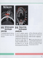
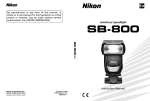
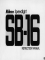
Nikon Speedlight
INSTRUCTION MANUAL
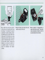
-NOMENCLATURE------------
Wide-Flash Adapter SW-7
Main flash head
® Main flash unit
(J) Light
sensor
® nn .nn/~ln,oo'" knob
2
Zoom scale
@Shooling mode indicator LEOs
@TTL multiple flash terminal
3
CONTENTS------------NOMENCLATURE . . . . .. .. . . .. . . . . . . . . . . . . . . .. 2rv 3
ATTENTION!. .. . ......... .... . ... . .. .... . .. . . .... . 5
FOREWORD .. . . . . . ........ .. . ......... . ...... ... 6
BASIC OPERATION . . .... . .... . ......... ... .. 7rv19
CONTROLS IN DETAIL .. . . . . . . ........... . ... 20rv47
Flash Unit Couplers AS-8 and AS-9 .. .... . .... 20
Synchronization Speed ... . ..... . .. .. . ........ 21
Zoom Head ....... . ..... . ..... . ... . . . . . ..... . 22
Shooting Mode Selector ... . ... . .. .. .. . ... 23rv 24
TTL (through -the-lens automatic operation) . ... .... 23
A (non-TTL automatic operation) . .. .... . .. . .... . . 23
M (manual operation) .. . . . . ..... . .............. 23
MD (synchronization with motor drive) .. . . . . ....... 24
Exposure Calculator Dial. . . .. ... ... . ..... 24rv 35
Set the film speed . . .. .. .. . .... . ... . ... ... . .. .. 24
Set t he zoom setting knob ...... . ........ . . . . .. . 25
Determine the exposure . .. . ... . ... .. .... . .. 25rv 32
Exposure compensation .... . .. .. . .. .. .. . . .. 33rv35
Ready-light ... ... . . . . . . ................. 36rv 41
Warn ing functions . ....... .. . . . ... . ... . ... . 37 ~ 41
Open-Flash Button . . .. .. . .. . ...... . .. . .. 42rv 43
Tilting/Rotating Flash Head . . .... . .. .. . ..... . 44
Secondary Flash Head .... .. .... . . . . ...... . .. 45
Wide-Flash Adapter SW-7 .... .. . ....... .. .. . . 46
TTL Multiple Flash Terminal .. ... . . .... . ..... . 47
Sync/Multiple Flash Terminal . . . .. . . .... .. . ... 47
4
PHOTOGRAPHIC TECHNIQUES ........... . . . 48rv62
Synchro-Sunlight Fill-In Flash
Photography ..... .. .. .. .. . ............ 48rv53
In the manual mode . . ....... . .. .. . . ... . .... . . . 50
In the TTL-automatic mode ...... . . . . . . . . .. . ... . 51
In the non-TTL automatic mode . ............ .. ... 51
Synchronization with slow shutter speeds .. . .. . 52rv53
Diffusing the light . . . . ....... .. .. . . . .. .. 54rv 57
Bounce flash photography .. . . . . ...... . ..... 54rv 56
Using a diffuser ... .... . ..... ....... . . . .. . . ... 57
Multiple Flash Photography . ..... . . ..... . 58rv62
TTL multiple flash photography .. . .. . . . ...... 59rv61
Manual multiple flash photography ............... . 62
ACCESSORIES . . .... . ..... .. .... ... .... .. . . 63rv65
Sync Cords SC-10, 11, and 15 .. . . .......... .. 63
TTL Remote Cord SC-14
. .. . .. . .. ... .... 63
TTL Remote Cord SC-17 .......... ... . ...... . 63
TTL Multi-Flash Sync Cords
SC-18 and SC-19 .......................... 64
TTL Multi-Flash Adaptor AS-10 .. . .. ... ..... . . 64
Flash Tripod Adaptor AS-11 . .. . .. . ..... . ..... 64
Flash Unit Couplers AS-1, 4, 5, 6, and 7 . . .. ... 64
Soft Flash Unit Case SS-16 .. ..... . .. . ....... 65
"RED EyE" . . .... ... .. . . . . ... ......... ... ....... 65
TIPS ON SPEEDlIGHT CARE ... . .. ........ . . .. 66rv67
OPTIMUM BATTERY PERFORMANCE .. .. . . ... . . .. . 68
SPECIFICATIONS ....... . ........ . .... .. . . . . 69rv 70
ATTENTIONI-------------The Nikon Speedlight S8-16 consists of two parts : the
main flash unit and the flash unit coupler having the
mounting foot. Depending on which type is attached , the
flash unit is identified as the Speedlight S8 -16A or S8-168.
The S8-16A's Flash Unit Coupler AS-B· has a special
mounting foot for the accessory shoe of Nikon F3 series
camera, while the S8-168's Flash Unit Coupler AS-9 features a standard ISO-type mounting foot.
As shown in the table, the S8-16A and S8-168 can be
mounted on any type of Nikon camera either directly
or with the use of another Nikon Flash Unit Coupler.
Usable shooting modes, however, are limited according
to the combination of the flash unit and camera. Please
reconfirm that the flash unit you purchased is suitable for
your camera, referring to the following table .
Usable shooting mode
Flash unit·
58-16A
(with AS-S)
58-168
(wlthAS-9)
Mounting
Camera
TTL
A
(automatic)
M
(manual)
MD
•
•
•
•
..•.
•
•
•
•
•
•
F3-series
Direct
FA, FE2, F-501/N2020', F-301/N2000',
FG, FM 2, FG-20, EM , FE, FM
•
Via AS-6
-
F2-8eries
Via AS-5
-
Nikonos-V
Via V:rype Sync Cord and AS-6
-
F3-series
(except F3AF)'"
Via AS-4 or AS-7
-
FA, FE2, F-501/N2020', F-301/N2000·.
FG
Direct
•
FM2, FG-20, EM , FE, FM
Direct
-
F2-series· H
ViaAS-1
-
Via V-Type Sync Cord
•
Nlkonos-V
•
•
•
•
•
•
•
•
•
•
•
•
•
•
•
...
• The Nlkon N2020 and N2000 are sold exclusively in U.S.A. and Canadian markets.
"Motor drive is not available for the Nikonos-V camera.
'''The SB-16B cannot be used with the Nikon F3AF or other F3-series cameras with the AF Finder OX-I , Action Finder OA-2, Waist-Level Finder OW-3 or 6X
Magnification Finder OW-4 attached.
····The SB-16B cannot be mounted on the Nikon F2-series cameras with the Action Finder OA-l , Waist-Level Finder OW-lor 6X Focusing Finder OW-2 attached.
Hot.: For more detailed information about shooting modes, refer to page 23.
5
FOREWORD-------------------------The Nikon Speedlight SB-16 is a direct-mounting elec tronic flash unit, providing automatic through-the-Iens
(TTL) control of the flash exposure when used with Nikon
cameras having TTL flash capability. Through the use of
an inte rchangeable mounting foot , the SB -16 can be at tached to the special accessory shoe of all Nikon F3 series cameras, as well as the standard ISO-type shoe
of the Nikon FA, FE2, F-501/N2020, F-301/N2000 and FG
camera, or the V-type Sync Cord for the Nikonos-V. Because
light is measured through the picture-taking lens, you are
assured of just the right exposure with a variety of lenses and
accessory attachments at any aperture from f/2 to f/22 .
Programmed TIL auto flash photography can be performed
by using the SB-16 with the Nikon F-501/N2020 or
F-301/N2000 via the AS-g. In programmed TIL auto flash
photography, the proper aperture is automatically set for
correct exposure according to the film speed in use. It is not
necessary to change the lens setting from the minimum
aperture used for non-flash programmed shooting.
Thanks to the incorporation of a front -mounted light
sensor, the SB-16 is also compatible with all other Nikon
cameras for automatic, but not through -the -Iens, flash
output control. In the non -TTL automatic mode, you have
a choice of two apertures. With a silicon -controlled rect ifier and series c ircuitry, the SB-16 is able to conserve
energy when shooting subjects at close range ; thus re cycling times are shorter and the number of flashes per
batte ry set is greater.
6
For trul y c reative bounce flas h photography, the Nikon
Speedlight SB-16 has two separate flash heads-a
combination of til ti ng and rotati ng main flas h head with
zooming capabi lity and a sma ller secondary fl ash head
which faces straig ht ahead to fi ll in the shadows in the
eye sockets and provide a small ca tch ligh t for the eyes.
Moreover, a special MD setting al lows the SB-16 to
synchronize with a motor-driven camera firing at 4
frames per second for shooting 8 pictures in series.
Even thoug h the SB-16 is extremely easy to use, you
should fa miliarize yourse lf with its " Basic Operation" as
presented in the firs t section. For more detailed information , please refer to "Controls in Deta il " and " Photograph ic Techniques. " A few minutes wisely invested now
wi ll payoff later in years of rewarding photographic
experiences.
To insure proper service, make sure the Nikon Warranty
Ca rd is enclosed in the speedlight box.
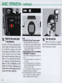
BASIC O P E R A T I O N - - - - - - - - - - - -
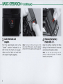
1
Set the openl closed knob
• ® on the flash unit coupler
to the OPEN position.
2
Attach the flash unit
. coupler to the flash unit.
Position the flash unit and flash unit
coupler, so that the secondary flash
head ® on the flash unit and the sensor (J) on the flash unit coupler face
the same direction . Insert the positioning claw ® into the slot ® on the
flash unit.
Then , whi le applying pressure to the
open/closed knob, push the flash
unit coupler into the flash unit until it
clicks into place .
Note: If batteries have already been installed in
the battery chamber. make sure the ON/OFF
switch ® is at the "o ff " position to avoid accidental firing.
7
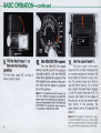
-BASIC OPERATION-confinued----------
3
4
lock the flash unit
. coupler.
Turn the open/closed knob to the
"c losed " position (indicated by a
dot) to lock the flash unit coupler ;
make sure the flash unit and flash
unit coupler fit tightly together.
8
Remove the Battery
. Holder MS·5 @ .
Note : To remove the flash unit coupler. set the
knob to the OPEN position. and while applying
pressure to the knob. gently pull the coupler off.
Open the battery chamber lid @ by
sliding it in the direction of the arrow
and remove the battery holder.
Note: You may feel slight tension when re moving or replacing the holder. This tension.
however. can be ignored.
5
6. Replace the holder.
7.
Load four 1.5V AA-type penlight
alkaline-manganese cells or 1.2V
rechargeable NiCd batteries into the
holder, making sure that the positive
and negative (+ and -) terminal s
match the diagrams on the holder.
First, make sure the power switch
@ of the flash unit is at the " off "
position ; then put the holder back
into the chamber, so that the slots at
both sides of the holder are aligned
with the guide rails inside the battery
chamber.
While applying pressure to the
battery holder with your finger, slide
the lid as far as it will go until it clicks
into place .
Load the batteries into
. the holder.
Close the lid.
Notes :
1) Use of manganese batteries is not recom mended because their power is insufficient
for operating the S8-16 at full capacity.
2) Do not mix brands or types of batteries. Also,
avoid mixing new and old batteries since
proper performance will not be obtained.
9
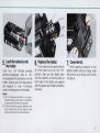
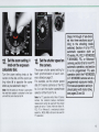
-BASIC OPERATION-confinued----------
8
With the 5B·16A, turn the locking
ring @ around the mounting foot @
counterclockwise until the AS-8 's
foot is uncovered (fig. 1). Then slide
the mounting foot onto the camera 's
accessory shoe as far as it will go
(fig. 2). Finally, tighten the locking
ring to prevent the unit from acci dentally slipping off (fig . 3).
Attach the flash unit to
. the camera's accessory
shoe.
Notes:
1) If you are using an F3-series camera, make
sure that the ASAIISO film speed is already
set on the camera before attaching the flash
unit, as the camera's ASAIISO dial cannot
be changed after the flash is attached to the
accessory shoe.
2) For the Nikonos- V camera, an optional V- Type
Sync Cord is required. For details about flash
unit attachment to the Nikonos-V, refer to the
Sync Cord's instruction manual.
10
With the 5B·16B, turn the locking
nut @) on the mounting foot ® counterclockwise until it reaches its upper
limit (fig. 1). Then slide the mounting
foot forward into the shoe as far as it
wil l go (fig. 2). Finally, tighten the
locking nut to prevent the unit from
accidentally slipping off (fig. 3).
11
-BASIC OPERATION-confinued----------
9
10.
Tilt the flash head 90°, so that it
faces straight ahead ,
Turn the ASA/ISO film speed
setting ring @ around the exposure
calculator dial @, until the ASAIISO
index @ is opposite the speed of the
film loaded in your camera. Also confirm that the film speed is properly
set on the camera.
Tilt the flash head ® to
. the normal shooting
position.
Set ASAIISO film speed.
Note: For TTL operation with the F3-series, FA,
FE2, FG or Nikonos-V cameras, the usable film
speed range is from ASAIISO 25 to 400 (with no
exposure compensation). With F-5011N2020 and
F-3011N2ooo, the usable film speed range for
TTL operation is ASAIISO 25 to 1000,
12
11 . Set the zoom head (j]) •
Pu ll out or push In the zoom
head until the number indicated with
an orange background matches the
focal length of the lens on your camera, For lenses longer than 85mm ,
use the 85mm setting , For a 24 mm
lens, attach the Wide -Flash Adapter
CD with the zoom head set at Wl , To
prevent light falloff at the edges of
the picture , do not use lenses wider
than 24mm, In the example , the
zoom head is set at 35 opposite the
letter N,
Note: When the subiect is closer than 1 meter,
it is recommended that you use a loom setting
which is one step less than the lens toea I length
(e,g. use the 35mm setting with a 50mm lens),
12.
13.
Turn the zoom setting knob at the
center on the dial until the zoom setting index @ is opposite the same
letter as you selected in step 11 .
The proper shutter speed setting for
flash synchronization of each camera is listed on page 21 .
For example, set the shutter speed
dial of F3-se ries cameras or the FE2
to A or set the shutter speed/mode
selector of the FG to P or A.
the zoohm setting @
Set b
kno on t e exposure
calculator dial.
Note: The W, setting on the dial is used when
the wide· flash adapter is attached to the flash
unit with the zoom head set at Wi.
Set the shutter speed on
the camera.
Steps 14 through 17 are divided into three sections according to the shooting mode
selected. Section A is for TTL
automatic operation (with an
F3-series, FA, FE2, F-501/N2020,
F-301/N2000, FG, or Nikonos-V
camera), section B is for non.:rTL
automatic operation, and section
C is for progammed TTL auto
operation (with the F-501/N2020
or F-301/N2000 camera set at a
programmed exposure mede).
For manual operation and synchronization with motor drive,
see pages 23 and 24.
Note: For TTL operation with a Nikon F3·series
camera, the camera's backup mechanical
release lever cannot be used with the shutter
speed dial set at T (time). With the Nikon FA ,
FE2, FG or Nikonos -V, a mechanical shutter
speed !i.e., M250, M90 or B) cannot be used for
TTL operation.
13
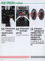
-BASIC OPERATION-continued-----------
A-14
Set the S8·16's mode
. selector (45) to TTL
Slide the mode selector to the right
as far as it will go, so that the index
on the selector is opposite the square
mark for automatic through-the-Iens
(TTL) flash exposure control.
With the F-501/N2020 or F-301/N2000
camera , set the camera's exposure/shooting mode selector to A or
a manual setting.
14
A-15.
Choose an flstop
from the exposure
calculator dial.
Depending on how far away your
subject is from the came ra, you must
se lect an appropriate working aperture by referring to the calculator
dial . You 'll notice that each IIstop
(from 112 to f/22) has its own colorcoded lin e @ above the whi te dis tance sca le @ indicating the range
of distances at which you can shoot.
For example , if you are using ASA/
ISO 100 film with the zoom head set
at N (35mm) and want to shoot subjects up to 4 meters (13 ft.) away, you
can select 118 , 114 , 112.8 or 112 . At f/4 ,
the automatic shooting range indi cates you can shoot any subject
between 1.4 and 8.0 meters (46 and
26 ft.) away
A-16
Set the lens aperture
. ring to the appro·
priate fI stop.
8-14.
If you decide to shoot at f/4, then you
must set the aperture ring on the
lens to f/4 .
For non-TTL automatic operation ,
the exposure calculator dial provides
a choice of two f/stops. The blue and
orange lines @ at the bottom of the
dial show the usable f/stops. For
example , with ASAIISO 100 film , you
can choose f/8 or f/4. The auto
shooting ranges with the zoom setting
Choose an f/stop
from the exposure
calculator dial.
at N (tor a 35mm lens), are 0.6 to 4
meters (20 to 31 ft.) and 0.6 to 8
meters (20 to 26 ft), respectively.
Note: The closest shooting distance for non TTL automatic operation is always 0.6m 12.0 It.!
regardless 01 the film speed and aperture you
select. With the zoom head set at T. however,
the closest distance is o.8m 12.6 It.!.
15
-BASIC OPERATION-continued----------
B-15
Set the mode selector
to the blue or
orange dot for automatic
operation.
• @
If you select 1/4, you must set the
selector to the orange dot, corres ponding to f/4 on the exposure calculator dial.
16
B-16
Set the lens aperture
. ring to the appro·
priate f/stop.
In the example, 1/4 is set on the lens.
C-14
Set the exposure
. mode selector of the
F·501/N2020 to P DUAL, P or
PHI, or set the shooting
mode selector of the
F·301/N2000 to P or PHI.
For programmed TTL auto flash
photography, use AI·S type lenses
only.
I
•
2
....
r
I
MD
l
(I
M
fffIl
~
I
For TTL operation
I
• •
,
Al
, )
(
A2
MD
I
{
.o.
II
C-15.
S~t ,lens to the
minimum aperture
(largest f·number),
C-16.
to TTL.
Set the 58·16'5
mode selector
For automatic
operation (A2)
17.
Turn on the flash
unit.
Slide the S8-16's ON/OFF switch to
the right. Immediately, an LED will light
up (green LED for TTL operation , or
red A1 or A2 LED for automatic
operation).
Note: The LED may blink for a short while after
the flash unit is turned on. This does not indicate
a malfunction.
17
-BASIC OPERATION-continued----------
18.
Wait for the ready· light
@ tocomeon.
As soon as the flash ready-light built
into the back of the flash unit comes
on , the 88 -16 is ready to fire. With
the except ion of the Nikon F2 -series,
if your camera has an LED readylight inside the viewfinder, make sure
that it is lit up, indicating that the 8816 is ready to fire. Note that with the
Nikon FA, FE2, F-501/N 2020, F-3011
N2000, FG, FG-20 or Nikonos-V, you
must first turn on the exposure meter to
activate the finde r ready-l ight.
18
Notes:
1) With the 58-16A and F3·series cameras
If both ready·fights blink, make sure that:
a. The flash unit is securely locked in place.
b. The film speed setting on the camera is
within the usable range when the flash unit
is used in the TTL mode.
With the 58-168 and FA, FE2, F-5011N2020,
F-301IN2000, FG or Nikonos-V
If the camera 's ready·light blinks, check to
see if:
a. A mechanical setting is not used in the
TTL mode.
b. The film speed setting on the camera is
within the usable range when the flash unit
is used in the TTL mode.
For more detailed information about the
ready-light warning, refer to page 37.
2) If the ready·light does not come on, first make
sure the batteries are properly installed. If
they are, replace them with a fresh set.
19
Take the picture.
• When the shutter is tripped,
both the main and secondary flashes
fire as the picture is taken.
20. Turn off the flash unit.
After you take the shot, watch the
ready-light inside the camera 's viewfinder or the one on the 88 -16. After
a short while , it will light up again to
tell you the flash unit is recycled and
ready to fire for the next shot.
To conserve battery power
between shooting sessions , slide the
power switch to the left.
Note : If the flash unit fired at its maximum
output, the ready-light blinks as a warning im medialely following the shot to indica te there
still may be underexposure. In this case. check
the combination of shooting distance and
aperture setected. and use a wider aperture or
move closer to the subject If necessary. This
warning is also provided in the viewfinder of all
Nikon ca meras having a built -in ready-light
(except F2-series cameras).
19
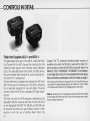
-CONTROLS IN D E T A I L - - - - - - - - - - - -
AS-8
Flash Unit Couplers AS·S @ and AS·9 ®
The detachable lower part of the SB -16, cal led the Flash
Unit Coupler AS-8 or AS-9 , houses the mounting foot , the
shooting mode selector with shooting mode indication
LEDs , the ready-lightlopen -flash button , the light sensor,
the sync/multiple flash terminal @, and the special ter minal @ for TTL multiple fla sh.
The only difference in appearance between the AS -8 and
AS -9 is the type of mounting foot. The AS-8 's mounting
foot is specially designed for use with Nikon F3-series
camera , while the AS -9 has a standard ISO-type mounting foot.
The flash unit with the AS-8 attached is identified as the
Speed light SB -16A, whereas the flash unit with the AS -9
as the Speedlight SB -16B. The SB-16A and SB-16B can
be mounted on almost any type of Nikon camera * either
directly or with the use of another Nikon Flash Unit
20
Coupler. The TTL automatic shooting mode, however, is
avai lable only when th e SB-16A is used with a Nikon F3se ri es came ra or wh en the SB -16 B is used with either the
Nikon FA, FE2, F-501/N2020, F-301/N2000, FG or NikonosV (via V.:rype Sync Cord). For more detailed informatin about
flash unit/camera combinations, refer to the table on page 5.
*Even with use of the Flash Unit Coupler AS-4 or AS-7, the S8-168 cannot
be used with F3-series cameras with the AF Finder OX-I, Action Finder
OA-2, Waist-Level Finder OW-3 or 6X Magnification Finder OW-4.
Note: 8e careful not to soif or damage the contact pins @on the coupler
or the contacts ® on the main flash unit as this may cause poor connec tion and possible malfunction.
Synchronization Speed
In flash photography, the shutter speed with which electron ic fl ash will synchron ize depends on the camera in
use. The table shows the usable shutter speeds with
variou s c ameras . As shown in the table, automatic
Hlko" cam.r.
1160 or slower
coupler)
11250 or slower
1/80
1120oo - I, , 2598 C '
e S8C. , X, Band T
All shutler speed settings except M 250 and B
In P, S and A modes '
114000 - 1/500 sec. In M mode "
112 50
FE.
'/250 or slower
FE·'
1/12Sorslower
FM 2 (wilh 1/250
sec.
sync s peed) " ·
FM2 (w ith 1/200
sync speed) ' •
1/250 o r slower
sec.
1/200 or slowe r
F· 50" N2020
F- 30 1 fN200Q
1 1125 or s lower
111 25 or slower
1
sec.
In M mode
M 250 and 8 In p. S, A and M modes
A , "4000 - 1/500 sec,"
1/250-B sec.
M 250 and B
AUlO"
1/125-8 , B
FG-20
Nlkonos-V
(via V-l'fpe Sync cord)
1/90 or s lower
Mao
LCD shows ma nual-set shutter speed ; no indication a t B or T
LCD shows 250
1/250
LCD s hows M250
as sel
LCD shows ma nua ll v-set shutter speed
No indicat ion
1 /250
as set
as set
1/90
11125-1 , X200 , B
1 / 125
11125-1 sec, and B
as set
PH I , p"
A, 1/2000
111 25
1/125
1/250 sec"
1 /125 sec ..
1/60 - 1 sec.
MOO and B
A. 1~ .111000 -1/ 1 25sec "
1 /60- 1 sec., M90 and B
A. 1I1000-1/125sec.
1/90 or s lower
80
1/250
P DUAL , P, PH I "
A , 1/2000 - 11250 sec"
P, A, 1/ 1000
1190 or slower
1/80
as set
1 /250- 1 sec" B
11125-1 sec. and B
FG
Viewfinder shutt.r ap••d Indlcallon
sp••d ( •• c .)
1/80
FA
(sec)
Actual shutt.r
Synch ronl zaUon
s p •• d (a.c.)
A"
F3-ssrles
(via AS· 4 or AS· 7
sync speed setting is available with Nikon F3-series, FA, FE2,
FE, F-501/N2020, F-301/N2000, FG, FG-20, EM and NikonosV cameras.
1 /60 - 1/30 sec.
MOO and B
1 / 125
as set
1/90
as set
as set
1/90
as set
1/90
125 light s up
125 light s up and LEO lor proper non-llash shuller speed blinks
LED lor manually-set s hulter speed lights up, and LEO lo r proper nonlIash shutter speed blinks ; no indication 81 B
t 25 light s up
125 lights up and LED lor proper non-fl ash shutler speed blinks
LED lor manually-sel s huller speed lights up. and LEO lor proper nonHash shutter speed blinks; no indication 8 t B
lWo LEOs repre senting 1/90 sec . light up
LEO lor m a nua lly-set shutter speed lights up
No i ndicaUon
LED or proper non-flash s hutler speed blinks
LEO tor proper non-llash shutter speed bUnks
No indication
-Automatic sync speed setting only occurs when the $8-16 Is mounted In the camera's hOi shoe and turned on; It does not occur when the S8-16 is turned of( or when sync cord Is used for off-camefa operation.
- • When the shutter speed dial setting Is higher than flash sync speed, the camera 's ready·llght blinks as a warning.
21
-CONTROLS IN DETAll-continued-------- -
ZoomHead @
The 88·16's zoom head has four settings which provide
various angles of coverage as shown in the table.
The number with an orange background indicates that
you can use a lens with the same or a longer focal length
at that setting. However, please remember that the lower
the numbered setting, the smaller the guide number and
the narrower the automatic shooting range is. (The guide
number and automatic shooting range for each zoom
setting is shown in the table on pages 31 and 32.). To set
the zoom head, simply pull it out or push it in until your
desired number appears with an orange background
behind it.
Notes:
1) With subjects closer than 1 meter, it is recommended that you select
a setting with a one·stop smaller number than the focal length of the
lens in use to reduce the amount of light at such close distances.
2) With the wide· flash adapter attached, you can usea 24mm lens.
22
Zoom head setting
Usable lens
Angle of coverage
Vertica l
Horizonta l
T········85
85mm or longer
23°
31°
$·· ..··50
50 mm or longer
34°
46°
N ..··35
35mm or longer
45°
60°
W,·28
28mm or longer
53°
70°
W, (with wide· flash
adapter)
24 mm or longer
60°
78°
control of the flash exposure at any aperture from fl2 to
fl22 to match the camera-to-subject distance: the farther
away the subject, the more light emitted by the flash
unit; the closer the subject, the less light given off.
Because the exposure is measured through the lens, no
exposure compensation is required in off-camera and/or
bounce-flash operation or even with a teleconverter or
filter attached to the lens.
This setting is also used for programmed TTL auto operation with F-501/N2020 and F-301/N2000.
Shooting Mode Selector @l
The shooting mode se lector on the back of the SB-16 has
five click-stop settings. Directly above the selector (read ing from left to right), there are the blue and orange dots
for non-TTL automatic operation, two white dots in the
middle indicating MD (Motor Drive) and M (Manual)
operation respectively, and a white square at the far right
which is for TTL operation.
As soon as the SB-16 is tu rned on , one of the appropriate
LEOs (green for TTL and red for all the rest) above the
selector lights up to indicate the setting selected.
Usable shooting modes depending on the combination of
the type of the flash unit and camera are as listed on
page 5.
TTL (through-the-Iens automatic operation)
This mode provides automatic through-the-Iens (TTL)
A (non-TTL automatic operation)
In the non-TTL automatic (A) mode, the light output of the
flash varies automatically to match the fla sh-to-subject
distance, but instead of the light being measured through
the lens, it is read by the light sensor on the front of the
SB-16. At any film speed setting , you have a choice of
two working apertures indicated by the blue A 1 and
orange A2 aperture indicator lines on the bottom of the
exposure calcu lator dial.
M (manual operation)
At the manu a ~ ~M) setting , the SB-16 fires at its maximum
light output regardless of the flash-to-subject distance.
When it is difficult to obtain correct exposure on auto, I. e ,
when the brightness of the background affects exposure
strongly, use the SB -16 on manual. In the manual mode,
exposure should be determined with the exposure ca lcu lator dial or with the guide number equation found on
page 30.
23
-CONTROLS IN DETAIL-continued--------MD (synchronization with motor drive)
At the motor drive (MD) setting , the S8 -16 is able to
recycle fast enough to synchronize with a motor-driven
camera firing continuously up to four frames per second .
It is possible to take up to eight flash pictures in rapid
succession in this way. At the MD setting , only the main
flash head fires and the light output is approx. onesixteenth that of the flash unit's maximum power. Like
the M setting , this setting is also for manual operation;
therefore , the exposure shou ld be calculated manually
using the exposure calcu lator dial or guide number
equation shown on page 30.
Note : As sufficient power is required for the flash unit to synchronize
with a motor drive, use the newest and freshest batteries whenever
possible. For the same reason, avoid tripping the shutter immediately
after the ready-light comes on. but wait for at least 30 seconds before
beginning the motor drive sequence.
Exposure Calculator Dial @
The exposure calculator dial on the back of the S8 -16
helps you select the aperture you must set on the lens
depending on the camera-to-subjectlflash-to-subject
distance. To use the dial, follow these steps:
1) Set the film speed
To set the ASAIISO film speed , turn the ASA/ ISO fi lm
speed setting ring until the number corresponding to the
speed of your film is opposite the ASA/ ISO film speed
index. Dots between the numbers on the film speed scale
represent intermediate settings.
24
2) Set the zoom setting knob
3) Determine the exposure
Turn the zoom setting knob at the center on the dial until
the zoom setting index is opposite the same letter as you
selected in setting the zoom head. For example , if you
set the zoom head at T for a 85mm lens, the zoom setting knob must also be set at T.
Depending on which shooting mode you 've selected,
read off the usable f/stop(s) from the dial. In either the
TTL or non-TTL automatic mode, more than one f/stop is
usable. When choosing an aperture , make sure that your
subject is within the auto shooting range indicated by the
color-coded lines. The larger the aperture (the smaller
the f-number) you select , the greater the maximum
shooting distance, whereas the smaller the aperture (the
larger the f-number), the less the maximum shooting
distance. If the subject distance remains the same , the
larger the aperture you select, the less depth of field in
the final photograph; however, the recycling time is
shorter. On the other hand , the smaller the aperture , the
greater the depth of field , but the recyc ling time is longer.
Therefore , in choosing an flstop , all these factors should
be taken into consideration .
Note: The W, setting on the dial is used when the wide-flash adapter is
attached to the flash unit with the zoom head set at WI.
25
-CONTROLS IN DETAIL-continued---------
For through·the·lens (TTL) operation
On the dial there are eight lis tops ranging from f/2 to
f/22 . Each IIstop determines the usable distance range
in which you can obtain the correct automatic exposure .
These ranges are indicated by a series of color-coded
lines above the distance scale.
For programmed TIL operation , it is not necessary to select
the lens aperture. Once the lens is set to its minimum aperture, the camera automatica lly selects the proper aperture
according to the lens in use. For information on the aperture
selected and automatic shooting range, see page 27 .
26
Example 1
If you are using ASAIISO 100 film (with the zoom head
set at N for a 35mm lens) and select f/4 , the auto shoot ing range is indicated by an orange line. Thus , you can
take pictures of subjects located between 1.4 and 8.0m
(approx . 4.6 and 26 ft.) from the camera .
Example 2
If you are using ASAIISO 400 fi lm (with the zoom head
set atT for an 85mm lens) and select f/4 , the auto shoot ing range indicated by the orange line thi s time is 3.8 to
21 m (approx . 12 to 69 ft.).
The auto shooting ranges for TTL photography are shown
in the lollowi ng table.
TIL auto shooting range
Unit: m (ft)
Film speed
(A5AJISO)
1000'
4
5 .6+1/3 5.6
Example 3
If you are using ASA/ISO 100 film (with th e zoom head
set at N for a 35 mm lens) and the subject is 2 m away,
you can select either 1/2.8 , 1/4, 1/56, 1/8, f/11 or f/16. If
a shorter recyc ling time is preferable, use 1/2.8. If greater
depth of fi eld is desi red, use 1/16.
T
S
N
W,
WI··
- - -
7.6-30
(26-98)
6.8-30
(22·98)
6.0-30
(20-98)
4.8-26
(16-85)
3 4· 19
- - -
5.3-29
(17·95)
4.8-26
(18-85)
4.0-22
(13-72)
3.4· 19
(11-62)
2.4· 13
(7 .9-43)
- -
3.8-21
(12-69)
3.4-9
(11-62)
3.0-16
(9.8-52)
2.4-13
(7.9-43)
1.7-95
(5.8-32)
-
2.7-14
(8.9-46)
2.4-13
(7.9-43)
20-11
(6.8-36)
1.6-9.5
(5.2-31)
(3.9-22)
1.9-10
(6.2-33)
1.7-9.5
(5.8-31)
1.4-8.0
(4 .8-26)
1.2-6.7
(3.9-22)
09-47
(3.0-15)
800 ' 400 200 100 50 25
2.8+113 2.8
4+113
Zoom heed setti ng
2
-
2.8
2
4
2.8
2
8+1/3
8
5.6
4
2.8
2
0.
11+113
11
8
5.6
4
2.8
2
~
16+1/3
16
11
8
56
4
28
22
16
11
8
5.6
0
-
(11-62)
1 2~ , 7
14·74
12-67
'0-56
(46-24)
(3.9-22)
(3 .3-18)
0.9-4 .7
(3.0-15)
06-33
(20-11)
4
1.0-5.2
(33-17)
0.9-4.7
(3.0-15)
0 .7-4 .0
(2.3-13)
0.8-3.3
(2.0-11)
0.6-23
(20-7 .5)
0.6-3.3
(2.0-11)
08-2.8
(2.0-9.2)
0.6-2.3
(2.0-7.5)
06-16
(2.0-5.2)
-
-
22
16
11
8
5.6
0 .8-3.7
(2.6-12)
-
-
-
22
16
11
8
0 .8-2.6
(2.6-8.5)
0 .8-2.3
(2.0-7 .5)
0 .6-2.0
(2.0-6.6)
0 .6-1 .6
(2.0-5.2)
08-1.1
(20-3.6)
-
-
-
-
22
16
11
0.8-1 .8
(2.6-5.9)
0.6-1 .6
(2.0-5.2)
0 .6-14
(2.0-4 .6)
0.6-1.1
(2.0-3.6)
0 .6-0.8
(2.0-2.6)
• For Nikon F-5011N2020 and F-3011N2000 only_
• ' W2 is used when the wide-ffash adapter is attached to the ffas h unit with
the zoom head set at W,
c=:J = Programmed TTL auto ffash in formation.
27
-CONTROLS IN DETAIL-continued---------
For non-TTL automatic (A) operation
For non -TTL automatic operation , you can select one of
two flstops , indicated by the blue and orange aperture
indicator lines at the bottom of the calculator dial. After
determining the aperture , set the shooting mode selector
corresponding to the aperture you selected .
28
Example 1
If you are using ASA/ISO 100 film (with the zoom head
set at N for a 35mm lens), the usable aperture is f/8 at
the blue A1 setting and f/4 at the orange A2 setting . The
automatic shooting range in this case is 0.6 to 4.0m
(2 .0 to 13 ft.) at A 1 and 0.6m to 8.0m (1 .0 to 26 ft.) at A2 .
For a subject more than 4m away, 'the only usable flstop
is f/4 . With a subject 3m away, you can select either f/8
or f/4 . If a shorter recycling time is preferable , use f/4 . If
greater depth of fi eld is desired, use f/8 .
Example 2
If you are using ASAIISO 400 film, the usable aperture is
now f/16 at A 1 and 1/8 at A2.
Auto shooting range
Zoom head setting
Unit: m(tt)
Shooting mode
T
The auto shooting range varies according to the zoom
head setting as shown in the table . At the same zoom
head setting, the range is the same regardless 01 the film
speed and the corresponding Iistop available at A 1 or A2 .
As you can see in the table , the closest subject distance
is always 0.6 m (20 It.) except at the T setting of the
zoom head.
Note: Regardless of the settings on the exposure calculator dial. any film
speed can be used for non· TTL automatic operation.
S
N
W,
W,'
Shooting range
A1
0.8-5.2 (2.6-17)
A2
0.8 -10 (26 -33)
A1
0.6 -4.7 (2.0-15)
A2
0.6 -9.5 (2 .0-31)
A1
0.6-4 .0 (2.0-13)
A2
0.6-8.0 (2.0 -26)
A1
0.6-3 .3 (2.0-11)
A2
0.6 -6.7 (2.0-22)
A1
0.6-2.3 (2.0-7.5)
A2
0.6-4.7 (2.0-15)
• W2 is used when the wide-flash adapter is attached to the flash unit
with the zoom head set at W, .
29
-CONTROLS IN DETAll-continued---------
For manual (M) operation
After setting the ASA/ISO film speed and zoom setting
knob on the exposure calculator dial , focus on the subject; then look at the lens and read off the focused distance to determine exactly how far away the subject
actually is. Now, find the end of the color-coded line
directly above the flash-to-subject distance and read off
the f-number next to this line. Then, set this aperture on
your lens.
30
Example
When using ASAIISO 100 (with the zoom head set at N
for a 35mm lens) and the subject is located 1.5m (5 .0 ft.)
away, the correct aperture is approx . f/22 . With a subject
3m (10 ft.) away, the aperture is approx. fl11.
Without referring to the exposure calculator dial , you can
also determine the flstop by using the following equation :
flstop
=
guide number
flash-to-subject distance
With ASAIISO 100 film and meters (and the zoom head
set at N for a 35mm lens), the S8-16's guide number is
32 . If the subject is 4 m away, divide 32 by 4 to get
fiB . Wi th ASAIISO 25 fi lm and feet (and zoom head set at
N for a 35 mm lens), the guide number is 52. Therefore,
if the subject is 20 ft . away, divide 52 by 20 to get approx .
f/2.B.
For motor drive (MD) operation
The guide number at various film speeds and zoom head
settings is shown in the following table:
Guide numbers in the manual mode
Zoom head
setting
T
S
Unit' m(tt)
ASAIISO film speed
800
400
200
100
50
After setting the ASA/ISO film speed and zoom setting
knob on the exposure calculator dial , focu s on the subject ; then look at the lens and read off the focu sed distance to determine exact ly how far away the subject
actually is.
25
119(390) 84 (276) 59 (194) 42 (138) 30(98) 21 (69)
107 (351) 76 (250) 54 (177) 38 (125) 27 (89) 19 (62)
N
90 (295) 64 (210) 45 (148) 32 (105) 22 (72) 16 (52)
W,
W,'
' 76 (250) 54 (177) 38 (125) 27 (89)
19 (62) 13 (43)
54 (177l 38 (125) 27(89)
13 (43) 9.5 (31)
19(62)
* W, is used when the wide-flash adapter is attached to the flash unit
with the zoom head set at W,.
31
-CONTROLS IN DETAIL-continued----------
Now, you are ready to read the usable f/stop from the
dial. Each color-coded line indicating the auto shooting
range for each f/stop has a notch on it. Find the notch
directly above the flash-to-subject distance and read
the f-number at the end of the line.
Example
With ASAIISO 100, zoom head set at N for 35mm lens,
a subject 2m (6 .6 ft.} away, the aperture is approx. f/4.
With a subject 4m (13 ft.) away, the aperture is f12.
Without referring to the exposure calculator dial, you can
also determine the f/stop by using the guide number
equation found on page 30.
32
The guide number at various film speeds and zoom head
settings is shown in the following table:
Guide numbers in the MD mode
Zoom head
setting
Unit· m(tt)
ASAIISO film speed
25
800
400
200
100
T
30(98)
21 (69)
14 (46)
10 (33)
7
5
27 (89)
19 (62)
13 (43)
9.5 (31)
6.7 (22)
4.7 (15)
N
W,
22(72)
16 (52)
11 (36)
8
(26)
5.6 (18)
4
19 (62)
13 (43)
9.5 (31)
6.7 (22)
4.8 (16)
3.3(11)
W2'
12 (39)
8.4 (28)
5.9(19)
4.2 (14)
3
• W2 is
50
(23)
(98)
5
(16)
(13)
2.1 (6.9)
used when the wide· flash adapter is attached to the flash unit
with the zoom head set at W,.
Exposure compensation
In TTL or non-TTL automatic operation with a dark subject (one with low reflectivity) or one light in tone (having
high -reflectivity), over- or underexposure may occur. To
prevent th is, exposure compensation is required .
Note : If you photograph a subiect of very high reflectivity. such as when
shooting directly into a mirror or metallic surface. underexposure is
certain to occur. In this case. take the picture on manual.
TTL exposure compensation
When shooti ng TTL auto fla sh pictures, you can use the
camera's exposure compensation dial (or the exposure
compensation button also available when using the
Nikon FG) in the normal way to make exposure compen sation according to the shooting situation or to make
intentionally over- or underexposed photographs .
Turn the dial in the + direction to give more exposure
and turn it in the oPPosite (-) direction to give less expo sure (refer to the camera 's instruction manual for more
information). The TTL auto shooting range changes
according to the amount of exposure compensation .
33
-CONTROLS IN DETAIL-continued---------
For example, if you are using ASAIISO 100 film with the
exposure compensation dial set at + 2 (overexposure),
you can read 25 from the table. Reset the exposure
calculator dial of the S8-16 to ASA/ ISO 25, and then the
correct TTL auto shooting range to match the com pen sated amount will be shown on the exposure calculator
dial.
ASAJISO film speed to set for TTL exposure
compensation
value
~n
+1
+2
0
-1
-2
50
100
200
400
800'
100
200
400
800'
Film speed In use
25
50
100
200
400
800'
1000'
.-/ /
/
25
50
100
200
250
25
25
50
50 100
100 200
200 400
400 800
500 1000
7
/
7
.-/ /
• For Nikon F-5011N2020 and F-301IN2000 only
= Not possible; make the necessary compensation in the non-TTL
automatic mode (see the following) or shoot on manual.
~
34
Non-TTL automatic exposure compensation
In the non-TTL automatic exposure mode, exposure
compensation can be performed by stopping down or
opening up the lens. With a dark subject , use a smaller
aperture. When a subject is light in tone , use a larger
aperture.
35
-CONTROLS IN DETAll-continued--------F3- series
FE2
FA
FE
FM2
F-501/N2020,
F-30 1/N2000
FG
FG·20
Ready· Light @
After the ON /OFF switch is turn ed on , the ready-light at
the back of th e 8B -16 lights up to indicate that the 8B -16
is recyc led and ready to fire. At the same time, the readylig ht inside th e viewfinder of all Nikon F3-se ries cameras,
in addition to the FA, FE2, FM2, FE, F-501/N2020,
F-301/N2000, FG, FG-20, EM and Nikonos-V also lights up.
Thus, without removing your eye from the eyepiece, you can
tell when the flash unit is ready for the next shot.
36
Notes:
I) With the Nikon FA, FE2, F-SO IIN2020, F-30 1IN2000, FG, FG-20 or
Nikonos-V, the meter must first be turned on by depressing the shutter
release button halfway to activa te the ready-light function.
2) The ready-light will light up when the S8-16 is recycled to approx. 80 %
full capacity. Therefore, it is a good idea to wait for a few more seconds
when shooting subjects located at the far limit of the auto shooting
range.
3) With alkaline-manganese batteries, if the ready-light takes more than
30sec. to light up, you should replace the batteries with a fresh set.
4) The voltage of NiCd batteries decreases rapidly when their power is
almost exhausted, increasing the recycling time. When this occurs,
stop using them immediately and recharge them or they may be
damaged.
Warning functions
In the TTL or non -TTL automatic mode, both the readylights on the fla sh unit and in the camera's viewfinder
blink for 3 seconds after the flash unit fired at its maximum output , indica ting that the light might have been
insufficient for correct exposure. In this case, check the
subj ect distance and if it is out of the automatic shooting
range, use a wider aperture if possible or move closer to
the subject. Because the voltage of batteries decreases
with use, the guide number might also be reduced slightly.
The flash output of the 88-16 depends on the available
ambient light and the reflectivity of the subject. Note that ,
because of these factors, the ready-light may blink to
indicate that the light output was insufficient for correct
exposure , even if the subject is within the auto shooting
rang e.
Other warnings shown by the ready-light's blinking vary
according to the type of flash unit and the camera in use.
(For more detailed information , refer to the tables on the
following pages .)
37
-CONTROLS IN DETAIL-continued--------With the SB·16A
As soon as the flash unit is turned on, both ready·lights
blink in the following cases :
1) When the AS-8 's mounting foot is not securely locked.
2) When using the TTL mode with the Nikon F3-series
camera and the camera 's film speed setting is set well
beyond the usable range of ASAIISO 25"'400, without
exposure compensation .
3) Wh en the shooting mode selector is set at TTL with
any camera other than the Nikon F3-series.
Note that when the shutter speed setting on the Nikon FE
or FM2 is improper for correct flash synchronization and
the camera 's meter is on (only in the case of the FE), just
the camera 's ready-light blinks as a warning, whi le the
one on the flash unit does not blink but simply lights up to
indicate when the flash is ready to fire.
38
Shutt.r .peed
Seili ng ( ••c .)
C.mer.
F 3· •• rle.
FA 'II. A S·'
All sel1ings
M25O. B
<In p. S, A and M modell)
TTL
M250, B
AUTO. 11125 or slower
FE 'II. AS· '
1/250 or r.ater
F·501 /N2020 'II. AS·',
F· 301/N2OOQ 'II. A S·'
1/250 or slower
1/500 or t ••ler
1 / 200 ( x 200) or s lower
11250 or t ••ter
Ail settings
All seUlngs except M90 and B
FO 'II. A S·'
M90, B
Ali settings except M90 and B
FO ·20 'II. AS·.
MOO, B
Nlkono.·Y
'II. Y'1'1pa Sync
Cord and AS·.
Al , A2, M , MD
TTL
F E2 'II. A S·'
FM 2 (with 11200 ••0.
aync .peed) 'I I. AS· '
TTL
All seUings except M250 and B
(In p. S, A and M modes)
All settings except M250 and B
FM2 (with 1/250 • • c.
a yno apead) via A S·'
Shooting mode
Ali settings except M90 and B
M90 , B
Al , A2, M , MD
Al.A2. M , MD
TTL
At , A2 , M, MD
TTL
Al, A2, M, MD
TTL
At, A2, M, MD
'tTL
Al.A2. M. MD
TTL
AI . A2, M , MD
TTL
Al,A2, M, MO
TTL
Al , A2 , M , MD
TTL
At, A2. M. MO
TTL
At , A2. M . MO
TTL
Al . A2. M . MO
TTL
Al , A2, M, MO
TTL
AI , A2 , M, MO
TTL
At , A2, M , MD
TTL
AI , A2 , M , MD
TTL
Al , A2. M, MO
SB·18A'.
re.dy· llght
Llghls up·
Lights up··
Blink.
Lights up··
BUnk.
Lights up· ·
Blink.
Light. up'·
Blink.
UghlS up ' ·
8l1nk.
Ughts up·"
8link.
Ught. up··
Blink.
Ughts up··
Blink.
Llghta up·"
BUnke
Ughts up··
Bllnka
L hi. up··
Blink.
LightS up··
8llnk.
Lights up··
Blinks
Lights up· '
Blink.
Lights up··
Blink.
Lights up··
Blink.
Lights up··
Blink.
Lights up· ·
Camer.'. read y· Ught
Meter ON
M.t erOF F
Lighls up·
Lights up·
Lights up· ·
Lights up· '
Blinks
Doe. not light up
Lights up'·
Does not 1I0hl up
BUnk.
Llghl. up··
Blink.
Doe. not Iloht up
Lights up··
Doe. not light up
Blink.
Lights up··
Blink.
8l1nk.
Ughts up· ·
Light. up·'
Blink.···
Blink.
Light. up··
BUnk.
stink.
Blink.
Lights up··
Ught. up"
Blink.···
Blink.···
Stinks
Blink.
Blink.
Blink.
Lights up· ·
Lights up··
Blinks···
Blink.···
Blink.
Blink.
Blink.
not light up
LightS up
Does not light up
Blink.
not II tu
Ughts up··
Does not light up
Blink.
Lights up··
Blinks
Doe. not Ughl up
Lights up··
Does not light up
8l1nk.
Lights up·'
Blinks
Doe. not II hi up
Lights up· ·
Does nOI light up
Blink.
Light s up··
eo..
eo..
'It blinks when the film speed setting on the camera is beyond the usable range for the TTL mode or when the mounting foot is not securely locked.
"It blinks when the mounting foot is not securely locked.
"'It blinks irregularly.
c::::::J = Proper flash synchronization is impossible due to improper setting of shutter speed or shocting mode.
Note: With a mechanical shutter speed set on the camera. the camera 's exposure meter remains off even if you depress the shutter release button.
39
-CONTROLS IN DETAIL-continued--------_
With the SB-16B
As soon as the flash unit is turned on , the ready- light on
the flash unit lights up when the flash is ready to fire ,
while the ready-light in the camera 's viewfinder blinks in
the following cases :
40
1) When the shooting mode selector is set at TIL with any
camera other than the Nikon FA, FE2, F-501/N2020,
F-301/N2000 , FG, or Nikons-V.
2) When using the FA, FE2, FG or Nikonos-V to perform TIL
automatic flash photography with the camera's shutter
speed dial set at a mechanical setting (M250, M90 or 8).
The B setting on the F-501/N2020 and F-301lN2000
camera is not a mechanical setting; you can use any setting on the camera's shooting mode selector.
3) When using the FA, FE2, F-501/N2020, F-301/N2000, FG
or Nikonos-V to perform TIL automatic flash photography
with a camera film speed setting over the usable range,
without exposure compensation (or when using DX-coded
film with film speed higher than ISO 1000 for the
F-501/N2020 and F-301/N2000). Make sure to use film
within the usable range for TIL flash photography (ISO
25 to 400 with the FA, FE2, FG or Nikonos-V, or ISO 25
to 1000 with the F-501/N2020 and F-301/N2000) .
With the FA, the ready-light also blinks when the film
speed setting on the camera is near ISO 12, with or
without exposure compensation in the + direction.
4) When the shutter speed setting on the FM2 or FE is improper for flash synchronization and the camera's meter
is on (only in the case of the FE).
Shutt.r .ptled
Setting (.ee.)
Camer a
F 3-•• rle.
v ia AS·4 o r 7
FA
All setti ngs
M250, B
(In p. S, A and M modes)
TTL
M250, B
AUTO, t 112 5 or slower
FE
1/250 or rsster
F·501 / N2020 ,
F ·30lIN2 000
t/250 or slower
1/500 or taater
t 1200 ( )( 200) or slower
11250 or rsater
All settings
All s81l lngs except M90 and B
FQ
MOO, B
All sell ings except MOO and B
FQ ·20
MOO, B
Nlkono.·V
v i a V.TYpe
Sync Cord
Al , A2 , M , MD
TTL
A1I selllngs except M250 and B
FM2 (wllh 1/200 •• e .
. yne . ptled)
TTL
A1I settings except M250 and B
(In p. S, A and M modes)
FE2
FM2 (wUh 11250 s . c •
• y n c . p.ed)
Shoot ing mod.
All settIngs except MOO and 8
MOO. B
At , A2 , M , MD
At , A2, M , MD
TTL
At , A2, M , MD
TTL
Al , A2, M , MD
TTL
At , A2, M, MD
TTL
Al,A2, M, MO
TTL
Al , A2 , M , MO
TTL
Al,A2, M, MO
TTL
Al , A2 , M , MO
TTL
Al , A2, M, MD
TTL
Al , A2, M , MD
TTL
AI , A2 , M , MD
TTL
Al , A2, M , MD
TTL
At , A2, M, MD
TTL
At,A2, M , MD
TTL
Al , A2. M, MD
TTL
Al, A2, M, MO
S8·188'.
r.ady· llght
LI ht. u
Light s up
L ights up
Ught s up
Lihgt. up
Ughts up
Ughts up
Lights up
Light. u
Ughts up
LI hts ~p_
Lights up
Lights up
Light. up
Light. up
Lights up
Lights up
Ught. up
Ught. up
Lights up
Lights up
LI ht. up
Lights up
Lights up
Lights up
Lights up
Light. ~p__
Lights up
Lights up
Lights up
Lights up
Lights up
Lights up
Lights up
Lights up
Lights up
Camera'. ready· light
Me'.rOFF
BUnks
Lights up
Does not tight up
Does not tI ht up
Slink.
Lights up
Lights up·
Does not light up
Light s up
Does not light UP
Slink.
Lights up
Slinks
Blinks
Lights up
Lights up
BUnke-Slink.
Slinks
Lights up
Blinks
Blinks
Lights up
Ughts up
Bllnks-Bllnka-BUnks
SUnk.
Blink.
B"nkO
Ughts up
Lights up
SUnk. .. •
Bllnk.·Blink.
Blink.
Lights up·
Does not light up
Lights up
Does not light up
Lights up·
Does not light up
Lights up
Does not light up
Slink.
Lights up
Blinks
Does no'! light up
Lights up
Does not light up
Blink.
Lights up
Lights up·
Does not light up
Does not light up
Lights up
BUnk.
Lights up
Me ••rON
SUnks
Lights up
Lights up"
LIghts up
·'t blmks when the film speed settmg on the camera is beyond the usable range for the TTL mode.
• • It blinks irregularly.
[==:::J = Proper flash synchronization is impossible due to improper setting of shutter speed or shooting mode.
Note: With a mechanical shutter speed set on the camera, the camera 's exposure meter remains off even if you depress the shutter release button.
41
-CONTROLS IN DETAIL-continued---------
Open- Flash Button @
The ready-light on the SB -16 can be used as an openflash button to fire the flash unit manually without having
to trip the camera 's shutter. In this manner, you can
create multiple-exposure "stroboscopic" effects or paint
the scene with light by firing the flash unit repeatedly with
the camera set at B. In this case, make sure that the
flash unit is not connected to the camera.
42
The open-flash button is also useful for test -firing the
SB-16 to determine whether the illumination from the
flash was sufficient for proper exposure in the non -TTL
automatic mode. With the shooting mode selector set at
one of the color-coded dots (A 1 or A2), push the" FLASH"
button; if it starts blinking, then you know the amount of
light might have been insufficient for the subject. In this
case, reset the se lector to A 1 if it was set at A2 , or move
closer to the subject. This test-firing is especially useful
when the flash head is tilted and/or rotated for bounce
flash.
In the TTL mode, test -firing must be performed by tripping the shutter. Note that , without film loaded in the
camera , the ready-light will blink even if the correct
exposure is obtainable . As a substitute for loaded roll
film , you can use a strip of cut film (provided it is not too
old) or a piece of gray paper.
43
-CONTROLS IN DETAIL-continued---------
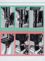
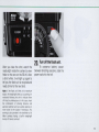
Tilting/Rotating Flash Head ®
For truly creative bounce flash photography, the 88 -16
has two flash heads.
The main head tilts back 90° wi th click -stops at the 30°,
45° , 60°, 75° and 90° positions. It also rotates through
an arc or 270°, 90° c lockwise with click stops at 30°,
60° and 90° positions, and 180° counte rc lockwise with
click-stops at 30°, 60°, 90°, 120°, 150° and 180° positions. To rotate it, push the flash head locking lever ® up
as you move the flash head until it clicks into place.
Notes:
1) In the MD mode, only the main head fires.
2) A special red LED is built into one end of the f/ashtube to ensure stable
light output. If you release the camera 's shutter or push the open-flash
button before the S8 -16 is fully recycled, the LED might light up-this
not a malfunction.
44
Secondary Flash Head ®
The smaller secondary head is built into the front of the
fla sh unit and faces straight ahead. Its purpose is to fill
in the shadows in the eye socket s and provide a ca tch light for the eyes when doing bounce flash . The secondary head has a guide number of 8.
45
-CONTROLS IN DETAIL-continued---------
Wide-Flash Adapter SW-7 CD
The Wide -Flash Adapter attached in front of the SB -16 's
main flash head with the zoom head set at WI (for a
28mm len s) increases the angle of coverage from the
70° horizontal and 53° vertical to 78° and 60° respectively, allowing the SB-16 to be used with a 24mm wideangle lens, With the SW-7 attached , remember to set the
zoom head knob on the exposure calculator dial at W2 .
46
Because the SW-7 diffuses the light emitted from the ·
SB -16, the guide number is reduced to 19 at ASA/ISO 100
and meters (refer to pages 31 and 32), and the auto
shooting ranges are less (refer to page 27 for the TTL
auto shooting ranges and page 29 for the non-TTL auto
shooting ranges).
TTL Multiple Flash Terminal @
The TTL multiple flash terminal is provided for TTL multiple flash photography. (For more information, refer to
pages 58-61.)
Sync/Multiple Flash Terminal @
Located at the side of the AS-8 or AS-9 is a threaded
terminal which serves two purposes: it can be used to
attach a sync cord to the 88-16 for off-camera operation
or you can attach a second electronic flaSh in series for
manual multiple lighting setups. (For more detailed information about manual multiple flash , refer to pages 58
and 62 .)
Notes:
I) When the S8-16 is used off-camera via a sync cord, ready-light indication inside the camera's viewfinder and automatic sync speed setting are
not available, and TTL auto flash operation cannot be performed.
2) When attached to an all-metallic accessory shoe, such as the one on
the Nikkormat FTN camera, the S8-16 does not fire even if it is connected to the camera body with a sync cord. In this case, isolate the
flash contact with vinyl tape or use the optional accessory sync cord,
SC-ID as required.
47
-PHOTOGRAPHIC TECHNIQUES--------Synchro-Sunlight Fill-In Flash Photography
A backlit subject , such as a person outside with hislher
back to the sun or indoors in front of a window, may
come out almost as a silhouette if the background is
correctly exposed . On the other hand, if exposure compensation is made to give the correct exposure for a
backlit subject , the background may be washed out. To
fill in the shadows and balance the illumination levels of
the subject and background , you can use an electronic
fla sh unit even in daytime.
One important fact to remember in balancing the exposure for both subject and background is thi s: Exposure
with a flash unit is determined only by the aperture
selected, whereas exposure for ambient daylight is
determined by a combination of shutter speed and
aperture.
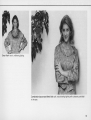
Without flash or exposure compensation :
the backlit subject
comes out too dark.
Without flash, but with
the exposure compensation dial set at
+2: the subject's face
is correctly exposed,
but the background is
too bright.
48
With fill-in fla sh: both the subject and the background come out properly exposed.
49
-PHOTOGRAPHIC TECHNIQUES-confinuedSynchro-sunlight fill-in flash photography is possible with
the S8-16's shooting mode selector set to the TTL-automatic, non-TTL automatic, or manual mode.
Operation in the manual mode assures you of good results in virtually all cases, so we will describe this procedure first.
In the manual mode
1) Set the shutter speed on the camera manually. Set
the camera manually to the highest synchronization
speed for electronic flash or a slower one.
2) Take a meter reading of the background. Frame the
background in the camera's viewfinder, so that the backlit subject is not included. Turn on the camera's exposure
meter to determine the proper f/stop for the shutter speed
you have set.
3) Determine the flash-to-subject distance. Using the
equation below, calculate the flash-to-subject distance
using the guide number for the fi lm in use (as shown on
page 31) and the f/stop set on the lens:
..
flash-to-subJect distance
guide number
f
Istop
4) Position the 58·16 at the correct distance. Set the
flash-to-subject distance on the lens distance scale; then
move in and out until the subject appears sharp in the
camera's viewfinder. To vary the composition , you can
use a wideang le-to-telephoto zoom lens. As an alternate
50
-
----
method, remove the flash unit from the camera using a
separate sync cord and position it at the correct distance;
then you can shoot from any position.
5)Take the picture. Set the S8-16 for manual operation,
turn it on and wait until it is fully recycled before taking
the shot.
This procedure balances the exposure for the subject
with that of the background. However, in synchro -sunlight
fill-in flash photography, it is a good idea to use the light
from the flash unit as a secondary light by decreasing the
flash illumination by approx. one or two stops to eliminate
harsh shadows caused by the ambient daylight. There
are two ways of decreasing flash illumination . One is to
use an aperture that's one or two flstops smaller than
that determined in step 2) in combination with a shutter
speed that should be slower by one or two steps to give
the background a correct exposure ; the other is to use
a flash-to-subject distance 1.4 or two times longer than
that determined through the equation . You will obtain
more natural-looking results with either method. You can
also combine the two methods. Some photographers
prefer to overexpose the background by one stop in order
to create an intentionally backlit effect by using a shutter
speed that's slower by a further one step.
In the TTL-automatic mode
In the non-TTL automatic mode
!~ Same as Steps 1) and 2) in the manual mode.
1) Set a shooting aperture on the lens. Read off the
two usable apertures from the exposure calculator dial
and set one of them on the lens.
3) Take the picture. With the S8-16 set at TTL and
turned on, just take the picture .
Notes:
1) With a strongly backlit subject (such as a scene containing the sun),
the desired exposure balance may not be obtained. In this case, use
the 8B-16 on manual.
2) To give different exposures to the subject and background, you can re set the camera 's shutter speed dial and exposure compensation dial
accordingly. For example, use a slower shutter speed to make the background overexposed and turn the exposure compensation dial in the direction to make the subject underexposed.
2) Take a meter reading of the background. Frame the
background in the camera's viewfinder and turn on the
camera's meter to determine the proper shutter speed
for the aperture you have set. Note that the shutter speed
should be within the flash synchronization range for the
camera you are using.
3) Take the picture. With the S8-16 set at A 1 or A2 and
turned on , take the picture only if a proper synchronization speed is available.
Notes:
1) Exposure is more easily affected by the brightness of the background
in the non- TTL automatic mode than it is in the TTL-automatic mode.
2) Because the usable apertures are limited in the non-TTL automatic
mode, a proper shutter speed to match the shooting aperture may not
be available.
51
-PHOTOGRAPHIC TECHNIQUES-continued-----Synchronization with slow shutter speeds
If you are using the 88·16 at a high shutter speed under
dim light, the background may come out too dark. To
avoid this, use a slower shutter speed. The procedure for
synchron ization with slow shutter speeds is the same as
that described before; however, you should mount the
camera on a tripod to avoid camera shake at speeds of
1/30sec . and below. Also, it is recommended that you
make the background somewhat underexposed .
52
Note: When using color film , especially transpa rency film, unnatural color
casts may occur when the ratio of flash illumination to ambientlightis low.
Fast synchronization speed: the background
is too dark.
Slow synchronization speed: now detaifs in the background can be seen.
53
-PHOTOGRAPHIC TECHNIQUES-continued - ----------:
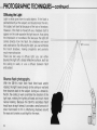
Diffusing the Light
Light is what gives form to solid objects. If the flash is
pointed direc tly at th e subjec t and loca ted near th e lens,
the subjec t will look fl at because of th e lack of shadows .
Howeve r, if the fla sh is moved off-axis , shadows sta rt to
appear on the side opposite the light sou rce , thus giving
the impression of roundness . But because the light sti ll
comes directly from the flash. the shadows are harsh
and unattrac tive. By diffusing the light, you can eliminate
the harsh shadows, making snapshots and portraits
much more attrac ti ve .
There are two ways to diffuse light : you can either
bounce the light off a broad reflective surface , such as
the ceiling or walls , or use a diffuser between flash
and subject.
91t
'i.'"
/~'ll
//I:~I
//'/1
1/1"
I/</~I/
/
I
I
I
I
/
/
I
I
I
/
f
I
I
I
I
I
I
/
I
"
/
I
/
I
I
I
I
I
I
/
/
I
/
I
I
I
I
/'
I
I
I
I
I
/'
"
I
I
/
I
I
I
I
I
I
Bounce flash photography
/
/ I / I/
I
I
54
I
I'
/
I
With the 8B -16's main flash head tilted back and/or
rotated , the light travels directly to the ceiling or wall and
then bounces back to the subject. Acting as a broad re flector, the ceil ing or wall scrambles the direction of the
light rays, making the lighting diffused and much more
natural looking. Because the 8B-16 's secondary flash
head faces straight ahead , it provides a small amount of
direct illumination to fill in unflattering shadows around
the eyes and creates a catchlight for the eyes.
/',/ /,'
/ / I/
I I
/ /
I
I
/' / I /,'
I I,/
I
:'
/
I
/
"
I
I
/
"
"
Combination bounce and direct fla sh: soft, natural-looking lighting with a pleasing catchlight
in the eyes.
55
-PHOTOGRAPHIC TECHNIQUES-confinued-----The procedure for bounce flash is as follows :
1) Choose the bounce surface.
Select the ceiling or wall you want to bounce the flash off
of ; then tilt and/or rotate the main flash head so that it
pOints in that direction. The position of the flash unit, the
bounce angle, and the setting of the zoom head should
be determined after considering the size and shape of
the subject and the effect desired . With a subject having
great depth , some light should reach the point furthest
away from the camera to create a three-dimensional
effect. For portraits , consider how much brightness you
want for the background.
2) Set the zoom head.
In bounce flash photography, a large amount of light is
required , because the light has to travel a longer distance
than in direct flash photography, and also the bounce
surface absorbs a certain amount of light. Therefore , it is
recommended that the zoom head be set at T. The ratio
of diffused illumination (from the bounce surface) to
direct illumination (from the secondary flash head) is also
an important consideration. If the bounce surface is too
far away or is not very reflective, the level of the diffused
illumination may be almost the same as the direct illumination , thus effectively cancelling the diffused lighting
effect. In this case, adjust the angle of the main flash
head or shorten the bounce distance so that there is
more difference in illumination levels.
56
3) Choose an aperture.
Test firing the flash is necessary, because exposure in
bounce flash photography depends on so many conditions, such as reflectivity of the bounce surface and the
bounce distance. Note that , in bounce flash , shooting
distance cannot be read with the exposure calculator dial.
4) Bracket your exposures_
It is recommended that you take additional shots, with
the camera 's exposure compensation dial set in the +
direction for TTL au tomatic shooting or with the lens
opened up one or two f/stops in the regular (non-TTL)
automatic mode .
Notes:
1) In general, there is a two or three flstop loss in illumination because
of the absorption of light by the reflective surface.
2) Unless the surfa ce of the reflector you are bouncing the light off of is
white or silver, your color photographs will come out with an unnatural
color cast similar to that of the reflecting surface.
3) When the flash head is tilted back 45° or less, some amount of light
from the flash head may reach the subject directly, causing uneveness
of illumination. To avoid this, make sure the head is tilted back 60°
or more.
4) In bounce flash, the angle of incidence is equal to the angle of re flection.
Using a diffuser
It is also possible to diffuse the light by placing a trans lucent material , such as one or mo re sheets of tracing
paper, between the flash and subject. You can create
more pronounced diffusion by placing a certain distance
between the diffuser and flash than by wrapping the
diffuser around the flash head. Experimentation with
different flash-to -diffuser distances and/or with more
than one diffuser is recommended .
Notes:
1) In non-TTL automatic shooting, make sure that the diffuser does not
come between the S8-16's sensor and the subject.
2) Some diffusion materials may cause a slight reddish tint in color photo graphs by decreasing the color temperature of the light from the fla sh.
3) When a diffuser is used, shooting distance cannot be read with the
exposure calculator dial.
57
-PHOTOGRAPHIC TECHNIQUES-continued-----Multiple Flash Photography
If you have another flash unit, you can use it as a secondary light source for multiple flash photography. When you
use only one flash unit in front of a subject, harsh shadows may be produced or light may not reach the background. But by using more than one flash unit, you can
solve these problems.
With the 8B-16 and F3-series, FA, FE2, F-501/N2020,
F-301/N2000, FG or Nikonos-V camera combination, both
TIL and manual multiple flash photography are possible. In
both cases, one important fact to remember is that the effect
produced by using more than one flash unit depends on the
lighting ratio or balance of illumination between flash units.
80 first you should determine the role of each flash unit,
deciding which flash will be the main flash and which the
secondary.
To create pictures with high contrast, give different exposure to the subject and background by adjusting the
aperture , shutter speed and/or camera-and flash-to-subject distance.
58
One flash unit:
standard, rather
static lighting.
l
.J
•
Two flash units:
dramatic lighting
resembling window
light.
TTL multiple flash photography
8y using the S8-16 connected to an F3-series, FA. FE2,
F-501/N2020, F-301/N2000, FG or Nikonos-V (via V~ype
Sync Cord) camera as a master flash unit and either the
Nikon 8peedlight 88-11 , 88-14, 88-15, 88-16, 8817, S8-18
and/or 88-140 as slave flash unit(s), TIL multiple flash
photography with up to five flash units can be performed.
To perform TIL multiple flash photography, use the
optional TTL Multi-Flash Sync Cord SC-18 (15m) and/or
SC-19 (3m) to connect the flash units together via the
TTL multiple flash terminal.
To use the S8-11 , S8-14 and/or S8-140 in TTL multiple flash
photography, the TIL Remote Cord SC-23 is required .
59
-PHOTOGRAPHIC TECHNIQUES-continued-----SYSTEM CHART FOR TTL MULTIPLE
FLASH OPERATION
@
ffiOfJ
Nikon F3
,Ikonos-v
-
0
V-Type Sync Cord
~
@~
~
@)
IJ~!5
~ ~ @~5B"
l1Jl9JJ
Nlkon F-5011
~-----+-!=~~
Nlkon FE2
SC-17
~L.-O-Q:r-~
-"--f-:-@)III~II
Nlkon F-3011
N2000
@~ @)~SB-18
Nikon FG
L -_ _ _ __ _-!
@ indicates the "master" flash unit.
"TTL multiple flash photography is possible onty with an F3-series,
FA, FE2, F-501IN2020, F-301IN2000, FG or Nlkonos-V came ra .
60
F~s."
~---- ~~S~=-2=3=-SB-11
ISB-14/
SB-140
~____.
O
--=
SB-16B
~-Ej
~
AS-11
IlIL
ail .,
o
SC-18
SC-19
~-El
~
AS-11
SB-141
SB-140
SC-18
SC-19
,jllJIlll-
SE? ~SB-18
61
-PHOTOGRAPHIC TECHNIQUES-confinued-----
Manual multiple flash photography
If the secondary flash unit is either a Nikon Speedlight
S8-11, S8-12, S8-14, S8-15, S8-16 or S8-17, use either
the SC-11 (approx. 25cm) or SC-15 (approx. 1m) sync
cord to connect the flash units together via sync/multiple
flash terminal. With the S8-7E or S8-10, use the SC-5
(approx. 15cm), SC-7 (approx. 25cm) or SC-6 (approx.
1m). All these sync cords are available as optional accessories .
Note: In manual multiple flash operation, make sure to use both flash
units on manual. In the TTL or non· TTL automatic shooting mode. the
correct exposure cannot be obtained. because light from each speedlight
affects the measurement.
62
Caution: The S8·16 employs a speciallow·voltage triggering circuit to
prevent electrical shock and damage to the hot·shoe contact. We do not
recommend mixing Nikon Speedlights with flash units of other makers for
multiple flash photography, unless you use slave units for remote trigger·
ing. Otherwise. incorrect operation and/or damage to the unit may result.
ACCESSORIES------------Sync Cords 10, 11 , and 15
TTL Remote Cord SC-14
For use with cameras not provided with a hot shoe or for
off-camera or multiple -flash lighting setups. The 8C-11 is
25cm while the 8C-15 is one meter. To use the 8C-1O with
F2 - or F3-series cameras, use of the Nikon Flash Un it
Coupler (A8-1 for the F2 and A8-4/7 for the F3) is required .
The 8C -1 4 enables the 8 B-16A to be used up to one
meter off a Nikon F3 -series camera for TTL automatic
flash operation .
TTL Remote Cord SC-17
SC -IO
SC -II
The coiled cord 8C-17 enables the 8B-15, 8B-16B or 8B-18 to
be used up to one and half meters off a Nikon FA, FE2,
F-501/N2020, F-301/N2000, or FG camera for TIL automatic
flash operation. Even with the 8C-17, automati c sync speed
setting and ready-light indication in the viewfinder are provided just as if the flash unit were mounted directly on the
camera. The SC-17 which has two terminals for TIL multiple
flash photography can be used to connect up to two slave
flash units when the 8B-16B is used as a master flash unit. A
tripod socket is provided.
SC -IS
63
-ACCESSORIES-continued-----------TTL Multi·Flash Sync Cords SC·18 and SC·19
Flash Tripod Adaptor AS·11
The SC-18 and/or SC-19 are used to connect the flash
units together for TTL multiple flash ope ration. The SC18 is 1.5m long , while the SC-19 is 3m.
The AS-11 enables the S8-16A. used as a slave flash
unit, to be attached to a tripod . Also , it preven ts the S816A ready-light from blinking for no reason and lets you
see when the flash is ready to fire
and whether or not the flash fired
at its maximum output.
TTL Multi·Flash Adaptor AS·10
When you plan to perform TTL multiple flash operation
with more than three flash units or to use the S8-15 or
S8-18 as a slave flash unit, the AS-10 is required. With
one AS-10 having three TTL multiple flash terminals , you
can use up to three slave flash units including one
mounted on it.
A tripod socket at the bottom enables the S8-168
mounted on the AS-10 to be fi xed to a tripod . To perform TTL flash photography with two units using the S8168 as a slave flash unit or to perform TTL photography
with three units using the S8-168 as a master flash unit
mounted on the SC-1?, use of the AS-10 is not always
needed. Without the AS-10 , however, the electrical contacts on the flash unit are uncovered
and can be the cause of incorrect
output control.
64
Flash Unit Couplers AS·1, 4, 5, 6, and 7
The AS-1 , AS-4, or AS-? convert the accessory shoe of a
Nikon F2 - or F3-series camera to the standard ISO-type
accessory shoe, allowing direct attachment of the S8168. The AS-1 is for the F2-series camera and the AS-4
and? are for the F3 -series camera. A special feature of
the AS-? is that it lets you change film without removing
the flash unit.
The AS-6, on the other hand, is used when you want to
mount the S8 -16A directly on the Nikon FA, FE2, FM2,
FE, F-501/N2020, F-301/N2000, FG, FG-20, EM or FM
camera. To mount the S8-16A on an F2-series camera,
the AS-5 is required .
"RED EYE"-----Soft Flash Unit Case 55·16
The SS-16 accommodates the main flash unit of the S8-16
and both Flash Unit Couplers AS-8 and AS -9, one attached to the main flash unit, and one stored separately
inside the pocket , with the Wide -Flash Adapter SW-7
attached to the flash head. If you do not store a flash unit
coupler in the pocket , then you can put the SW-7 inside
the pocket instead of attaching it to the flash head. The
pocket can also be used to store spare batteries.
Note : In storing the coupler or adapter inside the pocket, never put them
together or anything else with it. If you do so, the electrical contacts on
the mounting foot of the coupler or the glass surface of the adapter may
be damaged.
" Red eye" is a phenomenon in flash photography where
the center portions of the subject's eyes appear as bright
red orbs in color photographs (or white in black and white
pictures). This is a result of the light from the flash illumi nating the retina directly. If the subject looks straight into
the lens and there is little or no ambient light, the pupil is
wide open , making the retina clearly visible in the picture .
To avoid "red eye ," you can take any or all of the following precautions :
1. Ask the subject not to look directly into the lens when
the picture is taken .
2. Remove the flash unit from the camera and hold it as
far away as possible from the camera by using a sync
cord.
3. Increase the room's overall illumination to reduce the
opening of the subject's pupils.
65
TIPS ON SPEEDLIGHT C A R E - - - - - - - - -
- To remove dirt or fingerprints, wipe
with a dry soft or silicon-treated
cloth . Never use thinner, benzine or
alcohol, since they might damage
the plastic parts . To clean the WideFlash Adapter, wash it with soap
and water. Never use a brush, as
this may damage it.
66
-If you do not plan to use the unit for
more than two weeks, remove the
batteries to avoid possible damage
to the circuitry by battery leakage.
If leakage should inadvertently
occur, take the flash unit to your
nearest Nikon authorized service
facility.
- To prevent damage to the flash
unit 's electronic circuitry, keep the
camera away from places where
the temperature is likely to go higher
than 50°C, such as inside the trunk
of a car in the hot summer sun ; also
do not store the unit in exceptionally
damp places. Use the 88-16 within
the range of -1Q°Crv+50°C.
-If your 88-16 has not been used for
a long time , its recycling time may
be longer, To maintain the built-in
condenser in peak condition , thereby enabling you to use the 88-16 for
many years , fire the flash unit a few
times every month , After firing, wait
until the ready-light lights, then turn
off the power switch , remove the
batteries, and store the 88-16 in
a su itable location , This will pre vent the condenser from deteriorating ,
- Keep the flash unit away from salt
water and out of the rain ,
- Never attempt to disassemble or
repair the flash yourself. These delicate procedures should be left to
an authorized service facility,
67
OPTIMUM BATTERY PERFORMANCE------New batteries. Between manufacturing and first use, all
batteries exhibit some drain. Therefore , care should be
taken to purchase the newest (and freshest) ones possible. To help you do this , some manufacturers stamp the
date of manufacture on the bottom of each battery. Ask
your camera dealer for assistance in interpreting the
codes .
Temperature. Battery life ratings are based on operation
at around 25°C (7r F), At other temperatures, battery
life is shortened. Spare batteries should therefore be
kept available if operation in low temperatures is anticipated.
Continuous use. Batteries are drained much more
quickly by continuous use than by intermittent use.
Storage. When not in use, the batteries should be removed to prevent damage from leakage. To minimize
drain during the period of disuse, store the batteries in a
cool , dry place below 20°C (68°F),
68
Battery brands. Do not mix brands of batteries, nor use
batteries with different model numbers. Also , avoid mixing new and old batteries since proper performance will
no be obtained and battery leakage may occur.
Disposal. Do not dispose of batteries by burning . Also,
for safety's sake , never disassemble batteries.
Polarity. When installing batteries, observe the voltage
polarities carefully. Reversal of the positive (+) and negative (-) termina ls will result in leakage. If leakage should
occur, take the SB-16 to your dealer.
NiCd batteries. In comparison with regular batteries ,
NiCd batteries provide faster recycling time and better
efficiency at low temperatures . However, note that the
recycling time and the number of flashes per battery set
are dependent on the age of the batteries, how much
charge they have, and their capacities.
SPECIFICATIONS------------(The SB -16 main flash unit has the following specification s when
combined with the Flash Unit Coupler AS-8 or AS -9)
Electronic construction
Guide number at ASA/ISO
100 and meters (or at
ASAIISO 25 and feet)
Angle of coverage
Flash heads
Zooming capability
Automatic silicon· controlled
rectifier and series circu itry
At full output: 32 (52) with the
zoom head set at N ; 19 (33)
with the zoom head set at WI
and Wide· Flash Adapter SW-7
attached
60° horizontal and 45° vertical
with the zoom head set at N ;
78° horizontal and 60° vertical
with the zoom head set at WI
and Wide· Flash Adapter
attached
Two flash heads provided ; main
head tilts back 90° with click ·
stops at the 30°, 45°, 60°,
75° and 90° positions and also
rotates through an arc of 270°,
90° clockwise with click stops
at 30°, 60° and 90° positions,
and 180° counterclockwise with
click·stops at 30°, 60°, 90°, 120°,
150° and 180° positions; the
smaller secondary head faces
straight ahead to provide a catchlight for the eyes
Possible with four settings (T, S,
N and WI for 85mm , 50mm,
35mm and 28mm lens
Batteries
Four 1.5V AA·type alkaline·
manganese penlight batteries
or four 1.2V AA-type NiCd
batteries recommended
Number of flashes and recycling time
(on manual at 25°C)
Number of flashes'
Recycling time '
Alkaline·manganese
Battery type
approx. 100 times
approx. 11 sec . minimum
NiCd "
approx. 40 times
approx. 8 sec. minimum
'At full output ; of course, more flashes and shorter recycling times are
possible in the TIL, non·TIL automatic, or MD mode
.. This data depends on brand of battery and amount of recharging
TTL auto exposure
Non-TTL auto exposure
Through-the-Iens automatic exposure control when the S8-16A
is combined with the Nikon
F3-series camera or when the
S8-168 is combined with the
Nikon FA, FE2, F-501/N2020,
F-301/N2000, FG or Nikonos-V;
film speeds from ASAJISO 25 to
400 with the FA, FE2, FG or
Nikonos-V, or ASA/ISO 25 to 1000
with F-501/N2020 or F-3011
N2000; usable aperture range
from f/2 to 1122
Automatic exposure control via
the front·mounted light sensor ;
two working apertures depend·
ing on film speed (118 and 114
at ASAIISO 100) are usable and
identified as A 1 and A2
69
-SPECIFICATIONS-confinued----------Manual exposure control
Synchronization with
motor driven camera
Dimensions (W x H x D)
SB·16A
SB·16B
Weight
SB·16A
SB ·16B
Accessories provided
Full output at M setting
Possible at MD setting with
1/16th of full output ; guide
number is 8 at ASA/ISO 100 aM
meters (or 13 at ASA/ ISO 25
and feet) with the zoom head
set at N ; only main flash fires
approx . 82mm x 166.5mm x
100mm
approx. 82 mm x 144 mm x
100mm
approx. 485g (without batteries)
approx. 445g (without batteries)
Wide · Flash Adapter SW-7 ;
Soft Case SS -16 ;
Battery Holder MS-5
Specifications and designs shown herein are subject to change without
notice.
70
71
(1IIIro,,)
No reproduction in any form of this manual, in whole or in part
(except for brief quotation in critical articles or reviews). may be
made without written authorization from Nippon Kogaku K.K.
NIPPON KOGAKU K.K.
Fuji Bldg., 2-3, Marunouchi 3-chome, Chiyoda-ku, Tokyo 100, Japan
Phone: 81-3-214-5311 Telex: J22601 (NIKON) Fax: 81-3-201-5856
Prin ted in Japan 8& 137-E 06