1
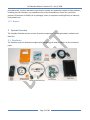
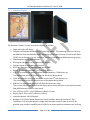
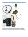
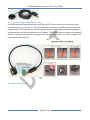
NK ClearNav Manual • Version 0.5 • July 3, 2008 Page 1 of 86 NK ClearNav Manual • Version 0.5 • July 3, 2008 Page 2 of 86 NK ClearNav Manual • Version 0.5 • July 3, 2008 Contents 1 2 Introduction ........................................................................................................................................ 9 1.1 Contributors ............................................................................................................................... 10 1.2 Updates ...................................................................................................................................... 10 1.3 Step‐by‐Step Directions Format ................................................................................................. 10 1.4 Macintosh Computer Users ....................................................................................................... 11 1.5 Important Notices ...................................................................................................................... 11 1.5.1 Before You Fly ..................................................................................................................... 11 1.5.2 Fly Safely ............................................................................................................................. 12 1.5.3 Not a Certified Instrument .................................................................................................. 12 1.5.4 Warranty ............................................................................................................................. 12 1.5.5 Repairs ................................................................................................................................ 13 System Overview .............................................................................................................................. 13 2.1 Hardware .................................................................................................................................... 13 2.1.1 ClearNav Display ................................................................................................................. 15 2.1.2 ClearNav Handheld Remote ................................................................................................ 16 2.1.3 ClearNav Stick Mounted Remote ........................................................................................ 16 2.1.4 Nexus Wiring Board ............................................................................................................ 17 2.1.5 ClearNav In‐Panel Mounting Kit.......................................................................................... 20 2.1.6 RAM Mount Kit ................................................................................................................... 21 2.1.7 ClearNav DB15 Extension .................................................................................................... 23 2.1.8 GPS Antenna ....................................................................................................................... 24 2.1.9 Panel Mounted CAN/USB Extension ................................................................................... 25 2.1.10 External Devices .................................................................................................................. 25 Page 3 of 86 NK ClearNav Manual • Version 0.5 • July 3, 2008 2.1.10.1 USB Flash Drive ............................................................................................................ 26 2.1.10.2 Cambridge Aero Instruments 302 ............................................................................... 27 2.1.10.3 FLARM .......................................................................................................................... 28 2.2 Software ..................................................................................................................................... 28 2.3 Data Files .................................................................................................................................... 28 2.3.1 2.3.1.1 Worldwide Soaring Turnpoint Exhange (.stx) files ...................................................... 29 2.3.1.2 Cambridge (.dat) files .................................................................................................. 29 2.3.1.3 SeeYou (.cup) files ....................................................................................................... 29 2.3.2 Airspace Files ...................................................................................................................... 30 2.3.2.1 Tim Newport‐Peace (.sua) files.................................................................................... 30 2.3.2.2 OpenAir (.txt) files ....................................................................................................... 30 2.3.3 Worldwide Soaring Turnpoint Exchange ............................................................................ 30 2.3.3.1 Downloading .stx Waypoint Files from the Worldwide Soaring Turnpoint Exhange .. 30 2.3.3.2 Downloading Airspace Files from the Worldwide Soaring Turnpoint Exhange .......... 31 2.3.4 Elevation Data ..................................................................................................................... 32 2.3.5 Shape Data (Cities, Rivers, Lakes and Roads, etc.).............................................................. 32 2.4 3 Waypoint Files..................................................................................................................... 29 Putting it All Together ................................................................................................................ 32 2.4.1 How it Works ....................................................................................................................... 32 2.4.2 What it Does Do .................................................................................................................. 32 2.4.3 What it Doesn’t Do ............................................................................................................. 32 Installation ........................................................................................................................................ 33 3.1 ClearNav Display ......................................................................................................................... 33 3.1.1 On Front of Panel ................................................................................................................ 33 3.1.2 Recessed into the Panel ...................................................................................................... 33 Page 4 of 86 NK ClearNav Manual • Version 0.5 • July 3, 2008 3.1.3 4 On a RAM Mounting Arm ................................................................................................... 33 3.2 GPS Antenna ............................................................................................................................... 33 3.3 Handheld Remote Control ......................................................................................................... 33 3.4 Stick Mounted Remote Control ................................................................................................. 33 3.5 Panel Mounted CANbus/USB Extention .................................................................................... 33 User Interface ................................................................................................................................... 34 4.1 Remote Control .......................................................................................................................... 34 4.1.1 Zoom In (+) Button .............................................................................................................. 35 4.1.2 Zoom Out (‐) Button ............................................................................................................ 36 4.1.3 Menu Button ....................................................................................................................... 37 4.1.4 Focus Button ....................................................................................................................... 38 4.1.5 Select Button ....................................................................................................................... 38 4.1.6 Arrow Buttons ..................................................................................................................... 39 4.2 Navigation Display (moving map, etc.) ...................................................................................... 40 4.2.1 Data at the Top of the Screen ............................................................................................. 41 4.2.1.1 Destination Window .................................................................................................... 41 4.2.1.2 Distance Window ......................................................................................................... 41 4.2.1.3 Final Glide “Altitude Differential” Window ................................................................. 41 4.2.2 Ribbon Menu ...................................................................................................................... 43 4.2.2.1 Select Destination Icon ................................................................................................ 43 4.2.2.2 Bugs Icon ...................................................................................................................... 44 4.2.2.3 Water Ballast Icon........................................................................................................ 45 4.2.2.4 Map Orientation Icons ................................................................................................. 45 4.2.2.5 Backlight Intensity Icon................................................................................................ 46 4.2.2.6 Task Edit Icon ............................................................................................................... 47 Page 5 of 86 NK ClearNav Manual • Version 0.5 • July 3, 2008 4.2.2.7 Map Icon ...................................................................................................................... 48 4.2.2.8 Simulator Icon .............................................................................................................. 51 4.2.2.9 Setup Menus (Brief Intoduction) ................................................................................. 52 4.2.2.10 Ribbon Options Icon .................................................................................................... 53 4.2.3 4.2.3.1 MacCready Window .................................................................................................... 55 4.2.3.2 Glide Wind Window ..................................................................................................... 55 4.2.3.3 Vario Window .............................................................................................................. 58 4.2.3.4 Task Window ............................................................................................................... 60 4.2.3.5 Altitude Window .......................................................................................................... 67 4.2.4 The Selection Box ................................................................................................................ 68 4.2.4.1 Pan the Moving Map Display ....................................................................................... 69 4.2.4.2 To View Data on a Nearby Turnpoint and Start Navigating to it ................................. 70 4.2.4.3 Create a Mark Point ..................................................................................................... 71 4.2.4.4 To View or Disable Nearby Airspace ........................................................................... 73 4.2.4.5 To Re‐Enable Airspace that has been Disabled: .......................................................... 75 4.2.5 Glide Amoebae .................................................................................................................... 76 4.2.6 MSL Altitude Glide Ring....................................................................................................... 79 4.2.7 Area Task Blue Arcs ............................................................................................................. 80 4.2.8 Airspace Warning Window ................................................................................................. 81 4.3 Using the map ............................................................................................................................ 81 4.3.1 5 Numerical Information Area (NIA) ...................................................................................... 54 Change Destination ............................................................................................................. 81 4.3.1.1 Using the Waypoint List ............................................................................................... 81 4.3.1.2 Using the Map ............................................................................................................. 81 How To – File Transfers and Upgrades ............................................................................................. 81 Page 6 of 86 NK ClearNav Manual • Version 0.5 • July 3, 2008 5.1 5.1.1 Transferring Flight Logs from the ClearNav to the USB Flash Drive ................................... 81 5.1.2 Transferring Flight Logs from the USB Flash Drive to your PC or Mac ............................... 81 5.2 Transferring Waypoint and Airspace Files from the PC to the ClearNav ................................... 81 5.2.1 Transferring Waypoint and Airspace Files from your Computer to the USB Flash Drive ... 81 5.2.2 Transferring Waypoint and Airspace Files from the USB Flash Drive to the ClearNav ...... 82 5.3 6 Transfer Flight Logs from the ClearNav to the PC ...................................................................... 81 Upgrading the Firmware and Software in the ClearNav ............................................................ 82 5.3.1 Downloading the Firmware and Software Upgrade Files to your Computer ..................... 82 5.3.2 Transferring Firmware and Software Files from the PC to the USB Flash Drive ................ 82 5.3.3 Transferring Firmware Files from the USB Flash Drive to the ClearNav ............................. 83 How To – Flying with the ClearNav ................................................................................................... 84 6.1 First Time Setup .......................................................................................................................... 84 6.1.1 Copy Waypoint and Airspace Files onto ClearNav .............................................................. 84 6.1.2 Power‐up ClearNav ............................................................................................................. 84 6.1.3 Select desired waypoint file ................................................................................................ 84 6.1.4 Select desired airspace file ................................................................................................. 84 6.1.5 Set UTC Time offset in the NIA info/Set window ................................................................ 84 6.1.6 Setup Pilot Preferences in the Pilot Preferences menu ..................................................... 84 6.1.6.1 Pilot Name ................................................................................................................... 84 6.1.6.2 Final Glide Settings ...................................................................................................... 84 6.1.6.3 Map Display Options ................................................................................................... 84 6.1.6.4 Units ............................................................................................................................. 84 6.1.6.5 Language ...................................................................................................................... 84 6.1.7 Enter Pilot Name and glider data for logger ....................................................................... 84 6.1.8 Select Task Start, TP and Finish Rules ................................................................................. 84 Page 7 of 86 NK ClearNav Manual • Version 0.5 • July 3, 2008 6.1.9 Select the desired Task Type ............................................................................................... 84 6.1.10 Enter a task ......................................................................................................................... 84 6.2 A Typical Day at the Gliderport .................................................................................................. 85 6.2.1 Power up ............................................................................................................................. 85 6.2.2 Enter a task or two .............................................................................................................. 85 6.2.3 Fly a task .............................................................................................................................. 85 6.2.4 After landing – transfer the flight log to the USB memory stick ........................................ 85 6.3 Local Flying ................................................................................................................................. 85 6.3.1 Navigation to nearby airports ............................................................................................. 85 6.4 Setup and Fly a Badge or Record Task ....................................................................................... 85 6.5 Setup and Fly a Contest Task ...................................................................................................... 85 7 Setup Menu (Details) ........................................................................................................................ 85 8 Specifications .................................................................................................................................... 85 9 Wiring Diagrams and Cable Schematics ........................................................................................... 85 10 Glossary ............................................................................................................................................. 85 Page 8 of 86 NK ClearrNav Manual • Version 0 0.5 • July 3, 2 2008 Steve MccLaughlin in hiss Nimbus 3, photo by Paul Reemde 1 Introd duction TThank you fo or purchasing the NK CleearNav. The ClearNav is a soaring fliight computter system w with m many innova ative feature es. The key ffeatures are: • • • • • Moving map disp play of: o Airports o Airspace o Terrain o Rivers, lakkes, cities, etc. o Final Glide Calculatorr o 2 Glide Raange Amoeb bae o MSL Glide e Range Ringg o Altitude (MSL or AGL)) o Glide and d Climb Meassurements Climb/Glide N Netto b Avverage Climb Avverage Glidee Netto IGC A Approved (pe ending) GPS Flight Recorder with bu uilt‐in GPS en ngine and reemote anten nna Final Glide Calcullator Poweerful task optimization feeatures Easy transfer of fflight logs, w waypoint and d airspace file using a USSB Flash Drivve T The hardwar re and softw ware that maake up the CllearNav werre designed tto be: • • • • • Simple and intuittive Easy to use in fligght Easy to view in bright sunligh ht Innovvative Reliable Paage 9 of 86 NK ClearNav Manual • Version 0.5 • July 3, 2008 We hope you find the ClearNav useful and that it increases your enjoyment of the wonderful sport of soaring. Please let us know if you have any suggestions for improving the product or the manual. 1.1 Contributors This manual was written by Paul Remde of Cumulus Soaring, Inc. (www.cumulus‐soaring.com) with help from many NK employees and ClearNav users. 1.2 Updates The latest version of this manual is available on the NK web site at http://www.nkhome.com/support/pdfs.html. 1.3 StepbyStep Directions Format This manual will use a basic “shorthand” method of presenting step‐by‐step instructions. This is done to keep the number of pages of the manual to a minimum so it is easy to print. Certainly, the detailed instructions below are very clear and easy to follow, but they use much more space than the Basic directions. Below are examples of Basic and Detailed step‐by‐step instructions. As you can see, the Basic version is much shorter, yet very clear. The Detailed version is shown here to clarify how to use the Basic version. The example below shows how to enable or disable the display of Bearing information in the Distance window. To toggle the display of bearing information on or off: Basic Instructions: Step through the instructions from left to right. Use the Up, Down, Left or Right buttons as necessary to select each item. The “/” character is used to clearly separate each step. Menu button / Setup Menu Icon Wind & Bearing / Bearing Checkbox / Personal Preferences Tab To return to the moving map display – press the Menu usually included in the basic instructions. or Focus Page 10 of 86 / Map Display Options / button. This last step is not NK ClearNav Manual • Version 0.5 • July 3, 2008 How to Interpret the Basic Instructions Basic Instructions Detailed Instructions Menu button Press the Menu button Setup Menu Icon Use the Left or Right button to select the Setup Menu Icon Personal Preferences Tab to access the Ribbon Menu and press the Select button Use the Left or Right button to select the Personal Preferences Tab Map Display Options Use the Up or Down button to select Map Display Options and press the Select button Wind & Bearing Use the Up or Down button to select Wind & Bearing and press the Select button Bearing Checkbox Use the Up or Down button to select the Bearing Checkbox and use the Select button to toggle it on or off. Press the Menu or Focus button to exit the menu and return to the moving map screen 1.4 Macintosh Computer Users This manual has been written for users of Windows PC computers. However, using a Macintosh to transfer waypoint, airspace, firmware upgrade and other files to the ClearNav is fine. File transfers are done using a USB Flash Drive which will work equally well in a Macintosh computer. Some “How To” sections in the manual give specific instructions with PC users in mind, but Mac users will find it easy to accomplish the tasks using their Macs. This manual does not attempt to give specific instructions for Mac users. 1.5 Important Notices 1.5.1 Before You Fly • Read the Manual Before you fly with the ClearNav, please read this manual while “playing with” a ClearNav unit on the ground. You will find the unit much easier to use and more enjoyable after you have taken the time to learn how to use it well. The manual includes many detailed overview Page 11 of 86 NK ClearNav Manual • Version 0.5 • July 3, 2008 • sections but also incorporates several real world tutorials which should help you get the most out of your ClearNav. Please don’t be intimidated by the large size of the manual. The manual includes many icons and graphics which help clarify things, but they take a lot of space – making the manual appear extra long. It is really a pretty quick and easy read. Play with the ClearNav in Simulator Mode The ClearNav Simulator is a great way to play with the ClearNav on the ground. It allows you to fly the little glider on the screen around your local gliderport. You can turn, adjust the speed and even bump the altitude up and down using the remote control. We recommend taking it for a spin all the way around several tasks in the simulator before using the ClearNav in the glider. 1.5.2 Fly Safely It is very important to keep your eyes focused outside the cockpit as much as possible. Do not “play with” or configure the ClearNav while in flight. Learn to use the unit and configure it to meet your needs while safely on the ground. There have been several instances of very near misses (one glider nearly hitting another glider in flight) which were attributed to one or both pilots “playing” with their soaring flight computers or soaring flight software when they should have been keeping their eyes out of the cockpit looking for traffic. 1.5.3 Not a Certified Instrument The ClearNav is designed to enhance your soaring flight. It is not intended to replace your certified primary flight instruments. It is not a replacement for good judgment – which remains the responsibility of the pilot. All calculations are only as good as the data used in the calculation. If incorrect data is entered then incorrect information will be provided by the device. For example: If the glider polar data is not entered correctly the unit cannot calculate accurate final glide information. Also, the unit makes no attempt to warn you to avoid impact with the terrain – it assumes that you will see and avoid terrain and other aircraft. Waypoint and airspace data is the responsibility of the pilot. The ClearNav has no way of knowing whether the data in use is inaccurate or out of date. The maps displayed by the ClearNav are designed to supplement (not replace) the use of aviation maps such as sectional charts, etc. 1.5.4 Warranty This product is guaranteed to be free of defects in materials and workmanship for a period of TWO YEARS from the date of their first consumer purchase. NK will repair or replace any defective product or part when notified within the warranty period, and will return the product via domestic ground shipping at no charge. The following shall be excluded from warranty coverage: damage due to improper use or neglect (including corrosion); damage caused by severe or excessive impact, crushing or mechanical harm; modifications or attempted repairs by someone other than an authorized NK repair agent; normal usage wear and failed batteries. If no warranty registration or proof of purchase is provided, the warranty period will be measured from our date of manufacture. Except as otherwise Page 12 of 86 NK ClearNav Manual • Version 0.5 • July 3, 2008 provided herein, no other warranties, expressed or implied, are made with respect to these products, including, but not limited to, any implied warranty of merchantability or fitness for a particular purpose. NK assumes no liability for any damages, losses, or expenses resulting directly or indirectly from product use. 1.5.5 Repairs 2 System Overview The complete ClearNav system consists of several components – including hardware, software and data files. 2.1 Hardware The ClearNav system is delivered complete with everything you need to install it on the instrument panel. Page 13 of 86 NK ClearNav Manual • Version 0.5 • July 3, 2008 Page 14 of 86 NK ClearNav Manual • Version 0.5 • July 3, 2008 2.1.1 ClearNav Display The ClearNav “Display” is much more than a display. It includes: • • • • • • • • • • • • • • Large and bright LCD display Computer running the Windows CE.NET operating system. This operating system is similar to, but different from the Windows Mobile operating system used in Pocket PCs such as HP iPAQs. CE.NET can be thought of as the “industrial” version of the Windows Mobile operating system. ClearNavigator soaring flight software GPS engine and connector for external GPS antenna Pressure sensor for altitude measurements GPS Flight Recorder (IGC approval expected in 2008) Built‐in SD memory card reader (in the side of the unit) 2 RS‐232 serial ports for exchanging data with variometers, FLARM units, etc. The connections to the RS‐232 ports are on the Nexus Wiring Board 2 CAN bus ports for connection to remote controls and 2nd seat displays, etc. The connections to the CAN bus ports are on the Nexus Wiring Board. USB Port for reading and writing to USB Flash Drive memory sticks There is one USB port on the back of the display and a remote USB port on the panel mounted CAN/USB Extension port – for easy access. Size: 4.25"w x 5.83"h x 1.22"d (108mm x 148mm x 31mm) Display Size: 3.39"w x 4.53"h (86mm x 115mm) Screen Resolution: 240 x 320 pixels Backlight: CCFL (Cold Cathode Fluorescent Lamp) backlight. Nominal luminance is 700 Candelas/m^2 (nits), achieved with a single lamp that goes around 3 sides of the LCD. NK provides lamp overdrive capability up to 1100 nits for severe ambient conditions such as flying Page 15 of 86 NK ClearNav Manual • Version 0.5 • July 3, 2008 • • • • into a hazy late afternoon sun. This increases battery drain, so the display is normally operated at its nominal luminance. Weight: ~1 lb (450 g) Memory: 2 GB of internal memory for turnpoint, terrain, map and airspace information Power Input: 9 to 16 VDC Power Consumption: 600 mA at full brightness, 300 mA at min. brightness, In power‐save mode the backlight goes to full brightness when any key is pressed on the remote keypad. It backs down to min. brightness about 25 seconds after the last key press. 2.1.2 ClearNav Handheld Remote The Handheld Remote is designed to be easy‐to‐use in flight – even when bumping along in ridge lift and wearing gloves. It offers 9 intuitive buttons that make it easy to quickly access any software feature. The Handheld Remote connects to the ClearNav Display through the panel‐mounted connector on the CAN/USB Extension. It can also be connected directly to either of the 2 small RJ‐22 connectors on the Nexus Wiring Board – but most customers will probably connect it through the CAN/USB Extension. Dimensions: 100 mm (3.9 inches) long x 44 mm (1.7 inches) wide x 24 mm (0.94 inches) deep 2.1.3 ClearNav Stick Mounted Remote The Stick Mounted Remote is made from precision carved mahogany with a durable two‐part epoxy finish. A 10‐button remote control panel is mounted in top of the handle for comfortable, ergonomic control of ClearNav with flying hand. It includes all the same buttons in the same locations as on the standard handheld remote. It includes a PTT (push‐to‐talk) button and wiring. The hole for the stick is customized to the stick diameter. Please specify the stick diameter when ordering. Page 16 of 86 NK ClearNav Manual • Version 0.5 • July 3, 2008 2.1.4 Nexus Wiring Board The Nexus Wiring Board is used to connect a variety of accessories to the ClearNav system. It connects to the ClearNav Display through a 15‐pin D‐Sub connector that is located on the back of the ClearNav Display. It includes a built‐in speaker and includes the 7 connectors shown in the photograph below. The “business side” of the Nexus Wiring Board includes a speaker, 12V power connections and a variety of data connectors. Page 17 of 86 NK ClearNav Manual • Version 0.5 • July 3, 2008 The back side of the Nexus Wiring Board includes the DB‐15 connector that is used to connect to the ClearNav Display and sound holes for the speaker. When mounting the ClearNav Display on the front of the instrument panel, or recessed into the panel, the Nexus Wiring Board is mounted directly to the back of the ClearNav Display as shown above. Page 18 of 86 NK ClearNav Manual • Version 0.5 • July 3, 2008 When the ClearNav is mounted on a RAM mounting arm the Nexus Wiring Board is mounted behind the instrument panel and connected to the ClearNav Display using the DB15 Extension cable as shown above. Page 19 of 86 NK ClearNav Manual • Version 0.5 • July 3, 2008 2.1.5 ClearNav InPanel Mounting Kit The ClearNav In‐Panel Mounting Kit makes it possible to mount the ClearNav Display recessed into the panel for a very clean looking panel. Most installations done in new gliders will use this mounting method because it looks elegant. The kit included an aluminum bezel, standoffs, support bracket and a yellow template to use when making the holes in the panel. In the photos above the yellow template is used as a stand‐in for the instrument panel ‐ to clarify which parts are on each side of the panel. Note: The SD card reader slot is mounted on the side of the ClearNav Display and is not accessible from the pilot side of the panel when the ClearNav In‐Panel Mounting Kit is used. That should not be a Page 20 of 86 NK ClearNav Manual • Version 0.5 • July 3, 2008 problem because a USB Flash Drive can be used for transferring files through the panel mounted CAN/USB Extension cable. 2.1.6 RAM Mount Kit In some gliders it is preferable to mount the display on a mounting arm that is attached to the instrument panel. This is the case when there is not enough room in the panel to mount the unit on the panel. When mounted on a mounting arm, the unit takes‐up less panel real estate. It is sometimes acceptable to partially block some instruments. Most customers will find that mounting the ClearNav directly on the instrument panel makes for a cleaner and classier installation than the RAM arm option, but those that prefer the RAM arm option will find that it is a rugged and reliable option. The optional 2 foot DB15 Extension cable is highly recommended for a neat installation. The Nexus Wiring Board is normally mounted behind the instrument panel with the DB15 Extension cable running from the ClearNav Display to the Nexus Wiring Board. The kit includes: • • • Short RAM "B" size arm with 1" balls and metal bases Panel reinforcement plate and mounting hardware Mounting adapter for attaching the RAM arm to the ClearNav Page 21 of 86 NK ClearNav Manual • Version 0.5 • July 3, 2008 Page 22 of 86 NK ClearNav Manual • Version 0.5 • July 3, 2008 2.1.7 ClearNav DB15 Extension The ClearNav DB15 Extension cable is designed to connect a ClearNav display on a RAM mount to the Nexus Wiring Board that is installed behind the panel. The cable is a custom 14‐conductor 2' cable with low‐profile DB15 female connector. The cable is extremely flexible and has an abrasion resistant jacket. The cable is run through a 3/8" (1 cm) hole in panel and connected to a screw‐terminal on the Nexus Wiring Board. The conductors are pre‐stripped and tinned. A rubber grommet is included on the cable for use in the panel hole. A wiring diagram is included. Page 23 of 86 NK ClearNav Manual • Version 0.5 • July 3, 2008 2.1.8 GPS Antenna The ClearNav has a built‐in GPS engine but an external antenna is required. It is included in the standard ClearNav kit. It consists of an amplified external GPS antenna and Dual‐Lock mounting strips. The connector attaches directly to the back of the ClearNav. Page 24 of 86 NK ClearNav Manual • Version 0.5 • July 3, 2008 2.1.9 Panel Mounted CAN/USB Extension The Panel Mounted CAN/USB Extension brings USB and RJ‐22 connectors out to a convenient panel mounted connector. It fits into a 1" (25 mm) round hole in the panel. The USB connector is used as a receptacle for a USB Flash Drive for transferring flight logs from the ClearNav and uploading waypoint and airspace files and software updates to the ClearNav. The RJ‐22 connector is used by the Handheld Remote. A template is included for making the required holes in the panel. This item is included in the standard ClearNav system kit. 2.1.10 External Devices Page 25 of 86 NK ClearNav Manual • Version 0.5 • July 3, 2008 2.1.10.1 USB Flash Drive A USB Flash Drive is used to: • • • Transfer waypoint, airspace and other data files to the ClearNav Download flight logs from the ClearNav Upload firmware upgrades to the ClearNav USB Flash Drives are wonderful because they are simple to use and make it easy to transfer large amounts of data. When you plug one into your home computer it looks like a hard drive that you can transfer files to and from using the Windows Explorer (My Computer) program that is included with Windows. The ClearNav ships with a USB Flash Drive in the box with folders and files installed at the factory. If you prefer to buy an additional USB Flash Drive you can find one at any local computer store or Target, Best Buy, Radio Shack, etc. A 1 GB memory stick with was supplied with the first batch of ClearNav units and it seems to have plenty of memory. A 2 GB Flash Drive would hold all the maps, airspace, elevation data, etc. for the entire world. At the time of this writing $20 would get me a 4 GB Flash Drive on Amazon.com. It doesn’t hurt to get one that is larger than 1 GB. We recommend getting one in the 2 to 4 GB range, but larger is fine. 2.1.10.1.1 Transferring Flight Logs from the ClearNav to the USB Flash Drive At the end of the flying day you simply plug the USB Flash Drive into the ClearNav’s panel mounted USB connector and use the ClearNav’s Personal Preferences / Flight Recorder menu to select and transfer the desired flight logs from the ClearNav’s memory to the USB Flash Drive. 2.1.10.1.2 Transferring Files from the USB Flash Drive to the ClearNav When you want to transfer waypoint, airspace or software or firmware upgrade files to the ClearNav you simply power‐down the ClearNav, plug the USB Flash Drive into the ClearNav’s panel mounted USB connector, and power‐up the ClearNav. The ClearNav automatically transfers the files from the USB Flash Drive to the ClearNav’s internal memory. Page 26 of 86 NK ClearNav Manual • Version 0.5 • July 3, 2008 2.1.10.2 Cambridge Aero Instruments 302 The Cambridge 302 is a great companion to the ClearNav. The following data can be received from the 302: • • • Vector Wind (speed and direction) Real Time Headwind True Airspeed from the 302 The Vector Wind (speed and direction) and Real Time Headwind can be displayed on the map screen. The Vector Wind is used for final glide (as the auto wind) if it is available. The wind information supplied by the 302 is a little more accurate and can be calculated when cruising as well as when circling by comparing the True Airspeed to the GPS measured speed and direction. Without the 302 the ClearNav calculates wind using wind drift while circling. To display the Real Time Headwind received from the 302 simply enable that option under Personal Preferences / Map Display / Wind and Bearing / Head wind Component. The 302 supplied True Airspeed is used for the total energy final glide computation. When not connected to a 302, the airspeed is calculated using the measured wind and ground speed. The Cambridge 302 can be connected to either of the RS‐232 serial port connectors on the Nexus Wiring Board. The Cambridge 302 to Nexus Board Cable can be used for the connection. It is shown below. A Y‐cable for connecting the 302 to both the ClearNav and a panel mounted connector for PDA or PC is also available from Cumulus Soaring, Inc. Page 27 of 86 NK ClearNav Manual • Version 0.5 • July 3, 2008 2.1.10.3 FLARM FLARM is a collision alert system that is popular in many countries outside the USA. It has a built‐in GPS, pressure sensor and radio transmitter and receiver. It broadcasts its position and altitude so that other FLARM units in the area will be alerted to its presence. It gives alerts if a collision is predicted using data received from other FLARM devices in the area. The ClearNav can display FLARM data on the moving map display. The FLARM unit can be connected to either of the RS‐232 serial port connectors on the Nexus Wiring Board. The FLARM to Nexus Wiring Board Cable can be used for the connection. It is shown below. 2.2 Software The ClearNav runs ClearNavigator software that is specifically designed to work with the ClearNav’s unique remote control and other hardware. No other soaring software will work on the ClearNav system. The ClearNavigator software is designed to be easy‐to‐use in flight and intuitive. Yet it is very powerful software with many innovative features – such as the glide amoebae and the way it handles turn area tasks. 2.3 Data Files The ClearNav uses several types of data files for displaying map information, terrain elevation, airports and other waypoints, Special Use Airspace, etc. Fortunately, the ClearNav includes a large amount of memory so that it can hold map and terrain data for much of the world at once. It is important to make sure that the right data files are installed in the ClearNav so that you will have the best data available for your area. Page 28 of 86 NK ClearNav Manual • Version 0.5 • July 3, 2008 The good news is that the ClearNav supports several types of waypoint and airspace data files – to make it easy to find data for your area. However, there are some recommended file types. Using the recommended file types will allow the software to work at its best and display the largest amount of information. Any experienced pilot will tell you that sometimes it is best to limit the amount of information on the moving map. Just because it is possible to display vast amounts of data on the map at once does not mean that displaying everything will be a good thing. Sometimes it is good to hide certain types to data to limit the amount of screen clutter. Fortunately, the ClearNav makes it easy to enable and disable certain types of data when desired. 2.3.1 Waypoint Files Waypoint files consist of a list of navigation points to display on the map. There are several types of waypoints. They include airports, contest turnpoints, landing points (fields known to be good places to land when necessary), etc. The ClearNav supports waypoint files in the formats listed below. Links are provided to detailed data and example files for each file type. When transferring waypoint files to the ClearNav, put the desired waypoint files into the “Map Data” / “Waypoints” directory on the USB Flash Drive or SD memory card. The files will be pulled into the ClearNav upon start‐up. 2.3.1.1 Worldwide Soaring Turnpoint Exchange (.stx) files The best type of waypoint file to use in the ClearNav is the Worldwide Soaring Turnpoint Exchange format. It is highly recommended that you use this type of waypoint file whenever possible. If you use this format airports will display on the map with the runway shown with the correct orientation. We’ll call them .stx files. This waypoint file format is preferred over other compatible types because it can be extended easily to include types of data not supported in other waypoint file types. The great news is that .stx files are already available on the Worldwide Soaring Turnpoint Exchange for every soaring site listed there. Since the file is a simple tab separated text file, it is also easy to edit existing files manually, or create new files. Description: http://soaringweb.org/TP/stx.html or http://soaringweb.org/TP/nk_clearnav.html Example File: http://soaringweb.org/TP/Albert_lea/albert7c.stx 2.3.1.2 Cambridge (.dat) files This format is OK, but it does not include as much information about each waypoint. Description: http://soaringweb.org/TP/cai.html Example File: http://soaringweb.org/TP/Albert_lea/albert7c.dat 2.3.1.3 SeeYou (.cup) files This format is OK, but it does not include as much information about each waypoint and it supports only one attribute (Turnpoint, Airport, Landable, etc.) for each waypoint. The 2 file formats above Page 29 of 86 NK ClearNav Manual • Version 0.5 • July 3, 2008 support multiple attributes for each waypoint. Description: http://data.naviter.si/docs/cup_format.pdf Example File: http://soaringweb.org/TP/Albert_lea/albert7c.cup 2.3.2 Airspace Files The ClearNav supports Special Use Airspace Files in the formats listed below. There is no advantage to either of the formats. They should both work equally well in the ClearNav. When transferring airspace files to the ClearNav, put the desired airspace files into the “Map Data” / “SUAs” directory on the USB Flash Drive or SD memory card. The files will be pulled into the ClearNav upon start‐up. 2.3.2.1 Tim NewportPeace (.sua) files This format is used by Glide Navigator II. Description: http://soaringweb.org/TP/sua.html Example File: http://soaringweb.org/TP/Albert_lea/albert7d.sua 2.3.2.2 OpenAir (.txt) files Description: http://www.winpilot.com/UsersGuide/UserAirspace.asp Example File: http://soaringweb.org/TP/Albert_lea/albert7d.txt 2.3.3 Worldwide Soaring Turnpoint Exchange The Worldwide Soaring Turnpoint Exchange is a fantastic site that was created by and is maintained by John Leibacher. It is so important to soaring pilots around the world that it is hosted on 3 different web servers – which are all identical copies of each other. If one site doesn’t work for you, try one of the others. They can be accessed here: • • • http://soaringweb.org/ http://soaring.xinqu.net/JL/ http://soaring.gahsys.com/ 2.3.3.1 Downloading .stx Waypoint Files from the Worldwide Soaring Turnpoint Exchange To download .stx waypoint files for your soaring site, or an upcoming soaring contest site, follow the directions below. 1. Go to the Worldwide Soaring Turnpoint Exchange using one of the 3 links above. http://soaringweb.org is the main site. Note that there is no “www” in the link. 2. Click on the “Turnpoint Exchange” link found under the “Worldwide” heading. 3. Click on the desired continent link near the top of the page – such as North America. 4. Scroll down to the desired country and state or region and click on the link to the desired soaring site. For sites in the USA you can dig down to the particular site in several steps. First click on the Page 30 of 86 NK ClearNav Manual • Version 0.5 • July 3, 2008 small down arrow near the top of the screen to go “down to US table of contents”. Then click on the desired state. Then click on the desired soaring site link – such as Albert Lea, MN. 5. Scroll down near the bottom of the page and left‐click on the link on the left side of the screen for “Files formatted for downloading and importing into your programs”. 6. You should now be on a page that contains files formatted for a wide variety of soaring instruments. The page is sorted alphabetically. The .stx waypoint file is listed in the “N” section as an “NK ClearNav” file. The process for downloading the file varies a bit depending on the web browser you are using. The directions given here apply to Internet Explorer. To download the file right‐click on the left‐most icon for the desired link. A pop‐up menu should appear. Left‐click on the “Save Target As…” option. A window will appear and allow you to select the desired folder to save the file into. We recommend saving it into the “My Documents / Waypoints” directory. That way you and other soaring pilots will know where to find it. 2.3.3.2 Downloading Airspace Files from the Worldwide Soaring Turnpoint Exchange To download Tim Newport‐peace (.sua) or OpenAir (.txt) airspace files (either file format works fine with the ClearNav) for your soaring site, or an upcoming soaring contest site, follow the directions below. 1. Go to the Worldwide Soaring Turnpoint Exchange using one of the 3 links above. http://soaringweb.org is the main site. Note that there is no “www” in the link. 2. Click on the “Turnpoint Exchange” link found under the “Worldwide” heading. 3. Click on the desired continent link near the top of the page – such as North America. 4. Scroll down to the desired country and state or region and click on the link to the desired soaring site. For sites in the USA you can dig down to the particular site in several steps. First click on the small down arrow near the top of the screen to go “down to US table of contents”. Then click on the desired state. Then click on the desired soaring site link – such as Albert Lea, MN. 5. Scroll down near the bottom of the page and left‐click on the link on the left side of the screen for “Files formatted for downloading and importing into your programs”. 6. You should now be on a page that contains files formatted for a wide variety of soaring instruments. The page is sorted alphabetically. The airspace files are found in the “S” section under “Special Use Airspace”. The process for downloading the file varies a bit depending on the web browser you are using. The directions given here apply to Internet Explorer. To download the file right‐click on the left‐most icon for the desired link. A pop‐up menu should appear. Left‐click on the “Save Target As…” option. A window will appear and allow you to select the desired folder to save the file into. We recommend saving it into the “My Page 31 of 86 NK ClearNav Manual • Version 0.5 • July 3, 2008 Documents / Waypoints” directory. That way you and other soaring pilots will know where to find it. 2.3.4 Elevation Data Elevation data is used to display terrain elevation maps on the map screen and is also used to display the AGL (above ground level) altitude. The data is available in large regions such as USA, Europe, or the entire world. It is pre‐loaded into the ClearNav and stored on the provided USB Flash Drive. The elevation data is stored in the “Globe” directory on the USB Flash Drive. 2.3.5 Shape Data (Cities, Rivers, Lakes and Roads, etc.) Shape data is used to display cities and roads (“Culture”), and rivers and lakes (“water”) on the map. The data is available in large regions such as USA, Europe, or the entire world. It is pre‐loaded into the ClearNav and stored on the provided USB Flash Drive. The shape data is stored in the “Shape” directory on the USB Flash Drive. 2.4 Putting it All Together 2.4.1 How it Works 2.4.2 What it Does Do 2.4.3 What it Doesn’t Do Page 32 of 86 NK ClearNav Manual • Version 0.5 • July 3, 2008 3 Installation 3.1 ClearNav Display 3.1.1 On Front of Panel 3.1.2 Recessed into the Panel 3.1.3 On a RAM Mounting Arm 3.2 GPS Antenna 3.3 Handheld Remote Control 3.4 Stick Mounted Remote Control 3.5 Panel Mounted CANbus/USB Extension Page 33 of 86 NK ClearNav Manual • Version 0.5 • July 3, 2008 4 User Interface 4.1 Remote Control The handheld remote control is designed to fit comfortably into your hand and be simple and intuitive to use in flight. The 9 buttons on the remote are large and easy to press – even while flying in turbulent air, and when wearing gloves. They have a very positive click feel and sound which make it clear when a button has been pressed and released. They also stand out from the remote which makes them easy to find with your thumb without looking. The stick mounted remote control features the exact same pushbuttons as the handheld remote ‐ making it easy to switch between the 2 remote control types. Below is a quick overview of the operation and use of the 9 buttons on the remote. Page 34 of 86 NK ClearNav Manual • Version 0.5 • July 3, 2008 4.1.1 Zoom In (+) Button The Zoom In (+) button is used to increase the zoom level of the moving map display. After zooming in you will see less of the moving map but will see it in more detail. To keep straight which zoom button to use ‐ think of the Zoom In (+) button as pushing the glider’s control stick forward to dive down closer to the earth. Since the Zoom In (+) button is located on the forward/top side of the remote – it makes sense – just push the forward button as if you were pushing the stick forward to get closer to the earth. The rectangular Selection Box in the middle of the moving map display shows the current zoom level. The scale number shown is the width of the rectangle. In the screen capture below (left) the scale rectangle in the middle of the map is 20 miles wide. If you were to press the Zoom In (+) button once you would zoom in on the map and the number in the rectangle would be 10 miles. Tip: When incrementing or decrementing numbers with the Up and Down buttons, the Zoom In (+) and Zoom Out (‐) buttons can be used to increment or decrement the value in larger steps. Page 35 of 86 NK ClearNav Manual • Version 0.5 • July 3, 2008 4.1.2 Zoom Out () Button The Zoom Out (‐) button is used to decrease the zoom level of the moving map display. After zooming out you will see more of the moving map but will see it in less detail. To keep straight which zoom button to use ‐ think of the Zoom Out (‐) button as pulling the glider’s control stick back to climb up away from the earth. Since the Zoom Out (‐) button is located on the back/bottom side of the remote – it makes sense – just push the back button as if you were pulling the stick back to climb away from the earth. The rectangular Selection Box in the middle of the moving map display displays the current zoom level. The scale number shown is the width of the rectangle. In the screen capture below (left) the scale rectangle in the middle of the map is 10 miles wide. If you were to press the Zoom Out (‐) button once you would zoom out and the number in the rectangle would be 20 miles. Tip: When incrementing or decrementing numbers with the Up and Down buttons, the Zoom In (+) and Zoom Out (‐) buttons can be used to increment or decrement the value in larger steps. Page 36 of 86 NK ClearNav Manual • Version 0.5 • July 3, 2008 4.1.3 Menu Button The Menu button is used to toggle the Ribbon Menu on and off. The Ribbon Menu appears near the top of the moving map screen and is shown below. Press the Menu button once to make the Ribbon Menu appear. Press the Menu button a 2nd time to hide the Ribbon Menu. The Ribbon Menu The Ribbon Menu as it appears near the top of the moving map display when the Menu button is pressed. The Menu button also serves another important function. It can be used to exit the setup menus and return to the moving map display. The Focus button can also be used to exit any menu and return to the moving map display. Page 37 of 86 NK ClearNav Manual • Version 0.5 • July 3, 2008 4.1.4 Focus Button The Focus button is used to toggle the focus between the Yellow Select Box on the moving map and the Numerical Information Area (NIA) on the bottom of the moving map. The term focus is used by software programmers to refer to the item on the screen that is currently active. The item with the focus is the active item. When the Yellow Select Box has the focus you can move it around on the screen using the Arrow buttons. When the Numerical Information Area has the focus you can use the Left and Right Arrow buttons to move through the displayed parameters. The use of the Focus button is intuitive because the yellow color of the button matches the yellow color of the item on the screen that has the focus. Changing the active item on the moving map using the Focus button. Shifting focus to any item on the screen is temporary. For example, the Numeric Information Area will lose focus automatically 25 seconds after your last key press. The Yellow Select Box will lose focus 5 seconds after your last key press. The Focus button also serves another important function. It can be used to exit the setup menus and return to the moving map display. The Menu button can also be used to exit any menu and return to the moving map display. 4.1.5 Select Button The Select button is used to “select” or “enter” or “OK” or “acknowledge” or “confirm” the current selection. It is located at the center of the keypad and is extended out further than the other buttons to make it easy to find and activate without looking at the remote. The round shape is different from all the other buttons – which also makes it easy to find and activate with your thumb. Page 38 of 86 NK ClearNav Manual • Version 0.5 • July 3, 2008 4.1.6 Arrow Buttons The Arrow buttons are used to navigate up, down, and across menus and to move the Selection Box to go to or view data on nearby airports or airspace. The 4 Arrow buttons include: • Up button • Down button • Left button • Right button Page 39 of 86 NK ClearNav Manual • Version 0.5 • July 3, 2008 4.2 Navigation Display (moving map, etc.) Overview of the data on the map Page 40 of 86 NK ClearNav Manual • Version 0.5 • July 3, 2008 4.2.1 Data at the Top of the Screen There are 3 data windows on the top of the moving map display. 4.2.1.1 Destination Window The Destination Window is located in the top left corner of the moving map screen and shows the name of the current destination. 4.2.1.2 Distance Window or The Distance Window is located in the top row of the moving map screen, between the Destination and Final Glide windows. It always displays the distance to the destination and can optionally display the both the distance and bearing to the destination. To toggle the display of bearing information on or off: Menu button / Setup Menu Icon Wind & Bearing / Bearing Checkbox / Personal Preferences Tab / Map Display Options / 4.2.1.3 Final Glide “Altitude Differential” Window The Final Glide Window is located in the top right corner of the moving map display. The label “Alt. Diff.” (Altitude Differential) indicates that the number displayed is the difference between the altitude required to make it to the destination (taking into account wind, airspeed, glider polar, MacCready setting, etc.) and your current altitude. When you are above glideslope the number will be greater than zero and the box will be colored green. When you are below glideslope the number will be less than zero and the box will be grey in color. 1785 feet or meters (depending on units setup) above glideslope 390 feet or meters (depending on units setup) below glideslope Note on MacCready Setting Changes to the MacCready setting will lead to changes in the final glide altitude differential number. Increasing the MacCready number will indicate that you should be flying faster and have higher sink rates and therefore require more altitude to make it to the destination. Generally, new cross‐country pilots tend to bump the MacCready value down to zero when trying to decide whether they can make it home. Their reasoning is that if they fly more slowly they may be able to make it home. At first thought this seems like a conservative approach because they are Page 41 of 86 NK ClearNav Manual • Version 0.5 • July 3, 2008 optimizing your glide angle. However, many more experienced glider pilots consider it to be less safe than leaving the MacCready number at a setting that matches the actual soaring lift conditions. The reason is that at a MacCready setting of zero you are at the ragged edge of making it home. You have no margin for error (or sink). You can’t slow down any additional amount to stretch your glide or speed up to get through sink. With the MacCready set to match the day’s soaring conditions the flight computer will recommend that you have more altitude before starting your final glide which will allow you to slow down to stretch your glide in the future if necessary or speed up in sink and still have enough extra altitude to make it home. In addition, you will arrive home more quickly. Total Energy Final Glide The ClearNav uses a feature called “Total Energy Final Glide” to take airspeed into account when calculating glide altitudes. When your speed increases the number in the Final Glide window will decrease because less altitude is required to make it to your destination – because you can pull up and gain some altitude at any time. When your speed decreases the number in the Final Glide window will increase because more altitude is required to make it to your destination – because you have less extra energy to convert into altitude. Page 42 of 86 NK ClearNav Manual • Version 0.5 • July 3, 2008 4.2.2 Ribbon Menu The Ribbon Menu is accessed by pressing the Menu button on the remote control. The Left and Right buttons are used to move across the ribbon menu. The Select button is used to select the desired menu. To hide the Ribbon Menu press the Menu button or the Focus button . It is possible to wrap around from one side of the Ribbon Menu to the other side. For example, if you press the Left button while the Select Destination Icon is highlighted, the Ribbon Options Icon will be highlighted. Not all of the icons shown below will be visible in the Ribbon Menu at all times. For example, the Simulator Icon is only displayed when in simulator mode. Also, the Ribbon Options Menu can be used to disable icons that you don’t use often. 4.2.2.1 Select Destination Icon The Select Destination Icon is used to change the waypoint to which the software is navigating. This is used mostly for “free flying” between waypoints – not when navigating through the waypoints in a pre‐declared task. It is also often used when flying a task, but low and in need of a nearby airport at which to land. Note that the Task Window at the bottom of the moving map screen is used to move through the waypoints in a pre‐defined task. The Select Destination Window has 2 tabs. The Distance List Tab lists the waypoints sorted by distance from your current location. The Alphabetical List Tab lists the waypoints alphabetically. or Page 43 of 86 NK ClearNav Manual • Version 0.5 • July 3, 2008 The Left and Right buttons are used to switch between the Distance List Tab and the Alphabetical List Tab – and to jump to the desired waypoint using the first letter of the waypoint. When you fist enter the Select Destination window pressing the Left button repeatedly will toggle between the 2 tabs. Pressing the Right button once will move you from the Distance List Tab to the Alphabetical List Tab. Pressing it additional times will move the cursor (the highlighted character) through the alphabet list near the top of the window. Once the highlighted character has moved into the alphabet it is a little less intuitive how to get back to the Distance List Tab. You need to move the highlighted cursor past either end of the alphabet (past “A” or “Z”) – the Distance List Tab will then be selected – as if it was the 27th letter in the alphabet. The Up and Down buttons are used to move through the lists. The Zoom In (+) button can be used to jump up through the list one screen at a time. The Zoom Out (‐) button can be used to jump down through the list one screen at a time. Press the Select button to select he highlighted waypoint and start navigating to it. Selecting the Destination using the Selection Box For nearby airports it is much easier and faster to use the Selection Box to select them as the destination. Using the Selection Box is described here. 4.2.2.2 Bugs Icon The Bugs icon is used to access the bugs setting adjustment screen. If your glider’s wings are clean you would probably leave it set to the default of 100% clean. If you feel that you have picked‐up a significant amount of performance degrading bugs or water droplets, etc. you can lower the number to degrade the polar used for final glide calculations. The range of the % Clean setting is 60 to 120 percent and the default is 100%. When the Bugs icon is highlighted you can begin editing of the number by pressing either the Select , Up or Down button. You would think that you would need to press the Select button to view or change the setting, but the Up and Down buttons can also be used to bring up the adjustment screen. Page 44 of 86 NK ClearNav Manual • Version 0.5 • July 3, 2008 Press the Up button to increase the setting by 1. Hold the Up Press the Down number down. button to scroll the number up. button to decrease the setting by 1. Hold the Down button to scroll the Press the Zoom In (+) button to increase the setting in steps of 5%. Hold the Zoom In (+) scroll the number up rapidly. button to Press the Zoom Out (‐) button to decrease the setting in steps of 5%. Hold the Zoom Out (‐) button to scroll the number down rapidly. 4.2.2.3 Water Ballast Icon The Water Ballast icon is used to adjust the percent of water ballast on board. The range is 0 to 100% and the default is 0%. It is adjustable in steps of 10%. Enter 0% if you are not carrying water ballast and enter 100% if you are at the maximum water capacity specified in the polar settings screen. When the Water Ballast icon is highlighted you can begin editing of the number by pressing either the Select , Up or Down button. You would think that you would need to press the Select button to view or change the setting, but the Up and Down buttons can also be used to bring up the adjustment screen. Press the Up up. Press the Down number down. button to increase the setting by 10%. Hold the Up button to scroll the number button to decrease the setting by 10%. Hold the Down button to scroll the Press the Zoom In (+) button to increase the setting in steps of 20%. Hold the Zoom In (+) to scroll the number up rapidly. button Press the Zoom Out (‐) button to decrease the setting in steps of 20%. Hold the Zoom Out (‐) button to scroll the number down rapidly. 4.2.2.4 Map Orientation Icons The Map Orientation and North Up (or) icons are used to toggle the moving map between the Track Up modes. Track Up is commonly used when cruising in a straight line so the map Page 45 of 86 NK ClearNav Manual • Version 0.5 • July 3, 2008 will be oriented to match the view out the window. North Up to keep the map from spinning around as the glider turns. When the Track Up or North Up is commonly used when thermalling icon is highlighted you can view the Map Orientation Window