1
Introduction
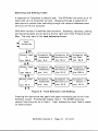
The GPS Navigator &Secure Flight Recorder (GPS-NAV) has three
components: the Flight Recorder containing the GPS Receiver, the LCD
Display, and software for an IBM compatible Personal Computer (PC).
Connection to a Cambridge NAV computer is also provided. The Flight
Recorder can be used with or without the LCD display. It records 9900
GPS fixes. Flight Logs are transferred to a personal computer using a
serial data cable.
Gliding needs different navpoint data than most types of aviation. This is
why GPS-NAV navigation data originates in a PC database program rather
than the GPS-NAV itself. New Version 5 PC software tools make it easy
to construct custom navpoint databases for the GPS-NAV from large
National Databases. Thanks to John Leibacher and many other volunteers,
an amazing source of turnpoint databases can be found at:
http://acro. harvard.edu/SSA/JL/TP/HomePage.htmI
Navpoints are sent to the Flight Recorder using the serial data cable. With
navpoint data in the Flight Recorder, the GPS-NAV display provides
navigation information. The unit can also mark its present location, and
navpoints may be created, edited, and saved in the GPS-NAV database.
Bearing and distance to a waypoint, ground speed, and track are sent to an
attached Cambridge S-NAV or L-NAV. GPS related functions of these NAV
computers are described in their documentation.
Version 5 Firmware Additions and Improvements
This list covers only improvements made since Versions 4.1 and 4.6.
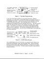
1. Automatic variable rate logging
Logging intervals can change automatically from 2 to 60 seconds. Logging
changes to the minimum interval near the active navpoint. Two minutes of
fast logging is also activated by pressing the ON key. This feature extends
flight logging to 16 long flights. Maximum total flight time is now more
than 120 hours.
GPS-NAV Version 5 Page 3 2/l O/97
2. Task entry from the PC
Up ta 10 tasks (A - .I) can be defined in the PC navpoint database editor.
Tasks are transmitted to the GPS-NAV with the navpoints.
3. Fast scrolling of large Navpoint databases.
Any of the 250 navpoints in the database can be selected in less than 7
seconds. The secret is to tap the UP or DOWN arrow key quickly. This
jumps past 9 navpoints.
4. Simplified Task editing
Task selection, editing, and declaration are now done in one group of
screens. An active task can now be edited. Distance from the beginning of
the task is shown for each intermediate turnpoint. A trial P.O.S.T. task
can be started without declaring it.
5. Simplified Navpoint Editing.
Attribute and ID# are now shown in point editing screens.
6. Improved Circling Wind Algorithm
The circling detection algorithm is now more sensitive and reliable.
7. Error Detection and Correction for Navpoint database.
Some GPS-NAV instruments developed navpoint database errors when
power was cycled rapidly. Critical navigation data is now stored in two
locations. Error detection and correction algorithms ensure reliable
navigation data.
8. Transmission of task data to L-NAV and $-NAV.
GPS-NAV Version 5.0 transmits the active task to an L-NAV or S-NAV.
This makes it possible to compute altitude required to glide home around
an intermediate turnpoint. GPS-NAV V4.8 does not have this feature.
GPS-NAV Version 5 Page 4 2/l 0197
The instrument and its associated PC software are approved by the IGC for
FAI Glider and Motorglider Badge and Record flight documentation. As of
October, 1996, tasks may be declared electronically using the GPS-NAV.
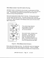
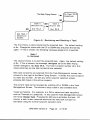
A Walking Tour
The quickest way to learn the Cambridge GPS-NAV is to walk around with
it! Attach a 12 Volt battery (Model 20 & 25), connect the LCD display
with the supplied test cable, and press the LCD display ON key. The LCD
should show a sequence of messages. If it does not, make sure it is
attached to the correct port (GPS Display) on the instrument. You should
also note that the green GPS lamp is on continuously rather than blinking.
This means there is not yet a GPS fix of your present position.
When a GPS receiver is moved to a new site more than 300 miles away
from where it was last used, it can take up to 40 minutes to acquire the
satellite orbital data required for its initial position fix. Also, GPS does
not work indoors. Orient the antenna so it has a good view of the sky.
While waiting for the GPS receiver to wake up and smell the roses, take a
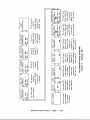
look at the various LCD screens. Screens are arranged in Rows and
Columns. Use the Primary Screen Map on page 2 as your guide. LEFT and
RIGHT arrow keys move to the top row of a new column. UP and DOWN
arrow keys move to new rows within a column, or change information
within a screen.
Pressing the GO key several times always finds the Main Flying Screen.
This is the screen you will use most of the time.
GPS-NAV Version 5 Page 5 2/l O/97
Once a GPS “fix” has been obtained, you can see detailed information in the
set of screens just to the right of GPS Status. Latitude including
hemisphere (North or South) is shown first. Use the DOWN key to see
Longitude, GPS Altitude, Pressure Altitude based on standard atmosphere
(1013 mBar, 29.92” Hg), Sound Level, Estimated Position Error (EPE), Date,
and time (UTC). Time and date come from the satellites and cannot be
edited.
Pressure Altitude comes from a calibrated altimeter sensor within the
GPS recorder. It has better short term stability than GPS Altitude, and is
used for the barograph trace. Sound level is measured with a calibrated
microphone and recorded as part of the Flight Log. The recorded sound
level shows when a motorglider engine is running.
The Cambridge GPS-NAV is optimized for use in a glider moving towards a
waypoint. Those conditions must be simulated to fully understand the
“Navigate to” screen. This is where the walking comes in. To keep things
simple, you will mark your present position as a thermal, walk some
distance away, and navigate back to this position. Here is the sequence:
1.
2.
3.
Return to the “Navigate to” screen by pressing GO.
Move one screen left to the “Mark Thermal” screen.
Press GO to Mark your present position as a Thermal.
The next step is to actually navigate to this marked “Thermal”.
4.
5.
Move to the Mark Thermal screen again.
Press the UP or DOWN key. You will see:
Select
Last Thermal
6.
Press GO again. “Thermal” becomes the active navpoint.
Navigate to
Thermal
Walk away to a distance of at least 500 feet. Turn around and
let the GPS-NAV guide you back to your “Thermal”.
7.
GPS-NAV Version 5 Page 7 2/10/97
You must walk faster than 2 Kts (3kmIhr) to see the Track number and the
Turn Indicator. You will quickly learn to interpret the graphic arrow as
well as the track and bearing numbers.
You can
changes
the date
return to
measure your velocity by pressing the UP key. The Brg. number
to velocity, V, and the first line changes from “Navigate to” into
and time (UTC) the thermal was marked. As always, press GO to
the Main Flying Screen.
This completes the walking tour. The basic concept of screens and use of
GO and arrow keys have been described. Screens are consistent in design,
labelling is clear, and keys always work the same way. This means GPSNAV functions can be mastered by simply trying them. Most users can quit
reading here, install the GPS-NAV, and go flying without further delay.
But, if it is raining, feel free to read on!
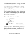
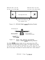
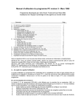
Bearing, Heading, Track, and the Turn Indicator
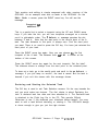
+ Wind, 90”
Figure 3. Definition
of GPS Navigation Terms
Angles are defined relative to Magnetic North. Bearing is defined as the
angle of the line between the glider’s position and the waypoint. Imagine
the shadow of the glider tracing a line on the ground. The angle of this
imaginary line is the glider’s Track. Heading is where the nose of the
glider is pointed. A compass shows Heading. Crosswinds make Track and
Heading different.
GPS-NAV Version 5 Page 8 2/l O/97
The GPS receiver computes its position every 2 seconds. Even though
position is only known for sure to within the Estimated Position Error
{typically about 100 meters), positions determined 2 seconds apart are
very accurate relative to one another. This means the GPS receiver can
measure the glider’s direction of flight (the Track) and its true ground
speed, V, with high accuracy. This is done by calculating the angle
(relative to magnetic north) between two fixes for Track and dividing the
distance between two fixes by time for V.
GPS navigation is simple. It is no longer necessary to worry about glider
Heading as indicated by the compass. Without GPS, the pilot has to guess
the crosswind and then crab into it to fly the desired Track. With GPS,
Track itself is measured accurately, so there is no need to estimate crab
angles, etc. When Track and Bearing are the same, the glider is heading
directly to the waypoint.
The GPS-NAV shows both Bearing and Track in the “Navigate to” screen.
Bearing - Track = Track Error. Positive Track Error means the glider
must turn right to fly towards the navpoint. Glider pilots have little time
for arithmetic while racing. So, the GPS-NAV has a graphic Track Error
Indicator. When the Indicator is centered, the glider is flying directly to
the active navpoint. This is true even with crosswinds. A glance at the
graphic Indicator shows which way and how much to turn. This is much
simpler than remembering a compass Bearing, setting up a compass
Heading, and guessing the required Track.
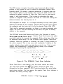
Figure 4. The GPS-NAV Track Error Indicator
When Track Error is less than 5”, only the center vertical bar shows.
For Track Error greater than 45’, the center vertical bar goes away,
followed by the inner segments. GPS Track lags behind the actual glider
track during circling. For this reason, the graphic Track Error Indicator is
switched off during circling flight.
GPS-NAV Version 5 Page 9 2/10/97
It is important to remember that this indicator shows Track rather than
glider Heading. This is especially useful during high wind conditions such
as flight in wave lift. When flying directly into a high wind, the glider
may be almost stationary over the ground. Think how the shadow of the
glider moves over the ground. A small change in Heading makes a big
change in Track. Trust the Indicator!
Navpoint Screens.
The Cambridge GPS-NAV is optimized for competitive and recreational
gliding. Quick navpoint review is a unique feature of the instrument. Most
screens to the right of the “Navigate to” screen are devoted to navpoint
review. Once the desired navpoint has been found, it is always activated
by pressing GO.
It is helpful to experiment with the GPS-NAV as you read this section,
First, load enough navpoints to get the idea. See the section labelled
Waypoint Editing for details. Better yet, load a navpoint database from
the PC software library. Finding and activating navpoints is the same
for all screens.
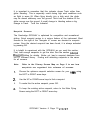
Note:
Refer to the Primary Screen Map on Page 2 to see how
navpoints are organized into columns of screens.
1.
Choose the optimum navpoint selection screen for your ne&Js using
the LEFT or RIGHT arrow keys.
2.
Use the UP or DOWN arrow keys to find a navpoint.
3.
To make this the active navpoint, press GO.
4.
To keep the existing active navpoint, return to the Main Flying
Screen using the LEFT or RIGHT arrow key.
GPS-NAV Version 5 Page 10 2/l O/97
The “Last Point“ screen
The GPS-NAV lets the pilot switch easily between two waypoints of
interest. Here is how it works with navpoints named PARIS and MOSCOW:
The pilot is navigating to PARIS but is interested in MOSCOW.
MOSCOW is selected from any waypoint list and GO is pressed. Now
MOSCOW is active and is shown in the “Navigate to” screen.
PARIS is now stored in the “Last Point” screen just to the right of the
“Navigate to” screen. The pilot can re-activate PARIS from there by
pressing GO.
When PARIS is re-activated, MOSCOW replaces PARIS as the “Last Point”.
It is quick and easy to re-select MOSCOW if desired. But it may take a
long time to fly there!
More about Navpoints
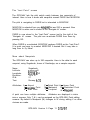
The GPS-NAV can store up to 250 navpoints. Here is the data for each
navpoint, using Sugarbush, home of Cambridge, as a sample navpoint:
Name:
Latitude:
Longitude:
Elevation:
ID #:
Text:
Sugarbush
44OO7.05 N
072”49.61 W
1470 ft.
27
Runway 4/22
Attributes: A - Airport
L - Landable Point
S - Start Point
F - Finish Point H - Home Point
M - Markpoint
R - Restricted Point
T - Turnpoint
W - Waypoint
A point can have multiple attributes. Attributes are displayed in Edit
Point screens. Only T & L can be assigned on the GPS-NAV Point editing
screens. By default a Markpoint (M) changes to W during editing if no other
choices are made.
GPS-NAV Version 5 Page 11 2/l O/97
Attributes control the organization of navpoints into LCD screen lists.
Points with T, S, f, or R attributes are listed in T P: Alphabet and T P:
Distance screens. Points with A, L, M, and W attributes are listed in the
Landpoints screen in order of distance from the present location. This
means the pilot can mark a potential landing field while flying over it.
Later, it can be selected quickly.
Attributes also control other behavior. For example, when the GPS-NAV is
first turned on, the Navigate to screen shows the Home Point (H). if there
is no Home Point, the GPS-NAV displays the navpoint with the lowest ID #.
Editing a Markpoint changes the attribute from M to W. Thanks to Dickie
Feakes, W points can now be shown together with Task points on the PC
display. Marked mountain passes and cois are now easy to visualize.
Remember that the total number of points including Markpoints cannot
exceed 250.
Only points with Turnpoint (T), Start (S), and Finish (F) attributes are
included in the list from which tasks are constructed. Even though you can
navigate to a Thermal, it is not kept in the database and has no ID #.
Markpoints and Thermals show up on navpoint selection lists. But they are
also easy to find in the screens where they have been marked. For
example, suppose 3 points have been marked. The Markpoint screen shows
the next point (#4) which could be marked.
Mark
Point #4
if the UP key is pressed, the screen changes to:
Select
Markpoint #3
Ail the previously marked points may be found this way. In this case,
pressing GO makes Markpoint #3 the active point.
GPS-NAV Version 5
Page 12 2/10/97
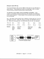
Ground Speed Display and Wind Estimation
The glider’s ground speed (displayed with the label V) replaces Bearing on
the screen where the comment text is displayed. The wind component in
the direction of flight can be estimated from the difference between
indicated airpeed (from the mechanical ASI) and the ground speed. This is
only accurate at low altitude because of the difference between indicated
and true airspeed. If a Cambridge NAV variolglide computer is connected
to the GPS-NAV, true airspeed (TAS) is computed and subtracted from
ground speed. The difference is an accurate measure of the wind
component in the direction of flight. This is displayed on the NAV and
used in its final glide computations.
The ground speed display is especially useful in wave flying. If the glider
is pointed directly into the wind, ground speed may be near zero. If ground
speed decreases when airspeed is increased, the glider is actually moving
backwards over the ground. The Track display will also show this.
GPS-NAV Version 5 Page 14 2/l O/97
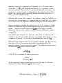
In Edit Point and Create Point screens, pressing GO branches to a second
sequence of 7 detail screens for editing the selected point.
Edit Name
Edit Lat
Edit ID#
Edit Long
Landpoint?
Edit Kiev
Turnpoint?
The starting point is Name. The default name for a freshly created point
is NEW. At the start of editing there is an underline cursor beneath the
first letter of the name. The UP and DOWN arrow keys scroll through all
possible letters for this location. The LEFT and RIGHT arrow keys move
the cursor left and right in the Name, Latitude, and Longitude screens.
For a newly created point, the GPS-NAV assigns the last known GPS
receiver position to simplify Latitude, Longitude, and Elevation entry.
New points are arbitrarily assigned ID numbers starting with 8000.
Markpoints are assigned ID numbers starting with 9000. This makes it
easy to find these classes of points when they are arranged by ID number.
The GPS-NAV assigns an internal, hidden index number for each point.
Thus, two points may have the same Name, ID #, and position without the
GPS-NAV being confused. However, transferring waypoints to the PC
database does require unique ID #s, so it is best to assign a different
number to each waypoint.
These screens also allow Landpoint (L) and Turnpoint (T) attributes to be
assigned for each waypoint. Landpoint means the point is suitable for
landing. The Landpoint attribute makes the point show up in the list of
Landpoints arranged by distance. Turnpoint means the point can be
selected for a task and will show up on the PC screen. If no attributes are
assigned, the point is simply called a Waypoint (W).
Pressing the GO key from the detailed point editing screens stores the
new or edited point in the GPS-NAV database.
GPS-NAV Version 5 Page 17 2/l O/97
Task creation and editing is simple compared with older versions of the
GPS-NAV. As an example, start with no tasks in the GPS-NAV. On the
Edit Task A screen, press the RIGHT arrow key. You will see the
message:
Turnpoint A0
Ih Select v
This is a gentle hint to select a turnpoint using the UP and DOWN arrow
keys. If you take the hint, you will see turnpoints arranged on a circular
scroll in alphabetic order. The * Select v message occupies the slot
between Z and A. Note that the start point is the zero’th point of the A
task. The task distance to this point is always zero. Find the start point
you want. There is no need to press the GO key. You have just selected the
start point of your task.
Press the RIGHT arrow key again. Now you can choose ~1, the first
turnpoint of the A task. The distance from ~0 to Al is shown at the
bottom of this screen.
Press the RIGHT arrow key again for the next turnpoint. Get the idea?
The distance shown is always from the start point to the selected point.
To clear out a task, go to the zero’th point and scroll to the h Select v
message. If you just keep on scrollin’, the task is saved. But the task is
cleared if you exit this screen with this message shown.
Declaring and Starting the Selected Task
The GO key is used to exit Task Selection screens. On the way towards the
exit you must make two choices. The first choice is about Declaring the
task. A declared task has date and time attached to it. The Declared task
is attached to the Flight Log file in the PC. This permits Official
Observers to see if you declared your intentions before takeoff. You may
want to edit a task without declaring or starting it. The GPS-NAV design
is clever enough to give you just the right choices.
GPS-NAV Version 5 Page 19 2/l O/97
Messages and Sounds near Active Navpoints
The GPS-NAV provides extra help near the active waypoint. As the glider
approaches the waypoint, the recorder gives two short beeps, and the
display shows Close to: in place of Navigate to. When the glider gets
nearer the turnpoint, the recorder gives one long beep and the display
changes to Arrival !. The GPS-NAV is silent as the glider leaves the
turnpoint, but the pilot may beep or cheer as the spirit moves. The radius
at which each message appears is configurable. See the PC software
User’s Guide for details.
If the GPS-NAV LCD Navigate to: screen is not visible, the letter M for
Message will appear on the screen. Pressing GO returns to the main
navigation screen where the message Close to: or Arrival! is visible.
Messages and Sounds in Restricted Areas
The GPS-NAV warns the pilot as a restricted area is entered. In the PC
Navpoint database, a point with an R attribute is assigned a radius, a
bottom, and a top altitude. The restricted area is a cylinder with these
dimensions surrounding the R point. Restricted points are listed on the
Landpoints screen in order of distance from the current position.
When the glider enters this area, the GPS-NAV gives 4 short beeps, and the
display shows Restricted 1 in place of Navigate to. While the glider is
inside the circle, the Restricted
! message overrides all other messages
on the Main Flying Screen. Inside restricted space the audio warning is
repeated every 10 minutes.
The GPS-NAV warning happens at the exact boundary of the restricted
area. Careful pilots will choose restricted area dimensions slightly
larger than the actual airspace boundaries.
GPS-NAV Version 5
Page 21
211 o/97
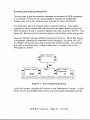
Recording Flights
The GPS-NAV is designed so the Flight Recorder may be used by itself
without the LCD Navigation display. The GPS lamp on the Flight Recorder
flashes whenever the receiver is able to find its position.
Once position is known, flight logging is automatic. It begins when either
horizontal or vertical motion starts. Position, GPS Altitude, Pressure
Altitude, Estimated Position Error, and GPS-derived date and time are
written periodically into the Flight Log. The GPS-NAV keeps a buffer of
fixes at all times. When motion starts, two minutes of pre-flight fixes
are logged. This provides a stable barograph baseline for altitude
measurement. Logging continues for two minutes after motion stops.
GPS-NAV Flight Logs are erased only when new pilot and navpoint data are
transferred to it from the PC. This means pilots can transfer Flight Logs
as often as they please to several different PC’s.
Under new FAI Sporting Code rules, Flight Logs made by the GPS-NAV can
verify FAI badge and record claims. They can also be used in glider
competition to validate flight paths around turnpoints. Pressure altitude
as well as’GPS altitude and position are record.ed. Motorglider engine
noise is also continuously recorded. Therefore, Flight Logs from the GPSNAV can replace photographs and barograph traces for both glider and
motorglider flight validation. Flight Logs also provide useful information
for all stages of glider pilot training.
Version 5 firmware adds two new features to GPS-NAV flight recording:
1. The GPS-NAV Arrival! message and its asociated acoustic warning
are now synchronized with logging. This means you can leave a
turnpoint as soon as you see the message or hear the long beep.
2.
The pilot can select short and long logging intervals in the PC
software. The range is 2 to 60 seconds. The long interval is used far
from the active navpoint. As the glider approaches the arrival radius
of the active navpoint, the logging interval is reduced automatically to
the short value. 15 fixes at the short logging interval begin whenever
the ON key is pressed
GPS-NAV Version 5 Page 22 2/l O/97
Flight Log Security
The design of the Cambridge GPS Navigator and Secure Flight Recorder
guarantees integrity of Flight Logs. Several mechanisms are used. The
first is to append a digital “Signature” to each Flight Log. If the Flight Log
is modified in any way, its “Signature” changes in a way that is virtually
impossible to decipher.
The Cambridge GPS-NAV system permits Flight Logs to be shipped by
diskette or even by modem or Internet from one site to another without
risk of tampering or alteration. This means it is practically impossible to
cheat by supplying contest officials or badge and record issuing
authorities with altered, bogus flight logs.
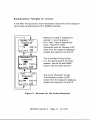
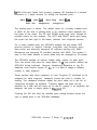
GPS-NAV Recorder Sealing
The system described in the previous section prevents alteration
Flight Log from the moment it is transferred to the PC from the
Recorder. However, without further measures, it is easy to cause
Flight Recorder to contain a bogus, altered Flight Log. This could
by taking the following steps:
of a
Flight
a GPS
be done
1.
The pilot flies the task but misses one turnpoint.
2.
The Flight Log is sent to the PC.
3.
The Flight Log is modified within the PC to show the pilot actually
going around the turnpoint.
4.
The data file is converted to the standard, NMEA-0183 format used
for data transmission between the GPS receiver “engine” and the
GPS-NAV Recorder memory.
5.
The modified Flight Log is sent to the GPS-NAV Recorder memory
using the wires from the GPS receiver “engine”.
6.
The modified Flight Log is sent back to the PC. The GPS-NAV “signs”
the modified Flight Log as it is uploaded to the PC.
G P S - N A V 5 P a g e 2 3 2/l O/97
The Cambridge GPS-NAV prevents this kind of Flight Log alteration by
permanently sealing the Recorder box and, therefore, the critical
connection between GPS receiver “engine” and Flight Recorder memory.
Removing the Model IO GPS-NAV top cover breaks this seal. Removing the
Model 20 or 25 GPS-NAV main cover also breaks this seal. The Waypoint
database and Flight Log are lost. Replacing the cover does not replace the
seal. The permanent factory electronic seal can be replaced only by
returning the GPS-NAV to Cambridge Aero Instruments.
The status of the GPS-NAV Recorder seal is shown at power-on. See the
following section for details of the power-on message sequence. When a
GPS-NAV cover has been removed, the message:
is replaced by:
GPS Recorder
Sealed
GPS Recorder
Not Sealed
The GPS-NAV will still function. However, Flight Logs will not be secure
and will fail the electronic Validation test. This means that an Official
Observer will be required to verify independently that the flight recording
has not been altered.
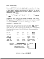
Power-on Messages
A series of messages is shown when the GPS-NAV is first turned on. They
show revision levels of Recorder and LCD display firmware, Pilot’s name,
glider identifier, Recorder serial number, Recorder seal status, and
battery status. Some messages are also shown whenever the ON key is
pressed. Pressing GO stops the display of messages.
Recorder serial number and factory security code are assigned by the
manufacturer. They cannot be altered. The pilot’s name and glider
identifier are supplied by the pilot using the PC. See the PC Software
User’s Guide for details.
G P S - N A V 5 P a g e 2 4 2/I O/97
GPS-NAV Model 10 Battery Status and Battery Charging
The Model 10 GPS-NAV has a self-contained 12 volt, 2.0 Amp/Hour GelCell Lead Acid battery. The Model IO GPS-NAV draws about 220mA. A
fully charged battery reads above 12.7 volts. Normally, this will power
the Recorder for more than 8 hours. An old battery or cold weather will
reduce this time. When the battery drops below 11 volts, it is discharged.
The GPS-NAV shuts itself off when the battery drops below 9.5 volts.
The glider main battery can be connected to the Model 10 GPS-NAV. Power
is drawn from the battery with the higher voltage. This improves
reliability if the GPS-NAV battery fails. When the external, glider battery
has a higher voltage than the internal battery, External Battery voltage is
also displayed in the message sequence. The Recorder will work with
external power even when the internal battery fuse has failed.
The GPS-NAV is supplied with a 12 Volt 300mA battery charger. With the
GPS-NAV turned off, about 12 hours are required to completely re-charge
a discharged battery. Since overcharging will shorten battery life, the
charger should not be connected for longer periods. A typical discharged
battery will charge at more than 300 mA, while a charged battery takes
less then 150 mA. Charging current is shown in the power-on message
sequence when the charger is connected. If the Battery charge lamp fails
to blink or the charge current shown on the LCD display is zero, check
charger wiring and the battery fuse under the bottom cover.
G P S - N A V 5 P a g e 2 5 2/l O/97
The backup battery preserves the Flight Log even when power to the
Recorder is turned off. The output of a new backup battery is about 3
volts, and it should last about 5 years. When its output falls below 2.0
volts, the backup battery should be replaced.
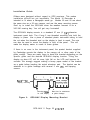
Main battery
Yuasa type NP-12
12 Volt 2.0 Ah
Battery fuse
2 Amp Slow-Blow
Recorder fuse
2 Amp Slow-Blow
4+ Backup battery
Lithium coin cell
type BR-2325
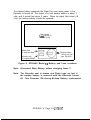
Figure 8. GPS-NAV Model IO Battery and Fuse Locations
Note:
Disconnect Main Battery before changing fuses !!
Note: The Recorder seal is broken and Flight Logs are lost if
the backup battery is removed with the Recorder turned
off. Turn Recorder ON during Backup Battery replacement.
GPS-NAV 5 Page 26 2/l O/97
GPS-NAV Model 20 & 25 Backup Battery and External Supply
The Model 20 & 25 GPS NAV rely on the
power during operation. A lithium back-up
flight recordings when power is removed.
electronic seal which prevents tampering.
battery drops below 2.0 volts, it should be
Glider’s battery for electrical
battery is used to preserve
It also preserves the permanent
When the output of the lithium
replaced.
The lithium battery is located under the flat plate antenna on the GPSNAV Model 20. On the GPS-NAV Model 25, the battery is under the side
cover plate.
Note: Before replacing the lithium battery, be sure to turn the
GPS-NAV on. This will prevent the permanent electronic seal
from being broken.
Note: It is important to keep power supplied to the Model 20 &
25 GPS-NAV during Flight. For gliders with 2 batteries,
switching between batteries must be done quickly to avoid
removal of power to the GPS-NAV. We recommend two separate
b a t t e r y s w i t c h e s . This way, battery #2 can be connected before
B a t t e r y #I i s d i s c o n n e c t e d .
The Model 20 & 25 GPS-NAV’s are suppplied with a wall mounted power
supply. (12 Volts DC @ 300 mA) This unit runs the GPS-NAV during
transfer of data to or from the PC. Note that the outer contact on the
power supply connector is Positive. See the Specifications section for
details and wire color codes for other connections to the GPS-NAV.
G P S - N A V 5 P a g e 2 7 2/l O/97
Troubleshooting
The following problem/answer (P./A.) list may help locate the source of difficulties in
installation and use of the GPS-NAV:
P.
The GPS-NAV Model 10 Recorder will not turn on using its own power switch.
A.
Its battery is completely discharged or an internal fuse is blown.
P.
The GPS-NAV Model 10 runs with an external battery but not with its internal battery.
A.
The battery fuse is blown. This can happen if a high capacity charger has been used, if
the charging leads have been shorted together, or if the charger is of the wrong polarity.
We strongly recommend use of the charger supplied by Cambridge.
P.
The GPS-NAV Model IO turns itself off soon after being turned on.
A.
Its internal battery is almost completely discharged. The GPS-NAV shuts down at 9.5 V.
P.
The GPS-NAV Recorder cannot be turned on from the display unit.
A.
The display cable must go to the “GPS Display” port on the Recorder. The cable may
have been connected to the “NMEA-0183” port. No damage results from this.
The cable may also be defective. See the Installation Guide for the correct way to put
connectors on the flat cable. Check for proper operation using the test cable.
P.
The display lights up, but shows “Navigate to: No Points!“.
A.
Either there are no waypoints in the Recorder database, or the cable between display and
Recorder is defective. To check for a bad cable, see if the UTC clock is running. The
clock is shown in the ” Latitude” screen list. The internal GPS “engine” keeps time even
when there are no visible satellites. If the clock is running, the GPS “engine” and
Recorder are functioning, and the Recorder/Display cable is OK.
G P S - N A V 5 P a g e 2 8 2/l O/97
P.
The GPS Recorder always shows zero satellites. That is, no satellite annunciators are
visible in the ” Navigate to” screen, and the Status screens show O/n on the top line.
A.
If the GPS receiver is OK, this means no signals are being received from the antenna.
There are several possible reasons for this:
1.
The 1575 MHz GPS signal does not pass through buildings, so GPS doesn’t work
indoors.
2.
The coaxial antenna cable may be defective. Check reception with the antenna
attached directly to the Recorder. Twist-on BNC connectors are not as reliable as
crimp-on types. Check continuity of the coaxial cable center conductor with an
ohmmeter.
3.
The antenna may be defective. This is a rare occurance.
P.
The GPS lamp on the Recorder never flashes. One or two satellites are visible.
Satellite Status screens show signal strengths below 40.
A.
The antenna is in a poor location. Antenna location is critical to performance. GPS
signals have no problem going through the fiberglass used in a glider fuselage skin.
Plexiglass canopies are also transparant to GPS signals. However, thick fiberglass such
as a spar will cause problems. A carbon fiber fuselage will block the GPS signal. Also,
a metal frame, panel or even pushrods may cause problems.
P.
The Recorder always takes a long time to acquire satellites.
A.
If the Recorder is turned on before the antenna is attached, or in a location where the sky
is obscured, it may go into “search the sky” mode. This takes up to 40 minutes. Turn
power off and on again when signals are available. This will shorten acquisition time.
P.
The Recorder switches between 20 and 30 navigation. Flight recordings show high EPE.
Track (Trk) and ground speed (V) numbers are erratic.
A.
The antenna is not working properly. The receiver will normally acquire between
6 and 8 satellites during flight. It should usually see more than 5 satellites. If this is
not so, check the antenna mounting location.
G P S - N A V 5 P a g e 2 9 2/l O/97
P.
The graphic Track Error Indicator and the visual location of an active waypoint do not
agree. The Indicator seems to guide me in the wrong direction.
A.
This is normal! You are seeing the effect of wind. The glider’s heading will crab into the
wind. This points the nose of the glider away from the goal. In a strong headwind,
the Indicator will be very sensitive because it relates to Track and not Heading.
P.
GPS Recorder distances are slightly different from those calculated by the PC software.
A.
This is normal. The PC software uses the Great Circle method. The GPS Recorder uses
rectilinear coordinates . This gives fast updates and is optimum for in-flight navigation.
These numbers should not be used for calculation of badge and record distances.
P.
Distances shown by the GPS Recorder are vefv different from map distances.
A.
The maximum distance which can be displayed on the GPS Navigator is 1400 NM or
2700 Km. The Recorder and the map may use different units for distance. The Recorder
is configured by the PC software for one of 4 different units systems.
They are:
Nautical Miles, feet, knots
Kilometers, meters, kilometers/hr
Kilometers, feet, knots
Statute miles, feet, knots
G P S - N A V 5 P a g e 3 0 2/l O/97
Specifications
Model IO with
mounting bracket
6.2” (158 mm) long, 6.2” (158 mm) wide
3..1” (79 mm) height
Model 20 with
GPS Antenna
4.7” (120 mm) long, 2.7” (68 mm) wide
2.3” (84 mm) high
Model 25 with
BNC Connector
5.5” (140 mm) long, 2.7” (68 mm) wide
1.9” (74. mm) high
LCD Display
and control unit
2.6” (66 mm) height and width
0.47” (12 mm) in front of instrument panel
0.80” (20 mm) behind instrument panel
Fits standard 57 mm panel opening.
Model 10
3.6 Ibs (1.64 Kg)
Model 20 or 25
0.8 Ibs (0.36 Kg)
LCD Display
and control unit
0.35 Ibs (0.15 Kg)
Model 10
Internal 12 volt or external 12-14 volt battery
Current drain 220 mA with 7 LCD display
Model 20 or 25
External 12-14 Volts or power supply
Current drain 160 mA with 1 LCD display
LCD display
Second seat LCD adds 10 mA to current drain
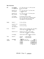
Fuses:
Model 10
Recorder:
Battery:
Voltage:
Indicator
Model ?O
1 flash,30 second repeat
2 flashes, 10 second repeat
3 flashes
4 flashes
5 flashes
6 flashes
Size:
Weight:
Power:
2 Amp Slow-Blow
2 Amp Slow-Blow
GPS-NAV 5 Page 31
v < 10.75
10.75
11.25
11.75
12.25
12.75
2/l o/97
<V
<V
c v
<V
<V
c
<
<
<
<
11.25
11.75
12.25
12.75
13.25
Charger/Power Supply
12 volt DC, 300 mA, Center pin negative
Charge:
LED
0 flashes
1 flash
2 flashes
3 flashes
Model 10
Octc50mA
50~ I < 150mA
150cIc250mA
250 c I < 350 mA
Note: Charge current flash is longer than voltage flash
Logging Interval:
4.seconds minimum up to 32 seconds; PC configurable
Maximum Flight time:
11 .hours at 4 seco.nds logging interval
Altimeter:
Temperature compensated, piezoresistive sensar
Range 36,000 feet.
Resolution 30 (10 meters) feet at sea level.
Means of Propulsion (mop)
(Engine Run) detector
Calibrated microphone
G P S - N A V 5 Page 32 2/l O/97
Installation Guide
Gliders were designed without regard to GPS receivers. This makes
installation difficult but not impossible. The Model 10 Recorder is
intended to fit where a Barograph would go. Models 20 and 25 are about
the same size as a 35 mm camera, and use the same mounting screws.
Don’t try to install the GPS-NAV when the weather forecast is for a
300 KM soaring day. You will get very frustrated!
The GPS-NAV display mounts in a standard 57 mm (2 l/4”) diameter
instrument panel hole. The 4 long 3 mm threaded mounting nuts hold the
display in place. Use a piece of standard plastic instrument tubing to hold
the nut when the threaded stud on the display is hard to reach. The nuts
can also be used to mount the display in front of the panel. This will
make the display easier to reach in some gliders.
If there is no room in the instrument panel, the special bracket supplied
by Cambridge mounts the display to the canopy rail or other parts of the
glider cockpit. There are many ways to bend this bracket depending on the
specific glider and the desired GPS-NAV display location. Tilting the
display up about IO” will let more light fall on the LCD and improve its
contrast. We strongly suggest making a heavy paper model of the bracket
as a guide before bending the actual aluminum part. The bracket can be
attached to to glider fuselage with several 3 mm (#4) self-tapping
screws.
*oo*
Cambridge P/N FA-253
Bend Line for
_ display mounting
t’
4
Mounting tioies
for LCD dispiay
Figure 9.
/
Bend line for attachment
to glider fuselage
GPS-NAV Display Mounting Bracket
G P S - N A V 5 P a g e 3 3 2/l O/97
The GPS-NAV Model 10 mounting system consists of the black painted
Mounting Bracket (P/N FA-245) and the Backup Plate (P/N FA-246).
Attach so the glider fuselage part is sandwiched between bracket and
Backup Plate. We have personally done more than 100 different
installations, so contact us for advice and psychological counseling.
The GPS-NAV Model 20 has a built-in flat plate antenna covered by a black
plastic radome. The antenna must have an unobstructed view of the sky.
there are three favored locations for the model 20:
1.
On or under the instrument panel top cover. Mount the GPS-NAV as
close as possible to the canopy. It is OK to put the unit under the
cover as long as it is not constructed of carbon fiber or metal.
2.
In the same location as your obsolete 35 mm turnpoint camera .
3.
Behind your head near the top of the fuselage. This works when the
top of the fuselage is not made of carbon fiber. GPS signals will
not pass through people, so position the antenna above your head.
The GPS-NAV Model 25 is for desperate pilots with impossible gliders. It
combines the small size of the Model 20 with the separable antenna of the
Model IO.
Note that the antenna mounting bracket supplied with the Model 10 and 25
has mounting hoies which match microphone bracket mounting holes in
many gliders. The Cambridge difference is in the little details!
G P S - N A V 5 P a g e 3 4 2/10/97
Bend this end if you use
the hole on the case bottom
Bend this end if you use
the hole on the case edge.
l
0
l
l
l
l
l
0
0
Cam bridge P/N FA-264
;2
\ _’
/
Bend lines defined by f!
close spaced holes
F i g u r e 1 0 . G P S - N A V M o d e l 20/25 M o u n t i n g B r a c k e t
GPS Recorder case
Note orientation of
mounting bracket recess
q/4-20 Plastic ”
mounting screw
Figure 11.
Detail view showing anti-rotation
recess in Model 20125 M o u n t i n g B r a c k e t
The Model 20125 mounting bracket lets the pilot mount these GPS
Recorders in an astonishing variety of ways. The bracket can be bent
(only once !) by hand using the pre-drilled line of holes. Note that the
two ends are not the same. Use the narrow end with the Model 25 on the
side of the cockpit. The Model 20 uses the wide end in most situations.
G P S - N A V 5 P a g e 3 5 2/l O/97
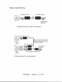
Power Cable Wiring
There are 2 GPS-NAV cables for which the pilot needs to know the wiring.
These are the power cable and the NMEA-0183 connection to an S or L-NAV
or other piece of equipment using real-time GPS data. It is vital that the
cable connectors be attached with the correct orientation. Please refer to
the diagrams shown be!ow.
Power to the Model IO is supplied through the red (+) and black (-)wires in
the 4-wire cable. Note: Use Ferrite RFI Bead on the power cable.
Model 20/25 power control is more complex. Un-switched power (using
the Red wire) means the GPS-NAV is turned on as soon as power is applied.
The GPS-NAV disptay ON switch is not used. You must use this connection
if the GPS-NAV is to be used without its LCD display and without
connection to a Cambridge L-NAV.
Switched power (using the Green wire) means the Model 20/25 GPS-NAV
responds to the ON switch. Power may also be slaved to a Cambridge
L-NAV. When the L-NAV is turned on, the GPS-NAV turns on automatically.
When the L-NAV is turned off, the GPS-NAV waits 30 seconds and then
turns itself off.
Wire color
Yellow
Green
Red
8lack
Port Name
Pin 1
Pin 2
Pin 3
Pin 4
12-14 Volt
Model IO
---__
___--
Switched
+12 Volt
Power
Ground
12-14 Volt
Model 20125
Power
Ground
Power Cable
Orientation
Switched
+12 Volt
Un-switched Power
+12 Volt
Ground
Black’wireg
“Barrel” connector, 12 VDC
Un-switched, Outside Positive
GPS-NAV 5 Page 36 2/l O/97
,