1
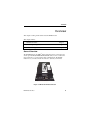
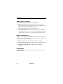
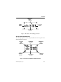
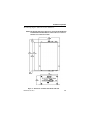
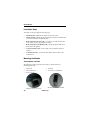
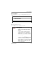
iR1200 Rugged Modem
iR1200 GPS-Enabled Modem
Installation Guide
Table of Contents
Table of Contents
Table of Contents .............................................................................................1
FCC Compliance ..............................................................................................1
Before You Begin Installation .........................................................................3
Box Contents:.................................................................................................3
Required Installation Components .................................................................3
Vehicle Installation.....................................................................................3
Stationary Installation ................................................................................4
Required Accessories .......................................................................................5
Introduction ......................................................................................................7
Welcome to Nextel ......................................................................................7
Using This Guide........................................................................................7
Nextel Coverage.......................................................................................7
Nextel Customer Care..............................................................................8
Overview ...........................................................................................................9
General Overview...........................................................................................9
Modem Operating Modes.............................................................................10
Modem Configurations.................................................................................10
iR1200 Modem .........................................................................................10
iR1200 GPS-Enabled Modem...................................................................11
Installation Preparation.................................................................................13
iR1200 Modem
Before You Start Installing...........................................................................13
Installation Planning.....................................................................................13
Planning Modem Location .......................................................................14
Modem Dimensions .............................................................................14
Planning Antenna Location ......................................................................16
Planning Cable Layout.............................................................................16
Serial Cable Routing ............................................................................17
Installation Tools......................................................................................17
Vehicle Installation.........................................................................................19
Installation Steps ..........................................................................................20
Mounting the Modem...................................................................................20
Select Modem Location ............................................................................20
Mount the Modem.....................................................................................21
Mounting the Antenna(s)..............................................................................21
Approved Antennas...................................................................................22
Select Antenna Location ...........................................................................22
Mount the Antenna(s) ...............................................................................22
Mount GPS Antenna (optional)............................................................23
Route and Connect Cables............................................................................23
Approved Cable........................................................................................23
Route and Connect Power Cable..............................................................24
Route and Connect Ignition Cable ...........................................................26
Approved Cable....................................................................................26
Route Cable ..........................................................................................26
Connect Antenna Cable............................................................................27
Connect Data Cable .................................................................................27
Table of Contents
Stationary Installation ...................................................................................29
Installation Steps ..........................................................................................29
Mounting the Modem...................................................................................30
Select Modem Location ............................................................................30
Mount the Modem.....................................................................................30
Mounting the Antenna(s)..............................................................................31
Approved Antennas...................................................................................31
Select Antenna Location ...........................................................................32
Mount the Antenna(s) ...............................................................................32
Mount GPS Antenna (optional)............................................................32
Route and Connect Cables............................................................................34
Approved Cables ......................................................................................34
Connect Power Cable...............................................................................34
Connect Antenna Cables ..........................................................................35
Connect Data Cables................................................................................35
Verifying Installation .....................................................................................37
Powering Up the Modem..............................................................................37
Powering Up – Vehicle Installation .........................................................37
Powering Up – Building Installation........................................................38
Communication Indicators ...........................................................................38
Packet Data ..............................................................................................40
Circuit Switched Data ..............................................................................40
Troubleshooting..............................................................................................41
Common Problems .......................................................................................41
Diagnostic Port.............................................................................................44
iR1200 Modem
HyperTerminal Setup ...................................................................................45
Diagnostic Menu ......................................................................................47
Unsolicited Firmware Updates ................................................................51
Safety Notice ...................................................................................................55
Safe and Efficient Operation Guidelines ......................................................55
Exposure to Radio Frequency Energy ..........................................................55
Medical and Personal Electronic Devices ....................................................55
Pacemakers ..............................................................................................55
Hearing Aids ............................................................................................56
Other Medical Devices .............................................................................56
Interference with Other Electronic Devices..................................................56
Copyright and Trademark ............................................................................57
Index................................................................................................................61
IMPORTANT!
Please Read Safety Notice on Page 55
before using the iR1200 Modem.
Last Updated
RFM-4000-5015 Rev 1
May 2003
Table of Contents
Table of Figures
Page
Figure 1 – iR1200 GPS-Enabled Modem
9
Figure 2 – Rear Panel of iR1200 Rugged Modem
11
Figure 3 – Rear Panel of iR1200 GPS-Enabled Modem
11
Figure 4 – Dimension of iR1200 GPS-Enabled Modem
15
Figure 5 – iR1200 Installation Wiring Diagram (Vehicle)
24
Figure 6 – Modem Power Wiring Diagram (Level 1)
25
Figure 7 – Modem Power Wiring Diagram (Level 2)
26
Figure 8 – iR1200 Installation Wiring Diagram (Stationary)
34
Figure 9 – iR1200 Front Panel Layout
39
iR1200 Modem
FCC Compliance
FCC Compliance
DECLARATION OF CONFORMITY
Per FCC CFR 47 2.989
Responsible party name:
Address:
eLutions, Inc.
5905 Breckenridge Parkway
Suite F
Tampa, FL 33610
1-800-836-9909
Phone number:
Hereby declares that the product:
Product name:
Model Number:
iR1200 GPS-Enabled Modem
4000-C5-RFM
Product name:
Model Number:
iR1200 Rugged Modem
4100-C5-RFM
Conforms to the following regulation:
FCC Part 15, subpart B
FCC Part 90, subpart S
Class B Digital device
Date:
May 16, 2003
Note: This equipment has been tested and found to comply with the limits
for a Class B digital device, pursuant to part 15 and 90 of the FCC Rules.
These limits are designed to provide reasonable protection against
harmful interference in a residential installation. The equipment generates,
uses and can radiate radio frequency energy and, if not installed and used
in accordance with the instructions, may cause harmful interference to
radio communications. However, there is no guarantee that interference
will not occur in a particular installation.
If this equipment does cause harmful interference to radio or television
reception, which can be determined by turning the equipment off and on,
the user is encouraged to try to correct the interference or by one or more
of the following measures:
-- Reorient or relocate the receiving antenna.
-- Increase the separation between the equipment and receiver.
-- Connect the equipment into an outlet on a circuit different from that to
which the receiver is connected.
-- Consult the dealer or an experienced radio/TV technician for help.
RFM-4200-5015 Rev1
1
iR1200 Modem
2
nextel.com
Before You Begin Installation
Before You Begin Installation
!
Before you begin installing the iR1200 Rugged
Modem or the iR1200 GPS-Enabled Modem, you
must obtain the required installation accessories and
download the Administrators Guide.
For a list of approved accessories, consult the Accessories Table on page 5.
To order the required installation accessories, and the Administrator’s Guide,
contact your sales representative, technology administrator or designated field
care representative.
Box Contents:
The iR1200 modem ships with the following:
•
iR1200 Modem
•
Installation Guide
•
Quick Reference Guide (for operators/end users)
•
Warranty Card
Required Installation Components
The following table lists the items that are required to successfully install your
modem:
Vehicle Installation
•
Approved Cellular Antenna
•
Vehicle Power Harness
RFM-4200-5015 Rev1
3
iR1200 Modem
•
Data Cable for computer (laptop/MDT)
•
Approved GPS Antenna (iR1200 GPS Enabled Modem
only)
•
Data cable for GPS (iR1200 GPS-Enabled Modem)
•
4 screws
Stationary Installation
•
Approved Cellular Antenna
•
AC Power Adapter
•
Data Cable for computer (laptop/MDT)
•
4 screws
Use only an approved antenna. Unauthorized
antennas, modifications or attachments could
impair call quality, damage the modem, or result in
the violation of FCC mandates.
4
nextel.com
Required Accessories
Required Accessories
The following table lists the required accessories that have been approved for
use with the iR1200 Rugged Modem and the iR1200 GPS-Enabled modems.
Please contact your Nextel sales representative or visit
www.elutions.com/wireless to order these items.
Part No.
Description
5000-C5-RFM
Mag Mount Cellular Antenna
5030-C5-RFM
Mag Mount GPS Antenna
5100-C5-RFM
Vehicle Power Harness
5200-C5-RFM
AC Power Adapter (standard temperature)
RFM-4200-5015
RFM-4200-5015 Rev1
Administrator’s Guide
5
iR1200 Modem
6
nextel.com
Introduction
Introduction
Welcome to Nextel
Thank you for purchasing the Nextel iR1200 modem. This modem is designed
to work specifically within the iDEN network. Once installed and configured,
the iR1200 modem provides you with wireless data communications.
This chapter includes:
Using This Guide
Page 7
Nextel Coverage
Page 7
Nextel Customer Care Information
Page 8
Using This Guide
This guide provides instructions for the installation of the iR1200 Rugged
Modem and the iR1200 GPS-Enabled Modem.
Nextel Coverage
For details on Nextel digital cellular and data coverage, visit nextel.com.
NOTE: Transmission and reception speed may vary, based on your
relative position within the coverage area. If you are in a marginal
location (close to the border of the coverage area), the throughput
of your modem during data transmission may be affected.
RFM-4200-5015 Rev1
7
iR1200 Modem
Nextel Customer Care
For domestic customer care issues, including installation, technical support, or
to order accessories contact your technology administrator or designated field
care representative.
When you call, please have a detailed description of your problem. To provide
you with fast and quality support, our Customer Care representative may ask
for the following:
•
Computer operating system (Windows 95/98/NT/2000/CE).
•
Version of the operating system (e.g. NT 4, Windows 95 Version B, CE
2.1, etc.).
•
Information regarding the modem (most can found on the diagnostic
menu).
•
Geographic location of use.
•
IMEI Number
•
SIM ID Number
•
Account Number
8
nextel.com
Overview
Overview
This chapter contains general details about the iR1200 modem.
This chapter includes:
General Overview
Page 9
Modem Operating Modes
Page 10
Modem Configurations
Page 10
General Overview
The iR1200 Modem is an iDEN data modem that consists of a modem card
and an optional GPS (iR12000 GPS-Enabled Modem) receiver, contained in a
rugged enclosure, to provide wireless data communications. The iR1200
modem is easy to mount, whether in a mobile or stationary environment.
Figure 1. iR1200 GPS-Enabled Modem
RFM-4200-5015 Rev1
9
iR1200 Modem
Modem Operating Modes
The iR1200 provides the following data connection modes:
•
Packet Data: A wireless modem connection used for accessing the
Internet, sending and receiving e-mail, and transferring small files over the
packet data network using standard IP protocols.
Data is sent in packets (blocks) of data at high speed.
•
Circuit Switched Data: A wireless modem connection for sending and
receiving data (faxes, files, etc.) over the circuit-switched cellular channel,
providing a direct point-to-point connection with the destination device.
Modem Configurations
Nextel offers two models of the iR1200 Modem. Both are designed to provide
wireless communication for rugged environments. The distinction between the
two models is the optional GPS feature.
The iR1200 modem can be purchased with the following configurations:
•
iR1200 Modem (Base Model) - Available in bulk or individual packaging
•
iR1200 GPS-Enabled Modem - Available in bulk or individual
packaging
iR1200 Modem
The following diagram displays the components that exist on the rear panel of
the iR1200 Modem.
10
nextel.com
Overview
Ignition Sense /
Bypass
Connector
Modem
Serial Data
Connector
12VDC Power
Connector
Modem Antenna
Connector
Figure 2. Rear Panel of iR1200 Rugged Modem
iR1200 GPS-Enabled Modem
The following diagram shows the components that exist on the rear panel of the
iR1200 GPS-Enabled Modem.
GPS Serial
Data
Connector
Modem
Serial Data
Connector
GPS Antenna
Connector
Modem Antenna
Connector
Ignition Sense /
Bypass
Connector
12VDC Power
Connector
Figure 3. Rear Panel of iR1200 GPS-Enabled Modem
RFM-4200-5015 Rev1
11
iR1200 Modem
12
nextel.com
Installation Preparation
Installation Preparation
In this chapter, you will learn how to begin installing your iR1200 modem.
This chapter includes:
Before You Start Installing
Page 13
Installation Planning
Page 13
Planning Modem Location
Modem Dimensions
Page 14
Page 14
Planning Antenna Location
Page 16
Planning Cable Layout
Page 16
Serial Cable Routing
Page 17
Installation Tools
Page 17
Before You Start Installing
Only experienced technicians familiar with installing similar types of hardware
equipment should install the modem. For safety and to avoid damage to the
modem or vehicle wiring, the installer should have knowledge of the following
subjects.
•
Automotive wiring (if applicable)
•
Vehicle cable routing (if applicable)
•
Antenna location
Installation Planning
Planning is the key to a quick and simple installation. Before drilling holes or
running wires, you should inspect the vehicle or area of the building to
RFM-4200-5015 Rev1
13
iR1200 Modem
determine how and where you intend to mount the modem, antenna and
accessories. (See Required Installation Components listed on page 3).
Planning Modem Location
Factors to consider when planning for the location or placement of your iR1200
modem:
•
Easily Accessible – You should allow easy access to the modem (for
troubleshooting purposes).
•
Easily Visible – You should allow a clear view of the modem’s LED
indicators.
•
Proximity of the Cables – The distance between connections affects
performance, especially the distance between the modem and antenna. The
shorter the distance between these components, the better the signal.
(Please refer to the antenna’s Safety Warranty for proper installation
of modem and antenna.)
•
Environment Considerations:
!
- Heat - Placing the modem, antenna or cables near
a heat source can cause several problems,
including radio interference. Select a location away
from a source of heat and make sure the modem
has at least a 1-inch clearance on all sides for cool
air to circulate.
- Wetness – The modem should not be mounted in
an area where it would be directly exposed to
water.
- Direct Sunlight – The modem should not be
mounted in direct sunlight.
Modem Dimensions
Consider the size of the modem. Will the modem fit in the area where you want
to perform the installation?
14
nextel.com
Installation Preparation
The following diagram outlines the modem’s dimensions:
NOTE: This diagram depicts the dimensions of both the iR1200 Rugged
and iR1200 GPS-Enabled Modems and should not be used as a
template for mounting the modem.
Figure 4 – Dimensions of iR1200 GPS-Enabled Modem
RFM-4200-5015 Rev1
15
iR1200 Modem
The following table describes the overall dimensions of the iR1200 modem.
Component
Dimension
Overall dimensions from connector to
connector
7.86in. [199.69mm]
End panel to end panel
7.09in. [180.14mm]
Width (including mounting tabs)
5.04in. [128.02mm]
Width of enclosure
4.04in. [102.62mm]
Height of enclosure
2.20in. [55.88mm]
Planning Antenna Location
Factors to consider when planning for the location or placement of the antenna:
•
Choose a location with easy access to cable routing to ease the process of
connecting the antenna to the modem.
•
In vehicle installation, mount the modem antenna on the center of the
outside trunk for optimum signal reception.
•
In a stationary (building or desk) environment, position the GPS antenna
where it has a direct line-of-sight to the sky. In some cases, this can be
accomplished by placing the antenna adjacent to a window. In most cases
it will require mounting outside of the building.
Planning Cable Layout
Once you have chosen the location of the modem and antenna and before the
installation, layout the cables to determine:
•
If the cables can reach the modem and antenna.
•
If the distance between components is adequate and allows you to make
adjustments to receive a better signal. (Please refer to the manufacturer’s
installation manual for safe installation of your antenna).
16
nextel.com
Installation Preparation
•
If there are kinks or bends in the cable or obstructions in the vehicle that
could affect routing.
Serial Cable Routing
Serial cable routing is the most important factor to ensure a trouble-free
operation. The serial cable should be as stable as possible (e.g., it should
experience little or no movement and have very few or no bends or kinks).
NOTE: The majority of the problems occur because of serial cable failure.
Installation Tools
You will need these tools to install the iR1200 modem.
•
Portable Drill
•
Hammer
•
Center Punch
•
Connector Crimp tool
•
Four #10 self-tapping sheet metal screws
•
Phillips Screwdriver
RFM-4200-5015 Rev1
17
iR1200 Modem
18
nextel.com
Vehicle Installation
Vehicle Installation
In this chapter, you will learn how to install your iR1200 modem and antennas
in a vehicle.
This chapter includes:
Installation Steps
Page 20
Mounting the Modem
Page 20
Select Modem Location
Page 20
Mount the Modem
Page 21
Mounting the Antenna(s)
Page 21
Approved Antennas
Page 22
Select Antenna Location
Page 22
Mount the Antenna
Page 22
Mount the GPS Antenna
Page 23
Route and Connect Cables
Page 23
Approved Cable
Page 23
Route and Connect Power Cable
Page 24
Route and Connect Ignition Cable
Page 26
Connect Antenna Cable
Page 27
Connect Data Cable
Page 27
RFM-4200-5015 Rev1
19
iR1200 Modem
Installation Steps
To install, you must complete the following steps:
•
Mount Modem – Mount the modem in the desired location.
•
Mount Antenna – Mount the antenna using the instructions included with
your selected antenna’s installation guide.
•
Route and Connect Power Cable – route the power cable from modem
to the vehicle’s power supply (ignition switch).
•
Route and Connect the Ignition Cable – Route the ignition cable from
the modem to the ignition.
•
Connect Antenna Cable – Connect cable to the mounted modem and
antenna.
•
Connect Data Cable – Connect the data cable from the modem to the
mobile device.
Mounting the Modem
Select Modem Location
The following describes typical locations that you should consider for
mounting the modem:
•
•
•
Under seat
Under dashboard
Center console
Mounted on side of console
20
•
•
In trunk
In accessory compartment
Mounted on side wall of trunk
nextel.com
Vehicle Installation
Mount the Modem
The following table lists the steps for mounting the iR1200 data modem in a
vehicle.
1 Determine a convenient location in the vehicle.
2 Use the iR1200 modem and mark the positions of the holes
on the mounting surface.
3 Drill the holes in the marked location.
4 Mount the unit using the #10 sheet metal screws.
Mounting the Antenna(s)
The location of the antenna should be chosen carefully.
!
Important things to consider when installing the
antenna equipment.
•
Installation of recommended equipment must be
installed in accordance with Nextel’s installation
instructions.
•
To assure compliance with United States FCC
regulations on RF exposure, equipment must be
installed in such a way as to maintain a separation
of at least 8 inches (20 cms) between the antenna
and the human body.
•
Ensure that the antenna is properly installed
external to the vehicle and in accordance with the
requirements of the antenna manufacturer/supplier.
•
RFM-4200-5015 Rev1
Use only an approved antenna. Unauthorized
antennas, modifications or attachments could impair
call quality, damage the modem, or result in the
violation of FCC mandates.
21
iR1200 Modem
Approved Antennas
The following table states the approved antennas that can be used with the
iR1200 modem.
Part No.
Description
5000-C5-RFM
Mag Mount Cellular Antenna
5030-C5-RFM
Mag Mount GPS Antenna
NOTE: Antennas with gain exceeding 3db do not comply with FCC RF
exposure and are not allowed for use with this product.
Select Antenna Location
The following are some common layouts for co-locating an external antenna
and the iR1200 modem.
•
Roof to trunk – This layout accommodates a trunk-mounted modem and
antenna that is attached to the roof.
•
Trunk to trunk – This layout accommodates a trunk-mounted modem
and antenna that is attached to the trunk.
•
Roof to console or dashboard – This layout accommodates a console or
dashboard mounted modem and the antenna attached to the roof. This
setup gives you access to the modem.
Mount the Antenna(s)
The following table describes the steps for mounting an antenna.
1 Use an antenna suitable for the cellular band of frequencies
(806-870 MHz) with Mini UHF jack and matched for 50ohm impedance.
2 Mount the antenna according to the manufacturer’s
specifications or instructions. (Use only an approved
antenna – see list of Approved Antennas above.)
22
nextel.com
Vehicle Installation
NOTE: Each antenna has specific installation instructions. Please refer
to the antenna installation instructions for specific requirements
and details.
Mount GPS Antenna (optional)
The iR1200 GPS-Enabled modem comes equipped with a connector for a GPS
antenna. Nextel has tested and recommends using the GPS Magnetic Mount
Antenna (part number 5030-C5-RFM) with the iR1200 Modem.
The following table contains the steps for mounting a GPS antenna.
1 Use an antenna suitable for the GPS of frequency 1575
MHz with an MCX connector and matched for 50-ohm
impedance. (Use only an approved antenna – see list of
Approved Antennas on page 22.)
2 Position the antenna where it has a direct line-of-sight to the
satellite.
3 Mount the antenna according to the manufacturer’s
specifications or instructions.
NOTE: Because of the operating frequencies involved with the GPS
signal, splicing or using adapters to extend the length of the
antenna coaxial cable is not recommended and will likely prevent
the system from operating properly. We recommend that a single
length of coax without splices or adapters be used.
Route and Connect Cables
Approved Cable
The following DC power cable must be used (sold separately, see Accessories
Table for ordering information).
5100-C5-RFM – Vehicle Power Harness
RFM-4200-5015 Rev1
23
iR1200 Modem
The following diagram illustrates typical installation wiring of the iR1200 into
a vehicle.
MOBILE DATA
COMPUTER
GPS ANTENNA
(OPTIONAL)
MODEM
ANTENNA
RS-232
GPS DATA
FUSE
POWER
+12VDC
VEHICLE BATTERY
iR1200
RS-232
MODEM DATA
IGNITION
ENGINE IGNI TION
SWITCH
+12VDC
Figure 5 – iR1200 Installation Wiring Diagram (Vehicle)
Route and Connect Power Cable
Route the DC power cable using the following diagram as a guideline:
24
nextel.com
Vehicle Installation
Figure 6 – Modem Power Wiring Diagram (Level 1)
The following table contains the steps for routing and connecting the power
cable:
1 Determine a cable routing plan that will allow you to connect
the DC power cable between the modem and the vehicle
battery. Connect the male end of the power cable to the 2prong connector labeled POWER on the modem.
2 Route the free end of the cable to the vehicle battery. If
necessary, drill a hole in the vehicle firewall and route the
cable through it using the supplied grommet (Refer to
Figure 6 – Modem Power Wiring Diagram above).
3 Locate an available chassis ground mounting point near the
battery and shorten the black lead to remove any excess
cable length.
4 Crimp on the ring tongue terminal and connect the black lead
directly to the chassis ground.
5 Position the fuse holder as close to the battery as possible,
and away from any potentially hot components.
RFM-4200-5015 Rev1
25
iR1200 Modem
6 Mount the fuse holder by tie wrapping it to the other cabling
wires and dress wires as necessary.
7 Shorten the red lead of the DC power cable to remove any
excess length and crimp the fuse holder’s red lead to it using
the in-line splice.
8 Connect the ring tongue terminal from the fuse holder to the
positive (+) battery terminal.
Route and Connect Ignition Cable
Approved Cable
The following DC power cable must be used (sold separately, see Accessories
Table for ordering information).
5100-C5-RFM – Vehicle Power Harness
Route Cable
Route the Ignition cable using the following diagram as a guideline:
Figure 7 – Modem Power Wiring Diagram (Level 2)
26
nextel.com
Vehicle Installation
1 Connect the male end of the ignition cable to the 4-prong
connector labeled IGNITION on the modem.
2 Connect the free end of the ignition cable to a vehicle circuit
that provides 12VDC when the vehicle is running or in ACC,
and no 12VDC when the vehicle is OFF or not in ACC.
Connect Antenna Cable
The following table describes the steps for connecting the antenna cable to the
modem:
1 Insert the male end of the modem antenna cable to the
connector labeled MODEM ANT on the modem. (Use only
an approved antenna – see list of Approved Antennas on
page 22.)
2 Insert the male end of the GPS antenna (optional) cable to
the connector labeled GPS ANT on the modem. (Use only an
approved antenna – see list of Approved Antennas on page
22.)
Connect Data Cable
The iR1200 modem can be connected to the host DTE equipment using a
standard “straight through” 9-pin male to a 9-pin female serial cable.
The following step describes how to connect the data cable:
Connect the 9-pin male end of the cable to the iR1200
communication connector and the 9 pin female end of the cable
to the data terminal equipment (DTE).
RFM-4200-5015 Rev1
27
iR1200 Modem
28
nextel.com
Stationary Installation
Stationary Installation
In this chapter, you will learn how to install your iR1200 modem in a stationary
(i.e. building/desktop) environment.
This chapter includes:
Installation Steps
Page 29
Mounting the Modem
Page 30
Select Modem Location
Page 30
Mount the Modem
Page 30
Mounting the Antenna(s)
Page 31
Approved Antennas
Page 31
Select Antenna Location
Page 32
Mount the Antenna
Page 32
Mount the GPS Antenna
Page 32
Route and Connect Cables
Page 34
Approved Cable
Page 34
Connect Power Cable
Page 34
Connect Antenna Cable
Page 35
Connect Data Cable
Page 35
Installation Steps
To install, you must complete the following steps:
•
Mount Modem – Mount the modem in the desired location.
RFM-4200-5015 Rev1
29
iR1200 Modem
•
Mount Antenna – Mount the antenna using the instructions included with
your selected antenna’s installation guide.
•
Route and Connect Power Cables – route the power cables from modem
to the power supply.
•
Connect Antenna Cable – Connect cables to the mounted modem and
antenna.
•
Connect Data Cable – Connect the data cables from the modem to the
mobile device.
Mounting the Modem
The iR1200 modem can be mounted on different types of surfaces. You should
determine if the surface is able to support the weight of the iR1200 modem.
The area should allow sufficient space around the modem for cool air to
circulate.
Select Modem Location
The iR1200 modem within a building or stationary environment is typically
installed in an area where the antenna has a direct line-of-sight to sky for
maximum reception.
Mount the Modem
The following table lists the steps for mounting the iR1200 data modem in a
stationary environment.
1 Determine a convenient location within the stationary
environment.
2 Use the iR1200 modem and mark the positions of the holes
on the mounting surface.
3 Drill the holes in the marked location.
4 Mount the unit using the #10 sheet metal screws.
30
nextel.com
Stationary Installation
Mounting the Antenna(s)
The location of the antenna should be chosen carefully.
!
Important things to consider when installing the
antenna equipment.
•
Installation of recommended equipment must be
installed in accordance with Nextel’s installation
instructions.
•
To assure compliance with United States FCC
regulations on RF exposure, equipment must be
installed in such a way as to maintain a separation
of at least 8 inches (20 cms) between the antenna
and the human body.
•
Ensure that the antenna is properly installed
external to the vehicle and in accordance with the
requirements of the antenna manufacturer/supplier.
•
Use only an approved antenna. Unauthorized
antennas, modifications or attachments could
impair call quality, damage the modem, or result in
the violation of FCC mandates.
Approved Antennas
The following table states the approved antennas that can be used with the
iR1200 modem.
Part No.
Description
5000-C5-RFM
Mag Mount Cellular Antenna
5030-C5-RFM
Mag Mount GPS Antenna
NOTE: Antennas with gain exceeding 3db do not comply with FCC RF
exposure and are not allowed for use with this product.
RFM-4200-5015 Rev1
31
iR1200 Modem
Select Antenna Location
The following are some common layouts for co-locating an external antenna
and the iR1200 modem.
•
Roof to trunk – This layout accommodates a trunk-mounted modem and
antenna that is attached to the roof.
•
Trunk to trunk – This layout accommodates a trunk-mounted modem
and antenna that is attached to the trunk.
•
Roof to console or dashboard – This layout accommodates a console or
dashboard mounted modem and the antenna attached to the roof. This
setup gives you access to the modem.
Mount the Antenna(s)
The following table describes the steps for mounting an antenna.
1 Use an antenna suitable for the cellular band of frequencies
(806-870 MHz) with Mini UHF jack and matched for 50ohm impedance.
2 Mount the antenna according to the manufacturer’s
specifications or instructions. (Use only an approved
antenna – see list of Approved Antennas on page 31.)
NOTE: Each antenna has specific installation instructions. Please refer
to the antenna installation instructions for specific requirements
and details.
Mount GPS Antenna (optional)
The iR1200 GPS-Enabled modem comes equipped with a connector for a GPS
antenna. Nextel recommends using the GPS Magnetic Mount Antenna (part
number 5030-C5-RFM) with the iR1200 Modem.
The following table contains the steps for mounting a GPS antenna.
1 Use an antenna suitable for the GPS of frequency 1575
MHz with an MCX connector and matched for 50-ohm
32
nextel.com
Stationary Installation
impedance.
2 Position the antenna where it has a direct line-of-sight to the
satellite.
3 Mount the antenna according to the manufacturer’s
specifications or instructions. (Use only an approved
antenna – see list of Approved Antennas on page 31.)
NOTE: Because of the operating frequencies involved with the GPS
signal, splicing or using adapters to extend the length of the
antenna coaxial cable is not recommended and will likely prevent
the system from operating properly. We recommend that a single
length of coax without splices or adapters be used.
RFM-4200-5015 Rev1
33
iR1200 Modem
Route and Connect Cables
The following diagram illustrates typical installation wiring of the iR1200 into
a stationary environment.
COMPUTER
120VAC TO 12VDC
POWER CONVERTER
GPS ANTENNA
(OPTIONAL)
MODEM
ANTENNA
RS-232
GPS DATA
POWER
IGNITION
BYPASS
PLUG
iR1200
RS-232
MODEM DATA
IGNITION
Figure 8 – iR1200 Installation Wiring Diagram (Stationary)
Approved Cables
The following DC power cable must be used (see Accessories Table for
ordering information).
5100-C5-RFM – Vehicle Power Harness
Connect Power Cable
The following table contains the steps for routing and connecting the power
cable:
1 Connect male end of the AC Power Adapter cable to the 2prong connector labeled POWER on the modem.
2 Connect the free end of the power cable to a 120VAC-power
outlet.
34
nextel.com
Stationary Installation
Connect Antenna Cables
The following table describes the steps for connecting antenna cables to the
modem (use only an approved antenna – see list of Approved Antennas on page
31):
1 Insert the male end of the modem antenna cable to the
connector labeled MODEM ANT on the modem.
2 Insert the male end of the GPS antenna (optional) cable to
the connector labeled GPS ANT on the modem.
Connect Data Cables
The iR1200 modem can be connected to the host DTE equipment using a
standard “straight through” 9-pin male to a 9-pin female serial cable.
The following step describes how to connect the data cable:
Connect the 9-pin male end of the cable to the iR1200
communication connector and the 9 pin female end of the cable
to the data terminal equipment (DTE).
RFM-4200-5015 Rev1
35
iR1200 Modem
36
nextel.com
Verifying Installation
Verifying Installation
In this chapter, you will learn how to verify that the installation of the iR1200
modem was successful.
This chapter includes:
Powering up the Modem
Page 37
Vehicle Installation
Page 37
Stationary Installation
Page 38
Communication Indicators
Page 38
Powering Up the Modem
Once you have completed the installation of the modem’s hardware
components and connected all the power cables, power up the modem to ensure
that the installation was successful.
Powering Up – Vehicle Installation
The following table contains the steps for powering up the modem for a vehicle
installation:
1 Turn on the vehicle’s ignition.
2 The STATUS LED light will initially blink Red. This
indicates that the modem is searching for a signal within the
Nextel network.
3 A blinking Green light indicates that a signal has been found
and the modem was successful in making a connection.
4 The STATUS LED should blink Green within 3 minutes
from the time the vehicle’s ignition was turned ON.
RFM-4200-5015 Rev1
37
iR1200 Modem
Powering Up – Building Installation
To turn on the iR1200 modem, an ignition signal is required at the ignition
connector. Use the ignition sense short plug to simulate an ignition signal to
power up the modem.
The following table contains the steps for powering up the modem for a
building installation:
1 Insert the ignition bypass plug into the 4-prong IGNITION
connector located in the rear panel of the modem (refer to
Figures 2 and 3 on Page 11).
2 Plug the AC power cord into a standard 2-prong polarized
wall socket.
3 The STATUS LED light will first blink Red. This indicates
that the modem is searching for a signal within the Nextel
network.
4 A blinking green light indicates that a signal has been found
and the modem was successful in making a connection.
5 The STATUS LED should blink Green within 3 minutes
from the time the power was activated on the modem.
Communication Indicators
Your iR1200 modem is equipped with LED indicators (see Figure 9 on page
39) that identify various communication functions.
38
nextel.com
Verifying Installation
Diagnostic Connector
used to receive modem
diagnostic information.
LED (signal indicators)
displays the modem’s
serial interface status.
Reset Button used to
power cycle the
modem and reestablishes connection
to the network.
Status LED
displays the
modem’s
iDEN network
status.
Figure 9 – iR1200 Front Panel Layout
Signal
Color
Tx
Blinking
Green
Modem is transmitting data to the
computer data terminal (DTE).
Rx
Blinking
Green
Modem is receiving data from the
computer. Modem is receiving data from
the DTE.
RTS
Green
(Off)
Request To Send from computer (DTE) is
asserted (not asserted).
CTS
Green
(Off)
Clear To Send from modem is asserted
(not asserted).
DTR
Green
(Off)
Data terminal equipment is ready (not
ready).
DSR
Green
(Off)
Modem is ready (not ready).
STATUS
Solid Red
RFM-4200-5015 Rev1
Indication
The modem is searching for signal within
the Nextel network. If the modem status
changes from blinking green back to solid
red, the signal has been lost and the
39
iR1200 Modem
modem is attempting to re-acquire.
NOTE: If after a period of several minutes
it the status does not return to
green, you may be out of range.
The modem will attempt to reacquire automatically when you
are back in range.
NOTE: The STATUS indicators are different depending on the type
of mode the modem is operating in.
The following tables describe the STATUS indicators for the Packet Data and
Circuit Switched Data operating modes.
Packet Data
STATUS
Blinking
Green
In-range (modem is connected to the
Nextel network) but idle (but not passing
data).
STATUS
Blinking
Green
The modem is in use – Nextel network
communication is active and is passing
data.
Circuit Switched Data
STATUS
Blinking
Green
STATUS
Solid
Green
40
In-range (modem is connected to the
Nextel Network) but idle (but not passing
data).
The modem is in use – Nextel network
communication is active and is passing
data.
nextel.com
Troubleshooting
Troubleshooting
In this chapter, you will learn how to troubleshoot the most common
installation problems and how to resolve them.
This chapter includes:
Common Problems
Page 41
Diagnostic Port
Page 44
HyperTerminal Setup
Page 45
Diagnostic Menu
Page 47
Unsolicited Firmware Updates
Page 51
Common Problems
The following table outlines the most common installation issues and
instructions for resolution.
What’s the
Problem?
Nothing happens
when I power up
the modem.
RFM-4200-5015 Rev1
What it means:
This indicates that
there is no power
being supplied to the
modem.
How to Resolve:
There are several things
that could be wrong. Go
through this list and
eliminate all the possible
problems:
•
Is the ignition on?
•
Is the ignition bypass
plug inserted into the
IGNITION
41
iR1200 Modem
What’s the
Problem?
What it means:
How to Resolve:
connector on the
modem (for building
installations)?
The modem has
power but the
LED light is not
blinking green.
The modem
doesn’t appear to
be
communicating.
42
-
You may not be
within coverage
area.
-
Signal strength
may be weak.
This could indicate a
number of things (see
How to Resolve
column to eliminate
the possibilities).
nextel.com
•
Check power supply
and make sure that
everything is
connected properly.
•
Is the battery voltage
at least 12 volt?
•
Check the cables and
wiring.
•
Antenna may be
loose. Check to make
sure the antenna is
properly connected.
•
Reposition antenna.
•
Is data cable plugged
into the diagnostic
port?
•
Is data cable
connected properly
to the mobile device
or computer?
•
Check the RSSI
•
Check coverage:
•
Move to another
location to see if
Troubleshooting
What’s the
Problem?
What it means:
How to Resolve:
coverage is not
affected.
GPS does not
operate.
GPS is slow.
RFM-4200-5015 Rev1
Either:
-
Coverage in the
area is bad.
-
Antenna may be
improperly
installed or
defected.
It is normal for the
GPS to take up to 5
minutes to acquire the
first reading.
•
Verify that your
account has been
activated. Contact
your technology
administrator or
designated field care
representative.
•
Verify that the
antenna has direct
line of sight to
satellite.
•
Move to another
area.
•
Are you in a parking
garage where GPS
signal will not be
received?
•
Wait for an
appropriate amount
of time for
communication to
take place. If
attempts are taking
longer than 5 or more
minutes, contact your
system administrator.
43
iR1200 Modem
What’s the
Problem?
Modem will not
power up or
down
What it means:
The wiring to the
modem may not be
connected properly.
How to Resolve:
•
Check the ignition
sense wiring to be
sure that it is
connected.
•
Verify that the
diagnostic port is
plugged in correctly.
•
Check LED status to
see if the modem is
communicating.
NOTE: The Status LED remains red for up to 3 minutes after power is
applied to the iR1200 or immediately after the Reset button is
pressed.
Diagnostic Port
The diagnostic port located on the front panel of the iR1200 modem (see Figure
9 on page 39) is used to retrieve data from the modem that will help to analyze
and diagnose possible communication issues.
The following table describes steps to connect to the diagnostic port:
1 Insert the 9-pin male end of a serial signal cable into the RS232 connector labeled DIAGNOSTIC PORT of the modem’s
rear panel and tighten the screws.
2 Connect the other end of the serial signal cable to a serial
COM port on the back of your computer or mobile device
and tighten the screws.
44
nextel.com
Troubleshooting
HyperTerminal Setup
The following table outlines steps to setup a HyperTerminal session for the
iR1200 modem:
1 From your computer, locate and select the HyperTerminal
program.
2 The Connection Description screen appears.
3 Type a description of the connection in the “Name:” box.
4 Select the dial function (red and yellow phone icon) and
click OK.
5 The Connect To screen appears.
RFM-4200-5015 Rev1
45
iR1200 Modem
6 Select the appropriate communication port (typically
COM1) from the “Connect Using:” drop down list then
Click OK.
7 The COM1 Properties screen appears.
8 Select the following parameters from each of the dropdown lists on the Port Settings tab:
•
46
19200 for Bits per second
nextel.com
Troubleshooting
•
8 for Data bits
•
NONE for Parity
•
1 for Stop bits
•
None or Hardware for Flow control
9 Click OK when all the parameters have been selected.
10 Once connection to the modem is successful, the iR1200
Rugged Modem Diagnostic Menu appears.
Diagnostic Menu
The iR1200 modem Diagnostic Menu provides you with commands to help
analyze potential problems with the modem. The menu contains actions that
call the modem and receive diagnostic information.
The following table outlines the types of information that can be retrieved with
the commands on the diagnostic menu.
RFM-4200-5015 Rev1
47
iR1200 Modem
Command
Action
Reply
1 – Reset
This command
resets the radio
section of the
modem.
2 – Master Reset
This command is
used when
certain changes
are made to the
firmware and the
modem needs to
acquire the
changes.
WARNING: We do not
recommend that you perform
this command unless otherwise
instructed by a Nextel
Customer Care representative.
3 – Signal
Quality
This determines
the quality of the
signal.
Signal quality can be 0 –
100
4 – Signal
Strength
This determines
the signal
strength of the
modem.
Signal strength can be 0 –
100.
5 – Packet Data
Registration
Information
This will check
for packet data
registration
status.
•
Service type: PACKET
•
VALID NEI: (IP
Address of the Modem)
•
Registration Status:
REGISTERED or
UNREGISTERED
•
MIP Registration
Status: REGISTERED
or UNREGISTERED
48
nextel.com
Troubleshooting
Command
Action
6 – Channel
Information
This determines
if channel data
has been
obtained.
7 – Stored
Parameters
This provides the
modem’s preset
parameters.
Reply
•
•
•
•
•
•
•
•
•
•
•
•
•
•
•
•
Area
RSSI
Channel
State
TX Level
Flow Control
Character Framing
Service Class
DTE-side Stack
WDS-side Stack
Mobile IP Activation
Mobile UP Registration
Lifetime
Security Parameter
Index
Home Agent IP
Address
+WPNEI Prefix Length
Request Broadcast
Datagrams
DCE IP Addresses
DTE IP Addresses
Data Encryption
Data Compression
•
Header Compression
•
•
•
•
8 – DNS IP
Address
RFM-4200-5015 Rev1
Displays the
address of the
Domain Name
Server.
49
iR1200 Modem
Command
Action
9 – Modem PassThru Mode
Allows you to
issue Hayes
compatible AT
commands to the
modem during
diagnostic port.
0 – iR1200
Firmware
Update
Sends updates to
the firmware.
WARNING: We do not
recommend that you perform
this command unless otherwise
instructed by a Nextel
Customer Care representative.
i – Radio
Information
Obtains
information
specific to the
modem.
•
•
•
Serial Number
IMEI
SIM ID
•
Software Version
d –Deregister
From
Network
Forces the
modem to
deregister from
the Nextel
Network.
DEREGISTERED
r – Register with
Network
Forces the
modem to
register with the
Nextel network.
REGISTERED
h – iR1200
Config Data
Checks the
modem’s data
configuration.
•
•
•
Hardware Part ID
Serial number
Boot Loader
•
Application ID
50
Reply
nextel.com
Troubleshooting
Unsolicited Firmware Updates
We want to emphasize that this diagnostic option should be executed only
when instructed by a Nextel Customer Care Representative. However, there are
certain sequences of events that will prompt you for a firmware update.
!
The following lists the sequence of events that will
cause HyperTerminal to prompt you for firmware
update.
1 Modem is OFF (all cables are connected except for the
power connector).
2 The computer is ON and the HyperTerminal is active.
3 Modem is switched ON (power connector is inserted into
the power slot).
4 HyperTerminal automatically presents the option 0 –
Firmware Update prompt.
RFM-4200-5015 Rev1
51
iR1200 Modem
!
To safely exit out of the update firmware mode,
please select “N”. There will be about a 1-minute
delay before the system returns you to the diagnostic
menu. This is because the modem is attempting to
register with the iDEN network.
5 Once the modem has successfully registered with the
network, the HyperTerminal will present you with the
Diagnostic Menu.
52
nextel.com
Troubleshooting
6 You are safe to use the modem.
RFM-4200-5015 Rev1
53
iR1200 Modem
54
nextel.com
Safety Notice
Safety Notice
The following is important information for safe and efficient
operation of the iR1200 modem. We recommend that all users read
this information before using the modem.
Safe and Efficient Operation Guidelines
Your modem contains a transmitter and receiver. When it is ON, it receives and
transmits radio frequency (RF) energy. The modem operates in the frequency
range of 806 MHz to 870 MHz and utilizes the digital modulation techniques.
This product is authorized by FCC Rule Part 47CFR2.989 (b) which states that
it should be used in such a way that it maintains a distance of at least 8 inches
(20 cms) between the human body and the radio'
s antenna or modem. When
you use your modem, the system handling your call controls the power level at
which your modem transmits. The output power level typically may vary over a
range from 600 mW to 2.5 watts.
Exposure to Radio Frequency Energy
Your modem is designed to comply with the United States Federal
Communications Commission, Code of Federal Regulations; FCC part 90-sub
part S, and FCC-part 15, Class B. The modem is in compliance with FCC’s
national standards and guidelines regarding exposure of human beings to radio
frequency electromagnetic energy.
Medical and Personal Electronic Devices
Most electronic equipment are protected from RF energy. However, certain
equipment may not be shielded against the RF signals being emitted from your
modem.
Pacemakers
Operators should not use the modem if individuals with pacemakers are
within 6 inches (0.15 meters) of the antenna.
RFM-4000-5015 Rev1
55
iR1200 Modem
Hearing Aids
The modem may cause interference with hearing aid devices. Individuals
who experience such interference should consult the hearing aid
manufacturer to discuss alternative solutions.
Other Medical Devices
Individuals who have other medical devices not specifically mentioned in
this safety notice may want to consult their physician or the manufacturer
of the device to determine if it is adequately protected from external RF
energy.
Interference with Other Electronic Devices
RF energy may affect improperly installed or inadequately protected electronic
operating and entertainment systems in motor vehicles. Check with the
manufacturer or representative to determine if these systems are adequately
shielded from external RF energy. It is recommended that you also check with
the manufacturer of any equipment that has been added to the vehicle.
56
nextel.com
Copyright and Trademark
Copyright and Trademark
© 2003 Nextel Communications Inc. All rights reserved. Nextel and the Nextel
logo are trademarks and/or service marks of Nextel Communications, Inc. All
other company, product or service names are the property of their respective
owners.
RFM-4000-5015 Rev1
57
iR1200 Modem
58
nextel.com
Nextel
This page intentionally left blank.
RFM-4000-5015 Rev1
59
iR1200 Modem
60
nextel.com
Index
Index
A
antenna manufacturer · 16, 25
approved antennas · 17, 25
B
Bits · 41
building installation · 23
C
Channel Information · 44
chassis ground · 20
Circuit data · 7
coaxial cable · 18, 27
COM1 · 41
Config Data · 45
Coverage · 4
CTS · 33
Customer Care · 4, 5, 43, 45
D
Data bits · 41
Deregister · 45
desktop installation · 23
diagnostic · 42, 45
Diagnostic Menu · 42
RFM-4000-5015 Rev1
diagnostic port · 39
dimensions · 10
DNS IP Address · 44
DSR · 33
DTR · 33
E
Electronic Devices · 50
F
Firmware Update · 45
Flow control · 41
G
GPS · 3, 4, 6, 17, 18, 26, 27
H
Hearing Aids · 51
Heat · 10
human body · 16, 25
HyperTerminal · 40
61
iR1200 Modem
I
R
iDEN · 6
ignition signal · 32
Radio Frequency · 50
Radio Information · 45
Register · 45
Reset · 43
RF exposure · 16, 17, 25, 26
RTS · 33
Rx · 33
M
Master Reset · 43
MCX · 18, 27
Mini UHF · 17, 26
Modem Pass-Thru Mode · 45
modem’s dimensions · 10
P
Pacemakers · 51
Packet Data · 7, 43
Parity · 41
S
Signal Quality · 43
Signal Strength · 43
STATUS LED · 31, 32
Stop bits · 41
Stored Parameters · 44
T
Tools · 13
Tx · 33
62
nextel.com