1
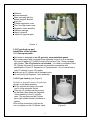
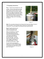
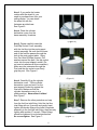
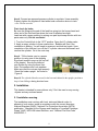
Owner’s manual
OUTDOOR PATIO HEATER
APH-4000PV
APH-4000SV
IMPORTANT
Your safety is very important, please read this manual thoroughly before you
install, operate and maintain this heater. Retain this manual for future reference.
If you have questions about assembly, operation, servicing or repair of this
heater, please contact your selling dealer or call us directly, we will gladly provide
assistance as required.
Warning: For Outdoor Use Only!
Table of Contents
Important Warning……………………………………………………… …………2
Introduction………………………………………………………………………….3
Specification………………………………………………………………………...3
Important Safety Precautions…………………………………………….…… .3-5
Assembly…………………………………………………………………………....5
Tools required………………………………………………………………………5
Unpacking…………………………………………………………..………………5
Component List………………………………………………..…………………...6
LP gas hook up and installation of the cylinder…………………………………6
Assembly Instructions………………………………………..…………………. 7-9
Installation………………………………………..…………………………….…...9
Operation……………………………………..………………………...……….…10
Preparation before lighting………………………….……………………….…...10
Leak Checking……………………………………….……………………………10
Lighting…………………………………………..………….. .………………..10-11
Setting Control………………………………………...………………………….. 11
Turn Off and Re-light……………………....………………………………….…. 11
Turn Off and Shut Down………………………..………………………….……. 11
Storage…………………………………………..……………………….….…11-12
Maintenance………………………………………………...……………………. 12
Troubleshooting………………………………………….………………….….…13
Service and Warranty Information………………………………………….…...14
Warranty Terms……………………………………………………...……………14
..
..
..
….
…
IMPORTANT WARNING
♦ Warning: For your safety
Fuels used in gas or oil-fired appliances and the products of combustion of such
fuels, contain chemicals known to the State of California to cause cancer, birth
defects and other reproductive harm. California Health & Safety Code Sec.25249.6
♦ Warning: For your safety
Improper installation, adjustment, alteration, service or maintenance can cause
injury or property damage from hazards of fire, explosion, burn, asphyxiation,
carbon monoxide poisoning. Please be sure you understand all operating the
instructions before operate or service this heater. Read this installation,
operation and maintenance instructions thoroughly before installing or servicing
this equipment.
♦ Warning: For your safety
Follow the correct lighting and usage procedures. Handle metal parts with care
to avoid injuries. Never allow children to operate this heater.
♦ Warning: For your safety
Do not store or use gasoline or other flammable vapors and liquids, solid combustibles
in the vicinity of this appliance. Keep a safe distance away from the heater as
2
recommended by the instructions.
♦ Warning: For your safety
If you smell gas:
1.Shut off gas to the appliance.
2.Extinguish any open flame near the appliance.
3.If odor continues, immediately call your gas supplier or local fire department.
Introduction
Thank you for choosing Outdoor Patio Heater. Please
take the time to read these instructions and follow each step carefully for safe
operation. Retain this manual for future reference. If you have any question
regarding this instruction, please stop and feel free to contact your selling dealer
or call our Customer Service Dept. directly for assistance.
Specification
Model No
Type of Gas
Input rating
Pressure
Gas Supply Inlet Pressure to
Regulator
Gas Cylinder
Overall Height
Reflector Diameter
Ignition System
Electrical connections
Net Weight
LPG (Propane) only
40,000 BTU/HR
11” W.C.
Max.150 PSI, Min. 5 PSI
A Standard 20 IB. propane gas cylinder
with a Type 1 QCC adapter only (not
included) .
90 Inches
34 Inches
Piezo Igniter
No required
64 IBS. (not including the cylinder)
Important Safety Precautions
To ensure safe use of your outdoor patio heater, you are requested to pay
close attention to these essential safety requirements.
This is a propane, direct-fired heater. It Means that all of the combustion
products enter the heated space. Even though this heater operates very
close to 100 percent combustion efficiency, but it still produces small
amounts of carbon monoxide. Carbon monoxide (called CO) is toxic. CO
can build up in a heated space and failure to provide adequate ventilation
could result in death. So, Always be sure there is plenty of fresh air when
the heater is in use. Always follow advice about ventilation in these
3
operating instructions. If any time gas odor is detected, shot off the
appliance immediately, find and correct the leak. Please set up the propane
supply with utmost care.
Alert both children and elders to the hazard of high surface emperatures.
Care must be taken for the supervision of children in the vicinity of an
operating or hot heater.
Your children and pets should be supervised when they are in area of
heater.
This outdoor patio heater must be used for outdoors only in a well
ventilated area and not be used in a vehicle or any enclosed building.
Always place the heater on a level stable surface.
Do not move, touch the heater while hot or burning.
Do not alter or modify the heater in any manner
Use only a U.S. Department of Transportation approved 20 pound
standard cylinder equipped with an TYPE 1 connection with QCC
(Quick Connect Coupler).
Use only with propane / LP Gas. Do not attempt to use any other fuel.
Always keep at least a 24 ‘’ clearance from any combustible material.
Do not use if the wind velocity is greater than 10 miles/hr.
Do not use if the environment temperature is below 40 F.
Do not spray aerosols near the heater while in use.
Do not clean heater with combustible or corrosive cleaners. Use warm, soapy
water.
Do not hang clothing or flammable materials either on or near heater
Do not move, touch the heater while it is hot or in operation.
Place the control knob on OFF position when heater is not in use and always
disconnect the gas cylinder at its main valve and store it outdoors where it is
not accessible to children. Never store a propane cylinder indoors
Always 45 minutes to cool down after use before attempting to move your
heater.
Use only the hose and regulator with the heater provided by the factory. Check
the regulator and hose assembly before each use. If you find an excessive
abrasion or hose is cut, please replace with the Regulator assembly listed on
the parts list right away.
Never use the heater if the ballast weight is not assembled into the base. The
base must be weighted to prevent possible tipping.
Inspect heater before each use and inspect annually by a qualified service
person. Do not operate a damaged heater.
Leak check only with soapy water when the initial assembly and after every
cylinder is replaced. All gas connections should be checked. Look for bubbles.
Never use flame!
Warning:
When the heater is to be operated in the presence of other people, the user is
4
instructions, and of the hazards involved. If this heater is used in a commercial or
rental installation, it is the responsibility of the purchaser to check with the local
codes for properly acquainting with the safety precautions and instructions.
Failure to comply with the precautions and instructions provided with this
heater can result in death, serious bodily injury and property loss or
damage from hazards of fire, explosion, burn, asphyxiation, carbon
monoxide poisoning. Be sure you understand all operation instructions
before attempting to operate or service this heater.
1. Assembly
Note: The assembly of this heater requires basic mechanical skills. Proper
assembly is the responsibility of the installer. All service and repair should
be done by a qualified person.
1.1 Tools required
8mm, 10mm, 11mm, 12mm Socket
#2 & #3 Phillips Head Screwdriver
Pliers or Channel Lock Pliers
Crescent or Open End Wrenches
Caution:
Do not use Teflon Tape or any thread sealing compounds where connections
between heater head to Fuel-Tube and Regulator / Hose assembly to FuelTube.
1.2 Unpacking
Remove the Fuel-tube, the Post and Heater burner assembly from the
Box 2 of 2.
Take out the heater burner assembly from the base assembly by removing the
three Hex-Nuts, Flat washers and Lock washers, then screw the nuts and
washers back onto the bolts at the top of the burner assembly.
Remove all shipping packaging foam on the components.
Check the fasteners, Regulator assembly and the Owner’s Manual provided
by the factory.
Remove the Reflector from the Box 1 of 2.
Check the heater for any shipping damage, if any is found, immediately
contact and return this heater to the dealer or distributor where purchased.
Retain all packaging material and carton until heater warranty has expired.
Any warranty returns require original packing and carton.
1.3 Component List (see Figure 1)
5
Reflector
Burner assembly
Base assembly with the
allast weight & Bracket
uel -line
Cylinder decorative cover
Post / the Slip socket cover
Regulator / hose assembly
Fastener package
Owner’s manual
Wheel Kit (optional part)
( Figure 1)
1.4 LP gas hook up and
installation of the cylinder
1.4.1 Gas requirements:
Our heater is designed to use LP gas only, never substitute gases.
he heater comes with a regulator/hose assembly for hook up to a standard
20 pound (5 gallon) LP Overfill Protection Device and Type 1 fitting equipped
gas cylinder. The LP cylinder is not included. You need to purchase a filled
LP Cylinder that must be constructed and marked in accordance with
specifications of the U.S. Department of Transportation. Do not use dented or
rusty LP cylinder by your LP supplier.
Never use an LP cylinder with a damaged valve.
Do not modify the Regulator / hose assembly.
1.4.2 LP gas hook up (see Figure 2)
The heater is designed to house a 20 pound gas
cylinder on the base assembly.
Lift the cylinder decorative cover and
rest it on the triangular Socket.
Place the LP cylinder into the housing
on the Base, then attach the Regulator
/ hose assembly to the LP cylinder
valve. The regulator and the Cylinder
have right-handed threads (clockwise to
tighten).
Be sure this connection is tight but do
not over tighten on the LP cylinder valve.
6
(Figure 2)
1.5 Assembly Instructions
Step 1. Set the burner assembly on a flat
surface. Remove the protective end cap
from the only one end of the male flared
fitting at the end of the fuel line. Leave
the other end cap on to protect the fitting
while you are doing this assembly. Screw
the male flared fitting into the inlet fitting
at the base of the burner head and tighten
using a ¾ wrench. Be sure that the
connection is tight (do not over-tighten).
See Figure 3
(Figure 3)
Note: The connection between the fuel line and the burner inlet fitting is brass-to
brass connection. This connection doesn’t require any thread sealing
compounds. The flare design of the threads provides a gas tight seal.
Step 2. Carefully slide the post
(Note: the Slip socket cover
has been assembled to the
post) over the fuel line. The post
fit one way only because the
holes drilled different positions.
The end of the post that connects
to the burner head has four
holes drilled about ½” below
the top of the post. That other
end of the post that will connect
to the support socket has four
holes drilled about 11/2” from
the other end of the post. Attach
the post to the burner assembly
using four Pan Head (Phillips) screws,
Flat washers and Lock washers. Make
sure that the setscrews firmly grip the
post. See Figure 4.
(Figure 4)
7
Step 3. If you prefer the heater
comes with the wheel kit, you
need to purchase them from your
selling dealer. You can attach
the wheel kit with the
fasteners provided now.
See Figure 5.
Step 4. Place the cylinder
decorative cover over the
base assembly / brackets.
(
(
(Figure 5)
Step 5. Please carefully insert the
Post/Slip Socket Cover assembly
with the fuel line into the post support
socket assembly. Be sure that the lower
end of the fuel line passes through the
hole in the post support plate. Using
four Pan Head (Phillips) screws, Flat
washers secure the post / the slip socket
cover into the post support socket. (Do
not use lock washers at this connection).
Make sure the setscrews through the
Post and the slip socket cover firmly
grip the post. See Figure 6
(
(Figure 6)
Step 6. Carefully lift up the cylinder
decorative cover. Tilt the cylinder
decorative cover and rest it on the
post support Socket by against the
Hex-bolts. Make sure that the
cylinder decorative cover is in a
stable position. Never allow it slides!
See Figure 7
Step 7. Remove the other protective end cap
from the fuel line inlet fitting. Hold the fuel line
inlet fitting with an ¾ wrench and gently handtighten the female fitting at the hose & regulator
assembly to the fuel line inlet fitting, then securely
tighten with another ¾” wrench. These fittings
should be tightened in a clockwise direction.
Do no over-tighten. See Figure 7.
8
(Figure 7)
Step 8. Connect an approved propane cylinder to regulator / hose assembly.
Properly tighten the regulator’s hand wheel and connection device to tank
valve. Do not use tools.
First check for leaks:
Be sure the fittings at the end of the feed line going into the burner head and
other end of the fuel feed line where the hose is attached are tight.
Leak test with a soapy solution by mixing one part liquid soap solution with two
parts water only. Do not use flame!
1. Turn the Control Knob to the “OFF” position. Open the LP cylinder valve.
2. Apply a soapy solution to these connections. Bubbles will form if the
connection is leaking. You will need to reconnect and leak test again. Upon
completion of the leak test, turn off the LP cylinder valve and disconnect and
remove the cylinder. Go to the next step.
Step 9. Tilt the heater over to a proper
position (or using one of the shipping
Styrofoam inserts to prop up the top half
of the heater). Secure the reflector
onto Emitter by using the three HexNuts, Flat washers and Lock washers.
Make sure that the nuts are tight properly.
Stand the heater upright. As shown in
Figure 8.
(Figure 8)
Step 10. The cylinder Must be secured in the base and chained in the upright position to
keep it from falling or being knocked over.
2. Installation
This heater is intended for use outdoors only! Don’t be used on any moving
objects and any enclosed areas!
2.1 Installation warning
The installation must conform with local, state and federal codes. In
absents of such codes, install in accordance with the current American
National Standard (ANSI) / National Fire Protection Association (NFPA)
publication “ Standard for the Storage and Handling of Liquefied Petroleum
Gases” ANSI / NFPA 58-Latest Revision, and “ National Fuel Gas Code”
ANSOZ223.1.
9
2.2 Minimum clearances
Minimum 24” clearances from combustible materials must be maintained at
all times while the heater is in operation.
3. Operation
3.1 Preparation before lighting
3.1.1 Check any possible shipping damage of the heater. If any is found,
immediately contact your selling dealer or call us directly.
3.1.2 Please review thoroughly and be sure you understand all of the “safety
precautions and warnings”.
3.1.3 Make sure control knob is at “OFF” position.
3.1.4 Place the LP cylinder onto the Cylinder Base. Connect the Regulator /
hose assembly to the cylinder by rotating the Regulator’s hand wheel
clockwise into the cylinder’s valve and securely tighten.
3.1.5 If attempting to relight a hot heater, always wait until the heater is cool.
3.2 Leak Checking
Check all of gas connections in the heater with soapy water.
Apply soap solution to all propane connections, especially the fuel connections
between the Regulator connection device to the Cylinder valve, the fitting at
the end of the Fuel Line to the Burner Head and the other end of the Fuel Line
to the Hose assembly.
Inspect all propane connections, look for bubbles.
If bubbles appear, there is a leak. Disconnect and reconnect, try again.
If no bubbles appear, the connection is safe, continue the next step: Lighting.
If the leak persists, turn cylinder valve OFF and contact your selling dealer or
call our Customer Service Dept. directly for assistance and advice.
Warning:
Perform Leak test outdoors only.
Never leak test when smoking.
Do not use a flame to check for leaks.
3.3 Lighting
3.3.1 To light the pilot
Lift the cylinder cover from the base and set it the stable position. Turn the
cylinder valve on.
The first step is to purge the fuel line when a new or refilled propane cylinder is
installed.
Gently depress the control knob at the faceplate panel and rotate it to “PILOT”
10
position. Depress and hold the control knob for 2-3 minutes to purge the air
from the gas line and flow of gas to the pilot assembly. Do not press on the
igniter while you are purging the line.
3.3.2 Important Light step
While Hold the control knob in, press the Piezo Igniter button (red button), the
Piezo Igniter will be lit. On occasion conduct to light several times.
After the pilot is lit, continue to depress the control knob for 30 seconds to heat
the thermocouple. Release the control knob and the pilot should stay lit. You
can visually observe the ignition of the pilot through sliding the hole cover at
the base of the heater head assembly.
Caution:
Close the hole cover once the pilot flame stays on. Do not attempt to slide this
cover when the main burner is lighting, operating.
Lower the cylinder cover onto the base.
3. 4 Setting Control
Press and turn the control knob from “ PILOT” to full “ON” position, the burner
will light immediately for maximum heat output. The knob can be turned back
to reduce or desired setting.
Note: While in use, the burner flame should be mainly blue in appearance with a
small amount of yellow.
Caution: White smoke may appear around the emitter screen during the first few
minutes of the initial burning. The burner is burning off oily materials
during the first few minutes of the initial burning.
3.5 Turn Off and re-light
If you turn the knob back to “PILOT” position, the main burner will extinguish
but the pilot will remain lit.
Turn the control knob clockwise to “OFF” position.
Note: Do not attempt to relight the heater for 5 minutes after turn off the
heater. The safety system built into the heater will not allow you to
immediately re-light the heater from the “OFF” position.
Repeat following “Important Light step” procedure, you don’t have to wait more
than few seconds to restart the “PILOT” light and then ignite the main burner.
3.6 Turn Off and Shut Down
Turn the control knob clockwise to “OFF” position.
Turn off gas supply.
Disconnect the cylinder and remove when the heater is not in use.
4. Storage
11
Allow at least 45 minutes for the heater to cool down after using.
Store the heater upright in a sheltered area away from inclement weather such
as rain, snow and dust.
We have our patio heater cover available to protect the burner head. We
recommend using our heat head cover when your heater is in storage.
Note: Be sure the heater is cool down before using the cover.
If the heater is not to be used for an extended period of time, disconnect and
remove the Propane Gas Cylinder and store in accordance with the "Standard
for Storage and Handling of Liquefied Petroleum Gases", ANSI/INFPA 58latest edition.
Beware of Spiders and Insects
Spiders and small insects
occasionally spin
webs or make nests in the burner tubes and or orifices during
warehousing and transit. These webs or nests can lead to a gas flow
obstruction, which could result in a fire in and around the burner tube.
This type of fire is know as FLASHBACK and can cause serious damage to
your heater and creates an unsafe operating condition for the user.
Although an obstructed burner tube is not the only cause of flashback, it’s
the most common cause.
Check control compartment burners and circulation air passageways for
free air passage. Make sure that there are no obstructions
5. Maintenance
To obtain the best performance from your heater make sure you perform the
following maintenance activities on a regular basis:
Keep exterior surfaces clean. Use warm soapy water for cleaning.
Never use flammable or corrosive cleaning agents. Be sure to keep the
area around the burner and control assembly dry at all times.
Airflow must be unobstructed. Clear insect nests or webs away from
your heater’s exterior and interior using a straight piece of wire and wire
brush or vacuum cleaner at least once a year or immediately upon
indication of any of the following systems:
a. Flashback
b. Smell the fuel gas
c. Predominate yellow flames
d. Excessive popping noises during operation
e. Uneven emitter glow
Carbon deposits may create a fire hazard. Clean dome and emitter with
warm soapy Water if necessary.
Caution:
12
Never use wood or plastic, it may break and block the parts.
Never spray any cleaning product on the emitter grid or burner area.
6. Troubleshooting
Problem
Burner won’t light
Possible Cause
Air in gas line
Purge gas line by holding
control knob at “PILOT”
position for at least two
minutes.
Blockage in orifice
Clean orifice
Gas pressure is low
Replace cylinder
Igniter is not sparking
Use match to light pilot
through the hole at the base of
heater head.
Thermocouple
properly
is
not
operating
Dirt build up around pilot orifice
Pilot won’t stay lit
What to do
There may be a leak in the system
that has been detected by the
safety system in the regulator.
High wind condition blowing out
pilot flame
Replace thermocouple
Clean pilot orifice
Check connections at hose to
fuel line and fuel line to heater
head.
Be sure Regulator
hand wheel is tightened to
cylinder valve properly.
Put heater in more protected
location.
Do not use heater in winds:
greater than 10 miles/hr. or
temperature: below 40 F.
Heater not leveled
Level the heater
The burner tilted
Straighten burner
Gas pressure is low
Replace cylinder
Outdoor temperature is below 40
degrees Fahrenheit and cylinder is
less than 20% full
Refill the cylinder. Using full
one.
Stop using this heater when
the temperature is below 40 F.
Emitter glows uneven
The burner burn off oily materials
During the first few minutes of
the initial burning
Blockage in burner
Remove blockage and clean
burner inside & outside
The base is not on a level surface
Place heater
surface
Dirt or film on dome and emitter
Clean dome and emitter
Blockage in burner
Remove blockage and clean
burner and clean burner inside
& outside.
Burner emits smoke
Carbon build up
13
on
a
level
7. Service and warranty Information
To learn how to service and procure parts for worn out, defective or
damaged components, please contact your selling dealer or call us
directly for assistance. Please provide us with heater’s model number
and the serial number.
Warning: Use our original equipment replaced parts only. Use
unauthorized parts or modification of parts can void warranty and create an
unsafe condition.
8. Warranty Terms
Subject to the conditions set out below, this product is warranted to
the original purchaser to be free from defects in workmanship and
materials for 12 months from the date of purchase.
8.1 Satisfactory proof of the purchase date must be furnished at
the time of notification of the defect for any claim under the
warranty to be enforceable.
8.2 This warranty covers all parts found defective in workmanship
and / or materials during the warranty period and can be
repaired or replaced at the discretion of the manufacture at no
cost to the original purchaser.
8.3
This warranty will be void and accordingly no claim of any
nature will be enforceable if the product has not been
assembled, installed or operated according to the instructions,
subjected to abuse, improperly treated, neglected, rusted by
exposure to the element, misused and / or if any repairs,
maintenance, or service has been done by an unauthorized
person.
8.4
Return must be properly packaged and freight prepaid to the
dealer from whom the product was acquired.
8.5
Each of the manufacturer, distributor and retailer will not be
liable for any incidental or consequential loss or damage
arising from the installation or operation for the product and / or
the failure of any part for any reason.
8.6 There are no other express or implied warranties, except for
those stipulated herein. This warranty gives specific rights and
14
the original purchaser may have additional rights and remedies
in law.
8.7 This warranty does not cover commercial or rental use.
15

![[ 富士ドライケム4000sV ] ≫PDF](http://vs1.manualzilla.com/store/data/006617052_2-e4de64e6c8ab25b2a0dccdfd62fbe55f-150x150.png)