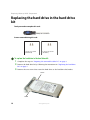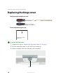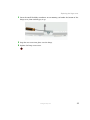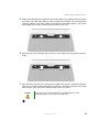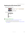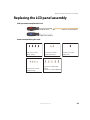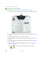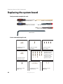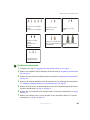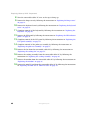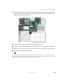
1
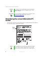
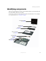
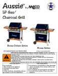
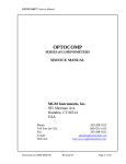
Service Guide
Gateway M275
Contents
Replacing Gateway M275 Components . . . . . . . . . . . . . . . . . . . . . . . . . . . . . . . . . . . . 1
Identifying the convertible tablet PC model . . . . . . . . . . . . . . . . . . . . . . . . . . . . . . . . . . . . . . 2
Identifying components . . . . . . . . . . . . . . . . . . . . . . . . . . . . . . . . . . . . . . . . . . . . . . . . . . . . . 3
Preparing your work space . . . . . . . . . . . . . . . . . . . . . . . . . . . . . . . . . . . . . . . . . . . . . . . . . . 4
Preventing static electricity discharge . . . . . . . . . . . . . . . . . . . . . . . . . . . . . . . . . . . . . . . . . . 5
Preparing the convertible tablet PC . . . . . . . . . . . . . . . . . . . . . . . . . . . . . . . . . . . . . . . . . . . . 6
Disconnecting from the port replicator . . . . . . . . . . . . . . . . . . . . . . . . . . . . . . . . . . . . . . 6
Removing the battery . . . . . . . . . . . . . . . . . . . . . . . . . . . . . . . . . . . . . . . . . . . . . . . . . . . 7
Replacing the pen point . . . . . . . . . . . . . . . . . . . . . . . . . . . . . . . . . . . . . . . . . . . . . . . . . . . . . 8
Replacing the hard drive kit . . . . . . . . . . . . . . . . . . . . . . . . . . . . . . . . . . . . . . . . . . . . . . . . . . 9
Replacing the hard drive in the hard drive kit . . . . . . . . . . . . . . . . . . . . . . . . . . . . . . . . . . . 12
Replacing the optical drive . . . . . . . . . . . . . . . . . . . . . . . . . . . . . . . . . . . . . . . . . . . . . . . . . 14
Replacing the hinge cover . . . . . . . . . . . . . . . . . . . . . . . . . . . . . . . . . . . . . . . . . . . . . . . . . . 16
Replacing the keyboard cover . . . . . . . . . . . . . . . . . . . . . . . . . . . . . . . . . . . . . . . . . . . . . . . 18
Replacing the keyboard . . . . . . . . . . . . . . . . . . . . . . . . . . . . . . . . . . . . . . . . . . . . . . . . . . . . 20
Adding or replacing memory modules . . . . . . . . . . . . . . . . . . . . . . . . . . . . . . . . . . . . . . . . . 25
Adding or replacing memory in the memory bay . . . . . . . . . . . . . . . . . . . . . . . . . . . . . 25
Replacing memory under the keyboard . . . . . . . . . . . . . . . . . . . . . . . . . . . . . . . . . . . . 28
Replacing the LED indicator panel . . . . . . . . . . . . . . . . . . . . . . . . . . . . . . . . . . . . . . . . . . . 31
Replacing the LCD panel assembly . . . . . . . . . . . . . . . . . . . . . . . . . . . . . . . . . . . . . . . . . . 33
Replacing the LCD panel . . . . . . . . . . . . . . . . . . . . . . . . . . . . . . . . . . . . . . . . . . . . . . . . . . . 38
Repairing the digital panel . . . . . . . . . . . . . . . . . . . . . . . . . . . . . . . . . . . . . . . . . . . . . . . . . . 46
Replacing the palm rest assembly . . . . . . . . . . . . . . . . . . . . . . . . . . . . . . . . . . . . . . . . . . . 51
Replacing the cooling fan . . . . . . . . . . . . . . . . . . . . . . . . . . . . . . . . . . . . . . . . . . . . . . . . . . 56
Replacing the cooling assembly . . . . . . . . . . . . . . . . . . . . . . . . . . . . . . . . . . . . . . . . . . . . . 60
Replacing the CMOS battery . . . . . . . . . . . . . . . . . . . . . . . . . . . . . . . . . . . . . . . . . . . . . . . . 63
Replacing the modem . . . . . . . . . . . . . . . . . . . . . . . . . . . . . . . . . . . . . . . . . . . . . . . . . . . . . 66
Replacing the IEEE 802.11 Mini PCI card . . . . . . . . . . . . . . . . . . . . . . . . . . . . . . . . . . . . . 70
Replacing the latch . . . . . . . . . . . . . . . . . . . . . . . . . . . . . . . . . . . . . . . . . . . . . . . . . . . . . . . 76
Replacing the speaker . . . . . . . . . . . . . . . . . . . . . . . . . . . . . . . . . . . . . . . . . . . . . . . . . . . . . 81
Replacing the system board . . . . . . . . . . . . . . . . . . . . . . . . . . . . . . . . . . . . . . . . . . . . . . . . 84
www.gateway.com
i
ii
www.gateway.com
Replacing Gateway M275
Components
Important
This service guide is not intended to
be provided to individual users or
consumers. It cannot be provided to
anyone other than an authorized
service provider.
Use this service guide to help plan maintenance tasks
for the Gateway M275 convertible tablet PC. All
tasks covered in this guide can be performed by an
authorized field technician without jeopardizing
the tablet PC’s warranty.
1
Replacing Gateway M275 Components
Important
For information on the convertible tablet PC’s general maintenance,
technical support, safety notices, and regulatory notices, see the
Gateway user guide.
Tips & Tricks
If you have suggestions regarding the content of this guide, send an
e-mail with the subject “Service Guide Comments” to
[email protected].
Identifying the convertible tablet PC
model
The label on the bottom of the convertible tablet PC contains information that identifies
the convertible tablet PC model and its features.
Gateway
model
number
Caution
2
It is important that you use the correct service guide for the convertible
tablet PC. Failure to follow the approved tasks for the convertible
tablet PC model may result in damage to the convertible tablet PC.
www.gateway.com
Identifying components
Identifying components
Where screw measurements are shown, the first number indicates screw head width, and
the second number indicates screw length.
Use this chart to identify the main components of the convertible tablet PC. For a complete
list of replaceable parts, see “Contents” on page i.
LCD panel assembly
(see page 33)
Keyboard cover
(see page 18)
Keyboard
(see page 20)
Palm rest assembly
(see page 51)
Cooling assembly
(see page 60)
Modem
(see page 66)
System board
(see page 84)
www.gateway.com
3
Replacing Gateway M275 Components
Preparing your work space
Before performing maintenance on the convertible tablet PC, make sure that your work
space and the convertible tablet PC are correctly prepared.
4
■
Wear a grounding (ESD) wrist strap, and use a grounded or dissipative work mat.
■
Use a stable and strong table, and make sure that the table top is large enough to
hold each component as you remove it.
■
Use bright lighting to make part identification easier.
■
Keep your work surface free from clutter and dust that may damage components.
■
Use a magnetized screwdriver for removing screws.
■
When removing components that are attached to the convertible tablet PC by a cable,
unplug the cable before removing the screws, when possible, to avoid damaging the
cable.
■
As you remove components and screws, lay them toward the rear of your work surface
(behind the convertible tablet PC) or far enough to the side that your arms do not
accidentally brush them onto the floor.
■
To help keep track of screws, try the following:
■
Place each component’s screws in their own section of a parts sorter.
■
Place each component’s screws next to the component on your work surface.
■
Print the first page of each task, then place the page toward the rear of your work
surface. As you remove screws, place the screws in their respective boxes on the
page. Where screw measurements are shown, the first number indicates screw head
width, and the second number indicates screw length.
■
After loosening screws that are deeply recessed in a hole (for example, on the
bottom of the base assembly), you can leave the screws in the holes if you place
small pieces of masking tape over the hole openings. When reassembling the
component, just remove the tape and tighten the screws.
■
When you place flat-headed screws on your work surface, stand them on their
heads to prevent the screws from rolling off the table.
www.gateway.com
Preventing static electricity discharge
Preventing static electricity discharge
Important
Before performing maintenance on the convertible tablet PC, you
should read and understand the information in this section.
The components inside your convertible tablet PC are extremely sensitive to static
electricity, also known as electrostatic discharge (ESD).
Warning
To avoid exposure to dangerous electrical voltages and moving parts,
turn off your convertible tablet PC and unplug the power cord, modem
cable, and network cable before opening the case.
Warning
To prevent risk of electric shock, do not insert any object into the vent
holes of the convertible tablet PC.
Before performing maintenance on the convertible tablet PC, follow these guidelines:
■
Avoid static-causing surfaces such as carpeted floors, plastic, and packing foam.
■
Remove components from their antistatic bags only when you are ready to use them.
Do not lay components on the outside of antistatic bags because only the inside of
the bags provide electrostatic protection.
■
Always hold components by their edges. Avoid touching the edge connectors. Never
slide components over any surface.
■
Wear a grounding wrist strap (available at most electronics stores) and attach it to a
bare metal part of your workbench or other grounded connection.
■
Touch a bare metal surface on your workbench or other grounded object.
www.gateway.com
5
Replacing Gateway M275 Components
Preparing the convertible tablet PC
Warning
To avoid exposure to dangerous electrical voltages and moving parts,
turn off the convertible tablet PC, remove the battery, and unplug the
power cord, modem cable, and network cable before opening the
case. Replace the cover before you restore power or reconnect the
modem and network cables.
To prepare the convertible tablet PC for maintenance:
1
2
3
Make sure that the CD or DVD drive is empty.
4
Disconnect from the optional port replicator. For more information, see
“Disconnecting from the port replicator” on page 6.
5
Remove the battery. For more information, see “Removing the battery” on page 7.
Disconnect all peripheral devices and remove any PC Cards.
Turn off the convertible tablet PC and unplug the power cord, modem cable, and
network cable.
Disconnecting from the port replicator
To separate your convertible tablet PC from the port replicator:
6
1
Pull up on the docking release latch. Your convertible tablet PC will move out and
away from the port replicator.
2
Lift your convertible tablet PC off of the port replicator.
www.gateway.com
Preparing the convertible tablet PC
Removing the battery
To remove the battery:
1
2
Turn the convertible tablet PC over so the bottom is facing up.
Slide the battery lock to the unlocked position.
Battery latch
Battery
Battery lock
3
Slide the battery release latch and lift the battery out of the bay.
www.gateway.com
7
Replacing Gateway M275 Components
Replacing the pen point
Normal use wears down the pen’s point, so the pen ships with extra points and a
replacement tool.
To replace the pen point:
8
1
Use the replacement tool to grab the old point and pull it out of the pen.
2
Insert a new point and apply slight pressure to set it in place.
www.gateway.com
Replacing the hard drive kit
Replacing the hard drive kit
Tools you need to complete this task:
Phillips #0 screwdriver
Screws removed during this task:
2 chrome 2.5 × 6 mm
(hard drive kit)
Hard
drive
kit
www.gateway.com
9
Replacing Gateway M275 Components
To replace the hard drive kit:
1
2
Complete the steps in “Preparing the convertible tablet PC” on page 6.
Remove the two screws securing the hard drive kit to the convertible tablet PC.
Screws
Tips & Tricks
3
10
Use a magnetic screwdriver or turn the convertible table PC over to
remove the screws.
Slide the hard drive kit out of the convertible tablet PC.
www.gateway.com
Replacing the hard drive kit
Important
4
5
If your new hard drive does not include the hard drive kit bracket,
complete the steps in “Replacing the hard drive in the hard drive kit”
on page 12 before proceeding.
Slide the new hard drive kit into the convertible tablet PC.
Replace the screws that secure the hard drive kit to the convertible tablet PC.
www.gateway.com
11
Replacing Gateway M275 Components
Replacing the hard drive in the hard drive
kit
Tools you need to complete this task:
Phillips #0 screwdriver
Screws removed during this task:
2 chrome 2.5 × 6 mm
(hard drive kit)
2 chrome 2.5 × 6 mm
(hard drive)
To replace the hard drive in the hard drive kit:
1
2
Complete the steps in “Preparing the convertible tablet PC” on page 6.
3
Remove the two screws that secure the hard drive to the hard drive kit bracket.
Remove the hard drive kit by following the instructions in “Replacing the hard drive
kit” on page 9.
Screw
Screw
12
www.gateway.com
Replacing the hard drive in the hard drive kit
4
5
6
7
8
Remove the bracket from the old drive.
Insert the new drive into the bracket so the screw holes line up.
Replace the two screws that secure the bracket to the drive.
Slide the hard drive kit into the convertible tablet PC.
Replace the screws that secure the hard drive kit to the convertible tablet PC.
www.gateway.com
13
Replacing Gateway M275 Components
Replacing the optical drive
Important
Install only a Gateway M275 optical drive in the optical drive bay.
Tools you need to complete this task:
Phillips #0 screwdriver
Screws removed during this task:
1 chrome 2.5 × 6 mm
(optical drive)
To replace the optical drive:
1
14
Complete the steps in “Preparing the convertible tablet PC” on page 6.
www.gateway.com
Replacing the optical drive
2
Remove the optical drive latch screw, then slide the optical drive release latch next
to the optical drive screw.
Screw
3
Slide the old drive out of the convertible tablet PC.
4
Slide the new drive into the convertible tablet PC. Installing the optical drive
repositions the optical drive release latch.
5
Replace the optical drive latch screw.
www.gateway.com
15
Replacing Gateway M275 Components
Replacing the hinge cover
Tools you need to complete this task:
Flat-blade driver
- OR -
Scribe or non-marring tool
Phillips #0 screwdriver
Screws removed during this task:
1 chrome 2.5 × 5 mm
(hinge cover)
To replace the hinge cover:
1
2
3
Complete the steps in “Preparing the convertible tablet PC” on page 6.
Turn the convertible tablet PC over so the top is facing up.
Remove the hinge cover screw from the back of the hinge.
Screw
16
www.gateway.com
Replacing the hinge cover
4
Insert the small flat-blade screwdriver or non-marring tool under the bottom of the
hinge cover, then carefully pry it up.
5
6
Snap the new cover into place over the hinge.
Replace the hinge cover screw.
www.gateway.com
17
Replacing Gateway M275 Components
Replacing the keyboard cover
Tools you need to complete this task:
Flat-blade driver
- OR -
Scribe or non-marring tool
To replace the keyboard cover:
1
2
3
4
Complete the steps in “Preparing the convertible tablet PC” on page 6.
Turn the convertible tablet PC over so the top is facing up.
Open the LCD panel to the normal viewing position.
Insert the small flat-blade screwdriver under the bottom of the keyboard cover
between the F11 and F12 keys and gently pry it up.
Tips & Tricks
18
Inserting a piece of cloth between the screwdriver and keyboard will
help prevent damage to the convertible tablet PC.
www.gateway.com
Replacing the keyboard cover
5
Remove the keyboard cover from the convertible tablet PC by pulling the cover toward
you and at the same time lifting its front to clear the keyboard. You will hear small
snapping sounds as the cover comes away from the convertible tablet PC. Be careful
not to break off the tabs located on the bottom of the cover.
6
Slide the tabs on the bottom side of the new cover under the convertible tablet PC
frame.
7
Press down on the cover in several places to make sure that it is correctly mounted.
The cover is correctly mounted when you can run your finger along the cover and
find no loose spots. The cover should be flat all the way across.
Caution
If the cover is not correctly replaced, the convertible tablet PC could
be damaged when you try to close the LCD panel.
www.gateway.com
19
Replacing Gateway M275 Components
Replacing the keyboard
Tools you need to complete this task:
Flat-blade driver
- OR -
Scribe or non-marring tool
Phillips #0 screwdriver
Screws removed during this task:
2 chrome 2.5 × 6 mm
(keyboard - bottom)
4 chrome 2.5 × 2.5 mm
(keyboard - top)
To replace the keyboard:
1
20
Complete the steps in “Preparing the convertible tablet PC” on page 6.
www.gateway.com
Replacing the keyboard
2
Remove the two keyboard screws marked with a K.
Screw
Screw
3
4
Turn the convertible tablet PC over so the top is facing up.
5
Remove the four keyboard screws that secure the keyboard to the convertible
tablet PC.
Remove the keyboard cover by following the instructions in “Replacing the keyboard
cover” on page 18.
Screws
www.gateway.com
21
Replacing Gateway M275 Components
22
6
Lift the back edge of the keyboard slightly, then carefully slide the keyboard back until
the four tabs on the front edge of the keyboard are free from their slots. Be careful
not to damage the LCD panel.
7
Slowly rotate the keyboard toward you so it lies keys-down on top of the convertible
tablet PC. Be careful not to damage the LCD panel.
8
Carefully insert the small flat-blade screwdriver between the keyboard cable and the
black plastic hinge where the cable connects to the system board. Gently lift the hinge
off the cable. The cable is now free and you can remove the keyboard.
9
Place the new keyboard keys-down on the convertible tablet PC with the space bar
away from you.
10
Make sure that the black plastic hinge on the system board keyboard connector is in
the raised position.
11
Insert the end of the keyboard cable between the black plastic hinge and the white
connector.
www.gateway.com
Replacing the keyboard
Important
12
13
14
The plug is correctly oriented if the cable is not twisted.
Press the black plastic hinge onto the keyboard cable.
Rotate the keyboard toward the LCD panel until the keyboard is almost face-up.
Insert the four tabs on the front edge of the keyboard into the corresponding slots
under the palm rest.
Tabs
15
Gently press the keyboard down until it is flat all the way across. The keyboard should
easily fall into place. Be careful not to damage the LCD panel.
www.gateway.com
23
Replacing Gateway M275 Components
16
Replace the four keyboard screws.
Screws
24
17
Turn the convertible tablet PC over so the top is facing down, then replace the two
keyboard screws.
18
Reassemble the convertible tablet PC.
www.gateway.com
Adding or replacing memory modules
Adding or replacing memory modules
The convertible tablet PC uses memory modules called SO-DIMMs (Small Outline Dual
Inline Memory Modules). The modules are available in various capacities and any module
can be placed in the memory bay. Use only memory modules designed for the
Gateway M275 for upgrading the memory.
SO-DIMMs are located in two places inside the convertible tablet PC. Both SO-DIMMs can
be upgraded. For instructions on upgrading the SO-DIMM located on the bottom of the
convertible tablet PC, see “Adding or replacing memory in the memory bay” on page 25.
For instructions on upgrading the SO-DIMM located under the keyboard of the convertible
tablet PC, see “Replacing memory under the keyboard” on page 28.
Important
Use only memory modules designed for the Gateway M275.
Adding or replacing memory in the memory bay
Tools you need to complete this task:
Flat-blade driver
- OR -
Scribe or non-marring tool
Phillips #0 screwdriver
www.gateway.com
25
Replacing Gateway M275 Components
To add or replace memory modules:
1
Complete the steps in “Preparing the convertible tablet PC” on page 6.
Memory
bay
2
Loosen the two captive screws that secure the memory cover. (These screws cannot
be removed.)
Screws
3
26
Lift the screw side of the cover upward, then slide the cover out.
www.gateway.com
Adding or replacing memory modules
4
If you are removing a module, gently press outward on the clip at each end of the
memory module until the module tilts upward.
5
Pull the memory module out of the slot.
6
Hold the new or replacement module at a 30-degree angle and press it into the empty
memory slot. This module is keyed so it can only be inserted in one direction. If the
module does not fit, make sure that the notch in the module lines up with the tab
in the memory bay.
Important
7
8
Use only memory modules designed for the Gateway M275.
Gently push the module down until it clicks in place.
Replace the memory bay cover and tighten the cover screws.
www.gateway.com
27
Replacing Gateway M275 Components
Replacing memory under the keyboard
Tools you need to complete this task:
Flat-blade driver
- OR -
Scribe or non-marring tool
Phillips #0 screwdriver
Screws removed during this task:
2 chrome 2.5 × 6 mm
(keyboard - bottom)
Important
4 chrome 2.5 × 2.5 mm
(keyboard - top)
Use only memory modules designed for the Gateway M275.
To replace memory modules:
1
2
Complete the steps in “Preparing the convertible tablet PC” on page 6.
3
4
Turn the convertible tablet PC over so the top is facing up.
5
Open the keyboard compartment by following the instructions in “Replacing the
keyboard” on page 20.
Remove the two keyboard screws marked with a K. For more information, see Step 2
on page 21.
Remove the keyboard cover by following the instructions in “Replacing the keyboard
cover” on page 18.
Tips & Tricks
28
You do not need to disconnect the keyboard from the system board.
www.gateway.com
Adding or replacing memory modules
6
Gently press outward on the clip at each end of the memory module until the module
tilts upward.
7
Pull the memory module out of the slot.
8
Hold the new or replacement module at a 30-degree angle and press it into the empty
memory slot. This module is keyed so it can only be inserted in one direction. If the
module does not fit, make sure that the notch in the module lines up with the tab
in the memory bay.
Important
Use only memory modules designed for the Gateway M275.
www.gateway.com
29
Replacing Gateway M275 Components
9
10
30
Gently push the module down until it clicks in place.
Reassemble the convertible tablet PC.
www.gateway.com
Replacing the LED indicator panel
Replacing the LED indicator panel
Tools you need to complete this task:
Flat-blade driver
- OR -
Scribe or non-marring tool
Phillips #0 screwdriver
Screws removed during this task:
2 black 2.5 × 2.5 mm
(LED panel)
To replace the LED indicator panel:
1
2
3
Complete the steps in “Preparing the convertible tablet PC” on page 6.
Turn the convertible tablet PC over so the top is facing up.
Remove the keyboard cover by following the instructions in “Replacing the keyboard
cover” on page 18.
www.gateway.com
31
Replacing Gateway M275 Components
4
Remove the two screws securing the LED indicator panel to the convertible tablet PC.
Screws
32
5
Insert the small flat-blade screwdriver or non-marring tool under the right side of the
indicator panel and gently pry it up about ¼ inch, then lift the entire panel from the
convertible tablet PC.
6
Align the new indicator panel’s screw holes with the holes on the convertible
tablet PC, then press the panel into place.
7
Replace the two screws that secure the LED indicator panel to the convertible
tablet PC.
8
Reassemble the convertible tablet PC.
www.gateway.com
Replacing the LCD panel assembly
Replacing the LCD panel assembly
Tools you need to complete this task:
Flat-blade driver
- OR -
Scribe or non-marring tool
Phillips #0 screwdriver
Screws removed during this task:
4 chrome 2.5 × 5 mm
(hinge - bottom)
4 chrome 2.5 × 2.5 mm
(keyboard - top)
2 chrome 2.5 × 6 mm
(keyboard - bottom)
1 chrome 2.5 × 5 mm
(hinge cover)
1 chrome 2.5 × 5 mm (hinge
chassis)
4 chrome 2.5 × 5 mm (LCD panel)
www.gateway.com
33
Replacing Gateway M275 Components
To replace the LCD panel assembly:
1
2
Complete the steps in “Preparing the convertible tablet PC” on page 6.
Remove the four screws on the bottom that secure the LCD panel hinge to the chassis.
Screws
3
Remove the two keyboard screws marked with a K. For more information, see Step 2
on page 21.
4
5
Turn the convertible tablet PC over so the top is facing up.
6
Remove the keyboard cover by following the instructions in “Replacing the keyboard
cover” on page 18.
7
Open the keyboard compartment by following the instructions in “Replacing the
keyboard” on page 20.
Remove the hinge cover by following the instructions in “Replacing the hinge cover”
on page 16.
Tips & Tricks
34
You do not need to disconnect the keyboard from the system board.
www.gateway.com
Replacing the LCD panel assembly
8
Detach the microphone cable from the system board.
9
Grasp the plastic tab carefully and pull to unplug the LCD video cable from the
convertible tablet PC. Make sure you grasp the tab, not the cable.
Caution
10
The connector is fragile.
Open the LCD panel to the fully open position.
Caution
Be careful not to use too much force when opening the LCD panel.
www.gateway.com
35
Replacing Gateway M275 Components
11
Remove the single hinge chassis screw that secures the hinge to the convertible
tablet PC.
Screws
Hinge chassis
screw
36
12
Remove the four hinge screws that secure the LCD panel to the hinge. Note the
location of the grounding cable.
13
Lift the LCD panel assembly up and away from the convertible tablet PC. The LCD
panel assembly is now completely detached from the convertible tablet PC.
www.gateway.com
Replacing the LCD panel assembly
14
Place the new LCD panel assembly onto the hinge of the convertible tablet PC, then
replace the four hinge screws. Make sure to reattach the grounding cables to the
appropriate screws.
15
16
17
18
19
Replace the single hinge chassis screw that secures the hinge to the chassis.
Plug the LCD video cable into the convertible tablet PC.
Reattach the microphone cable to the appropriate connector on the system board.
Reassemble the convertible tablet PC.
Replace the four screws on the bottom that secure the hinge to the chassis.
www.gateway.com
37
Replacing Gateway M275 Components
Replacing the LCD panel
Tools you need to complete this task:
Flat-blade driver
- OR -
Scribe or non-marring tool
Phillips #0 screwdriver
Screws removed during this task:
4 chrome 2.5 × 5 mm
(hinge - bottom)
4 chrome 2.5 × 2.5 mm
(keyboard)
4 chrome2.5 × 4 mm
(LCD panel)
2 chrome 2.5 × 6 mm
(keyboard - bottom)
1 chrome 2.5 × 5 mm (hinge
chassis)
4 chrome 2.5 × 5 mm (hinge)
1 chrome 2.5 × 5 mm
(hinge cover)
2 chrome 2.5 × 6 mm and 4
chrome 2.5 × 4 mm (LCD
panel assembly)
3 chrome 2 × 5 mm
(digital panel)
To replace the LCD panel:
1
2
38
Complete the steps in “Preparing the convertible tablet PC” on page 6.
Remove the four screws on the bottom that secure the LCD panel hinge to the chassis.
For more information, see Step 2 on page 34.
www.gateway.com
Replacing the LCD panel
3
Remove the two keyboard screws marked with a K. For more information, see Step 2
on page 21.
4
5
Turn the convertible tablet PC over so the top is facing up.
6
Remove the keyboard cover by following the instructions in “Replacing the keyboard
cover” on page 18.
7
Open the keyboard compartment by following the instructions in “Replacing the
keyboard” on page 20.
Remove the hinge cover by following the instructions in “Replacing the hinge cover”
on page 16.
Tips & Tricks
8
You do not need to disconnect the keyboard from the system board.
Complete removal of the LCD panel by following the instructions in “Replacing the
LCD panel assembly” on page 33.
www.gateway.com
39
Replacing Gateway M275 Components
9
Remove the two rubber inserts and four plastic inserts from the front of the LCD panel
assembly.
Inserts
Inserts
40
www.gateway.com
Replacing the LCD panel
10
Remove the six screws from the front of the LCD panel assembly.
Screws
Screws
www.gateway.com
41
Replacing Gateway M275 Components
42
11
Carefully separate the front and back of the LCD panel assembly.
12
Disconnect the three LCD panel connectors from the bottom of the LCD panel
assembly.
www.gateway.com
Replacing the LCD panel
13
Remove the four screws that secure the LCD panel to the LCD panel assembly.
Screw
Screw
Screw
Screw
14
Remove the LCD panel from the LCD panel assembly.
15
Place the new LCD panel into the LCD panel assembly back and replace the four
screws.
www.gateway.com
43
Replacing Gateway M275 Components
16
Reconnect the three LCD panel connectors from the bottom of the LCD panel
assembly. For more information, see Step 12.
17
Starting in the upper-left corner, press the LCD panel front and back together. Press
the two halves together in several places until they click in place. You should find
no loose spots or spots where the two halves do not meet.
18
Replace the six LCD panel assembly screws.
Caution
44
The two longer screws go next to the hinge.
www.gateway.com
Replacing the LCD panel
19
Replace the six inserts.
Caution
20
The two rubber inserts go next to the latch.
Reassemble the convertible tablet PC.
www.gateway.com
45
Replacing Gateway M275 Components
Repairing the digital panel
Tools you need to complete this task:
Flat-blade driver
- OR -
Scribe or non-marring tool
Phillips #0 screwdriver
Screws removed during this task:
4 chrome 2.5 × 5 mm
(hinge - bottom)
4 chrome 2.5 × 2.5 mm
(keyboard)
4 chrome2.5 × 4 mm
(LCD panel)
2 chrome 2.5 × 6 mm
(keyboard - bottom)
1 chrome 2.5 × 5 mm (hinge
chassis)
4 chrome 2.5 × 5 mm (hinge)
1 chrome 2.5 × 5 mm
(hinge cover)
2 chrome 2.5 × 6 mm and 4
chrome 2.5 × 4 mm (LCD
panel assembly)
3 chrome 2 × 5 mm
(digital panel)
To repair the digital panel:
1
2
46
Complete the steps in “Preparing the convertible tablet PC” on page 6.
Remove the four screws on the bottom that secure the LCD panel hinge to the chassis.
For more information, see Step 2 on page 34.
www.gateway.com
Repairing the digital panel
3
Remove the two keyboard screws marked with a K. For more information, see Step 2
on page 21.
4
5
Turn the convertible tablet PC over so the top is facing up.
6
Remove the keyboard cover by following the instructions in “Replacing the keyboard
cover” on page 18.
7
Open the keyboard compartment by following the instructions in “Replacing the
keyboard” on page 20.
Remove the hinge cover by following the instructions in “Replacing the hinge cover”
on page 16.
Tips & Tricks
You do not need to disconnect the keyboard from the system board.
8
Complete removal of the LCD panel assembly by following the instructions in
“Replacing the LCD panel assembly” on page 33.
9
Remove the LCD panel by following the instructions in “Replacing the LCD panel
assembly” on page 33.
10
Remove the tape from the back of the LCD panel.
www.gateway.com
47
Replacing Gateway M275 Components
48
11
Disconnect the two connectors from the back of the LCD panel.
12
Unwrap the copper foil from the back of the LCD panel.
www.gateway.com
Repairing the digital panel
13
Remove the three screws that secure the digital panel to the LCD panel.
Screw
Screw
14
Screw
Remove the digital panel from the LCD panel.
www.gateway.com
49
Replacing Gateway M275 Components
50
15
Turn the digital panel over and place a piece of mylar tape in the location shown.
16
17
18
19
Reinstall the digital panel on the LCD panel.
20
21
Replace the tape on the back of the LCD panel that you removed in Step 10.
Reinstall the three screws that you removed in Step 13.
Rewrap the copper foil around the LCD panel.
Reconnect the two connectors to the back of the LCD panel. For more information,
see Step 11.
Reassemble the convertible tablet PC.
www.gateway.com
Replacing the palm rest assembly
Replacing the palm rest assembly
Tools you need to complete this task:
Flat-blade driver
- OR -
Scribe or non-marring tool
Phillips #0 screwdriver
Screws removed during this task:
4 chrome 2.5 × 5 mm
(hinge - bottom)
2 chrome 2.5 × 6 mm
(keyboard - bottom)
10 chrome 2.5 × 6 mm
(palm rest - bottom)
2 chrome 2.5 × 2.5 mm
(palm rest - bottom)
1 chrome 2.5 × 5 mm
(palm rest - bottom)
4 chrome 2.5 × 2.5 mm
(keyboard - top)
2 black 2.5 × 2.5 mm
(LED panel)
1 chrome 2.5 × 5 mm
(hinge cover)
1 chrome 2.5 × 5 mm (hinge
chassis)
4 chrome 2.5 × 5 mm (hinge)
2 chrome 2.5 × 5 mm
(palm rest - top)
www.gateway.com
51
Replacing Gateway M275 Components
To replace the palm rest assembly:
1
2
Complete the steps in “Preparing the convertible tablet PC” on page 6.
3
Remove the two keyboard screws marked with a K. For more information, see Step 2
on page 21.
4
Remove the thirteen screws on the bottom of the convertible tablet PC.
Remove the four screws on the bottom that secure the LCD panel hinge to the chassis.
For more information, see Step 2 on page 34.
Screws
Screws
52
5
6
Turn the convertible tablet PC over so the top is facing up.
7
Remove the keyboard cover by following the instructions in “Replacing the keyboard
cover” on page 18.
8
Complete removal of the keyboard by following the instructions in “Replacing the
keyboard” on page 20.
Remove the hinge cover by following the instructions in “Replacing the hinge cover”
on page 16.
www.gateway.com
Replacing the palm rest assembly
9
Remove the LED panel by following the instructions in “Replacing the LED indicator
panel” on page 31.
10
Complete removal of the LCD panel by following the instructions in “Replacing the
LCD panel assembly” on page 33.
11
Remove the two screws on the top of the convertible tablet PC.
Screws
www.gateway.com
53
Replacing Gateway M275 Components
54
12
Unplug the gray secondary antenna cable.
13
Carefully insert the small flat-blade screwdriver between the touchpad cable and the
black plastic hinge where the cable connects to the system board. Gently lift the hinge
off the cable. The cable is now free and you can remove the palm rest assembly.
14
Lift the palm rest assembly up and away from the convertible tablet PC.
www.gateway.com
Replacing the palm rest assembly
15
Place the new palm rest assembly onto the convertible tablet PC.
Important
The palm rest assembly does not snap into place. The magnesium
cover sits on top of the convertible tablet PC and is secured with
screws.
16
17
18
Reattach the gray secondary antenna cable to the system board.
19
Insert the end of the touchpad cable between the black plastic hinge and the white
connector.
20
21
Press the black plastic hinge onto the touchpad cable.
22
23
Turn the convertible tablet PC over so the top is facing down.
Replace the two top palm rest screws.
Make sure that the black plastic hinge on the system board touchpad connector is in
the raised position.
Replace the LED panel, LCD panel, the hinge cover, the keyboard, and the keyboard
cover.
Replace the thirteen palm rest screws on the bottom of the convertible tablet PC.
Important
24
The two shorter screws fit into the battery bay. The single screw fits
next to the optical drive.
Reassemble the convertible tablet PC.
www.gateway.com
55
Replacing Gateway M275 Components
Replacing the cooling fan
Tools you need to complete this task:
Flat-blade driver
- OR -
Scribe or non-marring tool
Phillips #0 screwdriver
Screws removed during this task:
4 chrome 2.5 × 5 mm
(hinge - bottom)
2 chrome 2.5 × 6 mm
(keyboard - bottom)
10 chrome 2.5 × 6 mm
(palm rest - bottom)
2 chrome 2.5 × 2.5 mm
(palm rest - bottom)
1 chrome 2.5 × 5 mm
(palm rest - bottom)
4 chrome 2.5 × 2.5 mm
(keyboard - top)
2 chrome 2.5 × 5 mm
(palm rest - top)
56
2 black 2.5 × 2.5 mm
(LED panel)
2 black 2.5 × 2.5 mm
(fan)
www.gateway.com
1 chrome 2.5 × 5 mm
(hinge cover)
1 chrome 2.5 × 5 mm (hinge
chassis)
4 chrome 2.5 × 5 mm (hinge)
Replacing the cooling fan
To replace the fan:
1
2
Complete the steps in “Preparing the convertible tablet PC” on page 6.
3
Remove the two keyboard screws marked with a K. For more information, see Step 2
on page 21.
4
Remove the thirteen screws on the bottom of the convertible tablet PC. For more
information, see Step 4 on page 52.
5
6
Turn the convertible tablet PC over so the top is facing up.
7
Remove the keyboard cover by following the instructions in “Replacing the keyboard
cover” on page 18.
8
Complete removal of the keyboard by following the instructions in “Replacing the
keyboard” on page 20.
9
Remove the LED panel by following the instructions in “Replacing the LED indicator
panel” on page 31.
10
Complete removal of the LCD panel by following the instructions in “Replacing the
LCD panel assembly” on page 33.
11
Complete removal of the palm rest assembly by following the instructions in
“Replacing the palm rest assembly” on page 51.
Remove the four screws on the bottom that secure the LCD panel hinge to the chassis.
For more information, see Step 2 on page 34.
Remove the hinge cover by following the instructions in “Replacing the hinge cover”
on page 16.
www.gateway.com
57
Replacing Gateway M275 Components
12
Remove the two screws from the fan.
Screws
58
www.gateway.com
Replacing the cooling fan
13
Unplug the fan wires from the system board.
14
Lift the fan up and away from the convertible tablet PC. Replace with new fan
assembly.
15
16
Secure the new fan with the two screws.
Reassemble the convertible tablet PC.
www.gateway.com
59
Replacing Gateway M275 Components
Replacing the cooling assembly
Tools you need to complete this task:
Flat-blade driver
- OR -
Scribe or non-marring tool
Phillips #0 screwdriver
Screws removed during this task:
4 chrome 2.5 × 5 mm
(hinge - bottom)
2 chrome 2.5 × 6 mm
(keyboard - bottom)
10 chrome 2.5 × 6 mm
(palm rest - bottom)
2 chrome 2.5 × 2.5 mm
(palm rest - bottom)
1 chrome 2.5 × 5 mm
(palm rest - bottom)
4 chrome 2.5 × 2.5 mm
(keyboard - top)
2 black 2.5 × 2.5 mm
(LED panel)
2 chrome 2.5 × 5 mm
(palm rest - top)
60
www.gateway.com
1 chrome 2.5 × 5 mm
(hinge cover)
1 chrome 2.5 × 5 mm (hinge
chassis)
4 chrome 2.5 × 5 mm (hinge)
Replacing the cooling assembly
To replace the cooling assembly:
1
2
Complete the steps in “Preparing the convertible tablet PC” on page 6.
3
Remove the two keyboard screws marked with a K. For more information, see Step 2
on page 21.
4
Remove the thirteen screws on the bottom of the convertible tablet PC. For more
information, see Step 4 on page 52.
5
6
Turn the convertible tablet PC over so the top is facing up.
7
Remove the keyboard cover by following the instructions in “Replacing the keyboard
cover” on page 18.
8
Complete removal of the keyboard by following the instructions in “Replacing the
keyboard” on page 20.
9
Remove the LED panel by following the instructions in “Replacing the LED indicator
panel” on page 31.
10
Complete removal of the LCD panel by following the instructions in “Replacing the
LCD panel assembly” on page 33.
11
Complete removal of the palm rest assembly by following the instructions in
“Replacing the palm rest assembly” on page 51.
Remove the four screws on the bottom that secure the LCD panel hinge to the chassis.
For more information, see Step 2 on page 34.
Remove the hinge cover by following the instructions in “Replacing the hinge cover”
on page 16.
www.gateway.com
61
Replacing Gateway M275 Components
12
Loosen the three captive screws from the cooling assembly.
Screws
Caution
13
14
15
Lift the cooling assembly up and away from the convertible tablet PC.
Install the new cooling assembly in the convertible tablet PC.
Tighten the three screws that are stamped with the numbers 1 through 3 next to them.
Make sure that you tighten the screws in numerical order.
Caution
16
62
There is a thermal pad beneath the cooling assembly on the system
board. Do not remove the thermal pad.
When tightening the cooling assembly’s screws into the numbered
holes, tighten them in numerical order.
Reassemble the convertible tablet PC.
www.gateway.com
Replacing the CMOS battery
Replacing the CMOS battery
Tools you need to complete this task:
Flat-blade driver
- OR -
Scribe or non-marring tool
Phillips #0 screwdriver
Screws removed during this task:
4 chrome 2.5 × 5 mm
(hinge - bottom)
2 chrome 2.5 × 6 mm
(keyboard - bottom)
10 chrome 2.5 × 6 mm
(palm rest - bottom)
2 chrome 2.5 × 2.5 mm
(palm rest - bottom)
1 chrome 2.5 × 5 mm
(palm rest - bottom)
4 chrome 2.5 × 2.5 mm
(keyboard - top)
2 black 2.5 × 2.5 mm
(LED panel)
1 chrome 2.5 × 5 mm
(hinge cover)
1 chrome 2.5 × 5 mm (hinge
chassis)
4 chrome 2.5 × 5 mm (hinge)
2 chrome 2.5 × 5 mm
(palm rest - top)
www.gateway.com
63
Replacing Gateway M275 Components
To replace the CMOS battery:
1
2
Complete the steps in “Preparing the convertible tablet PC” on page 6.
3
Remove the two keyboard screws marked with a K. For more information, see Step 2
on page 21.
4
Remove the thirteen screws on the bottom of the convertible tablet PC. For more
information, see Step 4 on page 52.
5
6
Turn the convertible tablet PC over so the top is facing up.
7
Remove the keyboard cover by following the instructions in “Replacing the keyboard
cover” on page 18.
8
Complete removal of the keyboard by following the instructions in “Replacing the
keyboard” on page 20.
9
Remove the LED panel by following the instructions in “Replacing the LED indicator
panel” on page 31.
10
Complete removal of the LCD panel by following the instructions in “Replacing the
LCD panel assembly” on page 33.
11
Complete removal of the palm rest assembly by following the instructions in
“Replacing the palm rest assembly” on page 51.
12
Locate the old battery on the system board.
Remove the four screws on the bottom that secure the LCD panel hinge to the chassis.
For more information, see Step 2 on page 34.
Remove the hinge cover by following the instructions in “Replacing the hinge cover”
on page 16.
CMOS
battery
64
www.gateway.com
Replacing the CMOS battery
13
Insert the small flat-blade screwdriver or non-marring tool under the old battery and
gently pry it up until it pops out of the socket.
14
Make sure the positive (+) side of the new battery is facing up, then press the battery
into the socket until it snaps into place.
15
Reassemble the convertible tablet PC.
www.gateway.com
65
Replacing Gateway M275 Components
Replacing the modem
Tools you need to complete this task:
Flat-blade driver
- OR -
Phillips #0 screwdriver
Scribe or non-marring tool
Torx T8 screwdriver
Screws removed during this task:
4 chrome 2.5 × 5 mm
(hinge - bottom)
2 chrome 2.5 × 6 mm
(keyboard - bottom)
10 chrome 2.5 × 6 mm
(palm rest - bottom)
2 chrome 2.5 × 2.5 mm
(palm rest - bottom)
1 chrome 2.5 × 5 mm
(palm rest - bottom)
4 chrome 2.5 × 2.5 mm
(keyboard - top)
2 chrome 2.5 × 5 mm
(palm rest - top)
66
2 black 2.5 × 2.5 mm
(LED panel)
1 black 2.5 × 2.5 mm
(modem)
1 black Torx screw
(modem)
www.gateway.com
1 chrome 2.5 × 5 mm
(hinge cover)
1 chrome 2.5 × 5 mm (hinge
chassis)
4 chrome 2.5 × 5 mm (hinge)
Replacing the modem
To replace the modem:
1
2
Complete the steps in “Preparing the convertible tablet PC” on page 6.
3
Remove the two keyboard screws marked with a K. For more information, see Step 2
on page 21.
4
Remove the thirteen screws on the bottom of the convertible tablet PC. For more
information, see Step 4 on page 52.
5
6
Turn the convertible tablet PC over so the top is facing up.
7
Remove the keyboard cover by following the instructions in “Replacing the keyboard
cover” on page 18.
8
Complete removal of the keyboard by following the instructions in “Replacing the
keyboard” on page 20.
9
Remove the LED panel by following the instructions in “Replacing the LED indicator
panel” on page 31.
10
Complete removal of the LCD panel by following the instructions in “Replacing the
LCD panel assembly” on page 33.
11
Complete removal of the palm rest assembly by following the instructions in
“Replacing the palm rest assembly” on page 51.
Remove the four screws on the bottom that secure the LCD panel hinge to the chassis.
For more information, see Step 2 on page 34.
Remove the hinge cover by following the instructions in “Replacing the hinge cover”
on page 16.
www.gateway.com
67
Replacing Gateway M275 Components
12
Remove the Torx screw that secures the modem to the convertible tablet PC.
Torx Screw
13
Remove the screw that secures the modem to the convertible tablet PC.
Screw
68
www.gateway.com
Replacing the modem
14
Insert the small flat-blade screwdriver or non-marring tool under the modem and
gently pry it up about ¼ inch.
15
Turn the modem over, then unplug the modem cable from the modem.
16
17
Connect the modem cable into the new modem.
18
19
Replace the screw that secures the modem to the convertible tablet PC.
20
Reassemble the convertible tablet PC.
Align the modem’s screw holes with the holes on the convertible tablet PC, then press
the modem into place.
Replace the Torx screw that secures the modem to the convertible tablet PC. Be sure
to attach the grounding cable to the screw.
www.gateway.com
69
Replacing Gateway M275 Components
Replacing the IEEE 802.11 Mini PCI card
Tools you need to complete this task:
Flat-blade driver
- OR -
Phillips #0 screwdriver
Scribe or non-marring tool
Torx T8 screwdriver
Screws removed during this task:
4 chrome 2.5 × 5 mm
(hinge - bottom)
2 chrome 2.5 × 6 mm
(keyboard - bottom)
10 chrome 2.5 × 6 mm
(palm rest - bottom)
2 chrome 2.5 × 2.5 mm
(palm rest - bottom)
1 chrome 2.5 × 5 mm
(palm rest - bottom)
4 chrome 2.5 × 2.5 mm
(keyboard - top)
2 chrome 2.5 × 5 mm
(palm rest - top)
70
2 black 2.5 × 2.5 mm
(LED panel)
1 black 2.5 × 2.5 mm
(modem)
1 black Torx screw
(modem)
www.gateway.com
1 chrome 2.5 × 5 mm
(hinge cover)
1 chrome 2.5 × 5 mm (hinge
chassis)
4 chrome 2.5 × 5 mm (hinge)
Replacing the IEEE 802.11 Mini PCI card
Caution
By law, only approved wireless modules provided by Gateway, or a
Gateway authorized representative, explicitly for the Gateway M275
may be installed in this convertible tablet PC.
Caution
Legal requirements dictate that a security screw (or other means) be
used to attach the mini-PCI cover plate to the system board in a
manner that restricts end user access. End users are strictly
prohibited from having access to the wireless card. Gateway M275
convertible tablet PCs require a Torx head security screw to attach
the mini-PCI cover plate.
Caution
Legal requirements dictate the mini-PCI cover plate be in place during
any and all operation of the convertible tablet PC’s wireless feature.
To replace the IEEE 802.11 Mini PCI card:
1
2
Complete the steps in “Preparing the convertible tablet PC” on page 6.
3
Remove the two keyboard screws marked with a K. For more information, see Step 2
on page 21.
4
Remove the thirteen screws on the bottom of the convertible tablet PC. For more
information, see Step 4 on page 52.
5
6
Turn the convertible tablet PC over so the top is facing up.
7
Remove the keyboard cover by following the instructions in “Replacing the keyboard
cover” on page 18.
8
Complete removal of the keyboard by following the instructions in “Replacing the
keyboard” on page 20.
9
Remove the LED panel by following the instructions in “Replacing the LED indicator
panel” on page 31.
10
Complete removal of the LCD panel by following the instructions in “Replacing the
LCD panel assembly” on page 33.
11
Complete removal of the palm rest assembly by following the instructions in
“Replacing the palm rest assembly” on page 51.
Remove the four screws on the bottom that secure the LCD panel hinge to the chassis.
For more information, see Step 2 on page 34.
Remove the hinge cover by following the instructions in “Replacing the hinge cover”
on page 16.
www.gateway.com
71
Replacing Gateway M275 Components
12
Remove the Torx screw that secures the modem grounding cable to the modem. This
screw holds down a metal plate that covers the antenna connections.
Torx Screw
13
Remove the screw that secures the modem to the convertible tablet PC.
Screw
72
www.gateway.com
Replacing the IEEE 802.11 Mini PCI card
14
Insert the small flat-blade screwdriver or non-marring tool under the modem and
gently pry it up about ¼ inch.
15
16
Remove the mini-PCI cover plate located between the mini-PCI card and the modem.
Unplug the two antenna cables on the mini-PCI card, noting how they are installed
for later re-assembly.
www.gateway.com
73
Replacing Gateway M275 Components
17
Move the antenna wires out of the way, then press outward on the clips at both sides
of the card until the card tilts upward.
18
Pull the card out of the slot.
19
Hold the new card at a 30-degree angle and press it into the empty slot. This card is
keyed so it can only be inserted in one direction. If the card does not fit, make sure
that the notch in the card lines up with the tab in the card slot.
0
74
www.gateway.com
Replacing the IEEE 802.11 Mini PCI card
20
Move the antenna wires out of the way, then press the card down until it clicks into
place.
21
Reattach the black antenna cable to the connector labelled MAIN or M, then reattach
the light gray antenna cable to the connector labelled AUX or A.
22
23
Position the metal plate on top of the mini PCI card.
24
25
26
Replace the Torx screw that secures the modem to the convertible tablet PC.
Align the modem’s screw holes with the holes on the convertible tablet PC, then press
the modem into place.
Replace the screw that secures the modem to the convertible tablet PC.
Reassemble the convertible tablet PC.
www.gateway.com
75
Replacing Gateway M275 Components
Replacing the latch
Tools you need to complete this task:
Flat-blade driver
- OR -
Scribe or non-marring tool
Phillips #0 screwdriver
Screws removed during this task:
4 chrome 2.5 × 5 mm
(hinge - bottom)
2 chrome 2.5 × 6 mm
(keyboard - bottom)
10 chrome 2.5 × 6 mm
(palm rest - bottom)
2 chrome 2.5 × 2.5 mm
(palm rest - bottom)
1 chrome 2.5 × 5 mm
(palm rest - bottom)
4 chrome 2.5 × 2.5 mm
(keyboard - top)
2 chrome 2.5 × 5 mm
(palm rest - top)
76
2 black 2.5 × 2.5 mm
(LED panel)
1 black 2.5 × 4 mm
(latch)
www.gateway.com
1 chrome 2.5 × 5 mm
(hinge cover)
1 chrome 2.5 × 5 mm (hinge
chassis)
4 chrome 2.5 × 5 mm (hinge)
Replacing the latch
To replace the latch:
1
2
Complete the steps in “Preparing the convertible tablet PC” on page 6.
3
Remove the two keyboard screws marked with a K. For more information, see Step 2
on page 21.
4
Remove the thirteen screws on the bottom of the convertible tablet PC. For more
information, see Step 4 on page 52.
5
6
Turn the convertible tablet PC over so the top is facing up.
7
Remove the keyboard cover by following the instructions in “Replacing the keyboard
cover” on page 18.
8
Complete removal of the keyboard by following the instructions in “Replacing the
keyboard” on page 20.
9
Remove the LED panel by following the instructions in “Replacing the LED indicator
panel” on page 31.
10
Complete removal of the LCD panel by following the instructions in “Replacing the
LCD panel assembly” on page 33.
11
Complete removal of the palm rest assembly by following the instructions in
“Replacing the palm rest assembly” on page 51.
Remove the four screws on the bottom that secure the LCD panel hinge to the chassis.
For more information, see Step 2 on page 34.
Remove the hinge cover by following the instructions in “Replacing the hinge cover”
on page 16.
www.gateway.com
77
Replacing Gateway M275 Components
12
Locate the palm rest latch assembly, then remove the screw connecting it to the
bottom of the convertible tablet PC.
Screw
13
Assemble your new latch assembly if it was shipped to you disassembled.
1
78
Connect the spring to the metal latch as shown.
www.gateway.com
Replacing the latch
2
Connect the other end of the spring to the plastic latch holder.
3
Insert one end of the metal latch bar into the hole in the plastic latch holder.
www.gateway.com
79
Replacing Gateway M275 Components
4
80
Spread the two sides of the latch holder apart by squeezing with two fingers, then
snap the other end of the metal latch bar into the other hole in the plastic latch
holder.
14
Place the new latch assembly into the convertible tablet PC and attach it using the
screw.
15
Reassemble the convertible tablet PC.
www.gateway.com
Replacing the speaker
Replacing the speaker
Tools you need to complete this task:
Flat-blade driver
- OR -
Scribe or non-marring tool
Phillips #0 screwdriver
Screws removed during this task:
4 chrome 2.5 × 5 mm
(hinge - bottom)
2 chrome 2.5 × 6 mm
(keyboard - bottom)
10 chrome 2.5 × 6 mm
(palm rest - bottom)
2 chrome 2.5 × 2.5 mm
(palm rest - bottom)
1 chrome 2.5 × 5 mm
(palm rest - bottom)
4 chrome 2.5 × 2.5 mm
(keyboard - top)
2 chrome 2.5 × 5 mm
(palm rest - top)
2 black 2.5 × 2.5 mm
(LED panel)
1 chrome 2.5 × 5 mm
(hinge cover)
1 chrome 2.5 × 5 mm (hinge
chassis)
4 chrome 2.5 × 5 mm (hinge)
2 black 2.5 × 2.5 mm
(speaker)
www.gateway.com
81
Replacing Gateway M275 Components
To replace the speaker:
82
1
2
Complete the steps in “Preparing the convertible tablet PC” on page 6.
3
Remove the two keyboard screws marked with a K. For more information, see Step 2
on page 21.
4
Remove the thirteen screws on the bottom of the convertible tablet PC. For more
information, see Step 4 on page 52.
5
6
Turn the convertible tablet PC over so the top is facing up.
7
Remove the keyboard cover by following the instructions in “Replacing the keyboard
cover” on page 18.
8
Complete removal of the keyboard by following the instructions in “Replacing the
keyboard” on page 20.
9
Remove the LED panel by following the instructions in “Replacing the LED indicator
panel” on page 31.
10
Complete removal of the LCD panel by following the instructions in “Replacing the
LCD panel assembly” on page 33.
11
Complete removal of the palm rest assembly by following the instructions in
“Replacing the palm rest assembly” on page 51.
Remove the four screws on the bottom that secure the LCD panel hinge to the chassis.
For more information, see Step 2 on page 34.
Remove the hinge cover by following the instructions in “Replacing the hinge cover”
on page 16.
www.gateway.com
Replacing the speaker
12
Unplug the speaker cables from the system board (one connector).
13
14
Slide speaker cables away from slots on convertible tablet PC.
15
16
Install the new speakers and secure with the screw.
17
Reassemble the convertible tablet PC.
Remove the screws near the front corner securing the speakers to the convertible
tablet PC.
Plug the speaker cables into system board and secure the speaker cables in the slots
provided.
www.gateway.com
83
Replacing Gateway M275 Components
Replacing the system board
Tools you need to complete this task:
Flat-blade driver
- OR -
Phillips #0 screwdriver
Scribe or non-marring tool
Torx T8 screwdriver
5.0 mm hex nutdriver
Allen wrench
Screws removed during this task:
2 chrome 2.5 × 6 mm
(hard drive kit)
1 chrome 2.5 × 6 mm
(optical drive)
10 chrome 2.5 × 6 mm
(palm rest - bottom)
2 chrome 2.5 × 2.5 mm
(palm rest - bottom)
1 chrome 2.5 × 5 mm
(palm rest - bottom)
2 chrome 2.5 × 6 mm
(keyboard - bottom)
1 chrome 2.5 × 5 mm
(hinge cover)
84
4 chrome 2.5 × 5 mm
(hinge - bottom)
4 chrome 2.5 × 2.5 mm
(keyboard - top)
www.gateway.com
2 black 2.5 × 2.5 mm
(LED panel)
Replacing the system board
1 chrome 2.5 × 5 mm (hinge
chassis)
4 chrome 2.5 × 5 mm (hinge)
2 chrome 2.5 × 5 mm
(palm rest - top)
2 black 2.5 × 2.5 mm
(fan)
1 black 2.5 × 2.5 mm
(modem)
1 black Torx screw
(modem)
2 chrome 2.5 × 4.5 mm shaft
with 5 × 4.5 mm head hexnut
(rear I/O panel)
2 chrome hexnuts (rear I/O
panel)
3 chrome 2.5 × 5 mm
(top, system board)
To replace the system board:
1
2
Complete the steps in “Preparing the convertible tablet PC” on page 6.
3
Remove the optical drive by following the instructions in “Replacing the optical drive”
on page 14.
4
Remove the memory modules from the memory bay by following the instructions
in “Adding or replacing memory in the memory bay” on page 25.
5
Remove the four screws on the bottom that secure the LCD panel hinge to the chassis.
For more information, see Step 2 on page 34.
6
Remove the two keyboard screws marked with a K. For more information, see Step 2
on page 21.
7
Remove the thirteen screws on the bottom of the convertible tablet PC. For more
information, see Step 4 on page 52.
Remove the hard drive kit by following the instructions in “Replacing the hard drive
kit” on page 9.
www.gateway.com
85
Replacing Gateway M275 Components
8
9
86
Turn the convertible tablet PC over so the top is facing up.
Remove the hinge cover by following the instructions in “Replacing the hinge cover”
on page 16.
10
Remove the keyboard cover by following the instructions in “Replacing the keyboard
cover” on page 18.
11
Complete removal of the keyboard by following the instructions in “Replacing the
keyboard” on page 20.
12
Remove the LED panel by following the instructions in “Replacing the LED indicator
panel” on page 31.
13
Complete removal of the LCD panel by following the instructions in “Replacing the
LCD panel assembly” on page 33.
14
Complete removal of the palm rest assembly by following the instructions in
“Replacing the palm rest assembly” on page 51.
15
Remove the fan from the convertible tablet PC by following the instructions in
“Replacing the cooling fan” on page 56.
16
Remove the cooling assembly from the convertible tablet PC by following the
instructions in “Replacing the cooling assembly” on page 60.
17
Remove the modem from the convertible tablet PC by following the instructions in
“Replacing the modem” on page 66.
18
Remove the mini PC card from the convertible tablet PC by following the instructions
in “Replacing the IEEE 802.11 Mini PCI card” on page 70.
www.gateway.com
Replacing the system board
19
Unplug the speakers from the system board (one connector).
20
21
22
Unplug the modem cable from the old system board and install it on the new board.
Remove the two small hex nuts on the rear I/O panel.
Use the Allen wrench to remove the two larger hex nuts securing the docking station
connector.
Hex Nuts
www.gateway.com
87
Replacing Gateway M275 Components
23
Remove the three system board screws.
Screws
88
www.gateway.com
Replacing the system board
24
Remove the system board. Make sure that the rear I/O panel clears the bottom of the
chassis (shown by the top arrow) and the side audio jacks clear the bottom of the
chassis (shown by the left arrow).
25
26
27
28
Place the new system board into the convertible tablet PC.
Replace the three system board screws in the holes on the top of the system board.
Replace the two rear I/O panel hex nuts and the two rear docking station hex nuts.
Reassemble the convertible tablet PC.
© 2004 Gateway, Inc. All rights reserved. Gateway, Gateway Country, the Gateway stylized logo, and the black-and-white spot
design are trademarks or registered trademarks of Gateway, Inc. in the United States and other countries. All other brands and
product names are trademarks or registered trademarks of their respective companies.
www.gateway.com
89
MAN SYS M275 SERVICE GDE R1 11/04