1
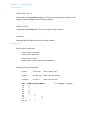
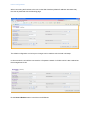
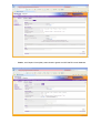
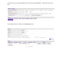
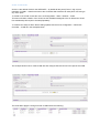
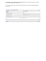
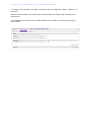
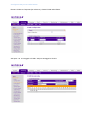
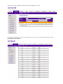
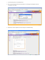
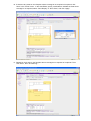
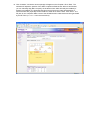
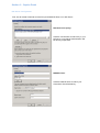
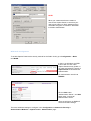
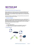
WFS709TP – Case Scenario: Wireless deployment for a Corporate and Public
network
This document describes the activities undertaken to deploy a Wireless solution using the Wireless
Controller WFS709TP and multiple Lightweight Access Points (WGL102).
The description will encompass how to create an environment with multiple SSIDs, with VLAN
separation, VLAN routing and DHCP enabled for each VLAN to serve the Wireless clients with the
relevant TCP/IP settings.
NOTE:
To ensure the configuration changes are retained in case of Power cycles please ensure
that the configuration is saved at all time using the
tab.
Table of Contents
Section 1 – Initial Setup ................................................................................................................. 2
Physical Setup ............................................................................................................................ 2
Logical setup ............................................................................................................................... 2
Initial configuration ...................................................................................................................... 4
Creating a new SSID .............................................................................................................. 5
Create a new VLAN ................................................................................................................ 8
Configure the IP address (IP Interface of a VLAN) and Enable it ..................................... 10
Configure trunk port on L2/L3 Switch .................................................................................. 11
WFS709TP trunk port configuration .................................................................................... 13
Performed testing .................................................................................................................. 13
Section 2 - RF Plan & provisioning Access Points .................................................................... 14
Section 3 – Captive Portal ........................................................................................................... 22
IAS Server Configuration ......................................................................................................... 22
WFS709TP Configuration ........................................................................................................ 23
Testing Performed .................................................................................................................... 24
Useful procedures......................................................................................................................... 25
Section 1 – Initial Setup
Physical Setup
VLAN1: Ports 1/0 – 4
Connected to the Corporate network via Trunk to a Layer2/Layer3 switch (in the
Diagram below a Netgear Layer 2/Layer 3 switch)
VLAN2: Port 1/5
Connected to the Public via a Trunk to a Layer 2/Layer 3 switch
VLAN100:
Separate the APs traffic from the rest of the network
Logical setup
APs Wireless Configuration
VLAN1: SSID = Corporate
Authentication WPA-PSK
VLAN2: SSID = Public
Authentication Captive Portal (Internal Database)
Wireless Controller Configuration:
VLAN1:
10.35.1.200
DHCP 10.35.1.0/24
VLAN2:
192.168.100.1 DHCP 192.168.100.0/24
VLAN100:
172.16.0.1
DHCP 172.16.0.0/24
Port: VLAN1 VLAN2 VLAN100
1/0
U
1/1
U
1/2
U
1/3
U
1/4
U
1/5
U
1/6
U
1/7
U
Gig 1/8
T
T
U = Untagged T= Tagged
APs Wireless configuration
Corporate
VLAN1 : SSID = Corporate
Authentication WPA-PSK
Public
VLAN2 : SSID = Public
Authentication Captive Portal (Internal DataBase)
1.2.1
1.2.2
1.2.3
1.2.4
1.2.5
1.2.6
Wireless Controller config:
POE Switch
POE Switch
VLAN1:
10.35.1.200
DHCP 10.35.1.0/24
VLAN2:
192.168.100.1
DHCP 192.168.100.0/24
VLAN100: 172.16.0.1
WFS709TP
Port:
1/0
1/1
1/2
1/3
1/4
1/5
1/6
1/7
Gig 1/8
Trunk (VLAN1, VLAN2)
VLAN1
U
U
U
U
DHCP 172.16.0.0/24
VLAN2
U
U
U
U
T
T
Layer 2/ Layer 3 switch
To Corporate Network – VLAN 1
To Public Network – VLAN 2
VLAN100
Initial configuration
When connecting the first time to the unit via the Web Interface (default IP address 192.168.0.250)
the User is presented with the following page:
The default configuration can be kept or changes can be made to suit the local LAN setup.
In this scenario the unit will be connected to a Corporate network via VLAN1 which is also retained as
the management VLAN.
Hit the Save & Reboot button is and the unit will Reboot.
The next picture shows the Network summary, after reconnecting to the unit Web Interface upon its
reboot.
Creating a new SSID
To create a new SSID access Configuration - Basic - WLAN.
In the two pictures below and as described in the Physical setup section, two SSIDs will be created:
-
Corporate, with WPA-PSK authentication (Password = 12345678 )
-
Public , with Captive Portal (Web) authentication against the WFS709TP internal database
To create Users in the Internal Database, click on Show Internal Database – Add User to add a New
user:
The example shows the creation of the Portal_Test user:
Create a new VLAN
VLAN 1 is the default VLAN for the WFS709TP – by default all the ports (Fa1/0-7, Gig 1/8) are
members of VLAN1 – therefore access to the Controller Web Interface can take place connecting to
any of the ports.
To create a new VLAN, access the menu via Configuration – Basic - Network – VLAN.
This menu will allow creation of the VLAN, but the IP address assigned to the VLAN and the VLAN
Port membership will require to be setup separately.
To combine the setup of all the above settings please use the menu Configuration – Advanced –
Controller – VLAN as in the examples below.
The example shows how to create VLAN 100 and configure Port 0/6 and 0/7 to be part of the VLAN.
The result after apply the changes to both VLANs will be the following:
This confirms the IP address assigned to the VLAN interface, what ports are members of the VLAN
and whether the Admin state is enabled or not.
In our scenario VLAN 2 will be created and port 5 associated to it, and the IP address assigned as
192.168.100.1
Configure the IP address (IP Interface of a VLAN) and Enable it
To configure the IP interface of a VLAN – access the menu at Configuration – Basic – Network – IP
Interfaces.
Edit the VLAN in question and configure the VLAN IP address and Subnet mask according to the
requirements.
This procedure may be used if the IP interface address of the VLAN is not being setup during the
VLAN creation.
Configure trunk port on L2/L3 Switch
Rename VLAN1 to Corporate (for reference). Create VLAN2 called Public.
Add ports 1 to 12 untagged to VLAN1. Add port 28 tagged to VLAN1.
Add ports 13 to 24 untagged to VLAN2. Add port 28 tagged to VLAN2.
Configure PVID settings – ports 1 to 12 with PVID of 1, ports 13 to 24 with PVID of 2. PVID on trunk
port (port 28) is not relevant.
WFS709TP trunk port configuration
Performed testing
-
Connect WFS709TP on gigabit port to FSM7328PS on port 28
Connect PC to port 1 on FSM7328PS (VLAN1)
PC obtains IP address from DHCP server on WFS709TP in the range 10.35.1.0/24
Connect laptop wirelessly to „Corporate‟ SSID
Laptop obtains IP address from DHCP server on WFS709TP in the range 10.35.1.0/24
Verify that PC can ping laptop and vice versa
Section 2 - RF Plan & provisioning Access Points
1. Starting position for this exercise: Any previously provisioned AP‟s were reset to factory
defaults and disconnected from the WFS, any previously existing buildings were deleted, old
entries were cleared from WFS database. Configuration was saved and WFS was rebooted.
2. Click on “Plan”. The following screen appears, with the default building setup which is to be
customised. Click “Building Dimension”.
3. On this screen, select “Unit” as Feet or Metres, and fill in the rest of the details. In this
example, the RF plan is only for the top floor of a 2-floor building, so “Floors” =1. Note that the
dimensions are for the full area covered by the floorplan .jpg that will be loaded at a later
step, which may be slightly larger than the area covered by the physical building. Click
“Apply”, then “AP Modelling Spec”.
4. This screen shows the default Access Point parameters.
5. Edit the default AP parameters as required. “Coverage” will calculate required number and
location of APs based on the area to be covered, while “Capacity” will calculate this based on
number of users to be supported. 100% Overlap Factor indicates that the AP coverage areas
should just touch, increasing this parameter will make roaming more reliable. The parameters
specified on this screen will determine how many APs are required. Click “Apply”, then “AM
Modelling Spec.”.
6. The Air Monitor Modelling Parameter screen determines how many AMs will be required. In
most cases, default settings will be suitable. Click “Apply”, the “Save”, then “Planning”.
7. On the Planning screen, click “Add New Floor”.
8. Fill in “Level” and “Name” text boxes, and browse to a .JPG image of the floorplan of the floor
to be added. Click “Apply”.
9. Adjust “Zoom” value to adjust the size of the image for comfortable viewing.
10. If there are any areas on the floorplan where coverage is not required or is optional, click
“New” in the “Areas” menu. In the Area Editor, specify coordinates to indicate the area where
coverage is not required, select “Don‟t Deploy” or “Don‟t Care”, and click “Apply”.
11. Repeat for each area on the floorplan where coverage is not required or is optional. Then
click “Save”, then “AP Planning”.
12. Click “Initialize”. Access points will appear on the floorplan. Click “Start”. The software will
adjust the position of the AP‟s to optimize coverage. When it has finished, you can manually
drag AP‟s to improve coverage in high-use locations like conference rooms, or to specify the
locations where AP‟s will really be installed (or already are installed). It is important that this
picture gives an accurate representation of where the APs are physically located relative to
each other. Click “Save” then “AM Planning”.
13. Click “Initialize”. Air Monitor access point(s) will appear on the floorplan. Click “Start”. The
software will adjust the position of the AM‟s to optimize effectiveness. When it has finished,
you can manually drag AM‟s to specify the locations where AM‟s will really be installed (or
already are installed). It is important that this picture gives an accurate representation of
where the AM‟s are physically located relative to each other and the AP‟s. Click “Save”. The
RF plan is now complete. Make a note of the AP/AM location codes that have been generated
by the RF Plan (1.2.1 to 1.2.6 in the screenshot).
14. Connect an access point to the network. Click on “Monitoring” in the main menu, then
“Network Summary”. Once the AP has established communication with the WFS, the
“Unprovisioned Access Point ” counter will increment and turn red.
15. Click “Maintenance”, then “Program AP”. Select an AP from the list whose Location is Not
Set. Click “Provision”.
16. Enter one of the location codes generated in the RF Plan. Click “Apply and Reboot”.
17. Connect the rest of the AP‟s to the network, and provision them one at a time.
Section 3 – Captive Portal
IAS Server Configuration
First, we will create a Remote Access Policy and RADIUS Client in our IAS Server:
Remote Access policy:
Create a new Remote Access Policy in your
IAS server, note that the authentication will
be done by simple PAP.
RADIUS Client:
Create a RADIUS Client to match your
Controller‟s IP and Shared key.
NOTE:
When you create users that are meant to
connect via Captive Portal, be sure that your
user has the option to “Store password using
reversible encryption” is ticked on. Otherwise
it will fail to authenticate.
WFS709TP Configuration
To enable Captive Portal as the security method for the Public VLAN, go to Configuration > Basic
and WLAN:
In there, we will select the SSID
that we wish to have under
Captive Portal security (Public, in
our case) and select the option of
Captive Portal under advanced
Authentication.
For authentication we will use
RADIUS.
Click on Add under
“Authentication Server”, and Add
again under “Choose an
Authentication Server”
There we will input our RADIUS
Server and Client settings.
There are additional settings to configure in the Configuration > Advanced > Security >
Authentication Methods > Captive Portal > Authentication page:
For our example, we will use
all the default settings.
Notably, HTTPS as our
protocol and no guest
access.
Also, note that the SSID is
already listed in the Match
ESSID List.
Testing Performed
Once you connect with a
wireless client to the “Public”
SSID and try to browse
anywhere, you‟ll be
redirected to the Captive
Portal page.
After inputting your
credentials, it will redirect you
to the site you were trying to
reach originally.
Useful procedures
Reset the switch to Factory Defaults:
Bring up the console and on the hyper-terminal type the following commands.
a. Reboot the box and hit enter when you see “Hit any key to stop autoboot” on the console.
b. On the cpboot prompt enter
i. cpboot > setenv cfgfile foo
ii. cpboot >saveenv
iii. boot
c. The system will reset to factory default and when it boot up it will go to the initial setup
screen.