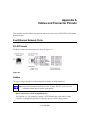
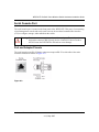
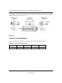
1
WFS709TP ProSafe
Smart Wireless Switch
Hardware Installation
Guide
NETGEAR, Inc.
4500 Great America Parkway
Santa Clara, CA 95054 USA
202-10264-01
May 2007
© 2007 by NETGEAR, Inc. All rights reserved.
Technical Support
Please refer to the support information card that shipped with your product. By registering your product at
http://www.netgear.com/register, we can provide you with faster expert technical support and timely notices of product
and software upgrades.
NETGEAR, INC. Support Information
Phone: 1-888-NETGEAR, for US & Canada only. For other countries, see your Support information card.
E-mail: [email protected]
North American NETGEAR website: http://www.netgear.com
Trademarks
NETGEAR and the NETGEAR logo are registered trademarks of NETGEAR, Inc. in the United States and/or other
countries. Other brand and product names are trademarks or registered trademarks of their respective holders.
Information is subject to change without notice.
Statement of Conditions
In the interest of improving internal design, operational function, and/or reliability, NETGEAR reserves the right to
make changes to the products described in this document without notice.
NETGEAR does not assume any liability that may occur due to the use or application of the product(s) or circuit
layout(s) described herein.
Certificate of the Manufacturer/Importer
It is hereby certified that the WFS709TP ProSafe™ Smart Wireless Switch has been suppressed in accordance with the
conditions set out in the BMPT-AmtsblVfg 243/1991 and Vfg 46/1992. The operation of some equipment (for example,
test transmitters) in accordance with the regulations may, however, be subject to certain restrictions. Please refer to the
notes in the operating instructions.
The Federal Office for Telecommunications Approvals has been notified of the placing of this equipment on the market
and has been granted the right to test the series for compliance with the regulations.
Bestätigung des Herstellers/Importeurs
Es wird hiermit bestätigt, daß das WFS709TP ProSafe Smart Wireless Switch gemäß der im BMPT-AmtsblVfg 243/
1991 und Vfg 46/1992 aufgeführten Bestimmungen entstört ist. Das vorschriftsmäßige Betreiben einiger Geräte (z.B.
Testsender) kann jedoch gewissen Beschränkungen unterliegen. Lesen Sie dazu bitte die Anmerkungen in der
Betriebsanleitung.
Das Bundesamt für Zulassungen in der Telekommunikation wurde davon unterrichtet, daß dieses Gerät auf den Markt
gebracht wurde und es ist berechtigt, die Serie auf die Erfüllung der Vorschriften hin zu überprüfen.
Regulatory Compliance Information
This section includes user requirements for operating this product in accordance with National laws for usage of radio
spectrum and operation of radio devices. Failure of the end user to comply with the applicable requirements may result
in unlawful operation and adverse action against the end user by the applicable National regulatory authority.
ii
v1.0, May 2007
NOTE: This product's firmware limits operation to only the channels allowed in a particular Region or Country.
Therefore, all options described in this user's guide may not be available in your version of the product.
United States
FCC Class A
This equipment has been tested and found to comply with the limits for a Class A digital device, pursuant to Part 15 of
the FCC Rules. These limits are designed to provide reasonable protection against harmful interference when the
equipment is operated in a commercial environment. This equipment generates, uses, and can radiate radio frequency
energy and, if not installed and used in accordance with the instruction manual, may cause harmful interference to radio
communications. Operation of this equipment in a residential area is likely to cause harmful interference in which case
the user will be required to correct the interference at their own expense.
Any changes or modifications not expressly approved by the party responsible for compliance could void the user’s
authority to operate this equipment.
This product is UL Listed (UL60950).
Canada
This digital apparatus does not exceed the Class A limits for radio noise emissions from digital apparatus as set out in the
interference-causing equipment standard entitled “Digital Apparatus,” ICES-003 of the Department of Communications.
Cet appareil numérique respecte les limites de bruits radioélectriques applicables aux appareils numériques de Classe A
prescrites dans la norme sur le matériel brouilleur: “Appareils Numériques,” NMB-003 édictée par le ministère des
Communications.
This product complies with CAN/CSA C22.2 No 60950 standards.
Europe
The WFS709TP ProSafe Smart Wireless Switch is compliant with the following EU Council Directives: 89/336/EEC
and LVD 73/23/EEC. Compliance is verified by testing to the following standards: EN55022 Class A, EN55024, and
EN60950.
Warning: This is a Class A product. In a domestic environment, this product may cause radio interference
in which case the user may be required to take adequate measures
Japan
This equipment is in the Class A category (information equipment to be used in commercial and/or industrial areas) and
conforms to the standards set by the Voluntary Control Council for Interference by Data Processing Equipment and
Electronic Office Machines that are aimed at preventing radio interference in commercial and/or industrial areas.
Consequently, when this equipment is used in a residential area or in an adjacent area thereto, radio interference may be
caused to equipment such as radios and TV receivers.
iii
v1.0, May 2007
VCCI - Class A
Korea
Class A
Australia/New Zealand
This product complies with AS/NZS CISPR 22 Class A standards.
Rest of World
This product complies with CISPR 22 Class A standards
.
Lithium Battery Safety Notice
This product contains a lithium battery which is replaceable only by a trained technician.
Caution: The lithium battery may explode if it is incorrectly replaced. A trained technician should replace
the battery with the same or equivalent type battery recommended by the manufacturer. Dispose of used
batteries according to the manufacturer’s instructions
iv
v1.0, May 2007
European Union RoHS
Netgear products comply with the EU Restriction of Hazardous Substances Directive
2002/95/EC (RoHS). EU RoHS restricts the use of specific hazardous materials in the
manufacture of electrical and electronic equipment. Specifically, restricted materials
under the RoHS Directive are Lead (including Solder used in printed circuit
assemblies), Cadmium, Mercury, Hexavalent Chromium, and Bromine compounds of
PBB and PBDE. Some Netgear products are subject to the exemptions listed in RoHS
Directive Annex 7 (Lead in solder used in printed circuit assemblies). Products and
packaging will be marked with the "RoHS" label shown at the left indicating
conformance to this Directive.
China RoHS
Netgear products comply with China environmental declaration requirements and are
labeled with the "EFUP 50" label shown at the left.
v
v1.0, May 2007
Product and Publication Details
Model Number:
WFS709TP
Publication Date:
May 2007
Product Family:
Wireless
Product Name:
WFS709TP ProSafe Smart Wireless Switch
Home or Business Product:
Business
Language:
English
Publication Part Number:
202-10264-01
Publication Version Number:
1.0
vi
v1.0, May 2007
Contents
About This Manual
Conventions, Formats, and Scope ................................................................................... ix
How to Use This Manual ................................................................................................... x
How to Print this Manual.................................................................................................... x
Revision History................................................................................................................ xi
Chapter 1.
Introduction
WFS709TP ProSafe Smart Wireless Switch Overview ..................................................1-1
Front and Rear View .......................................................................................................1-2
System Indicator LEDs .............................................................................................1-2
Fast Ethernet Ports ..................................................................................................1-3
GE Uplink Port .........................................................................................................1-5
Serial Console Port ..................................................................................................1-5
Fans/Heat Exhaust ...................................................................................................1-6
Rack Mounting Brackets ..........................................................................................1-6
Power Input Socket ..................................................................................................1-6
Task Overview ................................................................................................................1-6
NETGEAR Smart Wireless Components .................................................................1-6
Deployment Summary ..............................................................................................1-7
Chapter 2.
Installing the Chassis
Pre-Installation Checklist ................................................................................................2-1
Precautions .....................................................................................................................2-2
Requirements .................................................................................................................2-3
Mounting the Chassis .....................................................................................................2-4
Connecting Power ..........................................................................................................2-6
Verifying the Installation ..................................................................................................2-7
vii
v1.0, May 2007
Appendix A.
Cables and Connector Pinouts
Fast Ethernet Network Ports ......................................................................................... A-1
RJ-45 Pinouts .......................................................................................................... A-1
Cables ..................................................................................................................... A-1
GE Uplink Port ............................................................................................................... A-2
1000BASE-T (Copper) GE Cable ........................................................................... A-2
Serial Console Port ........................................................................................................ A-3
Port and Adapter Pinouts ........................................................................................ A-3
Console Terminal Settings ...................................................................................... A-4
Appendix B.
Specifications
Physical ......................................................................................................................... B-1
Environmental ................................................................................................................ B-1
Operational .................................................................................................................... B-2
Appendix C.
Related Documents
viii
v1.0, May 2007
About This Manual
The WFS709TP ProSafe™ Smart Wireless Switch Hardware Installation Guide describes how to
install the WFS709TP ProSafe Smart Wireless Switch. The information in this manual is intended
for trained technicians responsible for installing this product.
Conventions, Formats, and Scope
The conventions, formats, and scope of this manual are described in the following paragraphs:
•
•
Typographical Conventions. This manual uses the following typographical conventions:
Italic
Emphasis, books, CDs, file and server names, extensions
Bold
User input, IP addresses, GUI screen text
Fixed
Command prompt, CLI text, code
italic
URL links
Formats. This manual uses the following formats to highlight special messages:
Note: This format is used to highlight information of importance or special interest.
Tip: This format is used to highlight a procedure that will save time or resources.
Warning: Ignoring this type of note may result in a malfunction or damage to the
equipment.
ix
v1.0, May 2007
WFS709TP ProSafe Smart Wireless Switch Hardware Installation Guide
Danger: This is a safety warning. Failure to take heed of this notice may result in
personal injury or death.
•
Scope. This manual is written for the WFS709TP according to these specifications:
Product Version
WFS709TP ProSafe Smart Wireless Switch
Manual Publication Date
May 2007
For more information about network, wireless, and firewall technologies, see the links to the
NETGEAR website in Appendix C, “Related Documents”.
Note: Product updates are available on the NETGEAR, Inc. website at
http://www.netgear.com/support.
How to Use This Manual
The HTML version of this manual includes the following:
•
Buttons,
at a time
and
, for browsing forwards or backwards through the manual one page
•
A
button that displays the table of contents and an
button. Double-click on a
link in the table of contents or index to navigate directly to where the topic is described in the
manual
•
A
model
•
Links to PDF versions of the full manual and individual chapters
button to access the full NETGEAR, Inc. online knowledge base for the product
How to Print this Manual
To print this manual, choose one of the following options:
•
Printing a Page from HTML. Each page in the HTML version of the manual is dedicated to
a major topic. Select File > Print from the browser menu to print the page contents.
x
v1.0, May 2007
WFS709TP ProSafe Smart Wireless Switch Hardware Installation Guide
•
Printing from PDF. Your computer must have the free Adobe Acrobat reader installed in
order to view and print PDF files. The Acrobat reader is available on the Adobe website at
http://www.adobe.com.
– Printing a PDF Chapter. Use the PDF of This Chapter link at the top left of any page.
–
•
Click the PDF of This Chapter link at the top left of any page in the chapter you want
to print. The PDF version of the chapter you were viewing opens in a browser
window.
•
Click the print icon in the upper left of your browser window.
Printing a PDF version of the Complete Manual. Use the Complete PDF Manual link
at the top left of any page.
•
Click the Complete PDF Manual link at the top left of any page in the manual. The
PDF version of the complete manual opens in a browser window.
•
Click the print icon in the upper left of your browser window.
Tip: If your printer supports printing two pages on a single sheet of paper, you can
save paper and printer ink by selecting this feature.
Revision History
Part Number
Version
Date
Number
Description
202-10264-01
1.0
Initial NETGEAR release.
May 2007
xi
v1.0, May 2007
WFS709TP ProSafe Smart Wireless Switch Hardware Installation Guide
xii
v1.0, May 2007
Chapter 1
Introduction
The WFS709TP ProSafe Smart Wireless Switch is a full-featured wireless switch that centrally
manages NETGEAR access points, delivering integrated wireless mobility, security, and
converged services for both wired and wireless users.
This chapter contains the following topics:
•
“WFS709TP ProSafe Smart Wireless Switch Overview”
•
“Front and Rear View”
•
“Task Overview”
Once you are familiar with the system, you can begin the installation process described in the next
chapter.
WFS709TP ProSafe Smart Wireless Switch Overview
The following list identifies the key features of the WFS709TP ProSafe Smart Wireless Switch:
•
Supports up to 16 access points.
•
Eight 10/100 Mbps Fast Ethernet (FE) ports with Power over Ethernet (PoE) capability.
•
One Gigabit Ethernet (GE) uplink port.
•
One serial console port.
•
Built-in RF planning tool.
•
Wireless Intrusion Detection and Protection.
•
Advanced security features such as 802.1x, support for EAP-PEAP, EAP-TLS, EAP-TTLS,
802.11i, MAC address, SSID, and location-based authentication.
•
Unifies wireless and wired access without compromising on security, mobility, or
performance.
•
Provides centralized management and monitoring of the wireless infrastructure.
•
High-speed Layer-2/Layer-3 packet forwarding.
1-1
v1.0, May 2007
WFS709TP ProSafe Smart Wireless Switch Hardware Installation Guide
•
1U chassis can be mounted in a standard 19-inch network equipment rack.
•
The firmware can be easily upgraded as future software releases are made available. You can
install upgrades using HTTP.
Front and Rear View
The standard version of the WFS709TP ProSafe Smart Wireless Switch contains a 1000BASE-T
copper Gigabit Ethernet (GE) connector. Figure 1-1 shows the front and rear views of the switch.
Figure 1-1
System Indicator LEDs
1
The system LEDs, located on the front of the switch, display the status of system power and
operation.
Table 1-1. System LEDs
LED
State
Description
Power
Green
WFS709TP is receiving proper power.
Off
WFS709TP is powered off.
Green
WFS709TP has booted and is functioning properly.
Off
WFS709TP is booting, loading software, or has failed.
Note: This LED remains off until you perform the
initial setup described in the document Installation
Guide: WFS709TP ProSafe Smart Wireless Switch.
Status
1-2
Introduction
v1.0, May 2007
WFS709TP ProSafe Smart Wireless Switch Hardware Installation Guide
Fast Ethernet Ports
2
Use the network to connect access points (APs) as well as wired LAN segments. The ports provide
10/100 Mbps Fast Ethernet (FE) connectivity, and can provide power and serial connectivity to
compatible devices.
Power over Ethernet
Each FE port supports IEEE 802.3af Power over Ethernet (PoE).
When a compatible POE device such as the NETGEAR WAGL102 or WGL102 access point is
connected to a network port, the port can provide operating power to that device through the
connected Ethernet cable. This allows APs to be installed in areas where electrical outlets are
unavailable, undesirable, or not permitted, such as in the plenum and air-handling spaces. The
network ports automatically detect when compatible PoE devices are connected and require
power.
Special cables and adapters may be necessary to use PoE features with some equipment. See
Appendix A, “Cables and Connector Pinouts” for port and cable specifications.
Port and LED Locations
Figure 1-2 shows the FE ports and the location of the port LEDs.
Figure 1-2
FE Network Ports 1 S. The eight FE ports are split into two four-port blocks and numbered 0
through 7. Each FE port has three informational, multi-color LEDs. These LEDs are:
• LNK/ACT A
• POE B
• ACCESS POINT STATUS C
Introduction
1-3
v1.0, May 2007
WFS709TP ProSafe Smart Wireless Switch Hardware Installation Guide
Port LNK/ACT LEDs. Each FE port has its own LNK/ACT LED on the upper-left side of the
port. During operation, these LEDs provide the following Ethernet link status information:
Status
Description
Off
No Ethernet link on the port.
Green
An Ethernet link has been established on the port, but no data is currently being
transmitted or received.
Flashing Green
The port is transmitting or receiving data. The flashing rate is proportional to the
network activity.
Amber
The Ethernet link on the port is encountering errors.
Port PoE LEDs. Each FE port has its own PoE LED on the upper-right side of the port. This
LED provides the following PoE status information:
Status
Description
Off
The port is disabled, or the attached device has not requested power. PoE is not being
provided by the port.
Green
PoE is being provided to the attached device.
Amber
The attached device has requested power, but POE is not being provided by the port.
ACCESS POINT STATUS LEDs. Each FE port has an identically numbered Access Point
Status LED that represents the status of APs connected to that port on the WFS709TP ProSafe
Smart Wireless Switch. During operation, the LEDs provide the following AP status information:
Status
Description
Red (solid)
An AP on this port has failed (highest precedence).
Red (flashing)
An air monitor on this port has detected an unsecured AP. The AP is attached to your
network but is not listed in the security policies. If security policies are enabled, clients
are not granted access to your network through the unsecured AP.
Green (flashing)
An air monitor on this port has detected interference. The interfering device (AP or
other radio source) has been detected by your valid APs, but has no wired presence
on your network.
Amber (solid)
Load balancing is enabled on this port, or an AP has reached the maximum number of
clients it is configured to support.
Green (solid)
All detected APs on this port are operating as expected.
Off
No AP is detected on the port (lowest precedence).
1-4
Introduction
v1.0, May 2007
WFS709TP ProSafe Smart Wireless Switch Hardware Installation Guide
The LED states are listed in order of precedence (highest to lowest). If more than one AP is
connected to the port, the state with the highest precedence is displayed.
GE Uplink Port
3
The WFS709TP ProSafe Smart Wireless Switch provides one Gigabit Ethernet (GE) 10/100/1000
Mbps 1000BASE-T copper port for high-bandwidth connection between the switch and the wired
LAN. The port automatically senses and negotiates speed, duplex, and MDI/MDX settings.
Figure 1-3 shows the following callouts:
• Gigabit Ethernet port 1
• LNK/ACT LED, which provides the following information: 2
Status
Description
Off
No Ethernet link on the port.
Green
An Ethernet link has been established on the port, but no data is currently being
transmitted or received.
Flashing Green
The port is transmitting or receiving data. The flashing rate is proportional to your
network activity.
Figure 1-3
See “GE Uplink Port” on page A-2 for cable specifications.
Note: The Gigabit interface is not user-replaceable. Do not remove the port cover plate.
Serial Console Port
4
Use this port to connect a local management console. This connection can be used to access the
text-based command-line interface (CLI) for initial configuration of the WFS709TP.
Introduction
1-5
v1.0, May 2007
WFS709TP ProSafe Smart Wireless Switch Hardware Installation Guide
The port accepts an RS-232 serial cable with an RJ-45 male connector. See “Serial Console Port”
on page A-3 for more port and cable specifications.
Fans/Heat Exhaust
5
Three independent fans located on the side of the chassis promote proper air circulation for cooling
the WFS709TP ProSafe Smart Wireless Switch.
During operation, the air vents on the left and right sides of the chassis must remain unobstructed
by cables or mounting equipment. For proper air circulation, leave at least 10 cm (4 inches) of
clearance on the left and right of the chassis.
Rack Mounting Brackets
6
Mounting brackets are attached to each side of the chassis.
Power Input Socket
7
The power input socket on the chassis rear panel accepts a power cord with a standard IEC320
connector. For proper safety and performance, the power cord must be rated to 10 A and must
conform to grounded electrical standards in the country in which the switch operates.
Task Overview
As with any full-featured network equipment, deployment may involve multiple components as
well as various individuals in your organization. As the network manager, you should become
familiar with the components and deployment summary outlined in the following sections.
NETGEAR Smart Wireless Components
Familiarize yourself with these three major components:
•
WFS709TP Switch. This is an enterprise-class switch into which multiple access points (APs)
are connected and controlled. NETGEAR Wireless Access Points designed for small and midsized businesses with enterprise-class features can function as either access points or air
monitors.
1-6
Introduction
v1.0, May 2007
WFS709TP ProSafe Smart Wireless Switch Hardware Installation Guide
•
Wireless Access Point. The NETGEAR WAGL102 and WGL102 are designed for this
solution, and provide the best features and easiest integration. Several other NETGEAR access
point products can be repurposed to work with the WFS709TP. Refer to the NETGEAR
support site for a list of which NETGEAR APs can be repurposed, and for instructions on how
to do so. For full instructions on changing the switch’s default values, refer to the WFS709TP
ProSafe Smart Wireless Switch Software Administration Manual. The Resource CD provides a
link to this manual, or you can download it from http://www.netgear.com/support.
•
WFS709TP Software. This software integrates the switch and APs to provide load balancing,
rate limiting, self healing, authentication, mobility, encryption, and centralization for
monitoring and upgrades. This software is integrated into the switch and access point.
Deployment Summary
This section outlines the tasks involved in deploying the WFS709TP ProSafe Smart Wireless
Switch.
Note: You can download the WFS709TP ProSafe Smart Wireless Switch Software
Administration Manual from the NETGEAR website at http://www.netgear.com/
support.
1. Physical installation of the WFS709TP ProSafe Smart Wireless Switch
Installation requires a trained technician who is experienced with handling and installing
similar equipment. This phase involves the following tasks:
•
Transport, unpack, and mount the switch in a suitable rack environment.
•
Attach power and a console.
•
Boot the system and perform the initial power-on test, examining the LEDs and console
messages to ensure proper operation.
Chapter 2, “Installing the Chassis” in this document provides the necessary instructions.
2. Initial configuration of the WFS709TP ProSafe Smart Wireless Switch
Configuration requires someone who understands the company’s wired network and has
experience with the physical and logical management and configuration of routers, switches,
servers, and clients. This phase involves the following tasks:
• Use the console to perform initial configuration of the WFS709TP.
• Attach the WFS709TP to the network.
3. Planning the location of access points and air monitors
Introduction
1-7
v1.0, May 2007
WFS709TP ProSafe Smart Wireless Switch Hardware Installation Guide
You can manually determine the locations for APs, or use a Web browser to access the
switch’s built-in RF Plan tool and perform the following tasks:
• Define the physical site parameters.
• Determine how many access points are needed and where they should be located.
• Simulate network failures and recovery characteristics, and adjust placement if necessary.
4. Physical installation of the Wireless Access Points
Refer to the document Installation Guide: WFS709TP ProSafe Smart Wireless Switch and to
the documentation included with your access points.
5. Advanced configuration of the WFS709TP ProSafe Smart Wireless Switch
Configuration requires someone who understands the company’s network and has experience
managing routers, switches, servers, and clients. The following tasks are involved:
• Configure the planned network features via the Web interface.
• Test and verify the deployment.
The WFS709TP ProSafe Smart Wireless Switch Software Administration Manual provides
information and examples of the switch’s more advanced features.
1-8
Introduction
v1.0, May 2007
Chapter 2
Installing the Chassis
This chapter covers the following topics
• “Pre-Installation Checklist”
• “Precautions”
• “Requirements”
• “Mounting the Chassis”
• “Connecting Power”
• “Verifying the Installation”
Warning: Installation should be performed by a trained technician.
Pre-Installation Checklist
Inspect the package to ensure that the following components shipped with your WFS709TP
ProSafe Smart Wireless Switch:
•
WFS709TP ProSafe Smart Wireless Switch
•
Four 12-24 screws for attaching the chassis to an equipment rack
•
AC power cord rated to at least 10 A with IED320 connector
•
RS-232 serial cable with RJ-45 male connectors and serial adapter to connect the serial cable
to a terminal or PC with a DB-9 serial port
•
Ethernet cable
•
Installation Guide: WFS709TP ProSafe Smart Wireless Switch (Quick Install Guide)
•
Resource CD
•
Support Information Card
•
Warranty Card
2-1
v1.0, May 2007
WFS709TP ProSafe Smart Wireless Switch Hardware Installation Guide
During installation, you will need a Phillips or cross-head screwdriver.
Note: There should be another person available to help position the chassis.
Precautions
Observe the following precautions during installation:
•
Hazardous energy is always present while the WFS709TP is plugged into an electrical outlet.
Remove all rings, jewelry, and other potentially conductive material before working with this
product.
•
Never insert foreign objects into the chassis or any other component, even when the
WFS709TP is unpowered or unplugged.
•
Main power is fully disconnected from the WFS709TP by unplugging the power cord from the
power outlet. For safety reasons, verify that the power outlet and plug are within easy reach of
the operator.
•
Do not handle electrical cables which are not insulated. This includes any network cables.
•
To minimize electrical hazard, keep water and other fluids away from the product.
•
Comply with electrical grounding standards during all phases of installation and operation of
the product. Do not allow theWFS709TP chassis, network ports, power source, or mounting
brackets to contact any device, cable, object, or person attached to a different electrical
ground. Also, never connect the device to external storm grounding sources.
•
Installation or removal of the chassis must be performed in a static-free environment. The
proper use of anti-static body straps and mats is strongly recommended.
•
Do not ship or store this product near strong electromagnetic, electrostatic, magnetic, or
radioactive fields.
•
Do not disassemble the chassis. This product has no internal serviceable parts. When service
or repair is needed, see “Technical Support” on page ii.
2-2
Installing the Chassis
v1.0, May 2007
WFS709TP ProSafe Smart Wireless Switch Hardware Installation Guide
Requirements
The WFS709TP ProSafe Smart Wireless Switch is shipped with mounting brackets already
attached so that you can mount the chassis into a standard 19-inch equipment rack.
Note: The four 12-24 screws included with the WFS709TP are intended for securing the
chassis to the rack. Some racks require different sized screws which are not
included. Make sure that you have the correct screws or fasteners for your rack
system before attempting to mount the chassis.
The WFS709TP, like other network and computing devices, requires compliance with operational
specifications:
•
•
•
•
Reliable power
–
Make sure that your electrical outlet is compatible with the WFS709TP. For power
requirements, see Appendix B, “Specifications”.
–
Power cords must be rated to 10 A and must conform to grounded electrical standards in
the country in which the WFS709TP operates.
–
Use of a power line conditioner or Uninterruptible Power Supply (UPS) can decrease or
mitigate problems caused by power service fluctuations. Make sure that the output of any
power shaping device is compatible with the WFS709TP power supply.
Cool, non-condensing ventilation
–
For operating environment information, see Appendix B, “Specifications”.
–
Where a large number of electrical devices are running in the same area, additional air
conditioning or air circulation equipment may be required.
Ample space
–
For proper air circulation, leave at least 10 cm (4 inches) clearance for the vents on the left
and right of the chassis.
–
Leave additional space in front and back of the chassis to access power cords, network
cables, and indicator LEDs.
Limited electromagnetic interference
Installing the Chassis
2-3
v1.0, May 2007
WFS709TP ProSafe Smart Wireless Switch Hardware Installation Guide
For best operation, keep the WFS709TP and all cords and cables at least 0.7 meters (2 feet)
from fluorescent lighting fixtures, and 2 meters (6 feet) from photocopiers, radio transmitters,
electric generators, and other sources of strong electromagnetic interference. See also
Appendix B, “Specifications”.
Mounting the Chassis
This section provides instructions for installing the WFS709TP ProSafe Smart Wireless Switch.
1. Make sure that your rack environment meets the installation requirements listed on page 2-3).
2. Attach the WFS709TP to the rack, as described in the following section
Warning: To avoid personal injury or damage to equipment, get help in lifting and
positioning the WFS709TP. Also, do not install the WFS709TP where
instability or uneven mechanical loading may occur.
Note: For proper operation, make sure your rack environment is in compliance with
the operating temperatures described in Appendix B, “Specifications”.
•
Position the chassis in the equipment rack and align the brackets’ mounting holes with the
corresponding holes in your rack frame (Figure 2-1 on page 2-5).
2-4
Installing the Chassis
v1.0, May 2007
WFS709TP ProSafe Smart Wireless Switch Hardware Installation Guide
Figure 2-1
•
Use a Phillips or cross-head screwdriver to secure the chassis to the rack with two 12-24
screws (included) for each mounting bracket.
Note: Some racks require different screws which are not included. Make sure that
you use the correct screws or fasteners for your rack system.
3. Ensure that there is adequate clearance around the chassis (Figure 2-2 on page 2-6).
•
For proper air circulation, leave at least 10 cm (4 inches) clearance for the vents on the left
and right of the chassis.
•
Allow additional space in front and back of the chassis to access power cords, network
cables, and indicator LEDs.
Installing the Chassis
2-5
v1.0, May 2007
WFS709TP ProSafe Smart Wireless Switch Hardware Installation Guide
Figure 2-2
Connecting Power
Warning: This procedure should be performed by a trained technician.
1. Make sure you understand the procedure and all precautions.
Before beginning, read the entire procedure. Make sure you understand all the precautions in
these steps, as well as those listed on page 2-2.
2. Make sure that your site’s electrical system is compatible with the WFS709TP. See
Appendix B, “Specifications”.
Note: Use of a power line conditioner or Uninterruptible Power Supply (UPS) can
decrease or mitigate problems caused by power service fluctuations. Make sure
that the output of any power shaping device is compatible with the WFS709TP
power supplies.
2-6
Installing the Chassis
v1.0, May 2007
WFS709TP ProSafe Smart Wireless Switch Hardware Installation Guide
3. Make sure that the power supply can handle the connected Power over Ethernet (PoE) devices.
Note: The total power drawn by all connected PoE devices must not exceed 100
Watts. For power ratings for NETGEAR APs, refer to the access point
installation guide.
4. Attach the power cord to the power input socket at the back of the chassis.
Plug an appropriate power cord into the power input socket. Use the included power cord if it
is compatible with your electrical outlet. Otherwise, replace the power cord with the type
appropriate for your country. The power input socket accepts a power cord with a standard
IEC320 connector.
Warning: For proper safety and performance, the power cord must be rated to 10 A
and conform to grounded electrical standards in the country where the
product is operated.
5. Attach the power cord to a proper electrical outlet to power up the WFS709TP.
Warning: For safety reasons, make sure the power outlet and plug are within easy
reach of the operator and can be quickly disconnected if necessary.
Once power is connected, the WFS709TP automatically turns on and you can perform the
power-on test.
Verifying the Installation
After the WFS709TP ProSafe Smart Wireless Switch is installed and connected to power, verify
the following:
1. Check that the Power LED lights solid green immediately upon power up and remains solid
green during and after boot.
Note: The Status LED remains off until you perform the initial setup.
Installing the Chassis
2-7
v1.0, May 2007
WFS709TP ProSafe Smart Wireless Switch Hardware Installation Guide
For more information on LED behavior, see “System Indicator LEDs” on page 1-2.
2. Check the fans to verify they are working.
You should be able to hear the fans operating and feel significant airflow blowing from the
chassis vents at each of the three fan positions.
Warning: If one or more fans do not work, immediately shut down and contact
NETGEAR.
3. Connect appropriate network cables (see Appendix A, “Cables and Connector Pinouts” for
port and cable information).
4. Perform the initial setup as described in Installation Guide: WFS709TP ProSafe Smart
Wireless Switch.
2-8
Installing the Chassis
v1.0, May 2007
Appendix A
Cables and Connector Pinouts
This appendix describes cables and connector pinouts for ports on the WFS709TP ProSafe Smart
Wireless Switch.
Fast Ethernet Network Ports
RJ-45 Pinouts
The RJ-45 female connector pinouts are shown in Figure A-1:
Figure A-1
Cables
The type of cable required for each port depends on the device being connected.
Note: Refer to the document Installation Guide: ProSafe Wireless Access Point for
information about specific power requirements.
•
Direct connection to a POE-compatible device
This requires a 4- or 8-conductor Category 5 UTP Ethernet cable with an RJ-45 male
connector. A straight-through cable is required to preserve POE voltage polarity.
Cables and Connector Pinouts
A-1
v1.0, May 2007
WFS709TP ProSafe Smart Wireless Switch Hardware Installation Guide
For PoE, the port should be connected directly to the intended device with no intervening
hubs, routers, switches, or other network equipment.
•
Connection to a regular 10/100 Mbps Ethernet segment
This requires a 4- or 8-conductor Category 5 UTP Ethernet cable with an RJ-45 male
connector. The port detects MDI/MDX and automatically adjusts for straight-through or
crossover cables.
The maximum length for FE cables is 100 meters (325 feet).
Cables that run through plenums or air-handling spaces as described in NEC (2002) Article
300.22(C) should be suitable under NEC Article 800.50 and marked accordingly for use in
plenums and air-handling spaces with regard to smoke propagation, such as CL2-P, CL3-P, MPP,
or CMP.
Note: Be sure to install cables in accordance with all applicable local regulations and
practices.
GE Uplink Port
1000BASE-T (Copper) GE Cable
Table A-1 lists the cable characteristics for the 1000BASE-T GE uplink port.
Table A-1. Copper GE Cable Characteristics
Item
Specification
Cable
Category 5 UTP
Connector
RJ-45
Range
Up to 100 m (325 feet)
A-2
Cables and Connector Pinouts
v1.0, May 2007
WFS709TP ProSafe Smart Wireless Switch Hardware Installation Guide
Serial Console Port
The serial console port is located on the front panel of the WFS709TP. This port is for connecting
a local management console and can be used to access the text-based command-line interface
(CLI) to configure, manage, and troubleshoot the switch.
Warning: Do not connect access points to the serial console port. The serial port is
designed to connect to RS-232-only devices. Non-RS-232 devices such as
APs will cause the WFS709TP to fail and can cause damage.
Port and Adapter Pinouts
The serial console port’s RJ-45 female connector accepts an RS-232 serial cable with a male
connector. Pinouts are shown in Figure A-2:
Figure A-2
Cables and Connector Pinouts
A-3
v1.0, May 2007
WFS709TP ProSafe Smart Wireless Switch Hardware Installation Guide
To connect the required RS-232 serial cable to a terminal with a DB-9 male port, use the included
adapter. Pinouts are shown in Figure A-3:
Figure A-3
Console Terminal Settings
Table A-2 contains the settings for a console terminal connected to the serial port.
Table A-2. Console Terminal Settings
Baud Rate
Data Bits
Parity
Stop Bits
Flow Control
9600
8
None
1
None
A-4
Cables and Connector Pinouts
v1.0, May 2007
Appendix B
Specifications
Physical
Table B-1. Physical Specifications
Item
Specification
Physical Dimensions:
Size
Height 4.45 cm (1.75 inches)
Width 44.2 cm (17.4 inches)
Depth 33.0 cm (13.0 inches)
Weight
4.5 kg (10 lb)
Shipping Dimensions:
Size
Height 25.4 cm (10 inches)
Width 60.96 cm (24 inches)
Depth 55.88 cm (22 inches)
Weight
8.62 kg (19 lb)
Environmental
Table B-2. Environmental Specifications
Item
Specification
Temperature
Operating: 0 to 40 ºC (32 to 104 ºF)
Storage: 0 to 50 ºC (32 to 122 ºF)
Humidity
5% to 95% (non-condensing)
Altitude
Up to 10,000 feet (3048 m)
Specifications
B-1
v1.0, May 2007
WFS709TP ProSafe Smart Wireless Switch Hardware Installation Guide
Operational
Table B-3. Operational Specifications
Item
Specification
Power Consumption
170 Watts, maximum
AC Input Voltage
90~132VAC, 180-264VAC, auto-sensing
AC Input Current
4A @ 110VAC
AC Input Frequency
47-63 Hz
Output Voltage
48VDC 802.3af (maximum aggregate power draw for PoE is 100 Watts)
Standards
IEEE 802.1x, IEEE 802.3 10BASE-T, IEEE 802.3u 100BASE-TX,
IEEE 802.3ab 1000BASE-T
B-2
Specifications
v1.0, May 2007
Appendix C
Related Documents
This appendix provides links to reference documents you can use to gain a more complete
understanding of the technologies used in your NETGEAR product.
Document
Link
Internet Networking and TCP/IP
Addressing
http://documentation.netgear.com/reference/enu/tcpip/index.htm
Wireless Communications
http://documentation.netgear.com/reference/enu/wireless/index.htm
Preparing a Computer for
Network Access
http://documentation.netgear.com/reference/enu/wsdhcp/index.htm
Glossary
http://documentation.netgear.com/reference/enu/glossary/index.htm
Related Documents
C-1
v1.0, May 2007
WFS709TP ProSafe Smart Wireless Switch Hardware Installation Guide
C-2
Related Documents
v1.0, May 2007