1
FS728TP Smart Switch
Software User Manual
NETGEAR, Inc.
4500 Great America Parkway
Santa Clara, CA 95054 USA
202-10231-01
November 2006
© 2005 by NETGEAR, Inc. All rights reserved. FullManual.
Trademarks
NETGEAR , the NETGEAR logo, and Auto Uplink are trademarks or registered trademarks of NETGEAR, Inc.
Microsoft, Windows, and Windows NT are registered trademarks of Microsoft Corporation.
Other brand and product names are registered trademarks or trademarks of their respective holders. Portions of this
document are copyright Intoto, Inc.
November 2006
Statement of Conditions
In the interest of improving internal design, operational function, and/or reliability, NETGEAR reserves the right to
make changes to the products described in this document without notice.
NETGEAR does not assume any liability that may occur due to the use or application of the product(s) or circuit
layout(s) described herein.
Certificate of the Manufacturer/Importer
It is hereby certified that the FS728TP Prosafe 24 10/100 Smart Switch with 4 Gigabit ports and PoE has been
suppressed in accordance with the conditions set out in the BMPT-AmtsblVfg 243/1991 and Vfg 46/1992. The operation
of some equipment (for example, test transmitters) in accordance with the regulations may, however, be subject to
certain restrictions. Please refer to the notes in the operating instructions.
The Federal Office for Telecommunications Approvals has been notified of the placing of this equipment on the market
and has been granted the right to test the series for compliance with the regulations.
Bestätigung des Herstellers/Importeurs
Es wird hiermit bestätigt, daß das FS728TP Prosafe 24 10/100 Smart Switch with 4 Gigabit ports and PoE gemäß der im
BMPT-AmtsblVfg 243/1991 und Vfg 46/1992 aufgeführten Bestimmungen entstört ist. Das vorschriftsmäßige Betreiben
einiger Geräte (z.B. Testsender) kann jedoch gewissen Beschränkungen unterliegen. Lesen Sie dazu bitte die
Anmerkungen in der Betriebsanleitung.
Das Bundesamt für Zulassungen in der Telekommunikation wurde davon unterrichtet, daß dieses Gerät auf den Markt
gebracht wurde und es ist berechtigt, die Serie auf die Erfüllung der Vorschriften hin zu überprüfen.
Voluntary Control Council for Interference (VCCI) Statement
This equipment is in the Class B category (information equipment to be used in a residential area or an adjacent area
thereto) and conforms to the standards set by the Voluntary Control Council for Interference by Data Processing
Equipment and Electronic Office Machines aimed at preventing radio interference in such residential areas. When used
near a radio or TV receiver, it may become the cause of radio interference. Read instructions for correct handling.
Note: Delete this note and the information below for products that are not wireless.
ii
v2.0, November 2006
Regulatory Compliance Information
This section includes user requirements for operating this product in accordance with National laws for usage of radio
spectrum and operation of radio devices. Failure of the end-user to comply with the applicable requirements may result
in unlawful operation and adverse action against the end-user by the applicable National regulatory authority.
NOTE: This product's firmware limits operation to only the channels allowed in a particular Region or Country.
Therefore, all options described in this user's guide may not be available in your version of the product.
Europe – EU Declaration of Conformity
Marking by the above symbol indicates compliance with the Essential Requirements of the R&TTE Directive of the
European Union (1999/5/EC). This equipment meets the following conformance standards:
EN300 328, EN301 489-17, EN60950
Europe – Declaration of Conformity in Languages of the European Community
Cesky [Czech]
NETGEAR Inc. tímto prohlašuje, že tento Radiolan je ve shode se základními
požadavky a dalšími príslušnými ustanoveními smernice 1999/5/ES..
Dansk
[Danish]
Undertegnede NETGEAR Inc. erklærer herved, at følgende udstyr Radiolan overholder
de væsentlige krav og øvrige relevante krav i direktiv 1999/5/EF.
Deutsch
[German]
Hiermit erklärt NETGEAR Inc., dass sich das Gerät Radiolan in Übereinstimmung mit
den grundlegenden Anforderungen und den übrigen einschlägigen Bestimmungen der
Richtlinie 1999/5/EG befindet.
Eesti
[Estonian]
Käesolevaga kinnitab NETGEAR Inc. seadme Radiolan vastavust direktiivi 1999/5/EÜ
põhinõuetele ja nimetatud direktiivist tulenevatele teistele asjakohastele sätetele.
English
Hereby, NETGEAR Inc., declares that this Radiolan is in compliance with the essential
requirements and other relevant provisions of Directive 1999/5/EC.
Español
[Spanish]
Por medio de la presente NETGEAR Inc. declara que el Radiolan cumple con los
requisitos esenciales y cualesquiera otras disposiciones aplicables o exigibles de la
Directiva 1999/5/CE.
Ελληνική
[Greek]
ΜΕ ΤΗΝ ΠΑΡΟΥΣΑ NETGEAR Inc. ΔΗΛΩΝΕΙ ΟΤΙ Radiolan ΣΥΜΜΟΡΦΩΝΕΤΑΙ
ΠΡΟΣ ΤΙΣ ΟΥΣΙΩΔΕΙΣ ΑΠΑΙΤΗΣΕΙΣ ΚΑΙ ΤΙΣ ΛΟΙΠΕΣ ΣΧΕΤΙΚΕΣ ΔΙΑΤΑΞΕΙΣ ΤΗΣ
ΟΔΗΓΙΑΣ 1999/5/ΕΚ.
Français
[French]
Par la présente NETGEAR Inc. déclare que l'appareil Radiolan est conforme aux
exigences essentielles et aux autres dispositions pertinentes de la directive 1999/5/CE.
Italiano [Italian]
Con la presente NETGEAR Inc. dichiara che questo Radiolan è conforme ai requisiti
essenziali ed alle altre disposizioni pertinenti stabilite dalla direttiva 1999/5/CE.
Latviski
[Latvian]
Ar šo NETGEAR Inc. deklarē, ka Radiolan atbilst Direktīvas 1999/5/EK būtiskajām
prasībām un citiem ar to saistītajiem noteikumiem.
iii
v2.0, November 2006
Lietuvių
[Lithuanian]
Šiuo NETGEAR Inc. deklaruoja, kad šis Radiolan atitinka esminius reikalavimus ir kitas
1999/5/EB Direktyvos nuostatas.
Nederlands
[Dutch]
Hierbij verklaart NETGEAR Inc. dat het toestel Radiolan in overeenstemming is met de
essentiële eisen en de andere relevante bepalingen van richtlijn 1999/5/EG.
Malti [Maltese]
Hawnhekk, NETGEAR Inc., jiddikjara li dan Radiolan jikkonforma mal-htigijiet
essenzjali u ma provvedimenti ohrajn relevanti li hemm fid-Dirrettiva 1999/5/EC.
Magyar
[Hungarian]
Alulírott, NETGEAR Inc. nyilatkozom, hogy a Radiolan megfelel a vonatkozó alapvetõ
követelményeknek és az 1999/5/EC irányelv egyéb elõírásainak.
Polski [Polish]
Niniejszym NETGEAR Inc. oświadcza, że Radiolan jest zgodny z zasadniczymi
wymogami oraz pozostałymi stosownymi postanowieniami Dyrektywy 1999/5/EC.
Português
[Portuguese]
NETGEAR Inc. declara que este Radiolan está conforme com os requisitos essenciais
e outras disposições da Directiva 1999/5/CE.
Slovensko
[Slovenian]
NETGEAR Inc. izjavlja, da je ta Radiolan v skladu z bistvenimi zahtevami in ostalimi
relevantnimi določili direktive 1999/5/ES.
Slovensky
[Slovak]
NETGEAR Inc. týmto vyhlasuje, _e Radiolan spĺňa základné po_iadavky a všetky
príslušné ustanovenia Smernice 1999/5/ES.
Suomi
[Finnish]
NETGEAR Inc. vakuuttaa täten että Radiolan tyyppinen laite on direktiivin 1999/5/EY
oleellisten vaatimusten ja sitä koskevien direktiivin muiden ehtojen mukainen.
Svenska
[Swedish]
Härmed intygar NETGEAR Inc. att denna Radiolan står I överensstämmelse med de
väsentliga egenskapskrav och övriga relevanta bestämmelser som framgår av direktiv
1999/5/EG.
Íslenska
[Icelandic]
Hér með lýsir NETGEAR Inc. yfir því að Radiolan er í samræmi við grunnkröfur og aðrar
kröfur, sem gerðar eru í tilskipun 1999/5/EC.
Norsk
[Norwegian]
NETGEAR Inc. erklærer herved at utstyret Radiolan er i samsvar med de
grunnleggende krav og øvrige relevante krav i direktiv 1999/5/EF.
FCC Requirements for Operation in the United States
FCC Information to User
This product does not contain any user serviceable components and is to be used with approved antennas only. Any
product changes or modifications will invalidate all applicable regulatory certifications and approvals
FCC Guidelines for Human Exposure
This equipment complies with FCC radiation exposure limits set forth for an uncontrolled environment. This equipment
should be installed and operated with minimum distance of 20 cm between the radiator and your body.
This transmitter must not be co-located or operating in conjunction with any other antenna or transmitter.
iv
v2.0, November 2006
FCC Declaration Of Conformity
We NETGEAR, Inc., 4500 Great America Parkway, Santa Clara, CA 95054, declare under our sole responsibility that
the model FS728TP Prosafe 24 10/100 Smart Switch with 4 Gigabit ports and PoE complies with Part 15 of FCC Rules.
Operation is subject to the following two conditions:
•
This device may not cause harmful interference, and
•
This device must accept any interference received, including interference that may cause undesired operation.
Product and Publication Details
Model Number:
FS728TP
Publication Date:
November 2006
Product Family:
SmartSwitch
Product Name:
FS728TP Prosafe 24 10/100 Smart Switch with 4 Gigabit ports and PoE
Home or Business Product:
Business
Language:
English
Publication Part Number:
202-10231-01
Publication Version Number:
2.0
v
v2.0, November 2006
vi
v2.0, November 2006
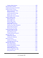
Contents
About This Manual
Conventions, Formats and Scope .................................................................................... xi
How to Use This Manual ..................................................................................................xii
How to Print this Manual ...................................................................................................xii
Chapter 1
Switch Management Overview
Chapter 2
Getting Started
Network with DHCP server .............................................................................................2-1
Network without DHCP server ........................................................................................2-4
Chapter 3
Smartwizard Discovery Program
Main Screen ...................................................................................................................3-1
Main Screen > Device List > Discover .....................................................................3-3
Main Screen: Device List > Discover .......................................................................3-4
Main Screen > Switch Setting > Configuration Setting ............................................3-5
Main Screen > Device Setting > Configuration Setting > Set ..................................3-5
Main Screen > Device Setting > Configuration Setting > Cancel .............................3-6
Main Screen> > Switch Setting> > Password Change ............................................3-6
Main Screen > Switch Setting > Web Access ..........................................................3-7
Main Screen > Switch Setting > Firmware Upgrade ................................................3-8
Main Screen > Switch Setting > Exit ........................................................................3-9
Chapter 4
Software Upgrade Procedure
Chapter 5
Configuring the Device Using Your Browser
Getting Started ................................................................................................................5-2
Opening the NETGEAR FS728TP Web Interface ....................................................5-2
Understanding the Web Interface ............................................................................5-3
vii
v2.0, November 2006
Device Management Buttons ...................................................................................5-5
Resetting the System .....................................................................................................5-6
Defining Device Information ...........................................................................................5-7
Viewing the Device Zoom View ................................................................................5-8
Viewing the Device Information ................................................................................5-9
Configuring System Time .......................................................................................5-10
Configuring Device Security .........................................................................................5-13
Defining Port Authentication Properties .................................................................5-14
Defining Port Authentication ...................................................................................5-16
Viewing EAP Statistics ...........................................................................................5-19
Enabling Storm Control ..........................................................................................5-21
ACL Overview ...............................................................................................................5-24
Defining MAC Based Access Control Lists ............................................................5-24
Defining Access Control Lists Binding ...................................................................5-28
Port Based Security ......................................................................................................5-30
Configuring Passwords ..........................................................................................5-34
Defining RADIUS Settings ............................................................................................5-36
Defining TACACS+ Authentication ...............................................................................5-38
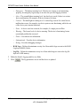
Viewing System Logs ...................................................................................................5-41
Logs Configuration .................................................................................................5-42
Viewing the Memory Logs ......................................................................................5-44
Viewing the Flash Logs ..........................................................................................5-45
Viewing Server Logs ..............................................................................................5-46
Configuring Power over Ethernet .................................................................................5-48
Configuring Interfaces ..................................................................................................5-55
Defining Port Parameters .......................................................................................5-55
Defining LAG Members ..........................................................................................5-59
Viewing LAG Membership ......................................................................................5-65
Configuring LACP ..................................................................................................5-67
Configuring VLANs .......................................................................................................5-68
Defining VLAN Properties ......................................................................................5-69
Defining VLAN Membership ...................................................................................5-72
Defining VLAN PVID Settings ................................................................................5-74
Defining IP Interfaces ...................................................................................................5-75
Defining the Forwarding Address Tables ......................................................................5-77
viii
v2.0, November 2006
Configuring Static Addresses .................................................................................5-78
Defining Dynamic Addresses .......................................................................................5-80
Configuring the Spanning Tree Protocol .......................................................................5-82
Configuring Quality of Service ......................................................................................5-87
Defining General QoS Settings ..............................................................................5-88
Defining QoS Queues ............................................................................................5-90
Configuring Bandwidth Settings .............................................................................5-91
Mapping CoS to Queues ........................................................................................5-94
Mapping DSCP Values to Queues .........................................................................5-95
Configuring SNMP Security ..........................................................................................5-96
Defining the Engine ID ...........................................................................................5-97
Defining SNMP Users ............................................................................................5-98
Defining SNMP Groups ........................................................................................5-101
Configuring SNMP Views .....................................................................................5-105
Defining SNMP Communities ...............................................................................5-107
Configuring Trap Station Management ................................................................ 5-111
Defining Global Trap Settings .............................................................................. 5-116
Defining Trap Filter Settings ................................................................................. 5-117
Configuring Multicast Forwarding ............................................................................... 5-119
Configuring IGMP Snooping ................................................................................5-120
Defining Multicast Groups ....................................................................................5-123
Configuring Multicast Forward All ........................................................................5-126
Managing System Files ..............................................................................................5-128
Configuring File Uploads ......................................................................................5-129
Configuring File Downloads .................................................................................5-130
Monitoring the Device .................................................................................................5-132
Configuring Port Mirroring ....................................................................................5-133
Performing Copper Cable Tests ...........................................................................5-136
Managing RMON Statistics .........................................................................................5-138
Viewing RMON Statistics .....................................................................................5-138
Resetting RMON Statistics Counters ...................................................................5-140
Configuring RMON History ...................................................................................5-140
Defining RMON History Control ...........................................................................5-140
Viewing the RMON History Table .........................................................................5-144
Defining RMON Events ........................................................................................5-146
ix
v2.0, November 2006
Defining RMON Alarms ........................................................................................5-150
Resetting to Factory Default Values ...........................................................................5-154
x
v2.0, November 2006
About This Manual
The NETGEAR® FS728TP Smart Switch Reference Manual describes how to install, configure
and troubleshoot the FS728TP Prosafe 24 10/100 Smart Switch with 4 Gigabit ports and PoE. The
information in this manual is intended for readers with intermediate computer and Internet skills.
Conventions, Formats and Scope
The conventions, formats, and scope of this manual are described in the following paragraphs:
•
•
Typographical Conventions. This manual uses the following typographical conventions:
Italics
Emphasis, books, CDs, URL names
Bold
User input
Fixed
Screen text, file and server names, extensions, commands, IP addresses
Formats. This manual uses the following formats to highlight special messages:
Note: This format is used to highlight information of importance or special interest.
Tip: This format is used to highlight a procedure that will save time or resources.
Warning: Ignoring this type of note may result in a malfunction or damage to the
equipment.
Danger: This is a safety warning. Failure to take heed of this notice may result in
personal injury or death.
xi
v2.0, November 2006
•
Scope. This manual is written for the FVX538 VPN firewall according to these specifications:
Product Version
FS728TP Prosafe 24 10/100 Smart Switch with 4 Gigabit ports and
PoE
Manual Publication Date
November 2006
Note: Product updates are available on the NETGEAR, Inc. website at
http://kbserver.netgear.com/products/FS728TP.asp.
How to Use This Manual
The HTML version of this manual includes the following:
•
Buttons,
at a time
and
, for browsing forwards or backwards through the manual one page
•
A
button that displays the table of contents and an
button. Double-click on a
link in the table of contents or index to navigate directly to where the topic is described in the
manual.
•
A
model.
•
Links to PDF versions of the full manual and individual chapters.
button to access the full NETGEAR, Inc. online knowledge base for the product
How to Print this Manual
To print this manual you can choose one of the following several options, according to your needs.
•
Printing a Page in the HTML View. Each page in the HTML version of the manual is
dedicated to a major topic. Use the Print button on the browser toolbar to print the page
contents.
•
Printing a Chapter. Use the PDF of This Chapter link at the top left of any page.
– Click the PDF of This Chapter link at the top right of any page in the chapter you want to
print. The PDF version of the chapter you were viewing opens in a browser window.
xii
v2.0, November 2006
–
–
Your computer must have the free Adobe Acrobat reader installed in order to view and
print PDF files. The Acrobat reader is available on the Adobe Web site at
http://www.adobe.com.
Click the print icon in the upper left of the window.
Tip: If your printer supports printing two pages on a single sheet of paper, you can
save paper and printer ink by selecting this feature.
•
Printing the Full Manual. Use the Complete PDF Manual link at the top left of any page.
–
Click the Complete PDF Manual link at the top left of any page in the manual. The PDF
version of the complete manual opens in a browser window.
–
Click the print icon in the upper left of the window.
Tip: If your printer supports printing two pages on a single sheet of paper, you can
save paper and printer ink by selecting this feature.
xiii
v2.0, November 2006
FS728TP Smart Switch Software User Manual
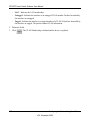
Chapter 1
Switch Management Overview
This chapter provides an overview of switch management, including the methods for managing the
NETGEAR FS728TP family of 10/100 Mbps Port Smart Fast Ethernet Switches with Gigabit
Ports and PoE.
The family of ProSafe Smart Switches is designed for growing businesses that want control over
their network without the cost and complexity of a full Layer 2/Layer 3 management
implementation. This PoE capable Smart Switch, the FS728TP, provides power and data using
built-in IEEE 802.3af PoE on all 24 ports.
The NETGEAR FS728TP family of 10/100 Mbps Port Smart Fast Ethernet Switches with Gigabit
Ports contains software for viewing, changing, and monitoring the device. This management
software is not required for the switch to work. You can use the 10/100 Mbps ports and the built-in
Gigabit ports without using the management software. However, the management software allows
you configure ports, device features, and improve the switch’s efficiency. The management
software improves the network’s performance. The Switch provides additional network flexibility
for accessing and managing the switch using the following methods:
•
Smartwizard Discovery program
•
Web browser interface
1-xiv
Switch Management Overview
v2.0, November 2006
FS728TP Smart Switch Software User Manual
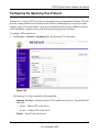
After you power-up the switch for the first time, you can configure it using a utility program called
SmartWizard Discovery or a Web browser. Please refer to the screenshots in the following pages
for Smartwizard Discovery and Web Management GUI appearance. Each of these management
methods has advantages.
Table 1:
Comparing Switch Management Methods
Management Method
Advantages
Smartwizard Discovery
program
No IP address or subnet needed
Show all switches on the network
User-friendly interface
Firmware upgradeable
Web browser
Can be accessed from any location via the switch’s IP address
Password protected
Ideal for configuring the switch remotely
Compatible with Internet Explorer and Netscape Navigator Web browsers
Intuitive browser interface
Most visually appealing
Extensive switch configuration allowed
Configuration backup for duplicating settings to other switches
For a more detailed discussion of the Smartwizard Discovery Program, see Chapter 3 For a more
detailed discussion of the Web Browser Interface, see Chapter 5
Switch Management Overview
1-xv
v2.0, November 2006
FS728TP Smart Switch Software User Manual
Chapter 2
Getting Started
This chapter walks you through the steps to start managing your FS728TP switch. This chapter
covers how to get started in a network with a DHCP server (most common) as well as in a network
that does not have a DHCP server.
Network with DHCP server
1. Connect the FS728TP switch to a DHCP network.
2. Power on the FS728TP switch by plugging in a power cord.
3. Install the Smartwizard Discovery program on your computer.
4. Start the Smartwizard Discovery program. (Chapter 3 has detailed instructions on the
Smartwizard Discovery).
5. Click Discover for the Smartwizard Discovery to find your FS728TP switch.
2-1
Getting Started
v3.0, November 2006
FS728TP Smart Switch Software User Manual
Figure 2-1
6. Select your switch by clicking on it. Then click on Web Access, see Figure 2-2.
Getting Started
2-2
v3.0, November 2006
FS728TP Smart Switch Software User Manual
Figure 2-2
7. Start managing your switch via your web browser. The default password is password. For a
detailed description on web management, please refer to Configuring the Device Using Your
Browser .
2-3
Getting Started
v3.0, November 2006
FS728TP Smart Switch Software User Manual
Network without DHCP server
A static IP address can be assigned to the FS728TP device, even if the network does not have a
DHCP server.
1. Connect the FS728TP switch to your existing network.
2. Power on the FS728TP switch by plugging in a power cord.
3. Install the Smartwizard Discovery program on your computer
4. Start Smartwizard Discovery. (Chapter 3 has detailed instructions on the Smartwizard
Discovery)
5. Click Discover for the Smartwizard Discovery to find your FS728TP switch.
6. Click on Configuration Setting (See Figure 2-3).
Figure 2-3
7. Choose the Disable option on DHCP selection. See Figure 2-3.
Getting Started
2-4
v3.0, November 2006
FS728TP Smart Switch Software User Manual
8. The default IP address is set as 192.168.0.239 with subnet mask ????. If you want different
values, enter your IP address, gateway address and subnet mask values, and then type your
password and click Set. Please make sure your PC and FS728TP switch are in the same subnet
(See Figure 2-4).
Figure 2-4
9. Select your switch by clicking on it. Then click on Web Access, see Figure 2-2.
10. Start managing your switch via your web browser. The default password is password. For a
detailed description on web management access, please refer to Chapter 5.
2-5
Getting Started
v3.0, November 2006
FS728TP Smart Switch Software User Manual
Figure 2-5
Getting Started
2-6
v3.0, November 2006
FS728TP Smart Switch Software User Manual
Chapter 3
Smartwizard Discovery Program
The Smartwizard Discovery program is a user-friendly, easy to install tool. Using this program,
you can view and configure all the FS728TP Smart Switches in your network.
The installation of the Smartwizard Discovery is as follows:
1. Insert the disc into your CD-ROM drive.
2. Select the Software folder or click Install from the Browser window that automatically
appears after inserting the Resource CD.
3. Run the Setup program to install the Smartwizard Discovery.
4. The Installation Wizard will guide you through the subsequent steps.
5. Run Smartwizard Discovery from the window start bar.
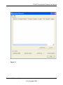
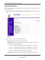
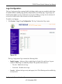
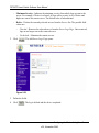
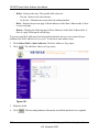
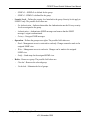
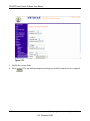
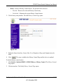
Main Screen
The main screen displays the available functions. As shown in Figure 3-1, there are six function
items to choose from:
•
Discover
•
Configuration Setting
•
Password Change
•
Web Access
•
Firmware Upgrade
•
Exit
3-1
Smartwizard Discovery Program
v2.0, November 2006
FS728TP Smart Switch Software User Manual
Figure 3-1
Smartwizard Discovery Program
3-2
v2.0, November 2006
FS728TP Smart Switch Software User Manual
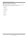
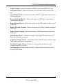
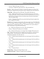
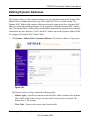
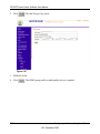
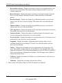
Main Screen > Device List > Discover
The Smartwizard Discovery can discover all switches currently active on the network. Click
Discover to view the following switch information of any listed switch:
•
MAC Address
•
IP Address
•
Protocol Version
•
Product Name
•
System Name
•
Location
•
DHCP
•
Subnet Mask
•
Gateway.
3-3
Smartwizard Discovery Program
v2.0, November 2006
FS728TP Smart Switch Software User Manual
Figure 3-2
Main Screen: Device List > Discover
By double-clicking a listed switch, you can open the Web management for that switch.
Alternatively, you can select a switch by clicking on it once, and then clicking Web Access. For
more information on Web management, see Chapter 5.
Smartwizard Discovery Program
3-4
v2.0, November 2006
FS728TP Smart Switch Software User Manual
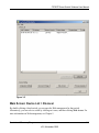
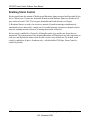
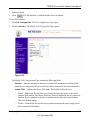
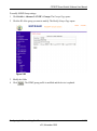
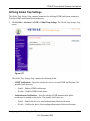
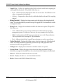
Main Screen > Switch Setting > Configuration Setting
Select a switch by clicking on it. Then click Configuration Setting. The following screen appears.
From this screen, you can modify:.
Figure 3-3
•
IP Address – Displays the currently configured IP address.
•
Subnet Mask – Displays the currently configured Subnet Mask.
•
Gateway – Displays the currently configured Gateway.
•
System Name – Provides a user-defined system name field. The System Name field is to help
you keep track of your switches. The field can contain any combination of letters and
numbers.
•
Location – Provides a user-defined field is to help you keep track of where this switch is. It
can contain any combination of letters and numbers.
•
Password – Displays the default password is ‘password’.
•
DHCP – DHCP automatically obtains the IP information for the switch.
•
Product Name – Displays the Product Name.
•
Mac Address – Displays the device MAC address.
Main Screen > Device Setting > Configuration Setting > Set
Click Set to enable the new settings. You must enter your password for these settings to be
accepted.
3-5
Smartwizard Discovery Program
v2.0, November 2006
FS728TP Smart Switch Software User Manual
Main Screen > Device Setting > Configuration Setting > Cancel
Click Cancel to abort the above settings.
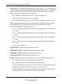
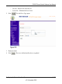
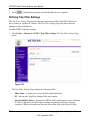
Main Screen> > Switch Setting> > Password Change
1. Click Password Change from the Switch Setting chapter. The following screen appears as
shown in Figure 3-4.
Figure 3-4
•
New Password – Type any desired password. Passwords are case-sensitive and can have a
maximum of 20 characters.
•
Confirm Password – Re-type the new password to confirm it.
•
Old Password – The default password is ‘password’.
2. Click Set to enable new password.
Smartwizard Discovery Program
3-6
v2.0, November 2006
FS728TP Smart Switch Software User Manual
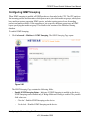
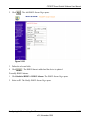
Main Screen > Switch Setting > Web Access
Figure 3-5
3. Select a listed switch from the Device List chapter. Then click Web Access from the Switch
Setting, see Figure 3-2.
4. Enter the default password and click Log in. For more on Web management, see Chapter 5
3-7
Smartwizard Discovery Program
v2.0, November 2006
FS728TP Smart Switch Software User Manual
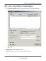
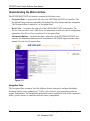
Main Screen > Switch Setting > Firmware Upgrade
1. Click Firmware Upgrade from the Switch Settings chapter. The following screen opens:
Figure 3-6
•
Product Name - Displays the Product Name.
•
Product IP Address - Displays the product configured IP address.
Smartwizard Discovery Program
3-8
v2.0, November 2006
FS728TP Smart Switch Software User Manual
•
Product Assigned Firmware -The location of the new firmware. If you do not know where to
find it, click Browse to locate it.
•
Upgrade Password - The default password is 'password'.
•
Upgrade State - Shows upgrading in progress.
2. Click Start Upgrade to start upgrading.
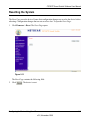
Main Screen > Switch Setting > Exit
1. Click Exit from the Switch Setting chapter to close the Smartwizard Discovery program.
3-9
Smartwizard Discovery Program
v2.0, November 2006
FS728TP Smart Switch Software User Manual
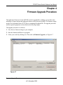
Chapter 4
Firmware Upgrade Procedure
The application Firmware for the FS728TP switch is upgradeable, enabling your switch to take
advantage of improvements and additional features as they become available. The firmware image
needs to be downloaded from a TFTP Server containing the updated file. The upgrade procedure
and the required equipment are described in the following chapter.
The upgrade procedure is as follows:
1. Save the new firmware image to your computer.
2. Start the Smartwizard Discovery program.
3. Select your switch by clicking on it. Then click on Firmware Upgrade, see Figure 4-7.
Figure 4-7
Firmware Upgrade Procedure
4-1
v0.0, November 2006
Reference Manual for the FS728TP Smart Switch
Figure 4-8
4. Enter the location of the new firmware image in the Firmware path below Firmware setting.
Alternatively, you can click Browse to locate the file. Enter following path, tftp://{tftp
address}/{file name}.
5. Enter Password, click Apply and click Start Upgrade to download the new firmware file in
non-volatile memory. The system software is automatically loaded to all stacking members.
4-2
Firmware Upgrade Procedure
v0.0, November 2006
FS728TP Smart Switch Software User Manual
Figure 4-9
Once the system finishes the firmware upgrade process, the switch automatically reboots.
Smartwizard Discovery determines the success of the upgrade process based on the success of the
system reboot.
Firmware Upgrade Procedure
4-3
v0.0, November 2006
FS728TP Smart Switch Software User Manual
Chapter 5
Configuring the Device Using Your Browser
This chapter contains information for configuring the device using your web browser and includes
the following topics:
•
Getting Started
•
Resetting the System
•
Defining Device Information
•
Configuring Device Security
•
Defining RADIUS Settings
•
Defining TACACS+ Authentication
•
Configuring Power over Ethernet
•
Configuring Interfaces
•
Configuring VLANs
•
Defining the Forwarding Address Tables
•
Configuring the Spanning Tree Protocol
•
Configuring Multicast Forwarding
•
Managing System Files
•
Configuring Quality of Service
•
Configuring SNMP Security
•
Monitoring the Device
•
Managing RMON Statistics
•
Resetting to Factory Default Values
5-1
Configuring the Device Using Your Browser
v2.0, November 2006
FS728TP Smart Switch Software User Manual
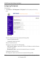
Getting Started
This section describes setting browser interface options, and using the FS728TP switch’s home
page. This section includes the following sections:
•
Opening the NETGEAR FS728TP Web Interface
•
Understanding the Web Interface
•
Using the NETGEAR Web Management System Buttons
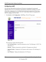
Opening the NETGEAR FS728TP Web Interface
The NETGEAR FS728TP switch web interface can be accessed from any PC with a web browser.
To start the NETGEAR application:
1. Open a web browser.
2. Enter the device IP address in the address bar.
3. Press Enter. The Logon Page appears.
Figure 5-10
4. Enter “password” in the Password field.
5. Click
. The NETGEAR FS728TP web interface displays.
Configuring the Device Using Your Browser
v2.0, November 2006
5-2
FS728TP Smart Switch Software User Manual
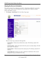
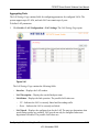
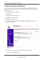
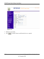
Understanding the Web Interface
The NETGEAR FS728TP web interface contains the following views:
•
Navigation Pane – Located on the left side of the NETGEAR FS728TP web interface. The
Navigation Pane provides an expandable Navigation Pane of the features and their component.
The Navigation Pane is marked as 1 in Navigation Pane.
•
Device View – Located on the right side of the NETGEAR FS728TP web interface. The
Device View provides a view of the device, an information or table area, and of configuration
instructions. The Device View is marked as 2 in Navigation Pane.
•
Information Buttons – Located in the upper right corner of the NETGEAR FS728TP web
interface, the information buttons provide connections to NETGEAR support and the online
manual. See item 3 in Navigation Pane.
Figure 5-11
Navigation Pane
The Navigation Pane contains a list of the different features that can be configured including
switching features, ports, spanning tree, VLANs, class of service, port aggregation, multicast
support, and statistics. The Navigation Pane branches can be expanded to view all the components
under a specific feature or retracted to hide the feature's components.
5-3
Configuring the Device Using Your Browser
v2.0, November 2006
FS728TP Smart Switch Software User Manual
Device View
The following section describes the different aspects of the Device View. The device provides
information about FS728TP, the different components, and the Work Desk. The Work Desk in the
Device View provides a work area that contains device tables, general device information, and
configurable device parameters.
Using The NETGEAR Web Management System Buttons
This section contains information about the different NETGEAR FS728TP browser interface
buttons. The FS728TP web browser provides the following buttons:
•
Information Buttons – Provide access to informational services including technical support,
online help, device information, and closing the NETGEAR browser.
•
Device Management Buttons – Provide an explanation of the management buttons in the
NETGEAR FS728TP Switch, including the Add, Delete, Query, and Apply Changes buttons.
Information Buttons
The NETGEAR FS728TP Switch web browser contains the following information buttons:
Table 5-1. Information Buttons
Button
Description
Opens the NETGEAR support page. The NETGEAR technical support page
URL is http://kbserver.netgear.com/.
Opens the Online Help.
Help Button
The Online Help contains information to assist in configuring and managing the switch. Help
topics can be located using the Help Search, referenced by Index entry, or referenced by Help topic
in the Help Navigation Pane.
To access the Online Help:
•
Select a Help topic. The selected Help topic page opens:
Or
•
Click
. The Online Help opens, as shown in Online Help Main Page.
Configuring the Device Using Your Browser
v2.0, November 2006
5-4
FS728TP Smart Switch Software User Manual
Figure 5-12
Device Management Buttons
The NETGEAR FS728TP Switch web browser GUI management buttons allow network managers
to easily configure the device from remote locations. The NETGEAR FS728TP Switch web
browser GUI contains the following management buttons:
Table 5-2. Device Management Buttons
Button
Description
Applies set changes to the device.
Adds information to tables or information windows.
Refreshes device information.
Resets statistics counters.
Performs copper cables test.
Restores the factory defaults.
5-5
Configuring the Device Using Your Browser
v2.0, November 2006
FS728TP Smart Switch Software User Manual
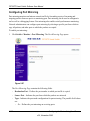
Resetting the System
The Reset Page resets the device. Ensure that configuration changes are saved to the device before
rebooting. Configuration changes that are not saved are lost. To open the Reset Page:
1. Click Firmware > Reset. The Reset Page opens:
Figure 5-13
The Reset Page contains the following field:
2. Click
. The device is reset.
Configuring the Device Using Your Browser
v2.0, November 2006
5-6
FS728TP Smart Switch Software User Manual
Defining Device Information
This section contains the following topics:
•
Viewing the Device Zoom View
•
Viewing the Device Information
•
Configuring System Time
5-7
Configuring the Device Using Your Browser
v2.0, November 2006
FS728TP Smart Switch Software User Manual
Viewing the Device Zoom View
The Zoom Page provides a graphic representation of the device, including the port and LED
statuses.
1. Click System > Zoom. The Zoom Page opens:
Figure 5-14
Configuring the Device Using Your Browser
v2.0, November 2006
5-8
FS728TP Smart Switch Software User Manual
Viewing the Device Information
The contains parameters for configuring general device information, including the system name,
location, contact, System Object ID, System Up Time and Base MAC Addresses, and both
software and hardware versions.
1. Click System > Switch Status. The Switch Status Page opens:
Figure 5-15
The Switch Status Page contains the following fields:
5-9
–
System Name – Defines the user-defined device name. The field may contain 0-160
characters.
–
System Location – Defines the location where the system is currently running. The field
may contain 0-160 characters.
–
System Contact – Defines the name of the contact person. The field may contain 0-160
characters.
–
System Object ID – Displays the vendor’s authoritative identification of the network
management subsystem contained in the entity.
Configuring the Device Using Your Browser
v2.0, November 2006
FS728TP Smart Switch Software User Manual
–
Date – Displays the current date.
–
Local Time – Displays the Local time.
–
System Up Time – Displays the amount of time since the most recent device reset. The
system time is displayed in the following format: Days, Hours, Minutes, and Seconds. For
example, 41 days, 2 hours, 22 minutes and 15 seconds.
–
Idle Timeout (Min) – Indicates the amount of time (minutes) that elapses before an idle
station is timed out. Idle stations that are timed out must login to the system. The field
range is 5 - 30 minutes. The field default value is 5 minutes.
–
Base MAC Address – Displays the MAC address.
–
Serial Number – Displays the device serial number.
–
Model Number – Displays the device model number and name.
–
Hardware Version – Displays the installed device hardware version number.
–
Boot Version – Displays the current boot version running on the device.
–
Software Version – Displays the installed software version number.
2. Define the fields.
3. Click
.
Configuring System Time
The Time Page contains fields for defining system time parameters for both the local hardware
clock and the external SNTP clock. If the system time is kept using an external SNTP clock, and
the external SNTP clock fails, the system time reverts to the local hardware clock.
1. Click Switch > Time. The Time Page opens:
Configuring the Device Using Your Browser
v2.0, November 2006
5-10
FS728TP Smart Switch Software User Manual
Figure 5-16
The Time Page contains the following fields:
–
Clock Source – Indicates the source used to set the system clock. The possible field
values are:
–
Local Settings – Indicates that the system time is set locally.
–
SNTP – Indicates that the system time is set via an SNTP server.
–
Date – Displays system date. The field format is Day/Month/Year. For example: 04/May/
50 (May 4, 2050).
–
Local Time – Displays system time. The field format is HH:MM:SS. For example:
21:15:03.
–
Time Zone Offset – Indicates the difference between Greenwich Mean Time (GMT) and
local time. For example, the Time Zone Offset for Paris is GMT +1, while the Time Zone
Offset for New York is GMT –5.
5-11
Configuring the Device Using Your Browser
v2.0, November 2006
FS728TP Smart Switch Software User Manual
–
SNTP Server 1 – Defines the primary SNTP server IP address. The Primary SNTP server
is the first server used to retrieve the system time. The following option is available:
–
–
Delete – Removes the currently configured SNTP server.
SNTP Server 2 – Defines the secondary SNTP server IP address. The Secondary SNTP
server is retrieves the system time if the Primary SNTP server times out. The following
option is available:
–
Delete – Removes the currently configured SNTP server.
2. Define the relevant fields.
3. Click
. The Time parameters are defined.
Configuring the Device Using Your Browser
v2.0, November 2006
5-12
FS728TP Smart Switch Software User Manual
Configuring Device Security
This section contains information for managing both storm control and port security and includes
the following topics:
•
Defining Port Authentication Properties
•
Viewing EAP Statistics
•
Enabling Storm Control
•
ACL Overview
•
Defining MAC Based Access Control Lists
•
Configuring Passwords
•
Defining RADIUS Settings
•
Defining TACACS+ Authentication
5-13
Configuring the Device Using Your Browser
v2.0, November 2006
FS728TP Smart Switch Software User Manual
Defining Port Authentication Properties
The Port Authentication Properties Page allows network managers to configure network
authentication parameters. In addition, Guest VLANs are enabled from the Properties Page. To
define the port authentication properties:
1. Click Switch > Security > Port Authentication > Properties. The Port Authentication
Properties Page opens:
Figure 5-17
The Port Authentication Properties Page contains the following fields:
–
–
Port Based Authentication State – Indicates if Port Authentication is enabled on the
device. The possible field values are:
–
Enable – Enables port-based authentication on the device.
–
Disable – Disables port-based authentication on the device.
Authentication Method – Specifies the authentication method used for port
authentication. The possible field values are:
–
None – Indicates that no authentication method is used to authenticate the port.
–
RADIUS – Provides port authentication using the RADIUS server.
Configuring the Device Using Your Browser
v2.0, November 2006
5-14
FS728TP Smart Switch Software User Manual
–
–
–
RADIUS, None – Provides port authentication, first using the RADIUS server. If the
port is not authenticated, then no authentication method is used, and the session is
permitted.
Guest VLAN Status – Specifies whether the Guest VLAN is enabled on the device. The
possible field values are:
–
Enable – Enables using a Guest VLAN for unauthorized ports. If a Guest VLAN is
enabled, the unauthorized port automatically joins the VLAN selected in the VLAN
List field.
–
Disable – Disables port-based authentication on the device. This is the default.
VLAN List – Contains a list of VLANs. The Guest VLAN is selected from the VLAN list.
2. Define the fields.
3. Click
5-15
. The network authentication properties are set and the device is updated.
Configuring the Device Using Your Browser
v2.0, November 2006
FS728TP Smart Switch Software User Manual
Defining Port Authentication
The Port Authentication Page allows network managers to configure port-based authentication
global parameters. To define the port-based authentication global properties:
1. Click Switch > Security > Port Authentication > Port Authentication. The Port
Authentication Page opens:
Figure 5-18
The Port Authentication Page contains the following fields:
–
ID – Displays a list of interfaces on which port-based authentication is enabled.
–
User Name – Displays the supplicant user name.
–
Admin Port Control – Displays the admin port authorization state.
–
ForceUnauthorized – Indicates that either the port control is force Unauthorized and
the port link is down, or the port control is Auto but a client has not been authenticated
via the port.
–
ForceAuthorized – Indicates that the port control is Forced Authorized, and clients
have full port access.
Configuring the Device Using Your Browser
v2.0, November 2006
5-16
FS728TP Smart Switch Software User Manual
–
Auto – Indicates that the port control is Auto and a single client has been authenticated
via the port.
–
Current Port Control – Displays the current port authorization state.
–
Guest VLAN – Specifies whether the Guest VLAN is enabled on the device. The possible
field values are:
–
–
Enable – Enables using a Guest VLAN for unauthorized ports. If a Guest VLAN is
enabled, the unauthorized port automatically joins the VLAN selected in the VLAN
List field.
–
Disable – Disables port-based authentication on the device. This is the default.
Enable Periodic Reauthentication – Permits immediate port reauthentication. The
possible field values are:
–
Enable – Enables immediate port reauthentication. This is the default value.
–
Disable – Disables port reauthentication.
–
Reauthentication Period – Displays the time span (in seconds) in which the selected port
is reauthenticated. The field default is 3600 seconds.
–
Authenticator State – Displays the current authenticator state.
–
Quiet Period – Displays the number of seconds that the device remains in the quiet state
following a failed authentication exchanges. The possible field range is 0-65535. The field
default is 60 seconds.
–
Resending EAP – Defines the amount of time (in seconds) that lapses before EAP
requests are resent. The field default is 30 seconds.
–
Max EAP Requests – Displays the total amount of EAP requests sent. If a response is not
received after the defined period, the authentication process is restarted. The field default
is 2 retries.
–
Supplicant Timeout – Displays the amount of time (in seconds) that lapses before EAP
requests are resent to the supplicant. The field default is 30 seconds.
–
Server Timeout – Displays the amount of time (in seconds) that lapses before the device
re-sends a request to the authentication server. The field default is 30 seconds.
–
Termination Cause – Indicates the reason for which the port authentication was
terminated.
5-17
Configuring the Device Using Your Browser
v2.0, November 2006
FS728TP Smart Switch Software User Manual
2. Click an ID. The Modify Port Authentication Page opens:
Figure 5-19
3. Edit the fields.
4. Click
. The port authentication settings are defined and the device is updated.
Configuring the Device Using Your Browser
v2.0, November 2006
5-18
FS728TP Smart Switch Software User Manual
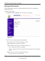
Viewing EAP Statistics
The EAP Statistics Page contains information about EAP packets received on a specific port. To
view the EAP Statistics:
1. Click Switch > Security > Port Authentication > EAP Statistics. The EAP Statistics Page
opens:
Figure 5-20
The EAP Statistics Page contains the following fields:
–
Port – Indicates the port, which is polled for statistics.
–
Refresh Rate – Indicates the amount of time that passes before the EAP statistics are
refreshed. The possible field values are:
–
5-19
–
15 Seconds – Indicates that the EAP statistics are refreshed every 15 seconds.
–
30 Seconds – Indicates that the EAP statistics are refreshed every 30 seconds.
–
60 Seconds – Indicates that the EAP statistics are refreshed every 60 seconds.
–
No Refresh – Indicates that the EAP statistics are not refreshed.
Frames Receive – Indicates the number of valid EAPOL frames received on the port.
Configuring the Device Using Your Browser
v2.0, November 2006
FS728TP Smart Switch Software User Manual
–
Frames Transmit – Indicates the number of EAPOL frames transmitted via the port.
–
Start Frames Receive – Indicates the number of EAPOL Start frames received on the
port.
–
Log off Frames Receive – Indicates the number of EAPOL Logoff frames that have been
received on the port.
–
Respond ID Frames Receive – Indicates the number of EAP Resp/Id frames that have
been received on the port.
–
Respond Frames Receive – Indicates the number of valid EAP Response frames received
on the port.
–
Request ID Frames Transmit – Indicates the number of EAP Req/Id frames transmitted
via the port.
–
Request Frames Transmit – Indicates the number of EAP Request frames transmitted
via the port.
–
Invalid Frames Receive – Indicates the number of unrecognized EAPOL frames that
have been received by on this port.
–
Length Error Frames Receive – Indicates the number of EAPOL frames with an invalid
Packet Body Length received on this port.
–
Last Frame Version – Indicates the protocol version number attached to the most
recently received EAPOL frame.
–
Last Frame Source – Indicates the source MAC address attached to the most recently
received EAPOL frame.
Configuring the Device Using Your Browser
v2.0, November 2006
5-20
FS728TP Smart Switch Software User Manual
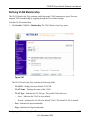
Enabling Storm Control
Storm control limits the amount of Multicast and Broadcast frames accepted and forwarded by the
device. When Layer 2 frames are forwarded, Broadcast, and Multicast frames are flooded to all
ports on the relevant VLAN. This occupies bandwidth and loads all nodes on all ports.
A Broadcast Storm is a result of an excessive amount of broadcast messages simultaneously
transmitted across a network by a single port. Forwarded message responses are heaped onto the
network, straining network resources or causing the network to time out.
Storm control is enabled for all ports by defining the packet type and the rate the packets are
transmitted. The system measures the incoming Broadcast and Multicast frame rates separately on
each port, and discards the frames when the rate exceeds a user-defined rate. By default, storm
control is enabled on all ports - broadcast only - with threshold of 200 kbps. Storm Control is
enabled by default.
5-21
Configuring the Device Using Your Browser
v2.0, November 2006
FS728TP Smart Switch Software User Manual
The Storm Control Page provides fields for configuring broadcast storm control.
To enable storm control:
1. Click Switch > Security > Traffic > Storm Control. The Storm Control Page opens:
Figure 5-21
The Storm Control Page contains the following fields:
–
Interface – Displays the port number for which the storm control information is
displayed.
–
Broadcast Control – Indicates if forwarding Broadcast packet types is enabled on the
interface for which the storm control information is displayed. The possible field values
are:
–
–
Enable – Enables storm control on all broadcast only ports with threshold of 200 kbps.
Enabled is the default.
–
Disable – Disables storm control on the interface.
Broadcast Mode – Specifies the Broadcast mode currently enabled on the device. The
possible field values are:
Configuring the Device Using Your Browser
v2.0, November 2006
5-22
FS728TP Smart Switch Software User Manual
–
–
Unknown Unicast, Multicast & Broadcast – Counts Unicast, Multicast, and Broadcast
traffic.
–
Multicast & Broadcast – Counts Broadcast and Multicast traffic together.
–
Broadcast Only – Counts only Broadcast traffic.
Broadcast Rate Threshold – Indicates the maximum rate (kilobits per second) at which
unknown packets are forwarded. The range is 3500-250,000 kbps. The default value is
200 kbps.
2. Click an interface. The Storm Control Modify Page opens:
Figure 5-22
3. Modify the fields.
4. Click
5-23
. Storm control is enabled on the device.
Configuring the Device Using Your Browser
v2.0, November 2006
FS728TP Smart Switch Software User Manual
ACL Overview
Access Control Lists (ACL) allow network managers to define classification actions and rules for
specific ingress ports. Packets entering an ingress port, with an active ACL, are either admitted or
denied entry and the ingress port is disabled. If they are denied entry, the user can disable the port.
To implement ACLs, first define the ACL to specify what actions should be taken when packets
are received and then specify which ports should follow these actions by binding the ACL to them.
Defining MAC Based Access Control Lists
Access Control Lists consist of a list of Access Control Elements. An Access Control element
specifies an action to apply when a packet is received from a specific MAC address or range of
MAC addresses.
The Define ACLs Page allows a MAC- based ACL to be defined. ACEs can be added only if the
ACL is not bound to an interface.
To define MAC Based ACLs:
1. Click Switch > Security > Access Control > Define MAC ACL. The Define ACLs Page
opens:
Configuring the Device Using Your Browser
v2.0, November 2006
5-24
FS728TP Smart Switch Software User Manual
Figure 5-23
The Define ACLs Page contains the following fields:
–
ACL Name – Displays the user-defined MAC based ACLs.
–
Remove ACL – Removes the ACLs. The possible field values are:
–
Checked – Removes the selected MAC based ACL.
–
Unchecked – Maintains the MAC based ACLs.
–
ID – Matches the packet’s VLAN ID to the ACE. The possible field values are 1 to 4095.
–
Priority – Indicates the ACE priority, which determines which ACE is matched to a
packet on a first-match basis. The possible field values are 1-2147483647.
–
Source Address
–
5-25
MAC Address – Matches the source MAC address to which packets are addressed to
the ACE.
Configuring the Device Using Your Browser
v2.0, November 2006
FS728TP Smart Switch Software User Manual
–
–
Mask – Indicates the source MAC Address wild card mask. Wildcards are used to
mask all or part of a source IP Address. Wild card masks specify which bits are used
and which bits are ignored. A wild card mask of ff: ff:ff:ff:ff:ff indicates that no bit is
important. A wildcard of 00.00.00.00.00.00 indicates that all the bits in the address to
which the mask is applied are important. For example, if the source IPv6 address is
14.36.18.19.1.1 and the wildcard mask is 255.36.184.00.00.00, the middle two bits of
the IP address are used, while the last three fields are ignored.
Destination Address
–
MAC Address – Matches the destination MAC address to which packets are addressed
to the ACE.
–
Mask – Indicates the destination MAC Address wild card mask. Wildcards are used to
mask all or part of a destination IP Address. Wild card masks specify which bits are
used and which bits are ignored. A wild card mask of ff: ff:ff:ff:ff:ff indicates that no
bit is important. A wildcard of 00.00.00.00.00.00 indicates that all the bits are
important. For example, if the source IP address 14.36.18.19.1.1 and the wildcard
mask is 255.36.184.00.00.00, the middle two bits of the IP address are used, while the
last three bits are ignored.
–
VLAN ID – Matches the packet’s VLAN ID to the ACE. The possible field values are 1 to
4095.
–
Action – Indicates the ACL forwarding action. Possible field values are:
–
–
Permit – Forwards packets which meet the ACL criteria.
–
Deny – Drops packets which meet the ACL criteria.
–
Shutdown – Drops packet that meet the ACL criteria, and disables the port to which
the packet was addressed.
Delete – Deletes the rule from the ACL. The possible field values are:
–
Checked – Deletes the rule from the ACL.
–
Unchecked – Does not delete the rule from the ACL.
Configuring the Device Using Your Browser
v2.0, November 2006
5-26
FS728TP Smart Switch Software User Manual
2. Click
. The Add MAC Based ACL Page opens:
Figure 5-24
The Add MAC Based ACL Page contains the additional fields:
3. Define the relevant fields.
4. Click
5-27
. The MAC based ACL is defined, and the device is updated.
Configuring the Device Using Your Browser
v2.0, November 2006
FS728TP Smart Switch Software User Manual
Defining Access Control Lists Binding
To define ACL Binding:
1. Click Switch > Security > Access Control > ACL Binding. The ACL Binding Page opens:
Figure 5-25
The ACL Binding Page contains the following fields:
–
Ports – Indicates that ports are displayed.
–
LAGs – Indicates that LAGs are being displayed.
–
Interface – Displays the VLAN for which the ACL parameters are defined.
–
ACL Name – Contains a list of the MAC based ACLs.
Configuring the Device Using Your Browser
v2.0, November 2006
5-28
FS728TP Smart Switch Software User Manual
2. Click on an Interface No. to define ACL Binding. The ACL Binding Page opens:
Figure 5-26
The ACL Binding Page contains the following fields:
–
ACL Name – Contains a list of the MAC based ACLs, which is bound to the interface
–
Port – Indicates the port for which the ports are displayed.
3. Select the ACL Name and ports to be bound.
4. Click
5-29
. The ACL Binding is defined, and the device is updated.
Configuring the Device Using Your Browser
v2.0, November 2006
FS728TP Smart Switch Software User Manual
Port Based Security
Network security can be increased by limiting access on a specific port only to users with specific
MAC addresses. The MAC addresses can be dynamically learned or statically configured. Locked
port security monitors both received and learned packets that are received on specific ports.
Access to the locked port is limited to users with specific MAC addresses. These addresses are
either manually defined on the port, or learned on that port up to the point when it is locked. When
a packet is received on a locked port and the packet source MAC address is not tied to that port
(either it was learned on a different port, or it is unknown to the system), the protection mechanism
is invoked. It provides the following options for unauthorized packets arriving at a locked port:
•
Forwarded
•
Discarded with no trap
•
Discarded with a trap
•
Shuts down the port
Locked port security also enables storing a list of MAC addresses in the configuration file. The
MAC address list can be restored after the device has been reset. Disabled ports are activated from
the Port Security Page.
Configuring the Device Using Your Browser
v2.0, November 2006
5-30
FS728TP Smart Switch Software User Manual
To define port security:
1. Click Switch > Security > Traffic > Port Security. The Port Security Page opens:
Figure 5-27
The Port Security Page contains the following fields:
–
Interface – Displays the port or LAG name.
–
Interface Status – Indicates the host status.
–
Learning Mode – Defines the locked port type. The Learning Mode field is enabled only
if Locked is selected in the Set Port field. The possible field values are:
5-31
–
Classic Lock – Locks the port, and only forwards packets that have been learned
statically or dynamically, prior to locking the port. The lock is effective immediately.
–
Limited Dynamic Lock – Indicates the port is unlocked. Locks the port after a userdefined number of MAC addresses have been dynamically learned on the port. After
the port is locked, packets are forwarded only from MAC addressees that have been
learned prior to locking the port.
Configuring the Device Using Your Browser
v2.0, November 2006
FS728TP Smart Switch Software User Manual
–
Max Entries – Specifies the number of MAC address that can be learned on the port. The
Max Entries field is enabled only if Locked is selected in the Set Port field. In addition, the
Limited Dynamic Lock mode is selected. The default is 1.
–
Action – Indicates the action to be applied to packets arriving on a locked port. The
possible field values are:
–
–
–
Forward – Forwards packets from an unknown source without learning the MAC
address.
–
Discard – Discards packets from any unlearned source. This is the default value.
–
Shutdown – Discards packets from any unlearned source and shuts down the port. The
port remains shut down until reactivated or until the device is reset.
Trap – Enables traps when a packet is received on a locked port. The possible field values
are:
–
Checked – Enables traps.
–
Unchecked – Disables traps. This is the default value.
Trap Frequency (Sec) – Indicates the frequency at which traps are sent. The field format
is in seconds. The default value is 10 seconds.
Configuring the Device Using Your Browser
v2.0, November 2006
5-32
FS728TP Smart Switch Software User Manual
4. Select and click an Interface.
Figure 5-28
5. Modify the fields.
6. Click
5-33
. The port security settings are defined and the device is updated.
Configuring the Device Using Your Browser
v2.0, November 2006
FS728TP Smart Switch Software User Manual
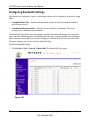
Configuring Passwords
The Password Setting Page contains parameters for configuring device passwords. Authentication
on this device uses only a password, not a user name. Therefore, in order to configure RADIUS/
TACACS+ authentication, the user name should be configured as $enab15$ on the RADIUS/
TACACS+ server.
To define device passwords:
1. Click System > Management Security > Password. The Password Setting Page opens:
Figure 5-29
The Password Setting Page contains the following fields:
–
Authentication Type – Displays authentication type used. The order by which
authentication is performed, If the first authentication method is not available, the second
one is used, until the full list is exhausted. For example, if "RADIUS, TACACS+, None"
list is selected, the RADIUS server is used to authenticate a user. If the RADIUS server is
unavailable, or there is no RADIUS server on the network, the TACACS+ server is used to
authenticate a user. If the TACACS+ server is unavailable, or there is no TACACS+ server
on the network, then the user logs in with no authentication. The possible field values are:
–
Local – Authentication occurs locally.
Configuring the Device Using Your Browser
v2.0, November 2006
5-34
FS728TP Smart Switch Software User Manual
–
RADIUS – Authentication occurs at the RADIUS server.
–
TACACS+ – Authentication occurs at the TACACS+ server.
–
None – No authentication type is applied.
–
Old Password – Indicates the current password used to access the system.
–
New Password – Defines a new password for accessing the system.
–
Re-type New Word – Verifies the new password used to access the system.
2. Define the fields.
3. Click
5-35
. The password is defined and the device is updated.
Configuring the Device Using Your Browser
v2.0, November 2006
FS728TP Smart Switch Software User Manual
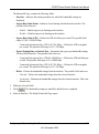
Defining RADIUS Settings
Remote Authorization Dial-In User Service (RADIUS) servers provide additional security for
networks. RADIUS servers provide a centralized authentication method for web access.
The default parameters are user-defined, and are applied to newly defined RADIUS servers. If new
default parameters are not defined, the system default values are applied to newly defined
RADIUS servers.
To configure RADIUS servers:
1. Click System > Management Security > RADIUS. The RADIUS Page opens:
Figure 5-30
The RADIUS Page contains the following fields:
–
Primary Server – Defines the RADIUS Primary Server authentication fields.
–
Backup Server – Defines the RADIUS Backup Server authentication fields.
–
Host IP Address – Defines the RADIUS Server IP address.
Configuring the Device Using Your Browser
v2.0, November 2006
5-36
FS728TP Smart Switch Software User Manual
–
Authentication Port – Identifies the authentication port. The authentication port is used
to verify the RADIUS server authentication. The authenticated port default is 1812.
–
Number of Retries – Defines the number of transmitted requests sent to the RADIUS
server before a failure occurs. Possible field values are 1-10. The default value is 3.
–
Timeout for Reply – Defines the amount of time (in seconds) the device waits for an
answer from the RADIUS server before retrying the query, or switching to the next server.
Possible field values are 1-30. The default value is 3.
–
Dead Time – Defines the default amount of time (in minutes) that a RADIUS server is
bypassed for service requests. The range is 0-2000. The default value is 0.
–
Key String – Defines the default key string used for authenticating and encrypting all
RADIUS-communications between the device and the RADIUS server. This key must
match the RADIUS encryption.
–
Usage Type – Specifies the RADIUS server authentication type. The default value is Log
in. The possible field values are:
–
Log in – Indicates the RADIUS server is used for authenticating user name and
passwords.
–
802.1X – Indicates the RADIUS server is used for 802.1X authentication.
–
All – Indicates the RADIUS server is used for authenticating user names and
passwords, and 802.11X port authentication.
2. Define the fields.
3. Click
5-37
. The RADIUS Servers are enabled, and the system is updated.
Configuring the Device Using Your Browser
v2.0, November 2006
FS728TP Smart Switch Software User Manual
Defining TACACS+ Authentication
Terminal Access Controller Access Control System (TACACS+) provides centralized security user
access validation. The system supports up-to 4 TACACS+ servers.
TACACS+ provides a centralized user management system, while still retaining consistency with
RADIUS and other authentication processes. TACACS+ provides the following services:
•
Authentication – Provides authentication during login and via user names and user-defined
passwords.
•
Authorization – Performed at login. Once the authentication session is completed, an
authorization session starts using the authenticated user name.
The TACACS+ protocol ensures network integrity through encrypted protocol exchanges between
the client and TACACS+ server.
The TACACS+ default parameters are user-assigned defaults. The default settings are applied to
newly defined TACACS+ servers. If default values are not defined, the system defaults are applied
to the new TACACS+ new servers.
Configuring the Device Using Your Browser
v2.0, November 2006
5-38
FS728TP Smart Switch Software User Manual
To define TACACS+ Settings:
1. Click System > Management Security > TACACS+. The TACACS+ Page opens:
Figure 5-31
The TACACS+ Page contains the following fields:
–
Primary Server – Defines the RADIUS Primary Server authentication fields.
–
Backup Server – Defines the RADIUS Backup Server authentication fields.
–
Host IP Address – Defines the TACACS+ Server IP address.
–
Key String – Defines the default authentication and encryption key for TACACS+
communication between the device and the TACACS+ server.
–
Authentication Port (0-65535) – Defines the port number via which the TACACS+
session occurs. The default port is port 49.
–
Timeout for Reply – Defines the default time that passes before the connection between
the device and the TACACS+ times out.
–
Single Connection – Maintains a single open connection between the device and the
TACACS+ server. The possible field values are:
–
5-39
Checked – Enables a single connection.
Configuring the Device Using Your Browser
v2.0, November 2006
FS728TP Smart Switch Software User Manual
–
Unchecked – Disables a single connection.
2. Define the fields.
3. Click
. The TACACS+ Server is enabled, and the device is updated.
Configuring the Device Using Your Browser
v2.0, November 2006
5-40
FS728TP Smart Switch Software User Manual
Viewing System Logs
Event messages have a unique format, as per the SYSLOG RFC recommended message format for
all error reporting, for example, Syslog+ local device reporting. Messages are assigned a severity
code, and include a message mnemonic, which identifies the source application generating the
message. Messages are filtered based on their urgency or relevancy. The following table contains
the Log Severity Levels:
Table 6:
Severity Levels
Severity
Severity Level
Severity Level
Emergency
0
Indicates that the system is not functioning.
Alert
1
Indicates that the system needs immediate
attention.
Critical
2
Indicates that the system is in a critical state.
Error
3
Indicates that a system error has occurred.
Warning
4
indicates that a system warning is logged.
Notice
5
Indicates that the system is functioning properly,
but system notice is logged.
Informational
6
Provides device information.
Debug
7
Provides detailed log information.
This section provides information for managing logs. The logs enable viewing device events in
real time, and recording the events for later usage. Logs record and manage events and report
errors and informational messages.
This section includes the following topics:
•
Logs Configuration
•
Viewing the Memory Logs
•
Viewing the Flash Logs
•
Viewing Server Logs
5-41
Configuring the Device Using Your Browser
v2.0, November 2006
FS728TP Smart Switch Software User Manual
Logs Configuration
The Log Configuration Page contains fields for defining which events are recorded to which logs.
It contains fields for enabling logs globally, and parameters for defining logs. Log messages are
listed from the highest severity to the lowest severity level. When a severity level is selected, all
severity level choices above the selection are selected automatically.
To enable event logging:
1. Click System > Logs > Logs Configuration. The Log Configuration Page opens:
Figure 5-32
The Log Configuration Page contains the following fields:
–
–
Enable Logging – Indicates if device global logs for Cache, File, and Server Logs are
enabled. Console logs are enabled by default. The possible field values are:
–
Checked – Enables device logs.
–
Unchecked – Disables device logs.
Severity – Indicates the log severity and urgency level. The following are the available log
severity levels:
Configuring the Device Using Your Browser
v2.0, November 2006
5-42
FS728TP Smart Switch Software User Manual
–
Emergency – The highest warning level. If the device is down or not functioning
properly, an emergency log message is saved to the specified logging location.
–
Alert – The second highest warning level. An alert log is saved, if there is a serious
device malfunction; for example, all device features are down.
–
Critical – The third highest warning level. A critical log is saved if a critical device
malfunction occurs; for example, two device ports are not functioning, while the rest
of the device ports remain functional.
–
Error – A device error has occurred; for example, if a single port is offline.
–
Warning – The lowest level of a device warning. The device is functioning, but an
operational problem has occurred.
–
Notice – Provides device information.
–
Informational – Provides device information.
–
Debug – Provides debugging messages.
–
RAM Logs – Defines the minimum severity level from which logs are sent to the RAM
Log kept in RAM (Cache).
–
Log File – Defines the minimum severity level from which logs are sent to the log file
kept in FLASH memory.
2. Define the Enable Logging and Severity fields.
3. Click
5-43
. The log parameters are set and the device is updated.
Configuring the Device Using Your Browser
v2.0, November 2006
FS728TP Smart Switch Software User Manual
Viewing the Memory Logs
The Memory Logs Page contains all system logs in a chronological order that are saved in RAM
(Cache).
To open the Memory Logs Page:
1. Click System > Logs > Memory Logs. The Memory Logs Page opens:
Figure 5-33
The Memory Logs Page contains the following fields:
–
ID – Displays the log entry in the Memory Log table.
–
Log Index – Displays the log number.
–
Log Time – Displays the time at which the log was generated.
–
Severity – Displays the log severity.
–
Description – Displays the log message text.
2. Click
. The Memory Logs are cleared, and the device is updated.
Configuring the Device Using Your Browser
v2.0, November 2006
5-44
FS728TP Smart Switch Software User Manual
Viewing the Flash Logs
The Flash Logs Page contains information about log entries saved to the log file in Flash,
including the time the log was generated, the log severity, and a description of the log message.
The message log is available after reboot.
To view the message logs:
1. Click System > Logs > Flash Logs. The Flash Logs Page opens:
Figure 5-34
The Flash Logs Page contains the following fields:
–
ID – Displays the log entry in the Flash Logs table.
–
Log Index – Displays the log number.
–
Log Time – Displays the time at which the log was generated.
–
Severity – Displays the log severity.
–
Description – Displays the log message text.
2. Click
5-45
. The Memory Logs are cleared, and the device is updated.
Configuring the Device Using Your Browser
v2.0, November 2006
FS728TP Smart Switch Software User Manual
Viewing Server Logs
The Server Logs Page contains information for viewing and configuring the remote log servers.
New log servers can be defined and the log severity sent to each server.
To open the Server Logs Page:
1. Click System > Logs > Server Logs. The Server Logs Page opens:
Figure 5-35
The Server Logs Page contains the following fields:
–
ID – Displays the log entry in the Server Logs table.
–
Server – Specifies the server’s IP address to which logs can be sent.
–
UDP Port – Defines the UDP port to which the server logs are sent. The possible range is
1 - 65535. The default value is 514.
–
Facility – Defines an application from which system logs are sent to the remote server.
Only one facility can be assigned to a single server. If a second facility level is assigned,
the first facility is overridden. All applications defined for a device utilize the same facility
on a server. The field default is Local 7. The possible field values are Local 0 - Local 7.
–
Description – Displays the user-defined server description.
Configuring the Device Using Your Browser
v2.0, November 2006
5-46
FS728TP Smart Switch Software User Manual
–
Minimum Severity – Indicates the minimum severity from which logs are sent to the
server. For example, if Notice is selected, all logs with a severity level of Notice and
higher are sent to the remote server. The default value is Informational.
–
Delete – Deletes the currently selected servers from the Servers list. The possible field
values are:
–
Checked – Removes the selected server from the Server Logs Page. Once removed,
logs are no longer sent to the removed server.
–
Unchecked – Maintains the remote servers.
2. Click
. The Add Server Logs Page opens:
Figure 5-36
3. Define the fields.
4. Click
5-47
. The log is defined and the device is updated.
Configuring the Device Using Your Browser
v2.0, November 2006
FS728TP Smart Switch Software User Manual
Configuring Power over Ethernet
Power over Ethernet (PoE) provides power to devices over existing LAN cabling without updating
or modifying the network infrastructure. This removes the limitation of placing network devices
close to power sources. Power over Ethernet.
•
IP Phones
•
Wireless Access Points
•
IP Gateways
•
Audio and video remote monitoring
Powered Devices are devices that receive power from the source device power supplies, IP phones
are examples of powered devices. Powered devices are connected to the source device via
Ethernet. The PoE Configuration Page contains system PoE information for enabling PoE on the
device, monitoring the current power usage, and enabling PoE traps.
Configuring the Device Using Your Browser
v2.0, November 2006
5-48
FS728TP Smart Switch Software User Manual
To enable PoE on the device:
1. Click System > PoE Configuration. The PoE Configuration Page opens:
Figure 5-37
The PoE Configuration Page contains the following fields:
–
Power Status – Indicates the online power source status. The possible field values are:
–
On – Indicates that the power supply unit is functioning.
–
Off – Indicates that the power supply unit is not functioning.
–
Faulty – Indicates that the power supply unit is functioning, but an error has occurred.
For example, a power overload or a short circuit.
–
Nominal Power – Indicates the actual amount of power the device can supply. The field
value is displayed in Watts.
–
Consumed Power – Indicates the amount of the power used by the device. The field value
is displayed in Watts.
–
System Usage Threshold – Indicates the percentage of power consumed before an alarm
is generated. The field value is 1-99 percent. The default is 95 percent.
–
Traps – Indicate if PoE device traps are enabled. The possible field values are:
5-49
Configuring the Device Using Your Browser
v2.0, November 2006
FS728TP Smart Switch Software User Manual
–
Checked – Enables PoE traps on the device.
–
Unchecked – Disables PoE traps on the device. This is the default value.
–
Interface – Indicates the specific interface for which PoE parameters are defined. PoE
parameters are assigned to the powered device that is connected to the selected interface.
–
Admin Mode – Indicates the device PoE mode. The possible field values are:
–
–
–
Enable – Enables the Device Discovery protocol and provides power to the device
using the PoE module. The Device Discovery Protocol enables the device to discover
Powered Devices attached to the device interfaces and to learn their classification.
This is the default setting.
–
Disable – Disables the Device Discovery protocol and stops the power supply to the
device using the PoE module.
Priority Level – Determines the port priority if the power supply is low. The field default
is low. For example, if the power supply is running at 99% usage, and port 1 is prioritized
as high, but port 3 is prioritized as low, port 1 is prioritized to receive power and port 3
may be denied power. The possible field values are:
–
Low – Defines the PoE priority level as low. This is the default level.
–
Medium – Defines the PoE priority level as Medium.
–
High – Defines the PoE priority level as high. This is the highest PoE priority level.
Class – Indicates the amount of power assigned to the powered device connected to the
selected interface. The powered device classifies devices, and the devices use the
classification information. The field values are:
–
Class 0 – Indicates that the maximum power level at the input of the Powered Device
is 15.4 watts.
–
Class 1 – Indicates that the maximum power level at the input of the Powered Device
is 4.0 watts.
–
Class 2 – Indicates that the maximum power level at the input of the Powered Device
is 7.0 watts.
–
Class 3 – Indicates that the maximum power level at the input of the Powered Device
is 15.4 watts.
–
Class 4 – Treated as Class 0.
–
Output Voltage – Displays the Output Voltage in watts.
–
Output Current (ma) – Displays the Output current in milliamps.
Configuring the Device Using Your Browser
v2.0, November 2006
5-50
FS728TP Smart Switch Software User Manual
–
Output Power (Watt) – Indicates the Output power in watts.
–
Power Limit (Watt) – Indicates the power limits in watts.
–
Status – Indicates if the port is enabled to work on PoE. The possible field values are:
5-51
–
On – Indicates the device is delivering power to the interface.
–
Off – Indicates the device is not delivering power to the interface.
–
Test Fail – Indicates the powered device test has failed. For example, a port could not
be enabled and cannot be used to deliver power to the powered device.
–
Testing – Indicates the powered device is being tested. For example, a powered device
is tested to confirm it is receiving power from the power supply.
–
Searching – Indicates that the device is currently searching for a powered device.
Searching is the default PoE operational status.
–
Fault – Indicates that the device has detected a fault on the powered device. For
example, the powered device memory could not be read.
Configuring the Device Using Your Browser
v2.0, November 2006
FS728TP Smart Switch Software User Manual
2. Define the fields.
3. Click
. The PoE interface is defined and the device is updated.
To view PoE statistics:
1. Click PoE Configuration. The PoE Configuration Page opens:
2. Click the interface. The Modify PoE Configuration Page opens:
Figure 5-38
The Modify PoE Configuration Page contains the following fields:
–
Interface – Indicates the specific interface for which PoE parameters are defined. PoE
parameters are assigned to the powered device that is connected to the selected interface.
–
Admin Mode – Indicates the device PoE mode. The possible field values are:
–
Enable – Enables the Device Discovery protocol and provides power to the device
using the PoE module. The Device Discovery Protocol enables the device to discover
Powered Devices attached to the device interfaces and to learn their classification.
This is the default setting.
–
Disable – Disables the Device Discovery protocol and stops the power supply to the
device using the PoE module.
Configuring the Device Using Your Browser
v2.0, November 2006
5-52
FS728TP Smart Switch Software User Manual
–
–
Priority Level – Determines the port priority if the power supply is low. The field default
is low. For example, if the power supply is running at 99% usage, and port 1 is prioritized
as high, but port 3 is prioritized as low, port 1 is prioritized to receive power and port 3
may be denied power. The possible field values are:
–
Low – Defines the PoE priority level as low. This is the default level.
–
Medium – Defines the PoE priority level as Medium.
–
High – Defines the PoE priority level as high. This is the highest PoE priority level
Class – Indicates the amount of power assigned to the powered device connected to the
selected interface. The powered device classifies devices, and the devices use the
classification information. The field values are:
–
Class 0 – Indicates that the maximum power level at the input of the Powered Device
is 15.4 watts.
–
Class 1 – Indicates that the maximum power level at the input of the Powered Device
is 4.0 watts.
–
Class 2 – Indicates that the maximum power level at the input of the Powered Device
is 7.0 watts.
–
Class 3 – Indicates that the maximum power level at the input of the Powered Device
is 15.4 watts.
–
Class 4 – Treated as Class 0.
–
Output Voltage – Displays the Output Voltage in watts.
–
Output Current (ma) – Displays the Output current in milli amps.
–
Output Power (Watt) – Indicates the Output power in watts.
–
Power Limit (Watt) –Indicates the power limits in watts.
–
Status – Indicates if the port is enabled to work on PoE. The possible field values are:
5-53
–
On – Indicates the device is delivering power to the interface.
–
Off – Indicates the device is not delivering power to the interface.
–
Test Fail – Indicates the powered device test has failed. For example, a port could not
be enabled and cannot be used to deliver power to the powered device.
–
Testing – Indicates the powered device is being tested. For example, a powered device
is tested to confirm it is receiving power from the power supply.
Configuring the Device Using Your Browser
v2.0, November 2006
FS728TP Smart Switch Software User Manual
–
Searching – Indicates that the device is currently searching for a powered device.
Searching is the default PoE operational status.
–
Fault – Indicates that the device has detected a fault on the powered device. For
example, the powered device memory could not be read.
Configuring the Device Using Your Browser
v2.0, November 2006
5-54
FS728TP Smart Switch Software User Manual
Configuring Interfaces
This section contains information for configuring ports, LAGs, and VLANs and contains the
following topics:
•
Defining Port Parameters
•
Defining LAG Members
Defining Port Parameters
The Port Configuration Page contains fields for defining port parameters.
To define port parameters:
1. Click Switch > Port Configuration. The Port Configuration Page opens:
Figure 5-39
The Port Configuration Page contains the following fields:
–
Interface – Displays the port number.
–
Port Description – Provides a user-defined device description.
5-55
Configuring the Device Using Your Browser
v2.0, November 2006
FS728TP Smart Switch Software User Manual
–
–
–
Link Status – Indicates whether the port is currently operational or non-operational. The
possible field values are:
–
Up – Indicates the port is operating.
–
Down – Indicates the port is currently not operating.
Port Speed – Displays the configured rate for the port. The port type determines which
speed setting options are available. Port speeds can only be configured when auto
negotiation is disabled. The possible field values are:
–
10 – Indicates the port is currently operating at 10 Mbps.
–
100 – Indicates the port is currently operating at 100 Mbps.
–
1000 – Indicates the port is currently operating at 1000 Mbps.
Duplex Mode – Displays the port duplex mode. This field is configurable only when auto
negotiation is disabled and the port speed is set to 10M or 100M. This field cannot be
configured on LAGs. The possible field values are:
–
Full – The interface supports transmission between the device and its link partner in
both directions simultaneously.
–
Half – The interface supports transmission between the device and the client in only
one direction at a time.
–
Auto Negotiation – Displays the auto negotiation status on the port. Auto negotiation is a
protocol between two link partners that enables a port to advertise its transmission rate,
duplex mode, and flow control abilities to its partner.
–
Back Pressure – Displays the Back Pressure mode on the Port. Back Pressure mode is
used with half duplex mode to disable ports from receiving messages. Back Pressure mode
is enabled by default.
–
Flow Control – Displays the flow control status on the port. Operates when the port is in
full duplex mode. FC is enabled by default.
–
MDI/MDIX – Displays the MDI/MDIX status of the port. Hub and switch ports are
deliberately wired in a crossover manner as apposed to the wiring of end stations. This is
to ensure that when a hub or switch is connected to an end station, a straight through
Ethernet cable can be used and the pairs will match up properly. When two hubs or
switches are connected to each other or two end stations are connected to each other, a
crossover cable is used to ensure that the correct pairs are connected. The possible field
values are:
–
Auto Uplink – Use to automatically detect the cable type.
Configuring the Device Using Your Browser
v2.0, November 2006
5-56
FS728TP Smart Switch Software User Manual
–
MDI (Media Dependent Interface) – Use for end stations.
–
MDIX (Media Dependent Interface with Crossover) – Use for hubs and switches.
3. Click an interface. The Modify Port Configuration Page opens:
Figure 5-40
In addition to the fields in the Interface Configuration Page, the Modify Port Configuration Page
includes the following fields:
–
–
Admin Status – Indicates whether the port is currently operational or non-operational.
The possible field values are:
–
Up – Indicates the port is currently operating.
–
Down – Indicates the port is currently not operating.
Reactivate Suspended Port – Reactivates a port if the port has been disabled through the locked
port security option.
–
Admin Speed – Displays the configured rate for the port. The port type determines what
speed setting options are available. Port speeds can only be configured when auto
negotiation is disabled. The possible field values are:
–
5-57
10M – Indicates the port is currently operating at 10 Mbps.
Configuring the Device Using Your Browser
v2.0, November 2006
FS728TP Smart Switch Software User Manual
–
–
100M – Indicates the port is currently operating at 100 Mbps.
–
1000M – Indicates the port is currently operating at 1000 Mbps.
Admin Duplex – Displays the port duplex mode. This field is configurable only when
auto negotiation is disabled, and the port speed is set to 10M or 100M. This field cannot be
configured on LAGs. The possible field values are:
–
Full – The interface supports transmission between the device and its link partner in
both directions simultaneously.
–
Half – The interface supports transmission between the device and the client in only
one direction at a time.
–
Auto Negotiation – Displays the auto negotiation status on the port. Auto negotiation is a
protocol between two link partners that enables a port to advertise its transmission rate,
duplex mode, and flow control abilities to its partner.
–
Admin Advertisement – Defines the auto negotiation setting the port advertises. The
possible field values are:
–
Max Capability – Indicates that all port speeds and duplex mode settings are accepted.
–
10 Half – Indicates that the port advertises for a 10 Mbps speed port and half duplex
mode setting.
–
10 Full – Indicates that the port advertises for a 10 Mbps speed port and full duplex
mode setting.
–
100 Half – Indicates that the port advertises for a 100 Mbps speed port and half duplex
mode setting.
–
100 Full – Indicates that the port advertises for a 100 Mbps speed port and full duplex
mode setting.
–
1000 Full – Indicates that the port advertises for a 1000 Mbps speed port and full
duplex mode setting.
–
Neighbor Advertisement – Indicates the neighboring ports advertisement settings. The
field values are identical to the Admin Advertisement field values.
–
Port Type – Displays the port type. The possible field values are:
–
Copper – Indicates the port has a copper port connection.
–
Fiber – Indicates the port has a fiber optic port connection.
Configuring the Device Using Your Browser
v2.0, November 2006
5-58
FS728TP Smart Switch Software User Manual
Defining LAG Members
Link Aggregated Groups (LAG) optimizes port usage by linking a group of ports together to form
a single LAG. Aggregating ports multiplies the bandwidth between the devices, increases port
flexibility, and provides link redundancy. Ports added to a LAG lose their individual port
configuration. When ports are removed from the LAG, the original port configuration is applied to
the ports. Ensure the following when configuring LAGs:
•
All ports within a LAG must be the same media type.
•
A VLAN is not configured on the port.
•
The port is not assigned to a different LAG.
•
Auto-negotiation mode is not configured on the port.
•
The port is in full-duplex mode.
•
All ports in the LAG have the same ingress filtering and tagged modes.
•
All ports in the LAG have the same back pressure and flow control modes.
•
All ports in the LAG have the same priority.
•
All ports in the LAG have the same transceiver type.
•
The device supports up to eight LAGs with eight ports in each LAG.
This section includes the following sections:
•
Aggregating Ports
•
Viewing LAG Membership
•
Configuring LACP
5-59
Configuring the Device Using Your Browser
v2.0, November 2006
FS728TP Smart Switch Software User Manual
Aggregating Ports
The LAG Settings Page contains fields for configuring parameters for configured LAGs. The
system supports up to 8 LAGs, and each LAG can contain up to 8 ports.
To define LAG parameters:
1. Click Switch > LAG Configuration > LAG Settings. The LAG Settings Page opens:
Figure 5-41
The LAG Settings Page contains the following fields:
–
Interface – Displays the LAG number.
–
LAG Description – Displays the user-defined port name.
–
Link Status – Displays the link operation. The possible field values are:
–
–
UP – Indicates the LAG is currently linked and forwarding traffic.
–
Down – Indicates the LAG is currently not linked.
LAG Speed – Displays the configured rate for the LAG. The port type determines what
speed setting options are available. LAG speeds can only be configured when auto
negotiation is disabled. The possible field values are:
Configuring the Device Using Your Browser
v2.0, November 2006
5-60
FS728TP Smart Switch Software User Manual
–
–
10 – Indicates the LAG is currently operating at 10 Mbps.
–
100 – Indicates the LAG is currently operating at 100 Mbps.
–
1000 – Indicates the LAG is currently operating at 1000 Mbps.
Duplex Mode – Displays the port duplex mode. This field is configurable only when auto
negotiation is disabled and the port speed is set to 10M or 100M. This field cannot be
configured on LAGs. The possible field values are:
–
Full – The interface supports transmission between the device and its link partner in
both directions simultaneously.
–
Half – The interface supports transmission between the device and the client in only
one direction at a time.
–
Auto Negotiation – Displays the auto negotiation status on the LAG. Auto Negotiation is
a protocol between two link partners that enables a port to advertise its transmission rate,
duplex mode, and flow control abilities to its partner.
–
Back Pressure – Displays the Back Pressure mode on the Port. Back Pressure mode is
used with half duplex mode to disable ports from receiving messages. Back Pressure mode
is enabled by default.
–
Flow Control – Displays the flow control status on the LAG. Operates when the port is in
full duplex mode. Enabled by default.
5-61
Configuring the Device Using Your Browser
v2.0, November 2006
FS728TP Smart Switch Software User Manual
2. Click a LAG. The Modify LAG Settings Page opens:
Figure 5-42
In addition to the fields in the LAG Settings Page, the Modify LAG Settings Page contains the
following additional fields:
–
LAG Name – Displays the user-defined LAG name.
–
LACP – Enables LACP on the LAG. The possible field values are:
–
–
–
Selected – LACP is enabled on the LAG.
–
Unselected – LACP is disabled on the LAG. This is the default value.
Admin Status – Indicates whether the port is currently operational or non-operational.
The possible field values are:
–
Up – Indicates the port is currently operating.
–
Down – Indicates the port is currently not operating.
Reactivate Suspended LAG – Reactivates a LAG if the port has been disabled through
the locked LAG security option.
Configuring the Device Using Your Browser
v2.0, November 2006
5-62
FS728TP Smart Switch Software User Manual
–
–
Admin Speed – Displays the configured rate for the port. The port type determines what
speed setting options are available. Port speeds can only be configured when auto
negotiation is disabled. The possible field values are:
–
10M – Indicates the port is currently operating at 10 Mbps.
–
100M – Indicates the port is currently operating at 100 Mbps.
–
1000M – Indicates the port is currently operating at 1000 Mbps.
–
Current LAG Speed – Indicates the current configured rate for the LAG.
Admin Duplex – Displays the port duplex mode. This field is configurable only when
auto negotiation is disabled, and the port speed is set to 10M or 100M. This field cannot be
configured on LAGs. The possible field values are:
–
Full – The interface supports transmission between the device and its link partner in
both directions simultaneously.
–
Half – The interface supports transmission between the device and the client in only
one direction at a time.
–
Current Admin Duplex– Displays the current admin duplex mode
–
Current Auto Negotiation – Displays the current Auto Negotiation setting. Auto
negation of Flow Control (FC) is enabled by default.
–
Admin Advertisement – Defines the auto-negotiation setting the port advertises. The
possible field values are:
5-63
–
Max Capability – Indicates that all port speeds and Duplex mode settings are
accepted.
–
10 Half – Indicates that the port advertises for a 10 mbps speed port and half duplex
mode setting.
–
10 Full – Indicates that the port advertises for a 10 mbps speed port and full duplex
mode setting.
–
100 Half – Indicates that the port advertises for a 100 mbps speed port and half duplex
mode setting.
–
100 Full – Indicates that the port advertises for a 100 mbps speed port and full duplex
mode setting.
–
1000 Full – Indicates that the port advertises for a 1000 mbps speed port and full
duplex mode setting.
Configuring the Device Using Your Browser
v2.0, November 2006
FS728TP Smart Switch Software User Manual
–
Current Advertisement – Indicates the port advertises its speed to its neighbor port to
start the negotiation process. The possible field values are those specified in the Admin
Advertisement field.
–
Neighbor Advertisement – Indicates the neighboring port’s advertisement settings. The
field values are identical to the Admin Advertisement field values.
3. Define the relevant fields.
4.
Select the ports to be assigned to the LAG.
5. Click
. The LAG membership settings are saved and the device is updated.
Configuring the Device Using Your Browser
v2.0, November 2006
5-64
FS728TP Smart Switch Software User Manual
Viewing LAG Membership
The LAG Membership Page allows network managers to assign ports LAGs.
To assign ports to LAGs:
1. Click Switch > LAG Configuration > LAG Membership. The LAG Membership Page
opens:
Figure 5-43
The LAG Membership Page contains the following fields:
–
LAG Port – Displays the LAG number.
–
Link State – Displays the LAG operational status. The possible field values are:
–
Link Present – Indicates the LAG is currently linked and forwarding traffic.
–
Link Not Present – Indicates the LAG is currently not linked.
–
Member – Displays the ports that are attached to the LAG.
–
Delete – Removes the selected LAG.
–
5-65
Checked – Removes the selected LAG.
Configuring the Device Using Your Browser
v2.0, November 2006
FS728TP Smart Switch Software User Manual
–
Unchecked – Maintains the LAGs.
2. Click a LAG. The Modify LAG Settings Page opens:
Figure 5-44
3. Select ports to attach to the selected LAG.
4. Click
. The LAG is defined and the device is updated.
Configuring the Device Using Your Browser
v2.0, November 2006
5-66
FS728TP Smart Switch Software User Manual
Configuring LACP
LAG ports can contain different media types if the ports are operating at the same speed.
Aggregated links can be set up manually or automatically established by enabling LACP on the
relevant links. Aggregate ports can be linked into link-aggregation port-groups. Each group is
comprised of ports with the same speed. The LACP Page contains fields for configuring LACP
LAGs. To configure LACP for LAGs:
1. Click Switch > LAG Configuration > LACP Page. The LACP Page opens:
Figure 5-45
The LACP Page contains the following fields:
–
LACP System Priority – Specifies system priority value. The field range is 1-65535. The
field default is 1.
–
Interface – Displays the interface for which the LAG parameters are defined.
–
Interface Priority – Displays the LACP priority value for the port. The field range is 165535.
LACP Timeout – Displays the administrative LACP timeout.
–
5-67
Configuring the Device Using Your Browser
v2.0, November 2006
FS728TP Smart Switch Software User Manual
Configuring VLANs
VLANs are logical subgroups within a Local Area Network (LAN), which combine user stations
and network devices into a single unit, regardless of the physical LAN segment to which they are
attached. VLANs allow network traffic to flow more efficiently within subgroups. VLANs use
software to reduce the amount of time it takes for network changes, additions, and moves to be
implemented.
VLANs have no minimum number of ports, and can be created per unit, per device, or through any
other logical connection combination since they are software-based and not defined by physical
attributes.
VLANs function at Layer 2. Since VLANs isolate traffic within the VLAN, a Layer 3 router working at a protocol level is required to allow traffic flow between VLANs. Layer 3 routers identify
segments and coordinate with VLANs. VLANs are Broadcast and Multicast domains. Broadcast
and Multicast traffic is transmitted only in the VLAN in which the traffic is generated.
VLAN tagging provides a method of transferring VLAN information between VLAN
groups. VLAN tagging attaches a 4-byte tag to packet headers. The VLAN tag indicates to
which VLAN the packets belong. VLAN tags are attached to the VLAN by either the end
station or the network device. VLAN tags also contain VLAN network priority information.
The NETGEAR FS728TP Switch supports up to 128 active VLANs.
This section contains the following topics:
•
Defining VLAN Properties
•
Defining VLAN Membership
•
Defining VLAN PVID Settings
Configuring the Device Using Your Browser
v2.0, November 2006
5-68
FS728TP Smart Switch Software User Manual
Defining VLAN Properties
The VLAN Properties Page provides information and global parameters for configuring and
working with VLANs.
To define VLAN properties:
1. Click Switch > VLAN > Properties. The VLAN Properties Page opens:
Figure 5-46
The VLAN Properties Page contains the following fields:
–
ID – Displays the VLAN ID. The field range is 1-4094.
–
Name – Displays the user-defined VLAN name.
–
Type – Displays the VLAN type. The possible field values are:
–
–
Static – Indicates the VLAN is user-defined.
–
Default – Indicates the VLAN is the default VLAN. The default VLAN is enabled by
default.
Delete – Removes VLANs. The possible field values are:
–
5-69
Checked – Removes the selected VLAN.
Configuring the Device Using Your Browser
v2.0, November 2006
FS728TP Smart Switch Software User Manual
–
2. Click
Unchecked – Maintains VLANs.
. The Add Properties Page opens:
Figure 5-47
3. Define the VLAN ID and VLAN Name fields.
4. Click
. The VLAN ID is defined and the device is updated.
5. Click on an Interface to access the Modify Properties Page. The Modify Properties Page
opens:
Configuring the Device Using Your Browser
v2.0, November 2006
5-70
FS728TP Smart Switch Software User Manual
Figure 5-48
6. Edit the VLAN Name.
7. Click
5-71
. The VLAN Settings are modified, and the device is updated.
Configuring the Device Using Your Browser
v2.0, November 2006
FS728TP Smart Switch Software User Manual
Defining VLAN Membership
The VLAN Membership Page contains a table that maps VLAN parameters to ports. Ports are
assigned VLAN membership by toggling through the Port Control settings.
To define VLAN membership:
1. Click Switch > VLAN > Membership. The VLAN Membership Page opens:
Figure 5-49
The VLAN Membership Page contains the following fields:
–
VLAN ID – Displays the user-defined VLAN ID.
–
VLAN Name – Displays the name of the VLAN.
–
VLAN Type – Indicates the VLAN type. The possible field values are:
–
Static – Indicates the VLAN is user-defined.
–
Default – Indicates the VLAN is the default VLAN. The default VLAN is enabled.
–
Port – Indicates the port membership.
–
Giga – Indicates the Giga membership.
Configuring the Device Using Your Browser
v2.0, November 2006
5-72
FS728TP Smart Switch Software User Manual
–
LAG – Indicates the LAG membership.
–
Untagged – Indicates the interface is an untagged VLAN member. Packets forwarded by
the interface are untagged.
–
Tagged – Indicates the interface is a tagged member of a VLAN. All packets forwarded by
the interface are tagged. The packets contain VLAN information.
2. Define the fields.
3. Click
5-73
. The VLAN Membership is defined and the device is updated.
Configuring the Device Using Your Browser
v2.0, November 2006
FS728TP Smart Switch Software User Manual
Defining VLAN PVID Settings
The Interface PVID Settings Page contains parameters for assigning Port VLAN ID (PVID) values
to interfaces. All ports must have a defined PVID. If no other value is configured the default
VLAN PVID is used. VLAN number 1 is the default VLAN and cannot be deleted from the
system. Once the PVID is changed from 1 to another VLAN ID on an interface, the default VLAN
on that interface is automatically removed.
To open the Interface PVID Settings Page:
1. Click Switch > VLAN > Interface PVID Settings. The Interface PVID Settings Page opens:
Figure 5-50
The Interface PVID Settings Page contains the following fields:
–
–
Interface – Displays the interface to which the PVID tag is assigned. The possible field
values are:
–
Port –Displays the port to which the PVID tag is attached.
–
LAG – Displays the LAG to which the PVID tag is attached.
PVID – Displays the PVID value. The possible field range is 1-4094.
2. Click
. The PVID settings are defined, and the device is updated.
Configuring the Device Using Your Browser
v2.0, November 2006
5-74
FS728TP Smart Switch Software User Manual
Defining IP Interfaces
The IP Interface Page contains fields for assigning IP addresses. IP addresses are either defined as
static or are retrieved using the Dynamic Host Configuration Protocol (DHCP). The IP Interface
Page also contains information for defining the default gateway. DHCP is also configured from the
IP Interface Page. The assigns dynamic IP addresses to devices on a network. DHCP ensures that
network devices can have a different IP address every time the device connects to the network.
Note the following when configuring IP Addresses:
•
If the device was accessed using the Smartwizard Discovery, the IP address retrieved through
DHCP is displayed.
•
If the device fails to retrieve an IP address through DHCP, the default IP address is
192.168.0.239.
To define an IP interface:
1. Click System > IP Interface. The IP Interface Page opens:
Figure 5-51
5-75
Configuring the Device Using Your Browser
v2.0, November 2006
FS728TP Smart Switch Software User Manual
The IP Interface Page contains the following fields:
–
Get Dynamic IP from DHCP Server – Retrieves the IP addresses using DHCP.
–
Static IP Address– Displays the currently configured IP address. IP addresses are either
configured on the Default VLAN or are user-defined.
–
IP Address –The IP Address is set manually.
–
Subnet mask – Displays the currently configured IP address mask.
–
Gateway – Defines the default gateway IP address. The following option is available:
–
Delete – Removes the currently configured default gateway.
2. Define the fields.
3. Click
. The IP configuration fields are saved and the device is updated.
Configuring the Device Using Your Browser
v2.0, November 2006
5-76
FS728TP Smart Switch Software User Manual
Defining the Forwarding Address Tables
Packets that are addressed to destinations stored in either the Static or Dynamic databases are
immediately forwarded to the appropriate port. The Dynamic MAC Address Table can be sorted
by interface, VLAN, or MAC Address. Whereas MAC addresses are dynamically learned as
packets from sources that arrive at the device, static addresses are configured manually.
An address becomes associated with a port by learning the port from the frame’s source address
but if a frame that is addressed to a destination MAC address is not associated with a port, that
frame is flooded to all relevant VLAN ports. To prevent the bridging table from overflowing, a
dynamic MAC address, from which no traffic arrives for a set period, is erased.
This section includes the following topics:
•
Configuring Static Addresses
•
Defining Dynamic Addresses
5-77
Configuring the Device Using Your Browser
v2.0, November 2006
FS728TP Smart Switch Software User Manual
Configuring Static Addresses
To configure the static addresses:
1. Click System > Address Table > Static Addresses. The Static Addresses Page opens:
Figure 5-52
The Static Addresses Page contains the following fields:
–
ID – Indicates the Static Address table entry.
–
VLAN ID – Displays the VLAN ID number to which the entry refers.
–
MAC Address – Displays the MAC address to which the entry refers.
–
Interface – Displays the interface to which the entry refers:
–
Status – Displays how the entry was created. The possible field values are:
–
Secure – The MAC Address is defined for locked ports.
–
Permanent – The MAC address is permanent.
–
Delete on Reset – The MAC address is deleted when the device is reset.
–
Delete on Timeout – The MAC address is deleted when a timeout occurs.
Configuring the Device Using Your Browser
v2.0, November 2006
5-78
FS728TP Smart Switch Software User Manual
–
Delete – Removes the entry. The possible field values are:
– Checked – Removes the selected entry.
– Unchecked – Maintains the current static forwarding database.
–
Back – Displays the previous page of Static addresses in the Static Address table, if there
is a previous page.
–
Return – Displays the following page of Static Addresses in the Static Address table, if
there is a page following the current page.
To prevent static MAC addresses from being deleted when the device is reset, ensure the port
attached to the MAC address is Set to secure. To add a new static address entry:
1. Click Address Table > Static Addresses. The Static Addresses Page opens.
2. Click
. The Add Static Addresses Page opens:
Figure 5-53
3. Define the fields.
4. Click
5-79
. The forwarding database information is modified and the device is updated.
Configuring the Device Using Your Browser
v2.0, November 2006
FS728TP Smart Switch Software User Manual
Defining Dynamic Addresses
The Dynamic Addresses Page contains parameters for querying information in the Dynamic MAC
Address Table, including the interface type, MAC addresses, VLAN, and table storing. The
Dynamic MAC Address table contains information about the aging time before a dynamic MAC
address is erased and includes parameters for querying and viewing the Dynamic MAC Address
table. The Dynamic MAC Address table contains address parameters by which packets are directly
forwarded to the ports. Interface, VLAN, and MAC Address can sort the Dynamic Address Table.
To configure the Dynamic MAC Address Table:
1. Click System >Address Table > Dynamic Addresses. The Dynamic Addresses Page opens:
Figure 5-54
The Dynamic Addresses Page contains the following fields:
–
Address Aging – Specifies the amount of time the MAC address remains in the Dynamic
MAC Address table before it is time out if no traffic from the source is detected. The
default value is 300 seconds.
–
Clear Table – Removes the current values from the table.
Configuring the Device Using Your Browser
v2.0, November 2006
5-80
FS728TP Smart Switch Software User Manual
–
Interface – Specifies the interface for which the table is queried. There are two interface
types from which to select.
–
Port – Indicates the Port for which the table is currently queried
–
LAG – Indicates the LAG for which the table is currently queried
–
MAC Address – Specifies the MAC address for which the table is queried.
–
VLAN ID – Specifies the VLAN ID for which the table is queried.
–
Address Table Sort Key – Specifies the means by which the Dynamic MAC Address
Table is sorted. The address table can be sorted by address, VLAN, or interface.
–
VLAN ID – Shows the ID of the current VLAN.
–
MAC – Displays the current MAC address.
–
Interface – Indicates the interface for which the table is currently queried
2. Define the fields.
3. Click
. The Dynamic Address Aging field is defined and the device is updated.
To query the Dynamic MAC Address Table:
1. Click System > Address Table > Dynamic Addresses. The Dynamic Addresses Page opens:
2. Select a VLAN ID, MAC Address and Interface.
3. Select an Address Table Sort Key.
4. Click
5-81
. The Dynamic MAC Address Table is queried and the results are displayed.
Configuring the Device Using Your Browser
v2.0, November 2006
FS728TP Smart Switch Software User Manual
Configuring the Spanning Tree Protocol
Spanning Tree Protocol (STP) provides tree topography for any arrangement of bridges. STP also
provides a single path between end stations on a network, eliminating loops. Loops occur when
alternate routes exist between hosts. Loops in an extended network can cause bridges to forward
traffic indefinitely, resulting in increased traffic and reducing network efficiency.
To configure STP on the device:
1. Click Switch > Advanced > Spanning Tree. The Spanning Tree Page opens:
Figure 5-55
The Spanning Tree Page contains the following fields:
–
–
Spanning Tree State – Indicates whether STP is enabled on the device. The possible field
values are:
–
Enable – Enables STP on the device.
–
Disable – Disables STP on the device.
Priority – Specifies the port priority.
Configuring the Device Using Your Browser
v2.0, November 2006
5-82
FS728TP Smart Switch Software User Manual
–
Hello Time – Specifies the device Hello Time. The Hello Time indicates the amount of
time in seconds a Root bridge. The device waits between configuration messages. The
default is 2 seconds.
–
Max Age – Specifies the device Maximum Age Time. The Maximum Age Time is the
amount of time in seconds a bridge waits before sending configuration messages. The
default Maximum Age Time is 20 seconds.
–
Forward Delay – Specifies the device Forward Delay Time. The Forward Delay Time is
the amount of time in seconds a bridge remains in a listening and learning state before
forwarding packets. The default is 15 seconds.
–
Bridge ID – Identifies the Bridge priority and MAC address.
–
Root Bridge ID –Identifies the Root Bridge priority and MAC address.
–
Root Port –Indicates the port number that offers the lowest cost path from this bridge to
the Root Bridge. This field is significant when the bridge is not the Root Bridge. The
default is zero.
–
Root Path Cost – The cost of the path from this bridge to the Root Bridge.
–
Topology Changes Counts – Specifies the total amount of STP state changes that have
occurred.
–
Last Topology Change – Indicates the amount of time that has elapsed since the bridge
was initialized or reset, and the last topographic change that occurred. The time is
displayed in a day-hour-minute-second format, such as 2 days 5 hours 10 minutes and 4
seconds. The current root port and current root cost display as zero when this device is not
connected to the network.
–
Interface – Indicates the port or LAG for which the STP information is displayed.
–
STP Status – Indicates if STP is enabled on the port. The possible field values are:
–
5-83
–
Enabled – Indicates that STP is enabled on the port.
–
Disabled – Indicates that STP is disabled on the port.
Fast Link – Indicates if Fast Link is enabled on the port. If Fast Link mode is enabled for
a port, the Port State is automatically placed in the Forwarding state when the port link is
up. Fast Link optimizes the STP protocol convergence. STP convergence can take 30-60
seconds in large networks. The possible field values are:
–
Enable – Indicates that Fast Link is enabled on the port.
–
Disable – Indicates that Fast Link is disabled on the port.
Configuring the Device Using Your Browser
v2.0, November 2006
FS728TP Smart Switch Software User Manual
–
Port State – Displays the current STP state of a port. If enabled, the port state determines
what forwarding action is taken on traffic. Possible port states are:
–
Forwarding – Indicates that STP is enabled on the port, and the port is forwarding
packets based on the STP topology.
–
Disabled – Indicates that STP is currently disabled on the port. The port forwards
traffic while learning MAC addresses.
–
Blocking – Indicates that the port is currently blocked and cannot forward traffic or
learn MAC addresses. Blocking is displayed when STP is enabled.
–
Speed – Indicates the speed at which the port is operating.
–
Path Cost – Specifies the method used to assign default path cost to STP ports. The
possible field values are:
–
–
Short – Specifies 1 through 65,535 range for port path cost. This is the default value.
–
Long – Specifies 1 through 200,000,000 range for port path cost. The default path cost
assigned to an interface varies according to the selected method (Hello Time, Max
Age, or Forward Delay).
Priority – Specifies the bridge priority value. When switches or bridges are running STP,
each is assigned a priority. After exchanging Bridge Protocol Data Units (BPDUs), the
device with the lowest priority value becomes the Root Bridge. The default value is
32768. The port priority value is provided in increments of 4096.
Network administrators can assign STP settings to specific interfaces using the Modify Spanning
Tree Page. The Global LAGs section displays the STP information for Link Aggregated Groups.
To assign STP settings to an interface:
1. Click Switch > Spanning Tree and click an interface. The Modify Spanning Tree Page opens:
Configuring the Device Using Your Browser
v2.0, November 2006
5-84
FS728TP Smart Switch Software User Manual
Figure 5-56
The Modify Spanning Tree Page contains the following fields:
–
Interface – The interface for which the information is displayed.
–
STP– Indicates if STP is enabled on the port. The possible field values are:
–
Enable – Enables STP on the port.
–
Disable – Disables STP on the port. This is the default value.
–
Fast Link – Indicates if Fast Link is enabled on the port. If Fast Link mode is enabled for
a port, the Port State is automatically placed in the Forwarding state when the port link is
up. Fast Link optimizes the STP protocol convergence. STP convergence can take 30-60
seconds in large networks.
–
Port State – Displays the current STP state of a port. If enabled, the port state determines
what forwarding action is taken on traffic. Possible port states are:
–
5-85
Disabled – Indicates that STP is currently disabled on the port. The port forwards
traffic while learning MAC addresses.
Configuring the Device Using Your Browser
v2.0, November 2006
FS728TP Smart Switch Software User Manual
–
Blocking – Indicates that the port is currently blocked and cannot forward traffic or
learn MAC addresses. Blocking is displayed when STP is enabled.
–
Speed – Indicates the speed at which the port is operating.
–
Path Cost – Indicates the port contribution to the root path cost. The path cost is adjusted
to a higher or lower value and is used to forward traffic when a path is re-routed.
–
Priority – Priority value of the port. The priority value influences the port choice when a
bridge has two ports connected in a loop. The priority value is between 0 -240. The
priority value is determined in increments of 16.
2. Select Enable in the STP field.
3. Define the fields.
4. Click
. STP is enabled on the interface and the device is updated.
Configuring the Device Using Your Browser
v2.0, November 2006
5-86
FS728TP Smart Switch Software User Manual
Configuring Quality of Service
Quality of Service (QoS) provides the ability to implement priority queuing within a network. For
example, certain types of traffic that require minimal delay, such as Voice, Video, and real-time
traffic can be assigned a high priority queue, while other traffic can be assigned a lower priority
queue. The result is an improved traffic flow for traffic with high demand. QoS is defined by:
•
Classification – Specifies which packet fields are matched to specific values. All packets
matching the user-defined specifications are classified together.
•
Action – Defines traffic management where packet forwarding is based on packet information
and packet field values such as VLAN Priority Tag (VPT) and DiffServ Code Point (DSCP).
After packets are assigned to a specific egress queue, CoS services can be assigned to the queue.
Egress queues are configured with a scheduling scheme by one of the following methods:
•
Strict Priority – Ensures that time-sensitive applications are always forwarded. Strict Priority
(SP) allows the prioritization of mission-critical, time-sensitive traffic over less time-sensitive
applications. For example, under SP, voice over IP (VoIP) traffic can be prioritized so that it is
forwarded before FTP or email (SMTP) traffic.
•
Weighted Round Robin – Ensures that a single application does not dominate the device
forwarding capacity. Weighted Round Robin (WRR) forwards entire queues in a round robin
order. All queues can participate in WRR, except SP queues. If the traffic flow is minimal, and
SP queues do not occupy the whole bandwidth allocated to a port, the WRR queues can share
the bandwidth with the SP queues. This ensures that the remaining bandwidth is distributed
according to the weight ratio. If WRR is selected, the following weights are assigned to the
queues: 1, 2, 4, 8.
This section contains information for defining general QoS settings, and includes the following
topics:
•
Defining General QoS Settings
•
Defining QoS Queues
•
Configuring Bandwidth Settings
•
Mapping CoS to Queues
•
Mapping DSCP Values to Queues
5-87
Configuring the Device Using Your Browser
v2.0, November 2006
FS728TP Smart Switch Software User Manual
Defining General QoS Settings
The CoS Page contains information for enabling QoS globally and on specific interfaces. After
QoS has been configured, the original device QoS default settings can be reassigned to the
interface in the CoS Page.
To enable QoS:
1. Click Switch > QoS > General > CoS. The CoS Page opens:
Figure 5-57
The CoS Page contains the following:
–
–
CoS Mode – Determines whether QoS is enabled on the device. The possible values are:
–
Enable – Enables QoS on the interface.
–
Disable – Disables QoS on the interface.
Trust Mode – Defines which packet fields to use for classifying packets entering the
device. When no rules are defined, the traffic containing the predefined packet CoS field is
mapped according to the relevant trust modes table. Traffic not containing a predefined
packet field is mapped to best effort. The possible Trust Mode field values are:
Configuring the Device Using Your Browser
v2.0, November 2006
5-88
FS728TP Smart Switch Software User Manual
–
–
CoS – Classifies traffic based on the CoS (VPT) tag value.
–
DSCP – Classifies traffic based on the DSCP tag value.
–
None – Indicates that Trust is not enabled on the device.
Interface – Displays the interface for which the global QoS parameters are defined.
–
Port – Selects the port for which the global QoS parameters are defined.
–
LAG – Selects the LAG for which the global QoS parameters are defined.
–
Default CoS – Determines the default CoS value for incoming packets for which a VLAN
tag is not defined.
–
Restore Defaults – Restores the factory CoS default settings to the selected port.
–
Checked – Restores the factory CoS default settings to the ports.
–
Unchecked– Maintains the current CoS settings.
2. Select Enable in the Quality of Service field.
3. Define the Trust Mode field.
4. Click
5-89
. Quality of Service is enabled on the device.
Configuring the Device Using Your Browser
v2.0, November 2006
FS728TP Smart Switch Software User Manual
Defining QoS Queues
The Queue Page contains fields for defining the QoS queue forwarding types.
To set the queue settings:
1. Click Switch > QoS > General > Queue. The Queue Page opens:
Figure 5-58
The Queue Page contains the following fields:
–
Strict Priority – Specifies whether traffic scheduling is based strictly on the queue
priority.
–
WRR – Assigns WRR weights to queues to prevent a specific application from
consuming all of a port's forwarding capability. The queue weights are preconfigured and
are set to 0,2,4, and 7.
2. Select Strict Priority or WRR Fields.
3. Click
. The queue settings are set and the device is updated
Configuring the Device Using Your Browser
v2.0, November 2006
5-90
FS728TP Smart Switch Software User Manual
Configuring Bandwidth Settings
After packets are assigned to a queue, a scheduling scheme can be assigned to an interface, using
either:
•
Committed Burst Size – Indicates the maximum number of data bits transmitted within a
specific time interval.
•
Committed Information Rate – Indicates the rate that data is transmitted. The rate is
averaged over a minimum time increment.
The Bandwidth Page allows network managers to define the bandwidth settings for a specified
egress interface. Modifying queue scheduling affects the queue settings globally. Queue shaping
can be based per queue and/or per interface. Shaping is determined by the lower specified value.
The queue shaping type is selected in the Bandwidth Page.
To define bandwidth settings:
1. Click Switch > QoS > General > Bandwidth. The Bandwidth Page opens:
Figure 5-59
5-91
Configuring the Device Using Your Browser
v2.0, November 2006
FS728TP Smart Switch Software User Manual
The Bandwidth Page contains the following fields:
–
Interface – Indicates the stacking members for which the bandwidth settings are
displayed.
–
Ingress Rate Limit Status – Indicates if rate limiting is defined on the interface. The
possible field values are:
–
–
Enable – Enables ingress rate limiting on the interface.
–
Disable – Disables ingress rate limiting on the interface.
Ingress Rate Limit (CIR) – Defines the CIR in kilobits per second. The possible field
range is 3,500 -1,000,000 kbps.
–
–
–
Committed Information Rate (CIR) (0.07-256 Mbps) – Defines the CIR in megabits
per second. The possible field range is 0.07 -256 Mbps.
Egress Shaping Rate on Selected Port – Determines the egress port bandwidth settings
for the selected interface. The possible field values are:
–
Committed Information Rate (CIR)(62-100000 kbps) – Defines the CIR in kilobits per
second. The possible field range is 62 -100000 kbps.
–
Committed Information Rate (CIR) (0.07-256 Mbps) – Defines the CIR in megabits
per second. The possible field range is 0.07 -256 Mbps.
Delete – Deletes the bandwidth settings from the interface. The possible field values are:
–
Checked – Deletes the bandwidth settings from the selected interface.
–
Unchecked – Maintains the bandwidth settings from the selected interface. This is the
default value.
2. Define the relevant fields.
3. Click
. The Bandwidth settings are modified, and the device is updated.
4. Select an Interface. The Modify Bandwidth Page opens:
Configuring the Device Using Your Browser
v2.0, November 2006
5-92
FS728TP Smart Switch Software User Manual
Figure 5-60
5. Modify the relevant fields.
6. Click
5-93
. The Bandwidth settings are modified, and the device is updated.
Configuring the Device Using Your Browser
v2.0, November 2006
FS728TP Smart Switch Software User Manual
Mapping CoS to Queues
The CoS to Queue Page contains fields for mapping CoS values to traffic queues. To map CoS
values to queues:
1. Click Switch > QoS > Mapping > CoS to Queue. The CoS to Queue Page opens:
Figure 5-61
The CoS to Queue Page contains the following fields:
–
Class of Service – Specifies the CoS priority tag values, where zero is the lowest and 7 is
the highest.
–
Queue – Defines the traffic forwarding queue to which the CoS priority is mapped. Four
traffic priority queues are supported. The lowest priority is 1 and the highest is four.
–
Restore Defaults – Restores the device factory defaults for mapping CoS values to a
forwarding queue.
2. Define the queue number in the Queue field next to the required CoS value.
3. Click
. The CoS value is mapped to a queue and the device is updated.
Configuring the Device Using Your Browser
v2.0, November 2006
5-94
FS728TP Smart Switch Software User Manual
Mapping DSCP Values to Queues
The DSCP to Queue Page contains fields for mapping DSCP settings to traffic queues. For
example, a packet with a DSCP tag value of 3 can be assigned to queue 2.
To map CoS values to queues:
1. Click Switch > QoS > Mapping > DSCP to Queue. The DSCP to Queue Page opens:
Figure 5-62
The DSCP to Queue Page contains the following fields:
–
DSCP In – Displays the incoming packet’s DSCP value.
–
Queue – Specifies the traffic-forwarding queue to which the DSCP priority is mapped.
Four traffic priority queues are supported.
2. Define the relevant fields.
3. Click
5-95
. The DSCP to Queue settings are defined, and the device is updated.
Configuring the Device Using Your Browser
v2.0, November 2006
FS728TP Smart Switch Software User Manual
Configuring SNMP Security
Simple Network Management Protocol (SNMP) provides a method for managing network
devices. The device supports the following SNMP versions:
• SNMP v1 and v2c
• SNMP version 3
The SNMP agents maintain a list of variables that are used to manage the device. The variables are
defined in the Management Information Base (MIB). The SNMP agent defines the MIB
specification format, as well as the format used to access the information over the network. Access
strings control access rights to the SNMP agents.
SNMP v3 applies access control and a new traps mechanism. In addition, User Security Model
(USM) parameters are defined for SNMPv3, including:
• Authentication – Provides data integrity and data origin authentication.
• Privacy – Protects against the disclosure of message content. Cipher Block-Chaining (CBC) is
used for encryption. Either authentication is enabled on an SNMP message, or both
authentication and privacy are enabled on an SNMP message. However, privacy cannot be
enabled without authentication.
• Timeliness – Protects against message delay or message redundancy. The SNMP agent
compares the incoming message to the message time information.
• Key Management – Defines key generation, key updates, and key use.
The device supports SNMP notification filters based on Object IDs (OIDs). OIDs are used by the
system to manage device features. SNMP v3 supports the following features:
• Security
• Feature Access Control
• Traps. The device generates copy traps.
This section contains the following topics:
• Defining the Engine ID
• Defining SNMP Users
• Defining SNMP Groups
• Configuring SNMP Views
• Defining SNMP Communities
• Configuring Trap Station Management
• Defining Global Trap Settings
Configuring the Device Using Your Browser
v2.0, November 2006
5-96
FS728TP Smart Switch Software User Manual
Defining the Engine ID
The Engine ID Page allows network managers to define the SNMP Engine ID and allows network
managers to assign the default parameters to SNMP.
To define the Local Engine ID:
1. Click Switch > Advanced > SNMP > Engine ID. The Engine ID Page opens:
Figure 5-63
The Engine ID Page contains the following fields:
–
Local Engine ID (0-64 Characters) – Displays the local device Engine ID. The field
value is expressed as a hexadecimal string in which the hexadecimal character pairs
represent each byte that can be delimited using periods or colons. The Engine ID must be
defined before SNMPv3 is enabled.
–
Use Default – Uses the device-generated Engine ID. The default Engine ID is based on
the device MAC address and is defined per standard as:
– First 4 octets – first bit = 1, the rest is IANA Enterprise number.
– Fifth octet – Set to 3 to indicate the MAC address that follows.
– Last 6 octets – MAC address of the device.
2. Click
. The Engine ID settings are defined and the device is updated.
5-97
Configuring the Device Using Your Browser
v2.0, November 2006
FS728TP Smart Switch Software User Manual
Defining SNMP Users
The SNMP Users Page provides information for creating SNMP groups and assigning SNMP
access control privileges to SNMP groups. Groups allow network managers to assign access rights
to specific device features or feature aspects. To define an SNMP group:
1. Click Switch > Advanced > SNMP > Users. The SNMP Users Page opens:
Figure 5-64
The SNMP Users Page contains the following fields:
–
ID – Indicates the SNMP User table entry number.
–
User Name – Contains a list of user-defined user names. The field range is up to 30
alphanumeric characters.
–
Group Name – Contains a list of user-defined SNMP groups. SNMP groups are defined
in the SNMP Group Profile Page.
–
Engine ID – Displays either the local or remote SNMP entity to which the user is
connected. Changing or removing the local SNMP Engine ID deletes the SNMPv3 user
database.
Configuring the Device Using Your Browser
v2.0, November 2006
5-98
FS728TP Smart Switch Software User Manual
–
–
Authentication – Displays the method used to authenticate users. The possible field
values are:
–
MD5 Key – Users are authenticated using the HMAC-MD5 algorithm.
–
SHA Key – Users are authenticated using the HMAC-SHA-96 authentication level.
–
MD5 Password – The HMAC-MD5-96 password is used for authentication. The user
should enter a password.
–
SHA Password – Users are authenticated using the HMAC-SHA-96 authentication
level. The user should enter a password.
–
No Authentication – No user authentication is used.
Delete – Removes users from a specified group. The possible field values are:
–
Checked – Removes the selected user.
–
Unchecked – Maintains the list of users.
2. Click
. The Add Users Page opens:
Figure 5-65
In addition to the fields in the SNMP Users Page, the Add Users Page contains the following
additional fields:
5-99
Configuring the Device Using Your Browser
v2.0, November 2006
FS728TP Smart Switch Software User Manual
–
Password – Defines the password for the group member.
–
Authentication Key – Defines the HMAC-MD5-96 or HMAC-SHA-96 authentication
level. The authentication and privacy keys are entered to define the authentication key. If
only authentication is required, 16 bytes are defined. If both privacy and authentication are
required, 32 bytes are defined. The hexadecimal character pairs representing each byte in
the string may be delimited using periods or colons.
–
Privacy Key – Defines the privacy key (LSB). If only authentication is required, 20 bytes
are defined. If both privacy and authentication are required, 36 bytes are defined. Each
byte in hexadecimal character strings is two hexadecimal digits. The hexadecimal
character pairs representing each byte in the string may be delimited using periods or
colons.
3. Define the fields.
4. Click
. The SNMP user is defined and the device is updated.
Configuring the Device Using Your Browser
v2.0, November 2006
5-100
FS728TP Smart Switch Software User Manual
Defining SNMP Groups
The Groups Page provides information for creating SNMP groups and assigning SNMP access
control privileges to SNMP groups. Groups allow network managers to assign access rights to
specific device features or feature aspects.
To define an SNMP group:
1. Click Switch > Advanced > SNMP > Groups. The Groups Page opens:
Figure 5-66
The Groups Page contains the following fields:
–
ID – Indicates the Group ID table entry number.
–
Group Name – Displays the user-defined group to which access control rules are applied.
The field range is up to 30 characters.
–
Security Model – Defines the SNMP version attached to the group. The possible field
values are:
–
5-101
SNMPv1 – SNMPv1 is defined for the group.
Configuring the Device Using Your Browser
v2.0, November 2006
FS728TP Smart Switch Software User Manual
–
–
–
–
SNMPv2c – SNMPv2c is defined for the group.
–
SNMPv3 – SNMPv3 is defined for the group.
Security Level – Defines the security level attached to the group. Security levels apply to
SNMPv3 only. The possible field values are:
–
No Authentication – Indicates that neither the Authentication nor the Privacy security
levels are assigned to the group.
–
Authentication – Authenticates SNMP messages and ensures that the SNMP
message’s origin is authenticated.
–
Privacy – Encrypts SNMP messages.
Operation – Defines the group access rights. The possible field values are:
–
Read – Management access is restricted to read-only. Changes cannot be made to the
assigned SNMP view.
–
Write – Management access is read-write. Changes can be made to the assigned
SNMP view.
–
Notify – Sends traps for the assigned SNMP view.
Delete – Removes a group. The possible field values are:
–
Checked – Removes the selected group.
–
Unchecked – Maintains the list of groups.
Configuring the Device Using Your Browser
v2.0, November 2006
5-102
FS728TP Smart Switch Software User Manual
2. Click
. The Add Groups Page opens:
Figure 5-67
3. Define the fields.
4. Click
5-103
. The SNMP group profile is added and the device is updated.
Configuring the Device Using Your Browser
v2.0, November 2006
FS728TP Smart Switch Software User Manual
To modify SNMP Group settings:
1. Click Switch > Advanced > SNMP > Groups. The Groups Page opens:
2. Click the ID of the group you want to modify. The Modify Groups Page opens:
Figure 5-68
3. Modify the fields.
4. Click
. The SNMP group profile is modified and the device is updated.
Configuring the Device Using Your Browser
v2.0, November 2006
5-104
FS728TP Smart Switch Software User Manual
Configuring SNMP Views
SNMP views provide or block access to device features or portions of features. For example, a
view can be defined which provides that SNMP group A has Read Only (R/O) access to Multicast
groups, while SNMP group B has Read-Write (R/W) access to Multicast groups. Feature access is
granted via the MIB name or MIB Object ID. To define SNMP views:
1. Switch > Advanced > SNMP > Views. The Views Page opens:
Figure 5-69
The Views Page contains the following fields:
–
View Name – Displays the user-defined views. The view name can contain a maximum of
30 alphanumeric characters.
–
ID –Indicates the View table entry number.
–
Object ID Subtree – Displays the device feature OID included in or excluded from the
selected SNMP view.
–
View Type – Indicates whether the defined OID branch will be included in or excluded
from the selected SNMP view.
–
Delete – Deletes the currently selected view. The possible field values are:
5-105
Configuring the Device Using Your Browser
v2.0, November 2006
FS728TP Smart Switch Software User Manual
–
Checked – Removes the selected view.
–
Unchecked – Maintains the list of views.
2. Click
. The Add Views Page opens:
Figure 5-70
3. Define the fields.
4. Click
. The view is defined and the device is updated.
Configuring the Device Using Your Browser
v2.0, November 2006
5-106
FS728TP Smart Switch Software User Manual
Defining SNMP Communities
Access rights are managed by defining communities in the SNMP Communities Page. When the
community names are changed, access rights are also changed. SNMP communities are defined
only for SNMP v1 and SNMP v2c. To define SNMP communities:
1. Click Switch > Advanced > SNMP > Communities. The Communities Page opens:
Figure 5-71
The Communities Page is divided into the following tables:
–
Basic Table
–
Advanced Table
SNMP Communities Basic Table
The SNMP Communities Basic Table contains the following fields when using SNMPv1 and
SNMPv3:
–
ID – Indicates the SNMP table entry number.
–
Management Station – Displays the management station IP address for which the basic
SNMP community is defined.
5-107
Configuring the Device Using Your Browser
v2.0, November 2006
FS728TP Smart Switch Software User Manual
–
Community String – Defines the password used to authenticate the management station
to the device.
–
Access Mode – Defines the access rights of the community. The possible field values are:
–
Read Only – Management access is restricted to read-only. Changes cannot be made to
the community.
–
Read Write – Management access is read-write. Changes can be made to the device
configuration but not to the community.
–
SNMP Admin – User has access to all device configuration options, as well as
permissions to modify the community.
–
View Name – Contains a list of user-defined SNMP views.
–
Delete – Removes a community. The possible field values are:
–
Checked – Removes the selected SNMP community.
–
Unchecked – Maintains the SNMP communities.
SNMP Communities Advanced Table
The SNMP Communities Advanced Table contains the following fields:
–
ID – Indicates the table entry number.
–
Management Station – Displays the management station IP address for which the
advanced SNMP community is defined.
–
Community String – Defines the password used to authenticate the management station
to the device.
–
Group Name – Defines advanced SNMP community group names.
–
Delete – Removes a community. The possible field values are:
–
Checked – Removes the selected SNMP communities.
–
Unchecked – Maintains the SNMP communities.
Configuring the Device Using Your Browser
v2.0, November 2006
5-108
FS728TP Smart Switch Software User Manual
2. Click
. The Add Communities Page opens:
Figure 5-72
3. Define the SNMP Management Station, Community String, and Basic or Advanced tables.
4. Click
. The SNMP community is added and the device is updated.
To modify SNMP community settings:
1. Click Switch > Advanced > SNMP > Communities. The Communities Page opens:
2. Select an interface in the ID field. The Modify Communities Page opens:
5-109
Configuring the Device Using Your Browser
v2.0, November 2006
FS728TP Smart Switch Software User Manual
Figure 5-73
3. Modify the SNMP Management Station, Community String, and Basic or Advanced tables.
4. Click
. The SNMP community is modified and the device is updated.
Configuring the Device Using Your Browser
v2.0, November 2006
5-110
FS728TP Smart Switch Software User Manual
Configuring Trap Station Management
The Trap Station Management Page contains information for defining filters that determine
whether traps are sent to specific users, and the trap type sent. SNMP notification filters provide
the following services:
•
Identifying Management Trap Targets
•
Trap Filtering
•
Selecting Trap Generation Parameters
•
Providing Access Control Checks
To define trap station management:
1. Click Switch > Advanced > SNMP > Trap Station Management. The Trap Station
Management Page opens:
Figure 5-74
The Trap Station Management Page is divided into the following tables:
–
5-111
SNMPv1, 2 Notification Recipient
Configuring the Device Using Your Browser
v2.0, November 2006
FS728TP Smart Switch Software User Manual
–
SNMPv3 Notification Recipient
SNMPv1, 2c Notification Recipient
The SNMP v1, v2c Recipient table contains the following fields:
–
ID – Indicates the SNMP table entry number.
–
Recipients IP – Displays the IP address to which the traps are sent.
–
Notification Type – Displays the notification sent. The possible field values are:
–
Trap – Indicates traps are sent.
–
Inform – Indicates informs are sent.
–
Community String – Displays the community string of the trap manager.
–
Notification Version – Displays the trap type. The possible field values are:
–
SNMP V1 – Indicates that SNMP Version 1 traps are sent.
–
SNMP V2c – Indicates that SNMP Version 2 traps are sent.
–
UDP Port – Displays the UDP port used to send notifications. The default is 162.
–
Filter Name – Indicates if the SNMP filter for which the SNMP Notification filter is
defined.
–
Timeout – Indicates the amount of time (in seconds) the device waits before re-sending
informs. The default is 15 seconds.
–
Retries – Indicates the amount of times the device re-sends an inform request. The default
is 3 seconds.
–
Delete – Removes the currently selected recipient. The possible field values are:
–
Checked – Removes the selected recipient from the list of recipients.
–
Unchecked – Maintains the list of recipients.
SNMPv3 Notification Recipient
The SNMPv3 Notification Recipient table contains the following fields:
–
ID – Indicates the SNMP table entry number.
–
Recipient IP – Displays the IP address to which the traps are sent.
–
Notification Type – Displays the type of notification sent. The possible field values are:
–
Trap – Indicates that traps are sent.
Configuring the Device Using Your Browser
v2.0, November 2006
5-112
FS728TP Smart Switch Software User Manual
–
Inform – Indicates that informs are sent.
–
User Name – Displays the user to which SNMP notifications are sent.
–
Security Level – Displays the means by which the packet is authenticated. The possible
field values are:
–
No Authentication – Indicates that the packet is neither authenticated nor encrypted.
–
Authentication – Indicates that the packet is authenticated.
–
UDP Port – The UDP port used to send notifications. The field range is 1-65535. The
default is 162.
–
Filter Name – Includes or excludes SNMP filters.
–
Timeout – Indicates the amount of time (seconds) the device waits before resending
informs. The field range is 1-300. The default is 10 seconds.
–
Retries – Indicates the amount of times the device resends an inform request. The field
range is 1-255. The default is 3.
–
Delete – Removes the currently selected recipient. The possible field values are:
–
Checked – Removes the selected recipient from the list of recipients.
–
Unchecked – Maintains the list of recipients.
2. Click
5-113
. The Add Trap Station Management Page opens:
Configuring the Device Using Your Browser
v2.0, November 2006
FS728TP Smart Switch Software User Manual
Figure 5-75
3. Define the Recipient IP, Notification Type, Community String, Notification Version, User
Name, UPD Port, Filter Name, Timeout, and Retries fields.
4. Click
. The SNMP Notification recipients are defined and the device is updated.
To edit the trap station management:
1. Click Switch > Advanced > SNMP > Trap Station Management
2. Click an interface. The Modify Trap Station Management Page opens:
Configuring the Device Using Your Browser
v2.0, November 2006
5-114
FS728TP Smart Switch Software User Manual
Figure 5-76
3. Modify the relevant fields.
4. Click
5-115
. The trap station management settings are modified, and the device is updated.
Configuring the Device Using Your Browser
v2.0, November 2006
FS728TP Smart Switch Software User Manual
Defining Global Trap Settings
The Global Trap Settings Page contains parameters for defining SNMP notification parameters.
To define SNMP notification global parameters:
1. Click Switch > Advanced > SNMP > Global Trap Settings. The Global Trap Settings Page
opens:
Figure 5-77
The Global Trap Settings Page contains the following fields:
–
–
SNMP Notifications – Specifies whether the device can send SNMP notifications. The
possible field values are:
–
Enable – Enables SNMP notifications.
–
Disable – Disables SNMP notifications.
Authentication Notifications – Specifies whether SNMP authentication failure
notification is enabled on the device. The possible field values are:
–
Enable – Enables the device to send authentication failure notifications.
–
Disable – Disables the device from sending authentication failure notifications.
Configuring the Device Using Your Browser
v2.0, November 2006
5-116
FS728TP Smart Switch Software User Manual
2. Click
. The global trap settings are defined and the device is updated.
Defining Trap Filter Settings
The Trap Filter Settings Page permits filtering traps based on OIDs. Each OID is linked to a
device feature or a portion of a feature. The Trap Filter Settings Page also allows network
managers to filter notifications.
To define SNMP Trap Filter settings:
1. Click Switch > Advanced > SNMP > Trap Filter Settings. The Trap Filter Settings Page
opens:
Figure 5-78
The Trap Filter Settings Page contains the following fields:
–
Filter Name – Contains a list of user-defined notification filters.
–
ID – Indicates the Trap Filter Settings Table entry number.
–
Object Identifier Subtree – Displays the OID for which notifications are sent or blocked.
If a filter is attached to an OID, traps or informs are generated and sent to the trap
recipients. OIDs are selected from either the Select from field or the Object ID field.
5-117
Configuring the Device Using Your Browser
v2.0, November 2006
FS728TP Smart Switch Software User Manual
–
–
Filter Type – Indicates whether to send traps or informs relating to the selected OID.
–
Excluded – Does not send traps or informs.
–
Included – Sends traps or informs.
Delete – The possible field values are:
–
Checked – Deletes the selected filter.
–
Unchecked – Maintains the list of filters.
2. Click
. The Add Trap Filter Settings Page opens:
Figure 5-79
3. Define the Filter Name, New Object Identifier Tree, and Filter Type fields.
4. Click
. The SNMP Trap filter is defined and the device is updated.
Configuring the Device Using Your Browser
v2.0, November 2006
5-118
FS728TP Smart Switch Software User Manual
Configuring Multicast Forwarding
Multicast forwarding allows a single packet to be forwarded to multiple destinations. In L2
Multicast service, an L2 switch receives a single packet addressed to a specific multicast address.
Multicast forwarding creates copies of the packet, and transmits the packets to the relevant ports.
•
Registered Multicast traffic – If traffic addressed to a registered multicast group is seen it is
handled by an entry in the Multicast Filtering Database and forwarded only to the registered
ports.
•
Unregistered Multicast traffic – If traffic addressed to an unregistered multicast group is
seen it is handled by a special entry in the Multicast Filtering Database. The default setting of
this is to flood all such traffic (traffic in unregistered multicast groups).
Layer 2 switching forwards multicast packets to all relevant VLAN ports by default, treating the
packet as a multicast transmission. Multicast traffic forwarding is functional. However, irrelevant
ports also receive the multicast, causing increased network traffic. Multicast forwarding filters
enable forwarding of Layer 2 packets to port subsets, defined in the multicast filter database.
The device supports forwarding L2 Multicast Packets. Multicast forwarding is enabled by default,
and not configurable by user.
This section contains the following topics:
•
Configuring IGMP Snooping
•
Defining Multicast Groups
•
Configuring Multicast Forward All
5-119
Configuring the Device Using Your Browser
v2.0, November 2006
FS728TP Smart Switch Software User Manual
Configuring IGMP Snooping
When IGMP snooping is enabled, all IGMP packets are forwarded to the CPU. The CPU analyzes
the incoming packets and determines which ports want to join which multicast groups, which ports
have multicast routers generating IGMP queries, and what routing protocols are forwarding
packets and multicast traffic. Ports requesting to join a specific multicast group issue an IGMP
report specifying that multicast group. This results in the creation of the Multicast filtering
database.
To enable IGMP Snooping:
1. Click Advanced > Multicast > IGMP Snooping. The IGMP Snooping Page opens:
Figure 5-80
The IGMP Snooping Page contains the following fields:
– Enable IGMP Snooping Status – Indicates if IGMP Snooping is enabled on the device.
IGMP Snooping can be enabled only if Bridge Multicast Filtering is enabled. The possible
field values are:
–
Checked – Enables IGMP Snooping on the device.
–
Unchecked – Disables IGMP Snooping on the device.
Configuring the Device Using Your Browser
v2.0, November 2006
5-120
FS728TP Smart Switch Software User Manual
–
VLAN ID – Specifies the VLAN ID.
–
IGMP Snooping Status – Indicates if IGMP snooping is enabled on the VLAN. The
possible field values are:
–
–
Enable – Enables IGMP Snooping on the VLAN.
–
Disable – Disables IGMP Snooping on the VLAN.
Auto-Learn – Indicates if Auto Learn is enabled on the device. If Auto Learn is enabled,
the devices automatically learns where other Multicast groups are located. Enables or
disables Auto Learn on the Ethernet device.The possible field values are:
–
Enable – Enables auto learn.
–
Disable – Disables auto learn.
–
Host Timeout – Indicates the amount of time host waits to receive a message before
timing out. The default time is 260 seconds.
–
MRouter Timeout – Indicates the amount of the time the Multicast router waits to receive
a message before it times out. The default value is 300 seconds.
–
Leave Timeout – Indicates the amount of time the host waits, after requesting to leave the
IGMP group and not receiving a Join message from another station, before timing out. If a
Leave Timeout occurs, the switch notifies the Multicast device to stop sending traffic The
Leave Timeout value is either user-defined, or an immediate leave value. The default
timeout is 10 seconds.
5-121
Configuring the Device Using Your Browser
v2.0, November 2006
FS728TP Smart Switch Software User Manual
2. Click a VLAN. The IGMP Snooping Configuration Page opens:
Figure 5-81
3. Edit the Modify the VLAN ID, IGMP Status Enable, Auto Learn, Host Timeout, MRouter
Timeout, and Leave Timeout fields.
4. Click
. The IGMP Snooping is defined and the device is updated.
Configuring the Device Using Your Browser
v2.0, November 2006
5-122
FS728TP Smart Switch Software User Manual
Defining Multicast Groups
The Multicast Group Page displays the ports and LAGs attached to the Multicast service group in
the Ports and LAGs tables. The Port and LAG tables also reflect the manner in which the port or
LAGs joined the Multicast group. Ports can be added either to existing groups or to new Multicast
service groups. The Multicast Group Page permits new Multicast service groups to be created.
The Multicast Group Page also assigns ports to a specific Multicast service address group.
To define Multicast groups:
1. Click Switch > Advanced > Multicast > Multicast Group. The Multicast Group Page
opens:
Figure 5-82
The Multicast Group Page contains the following information:
–
5-123
Enables Bridge Multicast Filtering – Indicate if bridge Multicast filtering is enabled on
the device. The possible field values are:
–
Checked – Enables Multicast filtering on the device.
–
Unchecked – Disables Multicast filtering on the device. If Multicast filtering is
disabled, Multicast frames are flooded to all ports in the relevant VLAN. Disabled is
the default value.
Configuring the Device Using Your Browser
v2.0, November 2006
FS728TP Smart Switch Software User Manual
–
VLAN ID – Identifies a VLAN and contains information about the Multicast group
address.
–
VLAN Name – Displays the user defined VLAN name.
–
Bridge Multicast Address – Identifies the Multicast group MAC address/IP address.
–
Delete – The possible field values are:
–
Checked – Deletes the Vlan ID from the multicast group.
–
Unchecked – Maintains the list of Vlan IDS.
–
Interface – Ports that can be added to a Multicast service.
–
Interface Status – Indicates the Interface status. The possible field values are:
–
Static – The interface is statistically configured to the multicast group.
–
Forbidden – The interface is forbidden from joining the multicast group.
–
Excluded – The port is not a member of the multicast group.
The following table contains the IGMP port and LAG members management settings:
Table 7:
IGMP Port/LAG Members Table Control Settings
Port Control
Definition
S - Static
Attaches the port to the Multicast group as static member in the Static Row.
The port/LAG has joined the Multicast group statically in the Current Row.
F - Forbidden
Forbidden ports are not included the Multicast group, even if IGMP snooping designated the
port to join a Multicast group.
E - Excluded
Excluded. The port is not part of a Multicast group.
2. Click
. The Add Multicast Group Page opens:
Configuring the Device Using Your Browser
v2.0, November 2006
5-124
FS728TP Smart Switch Software User Manual
Figure 5-83
3. Define the VLAN ID, Bridge Multicast IP Address, and Bridge Multicast MAC Address fields.
4. Click
5-125
. The Multicast group is defined, and the device is updated.
Configuring the Device Using Your Browser
v2.0, November 2006
FS728TP Smart Switch Software User Manual
Configuring Multicast Forward All
The Bridge Multicast Forward All Page contains fields for attaching ports or LAGs to a device
that is attached to a neighboring Multicast router/switch. Once IGMP Snooping is enabled,
Multicast packets are forwarded to the appropriate port or VLAN. Unless LAGs are defined, only
a Multicast Forward All table displays.
To define Multicast forward all settings:
1. Click Switch > Advanced > Multicast > Multicast Forward All. The Multicast Forward All
Page opens:
Figure 5-84
The Multicast Forward All Page contains the following fields:
–
VLAN ID – DIsplays the VLAN for which Multicast parameters are displayed.
–
VLAN Name – Displays the user defined VLAN name.
–
Interface – Displays ports that can be added to a Multicast service.
–
Interface Status – Indicates the Interface status. The possible field values are:
–
Static – Attaches the port to the Multicast router or switch as a static port.
Configuring the Device Using Your Browser
v2.0, November 2006
5-126
FS728TP Smart Switch Software User Manual
–
Forbidden – Forbidden.
–
Excluded – Excluded. The port is not attached.
2. Select a VLAN in the VLAN ID drop-down box.
3. Define the VLAN port settings.
4. Click
5-127
. The Multicast forward all settings are defined, and the device is updated.
Configuring the Device Using Your Browser
v2.0, November 2006
FS728TP Smart Switch Software User Manual
Managing System Files
System Files can be backed up and restored using file management section.
This section contains information for backing up and restoring system files:
•
Configuring File Uploads
•
Configuring File Downloads
Configuring the Device Using Your Browser
v2.0, November 2006
5-128
FS728TP Smart Switch Software User Manual
Configuring File Uploads
To back up files:
1. Click Firmware > File Management > File Upload. The File Upload from Switch Page
opens:
Figure 5-85
The File Upload from Switch Page contains the following fields:
–
Firmware Upload from Switch
–
Configuration Upload from Switch
Firmware Upload from Switch
The Firmware section contains the following fields:
–
TFTP Server IP Address – Specifies the TFTP Server IP Address to which the firmware
upload file is uploaded.
–
Destination File Name – Specifies the destination file name to be uploaded.
Configuration Upload from Switch
The Configuration Upload from Switch section contains the following fields:
5-129
Configuring the Device Using Your Browser
v2.0, November 2006
FS728TP Smart Switch Software User Manual
–
TFTP Server IP Address – Specifies the TFTP Server IP Address to which the
Configuration file is uploaded.
–
Destination File Name – Specifies the destination file name to which the be uploaded.
2. Define the relevant fields.
3. Click
to upload the selected file.
Configuring File Downloads
To restore saved settings:
1. Click Firmware > File Management > File Download. The File Download from Switch
Page opens:
Figure 5-86
The File Download from Switch Page contains the following fields:
–
Firmware Download to Switch
–
Configuration Download to Switch
Firmware Download to Switch
Configuring the Device Using Your Browser
v2.0, November 2006
5-130
FS728TP Smart Switch Software User Manual
The Firmware section contains the following fields:
–
TFTP Server IP Address – Specifies the TFTP Server IP Address from which files are
downloaded.
–
Source File Name – Specifies the source file name to be downloaded.
–
Source File Type – Specifies the source file type to which to the file is downloaded. The
possible field values are:
–
Software Image – Downloads the Image file.
–
Boot Code – Downloads the Boot file.
Configuration Download to Switch
The Configuration Download section contains the following fields:
–
TFTP Server IP Address – Specifies the TFTP Server IP Address from which the
configuration files are downloaded.
–
Source File Name – Specifies the configuration files to be downloaded.
5-131
Configuring the Device Using Your Browser
v2.0, November 2006
FS728TP Smart Switch Software User Manual
Monitoring the Device
This section contains the following topics:
•
Configuring Port Mirroring
•
Performing Copper Cable Tests
Configuring the Device Using Your Browser
v2.0, November 2006
5-132
FS728TP Smart Switch Software User Manual
Configuring Port Mirroring
Port mirroring monitors and mirrors network traffic by forwarding copies of incoming and
outgoing packets from one port to a monitoring port. Port mirroring can be used as a diagnostic
tool as well as a debugging feature. Port mirroring also enables switch performance monitoring.
Network administrators can configure port mirroring by selecting a specific port from which to
copy all packets, and other ports to which the packets are copied.
To enable port mirroring:
1. Click Switch > Monitor > Port Mirroring. The Port Mirroring Page opens:
Figure 5-87
The Port Mirroring Page contains the following fields:
–
Destination Port – Defines the port number to which port traffic is copied.
–
Source Port – Indicates the port from which the packets are mirrored.
–
Type – Indicates the port mode configuration for port mirroring. The possible field values
are:
–
5-133
Rx – Defines the port mirroring on receiving ports.
Configuring the Device Using Your Browser
v2.0, November 2006
FS728TP Smart Switch Software User Manual
–
Tx – Defines the port mirroring on transmitting ports.
–
–
–
Tx and Rx – Defines the port mirroring on both receiving and transmitting ports. This
is the default value.
Status – Indicates if the port is currently monitored. The possible field values are:
–
Active – Indicates the port is currently monitored.
–
Ready – Indicates the port is not currently monitored.
Delete – Removes the port mirroring session. The possible field values are:
–
Checked – Removes the selected port mirroring sessions.
–
Unchecked – Maintains the port mirroring session.
2. Click
. The Add Port Mirroring Page opens:
Figure 5-88
3. Select a port in the Source Port field.
4. Select a port type in the Type field.
5. Click
. The port mirroring session is defined and the device is updated.
To edit the port mirroring settings:
Configuring the Device Using Your Browser
v2.0, November 2006
5-134
FS728TP Smart Switch Software User Manual
1. Click Switch > Monitor > Port Mirroring.
2. Click an interface. The Modify Port Mirroring Page opens:
Figure 5-89
3. Modify the Type field.
4. Click
5-135
. The port mirroring settings are modified and the device is updated.
Configuring the Device Using Your Browser
v2.0, November 2006
FS728TP Smart Switch Software User Manual
Performing Copper Cable Tests
The Performing Copper Cable Tests contains fields for performing tests on copper cables. Cable
testing provides information about where errors occurred in the cable, the last time a cable test was
performed, and the type of cable error that occurred. The tests use Time Domain Reflectometry
(TDR) technology to test the quality and characteristics of a copper cable attached to a port. Cables
up to 120 meters long can be tested. Cables are tested when the ports are in the down state, with
the exception of the Approximated Cable Length test.
To test cables:
1. Click Switch > Monitor > Cable Test > Copper Cable. The Copper Cable Page opens:
Figure 5-90
The Copper Cable Page contains the following fields:
–
Interface – Specifies the port to which the cable is connected.
–
Test Result – Displays the cable test results. Possible values are:
–
No Cable – Indicates that a cable is not connected to the port.
–
Open Cable – Indicates that a cable is connected on only one side.
–
Short Cable – Indicates that a short has occurred in the cable.
Configuring the Device Using Your Browser
v2.0, November 2006
5-136
FS728TP Smart Switch Software User Manual
–
OK – Indicates that the cable passed the test.
–
Cable Fault Distance – Indicates the distance from the port where the cable error
occurred.
–
Last Update – Indicates the last time the port was tested.
–
Test – Click
–
Cable Length – Indicates the approximate cable length. This test can only be performed
when the port is up and operating at 1 Gbps.
5-137
. The test results are displayed.
Configuring the Device Using Your Browser
v2.0, November 2006
FS728TP Smart Switch Software User Manual
Managing RMON Statistics
This section contains information for viewing the Remote Monitoring Statistics. RMON Statistics
allow network managers to view network traffic information from a single workstation.
•
Viewing RMON Statistics
•
Configuring RMON History
•
Defining RMON Events
Viewing RMON Statistics
The RMON Statistics Page contains fields for viewing information about device utilization and
errors that occurred on the device.
To view RMON statistics:
1. Click Switch >Statistics/RMON > RMON Statistics. The RMON Statistics Page opens:
Figure 5-91
The RMON Statistics Page contains the following fields:
Configuring the Device Using Your Browser
v2.0, November 2006
5-138
FS728TP Smart Switch Software User Manual
–
–
Interface – Indicates the device for which statistics are displayed. The possible field
values are:
–
Port – Defines the specific port for which RMON statistics are displayed.
–
LAG – Defines the specific LAG for which RMON statistics are displayed.
Refresh Rate – Defines the amount of time that passes before the interface statistics are
refreshed. The possible field values are:
–
15 Sec – Indicates that the RMON statistics are refreshed every 15 seconds.
–
30 Sec – Indicates that the RMON statistics are refreshed every 30 seconds.
–
60 Sec – Indicates that the RMON statistics are refreshed every 60 seconds.
–
Received Bytes (Octets) – Displays the number of octets received on the interface since
the device was last refreshed. This number includes bad packets and FCS octets, but
excludes framing bits.
–
Received Packets – Displays the number of packets received on the interface, including
bad packets, Multicast, and Broadcast packets, since the device was last refreshed.
–
Broadcast Packets Received – Displays the number of good broadcast packets received
on the interface since the device was last refreshed. This number does not include
Multicast packets.
–
Multicast Packets Received – Displays the number of good Multicast packets received
on the interface since the device was last refreshed.
–
CRC & Align Errors – Displays the number of CRC and Align errors that have occurred
on the interface since the device was last refreshed.
–
Undersize Packets – Displays the number of undersized packets (less than 64 octets)
received on the interface since the device was last refreshed.
–
Oversize Packets – Displays the number of oversized packets (over 1518 octets) received
on the interface since the device was last refreshed.
–
Fragments – Displays the number of fragments (packets with less than 64 octets,
excluding framing bits, but including FCS octets) received on the interface since the
device was last refreshed.
–
Jabbers – Displays the total number of received packets that were longer than 1518
octets. This number excludes frame bits, but includes FCS octets that had either a bad
Frame Check Sequence (FCS) with an integral number of octets (FCS Error) or a bad FCS
with a non-integral octet (Alignment Error) number. The field range to detect jabbers is
between 20 ms and 150 ms.
5-139
Configuring the Device Using Your Browser
v2.0, November 2006
FS728TP Smart Switch Software User Manual
–
Collisions – Displays the number of collisions received on the interface since the device
was last refreshed.
–
Frames of xx Bytes – Number of xx-byte frames received on the interface since the
device was last refreshed.
2. Select an interface in the Interface field. The RMON statistics are displayed.
Resetting RMON Statistics Counters
1. Open the Viewing RMON Statistics.
2. Click
. The RMON statistics counters are cleared.
Configuring RMON History
This section contains the following topics:
•
Defining RMON History Control
•
Viewing the RMON History Table
Defining RMON History Control
The History Control Page contains information about samples of data taken from ports. For
example, the samples may include interface definitions or polling periods. To view RMON history
information:
Configuring the Device Using Your Browser
v2.0, November 2006
5-140
FS728TP Smart Switch Software User Manual
1. Click Switch > Statistics/RMON > RMON History > History Control. The History Control
Page opens:
Figure 5-92
The History Control Page contains the following fields:
–
History Entry No. – Displays the entry number for the History Control Table page.
–
Source Interface – Displays the interface from which the history samples were taken. The
possible field values are:
–
Port – Specifies the port from which the RMON information was taken.
–
LAG – Specifies the LAG from which the RMON information was taken.
–
Sampling Interval – Indicates in seconds the time that samples are taken from the ports.
The field range is 1-3600. The default is 1800 seconds (equal to 30 minutes).
–
Sampling Requested – Displays the number of samples to be saved. The field range is 165535. The default value is 50.
–
Current Number of Samples – Displays the current number of samples taken.
–
Owner – Displays the RMON station or user that requested the RMON information. The
field range is 0-20 characters.
5-141
Configuring the Device Using Your Browser
v2.0, November 2006
FS728TP Smart Switch Software User Manual
–
Delete – Removes History Control entries. The possible field values are:
–
Checked – Removes the selected History Control entry.
–
Unchecked – Maintains the current History Control entries.
2. Click a history entry number. The Add History Control Page opens:
Figure 5-93
3. Define the Source Interface, Owner, Max. No. of Samples to Keep, and Samples intervals
fields.
4. Click
. The entry is added to the History Control Page and the device is updated.
To edit the history control entries:
1. Click Switch > Statistics/RMON > RMON History > History Control. The History Control
Page opens:
2. Click an interface. The Modify History Control Page opens:
Configuring the Device Using Your Browser
v2.0, November 2006
5-142
FS728TP Smart Switch Software User Manual
Figure 5-94
3. Define the relevant fields.
4. Click
5-143
. The history control settings are modified, and the device is updated.
Configuring the Device Using Your Browser
v2.0, November 2006
FS728TP Smart Switch Software User Manual
Viewing the RMON History Table
The History Table Page contains interface specific statistical network samples. Each table entry
represents all counter values compiled during a single sample.
To view the RMON History Table:
1. Click Switch > Statistics/RMON > History Table. The History Table Page opens:
Figure 5-95
The History Table Page contains the following fields:
–
History Entry No. – Displays the entry number for the History Control Table page.
–
Owner – Displays the RMON station or user that requested the RMON information. The
field range is 0-20 characters.
–
Sample No. – Indicates the sample number from which the statistics were taken.
–
Drop Events – Displays the number of dropped events that have occurred on the interface
since the device was last refreshed.
Configuring the Device Using Your Browser
v2.0, November 2006
5-144
FS728TP Smart Switch Software User Manual
–
Received Bytes (Octets) – Displays the number of octets received on the interface since
the device was last refreshed. This number includes bad packets and FCS octets, but
excludes framing bits.
–
Received Packets – Displays the number of packets received on the interface since the
device was last refreshed, including bad packets, Multicast packets, and Broadcast
packets.
–
Broadcast Packets – Displays the number of good Broadcast packets received on the
interface since the device was last refreshed. This number does not include Multicast
packets.
–
Multicast Packets – Displays the number of good Multicast packets received on the
interface since the device was last refreshed.
–
CRC Align Errors – Displays the number of CRC and Align errors that have occurred on
the interface since the device was last refreshed.
–
Undersize Packets – Displays the number of undersized packets (less than 64 octets)
received on the interface since the device was last refreshed.
–
Oversize Packets – Displays the number of oversized packets (over 1518 octets) received
on the interface since the device was last refreshed.
–
Fragments – Displays the number of fragments (packets with less than 64 octets,
excluding framing bits, but including FCS octets) received on the interface since the
device was last refreshed.
–
Jabbers – Displays the total number of received packets that were longer than 1518
octets. This number excludes frame bits, but includes FCS octets that had either a bad
Frame Check Sequence (FCS) with an integral number of octets (FCS Error) or a bad FCS
with a non-integral octet (Alignment Error) number. The field range to detect jabbers is
between 20 ms and 150 ms.
–
Collisions – Displays the number of collisions received on the interface since the device
was last refreshed.
–
Utilization – Displays the percentage of the interface utilized.
2. Select an entry in the History Entry No. field. The statistics are displayed.
5-145
Configuring the Device Using Your Browser
v2.0, November 2006
FS728TP Smart Switch Software User Manual
Defining RMON Events
This section includes the following topics:
•
Defining RMON Events Control
•
Viewing the RMON Events Logs
Configuring the Device Using Your Browser
v2.0, November 2006
5-146
FS728TP Smart Switch Software User Manual
Defining RMON Events Control
The Events Page contains fields for defining RMON events. To view RMON events:
1. Click Switch > Statistics/RMON > RMON Events > Events Control. The Events Page
opens:
Figure 5-96
The Events Page contains the following fields:
–
Event Entry – Displays the event.
–
Community – Displays the community to which the event belongs.
–
Description – Displays the user-defined event description.
–
Type – Describes the event type. Possible values are:
–
–
Log – Indicates that the event is a log entry.
–
Trap – Indicates that the event is a trap.
–
Log and Trap – Indicates that the event is both a log entry and a trap.
None – Indicates that no event occurred.
–
5-147
Time – Displays the time that the event occurred.
Configuring the Device Using Your Browser
v2.0, November 2006
FS728TP Smart Switch Software User Manual
–
Owner – Displays the device or user that defined the event.
–
Delete – Removes a RMON event. The possible field values are:
–
Checked – Removes a selected RMON event.
–
Unchecked – Maintains RMON events.
To add an RMON event:
1. Click Statistics/RMON > RMON Events > Events Control. The Events Page opens.
2. Click
. The Add Events Control Page opens.
Figure 5-97
3. Define the relevant fields.
4. Click
. The port mirroring session is defined and the device is updated.
Configuring the Device Using Your Browser
v2.0, November 2006
5-148
FS728TP Smart Switch Software User Manual
Viewing the RMON Events Logs
The Events Logs Page contains a list of RMON events.
To view RMON event logs:
1. Click Switch > Statistics/RMON > RMON Events > Event Logs. The Events Logs Page
opens:
Figure 5-98
The Events Logs Page contains the following fields:
–
ID – Displays the Event Logs table entry.
–
Event – Displays the RMON Events.
–
Log No. – Displays the log number.
–
Log Time – Displays the time when the log entry was entered.
–
Description – Displays the log entry description.
5-149
Configuring the Device Using Your Browser
v2.0, November 2006
FS728TP Smart Switch Software User Manual
Defining RMON Alarms
The RMON Alarms Page contains fields for setting network alarms. Network alarms occur when a
network problem or event, is detected. Rising and falling thresholds generate events.
To set RMON alarms:
1. Click Switch > Statistics/RMON > RMON Alarms. The RMON Alarms Page opens:
Figure 5-99
The RMON Alarms Page contains the following fields:
–
ID – Indicates the RMON Alarms table entry.
–
Alarm Entry – Indicates a specific alarm.
–
Counter Name – Displays the selected MIB variable.
–
Interface – Displays interface for which RMON statistics are displayed. The possible
field values are:
–
–
Port – Displays the RMON statistics for the selected port.
–
LAG – Displays the RMON statistics for the selected LAG.
Counter Value – Displays the selected MIB variable value.
Configuring the Device Using Your Browser
v2.0, November 2006
5-150
FS728TP Smart Switch Software User Manual
–
Sample Type – Defines the sampling method for the selected variable and comparing the
value against the thresholds. The possible field values are:
–
Delta – Subtracts the last sampled value from the current value. The difference in the
values is compared to the threshold.
–
Absolute – Compares the values directly with the thresholds at the end of the sampling
interval.
–
Rising Threshold – Displays the rising counter value that triggers the rising threshold
alarm. The rising threshold is presented on top of the graph bars. Each monitored variable
is designated a color.
–
Rising Event – Displays the mechanism in which the alarms are reported. The possible
field values are:
–
LOG – Indicates there is not a saving mechanism for either the device or in the
management system. If the device is not reset, the entry remains in the Log Table.
–
TRAP – Indicates that an SNMP trap is generated and sent via the Trap mechanism.
The Trap can also be saved using the Trap mechanism.
–
Both – Indicates that both the Log and Trap mechanism are used to report alarms.
–
Falling Threshold – Displays the falling counter value that triggers the falling threshold
alarm. The falling threshold is graphically presented on top of the graph bars. Each
monitored variable is designated a color.
–
Falling Event – Displays the mechanism in which the alarms are reported.
–
Startup Alarm – Displays the trigger that activates the alarm generation. Rising is
defined by crossing the threshold from a low-value threshold to a higher-value threshold.
–
Interval – Defines the alarm interval time in seconds.
–
Owner – Displays the device or user that defined the alarm.
–
Delete – Removes the RMON Alarms Table entry.
5-151
Configuring the Device Using Your Browser
v2.0, November 2006
FS728TP Smart Switch Software User Manual
2. Click
. The Add RMON Alarms Page opens:
Figure 5-100
3. Define the relevant fields.
4. Click
. The RMON alarm is added and the device is updated.
To modify RMON alarms:
1. Click Statistics/RMON > RMON Alarms. The RMON Alarms Page opens.
2. Select an ID. The Modify RMON Alarms Page opens.
Configuring the Device Using Your Browser
v2.0, November 2006
5-152
FS728TP Smart Switch Software User Manual
Figure 5-101
3. Modify the relevant fields.
4. Click
5-153
. The RMON alarm is modified and the device is updated.
Configuring the Device Using Your Browser
v2.0, November 2006
FS728TP Smart Switch Software User Manual
Resetting to Factory Default Values
The Factory Reset Page allows network managers to reset the device to the factory defaults
shipped with the switch. Restoring factory defaults results in erasing the configuration file.
To reset the factory defaults:
1. Click Firmware > Factory Reset. The Factory Reset Page opens:
Figure 5-102
2. Click
set.
. The device reboots and the original default values are
Configuring the Device Using Your Browser
v2.0, November 2006
5-154
FS728TP Smart Switch Software User Manual
5-155
Configuring the Device Using Your Browser
v2.0, November 2006
Appendix A
Default Settings
This appendix provides default settings for the NETGEAR Model FS728TP Smart Fast Ethernet
Switch. You can always configure the switch to default settings by using the Factory Reset
function from a Web browser.
Table 1:
Default Settings
Feature
FS728TP Default Setting
Port Speed
Auto-negotiation
Port Duplex
Auto-negotiation
Flow Control (half duplex)
Enabled
Flow Control (full duplex)
Enabled
IP Configuration
DHCP enabled
Password
password
VLAN
802.1q based VLAN
Link Aggregation (Trunk)
Disabled
Traffic Prioritization (QoS)
Optimized for flow control, all ports set normal priority
Default Settings
A-1
v2.0, November 2006
Index
A
LAG 83
Layer 2 145
Link Aggregated Groups 83
Link Aggregation Control Protocol 91
list of RMON events 174
Logs Configuration 65
ACL 47
B
Bandwidth Settings 117
Bridge Multicast Filtering 149
M
C
map CoS 120
Memory Logs 67
Monitoring 158
Multicast Forward All Page 152
Multicast Forwarding 145
Multicast Group Page 149
Multicast Groups 149
Configuration Upload 155
Copper Cable Tests 162
CoS 114
CPU 146
D
Defining IP Interfaces 101
DHCP 101
DSCP 113
Dynamic Address Table 106
Dynamic MAC Address Table 103
N
network alarms 175
P
PoE 71
Port Based Security 52
Port mirroring 159
Port Parameter 78
Port VLAN ID (PVID) 99
Power over Ethernet 71
PVID 99
F
Firmware Upload 155
Flash Logs 68
Forwarding Address 103
H
History Table Page 169
Q
I
QoS 113
Queue shaping 117
IGMP Snooping 146
L
L2 145
LACP 91
R
RADIUS 59
Index-1
v1.0, November 2006
FS728TP Smart Switch Software User Manual
Remote Monitoring Statistics 164
Resetting 29
Resetting RMON Statistics 166
restore 156
Restoring factory defaults 178
S
scheduling scheme 117
Server Logs 69
SNMP 122
SNMP groups 125, 127
SNMP v3 122
STP 108
System Logs 64
T
TACACS+ 61
TDR 162
Terminal Access Controller Access Control
System (TACACS+) 61
traffic queues 121
Trap Filter 143
V
VLAN 94
VLAN Membership 97
VPT 113
A
ACL 24
B
Bandwidth Settings 91
Bridge Multicast Filtering 123
C
Configuration Upload 129
Copper Cable Tests 136
CoS 88
CPU 120
D
Defining IP Interfaces 75
DHCP 75
DSCP 87
Dynamic Address Table 80
Dynamic MAC Address Table 77
F
Firmware Upload 129
Flash Logs 45
Forwarding Address 77
H
History Table Page 144
I
IGMP Snooping 120
L
L2 119
LACP 67
LAG 59
Layer 2 119
Link Aggregated Groups 59
Link Aggregation Control Protocol 67
list of RMON events 149
Logs Configuration 42
M
map CoS 94
Memory Logs 44
Monitoring 132
Multicast Forward All Page 126
Multicast Forwarding 119
Multicast Group Page 123
Multicast Groups 123
N
network alarms 150
P
PoE 48
Port Based Security 29
Port mirroring 133
Port Parameter 55
Port VLAN ID (PVID) 74
Index-2
v1.0, November 2006
FS728TP Smart Switch Software User Manual
Power over Ethernet 48
PVID 74
Q
QoS 87
Queue shaping 91
R
RADIUS 36
Remote Monitoring Statistics 138
Resetting 6
Resetting RMON Statistics 140
restore 130
Restoring factory defaults 154
S
scheduling scheme 91
Server Logs 46
SNMP 96
SNMP groups 98, 101
SNMP v3 96
STP 82
System Logs 41
T
TACACS+ 38
TDR 136
Terminal Access Controller Access Control
System (TACACS+) 38
traffic queues 95
Trap Filter 117
V
VLAN Membership 72
VPT 87
Index-3
v1.0, November 2006
FS728TP Smart Switch Software User Manual
Index-4
v1.0, November 2006
FS728TP Smart Switch Software User Manual
Index-5
v1.0, November 2006
FS728TP Smart Switch Software User Manual
Index-6
v1.0, November 2006
FS728TP Smart Switch Software User Manual
Index-7
v1.0, November 2006