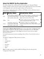
1
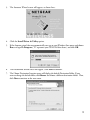
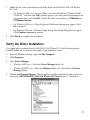
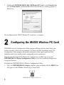
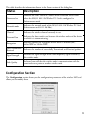
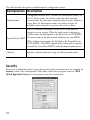
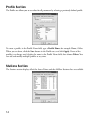
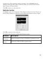
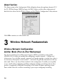
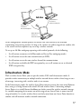
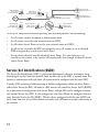
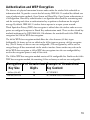
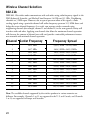
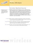
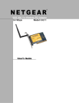
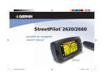
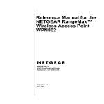
802.11b Wireless PC Card
2.4 GHz MA521
User's Guide
Introduction
Congratulations on your purchase of NETGEAR MA521 802.11b Wireless PC Card. With
this PC Card you will get ultimate mobility at home, in your office, or while you are traveling,
and it frees you from traditional Ethernet wiring.
This user’s guide shows you how to connect the PC Card and configure it with your access
point. Setup is easy – follow the instruction in this guide and your system will be up and
running quickly.
Package Contents
Wireless PC Card
32-bit CardBus MA521
802.11b • 2.4GHz
Resource CD, User's Guide,
Warranty card and Support information card
MA521 802.11b Wireless PC Card
The product package should contain:
•
MA521 802.11b Wireless PC Card
•
MA521 Resource CD
•
User’s guide
•
Warranty card
•
Support information card
System Requirements
Before installing the MA521 802.11b Wireless PC Card, please make sure that your computer
system has the following:
•
A computer with a 32-bit CardBus slot.
•
Please note that not all laptop or portable computer PC Card slots are CardBus, please
check your computer’s reference guide for more details.
1
•
Windows 98/Me/2000/XP (be sure to have the Windows Installation CD-ROM ready for
use during installation).
•
At least 5 Mbytes disk space for installing the driver and utility programs.
LED Indicators
There are two LEDs on the MA521 802.11b Wireless PC Card: Pwr and Lnk. The green Pwr
LED indicates the power of the card. The green Lnk LED indicates the wireless link condition
of the station with another wireless node or the associated Access Point.
LED Activity
Meaning of LED Activity
Pwr
The Pwr indicator lights green when the MA521 802.11b
Wireless PC Card is receiving power, otherwise, it is off.
Lnk
The Lnk indicator steady green when the MA521 802.11b
Wireless PC Card is connected to a network successfully.
Otherwise the Lnk indicator is off.
1
Installing the MA521 Wireless PC Card
IMPORTANT NOTE: You must first install the software before you plug the card into
your computer!
Follow these steps to install the MA521 802.11b Wireless PC Card.
Install the MA521 Driver and Utility Software
1.
Turn on your computer.
2.
Insert the MA521 Resource CD into the CD-ROM drive.
2
3.
The Autostart Wizard screen will appear, as shown here:
4.
Click the Install Driver & Utility option.
5.
If the Autorun wizard does not automatically start, go to your Windows Start menu and choose
Run, and type D:/Setup.exe (“D” represents your CD-ROM drive letter), and click OK.
6.
The InstallShield Wizard screen will appear. Click Next to continue.
7.
The Choose Destination Location screen will display the default Destination Folder. If you
want to change the default folder, click Browse and choose a different destination folder. Then,
click Next to continue to the next screen.
3
8.
Modify the Program Folders field, if desired. Click Next to continue. Install Shield will start
copying files onto your system.
9.
Click Finish to complete installing the Configuration Utility.
Install the MA521 Wireless PC Card
1.
Insert the MA521 802.11b Wireless PC Card into an available CardBus slot on your computer
as shown here.
80
2.1
1b
-b
ar
us
ss
dB
ele
C
ir
it
W
2
H
z
3
•2
.4
G
M
A
PC
2
a
1
C
5
rd
MA521 Wireless PC Card
in a Notebook Computer
2.
4
Windows will automatically detect the MA521 802.11b Wireless PC Card and the Found New
Hardware Wizard dialog box will appear.
3.
4.
Follow the on-screen instructions to install the driver for the MA521 802.11b Wireless
PC Card.
•
For Windows 98/Me users, once the [Please insert the disk labeled “Windows 98/Me
CD-ROM,” and then click OK] window appears, enter the path corresponding to the
appropriate drives and click OK. Usually these files can be found at C:\Windows or
C:\Windows\System.
•
For Windows 2000 users, a Digital Signature Not Found message may appear. Click
Yes to proceed.
•
For Windows XP users, a Windows Logo Testing Not Found dialog box may appear.
Click Continue Anyway to proceed.
Click Finish to complete the installation.
Verify the Driver Installation
It is a good idea to confirm that the MA521 802.11b Wireless PC Card has been properly
installed. Follow the instructions that apply to your computer system:
1.
From the Windows desktop, right-click My Computer.
2.
Click Properties.
3.
Open Device Manager:
4.
•
Windows 98/Me users – Select the Device Manager folder tab.
•
Windows 2000/XP users – Select the Hardware folder tab, and click on the Device
Manager button.
Double-click Network Adapters. There should be no yellow exclamation mark or red cross
icon on the NETGEAR MA521 802.11b Wireless PC Card selection, as shown here.
5
5.
Double-click NETGEAR MA521 802.11b Wireless PC Card. On the General folder
tab, the Device Status window should indicate that the device is working properly, as
shown here:
The installation of the MA521 Wireless PC Card driver is complete.
2
Configuring the MA521 Wireless PC Card
NETGEAR’s wireless Configuration Utility program will help you learn more about your
wireless network, so that you can customize it to better suit your networking needs. The
Configuration Utility program will provide information about signal quality and link
conditions and let you modify various configurable wireless parameters.
Now that the MA521 802.11b Wireless PC Card has been installed, you can use the
NETGEAR MA521 Wireless Configuration Utility to view and customize configuration
settings and features.
To display the NETGEAR MA521 Wireless Configuration Utility:
•
Open the NETGEAR MA521 Adapter programs group or double-click the MA521 icon
that appears in the Windows System Tray, as shown here:
MA521 Wireless Adapter SysTray icon
6
About the MA521 SysTray Application
The SysTray (System Tray) resides on one end of the taskbar in the Microsoft Windows
Desktop. It displays interface icons for memory-resident applications that execute continuously
in the background, such as the clock, speaker volume, and virus detection.
Once you have completed the utility installation, the Windows SysTray will show the icon in
different colors, as described here:
Color Ad-Hoc Mode
Infrastructure Mode
Red
Red The Wireless Adapter has Either the Wireless Adapter is not able to link to any
not initiated communication Access Point, or the link between the Wireless
with any other wireless node. Adapter and the Access Point is lost.
Yellow
N/A
The link condition between the Wireless Adapter
and the associated Access Point is weak.
Green
The Wireless Adapter has
communicated successfully
with another wireless node.
The Wireless Adapter has established good
communication with an Access Point and the signal
is strong.
Double-click the Wireless Adapter SysTray icon to activate the wireless Configuration Utility
for the MA521 Wireless PC Card. You can click any of the folder tabs in the NETGEAR
MA521 Wireless Configuration Utility dialog box to view the current status or modify
operational parameters.
For detailed information on wireless networking, refer to Wireless Network Fundamentals, on
page 16.
The MA521 Configuration Utility contains six sections:
•
Status
•
Configuration
•
Profile
•
Site Survey
•
Statistics
•
About
Note: The above sections are always available by clicking on the tab at the top of the
Configuration Utility window.
7
Configuration Note for Windows XP Users
By default, Windows XP uses its own utility to configure your wireless network settings,
however, in order to take advantage of the MA521 features and functions, we recommend that
you use the NETGEAR MA521 Wireless Configuration Utility program.
After installing the MA521 Wireless PC Card on the Windows XP, it will display a Disable
Windows XP Configuration Manager message, similar to the one shown here:
Click Yes to disable the Windows XP configuration utility and use the NETGEAR MA521
Wireless Configuration Utility, or click No to use the Windows XP configuration utility to
control the MA521 802.11b Wireless PC Card.
Status Section
The Status section of the NETGEAR MA521 Wireless Configuration Utility dialog box shows
the current wireless LAN connection status, statistics of data transmitted and received, signal
strength, etc., as shown here.
8
This table describes the information shown in the Status section of the dialog box:
Status
Description
Connected to
Indicates the SSID and MAC address of the associated Access Point
when the MA521 802.11b Wireless PC Card is configured in
Infrastructure mode.
Network mode
Indicates the network mode of the MA521 802.11b Wireless PC Card
(Infrastructure or 802.11 Ad-Hoc).
Channel
Indicates the wireless channel currently in use.
Transmit Rate
Indicates the data transfer rate between the wireless node and the device
to which it is communicating.
Encryption
Indicates whether the encryption of this device is disabled (off ),
64-bit WEP or 128-bit WEP.
Data Transmitted/
Received
Indicates the number of successfully Transmitted and Received packets.
Signal Strength
Indicates the signal strength of the radio frequency signal received by
this wireless node.
Link Quality
Indicates how well that the wireless node is communication with the
associated access point or another wireless node.
Configuration Section
The Configuration section shows you the configuration parameters of the wireless LAN and
allows you to modify them.
9
This table describes the options available from the Configuration section:
Configuration Description
Network mode
Configurable between 802.11 Ad-hoc and Infrastructure modes. In
802.11 Ad-hoc mode, the wireless nodes form their own local
network where the end nodes communicate peer-to-peer without an
Access Point. In Infrastructure mode, the wireless searches all
available wireless channels to associate with an Access Point.
Enter a 32-character (maximum) Service Set ID in this field; the
characters are case sensitive. When the wireless node is operating in
Ad-Hoc mode, this field operates as the Basic Service Set ID (BSSID).
Network Name (SSID) All wireless nodes in the same network should use the same BSSID.
When in Infrastructure mode, this field defines the Extended Service
Set ID (ESSID). The ESSID assigned to the wireless node is required
to match the Access Point ESSID in order for them to communicate.
Channel
Specifies a channel only when using an Ad-hoc network mode.
Security
To prevent unauthorized wireless stations from accessing data transmitted over the network, the
Security section of the Configuration Utility offers secure data encryption, known as WEP
(Wired Equivalent Privacy), to better protect your data transmissions.
10
To activate the WEP Encryption, make sure the Enable Encryption box displays a checkmark
(as shown on previous page).
WEP Encryption options will be displayed, as shown on the previous page. You may make
changes, as detailed here:
1.
Select one of the two options: Create with Passphrase or Manual Entry. A Passphrase
makes you easier to enable WEP because it automatically generates the WEP hexadecimal
numbers for the key. If the wireless network Access Point uses a Passphrase, you can also
use that here. Otherwise, you will have to manually enter the hexadecimal numbers.
2.
Create with Passphrase option: pull down the Key Length options and select the 64-bit
or 128-bit, then type in your Passphrase.
3.
Manual Entry option:
•
Pull down the Key Length options and select the 64-bit or 128-bit, encryption method.
•
In the Encryption Keys fields, specify the WEP keys:
For 64-bit encryption:
Hexadecimal: 10 hexadecimal digits in the range of “A-F”, “a-f ”
and “0-9” (e.g. 11AA22BB33)
For 128-bit encryption:
Hexadecimal: 26 hexadecimal digits in the range of “A-F”, “a-f ” and
“0-9” (e.g. 00112233445566778899AABBCC).
4.
When you are done, click the Apply button and click OK for the changes to take effect.
Important Note: The WEP keys must be set up exactly the same on all wireless devices in
order to communicate with each other.
11
This table describes the options available from the Security section:
Security
Description
Enable Encryption
Enables the data encryption for the wireless node. If you disable the
data encryption (by unchecking the box) then no encryption method
will be used; this is also called Open System data encryption. To enable
encryption is to use the Shared Key data encryption method.
Create with
Passphrase
A Passphrase is use to automatically generate the WEP hexadecimal
numbers for the key. If your wireless network Access Point uses a
Passphrase, you can use that here.
Once you type in the Passphrase, the generated key will be shown
before you click OK or Apply button.
Manual Entry
The WEP hexadecimal numbers are needed if a Passphrase is not used
in the wireless Access Point but rather if the key is manually entered.
Key Length
The key length must be the same between all wireless nodes and Access
Points in the same network. The possible values for the data encryption
level are 64-bit and 128-bit. The 64-bit data encryption is also called
40-bit data encryption by some vendors.
Key3
The MA521 device uses a selected WEP key to encrypt and decrypt
information. When set to 64-bit (also called 40-bit), or 128-bit data
encryption mode, you may specify up to four different keys to encrypt
wireless data.
Key4
Select one of the keys as a default key.
Key1
Key2
Advanced Settings
The advanced settings give you flexibility to control your
MA521 card to adjust with an access point or other client
devices in certain environment.
12
This table describes the options available from the Security section:
Status
Description
Transmit Rate
The Transmit Rate field allows to define the data transfer rate. The
default value if Fully Automatic. In this case, the best transfer rate is
negotiated between this wireless node and access point or another
wireless note that it is communicating with. Other option values for
this field are 1, 2, 5.5 and 11 Mbps.
Power Saving
Power saving options are Off, Normal, and Maximum. Power saving is
disable when Ad-Hoc mode is selected in the Network Mode field.
When the Power Saving setting is Off, the adapter receives full power
from the PC. When the setting is Normal, the driver turns off power to
the MA521 Wireless PC Card for brief periods over briefly-spaced time
intervals. When the setting is Maximum, the driver turns off power to
the MA521 Wireless PC Card for longer periods over more widelyspaced time intervals.
Transmit Power
This option controls the Radio Frequency (RF) output power. Selects
100%, 50%, 25%, 12.5%, or Minimum.
Preamble Type
A long transmit preamble allows the receiver (MA521 Wireless PC Card)
to lock into the received bit patterns more easily. A short transmit
preamble provides better performance. Default: Auto (long & short).
Fragmentation
Threshold
This is the packet length used for fragmentation. Packets larger than
the size programmed in this field will be fragmented. The
Fragmentation Threshold value must be larger than RTS Threshold
value. The default value for Fragmentation Threshold is 2432.
RTS/CTS
Threshold
The packet size that wireless node uses to determine if it should use the
CDMA/CD mechanism or the CSMA/CA mechanism for packet
transmission. With the CSMA/CD transmission mechanism, the
transmitting station sends out the actual packet as soon as it has waited
for the silence period. With the CSMA/CA transmission mechanism, the
transmitting station sends out a RTS packet to the receiving station,
waits for the receiving station to send back a CTS packet before sending
the actual packet data. The default value for RTS Threshold is 2432.
13
Profile Section
The Profile area allows you to set values for all parameters by selecting a previously defined profile.
To create a profile, in the Profile Name field, type a Profile Name; for example: Home, Office.
When you are done, click the Save button in the Profile area, and click Apply. If one of the
profiles is no longer used, display the name in the Profile Name field, then choose Delete. You
can add and modify multiple profiles at any time.
Stations Section
The Stations section displays all of the Access Points and the Ad-Hoc Stations that are available.
14
To display Access Points around the working environment, select the Re-Scan button. In
addition to showing the MAC Address of each Access Point, you can also view the Channel,
Signal, Security, and Network Modes.
Click OK to continue, or select another tab.
Statistics Section
The Statistics section of the Configuration Utility dialog box indicates the real-time Transmit and
Receive packets performance in graph form and also displays the performance statistics in figures.
Click OK to continue or select another tab.
This table describes the options available from the Statistics section:
Statistics
Description
Transmit/Receive
Displays the maximum and current Tx/Rx (Kbits/sec) performance statistics.
Performance
Transmit/Receive
Monitors the Tx/Rx of the Kbits or packet statistics.
Statistics
15
About Section
The About section of the Configuration Utility dialog box shows the regulatory domain: FCC
for US, ETSI for Europe, MKK for Japan; the MAC address and the release information of
both the device driver for the Wireless Adapter and the Wireless Configuration Utility software.
Click OK to continue, or select another tab.
3
Wireless Network Fundamentals
Wireless Network Configuration
Ad-Hoc Mode (Peer-to-Peer Workgroup)
The Institute of Electrical and Electronics Engineers (IEEE) standard for wireless LANs
(WLANs), 802.11 offers two methods for configuring a wireless network — Ad-Hoc and
infrastructure. In an Ad-Hoc network, computers are brought together as needed; thus, there is
no structure or fixed points to the network — each node can generally communicate with any
other node. There is no Access Point involved in this configuration. It enables you to quickly
set up a small wireless workgroup and allows workgroup members to exchange data or share
printers as supported by Microsoft Networking in the various Windows operating systems.
Some vendors also refer to ad-hoc networking as peer-to-peer workgroup networking.
16
80
2.1
1b
-b
s
Bu
es
rd
el
Ca
ir
it
W
H
z
32
•2
.4
G
Ad-Hoc
s
M
a
21
C
A5
PC
rd
80
2.1
1b
MA521 Wireless
PC Card in a
Notebook Computer
-b
s
Bu
es
rd
el
Ca
ir
it
W
H
z
32
•2
.4
G
s
M
a
21
C
A5
PC
rd
MA521 Wireless
PC Card in a
Notebook Computer
80
2.1
1b
-b
s
Bu
es
rd
el
Ca
ir
it
W
H
z
32
•2
.4
G
MA521 Wireless
PC Card in a
Notebook Computer
s
M
a
21
C
A5
PC
rd
In this configuration, network packets are directly sent and received by the intended
transmitting and receiving stations. As long as the stations are within range of one another, this
is the easiest and least expensive way to set up a wireless network.
To set up an Ad-Hoc workgroup operating with standard protocols, do the following:
•
Set all stations to connect in Ad-Hoc mode (or Peer-to-Peer workgroup mode).
•
Set all stations to use the same network name (or SSID).
•
Set all stations to use the same wireless channel for communication.
•
Set all stations to disable the WEP encryption key, or set all stations to use an identical
WEP encryption key.
Infrastructure Mode
With a wireless Access Point, you can put the wireless LAN into Infrastructure mode. It
provides wireless connectivity to multiple wireless network devices within a fixed range or area
of coverage, interacting with a wireless node via an antenna.
In the Infrastructure mode, the wireless Access Point converts airwave data into wired Ethernet
data, acting as a bridge between the wired LAN and wireless clients. Connecting multiple
Access Points via a wired Ethernet backbone can further extend the wireless network coverage.
As a mobile computing device moves out of the range of one Access Point, it moves into the
range of another. As a result, wireless clients can freely roam from one Access Point domain to
another and still maintain seamless network connection.
17
Notebook PC with
MA111 802.11b
Wireless USB Adapter
Macintosh with
Ethernet connection
Desktop PC with
MA111 802.11b
Wireless USB Adapter
R
G E A
N E T
Internet
3
MR814 802.11b
Cable/DSL Wireless 4-port Router
Desktop PC with
FA311 Ethernet Card
Cable/DSL
Modem
Desktop PC with
MA321 802.11b
Wireless PCI Adapter
Notebook PC with
MA521 802.11b
Wireless PC Card
Notebook PC with
MA521 802.11b
Wireless PC Card
To set up an Infrastructure network operating with standard protocols, do the following:
•
Set all wireless stations to connect in Infrastructure mode.
•
Set all stations to use the same network name (or SSID).
•
Set all wireless Access Points to use the same network name (or ESSID).
•
Set all stations to disable the WEP encryption key, or set all stations to use an identical
WEP encryption key as used by the Access Point.
•
Set up wireless channels used by individual Access Points. (It is not necessary to set
channels on the stations as the stations will automatically scan through all channels for the
nearest Access Point.)
Service Set Identification (SSID)
The Service Set Identification (SSID) is a thirty-two alphanumeric character (maximum) string
identifying the wireless local area network. Some vendors refer to the SSID as network name. For
stations to communicate with each other, all stations must be configured with the same SSID.
A wireless LAN consisting of nodes operating in Ad-Hoc configuration without an Access Point is
called a Basic Service Set (BSS). All nodes in a BSS must use the same Basic Service Set ID (BSSID).
In an infrastructure configuration with Access Points, multiple BSS can be configured to form
an Extended Service Set (ESS). In this configuration, the Access Points are configured with the
same Extended Service Set ID (ESSID). Wireless clients configured with the same ESSID can
freely roam from one Access Point domain to another and still maintain seamless connection to
the network.
18
Authentication and WEP Encryption
The absence of a physical connection between nodes makes the wireless links vulnerable to
information theft. To provide a certain level of security, IEEE 802.11 standard has defined two
types of authentication methods, Open System and Shared Key. Open System authentication is
a null algorithm. Shared Key authentication is an algorithm where both the transmitting node
and the receiving node share an authentication key to perform a checksum on the original
message. By default, IEEE 802.11 wireless devices operate in an open system network.
Wired Equivalent Privacy (WEP) data encryption is utilized when the wireless nodes or access
points are configured to operate in Shared Key authentication mode. There are three shared key
methods implemented in NETGEAR 802.11b solutions: the standard based 64-bit WEP data
encryption and 128-bit WEP data encryption.
The 64-bit WEP data encryption method allows for a five-character (40 bits) input.
Additionally, 24 factory-set bits are added to the 40-bit input to generate a 64-bit encryption
key. (The 24 factory-set bits are not user configurable.) This encryption key will be used to
encrypt/decrypt all data transmitted via the wireless interface. Some vendors may refer to the
64-bit WEP data encryption as 40-bit WEP data encryption since the user configurable key
used in the encryption process is only 40 bits wide.
The 128-bit WEP data encryption method consists of 104 configurable bits. Similar to the 64-bit
WEP data encryption method, the remaining 24 bits are factory set and not user configurable.
Encryption # of Hexadecimal Example of Hexadecimal
Key Size
Digits
Key Content
64-bits (24+40)
10
4C72F08AE1
128-bit (24+104)
26
4C72F08AE19D57A3FF6B260037
19
Wireless Channel Selection
802.11b
IEEE 802.11b wireless nodes communicate with each other using radio frequency signals in the
ISM (Industrial, Scientific, and Medical) band between 2.4 GHz and 2.5 GHz. Neighboring
channels are 5 MHz apart. However, due to spread spectrum effect of the signals, a node
sending signals using a particular channel will utilize frequency spectrum 12.5 MHz above and
below the center channel frequency. As a result, two separate wireless networks using
neighboring channels (for example, channel 1 and channel 2) in the same general vicinity will
interfere with each other. Applying two channels that allow the maximum channel separation
will decrease the amount of channel cross talk, and provide a noticeable performance increase
over networks with minimal channel separation.
Channel Center Frequency
Frequency Spread
1
2412 MHz
2399.5 MHz – 2424.5 MHz
2
2417 MHz
2404.5 MHz –2429.5 MHz
3
4
2422 MHz
2427 MHz
2409.5 MHz –2434.5 MHz
2414.5 MHz –2439.5 MHz
5
2432 MHz
2419.5 MHz – 2444.5 MHz
6
7
2437 MHz
2442 MHz
2424.5 MHz –2449.5 MHz
2429.5 MHz –2454.5 MHz
8
2447 MHz
2434.5 MHz – 2459.5 MHz
9
10
2452 MHz
2457 MHz
2439.5 MHz –2464.5 MHz
2444.5 MHz –2469.5 MHz
11
2462 MHz
2449.5 MHz – 2474.5 MHz
12
2467 MHz
2454.5 MHz – 2479.5 MHz
13
2472 MHz
2459.5 MHz – 2484.5 MHz
Note: The available channels supported by the wireless products in various countries are
different. For example, Channels 1 to 11 are supported in the U.S. and Canada, and Channels
1 to 13 are supported in Europe and Australia.
20
Troubleshooting
Problem
Cause
Solution
• Remove and reinsert the MA521 Wireless
No lights are lit The MA521 Wireless PC
PC Card.
on the Wireless Card is not inserted
PC Card
properly into the CardBus • Check the device manager in Windows to see
slot on your PC. Or the
if the adapter card is properly recognized in
proper MA521 Wireless PC
the Windows operating system. Reload the
Card driver is not loaded.
driver if necessary.
• Try to install the MA521 Wireless PC Card
in different CardBus slot if it’s available.
The Lnk LED
is off
• The Access Point may not be powered on.
The MA521 Wireless PC
Card is not associated to
• The Access Point and the MA521 Wireless
any Access Point properly.
PC Card are not configured with the same
You may not have
wireless parameters. Check the SSID, and
configured the wireless
WEP encryption settings.
parameters of the wireless
nodes to be the same as the • The Access Point may be out of range. Try
moving the system closer to the Access Point
Access Point.
or readjusting the antenna on the Access
Point. You may also move the Access Point to
a higher location for better signal reception by
the MA521 Wireless PC Card.
• Check to make sure that the Access Point
I am associated This could be a physical
is physically connected to the Ethernet
and connected layer problem or a network
network.
to an Access
configuration problem.
Point, but I
• Make sure that the IP addresses and the
cannot see the
Windows networking parameters are all
other computers
configured correctly.
on the Ethernet
side of the
network.
21
Statement of Conditions
In the interest of improving internal design, operational function, and/or reliability, NETGEAR reserves the right to
make changes to the products described in this document without notice.NETGEAR does not assume any liability that
may occur due to the use or application of the product(s) or circuit layout(s) described herein.
Certificate of the Manufacturer/Importer
It is hereby certified that the Model MA521 Wireless PC Card has been suppressed in accordance with the conditions
set out in the BMPT- AmtsblVfg 243/1991 and Vfg 46/1992. The operation of some equipment (for example, test
transmitters) in accordance with the regulations may, however, be subject to certain restrictions. Please refer to the
notes in the operating instructions.
Federal Office for Telecommunications Approvals has been notified of the placing of this equipment on the market and
has been granted the right to test the series for compliance with the regulations.
VCCI Statement
This equipment is in the Class B category (information equipment to be used in a residential area or an adjacent area
thereto) and conforms to the standards set by the Voluntary Control Council for Interference by Data Processing
Equipment and Electronic Office Machines aimed at preventing radio interference in such residential areas. When used
near a radio or TV receiver, it may become the cause of radio interference. Read instructions for correct handling.
Federal Communications Commission (FCC) Compliance Notice:
Radio Frequency Notice
This device complies with part 15 of the FCC Rules. Operation is subject to the following two conditions:
1. This device may not cause harmful interference.
2. This device must accept any interference received, including interference that may cause undesired operation.
NETGEAR MA521 Wireless PC Card
Tested to Comply
with FCC Standards
FOR HOME OR OFFICE USE
Warning!
To comply with the FCC's rf exposure requirements you must
maintain a distance of at least 1 cm from the with FCC Standards
antenna of this device while it is in use. This device should not be colocated with other transmitters.
Note: This equipment has been tested and found to comply with the limits for a Class B digital device, pursuant to
part 15 of the FCC Rules. These limits are designed to provide reasonable protection against harmful interference in a
residential installation. This equipment generates, uses, and can radiate radio frequency energy and, if not installed and
used in accordance with the instructions, may cause harmful interference to radio communications. However, there is
no guarantee that interference will not occur in a particular installation. If this equipment does cause harmful
interference to radio or television reception, which can be determined by turning the equipment off and on, the user is
encouraged to try to correct the interference by one or more of the following measures: (1) Reorient or relocate the
receiving antenna, (2) Increase the separation between the equipment and receiver, (3) Connect the equipment into an
outlet on a circuit different from that to which the receiver is connected, (4) Consult the dealer or an experienced
radio/TV technician for help.
Federal Communications Commission (FCC) Radiation Exposure Statement
This equipment complies with FCC radiation exposure limits set forth for an uncontrolled environment. In order to
avoid the possibility of exceeding the FCC radio frequency exposure limits, human proximity to the antenna shall not
be less than 20 cm (8 inches) during normal operation.
EN 55 022 Declaration of Conformance
This is to certify that the NETGEAR Model MA521Wireless PC Card is shielded against the generation of radio
interference in accordance with the application of Council Directive 89/336/EEC, Article 4a. Conformity is declared
by the application of EN 55 022 Class B (CISPR 22).
22
Canadian Department of Communications Radio Interference Regulations
This digital apparatus (Model MA521 Wireless PC Card) does not exceed the Class B limits for radio-noise emissions
from digital apparatus as set out in the Radio Interference Regulations of the Canadian Department of
Communications.
Règlement sur le brouillage radioélectrique du ministère des Communications
Cet appareil numerique (NETGEAR Model MA521 Wireless PC Card) respecte les limites de bruits radioelectriques
visant les appareils numeriques de classe B prescrites dans le Reglement sur le brouillage radioelectrique du ministere
des Communications du Canada.
Bestätigung des Herstellers/Importeurs
Es wird hiermit bestatigt, daß das Model MA521 Wireless PC Card gemaß der im BMPT-AmtsblVfg 243/1991 und
Vfg 46/1992 aufgefuhrten Bestimmungen entstort ist. Das vorschriftsmaßige Betreiben einiger Gerate (z.B. Testsender)
kann jedoch gewissen Beschrankungen unterliegen. Lesen Sie dazu bitte die Anmerkungen in der Betriebsanleitung.
Das Bundesamt fur Zulassungen in der Telekommunikation wurde davon unterrichtet, daß dieses Gerat auf den Markt
gebracht wurde und es ist berechtigt, die Serie auf die Erfullung der Vorschriften hin zu uberprufen.
0470 !
Achtung: Dieses Produkt ist für die Schweiz und alle EU-Staaten mit Ausnahm.
Attention: This product is certified for Switzerland and all EU-countries.
23
Technical Support
PLEASE REFER TO THE SUPPORT INFORMATION CARD THAT SHIPPED WITH
YOUR PRODUCT.
By registering your product at www.NETGEAR.com/register, we can provide you with faster
expert technical support and timely notices of product and software upgrades.
NETGEAR, INC.
Support Information
Phone: 1-888-NETGEAR (For US & Canada only) - 24x7 phone support
See Support Information card for other countries.
E-mail: [email protected] (24x7 online support)
www.NETGEAR.com
©2003 NETGEAR, Inc. NETGEAR, the Netgear logo, The Gear Guy, Auto Uplink and
Everybody's Connecting are trademarks or registered trademarks of Netgear, Inc. in the United
States and/or other countries. Microsoft and Windows are registered trademarks of Microsoft
Corporation in the United States and/or other countries. Other brand and product names are
trademarks or registered trademarks of their respective holders. Information is subject to change
without notice. All rights reserved.
April 2003