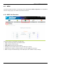
1
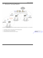
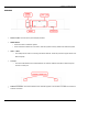
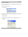
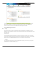
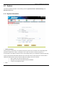
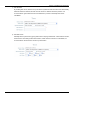
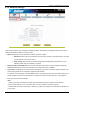
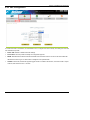
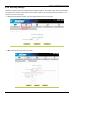
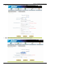
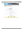
NP725 - Wireless Access Point NP725 User Guide www.netcomm.com.au User Guide Table of Contents Chapter 1. Introduction .......................................................................................................................................1 1.1 Overview ...................................................................................................................................................1 1.2 Product Features ........................................................................................................................................1 1.3 Deployment Topology Examples...............................................................................................................2 Chapter 2. System Overview ................................................................................................................................3 2.1 Package Contents.......................................................................................................................................3 2.2 Hardware ...................................................................................................................................................3 2.3 System Requirement and Preparation........................................................................................................5 Chapter 3. Installation .........................................................................................................................................6 3.1 Wireless LAN Access Point Connection ...................................................................................................6 3.2 Basic Configuration ...................................................................................................................................7 Chapter 4. 4.1 Web Management Interface ............................................................................................................17 System .....................................................................................................................................................20 4.1.1 System Information .........................................................................................................................................20 4.1.2 Network Settings .............................................................................................................................................23 4.1.3 Management Services ......................................................................................................................................24 4.2 AP ............................................................................................................................................................25 4.2.1 Virtual AP Overview........................................................................................................................................25 4.2.2 General Settings...............................................................................................................................................28 4.2.3 VAP Configuration...........................................................................................................................................29 4.2.4 Security Settings ..............................................................................................................................................30 4.2.5 Advanced Wireless Settings.............................................................................................................................33 4.2.6 Access Control Settings ...................................................................................................................................34 4.3 WDS ........................................................................................................................................................37 4.3.1 WDS Link Overview .......................................................................................................................................37 4.3.2 WDS Link Settings ..........................................................................................................................................38 4.4 Utilities ....................................................................................................................................................39 4.4.1 Change Password.............................................................................................................................................39 4.4.2 Configuration Save / Restore...........................................................................................................................40 4.4.3 System Upgrade...............................................................................................................................................41 4.4.4 Reboot..............................................................................................................................................................42 4.5 Status .......................................................................................................................................................43 4.5.1 System Overview.............................................................................................................................................43 4.5.2 Associated Client Status ..................................................................................................................................45 4.5.3 WDS List Status ..............................................................................................................................................46 4.5.4 Event Log ........................................................................................................................................................47 4.6 Online Help..............................................................................................................................................48 4.7 Legal & Regulatory Information .............................................................................................................48 Chapter 1. Introduction Chapter 1. 1.1 Introduction Overview This manual is written to assist system integrators, field engineers and network administrators in setting set up NetComm NP725 Access Points in their network environments. It contains step by step procedures and pictures to guide users with basic network system knowledge to complete the installation. NP725 is a Multi-Mode Access Point, specially designed for connecting wireless networks for wider coverage. NP725 provides features of Access Point (AP) and Wireless Distribution System (WDS) simultaneously. In the Access Point mode, it supports up to eight Virtual Access Points (VAPs) which could provide service in different levels and much securer network. NP725 Access Point also supports the most popular wireless authentication and encryption standards which make flexible security policy possible by taking advantage of these Virtual Access Points. Thus, there is an independent rule setting for each Virtual Access Point that can be defined to meet the actual requirements. In the Wireless Distribution System mode, it supports point-to-point or point-to-multipoint topology, which could widely extend the wireless coverage. 1.2 Product Features High Speed IEEE 802.11g and Backward Compatible with 802.11b IEEE 802.11b/g + WDS (Bridge & Repeater, Point-to-Point, Point-to-Multiple-Point) Dual IEEE 802.3af (PoE) Compliant with Link Failover Multiple ESSIDs Capability WDS for Extending Wireless Coverage Supporting QoS & 802.11e WMM Multiple Virtual APs & Capability of Client Isolation Business-class WLAN Security & Client Authentications Multiple Administration Interfaces for Network Management Dual-PoE with Link Failover Antenna Diversity & detachable Antenna IP50 Compliant 1 Chapter 1. Introduction 1.3 Deployment Topology Examples The above deployment scenario illustrates a deployment example using three access points, AP-1, AP-2 and AP-3. Three NP725s construct a network with wired and wireless segments. The AP-2 plays the role as a wireless bridge. All machines share the same DHCP server 192.168.1.1. Formatted: Bullets and Numbering 2 Chapter 2. System Overview Chapter 2. 2.1 System Overview Package Contents The standard package of NP725 includes: y NP725 x 1 y CD-ROM with product User Manual x 1 y Console Cable DB9 Female to DB9 Male x 1 y Straight through Ethernet Cable x 1 y Power Adapter 12V, 1.5A x 1 y 2dBi Antenna x 2 y Mounting Kit x 1 y Ground Cable x 1 Note: It is recommended to keep the original packing materials in case of product service requirements. Any returned product should be packed according to its original package content, together with its relevant packing materials used for protecting the equipment from damage during delivery. 2.2 Hardware On the top panel of the product, there are four LEDs that are used to indicate the system power, WLAN status, and the link status of the two PoE Fast Ethernet ports. On the front panel, there are one power socket, one reset button, two PoE LAN ports and one console port. The antenna is installed on the rear panel. 3 Chapter 2. System Overview Rear Panel Power Socket: Connects to the power adapter provided. RESET Button o Press the button to restart the system. o Press and hold the button for 5 seconds to reset the system to factory default and restart the system. LAN 1 / LAN2: o The LAN ports are used for connecting with wired networks. These two ports also support Power over Ethernet (PoE). Console: o The serial cable attaches here. Administrators can obtain IP address information of Ethernet ports from the console port. Antenna Connector: The antenna attaches here. NP725 supports 1 RF interface and 2 SMA connectors for antenna connection. 4 Chapter 2. System Overview Top Panel LED: Power: ON indicates that power is on and OFF indicates that power is off. LAN1/LAN2: OFF indicates no connection, ON indicates connection and BLINKING indicates transmitting data. 2.3 WLAN: ON indicates system is ready. System Requirement and Preparation Preparations A computer is needed to configure NP725 via its web management interface. After completing hardware installation, the administrator can configure the NP725 via web browser with JavaScript enabled, such as Mozilla Firefox 2.0 or Internet Explorer version 6.0 and the above. The default LAN IP address of NP725 is listed as following: IP Address: 192.168.25.1 Subnet mask: 255.255.255.0 If the IP address of the administrator’s PC is not assigned via DHCP, then a static IP address assigned to the administrator’s computer within the same subnet as NP725 is needed. The following listed Address as examples: IP Address: 192.168.25.100 Subnet mask: 255.255.255.0 Note: Please refer to LEDs of the switch hub to verify the wired connection of both sides. After NP725's network configuration completes, please switch back the original settings to fit the real network environment. 5 Chapter 3. Installation Chapter 3. 3.1 Installation Wireless LAN Access Point Connection Please follow the steps below to install the hardware of NP725. 1. Locate the wireless LAN access point at the best location. The best location for NP725 is usually at the center of a wireless network. 2. Connect the wireless LAN access point to your other network equipment. Connect an Ethernet cable to the NP725’s LAN port and connect the other end of the cable to a switch, a router, or a hub. The access point will be connected to your existing wired LAN network. 3. There are two options to supply power to NP725. 1) Connect the DC power adapter to the power socket. Please note that using a different adapter may damage the product. 2) Connect a PoE capable device (switch or PSE) to the LAN port. Now, the Hardware Installation has been completed. Note: 1. Please refer to LEDs of the switch/hub to verify the wired connection of both sides. 2. Dual LAN ports can be used for power failover, but there could be a problem with dual data links in the same LAN environment, unless appropriate Layer 2 STP configuration has been made for the entire network. Please refer to 4.1.2 Network Settings (Layer 2 STP) for more information. 6 Chapter 3. Installation 3.2 Basic Configuration NP725 provides the web management interface for configuration. After completing hardware installation, the administrator can configure the NP725 via web browsers with JavaScript enabled, such as Mozilla Firefox 2.0 or Internet Explorer version 6.0 and the above. The default LAN IP address of NP725 is listed as follows: IP Address: 192.168.25.1 Subnet Mask: 255.255.255.0 If the IP address of the administrator’s PC is not assigned via DHCP within the same subnet as NP725’s, then a static IP address assigned to the administrator’s computer within the same subnet as NP725’s is needed. The following IP address is listed as an example: IP Address: 192.168.25.100 Subnet Mask: 255.255.255.0 Once NP725 has been connected, the Administrator Login Page will appear. Enter “admin” for both the default user name and password in the User name and Password fields, and then click the OK button to log in. User name: admin Password: admin 7 Chapter 3. Installation After successfully logging into NP725, the System Overview page of the web management interface will appear. To logout, simply click the Logout icon on the upper right corner of the interface to return to the Administrator Login Page. Change Password: 1) Change administrator's password by clicking on the Utilities menu item. 2) Select Admin Password from submenu item. 3) Enter new password. Supply new password with length less than 30 characters, and then click on Apply to confirm the change. 8 Chapter 3. Installation Configure AP Settings 1) Click on the AP menu item. Select General submenu. 2) Determine the Band and Channel Select preferred Band and Channel for the wireless connection. For example, band is selected to 802.11b+802.11g and channel to 6. Check VAP Profile Settings 1) Select VAP Configuration submenu to configure. 2) Administrator can enable or disable specific VAP from the drop down list of “Profile Name”. NP725 supports up to 8 virtual APs. Note: To configure the rest of the profiles, please follow the same steps as illustrated for VAP-1. 9 Chapter 3. Installation Check AP Status After finishing the settings, the enabled virtual AP should appear in the virtual AP list showing enabled state. Choose Security Type 1) Select AP menu. 2) Select Security submenu to continue. 10 Chapter 3. Installation Change Security Type to WEP If WEP is preferred, supply the desired Authentication, key length, format, index and values. See the screen as an example. 11 Chapter 3. Installation Change Security Type to 802.1X If 802.1X authentication is preferred, supply the desired WEP key length and the corresponding settings of RADIUS server. 12 Chapter 3. Installation Change Security Type to WPA-PSK If WPA-PSK is preferred, supply the desired pre-shared key and cipher type. 13 Chapter 3. Installation Change Security Type to WPA-Radius If WPA-Radius is preferred, supply the cipher type and the corresponding settings of RADIUS server. 14 Chapter 3. Installation Configure WDS Settings 1) Click on the WDS menu item. 2) Select WDS Configuration submenu item. 3) Setting WDS link parameters By default, WDS profiles are disabled. First, choose the WDS Profile; enable WDS; supply peer’s MAC address and security type. Configure the Peer The WDS peer’s setting should be configured while completing the WDS configuration. To configure the peer, repeat the above WDS steps except for the last step that the MAC address information comes from the first WDS station. Obtain WDS List Status 1) Select the menu of Status. 2) Select WDS List submenu. 3) Check the signal strength of WDS link. Check the SNR of WDS link after clicking Status / WDS List, there should be SNR displayed; If the SNR is shown as N/A, the wiring and the above configuration should be checked again. 15 Chapter 3. Installation Congratulations Now, the system has been installed and configured successfully. Note: It is strongly recommended to make a copy of configuration backup. 16 Chapter 4. Web Management Interface Chapter 4. Web Management Interface This chapter provides further information on the NP725 configuration. The following table shows all the UI functions of NP725 Access Point. In the web management interface, there are main interface areas: Main Menu and Working Area. The Working Area occupies the largest area of the web interface in the center. It is also referred as the current management page. The current management is the page where status is displayed, where controlled is issued and parameters are configured. Main Menu, on the top of the web management interface, allows administrators to traverse to various management functions of this system. The management functions are grouped into branches: System, AP, WDS, Utilities and Status. OPTION FUNCTION System System Information Network Settings Management Services AP Virtual AP Overview General Settings VAP Configuration Security Settings Advanced Wireless Settings Access Control Settings WDS WDS Link Overview WDS Link Settings Utilities Change Password Configuration Save/Restore System Upgrade Reboot Status System Overview Associated Client Status WDS Link Status Event Log Caution: After finishing the configuration, please click Apply and pay attention to see if a restart message appears on screen. If the message appears, the system must be restarted to allow the settings to take effect. All on-line users will be disconnected during restart. 17 Chapter 4. Web Management Interface Introduction: NP725 has equipped a friendly Web graphical user interface for users and system administrators to configure parameters easily and remotely. The recommended web browsers are IE 6.0(TM), Firefox 2.0(TM) and the above. NP725 provides the web management interface for easier configuration. After completing hardware installation, the administrator can configure the NP725 through web browsers with JavaScript enabled, such as Mozilla Firefox 2.0 or Internet Explorer version 6.0 and the above. 1. Launch a web browser to access the web management interface of NP725 by entering “http://192.168.25.1” in the URL. The default LAN IP address of NP725 is listed as following: IP Address: 192.168.25.1 Subnet Mask: 255.255.255.0 If the IP address of the administrator’s PC is not assigned via DHCP within the same subnet as NP725’s, then a static IP address assigned to the administrator’s computer within the same subnet as NP725’s is needed. The following examples show how to set a static IP address to the administrator’s computer: IP Address: 192.168.25.100 Subnet Mask: 255.255.255.0 The Web management function of NP725 includes: System : System Information, Network Settings, Management Services AP: Overview, General, VAP Configuration, Security, Advanced, and Access Control. WDS: Overview and WDS Configuration Utilities: Admin Password, Configuration Save/Restore, System Upgrade and Reboot Status: Overview, Clients, WDS List and Event Log 18 Chapter 4. Web Management Interface In each configuration page, the active menu and submenu item will be shown in different color to indicate which function is working on. For example, as in the above figure, the screen is now in Status menu. And for each menu item, there are several tabbed sub-menus displayed underneath. Log into Web Management Interface: Login Once NP725 has been connected, the Administrator Login Page will appear. Enter “admin” for both the default user name and password in the User name and Password fields, and then click the OK button to log in User name: admin Password: admin The above default identity data is expected to be used once at first time, for security concern, it is strongly recommended to change the administrator's password after configuration being completed. After successfully logging into NP725, the System Overview page of the web management interface will appear. Logout To log out the web management page, press the Logout button at upper-right corner to log out the system. Click OK when the confirmation window pops up. 19 Chapter 4. Web Management Interface 4.1 System This section provides information on the following functions: System Information, Network Settings, and Management Services. 4.1.1 System Information System Information For the purpose of maintenance, it is required to specify the system name, its location and corresponding basic parameters. Fields such as “Name”, “Description” and “Location” are used for mnemonic purpose. It is recommended to have different values for each AP. Time settings allows you to set NP725’s system time manually or have it synchronized automatically with NTP server. When NTP server is used, NTP server1 must be filled. If FQDN (full qualified domain name) is used, the DNS server setting must also be activated. ¾ Name: System name used to identify this box ¾ Description: Give further information about this installation ¾ Location: The geographic location Time 20 Chapter 4. Web Management Interface ¾ Device Time: Current system time ¾ Time Zone: Take UTC offset to set this field ¾ Synchronization: There are two options of setting system time 21 Chapter 4. Web Management Interface 1) NTP Enabled: By enabling NTP server, NP725 can synchronize its system time with the NTP server automatically. While this method is selected, at least one NTP server's IP address should be provided. It is recommended to give both NTP servers' IP addresses to prevent occasionally NTP service unavailable. 2) Set Date & Time: Manually set the system time by giving date & time in this page underneath. If this method is chosen, the NTP server 1&2 settings will be closed. Note, unless Internet connection is unavailable, it is recommended to use NTP server for time synchronization. 22 Chapter 4. Web Management Interface 4.1.2 Network Settings There are two methods of IP configuration available in NP725. LAN interface configuration determines the way to obtain the IP address by DHCP or manually setup. Mode: Determine the way to obtain the IP address, by DHCP or Static. o DHCP client: This option is provided when the users have a DHCP in the wired network, and make sure the network connection is correct. o Static setting: Static setting is to set these parameters manually. Basic parameters such as IP address, subnet mask, and gateway are needed. Primary and Secondary DNS Server: If any host information in the system is given in FQDN format (Fully Qualified Domain Name), please ensure at least one of these DNS server is available. Layer 2 STP: The Spanning Tree Protocol (STP) eliminates Layer 2 loops in wired and wireless networks. The access point typically can be configured to bridge several networks. For example, if it is configured to construct WDS networks, it is possible to get loops in the wireless networks. As another example, when the two LAN ports are connected to the same LAN environment, it is also likely that there are loops in the wired networks. Note: 1. When Layer 2 STP is enabled, the system will automatically suspend a connection in the networks once the system detects a loop. If this is the case, one of the network connections could fail. 2. Please make sure that the other Layer 2 devices (e.g. switch) also support and enable STP, to eliminate the Layer 2 loops. 23 Chapter 4. Web Management Interface 4.1.3 Management Services For easier maintenance, SNMP (Simple Network Management Protocol) and remote syslog services are provided in NP725. VLAN for Management: The management traffic from the device can be tagged with VLAN ID. If the option is enabled, the VLAN ID can be chosen from 1 to 4094. SNMP Configuration: By enabling SNMP service, the remote SNMP manager could obtain NP725’s system status. o o Community String: Specify the password for Read and Write. Trap: Enable or Disable the feature. When enabled, its reported event will be sent to assigned management station with specified Server IP Address. Syslog Configuration: By enabling this service, specify a remote syslog server which could accept syslog messages from NP725 remotely. By reading the syslog message in the remote server, the administrator can review activities of all installed NP725s in the network. o Server Port: Port of the server. o Log Level: Select desired level of received events. 24 Chapter 4. Web Management Interface 4.2 AP This section provides information on the following functions: Overview, General, VAP Configuration, Security, Advanced and Access Control. The NP725 supports up to eight WLANs by Virtual Access Point (VAP). Each VAP can have its own settings including ESSID, VLAN ID, security settings, and etc. Therefore, these VAPs can bring different service level to clients depending on the ESSID connected to. Please click on the menu item AP to configure VAPs. 4.2.1 Virtual AP Overview The overall status is collected in this page, including enable/disable state, security type, MAC ACL state, and advanced settings. NP725 has 8 VAPs; each has its own setting. In the table, please click on the specific item to have detailed configuration of these VAPs respectively. State: The hyperlink showing enable or disable connects to the screen of VAP Configuration. 25 Chapter 4. Web Management Interface Security Type: The hyperlink showing security type connects to the screen of Security Settings. MAC ACL: The hyperlink showing status of MAC ACL connects to the screen of Access Control Settings. Advanced Settings: The hyperlink of advanced settings connects to the screen of Advanced Wireless Settings. 26 Chapter 4. Web Management Interface 27 Chapter 4. Web Management Interface 4.2.2 General Settings Band: The operating wireless frequency band of the device. Choose among frequency band Disable, 802.11b, 802.11g or mixed mode 802.11b+802.11g. Short Preamble: This option can be turned on to enable Short-Preamble frames. Channel: Choose from channel 1 ~ 13, depending on the region or auto. Max Transmit Rate: Choose transmit rate from the drop-down list. The maximum transmit rate can be set as “auto” or specific available rate under the chosen operating mode (802.11b, 802.11g or 802.11b+g). Transmit Power: Choose from Lowest Power to Highest Power level or auto. The item in this page is for AP's RF settings and will be applied to all VAPs. Normally, the available RF configurations can be illustrated as: Mode Disable 802.11b 802.11b+802.11g Channel NA 1, 2, 3, 4, 5, 6, 7, 8, 9, 10, 11, 12, 13 Rate NA Power NA 1M, 2M, 5.5M, 11M Auto, Lowest, Low, Medium, 1, 2, 3, 4, 5, 6, 7, 8, 9, 10, 1M, 2M, 5.5M, 11M, 12M, 18M, 11, 12, 13 24M, 36M, 48M, 54M High, Highest 28 Chapter 4. Web Management Interface 4.2.3 VAP Configuration To enable each VAP in the NP725, the administrator has to configure each VAP manually. The settings of each VAP are collected as its profile. Enable VAP: Enable or disable virtual AP settings. Profile Name: Give the profile an identity for management purpose. ESSID: Extended Service Set ID indicates the SSID which the clients used to connect to the VAP. ESSID will determine the service type of a client which is assigned to the specified VAP. VLAN ID: Virtual LAN, the NP725 supports tagged VLAN. To enable VLAN function, each VAP needs a unique VLAN ID; valid values are from 1 to 4095. 29 Chapter 4. Web Management Interface 4.2.4 Security Settings The NP725 supports various user authentication and data encryption in each VAP's profile. Thus the administrator can depend on the need to provide different service levels to clients. The security type includes the items on the drop-down menu of security type: None: No authentication required. This is the default setting as shown in the figure. WEP: Supports key length of 64/128/152 bits. 30 Chapter 4. Web Management Interface 802.1X: Provides RADIUS authentication and dynamic WEP. WPA-PSK: Provides shared key authentication and WPA data encryption. 31 Chapter 4. Web Management Interface WPA-RADIUS: Authenticate user by RADIUS and provide WPA data encryption. 32 Chapter 4. Web Management Interface 4.2.5 Advanced Wireless Settings Virtual AP advanced settings should mostly meet general requirements. Take the following parameters if occasionally it is necessary to tune or debug the wireless network. Beacon Interval: This interval specifies the time interval, in milliseconds. The default value is 100, valid from 25 to 500ms. RTS Threshold: To control station access to medium and to alleviate this effect of the hidden terminal problem, administrators can tune this RTS threshold value. It should have a value among 1-2346 and is default to 2346. Fragment Threshold: A unicast frame larger than this threshold will be fragmented before transmission. If significant numbers of collisions are occurring, administrators can try to take a smaller value of the fragmentation threshold to see if it helps. Broadcast SSID: Disable this item will prevent the NP725 from broadcasting its SSID publicly. Station Isolation: When enabled, wireless client stations are isolated from each other. In other words, one PC associated to the Virtual AP is not able to see other PCs on the same Virtual AP. However, wireless clients are not isolated from wired clients on the LAN environment. WMM: WMM (Wi-Fi Multimedia) provides basic Quality of service (QoS) features to Wi-Fi networks. When enabled, it prioritizes traffic according to four Access Categories (AC) - voice, video, best effort, and background. However, it does not provide guaranteed throughput IAPP: IAPP (Inter-Access Point Protocol) is to support smooth users’ hand-over (roaming) from one access point to another. When enabled, it provides a better capability for wireless client stations to roam among APs with the same SSID. 33 Chapter 4. Web Management Interface 4.2.6 Access Control Settings The NP725 supports various methods to authenticate clients from using wireless LAN. The default policy is unlimited access without any authentication required. To restrict the station number of wireless connections, simply change the Maximum number of stations to a desired number. For example, while the number of station is set to 20, only 20 stations are allowed to connect to this VAP. For MAC ACL control, the supported methods include: Disable: No MAC address check required Allow List: Deny all except allowed ones in the list Deny List: Allow all except denied ones in the list RADIUS ACL: Authenticate the incoming MAC address by RADIUS The one selected in the Access Control Type is the activated policy while the rest of the options are inactive. Disable No MAC address check required. Allow List When the policy is set to Allow List, all wireless connections to the VAP will be denied except for those allowed MAC addresses listed. For each allowed MAC address, the administrator can still enable or disable the rule applied to the specified one. For example, 11:22:33:44:55:66 is in the allow list; to temporarily deny its access, we can disable the rule on it. 34 Chapter 4. Web Management Interface Deny List When the policy is set to Deny List, all wireless connections to the VAP will be allowed except those denied MAC addresses listed. When the users want to allow one listed MAC address temporarily, disable the address from the deny list. RADIUS ACL NP725 can pass one incoming MAC address and let RADIUS authenticate it. Please notice that for each VAP the MAC ACL and security type share the same RADIUS configuration. Hence, the change of the settings here will also affect the security type. 35 Chapter 4. Web Management Interface 36 Chapter 4. Web Management Interface 4.3 WDS This section provides information in the following functions: Overview and WDS Configuration. The configurations under this category apply to all Virtual Access Points in this device. 4.3.1 WDS Link Overview The figure provides an overall status of all WDS links. Item: Corresponding profiles of each WDS interface Status: Enable or disable the plan. MAC Address: Remote peer's MAC address. Security: Choose between Disable security and WEP type of security. Delete: Remove profiles by checkbox selection and click on Delete to remove them. Edit: To change the individual setting of each WDS profile, click on Edit to modify the settings. 37 Chapter 4. Web Management Interface 4.3.2 WDS Link Settings For each WDS link profile, the administrators need the remote peer's MAC address and the security type for establishing connection to the peer. WDS Profile: Pull the drop-down menu to select one WDS profile to configure. WDS Settings: Enable or disable the specified WDS link. MAC Address of Remote AP: For each link, type the MAC address of the remote peer here. Path Cost of STP: An assigned weighted metric here will determine the best path for data flow. Security: Set the encryption (WEP or None) of WDS link here. o None: No encryption is required to establish this WDS link. o WEP: Establish the WDS link in WEP encryption which must provide key length, format and the key itself respectively. 38 Chapter 4. Web Management Interface 4.4 Utilities This section provides information on four utilities used for customizing and maintaining the system, including Admin Password, Config Save Restore, System Upgrade and Reboot. 4.4.1 Change Password To protect the management web site from unauthorized access, it is strongly recommended to change the default administrator's password to your own one. Only alpha-numeric characters pattern is allowed and it is strongly recommended to take a combination of both numeric and alphabetic characters. The administrator can change the password of the system. The login account for the administrator is “admin”. The admin password of the system can be changed here by entering the new password. The default admin password of the system is "admin". Click Apply to activate the new password. 39 Chapter 4 Web Management Interface 4.4.2 Configuration Save / Restore This function is used to backup and to restore the NP725 settings. The NP725 can also be restored to the factory default settings using this function. It can be used to duplicate settings to other access points (backup settings and then restore in another AP). Reset to Default: Click Reset to load the factory default settings of the NP725. After confirming this action, the system will reset all parameters. Reboot to let the default settings take effect. Backup Settings: Click Save button to save the current system configurations to a backup file on a local disk of the management console. A backup file for NP725 keeps the current system settings. Before any configuration changed, it is recommended to backup the system before you proceed with any changes; thus, it can be recovered soon if occasionally something wrong happened. Restore Settings: Click on the Browse button to select configuration file to restore, and then, press Upload to proceed. After confirming the action, the system will start to replace the existing settings with this newly uploaded one; reboot the system as required to ensure the parameter changes take effect. Since network parameters have been reset/restored, the administrator may need to change PC’s network settings in order to match NP725’s default settings. 40 Chapter 4. Web Management Interface 4.4.3 System Upgrade NP725 provides Web firmware upload/upgrade feature. While the new firmware is obtained, it has to put locally in the administrator’s computer. The users can easily download the latest firmware from the website and upgrade the system. To upgrade the system firmware, click Browse button to choose the new firmware file and then click Upload button to execute the process. There will be a prompt confirmation message appearing to notify the administrator to restart the system after successful firmware upgrade. Although the system will check the firmware's contents to ensure its integrity, it is still recommended to check the version number before action proceeded. Please note that firmware upgrade may sometime result in loss of some data. Please ensure that all necessary settings are written down before upgrading the firmware. Please restart the system after upgrading the firmware. Please make sure you have the correct firmware file. During firmware upgrade, do not power on/off the system during the upgrade or the restart process as it may permanently damage this AP. 41 Chapter 4. Web Management Interface 4.4.4 Reboot This function allows the administrator to restart the NP725 safely. The process should take about three minutes. Click Reboot button to restart the system. Please wait for the blinking timer to finish before accessing the system web management interface again. Occasionally, it is necessary to reboot NP725 to ensure parameter changes being submitted. 42 Chapter 4. Web Management Interface 4.5 Status This section provides information on the following functions: Overview, Clients, WDS List and Event Log. 4.5.1 System Overview The section provides an overview of the system status for the administrator. System's overall status, for individual setting and status, please check them in each configuration page. 43 Chapter 4. Web Management Interface The description of the table is as the following: Description Item System Name Firmware Version System Device Time System Up Time LAN Interface RF Card The system name The present firmware version of the AP The system time The system elapsing time since the last reboot MAC Address The MAC address of LAN Interface IP Address The IP address of the LAN Interface Subnet Mask The Subnet Mask of the LAN Interface MAC Address The MAC address of RF Card Band The RF band(b/g) used Channel The channel specified Tx Power Transmit Power level of RF card BSSID Basic Service Set ID Virtual AP ESSID Extended Service Set ID Profiles Security Type Security type of the Virtual AP Online Clients The number of online clients 44 Chapter 4. Web Management Interface 4.5.2 Associated Client Status List all associated clients from all the VAPs. Please take this table to manage the clients and take the signal strength for debug purpose. Associated VAP: Name of the associated virtual AP ESSID: Extended Service Set ID MAC Address: MAC Address of associated clients SNR: Signal to Noise Ratio Idle Time: Time of no activity of associated clients in seconds Disconnect: Press the button Kick, the clients will disconnect from the system. 45 Chapter 4. Web Management Interface 4.5.3 WDS List Status The list shows the WDS link status with information such as Link Status, MAC Address, SNR(dB), Tx Rate, Tx Count, and Tx Errors. Link Status: Show Link Status such as Disconnected, Disabled or Connected. MAC Address: MAC Address of the WDS peer SNR: Single to Noise Ratio Tx Rate: Transmit rate Tx Count: The number of Transmit Count Tx Errors: The number of Transmit Errors 46 Chapter 4. Web Management Interface 4.5.4 Event Log Event log provides the system activities records and monitor the system status by checking this log. In the log, normally, each line represents an event record; And in each line, there are 4 fields: Date/Time : The time & date when the event happened. Hostname: Indicate which host records this event. Note that all events in this page are local event, so events of this field are all the same. However, in remote syslog service, this field will help us identify which event is from this NP725. Please refer to section 4.1.3 Management Service. Process name: Indicate the event generated by this running instance Description: Description of this event. To save the file locally or clear all the records, press SAVE LOG or CLEAR button respectively. 47 Chapter 4. Web Management Interface 4.6 Online Help The Help button is at the upper right corner of the display screen. Click Help for the Online Help window, and then click the hyperlink of the relevant information required. 48 Chapter 4. Web Management Interface 4.7 Legal & Regulatory Information This manual is copyright. Apart from any fair dealing for the purposes of private study, research, criticism or review, as permitted under the Copyright Act, no part may be reproduced, stored in a retrieval system or transmitted in any form, by any means, be it electronic, mechanical, recording or otherwise, without the prior written permission of NetComm Limited. NetComm Limited accepts no liability or responsibility, for consequences arising from the use of this product. NetComm Limited reserves the right to change the specifications and operating details of this product without notice. NetComm is a registered trademark of NetComm Limited. All other trademarks are acknowledged the property of their respective owners. Customer Information ACA (Australian Communications Authority) requires you to be aware of the following information and warnings: (1) This unit shall be connected to the Telecommunication Network through a line cord which meets the requirements of the ACA TS008 Standard. (2) This equipment has been tested and found to comply with the Standards for C-Tick and or A-Tick as set by the ACA . These standards are designed to provide reasonable protection against harmful interference in a residential installation. This equipment generates, uses, and can radiate radio noise and, if not installed and used in accordance with the instructions detailed within this manual, may cause interference to radio communications. However, there is no guarantee that interference will not occur with the installation of this product in your home or office. If this equipment does cause some degree of interference to radio or television reception, which can be determined by turning the equipment off and on, we encourage the user to try to correct the interference by one or more of the following measures: • Change the direction or relocate the receiving antenna. • Increase the separation between this equipment and the receiver. • Connect the equipment to an alternate power outlet on a different power circuit from that to which the receiver/TV is connected. • Consult an experienced radio/TV technician for help. 49 Chapter 4. Web Management Interface (3) The power supply that is provided with this unit is only intended for use with this product. Do not use this power supply with any other product or do not use any other power supply that is not approved for use with this product by NetComm. Failure to do so may cause damage to this product, fire or result in personal injury. GNU General Public License This product includes software code that is subject to the GNU General Public License (“GPL”) or GNU Lesser General Public License (“LGPL”). This code is subject to the copyrights of one or more authors and is distributed without any warranty. A copy of this software can be obtained by contacting NetComm Limited on +61 2 9424 2059. Product Warranty The warranty is granted on the following conditions: 1. This warranty extends to the original purchaser (you) and is not transferable; 2. This warranty shall not apply to software programs, batteries, power supplies, cables or other accessories supplied in or with the product; 3. The customer complies with all of the terms of any relevant agreement with NetComm and any other reasonable requirements of NetComm including producing such evidence of purchase as NetComm may require; 4. The cost of transporting product to and from NetComm’s nominated premises is your responsibility; and, 5. NetComm does not have any liability or responsibility under this warranty where any cost, loss, injury or damage of any kind, whether direct, indirect, consequential, incidental or otherwise arises out of events beyond NetComm’s reasonable control. This includes but is not limited to: acts of God, war, riot, embargoes, acts of civil or military authorities, fire, floods, electricity outages, lightning, power surges, or shortages of materials or labour. 6. The customer is responsible for the security of their computer and network at all times. Security features may be disabled within the factory default settings. NetComm recommends that you enable these features to enhance your security. The warranty is automatically voided if: 1. You, or someone else, use the product, or attempts to use it, other than as specified by NetComm; 2. The fault or defect in your product is the result of a voltage surge subjected to the product either by the way of power supply or communication line, whether caused by thunderstorm activity or any other cause(s); 3. The fault is the result of accidental damage or damage in transit, including but not limited to liquid spillage; 4. Your product has been used for any purposes other than that for which it is sold, or in any way other than in strict accordance with the user manual supplied; 5. Your product has been repaired or modified or attempted to be repaired or modified, other than by a qualified person at a service centre authorised by NetComm; and, 6. The serial number has been defaced or altered in any way or if the serial number plate has been removed. 50 Chapter 4. Web Management Interface Limitations of Warranty The Trade Practices Act 1974 and corresponding State and Territory Fair Trading Acts or legalisation of another Government (“the relevant acts”) in certain circumstances imply mandatory conditions and warranties which cannot be excluded. This warranty is in addition to and not in replacement for such conditions and warranties. To the extent permitted by the Relevant Acts, in relation to your product and any other materials provided with the product (“the Goods”) the liability of NetComm under the Relevant Acts is limited at the option of NetComm to: • Replacement of the Goods; or • Repair of the Goods; or • Payment of the cost of replacing the Goods; or • Payment of the cost of having the Goods repaired. All NetComm ACN 002 490 486 products have a standard 12 months warranty from date of purchase. However some products have an extended warranty option (refer to packaging). To be eligible for the extended warranty you must supply the requested warranty information to NetComm within 30 days of the original purchase by registering on-line via the NetComm web site at www.netcomm.com.au 51 Product Warranty NetComm products have a standard 12 months warranty from date of purchase. However some products have an extended warranty option, via registering your product online at the NetComm website www.netcomm.com.au. Technical Support If you have any technical difficulties with your product, please refer to the support section of our website. www.netcomm.com.au/support Note: NetComm Technical Support for this product only covers the basic installation and features outlined in the Quick Start Guide. For further information regarding the advanced features of this product, please refer to the configuring sections in the User Guide or contact a Network Specialist. www.dynalink.co.nz NETCOMM LIMITED PO Box 1200, Lane Cove NSW 2066 Australia P: 02 9424 2070 F: 02 9424 2010 E: [email protected] W: www.netcomm.com.au DYNALINK NZ 224b Bush Road, Albany, Auckland, New Zealand P: 09 448 5548 F: 09 448 5549 E: [email protected] W: www.dynalink.co.nz Trademarks and registered trademarks are the property of NetComm Limited or their respective owners. Specifications are subject to change without notice. Images shown may vary slightly from the actual product.