1
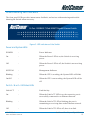
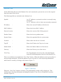
Contents
Chapter 1: Introduction .............................................................................................................................................
Gigabit Ethernet Technology ...............................................................................................................
Switching Technology .........................................................................................................................
VLAN (Virtual Local Area Network) ..................................................................................................
Features ..............................................................................................................................................
Package Contents ................................................................................................................................
4
4
5
6
7
8
Chapter 2: Installation .............................................................................................................................................. 9
Rack Mounting .................................................................................................................................... 9
Connecting Network Cable ............................................................................................................... 10
AC Power ......................................................................................................................................... 10
Chapter 3: Identifying External Components ........................................................................................................... 11
Front Panel ......................................................................................................................................... 11
Rear Panel ......................................................................................................................................... 12
Understanding LED Indicators .......................................................................................................... 13
Power and System LEDs ........................................................................................................... 13
Ports 1~16 or 1~24 Status LEDs ............................................................................................... 13
Chapter 4: Installing the Web Management Utility .................................................................................................
Discovery List ..................................................................................................................................
Monitor List ......................................................................................................................................
Device Setting ...................................................................................................................................
Toolbar .............................................................................................................................................
File TAB ....................................................................................................................................
View TAB ..................................................................................................................................
Option TAB ...............................................................................................................................
Help TAB ..................................................................................................................................
15
16
17
19
21
21
21
21
21
Chapter 5: Configuring the Switch .........................................................................................................................
Login .................................................................................................................................................
Main Menu ........................................................................................................................................
Setup Menu ................................................................................................................................
Port Settings ..........................................................................................................................
VLAN Settings (Virtual Local Area Network) ......................................................................
Trunk Setting ........................................................................................................................
Mirror Setting .......................................................................................................................
Maintenance Menu .....................................................................................................................
Device Status .......................................................................................................................
Statistic .................................................................................................................................
System Setting ......................................................................................................................
Trap Setting ..........................................................................................................................
Set Password ........................................................................................................................
Backup Setting ......................................................................................................................
Reset Setting .........................................................................................................................
Logout ........................................................................................................................................
22
22
24
25
25
26
27
28
28
28
29
30
31
32
33
33
34
NetComm 16 or 24 port Gigabit Switch
2
YML711 Rev1
www.netcomm.com.au
Appendix A: Technical Specifications .................................................................................................................. 35
General ............................................................................................................................................. 35
Performance ...................................................................................................................................... 36
Appendix B: Cable Connections ...........................................................................................................................
RJ-45 Ethernet Network ports ...........................................................................................................
1000BASE-T straight through cable ..........................................................................................
1000BASE-T crossover cable ...................................................................................................
37
37
38
39
Appendix C: Registering your NetComm Product ................................................................................................
Contact Information ..........................................................................................................................
Trade marks and Notices ..................................................................................................................
Legal & Regulatory Information Copyright Information ....................................................................
Customer Information ................................................................................................................
Warranty ....................................................................................................................................
Conditions and exclusions: ........................................................................................................
40
40
40
41
41
42
43
YML711 Rev1
www.netcomm.com.au
NetComm 16 or 24 port Gigabit Switch
3
Chapter 1: Introduction
Congratulations on your purchase of the NetComm 10/100/1000Mbps Gigabit Ethernet Web Smart
Switch, available in either 16-Port or 24-Port models. This device integrates 1000Mbps Gigabit
Ethernet, 100Mbps Fast Ethernet and 10Mbps Ethernet network capabilities in a highly flexible
package.
In this guide, the term “Switch” (first letter upper case) refers to your 16 or 24 Port 10/100/
1000Mbps Gigabit Ethernet Web Smart Switch, and “switch” (first letter lower case) refers to other
Ethernet switches.
This chapter describes the features of your new Switch and some background information about
Ethernet/Fast Ethernet/Gigabit Ethernet switching technology.
Gigabit Ethernet Technology
Gigabit Ethernet is an extension of IEEE 802.3 Ethernet utilizing the same packet structure, format,
and support for CSMA/CD protocol, full duplex, flow control, and management objects, but with a
tenfold increase in theoretical throughput over 100-Mbps Fast Ethernet and a hundredfold increase
over 10-Mbps Ethernet. Since it is compatible with all 10-Mbps and 100-Mbps Ethernet environments, Gigabit Ethernet provides a straightforward upgrade without wasting a company’s existing
investment in hardware, software and trained personnel.
The increased speed and extra bandwidth offered by Gigabit Ethernet is essential for coping with
network bottlenecks that frequently develop as computers and get faster and more applications
generate more traffic. Upgrading key components, such as your backbone and servers to Gigabit
Ethernet can greatly improve network response times as well as significantly speed up the traffic
between your subnets.
Gigabit Ethernet enables fast ethernet connections to support video conferencing, complex imaging,
and similar data-intensive applications. Likewise, since data transfers occur 10 times faster than Fast
Ethernet, servers outfitted with Gigabit Ethernet NIC’s are able to perform 10 times the number of
operations in the same amount of time.
In addition, the phenomenal bandwidth delivered by Gigabit Ethernet is the most cost-effective
method to take advantage of today’s and tomorrow’s rapidly improving switching and routing
internetworking technologies.
NetComm 16 or 24 port Gigabit Switch
4
YML711 Rev1
www.netcomm.com.au
Switching Technology
Another approach to pushing beyond the limits of standard Ethernet technology is the development
of switching technology. A switch bridges Ethernet packets at the MAC address level of the Ethernet
protocol transmitting among connected Ethernet or Fast Ethernet LAN segments.
Switching is a cost-effective way of increasing the total network capacity available to users on a local
area network. A switch increases capacity and decreases network loading by dividing a local area
network into different segments, which don’t compete with each other for network transmission
capacity.
The switch acts as a high-speed selective bridge between the individual segments. The switch,
without interfering with any other segments, automatically forwards traffic that needs to go from one
segment to another. By doing this the total network capacity is multiplied, while still maintaining the
same network cabling and adapter cards.
Switching LAN technology is a marked improvement over the previous generation of network
bridges, which were characterized by higher latencies. Routers have also been used to segment local
area networks, but the cost of a router, the setup and maintenance required make routers relatively
impractical. Today switches are an ideal solution to most kinds of local area network congestion
problems.
YML711 Rev1
www.netcomm.com.au
NetComm 16 or 24 port Gigabit Switch
5
VLAN (Virtual Local Area Network)
A VLAN is a group of end-stations that are not constrained by their physical location and can
communicate as if a common broadcast domain, a LAN. The primary reason for using a VLAN is to
reduce latency and the need for routers. Other VLAN benefits include:
Security
Security is increased with the reduction of opportunity in
eavesdropping on a broadcast network, because data will
only be switched to those confidential users within the
VLAN.
Cost Reduction
VLANs can be used to create multiple broadcast
domains, thus eliminating the need of expensive routers.
Port-based (or port-group)
Port-based is the common method of implementing a
VLAN, and is the one supplied in the Switch.
NetComm 16 or 24 port Gigabit Switch
6
YML711 Rev1
www.netcomm.com.au
Features
■ Depending on your model, either 16 or 24×10/100/1000Mbps Auto-negotiation Gigabit Ethernet
ports
■ All RJ45 ports support auto MDI/MDIX, so there is no need to use cross-over cables or an uplink port
■ Full/half duplex transfer mode for 10/100Mbps port
■ Full duplex transfer mode for Gigabit port
■ Wire speed reception and transmission
■ Store-and-Forward switching scheme capability to support rate adaptation and ensure data
integrity
■ Up to 4K unicast addresses entities per device, self-learning, and table aging
■ 272KBytes packet buffer
■ Supports IEEE 802.3x flow control for full-duplex mode ports
■ Supports port-base VLAN
■ Supports port-base QoS
■ Supports Trunking
■ Supports Port-mirroring
■ Supports Port-setting for Speed/Disable, Flow control
■ Easy configuration via WEB Browser
■ Easy setting via Web Management Utility
■ Standard 19” Rack-mount size
YML711 Rev1
www.netcomm.com.au
NetComm 16 or 24 port Gigabit Switch
7
Package Contents
Open the shipping cartons of the Switch and carefully unpacks its contents. The carton should
contain the following items:
■ One 10/100/1000Mbps Gigabit
Ethernet Web Smart Switch
(available in either 16-Port or 24Port models)
■ One AC power cord
■ Four rubber feet (for desktop usage)
■ Screws and two mounting brackets
(for rack mounting usage)
■ CD-Rom with Web Management Utility
■User’s Guide and Package Contents Note
If any of the above items are missing or damaged, please contact your local reseller for replacement.
NetComm 16 or 24 port Gigabit Switch
8
YML711 Rev1
www.netcomm.com.au
Chapter 2: Installation
The location where you install the switch stack may greatly affect its performance, therefore we
suggest you consider the following before you install your switch:
■ Install the Switch in a fairly cool and dry place. See Technical Specifications for the acceptable
temperature and humidity operating ranges.
■ Install the Switch in a site free from strong electromagnetic field generators (such as motors),
vibration, dust, and direct exposure to sunlight.
■ Leave at least 10cm of space at the front and rear of the hub for ventilation.
■ Install the Switch on a sturdy, level surface that can support its weight, or in an EIA standard-size
equipment rack. For information on rack installation, see the next section, Rack Mounting.
■ When installing the Switch on a level surface, attach the rubber feet to the bottom of each device.
The rubber feet cushion the switch and protect the switch case from scratching.
Rack Mounting
The switch can be mounted in an EIA standard-size, 19-inch rack, which can be placed in a wiring
closet with other equipment. Attach the mounting brackets to the switch’s front panel (one on each
side), and secure them with the screws provided.
Figure 1. Combine the Switch with the provided screws
Then, use screws provided with the equipment rack to mount each switch in the rack.
YML711 Rev1
www.netcomm.com.au
NetComm 16 or 24 port Gigabit Switch
9
Figure 2. Mount the Switch in the rack
Connecting Network Cable
The Switch supports 1000Mbps Gigabit Ethernet that runs in Auto-negotiation mode, 10Mbps
Ethernet or 100Mbps Fast Ethernet that runs both in half and full duplex mode, and 1000Mbps
Gigabit Ethernet that runs in full duplex mode using four pair of Category 5 Cable.
☞
Important Note:
Some Category 5 cables are only prepared with two pairs (4 wires) of
interconnection wires which are not suitable for Gigabit Ethernet over
Category 5 cables.
In order to use the full performance of this switch in Gigabit mode, please
ensure that your cabling uses four pairs (8 wires). The switch’s RJ-45 ports
are Auto-MDI and will auto negotiate between 10Mbps, 100Mbps and
1000Mbps depending on the type of cable and connection. The Switch can
auto transform to MDI-II or MDI-X, so there is no need to use cross-over
cables or an up-link port.
AC Power
The Switch uses AC power 240V AC, 50 Hz. The power switch is located at the rear of the unit
adjacent to the AC power connector and the system fan. The Switch may be turned on without
having any or all LAN segment cables connected.
NetComm 16 or 24 port Gigabit Switch
10
YML711 Rev1
www.netcomm.com.au
Chapter 3: Identifying External Components
This chapter describes the front panel, rear panel, and LED indicators of the Switch.
Front Panel
The figure below shows the front panels of the 16-Port Switch and the 24-Port Switch.
Front panel of 16-port Gigabit Ethernet Switch
Front panel of 24-port Gigabit Ethernet Switch
LED Indicator:
Comprehensive LED indicators display the status of the
switch and the network (see the following LED Indicators section).
Gigabit Ethernet Ports (1~16 or 1~24):
Depending on which model you have purchased, the
Switch has 16 or 24 Gigabit twisted pair ports, supported
auto negotiable 10/100/1000Mbps and auto MDI/MDIX
crossover detection function. This supplies true “plug
and play” capability. These ports operate in half-duplex
mode for 10/100Mbps and full- duplex mode for 10/100/
1000Mbps.
Note:
When the port is set to “Forced Mode”, the Auto MDI/MDIX feature will be
disabled.
YML711 Rev1
www.netcomm.com.au
NetComm 16 or 24 port Gigabit Switch
11
Rear Panel
Figure 4. Rear panel of the Switch
Power Switch:
The Power Switch controls the power to the unit and can
be turned on after the power cable is connected.
AC Power Connector:
This is a three-pronged connector that supports the
power cord. Plug in the female connector of the provided
power cord into this connector, and the male into a
power outlet. Supported input voltages range from 240V
AC at 50Hz.
Reset:
The Reset button will restore the unit to its factory
defaults.
Note:
Be sure that you record your Switch’s settings before pressing the Reset
button, as any changes to the default will be lost.
NetComm 16 or 24 port Gigabit Switch
12
YML711 Rev1
www.netcomm.com.au
Understanding LED Indicators
The front panel LEDs provides instant status feedback, and assists with monitoring and troubleshooting the Switch when necessary.
Figure 5. LED indicators of the Switch
Power and System LEDs
POWER
:
Power Indicator
On
:
When the Power LED is on, the Switch is receiving
power.
Off
:
When the Power LED is off, the Switch is not receiving
power.
SYSTEM
:
Management Indicator
Blinking
:
When the CPU is working, the System LED will blink.
On/Off
:
When the CPU is not working, the System LED will be
off.
Ports 1~16 or 1~24 Status LEDs
Link/ACT
:
Link/Activity
On
:
When the Link/ACT LED is on, the respective port is
successfully connected to an Ethernet network.
Blinking
:
When the Link/ACT LED is blinking, the port is
transmitting or receiving data on the Ethernet network.
Off
:
When the Link/ACT LED is off, there is no link.
YML711 Rev1
www.netcomm.com.au
NetComm 16 or 24 port Gigabit Switch
13
1000Mbps
On
:
When the 1000Mbps LED is on, the respective port is
connected to a 1000Mbps Gigabit Ethernet network.
Off
:
When the 1000Mbps LED if off, the respective port is
connected to a 10Mbps Ethernet or 100Mbps Fast
Ethernet network
On
:
When the 100Mbps LED is on, the respective port is
connected to a 100Mbps Fast Ethernet network.
Off
:
When the 100Mbps LED is off, the respective port is
connected to a 10Mbps Ethernet or 1000Mbps Gigabit
Ethernet network.
100Mbps
NetComm 16 or 24 port Gigabit Switch
14
YML711 Rev1
www.netcomm.com.au
Chapter 4: Installing the Web Management Utility
Refer to the following instructions to install the Web Management Utility and set up your Switch.
1. Insert the provided NetComm CD in the CD-ROM Drive.
2. From the Start menu on the Windows desktop, choose Run.
3. In the Run dialog box, type D:\Web Management Utility\setup.exe (where D:\ is the letter of
your CD-ROM drive) and click OK.
4. Follow the on-screen instructions to install the utility.
5. Upon completion, go to Program Files -> web_management_utility and execute the Web
Management utility. (Figure 6.)
Figure 6. Web Management Utility
The Web Management Utility is divided into four areas: Discovery List, Monitor List, Device Setting
and Toolbar function. Refer to the following sections for details on each area.
YML711 Rev1
www.netcomm.com.au
NetComm 16 or 24 port Gigabit Switch
15
Discovery List
The Discover List displays the devices available for Web management in the connected network.
By pressing the “Discovery” button, you can list all the Web Management devices in the discovery
list.
Highlight a device and press the “Add to monitor list” button, or double-click on the device listing,
to select a device in the Discovery List for monitoring in the Monitor List.
The following fields are included in the Discovery List:
MAC Address :
Shows the device MAC Address.
IP Address
Shows the current IP address of the device.
:
Protocol version:
Shows the version of the Utility protocol.
Product Name :
Shows the device product name.
System Name :
Shows the appointed device system name.
Location
:
Shows where the device is located.
Trap IP
:
Shows the IP where the Trap is to be sent.
Subnet Mask
:
Shows the Subnet Mask set of the device.
Gateway
:
Shows the Gateway set of the device.
NetComm 16 or 24 port Gigabit Switch
16
YML711 Rev1
www.netcomm.com.au
Monitor List
All the Web Smart Device in the Monitor List can be monitored; you can also receive the trap and
show the status of the device.
The following fields are included in the Monitor List:
Symbol
:
An “S” indicates a system device that is currently being
monitored.
An “X” indicates a device that is not currently connected.
IP Address
:
Shows the current IP address of the device.
MAC Address :
Shows the device MAC Address.
Protocol version:
Shows the version of the Utility protocol.
Product Name :
Shows the device product name.
System Name :
Shows the appointed device system name.
Location
:
Shows where the device is located.
Trap IP
:
Shows the IP where the Trap is to be sent.
Subnet Mask
:
Shows the Subnet Mask set of the device.
Gateway
:
Shows the Gateway set of the device.
View Trap
:
The Trap function can receive the events that happen
from the Web Management Switch in the Monitor List.
There is an indicator icon beside the “View Trap” button. When the indicator icon is green, there is
no trap being transmitted. When the indicator icon is red, there is a new trap being transmitted,
which can be viewed by clicking on the button. (Figure 7)
Figure 7. View trap
When the “View Trap” button is clicked, a Trap Information window will be displayed. This
window shows the trap information including the Symbol, Time, Device IP and the Event that
occured. (Figure 8)
YML711 Rev1
www.netcomm.com.au
NetComm 16 or 24 port Gigabit Switch
17
The
symbol represents a new trap signal record, and will disappear after you review and
click on the event record.
Figure 8. Trap Information
Note:
In order to receive Trap information, the Switch has to be configured with
Trap IP and Trap Events in the Web browser. Refer to the Trap Setting
Menu for more information.
Add Item
:
To add a device to the Monitor List manually, enter the IP
Address of the device that you want to monitor.
Delete Item
:
To delete the device in the Monitor List.
NetComm 16 or 24 port Gigabit Switch
18
YML711 Rev1
www.netcomm.com.au
Device Setting
The Device Setting panel allows you to control the configuration of your new Switch.
Configuration Setting:
The Configuration Setting allows you to set the IP
Address, Subnet Mask, Gateway, Set Trap to (Trap IP
Address), System name and Location.
Select the device in the Discovery list or Monitor List and
the click on the Configuration Setting button. The
Configuration Setting window will be displayed (refer to
Figure 9). After completing the details, type a password
and press the “Set” button to apply the changes.
Figure 9. Configuration Setting
Password Change:
The password can be changed by clicking on the
“Password Change” button. Enter the original password
and the new password and confirm it. Click on the “Set”
button to apply the change.
Figure 10. Password Change
YML711 Rev1
www.netcomm.com.au
NetComm 16 or 24 port Gigabit Switch
19
Firmware Upgrade:
To upgrade your Switch’s firmware, click on the
“Firmware Upgrade” button and enter the firmware path.
Do not turn your device off during the firmware upgrade
process.
Figure 11. Firmware Upgrade
Web Access
:
NetComm 16 or 24 port Gigabit Switch
20
Double click the device in the Monitor List or select a
device in the Monitor List and press the “Web Access”
button to access the device in your Web browser.
YML711 Rev1
www.netcomm.com.au
Toolbar
The toolbar in the Web Management Utility has four main tabs: File, View, Options and Help.
File TAB
In the “File TAB”, the following options are provided:
Monitor Save :
Allows you to save the current setting of the Monitor List
as the default. When you open the Web Management
Utility, it will automatically load this setting.
Monitor Save As:
Allows you to record the current setting of the Monitor
List in appointed filename and file path.
Monitor Load :
Allows you to manually load a setting file for the
Monitor List.
Exit
Allows you to exit the Web Management Utility.
:
View TAB
In the “View TAB”, the following options are provided:
View Log
:
Allows you to view the event log of the Web Management Utility and the device.
Clear Log
:
Allows you to clear the log.
Option TAB
In the “Option TAB”, the Refresh Time function is provided. This function helps you to define the
amount of time monitoring the device before a refresh occurs. Select 15 secs, 30 secs, 1 min, 2 min
and 5 min for the amount of time that the device will be monitored.
Help TAB
In the “Help TAB”, the About function indicates the the version of the Web Management Utility that
is currently being used.
YML711 Rev1
www.netcomm.com.au
NetComm 16 or 24 port Gigabit Switch
21
Chapter 5: Configuring the Switch
The 10/100/1000Mbps Gigabit Ethernet Web Smart Switch has a Web GUI interface for switch
configuration. The Switch can be configured through the Web Browser and a network administrator
can manage, control and monitor the switch from the local LAN. This section indicates how to
configure the Switch to enable its smart functions including:
■ Port Setting (Speed/Disable, Duplex mode, Flow Control and Port base QoS)
■ Virtual LAN Group setting (VLAN)
■ Trunking
■ Port Mirroring
■ System Setting
■ Device status and Statistic
Login
Before you configure this device, note that when the Switch is configured through an Ethernet
connection, the manager PC must be set on same the IP network. For example, when the default
network address of the default IP address of the Switch is 192.168.0.1, then the manager PC should
be set at 192.168.0.x (where x is a number between 2 and 254), and the default subnet mask is
255.255.255.0.
Open Internet Explorer 5.0 or above Web browser and enter the IP address of your switch.
Note:
The factory-default IP Address is http://192.168.0.1
Figure 12. Address
If you access the device through the Web Management Utility, you do not need to remember the IP
Address. Simply select the device shown in the Monitor List of the Web Management Utility to
display the device on the Web Browser.
When the Login screen appears, enter the default password "admin" and press Login to enter the
main configuration window.
NetComm 16 or 24 port Gigabit Switch
22
YML711 Rev1
www.netcomm.com.au
Figure 13. Login
After entering the password, the main page will display the device status.
Figure 14. Device Status
YML711 Rev1
www.netcomm.com.au
NetComm 16 or 24 port Gigabit Switch
23
Main Menu
When the main page appears, a menu lists configuration areas on the left side of the screen (Figure
15). Click on the item that you want to configure. There are eleven options: Port Settings, VLAN
Settings, Trunk Setting, Mirror Setting, Device Status, Statistic, System Settings, Trap Setting,
Password Setting, Backup Setting and Reset Setting, which are divided into the Setup and
Maintenance Menus.
Figure 15. Main menu
NetComm 16 or 24 port Gigabit Switch
24
YML711 Rev1
www.netcomm.com.au
Setup Menu
The Setup menu includes four items, including Port Settings, VLAN Settings, Trunk Settings and
Mirror Settings in Setup menu.
Port Settings
In Port Settings (Figure 16), each port’s status is displayed. Press the ID parameter to set each port’s
Speed, Flow Control, QoS priority and Link Status. When you need to renew the posted information, click on the “Refresh” button.
The Link Status on the screen will show the connection speed and duplex mode when connected or
will show “Down” to indicated that the port is disconnected.
Figure 16. Port Setting
To change the port setting, click on the ID parameter of the port. The Port Settings window will be
displayed for you to configure the Speed/Disable, Flow control and QoS setting for that Port.
Figure 17. Port Setting parameter
YML711 Rev1
www.netcomm.com.au
NetComm 16 or 24 port Gigabit Switch
25
Speed/Disable:
This field has six settings—100M Full, 100M Half, 10M
Full, 10M Half, Auto and Disable—to control speed or
port disable selections.
Flow Control:
This setting determines whether or not the Switch will be
handling flow control. Set Flow Control to Enable to
avoid data transfer overflow. Sets Flow Control to
Disable if you do not require flow control or if this is
controled by another hardware/software management
device.
When the port is set to forced mode, then the flow
control will automatically set to Disable.
QoS:
In ports that require a high priority to manage the data
transfer, QoS should be set to high. Set the QoS to
Normal for ports that do not need to have a high priority
for transferring data.
VLAN Settings (Virtual Local Area Network)
Group individual ports into a small “Virtual” network of their own to be independent of the other
ports. To add a VLAN group, press the “Add Group” button.
Figure 19. VLAN Group Settings
The new VLAN Setting configuration window will be displayed. Select the ports you wish to group
together and give them a description name. Once you want to modify the VLAN Group, check on
the ID parameter, the ID VLAN configuration window will be displayed.
NetComm 16 or 24 port Gigabit Switch
26
YML711 Rev1
www.netcomm.com.au
Figure 20. 16 Port VLAN Settings
Trunk Setting
The Trunk function enables you to cascade two devices with twice the bandwidth (maximum up to
8Gbps in full duplex mode).
There are three selections in each group of trunk setting as follow:
Group 1: Selection 1(disable), Selection 2(port 1, 2), Selection 3(port 1, 2, 3, 4).
Group 2: Selection 1(disable), Selection 2(port5, 6), Selection 3(port 5, 6, 7, 8).
Figure 21. Trunk Settings
The selected trunk setting port must correspond to the device with the same VLAN group.
YML711 Rev1
www.netcomm.com.au
NetComm 16 or 24 port Gigabit Switch
27
Mirror Setting
Port Mirroring is a method of monitoring network traffic. Port Mirroring forwards a copy of each
incoming and/or outgoing packet from one port of a network switch to another port where the
packet can be studied. It enables the manager to keep close track of switch performance and alter it if
necessary.
Configure port mirroring by assigning a source port from which to copy all packets and a sniffer port
where those packets will be sent.
The selection of the sniffer mode is as follow:
RX (receive) mode: this mode will duplicate the data that send to the source and forward to the
sniffer port.
Figure 22. Mirror Setting
Maintenance Menu
The Maintenance Menu provides you with the tools you need to ensure that your Network runs
smoothly and to control the data traffic.
Device Status
Click on “Status” to display the device status. The screen will show the System Status, Port Status,
VLAN Status, Trunk Status and Mirror Status..
Press “Refresh” when you need to renew the posted information.
NetComm 16 or 24 port Gigabit Switch
28
YML711 Rev1
www.netcomm.com.au
Statistic
The Statistic Menu screen will show the status of each port packet count.
Figure 23. Statistic
For Detail packet information, click on the ID parameter as Figure 24.
Figure 24.
YML711 Rev1
www.netcomm.com.au
NetComm 16 or 24 port Gigabit Switch
29
System Setting
The System Setting includes the System name, Location name, Login Timeout, IP Address, Subnet
Mask and Gateway. Through the Web Management Utility, you can easily recognize the device by
using the System Name and the Location Name.
The Login Timeout sets the idle time-out for the device. If there is no activity in the Web Smart
Utility, you must re-login to continue.
Insert the IP Address, Subnet Mask and Gateway for the device and click Apply.
Figure 25. System Setting
NetComm 16 or 24 port Gigabit Switch
30
YML711 Rev1
www.netcomm.com.au
Trap Setting
The Trap Setting enables the device to monitor events through the Web Management Utility, and to
set the Trap IP Address where the trap event information is to be sent.
Figure 26. Trap Setting
System Events :
Monitoring the system’s trap.
Device Bootup :
A trap is hit when booting up the system.
Illegal Login
A trap is hit when a user tries to log in using an incorrect
password, and it will record the IP address where the
incorrect login occured.
:
Twisted Pair Port Events:
Monitoring the copper port status.
Abnormal* Receive Error:
A trap where there was a receive data error in the copper
port.
Abnormal* Transmit Error:
A trap where there was a transmit data error in the copper
port.
* Abnormal is a 50 error packet count within 10 seconds.
YML711 Rev1
www.netcomm.com.au
NetComm 16 or 24 port Gigabit Switch
31
Set Password
The Set Password screen allows the network manager to secure the Switch settings. Use this screen
to change the password.
If you forget the password, you can press the “Reset” button in the rear panel of the Switch to
restore the Switch to its factory default settings.
Note:
All other settings will also be lost, including VLAN, Port Settings, etc. Refer
to Backup Setting to back up your settings before restoring the Switch to its
factory default.
Figure 27. Set Password
NetComm 16 or 24 port Gigabit Switch
32
YML711 Rev1
www.netcomm.com.au
Backup Setting
The backup setting tools help you to backup the current setting of the Switch. Once you need to
backup the setting, click on the “Backup” button to save the setting.
To restore a previous setting file to the device, identify the backup file and click on the “Restore”
button to proceed with restoring the settings of the recorded file.
Figure 28. Backup Setting
Note:
When restoring a recorded file, the current password will not be erased.
Reset Setting
The Factory Reset button helps you to reset the device back to the default setting from the factory.
Be aware that the entire configuration will be reset, the IP address of the device will be set to default
setting 192.168.0.1.
Figure 29. Reset Setting
YML711 Rev1
www.netcomm.com.au
NetComm 16 or 24 port Gigabit Switch
33
Logout
Select “Logout” to logout of the web configuration pages and return to the Login page.
Figure 30. Logout
NetComm 16 or 24 port Gigabit Switch
34
YML711 Rev1
www.netcomm.com.au
Appendix A: Technical Specifications
General
Standards
IEEE 802.3 10BASE-T Ethernet
IEEE 802.3u 100BASE-TX Fast Ethernet
IEEE 802.3ab 1000BASE-T Gigabit Ethernet
IEEE 802.3x Full Duplex Flow Control
Protocol
CSMA/CD
Data Transfer Rate
Ethernet: 10Mbps (half duplex), 20Mbps (full-duplex)
Fast Ethernet: 100Mbps (half duplex), 200Mbps (fullduplex)
Gigabit Ethernet: 2000Mbps (full-duplex)
Topology
Star
Network Cables
10BASET: 2-pair UTP Cat. 3, 4, 5; up to 100m
100BASE-TX: 2-pair UTP Cat. 5; up to 100m
1000BASE-T: 4-pair UTP Cat. 5; up to 100m
Number of Ports
16 × 10/100/1000Mbps Auto-MDIX RJ-45 ports
Physical and Environmental
AC inputs
240V AC, 50 Hz internal universal power supply
Power Consumption
25 Watts (Max)
Temperature
Operating: 0o ~ 40o C, Storage: -10o ~ 70o C
Humidity
Operating: 10% ~ 90%, Storage: 5% ~ 90%
Dimensions
440 x 210 x 44 mm (W x H x D)
EMI:
C-Tick - N367
YML711 Rev1
www.netcomm.com.au
NetComm 16 or 24 port Gigabit Switch
35
Performance
Transmits Method:
Store-and-forward
Filtering Address Table:
4K entries per device
Packet Filtering/Forwarding Rate:
10Mbps Ethernet: 14,880/pps
100Mbps Fast Ethernet: 148,800/pps
1000Mbps Gigabit Ethernet: 1,488,000/pps
MAC Address Learning:
Automatic update
Transmits Method:
Store-and-forward
RAM Buffer:
272K bytes per device
NetComm 16 or 24 port Gigabit Switch
36
YML711 Rev1
www.netcomm.com.au
Appendix B: Cable Connections
This cable information is provided for your reference only. Please ensure you only connect the
appropriate cable into the correct socket on either this product or your computer.
If you are unsure about which cable to use or which socket to connect it to, please refer to the
hardware installation section in this manual. If you are still not sure about cable connections, please
contact a professional computer technician or NetComm for further advice.
RJ-45 Ethernet Network ports
For 10BASE-T/100BASE-TX/1000BASE-T (10/100/1000BASE) connections, a twisted pair cable
with four pairs (8 wires) and RJ-45 connectors must be used.
☞
Caution: Do not plug a phone jack into any RJ-45 port. Doing so could
damage the switch. Use only twisted pair cables with RJ-45 connectors.
RJ-45 plug
attached to cable
For twisted pair cables each pair is identified by two different colours. For example, one wire might
be red, and the other red with a white stripe. An RJ-45 connector must be fitted to both ends of the
cable.
Depending on the type of connection, 10Mbps or 100Mbps, use the following Ethernet cable, as
prescribed.
10Mbps:
Use EIA/TIA-568-100-Category 3, 4 or 5 cable.
100Mbps:
Use EIA/TIA-568-100-Category 5 cable.
1000Mbps:
Use EIA/TIA-568-100-Category 5e cable.
The 1000Base-T Gigabit Ethernet standard uses all four pairs of the Cat 5e cable. Each pair is used to
transmit and receive data simultaneously, known as Dual-Duplex transmission. Basically, this is a
technique where it is possible to distinguish the direction a signal is travelling.
Cat 5e cable is an enhanced version of Cat 5 for use with 1000 Base-T networks, or for long-distance
100 Base-T links (350 m, compared with 100 m for Cat5). It must meet the EIA/TIA 568A-5
specification.
Note:
To prevent loss of signal, make sure that the length of any twisted-pair
connection does not exceed 100 meters.
YML711 Rev1
www.netcomm.com.au
NetComm 16 or 24 port Gigabit Switch
37
1000BASE-T straight through cable
For 1000BASE network connections, all four pairs are used and the cable is wired in a straightthrough configuration. The following table indicates the Pin assignments for a 10/100/1000BASE-T
RJ-45 four pair straight-through cable.
END 1
END 2
Pin
Pair
Pin
Pair
1
Pair 1+
1
Pair 1+
2
Pair 1-
2
Pair 1-
3
Pair 2+
3
Pair 2+
6
Pair 2-
6
Pair 2-
4
Pair 3+
4
Pair 3+
5
Pair 3-
5
Pair 3-
7
Pair 4+
7
Pair 4+
8
Pair 4-
8
Pair 4-
NetComm 16 or 24 port Gigabit Switch
38
YML711 Rev1
www.netcomm.com.au
1000BASE-T crossover cable
The following table indicates the Pin assignments for a 10/100/1000BASE-T RJ-45 four pair
crossover cable.
END 1
END 2
Pin
Pair
Pin
Pair
1
Pair 1+
1
Pair 2+
2
Pair 1-
2
Pair 2-
3
Pair 2+
3
Pair 1+
6
Pair 2-
6
Pair 1-
4
Pair 3+
4
Pair 4+
5
Pair 3-
5
Pair 4-
7
Pair 4+
7
Pair 3+
8
Pair 4-
8
Pair 3-
YML711 Rev1
www.netcomm.com.au
NetComm 16 or 24 port Gigabit Switch
39
Appendix C: Registering your NetComm Product
All NetComm Limited (“NetComm”) products have a standard 12 month warranty from date of
purchase against defects in manufacturing and that the products will operate in accordance with the
specifications outlined in the User Guide. However some products have an extended warranty
option (please refer to packaging). To be eligible for the extended warranty you must supply the
requested warranty information to NetComm within 30 days of the original purchase by registering
on-line via the NetComm web site at:
www.netcomm.com.au
Contact Information
If you have any technical difficulties with your product, please do not hesitate to contact
NetComm’s Customer Support Department.
Email:
[email protected]
Fax:
(+612) 9424-2010
Web:
www.netcomm.com.au
Trade marks and Notices
“NetComm” is a trade mark of NetComm. Windows® is a registered trade mark of Microsoft
Corporation. Other brand and product names are trade marks or registered trade marks of their
respective holders. Information is subject to change without notice. All rights reserved.
Please note that the images used in this document may vary slightly from those of the actual
product. Specifications are accurate at the time of the preparation of this document but are subject to
change without notice.
NetComm 16 or 24 port Gigabit Switch
40
YML711 Rev1
www.netcomm.com.au
Legal & Regulatory Information Copyright Information
This manual is a copyright protected work. Apart from any fair dealing exceptions for the purposes
of private study, research, criticism or review, as permitted under the Australian Copyright Act 1968
(Cth), no part of this manual may be reproduced, stored in a retrieval system or communicated,
published, performed or adapted in any form, by any means, be it electronic, mechanical, recording
or otherwise, without the prior written permission of NetComm. NetComm accepts no liability or
responsibility, for consequences arising from the use of this product or manual.
NetComm reserves the right to change the specifications and operating details of this product and
manual without notice and does not warrant that any changes to the specifications or operating
details of the product will meet the requirements of the customer or will be able to interoperate,
remain compatible or coexist with any other hardware or software the customer uses.
Registration of warranties, either via the NetComm web site or via post is subject to NetComm’s
privacy policy and procedures. Copies of NetComm’s privacy policy and procedures can be
obtained from www.netcomm.com.au.
Customer Information
ACA (Australian Communications Authority) requires you to be aware of the following information
and warnings in relation to the purchased product:“
(I) This unit shall be connected to the Telecommunication Network through a line cord which meets
the requirements of the ACA TSOOS Standard.“
(2) This equipment has been tested and found to comply with the Standards for C-Tick and or ATick as set by the ACA. These standards are designed to provide reasonable protection against
harmful interference in a residential installation. This equipment generates, uses, and can radiate
radio noise and, if not installed and used in accordance with the instructions detailed within this
manual, may cause interference to radio communications. However, there is no guarantee that
interference will not occur with the installation of this product in your home or office. If this
equipment does cause some degree of interference to radio or television reception, which can be
determined by turning the equipment off and on, we encourage the user to try to correct the
interference by one or more of the following measures:
•
•
•
•
Change the direction or relocate the receiving antenna.
Increase the separation between this equipment and the receiver.
Connect the equipment to an alternate power outlet on a different power circuit from
that to which the receiver/TV is connected.
Consult an experienced radio/TV technician for help.
(3) The power supply that is provided with this unit is only intended for use with this product. Do
not use this power supply with any other product or do not use any other power supply that is
not approved for use with this product by NetComm. Failure to do so may cause damage to this
product, fire or result in personal injury.
YML711 Rev1
www.netcomm.com.au
NetComm 16 or 24 port Gigabit Switch
41
Warranty
Where the Customer (you) is a consumer as defined by any relevant law such as the Trade Practices
Act 1974 (Commonwealth) and similar State laws, certain conditions and warranties (“the consumer
warranties”) cannot be excluded, restricted or modified. You then have the benefit of both the
consumer warranties and any other warranty that may be provided by the Company or by the
manufacturer of the goods. To the extent permitted by Law, all implied warranties and conditions
are excluded.
All NetComm products have a standard 12 months warranty from date of purchase. However some
products have an extended warranty option (refer to packaging). To be eligible for the extended
warranty you must supply the requested warranty information to NetComm within 30 days of the
original purchase by registering on-line via the NetComm web site at www.netcomm.com.au.
To the extent permitted by the consumer warranties, in relation to your product and any other
materials provided with the product (“the Goods”) the liability of NetComm under the Relevant Acts
is limited at the option of NetComm to:
■ replace the Goods; or
■ repair of the Goods; or
■ pay for the cost to replace the Goods; or
■ pay for the cost to repair the Goods.
NetComm 16 or 24 port Gigabit Switch
42
YML711 Rev1
www.netcomm.com.au
Conditions and exclusions:
The warranty is granted on the following conditions:
1. This warranty extends to the original retail Customer (you) and is not transferable;
2. This warranty does not apply to software programs, batteries, power supplies, cables or other
accessories supplied in or with the product;
3. You must comply with all of the terms of any relevant agreement with NetComm and any other
reasonable requirements of NetComm including producing such evidence of purchase as
NetComm may require;
4. The cost of transporting the product under a claim based on this warranty to and from
NetComm’s nominated premises is your responsibility; and
5. NetComm does not have any liability or responsibility under this warranty where any cost, loss,
injury or damage of any kind, whether direct, indirect, consequential, incidental or otherwise
arises out of events beyond NetComm’s reasonable control. This includes but is not limited to:
acts of God, war, riot, embargoes, acts of civil or military authorities, fire, floods, electricity
outages, lightning, power surges, or shortages of materials or labour.
6. You are responsible for the security of your computer and network at all times. Security features
may be disabled within the factory default settings. NetComm recommends that you enable
these features to enhance your security.
YML711 Rev1
www.netcomm.com.au
NetComm 16 or 24 port Gigabit Switch
43