1
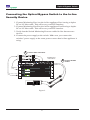
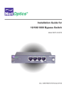
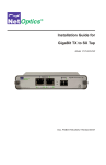
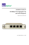
Installation Guide for
Optical Bypass Switch
Models N-IDP-POBPSX-001, N-IDP-POBPLX-002
Doc. IGNET-N-IDP-POBPSX-001/LX-002 Revised 09/05
Optical Bypass Switch
Table of Contents
Introduction. . . . . . . . . . . . . . . . . . . . . . . . . . . . . . . . . . . . . . . . . . . . . . . . . . . . . . 1
Key Features. . . . . . . . . . . . . . . . . . . . . . . . . . . . . . . . . . . . . . . . . . . . . . . . . . . . . 1
Product Diagram. . . . . . . . . . . . . . . . . . . . . . . . . . . . . . . . . . . . . . . . . . . . . . . . . . 3
Power Loss Bypass. . . . . . . . . . . . . . . . . . . . . . . . . . . . . . . . . . . . . . . . . . . . . . . . 4
Connecting the Optical Bypass Switch to the Network. . . . . . . . . . . . . . . . . . . . 5
Connecting the Optical Bypass Switch to the IPS . . . . . . . . . . . . . . . . . . . . . . . . 6
Specifications . . . . . . . . . . . . . . . . . . . . . . . . . . . . . . . . . . . . . . . . . . . . . . . . . . . . 7
Warranty. . . . . . . . . . . . . . . . . . . . . . . . . . . . . . . . . . . . . . . . . . . . . . . . . . . . . . . . 8
Optical Bypass Switch
PLEASE READ THESE LEGAL NOTICES CAREFULLY.
By using a Net Optics Optical Bypass Switch you agree to the terms and conditions of usage set forth
by Net Optics, Inc..
.
No licenses, express or implied, are granted with respect to any of the technology described in this
manual. Net Optics retains all intellectual property rights associated with the technology described in
this manual. This manual is intended to assist with installing Net Optics products into your network.
Trademarks and Copyrights
© 2005 by Net Optics, Inc. Net Optics® is a registered trademark of Net Optics, Inc. Additional
company and product names may be trademarks or registered trademarks of the individual companies
and are respectfully acknowledged.
Additional Information
Net Optics, Inc. reserves the right to make changes in specifications and other information contained
in this document without prior notice. Every effort has been made to ensure that the information in
this document is accurate. Net Optics is not responsible for typographical errors.
Optical Bypass Switch
Introduction
Net Optics Optical Bypass Switches provide a permanent and trouble-free
access port for in-line network security and monitoring devices. The Optical Bypass Switch automatically switches network traffic through added IDP
devices or bypasses devices that are about to be removed. Prevent link failure
when attached IDP devices lose power by powering the Bypass Switch and
in-line device from the same power source. Uninterrupted traffic
The Optical Bypass Switch supports fail-open monitoring with any fiber IDP
device when it shares the same power source as the IDP. While the Optical
Bypass Switch is receiving power, it diverts network traffic to attached IDP. In
this state, all in-line traffic is routed directly to the IDP connected to the Optical Bypass Switch. When the Optical Bypass Switch loses power, in-line traffic continues to flow
through the network link, but is no longer routed through the device. This allows the network devices to be removed and replaced without network downtime. Once power is restored to the Optical Bypass Switch, network traffic is
seamlessly diverted to the IDP, allowing it to resume its critical functions.
Simply Plug It In
Each Bypass Switch includes all the cables and power supplies you need to
quickly connect to an IDP. Three quick steps is all it takes to establish a secure
connection point for inline devices.
Key Features
Passive, Secure Technology
• Fail-open monitoring with any GigaBit fiber in-line appliance at speeds of
1000 Mbps
• Increased reliability on critical network links
• High-speed optical switching with minimal insertion loss
Optical Bypass Switch
Key Features (continued)
Ease of Use
•
•
•
•
LED indicator shows power status
Front-mounted connectors support easy installation and operation
Cables included for plug-and-play deployment
Silk-screened application diagram illustrates all connections for easy deployment
• Optional 19-inch rack frames holds two Bypass Switches
• Tested and compatible with all major manufacturers’ monitoring devices,
including protocol analyzers, probes, and intrusion detection/prevention
systems
Support
• Net Optics offers free technical support throughout the lifetime of your
purchase. Our technical support team is available from 8 am to 5 pm Pacific
Time, Monday through Friday at +1 (408) 737-7777 and via email at [email protected]. FAQs are also available on Net Optics website at
www.netoptics.com.
Optical Bypass Switch
Product Diagram
Optical Bypass Switch
®
A
A
B
OUT
IN
OUT
IN
OUT
IN
Network
GigaBit
96470
B
Monitor
OUT
IN
www.netoptics.com
Network Ports A & B
Monitor Ports A & B
Figure 1. Front View Panel
Silk Screen Diagram
Power Connector
®
®
x
T
x
R
A
x
T
x
R
B
x
T
x
R
Network A
A
x
T
x
B
R
Network B
Monitor A
Monitor B
Figure 2.
Optical Bypass Switch
Power Loss Bypass
The Optical Bypass Switch protects link integrity when the in-line appliance
loses power. When the Bypass Switch is receiving power it is in Bypass
Disabled (OFF ) mode. In Bypass Disabled mode the switch sends network
traffic through the connnected device.
Bypass Disabled Mode
1 When the Bypass Switch is in Bypass Disabled
mode, all in-line traffic is routed through the
Juniper IDP appliance.
Bypass Switch
Internet
®
Router
Firewall
A
B
A
B
Switch
Switch
www.netoptics.com
2 The Bypass switch is
receiving power from
the DC power supply.
Juniper Networks
IDP-1100
Figure 3.
When power to the Bypass switch fails, it enters Bypass Enabled (ON) mode
and network traffic bypasses the connected device until power to the switch is
restored.
Bypass Enabled Mode
1 When
the Bypass Switch is in Bypass Enabled
mode, all in-line traffic continues to flow on the
network link without being directed through the
Juniper IDP appliance
Bypass Switch
Internet
®
Router
Firewall
Switch
A
B
A
B
www.netoptics.com
Because in-line traffic is no longer 3
flowing through the IDP, the appliance
may be removed and replaced without
downtime.
Switch
2 When there is no power to
the Bypass switch, it enters
Bypass Enabled mode.
Juniper Networks
IDP-1100
Figure 4.
Optical Bypass Switch
Unpacking and Inspection
Unpack the Optical Bypass Switch, power supply, and cables provided. Each
Optical Bypass Switch is delivered with the following:
For models N-IDP-POBPSX-001, N-IDP-POBPLX-002:
• 1 DC power supply
• 2 Duplex SC-SC fiber cables
• 2 Duplex SC-LC fiber cables
• 1 Manual
If any component is missing or damaged, contact Net Optics Customer
Service immediately.
Connecting the Optical Bypass Switch to the
Network
1.Connect Network Port A to the appropriate switch, server or router device
using a duplex SC fiber cable. This acts as your DCE interface.
2.Connect Network Port B to the appropriate switch, server or router device
using a duplex SC fiber cable. This acts as your DTE interface.
3.Verify that the Bypass Switch Network Ports are cabled in-line between two
devices.
Optical Bypass Switch
Connecting the Optical Bypass Switch to the In-line
Security Device
1.Connect Monitoring Port A to the in-line appliance Port A using a duplex
SC-to-LC fiber cable. This will act as your DCE Interface.
2.Connect Monitoring Port B to the in-line appliance Port B using a duplex
SC-to-LC fiber cable. This will act as your DTE interface.
3.Verify that the Switch Monitoring Ports are cabled in-line between two
devices.
4.Connect the power supply to the switch. Make sure you connect the
switches’ power supply to the same power sources that in-line appliance is
using.
1
Connect Fiber In-Line Ports
Tx
Rx
DTE
Tx
Rx
DCE
Rx
Tx
Rack-Mount Frame
Holds 2 Switches
Rx
Tx
A
®
Switch
A
®
B
S
M
To
switch, server,
or router
(DCE)
2
A BB
A
S
M
S
M
Network
Monitor
A BB
A
S
M
IS
C
Y
S
B
S
M
S
M
Network
B
O
Monitor
C
A
x
1
2
a
B
0
1
/
X
T
se
8
1
x
8
M
E
T
S
B
F
x
1
x
2
x
3
x
4
x
5
6
x
x
7
i
IF
D
A
rD
e
b
x
8
A
S
x
9
x
0
1
x
1
B
1
a
B
0
1
T
se
x
2
x
3
1
x
4
1
5
1
x1
x
6
x
7
1
x
x
3
x
4
x
5
6
x
x
9
1
x
0
2
1
2
x
x
2
x
3
2
x
4
2
x
x
3
x
4
x
5
6
x
x
0
2
1
2
x
x
2
x
3
2
x
4
2
x
7
x
8
x
7
x
8
Æ
IS
C
To
switch, server, or router
(DTE)
Y
O
C
S
B
O
S
M
C
A
x
1
2
a
B
0
1
/
X
T
se
8
1
x
8
x
9
1
Y
S
B
x
1
x
2
x
3
x
4
x
5
6
x
F
i
IF
D
x
7
x
8
A
rD
e
b
A
S
x
9
x
0
1
x
1
B
1
x
2
x
3
1
x
4
1
5
1
x1
x
6
x
7
1
Rx
Tx
Rx
Tx
E
DC
U
T
P
A
T
M
A
T
M
D
C
E
D
T
E
T
H
I
C
K
N
E
T
T
H
I
N
N
E
T
C
O
N
S
O
L
E
S
W
1
R
E
M
O
T
E
Tx
Rx
IPS
Tx
Rx
Figure 5.
E
DT
Connect SC Fiber
Cables
Optical Bypass Switch
Specifications
Splitter Specifications:
Fiber Type: Multimode: Corning 62.5/125µm, wavelength, 850nm
Insertion Loss: Network Port: ≤ 1.25 dB
Monitor Port: ≤ 1.25 dB
Fiber Type: Singlemode: Corning 8.5/125µm, wavelength, 1300nm
Insertion Loss: Network Port: ≤ 1.25 dB
Monitor Port: ≤ 1.25 dB
Note: There is no insertion loss when the switch is not receiving power
and is in Bypass Disabled mode.
Operating Specifications:
Operating Temperature: 5˚C to 40˚C
Storage Temperature: -10˚C to 70˚C
Relative Humidity: 10% min, 95% max, non-condensing
Mechanical Specifications:
Power Supply: Input Power: 100-250V, 0.5A, 47-63Hz
Output Power: 5V, 2.4A
Dimensions: 1.125” high x 6.0” deep x 6.5” wide
Connectors:
(2) Duplex SC connectors (monitoring ports)
(2) Duplex SC connectors (network ports)
Optical Bypass Switch
Limitations on Warranty and Liability
Net Optics offers a limited warranty for all its products. IN NO EVENT SHALL NET OPTICS, INC. BE LIABLE FOR ANY DAMAGES INCURRED BY THE USE OF THE PRODUCTS (INCLUDING BOTH HARDWARE AND SOFTWARE) DESCRIBED IN THIS MANUAL, OR BY ANY
DEFECT OR INACCURACY IN THIS MANUAL ITSELF. THIS INCLUDES BUT IS NOT LIMITED TO LOST PROFITS, LOST SAVINGS, AND ANY INCIDENTAL OR CONSEQUENTIAL
DAMAGES ARISING FROM THE USE OR INABILITY TO USE THIS PRODUCT, even if Net
Optics has been advised of the possibility of such damages. Some states do not allow the exclusion
or limitation of implied warranties or liability for incidental or consequential damages, so the above
limitation or exclusion may not apply to you.
Net Optics, Inc. warrants this Optical Bypass Switch to be in good working order for a period of ONE
YEAR from the date of purchase from Net Optics or an authorized Net Optics reseller.
Should the unit fail anytime during the said ONE YEAR period, Net Optics will, at its discretion,
repair or replace the product. This warranty is limited to defects in workmanship and materials and
does not cover damage from accident, disaster, misuse, abuse or unauthorized modifications.
If you have a problem and require service, please call the number listed at the end of this section and
speak with our technical service personnel. They may provide you with an RMA number, which must
accompany any returned product. Return the product in its original shipping container (or equivalent)
insured and with proof of purchase.
Additional Information
Net Optics, Inc. reserves the right to make changes in specifications and other information contained
in this document without prior notice. Every effort has been made to ensure that the information in
this document is accurate. Net Optics is not responsible for typographical errors.
THE WARRANTY AND REMEDIES SET FORTH ABOVE ARE EXCLUSIVE AND IN LIEU OF
ALL OTHERS, EXPRESS OR IMPLIED. No Net Optics reseller, agent, or employee is authorized
to make any modification, extension, or addition to this warranty.
Net Optics is always open to any comments or suggestions you may have about its products and/or
this manual.
Send correspondence to.
Net Optics, Inc..
1130 Mountain View Alviso Road.
Sunnyvale, CA 94089-2237 USA.
Telephone: +1 (408) 737-7777.
Fax: +1 (408) 745-7719.
Email: [email protected]/Internet: www.netoptics.com
All Rights Reserved. Printed in the U.S.A. No part of this publication may be reproduced, transmitted, transcribed, stored in a retrieval system, or translated into any language or computer language,
in any form, by any means, without prior written consent of Net Optics, Inc., with the following
exceptions: Any person is authorized to store documentation on a single computer for personal use
only and that the documentation contains Net Optics’ copyright notice.
www.netoptics.com
© 2005 by Net Optics, Inc. All Rights Reserved.