1
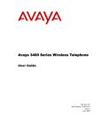
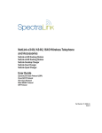
Mobile Handset 120 and
Desktop Charger/
Gang Charger
User Guide
NEC Business Solutions Ltd.
Doc. No: NEC-9121
Revision 2
July, 2005
Liability Disclaimer
PLEASE NOTE:
It is recommended that standard acceptance procedures be followed
prior to operating this equipment in proximity of life-support systems.
To minimize risk of interference, pacemaker users should not carry the
Wireless Telephone next to the pacemaker.
Earpiece may retain magnetic objects.
Operation of the Wireless Telephone may produce an audible noise
noticeable to hearing aid users. It is recommended that a hearing aid
compatible headset be used by hearing aid users.
WARNING
Changes or modifications to this equipment not approved by NEC
Business Solutions Ltd. may cause this equipment to not comply
with part 15 of the FCC rules and void the user's authority to
operate this equipment.
NEC Business Solutions, Ltd. products contain no user-serviceable
parts inside. Refer servicing to qualified service personnel.
WARNING
NOTE CONCERNING THE WIRELESS TELEPHONES:
This device complies with part 15 of the FCC Rules. Operation is
subject to the following two conditions: (1) This device may not cause
harmful interference, and (2) this device must accept any interference
received, including interference that may cause undesired operation.
RADIO FREQUENCY (RF) INFORMATION:
This equipment has been tested and found to comply with the limits
for a Class B digital device, pursuant to Part 15 of the FCC Rules.
These limits are designed to provide reasonable protection against
harmful interference in a residential installation. This equipment
generates, uses and can radiate radio frequency energy and, if not
installed and used in accordance with the instructions, may cause
harmful interference to radio communications. However, there is no
guarantee that interference will not occur in a particular installation. If
this equipment does cause harmful interference to radio or television
reception, which can be determined by turning the equipment off and
on, the user is encouraged to try to correct the interference by one or
more of the following measures:
• Reorient or relocate the receiving antenna.
• Increase the separation between the equipment and receiver.
• Connect the equipment into an outlet on a circuit different from
that to which the receiver is connected.
• Consult the dealer or an experienced radio/TV technician for help.
OPERATIONAL WARNINGS:
For Vehicles Equipped with an Air Bag: Do not place a
portable radio product in the area over the air bag or in the air bag
deployment area. An air bag inflates with great force. If a portable
radio is placed in the air bag deployment area and the air bag inflates,
the radio product may be propelled with great force and cause serious
injury to occupants of the vehicle.
Potentially Explosive Atmospheres: Turn off your radio
product, prior to entering any area with a potentially explosive
atmosphere, unless it is a radio product type especially qualified for
use in such areas (for example, Factory Mutual Approved). Do not
remove, install, or charge batteries in such areas. Sparks in a
potentially explosive atmosphere can cause an explosion or fire
resulting in bodily injury or even death.
CAUTION
The areas with potentially explosive atmospheres referred to
above include fueling areas such as below decks on boats, fuel or
chemical transfer or storage facilities, areas where the air contains
chemicals or particles, such as grain, dust or metal powders, and
any other area where you would normally be advised to turn off
your vehicle engine. Areas with potentially explosive atmospheres
are often but not always posted.
Batteries: All batteries can cause property damage and/or bodily
injury, such as burns if a conductive material such as jewelry, keys, or
beaded chains touches exposed terminals. The conductive material
may complete an electrical circuit (short circuit) and become quite hot.
Exercise care in handling any charged battery, particularly when
placing it inside a pocket, purse, or other container with metal objects.
Cleaning and Drying Considerations: Using a leather carry
case may help protect the surfaces and help prevent liquids (e.g., rain)
from entering into the interior of the radio product. This product is not
waterproof, and exposing the unit to liquids may result in permanent
damage to the unit.
If your Wireless Telephone interior gets wet, then do not try to
accelerate drying with the use of an oven or a dryer as this will
damage the Wireless Telephone and void the warranty. Instead, do the
following: 1. Immediately power off the Wireless Telephone. 2.
Remove Battery Pack from Wireless Telephone. 3. Shake excess liquid
from Wireless Telephone. 4. Place the Wireless Telephone and Battery
Pack in an area that is at room temperature and has good airflow. 5.
Let the Wireless Telephone and Battery Pack dry for 72 hours before
reconnecting the Battery Pack and/or powering on the Wireless
Telephone. If the Wireless Telephone does not work after following the
steps listed above, contact your dealer for servicing information.
Electro Magnetic Interference/Compatibility:
Nearly every electronic device is susceptible to electromagnetic
interference (EMI) if inadequately shielded, designed or otherwise
configured for electromagnetic compatibility.
NOTE
Facilities
To avoid electromagnetic interference and/or compatibility conflicts,
turn off your radio product in any facility where posted notices instruct
you to do so. Hospitals or health care facilities may be using
equipment that is sensitive to external RF energy.
Medical Devices
Pacemakers: The Health Industry Manufacturers Association
recommends that a minimum separation of 6 inches (15 cm) be
maintained between a handheld wireless radio product and a
pacemaker. These recommendations are consistent with the
independent research by, and recommendations of, Wireless
Technology Research. Persons with pacemakers should:
• ALWAYS keep the radio product more than 6 inches (15 cm) from
their pacemaker when the radio product is turned ON.
• Not carry the radio product in a breast pocket.
• Use the ear opposite the pacemaker to minimize the potential for
interference.
• Turn the radio product OFF immediately if you have any reason to
suspect that interference is taking place.
Hearing Aids: Some digital wireless radio products may interfere
with some hearing aids. In the event of such interference, you may
want to consult your hearing aid manufacturer to discuss alternatives.
Other Medical Devices: If you use any other personal medical
device, consult the manufacturer of your device to determine if it is
adequately shielded from external RF energy. Your physician may be
able to assist you in obtaining this information.
Use While Driving
Check the laws and regulations on the use of radio products in the
area where you drive. Always obey them. When using the radio
product while driving, please:
• Give full attention to driving and to the road.
• Use hands-free operation, if available.
• Pull off the road and park before making or answering a call if
driving conditions so require.
INTERNATIONAL CERTIFICATIONS:
Australia
Brazil
NEED NEC BARCODE
Canada
European Union
2128-K1374
Switzerland
Switzerland
Japan
Mexico
New Zealand
Singapore
United States
United States
Z233
IDA
IEC 60950
Part 15, part 68
MH110 Wireless Telephones
SPECIFIC ABSORPTION RATE (SAR) INFORMATION:
Your wireless handheld portable telephone is a low power radio
transmitter and receiver. When it is ON, it receives and also sends out
radio frequency (RF) signals. In August 1996, the Federal
Communications Commissions (FCC) adopted RF exposure guidelines
with safety levels for hand-held wireless phones. Those guidelines are
consistent with the safety standards previously set by both U.S. and
international standards bodies:
• ANSI C95.1 (1992) American National Standards Institute
• NCRP - Report 86 (1986) National Council on Radiation Protection
and Measurements
• ICNIRP (1996) International Commission on Non-Ionizing
Radiation Protection;
• DHWC - Safety Code 6 Department of Health and Welfare Canada
Those standards were developed by independent scientific
organizations through periodic and thorough evaluation of scientific
studies. The standards include a substantial safety margin designed to
assure the safety of all persons, regardless of age and health. The
exposure standard for wireless mobile phones employs a unit of
measurement known as the Specific Absorption Rate, or SAR. The SAR
limit set by the FCC is 1.6W/kg.
NOTE
In the United States and Canada, the SAR limit for mobile phones
used by the public is 1.6 watts/kg (W/kg) averaged over one gram
of tissue. The standard incorporates a substantial margin of safety
to give additional protection for the public and to account for any
variations in measurements.
Tests for SAR are conducted using standard operating positions
specified by the FCC with the phone transmitting at its highest certified
power level in all tested frequency bands. Although the SAR is
determined at the highest certified power level, the actual SAR level of
the phone while operating can be well below the maximum value. This
is because the phone is designed to operate at multiple power levels so
as to use only the power required to reach the network. In general,
the closer you are to a wireless base station antenna, the lower the
power output. Before a phone model is available for sale to the public,
it must be tested and certified to the FCC that it does not exceed the
limit established by the government-adopted requirement for safe
exposure. The tests are performed in positions and locations (e.g., at
the ear and worn on the body) as required by the FCC for each model.
While there may be differences between the SAR levels of various
phones and at various positions, they all meet the government
requirement for safe exposure. The FCC has granted an Equipment
Authorization for this model phone with all reported SAR levels
evaluated as in compliance with the FCC RF emission guidelines.
SAR information on this model phone is on file with the FCC and can
be found under the Display Grant section of http://www.fcc.gov/oet/
fccid after searching on FCC ID IYGRNP2400. Additional information on
Specific Absorption Rates (SAR) can be found on the Cellular
Telecommunications Industry Association (CTIA) web-site at http://
www.wow-com.com.
The only authorized headsets that may be utilized with the SNP2400
are those obtainable from SpectraLink or it’s reseller partners.
The measured SAR of the SNP2400 Wireless Telephone is
0.61W/kG @ 2462 MHz (head) 0.0379W/kG @ 2412 MHz (body).
Phone Operation Normal Position: Hold the phone as you would
any other telephone, with the earpiece to your ear and speak into
the microphone. The internal antenna is then positioned properly.
CAUTION
MH120
SPECIFIC ABSORPTION RATE (SAR) INFORMATION:
Your wireless handheld portable telephone is a low power radio
transmitter and receiver. When it is ON, it receives and also sends out
radio frequency (RF) signals. In August 1996, the Federal
Communications Commissions (FCC) adopted RF exposure guidelines
with safety levels for hand-held wireless phones. Those guidelines are
consistent with the safety standards previously set by both U.S. and
international standards bodies:
• ANSI C95.1 (1992) American National Standards Institute
• NCRP - Report 86 (1986) National Council on Radiation Protection
and Measurements
• ICNIRP (1996) International Commission on Non-Ionizing
Radiation Protection;
• DHWC - Safety Code 6 Department of Health and Welfare Canada
Those standards were developed by independent scientific
organizations through periodic and thorough evaluation of scientific
studies. The standards include a substantial safety margin designed to
assure the safety of all persons, regardless of age and health. The
exposure standard for wireless mobile phones employs a unit of
measurement known as the Specific Absorption Rate, or SAR. The SAR
limit set by the FCC is 1.6W/kg. T
NOTE
In the United States and Canada, the SAR limit for mobile phones
used by the public is 1.6 watts/kg (W/kg) averaged over one gram
of tissue. The standard incorporates a substantial margin of safety
to give additional protection for the public and to account for any
variations in measurements.
Tests for SAR are conducted using standard operating positions
specified by the FCC with the phone transmitting at its highest certified
power level in all tested frequency bands. Although the SAR is
determined at the highest certified power level, the actual SAR level of
the phone while operating can be well below the maximum value. This
is because the phone is designed to operate at multiple power levels so
as to use only the power required to reach the network. In general,
the closer you are to a wireless base station antenna, the lower the
power output. Before a phone model is available for sale to the public,
it must be tested and certified to the FCC that it does not exceed the
limit established by the government-adopted requirement for safe
exposure. The tests are performed in positions and locations (e.g., at
the ear and worn on the body) as required by the FCC for each model.
While there may be differences between the SAR levels of various
phones and at various positions, they all meet the government
requirement for safe exposure. The FCC has granted an Equipment
Authorization for this model phone with all reported SAR levels
evaluated as in compliance with the FCC RF emission guidelines. SAR
information on this model phone is on file with the FCC and can be
found under the Display Grant section of http://www.fcc.gov/oet/fccid
after searching on FCC ID IYGRNP2400. Additional information on
Specific Absorption Rates (SAR) can be found on the Cellular
Telecommunications Industry Association (CTIA) web-site at http://
www.wow-com.com.
The only authorized headsets that may be utilized with the RNP2400
are those obtainable from SpectraLink or it’s reseller partners.
The measured SAR of the RNP2400 Wireless Telephone is
0.166W/kG @ 2462 MHz (head) 0.0162W/kG @ 2412 MHz (body).
Phone Operation Normal Position: Hold the phone as you would
any other telephone, with the earpiece to your ear and speak into
the microphone. The internal antenna is then positioned properly.
CAUTION
i
Contents
Introduction
1-1
Using this Guide . . . . . . . . . . . . . . . . . . . . . . . . . . . . . . . . . . . . . . . . . . . . . . . . 1-1
How this Guide is Organized . . . . . . . . . . . . . . . . . . . . . . . . . . . . . . . . . . . . . . 1-1
Document Conventions . . . . . . . . . . . . . . . . . . . . . . . . . . . . . . . . . . . . . . . . . . . 1-2
MH120 Wireless Telephone
2-1
Turning the Wireless Telephone On or Off . . . . . . . . . . . . . . . . . . . . . . . . . . . . 2-2
Making a Call. . . . . . . . . . . . . . . . . . . . . . . . . . . . . . . . . . . . . . . . . . . . . . . . . . . 2-2
Answering A Call . . . . . . . . . . . . . . . . . . . . . . . . . . . . . . . . . . . . . . . . . . . . . . . . 2-2
Activating System Features. . . . . . . . . . . . . . . . . . . . . . . . . . . . . . . . . . . . . . . . 2-3
Using the Softkeys . . . . . . . . . . . . . . . . . . . . . . . . . . . . . . . . . . . . . . . . . . . . . . 2-5
Using Push to Talk (PTT) . . . . . . . . . . . . . . . . . . . . . . . . . . . . . . . . . . . . . . . . . 2-6
Utilizing Status Indicators . . . . . . . . . . . . . . . . . . . . . . . . . . . . . . . . . . . . . . . . . 2-9
Using Wireless Telephone Headsets. . . . . . . . . . . . . . . . . . . . . . . . . . . . . . . . 2-10
Setting User Preferences . . . . . . . . . . . . . . . . . . . . . . . . . . . . . . . . . . . . . . . . 2-10
Configuring the User Option Menu . . . . . . . . . . . . . . . . . . . . . . . . . . . . . . . . . 2-11
Working with Battery Packs. . . . . . . . . . . . . . . . . . . . . . . . . . . . . . . . . . . . . . . 2-12
Removing and Replacing Battery Packs . . . . . . . . . . . . . . . . . . . . . . . . . . . . . 2-12
Mobile Handset 120 and Desktop Charger/Gang Charger User Guide - Revision 1
ii
Contents
Using the MH120 Desktop and Gang Chargers
3-1
The MH120 Desktop Charger . . . . . . . . . . . . . . . . . . . . . . . . . . . . . . . . . . . . . . 3-1
Using the MH120 Desktop Charger . . . . . . . . . . . . . . . . . . . . . . . . . . . . . . . . . 3-2
MH120 Gang Charger . . . . . . . . . . . . . . . . . . . . . . . . . . . . . . . . . . . . . . . . . . . . 3-3
Using the Gang Charger . . . . . . . . . . . . . . . . . . . . . . . . . . . . . . . . . . . . . . . . . . 3-3
Cleaning the Chargers . . . . . . . . . . . . . . . . . . . . . . . . . . . . . . . . . . . . . . . . . . . 3-4
Care of the Wireless Telephone and Chargers
4-1
Precautions . . . . . . . . . . . . . . . . . . . . . . . . . . . . . . . . . . . . . . . . . . . . . . . . . . . . 4-1
Cleaning tips . . . . . . . . . . . . . . . . . . . . . . . . . . . . . . . . . . . . . . . . . . . . . . . . . . . 4-1
Usage Tips . . . . . . . . . . . . . . . . . . . . . . . . . . . . . . . . . . . . . . . . . . . . . . . . . . . . 4-2
Mobile Handset 120 and Desktop Charger/Gang Charger User Guide - Revision 1
iii
Figures
Figure
2-1
2-2
3-1
3-2
Title
Page
MH120 Wireless Telephone . . . . . . . . . . . . . . . . . . . . . . . . . . . . . . . . . . 2-1
MH120 Wireless Telephone—display area highlighted . . . . . . . . . . . . . . 2-5
NEC Business Solutions Ltd. MH120 Desktop Charger. . . . . . . . . . . . . . 3-1
NEC Business Solutions Ltd. Gang Charger . . . . . . . . . . . . . . . . . . . . . . 3-3
Mobile Handset 120 and Desktop Charger/Gang Charger User Guide - Revision 1
iv
Figures
Mobile Handset 120 and Desktop Charger/Gang Charger User Guide - Revision 1
v
Tables
Table
1-1
2-1
2-2
2-3
2-4
2-5
3-1
Title
Page
Document Conventions . . . . . . . . . . . . . . . . . . . . . . . . . . . . . . . . . . . . . 1-2
Call Answering Features . . . . . . . . . . . . . . . . . . . . . . . . . . . . . . . . . . . . 2-3
Programmed features . . . . . . . . . . . . . . . . . . . . . . . . . . . . . . . . . . . . . . . 2-4
MH120 Status Indicators . . . . . . . . . . . . . . . . . . . . . . . . . . . . . . . . . . . . 2-9
User Preferences Navigation Tools . . . . . . . . . . . . . . . . . . . . . . . . . . . 2-10
User Option Menu Commands . . . . . . . . . . . . . . . . . . . . . . . . . . . . . . . 2-11
MH120 Desktop Charger LED indicator lights . . . . . . . . . . . . . . . . . . . . 3-2
Mobile Handset 120 and Desktop Charger/Gang Charger User Guide - Revision 1
vi
Tables
Mobile Handset 120 and Desktop Charger/Gang Charger User Guide - Revision 1
1-1
1
Introduction
Welcome to the MH120 and Desktop Charger/Gang Charger User Guide.
This guide provides the information you need to use the MH120 Wireless
Telephone and chargers.
Chapter Topics
• Using this Guide
• Document Conventions
Using this Guide
This guide is designed to make MH120 Wireless Telephones and the
MH120 Desktop and Gang chargers easy to understand and simple to
use. There are examples of the screens displayed with step-by-step
instructions for the procedures you need to perform.
How this Guide is Organized
Chapter 1
Introduction
Chapter 2
MH120
Wireless
Telephone
Chapter 3
Using the MH120
Desktop and Gang
Chargers
Chapter 4
Care of the
Wireless Telephone
and Chargers
This chapter outlines how to use the manual, including the organization,
chapter layout, and conventions used in the MH120 and Desktop
Charger/Gang Charger User Guide.
This chapter introduces you to the MH120 Wireless Telephone and
describes steps for making, answering, and managing your calls.
This chapter describes how to use and clean the MH120 Desktop
Charger and the MH120 Gang Charger.
This chapter discusses the care of the MH120 Wireless Telephone, the
MH120 Desktop Charger, and the MH120 Gang Charger.
Mobile Handset 120 and Desktop Charger/Gang Charger User Guide - Revision 1
1-2
Introduction
Document Conventions
This guide uses the conventions listed in Table 1-1.
Table 1-1 Document Conventions
When you see:
It means:
Field names
Button names
Boldfaced
Drop-down list names
Example
Enter the ID in the Name field.
Click Save.
Select the names from the Agents
drop-down list.
Enter login admin at the command
Commands, keywords, or other prompt.
user input
Menu names
From the File menu, choose Save.
Window names
From the Directory window, select
Edit > Modify.
Dialog box names
Click OK to save and close the
Account Properties dialog box.
Menu paths
Select Edit > Modify.
CTRL+Shift+S
(boldfaced font)
Shortcut keys
Press CTRL+S to save your changes.
F1
Function keys
Press F1 to access the online help.
Capitalized
Menu > Submenu
(boldfaced font)
CTRL+S
Click
Click the left mouse button
Right-click
Click OK to save your changes.
Click the right mouse button
Right-click and select Delete from the
shortcut menu.
Warning
Used to warn against possible human
injury or risk of death from an action or
event.
Caution
Used when equipment or data could
be damaged by an action or event.
Important
Emphasizes a MUST read statement.
Mobile Handset 120 and Desktop Charger/Gang Charger User Guide - Revision 1
Introduction
When you see:
It means:
1-3
Example
Note
Used to point out special details that
you must know or actions that you
must take relevant to your current
actions.
Tip
Describes time-saving ideas and
other useful information for
completing procedures.
Reference
Indicates a reference to another
related document.
Step-by-step instructions are numbered. If more than one option is
available to complete a task in a procedure, the options may appear as
follows:
Step 1
Do one of the following to add a field to the Employee directory.
—Select the desired field from the Employee field and click Add.
—Double-click the desired field from the Employee field.
Step 2
To select all of the available fields, click Add all.
Mobile Handset 120 and Desktop Charger/Gang Charger User Guide - Revision 1
1-4
Introduction
Mobile Handset 120 and Desktop Charger/Gang Charger User Guide - Revision 1
2-1
2
MH120 Wireless Telephone
This chapter introduces you to the MH120 Wireless Telephone and
describes steps for making, answering, and managing your calls. Figure
2-1 displays the MH120 Wireless Telephone’s features.
Figure 2-1 MH120 Wireless Telephone
Line indicators
Left arrow
Low battery icon
Earpiece
Right arrow
Voicemail icon
Shortcut menu & Main display area
Up
Select
Down
Push-to-talk radio control
Softkey Function display area
Softkey A
Softkey B
Power On/Start Call
Softkey D
Softkey C
Power Off/End Call
Menu
Battery release
Battery release
Function
Charging contacts
Line
Microphone
Headset jack
(not to scale)
Chapter Topics
•
•
•
•
•
•
•
•
•
•
•
Turning the Wireless Telephone On or Off
Making a Call
Answering A Call
Activating System Features
Using the Softkeys
Using Push to Talk (PTT)
Using Wireless Telephone Headsets
Setting User Preferences
Configuring the User Option Menu
Working with Battery Packs
Removing and Replacing Battery Packs
Mobile Handset 120 and Desktop Charger/Gang Charger User Guide - Revision 1
2-2
MH120 Wireless Telephone
Turning the Wireless Telephone On or Off
Use the following steps to turn on the MH120 Wireless Telephone.
Step 1
Press and hold the Power On/Start Call key for about one second. Two
chirps will sound.
Step 2
Release the Power On/Start Call key. The in-service tone sounds and
the extension number displays.
The Wireless Telephone is now in standby mode and ready to make and
receive calls.
Use the following step to turn off your MH120 Wireless Telephone.
Step
While in standby mode, press and hold the Power Off/End Call key. One
chirp sounds and the Wireless Telephone turns off.
The Wireless Telephone can not be turned off during a call. End the call first and
then turn the Wireless Telephone off.
NOTE
Making a Call
Use the following steps to make a call.
NOTE
Step 1
Go Off Hook by pressing the Power On/Start Call key.
Step 2
Select a Line before dialing a number if you are required by your
telephone system to select one.
Step 3
Press the LINE key and the number key of the line you wish to use. You
may hear a dial tone.
Step 4
Dial the number. Calls should be dialed with the Wireless Telephone
exactly as with your desk phone.
You may dial extension numbers, internal numbers, or make external calls,
depending on the setup of your PBX. You may hear a dial tone, then press the
number keys to dial the number.
Answering A Call
When an incoming call is received the Wireless Telephone rings or
vibrates to alert you of an incoming call. Additionally, a line number on
the display may flash, and the display may show information about the
call, such as caller's name and extension.
To answer a call, press the Power On/Start Call key, hold the earpiece
to your ear, and speak with a normal tone of voice.
Mobile Handset 120 and Desktop Charger/Gang Charger User Guide - Revision 1
MH120 Wireless Telephone
2-3
Using Call Waiting
If you are on a call and hear subdued ringing, a call is coming in on a
second line. The line number on the display may be flashing. To answer
this call:
Step 1
Press the Hold key to put your first call on hold.
Step 2
Press the LINE key and the line number of the second call at the same
time.
Table 2-1 describes available features when answering calls.
Table 2-1 Call Answering Features
Features
Actions
Headset Answer
When a headset is plugged into the Wireless Telephone, any key
other than the Power On/Start Call, Power Off/End Call, softkeys or
side buttons may be pressed to answer a call.
Hanging Up
At the end of each call, press the Power Off/End Call key. Be sure
to do this at the end of each call.
Changing Volume
You may increase or decrease the volume of the speaker by pressing
the corresponding Up and Down buttons located on the left side of
the Wireless Telephone.
Silencing while Ringing
If the ringing of the Wireless Telephone is not desired, you may
silence the ring by pressing the Power Off/End Call button. This
action does not interrupt the call and the caller may leave a voicemail
message.
Backlight
The backlight comes on when any key is pressed or when there is an
incoming call and stays on for 10 seconds. It turns off after 10
seconds if another key is not pressed within that period.
Activating System Features
The features that have been programmed in your system may be
viewed and activated through the Shortcut menu and Softkey Functions.
Table 2-2 describes the features that have already been programmed in
your system.
Mobile Handset 120 and Desktop Charger/Gang Charger User Guide - Revision 1
2-4
MH120 Wireless Telephone
Table 2-2 Programmed features
Features
Descriptions
Shortcut menu
System features that are accessible by the MH120
Wireless Telephone may be viewed by going off
hook (pressing the Power On/Start Call key) and
then pressing the MENU key. A feature menu
displays in the main display area. This is the
shortcut menu.
The shortcut menu lists the feature shortcut, if any,
and the feature description. As you scroll through
the features by pressing the Up and Down
buttons, the feature abbreviation is highlighted in
the softkey function display area. To activate a
feature, you may press its softkey, its shortcut key,
or the Select button while the option is highlighted.
Select button
To use the Select key, press Up or Down to
highlight an option, then press Select to activate
the feature.
Shortcut keys
Programmed features may have the number 1-9,
*, 0, or # in the left column of the shortcut menu.
This is the shortcut key that activates that feature.
To activate the feature using its shortcut key, press
the shortcut key while in the shortcut menu. The
feature activates whether or not that feature is
currently displayed or highlighted.
Note: No shortcut indicates that the feature does
not have a shortcut and this is generally the
case with primary level softkey functions.
An example of shortcut keys usage follows.
Example:
If the Transfer feature is programmed to shortcut key 2, the
Shortcut Menu displays:
2
Transfer
When the Transfer option is highlighted in the menu, Xfr will be
highlighted in the softkey function display area. Do one of the following
to activate the Transfer feature:
• Press 2.
• Press the corresponding softkey.
• Scroll to the option and press Select.
• Press MENU + 2 to activate the Transfer feature if you are not
already scrolling through the shortcut menu.
NOTE
In certain system environments, the softkeys and the MENU key are unavailable. In
such environments, press the FCN key while off hook to scroll through system
features. Press the shortcut key to activate the feature.
Mobile Handset 120 and Desktop Charger/Gang Charger User Guide - Revision 1
MH120 Wireless Telephone
2-5
Using the Softkeys
The softkeys on your MH120 Wireless Telephone enable you to quickly
activate system features. There are four softkeys and up to 16 features
programmed for softkey access.
The display area directly above each softkey is programmed with a
feature abbreviation to guide your access to the feature. The softkeys
are referred to from left to right as A,B,C,D. In Figure 2-2 the
corresponding display area is labeled Aaaa, Bbbb, Cccc, and Dddd.
Figure 2-2 MH120 Wireless Telephone—display area highlighted
Line indicators
Left arrow
Low battery icon
Earpiece
Right arrow
Voicemail icon
Shortcut menu & Main display area
Up
Select
Down
Push-to-talk radio control
Softkey Function display area
Softkey A
Softkey B
Power On/Start Call
Softkey D
Softkey C
Power Off/End Call
Menu
Battery release
Battery release
Function
Charging contacts
Line
Microphone
Headset jack
(not to scale)
The softkeys operate with a toggle function. Press the left or right side
of the key to activate the corresponding softkey feature.
The first four primary softkey features are displayed in the softkey
function display area by default. Use the following steps to view all of
the features that can be activated through the softkeys.
Step 1
Briefly press the Power On/Start Call key to go off hook.
Step 2
Press the FCN key. The second set of feature abbreviations displays in
the softkey display area.
—Each time the FCN key is pressed, a different set of features displays
until all 16 possible features have been displayed.
—The softkey features display in the same sequence as they appear on
the shortcut menu.
Step 3
Press the corresponding softkey to activate any feature while its
abbreviation is displayed.
Mobile Handset 120 and Desktop Charger/Gang Charger User Guide - Revision 1
2-6
MH120 Wireless Telephone
Activating Features With Shortcut keys
While scrolling through the softkey functions, a shortcut key may be
pressed to activate its corresponding feature, whether or not that
feature is currently displayed in the softkey function display area.
Because system features vary, your system administrator will explain
them in reference to your telephone system.
Example:
Using the previous example for the Transfer function
described on page 2-4: If the Transfer function is assigned to
softkey A in the second level row, then Xfr will display in the
Aaaa softkey display area when the FCN key is pressed.
If a call is in progress, do one of the following to activate the Transfer
feature:
• Press FCN + (softkey A) to transfer the call.
• Press FCN + 2 to use the shortcut key.
• Press MENU + 2.
Refer to the example of using the shortcut keys on page 2-4 for more information
about using MENU + 2.
REFERENCE
Using Push to Talk (PTT)
The push-to-talk feature allows MH120 Wireless Telephones to operate
in a push-to-talk (PTT) group broadcast mode in addition to the
standard telephone operation. This feature is similar to Push-to-talk
radios, or walkie talkies.
The MH120 Wireless Telephone supports 8 multicast channels with the
current channel saved in memory on the phone. A PTT call is initiated by
pressing the Talk button located on the right side of the handset. All
MH120 Wireless PTT dialogue is interrupted when you answer a PBX call.
When the PBX call is ended, PTT dialogue resumes if it is an active call.
The different push-to-talk features and terminology are discussed in the
following sections.
Selecting a Channel
See “Setting User Preferences” on page 2-10.
Mobile Handset 120 and Desktop Charger/Gang Charger User Guide - Revision 1
MH120 Wireless Telephone
2-7
The Call Period
The two-way radio operates on the concept of a push-to-talk session or
call period. The push-to-talk call period begins with the first
transmission and ends when there has been no two-way radio traffic on
the channel for 10 seconds.
The PTT mode controls the keypad during a push-to-talk call period.
Therefore, it is not possible to use the keypad for any other function,
such as accessing the on-hook menus or accessing an OAI application.
However, it is possible to place a PBX call (see below).
Initiating Calls
Press the Talk button and wait two seconds to activate the channel
before talking. The “start transmit” sound will play when you may begin
talking.
Transmitting Calls
Use the following steps to transmit calls.
Step 1
Initiate a call. Talk into the microphone while holding the Wireless
Telephone two inches from your mouth.
Step 2
Release the Talk button when finished talking. The “end transmit” sound
plays.
The MH120 Wireless Telephone then enters the waiting state where it
monitors the channel for up to 10 seconds.
Step 3
(Optional) To initiate subsequent transmissions on the MH120 Wireless
Telephone, press the Talk button, using the same channel. The “start
transmit” sound plays immediately and the user can start talking. The
display screen shows the current active channel. Since all phones on
that channel are already in the receive state, there is no two-second
delay.
If no transmission occurs during the 10-second countdown period, the
MH120 Wireless Telephone plays the “end call” sound and reverts to the
idle state.
If you inadvertently press any other button or key on the Wireless Telephone while
transmitting a call, the call will be terminated.
CAUTION
Receiving Calls
When a PTT transmission is received the phone plays the “receiving
alert” sound and enters the receive state.
In this state the phone receives all conversations on the selected
channel. The phone ignores the Talk key while in the receive state. The
screen shows the current active channel, the caller ID information of the
Mobile Handset 120 and Desktop Charger/Gang Charger User Guide - Revision 1
2-8
MH120 Wireless Telephone
current transmitter, and an indication that the phone is receiving a
broadcast transmission.
The caller ID is protocol specific. Usually it is the extension number programmed in
the phone from the on-hook user menu.
NOTE
At the end of a transmission, the phone enters the waiting state where it
monitors the channel for up to 10 seconds and displays “Waiting” on the
screen. If no other transmission occurs within 10 seconds the phone
plays the “end call” sound and reverts to idle state.
Changing PTT volume
Press the Up and Down buttons to raise or lower PTT volume. A
separate volume is maintained for PTT calls with the current volume
selection retained in memory.
Muting a PTT call
The Mute feature only affects the current call. The phone will play
subsequent PTT calls. Mute does not allow the user to use the Wireless
Telephone's keypad for anything else, including an OAI application.
Use the following steps to Mute a call:
Step 1
Press the Mute soft key. A Mute Two-Way Radio? prompt displays.
Step 2
Press the Yes or No soft key. The prompt disappears after 3 seconds if
the user doesn't confirm either Yes or No.
The Mute soft key turns into an Unmute soft key while in the mute state
and can be used to unmute the PTT call (the confirmation prompt is
displayed first).
When the next PTT call period starts the audio is automatically
unmuted.
Terminating a PTT Call Early
Use the following steps to terminate incoming broadcasts.
Step 1
Press the Terminate soft key.
Step 2
Select Yes when the confirmation prompt displays. Push-to-talk audio is
immediately stopped and the phone exits the PTT session.
No other Wireless Telephone is affected and only the current call is
terminated for this handset. When the next PTT call period starts, the
Wireless Telephone is again in the receive state. You may rejoin a stillactive session by initiating a PTT call.
Disable the PTT feature in the on-hook user menu to stop receiving PTT calls.
TIP
Mobile Handset 120 and Desktop Charger/Gang Charger User Guide - Revision 1
MH120 Wireless Telephone
2-9
Answering an Incoming PBX Call During a PTT Call
A telephone call may be answered while in a PTT call session. To
announce an incoming call, the Wireless Telephone will ring with a lowvolume ring and display the system message.
Use the following steps to answer a call.
Step 1
Press Power On/Start Call. The PTT call session will be pre-empted
and no PTT audio will be heard.
Step 2
Press Power Off/End Call after the PBX call is over to go back on hook.
PTT goes out of pre-empted mode and becomes active again. If an
already active PTT call has not ended, the PTT audio starts playing
again.
If the user does not answer the telephone call by pressing Power On/
Start Call, the PTT display will be shown after the ring has stopped.
Making a PBX Call During a PTT call
To start a telephone call during a PTT call session, press the Power On/
Start Call key. This causes the two-way radio to be pre-empted as
described under “Answering an Incoming PBX Call During a PTT Call”.
Utilizing Status Indicators
Table 2-3 discusses the status indicators in the MH120 Wireless
Telephone.
Table 2-3 MH120 Status Indicators
Status Indicator Names
Descriptions
No Service Message
An alarm sounds and a descriptive message displays when
the Wireless Telephone cannot receive or place calls. You
may be outside of the covered area. Walk back into the
coverage area. The in-service tone indicates service is reestablished. If functionality does not return, note the error
message and contact your system administrator.
The battery icon displays and a soft beep will be heard while
the Wireless Telephone is in use whenever the Battery Pack
charge is low. User has 15-30 minutes of Battery Pack life
left.
Battery low
This message will display and an alarm will sound while the
Wireless Telephone is idle whenever the Battery Pack is
critically low. The Wireless Telephone cannot be used until
the Battery Pack is charged.
The voicemail icon indicates that you have a new voicemail
message.
Melody
A melody is played after the Wireless Telephone is powered
on for the first time following a completed charge (Charge
Complete).
Mobile Handset 120 and Desktop Charger/Gang Charger User Guide - Revision 1
2-10
MH120 Wireless Telephone
Using Wireless Telephone Headsets
NEC Business Solutions Ltd. offers optional headsets for use in noisy
environments or if you need to have your hands free while talking on
the Wireless Telephone.
To use the headset, simply plug it into the jack on the bottom of the
Wireless Telephone. The headset is specially designed to work properly
with the MH120 Wireless Telephone. We do not recommend using other
headsets.
Setting User Preferences
User preferences can be set through the vertical menus when the
Wireless Telephone is in standby mode (on, but not in use). Use the
following steps to set user preferences.
Step 1
Place the Wireless Telephone in standby mode.
Refer to “Turning the Wireless Telephone On or Off” on page 2-2 for more
information regarding turning on the telephone.
REFERENCE
Step 2
Press and briefly hold FCN to display user options.
Check with your system administrator for specific features supported by your
Wireless Telephone.
NOTE
Table 2-4 describes navigation tools that can be used when configuring
user preferences.
Table 2-4 User Preferences Navigation Tools
Features
Up/Down buttons
Select button
OK softkey
Descriptions
Displays previous/next menu item.
Selects the menu item or option.
Completes selection of the menu item or option.
Save softkey
Saves the entry.
Bksp softkey
Backspaces to allow editing of entry.
Cncl softkey
Cancels edit and returns to previous menu level.
Up softkey
Returns to previous menu level.
Exit softkey
Exits the menu (at the top level).
END CALL key
Exits to standby state (from any level).
Mobile Handset 120 and Desktop Charger/Gang Charger User Guide - Revision 1
MH120 Wireless Telephone
2-11
Configuring the User Option Menu
Table 2-5 describes commands located on the User Option Menu.
Table 2-4 describes available navigation tools.
REFERENCE
Table 2-5 User Option Menu Commands
Commands
Descriptions
Actions
Select Telephone Ring to set the standard
ring on the Wireless Telephone.
• Normal: the factory default ring.
Ring Type
Press 0 to select desired ring type. The ring type
• Vib/Norm ring: vibrates for five seconds currently set displays with an asterisk.
and then rings.
• Vibrate ring: vibrates for a non-audible
call alert.
Adjusts the Wireless Telephone to account
for background noise.
Noise Mode
• Normal: for most office environments.
• High: for moderate background noise.
Select an option that describes the noise in your
environment.
• Severe: for extremely noisy conditions.
Current IP
address
In IP systems, the IP address of the
Wireless Telephone is displayed. This
number may not be edited.
Extension
Sets the extension number associated with
your Wireless Telephone. This number is
Use keypad to enter extension number.
used to identify the Wireless Telephone and
is for display purposes only.
Push to talk
None.
Channel selection 1-8: selects the channel
used for two-way radio transmission and Enter number to select channel.
monitoring.
• Enable turns on PTT mode.
• Disable turns off PTT mode.
Select Enable or Disable.
Additional options may be present. Contact your system administrator for
information.
NOTE
Mobile Handset 120 and Desktop Charger/Gang Charger User Guide - Revision 1
2-12
MH120 Wireless Telephone
Working with Battery Packs
The Wireless Telephone’s Battery Pack must be recharged periodically.
The Nickel Metal Hydride (NiMH) rechargeable Wireless Telephone
Battery Pack gives you four hours of talk time or 80 hours of stand-by
time.
Stand-by time is when the phone is turned on, but not in an active call.
NOTE
Low Battery Indicator
When the Wireless Telephone battery is running out of power a low
battery icon displays. If the Wireless Telephone is in use, a soft beep
sounds through the earpiece every six seconds indicating that the user
has 15-30 minutes of battery life remaining.
If the Wireless Telephone is not in use when the battery begins to run
out of power, the low battery icon displays. If the battery is not
recharged and becomes critically low, a Low Battery message displays
and a loud beep sounds. These occur when the user is not in a call. The
Wireless Telephone will not work until the Battery Pack is recharged.
CAUTION
Be careful not to short-circuit the battery contacts on the Battery Pack. Batteries can
be short-circuited if metal objects such as coins, keys or paper clips cause a direct
connection of the battery terminals. Shorting the contacts can cause permanent
damage.
Removing and Replacing Battery Packs
Use the following steps to remove and replace MH120 Battery Packs.
Step 1
Press both battery release buttons to remove the Battery Pack. The
Battery Pack releases outward.
Step 2
Slide the Battery Pack straight into the cavity to replace the Battery Pack.
You should not have to force it against the Wireless Telephone.
Mobile Handset 120 and Desktop Charger/Gang Charger User Guide - Revision 1
MH120 Wireless Telephone
2-13
Changing the Battery Pack During a Call
The Battery Pack can be changed while a call is still in progress. Use the
following steps to remove and replace the battery pack while in a call.
NOTE
If you are using the Telephony Gateway in your telephone system, do not press
Power Off/End Call on the Wireless Telephone before beginning the following
steps.
Step 1
Quickly remove the discharged Battery Pack and replace with a charged
Battery Pack.
Refer to “Removing and Replacing Battery Packs” for detailed instructions.
REFERENCE
Step 2
Press Power On/Start Call to turn the Wireless Telephone back on.
Step 3
Press Power On/Start Call again to resume the call in progress.
Users of IP telephony interfaces not requiring the WL System Telephony
Gateway should Park a call prior to changing the Battery Pack during an
active call. The call should then be retrieved after the Battery Pack is
replaced to rejoin the conversation. Check with the switch administrator
for instruction on how to perform this or a similar process on your
particular telephone system.
Mobile Handset 120 and Desktop Charger/Gang Charger User Guide - Revision 1
2-14
MH120 Wireless Telephone
Mobile Handset 120 and Desktop Charger/Gang Charger User Guide - Revision 1
3-1
3
Using the MH120 Desktop and Gang
Chargers
This chapter describes how to use and maintain the following battery
chargers for the MH120 Wireless Telephone:
• Desktop Charger: a battery charger designed to charge a single Nickel
Metal Hydride (NiMH) Battery Packs.
• Gang Charger: a battery charger designed to charge four Nickel Metal
Hydride (NiMH) Battery Packs simultaneously.
Chapter Topics
• Using the MH120 Desktop Charger
• MH120 Gang Charger
• Cleaning the Chargers
The MH120 Desktop Charger
The MH120 Desktop Charger is designed to charge the Nickel Metal
Hydride (NiMH) Battery Packs. Full charging is accomplished in
approximately one and a half hours. Chargers operate in a 50° to 85° F
(10° to 30° C) environment. Do not expose them to freezing
temperatures or direct sunlight.
Figure 3-1 NEC Business Solutions Ltd. MH120 Desktop Charger
Mobile Handset 120 and Desktop Charger/Gang Charger User Guide - Revision 1
3-2
Using the MH120 Desktop and Gang Chargers
The MH120 Desktop Charger is shipped with the appropriate power
supply for the site's location. Place the MH120 Desktop Charger on a
flat, horizontal surface. Plug the power supply into the MH120 Desktop
Charger and into an appropriate wall outlet.
CAUTION
Do not place anything in the MH120 Desktop Charger other than the Wireless
Telephone. You might damage the contacts. Bent contacts can keep the Wireless
Telephone from charging.
Using the MH120 Desktop Charger
The Wireless Telephone must be off or in standby mode during charging.
The user must end any call in progress before placing the handset into
the MH120 Desktop Charger. An in progress call can be ended by
pressing the Power Off/End Call button on the Wireless Telephone.
Table 3-1 describes the LED indicator lights on the MH120 Desktop
Charger.
Table 3-1 MH120 Desktop Charger LED indicator lights
LED Indicator Lights
Main Indicator Light
Descriptions
The main indicator light displays red when the
MH120 Wireless Telephone is placed into the
MH120 Desktop Charger slot.
Place the MH120 Wireless Telephone into the
MH120 Desktop Charger slot facing forward. If the
Wireless Telephone is placed correctly, the red
indicator light will come on. The indicator light will
not come on when the slot is empty, when the
MH120 Wireless Telephone is improperly seated,
or when the MH120 Desktop Charger has no
power applied.
Charging Indicator
• If the Wireless Telephone is in standby mode, it
displays the extension number and Charging.
• If the Wireless Telephone is turned off, only
Charging. . . displays. The dots race during the
charging cycle.
Note: It is normal for the Battery Pack to become
warm when charging.
Charge Complete Indicator
When the Wireless Telephone is fully charged,
Charge Complete displays. The indicator light
stays lit until the Wireless Telephone is removed.
Mobile Handset 120 and Desktop Charger/Gang Charger User Guide - Revision 1
Using the MH120 Desktop and Gang Chargers
3-3
MH120 Gang Charger
The MH120 Gang Charger is designed to charge four Nickel Metal
Hydride (NiMH) Battery Packs simultaneously. Full charging is
accomplished in approximately one and a half hours. Chargers operate
in a 50° to 85° F (10° to 30° C) environment.
Do not expose Gang Chargers to freezing temperatures or direct sunlight.
IMPORTANT
Figure 3-2 NEC Business Solutions Ltd. Gang Charger
The Gang Charger is shipped with the appropriate power supply for the
site's location. Use the following steps to connect the Gang Charger.
CAUTION
Step 1
Place the Gang Charger on a flat, horizontal surface.
Step 2
Plug the power supply into the Gang Charger and into an appropriate
wall outlet.
Do not place anything in the MH120 Desktop Charger other than the Wireless
Telephone. You might damage the contacts. Bent contacts can keep the Battery
Pack from charging.
Using the Gang Charger
Use the following steps to remove the MH120 Wireless Telephone
battery pack and recharge it in the Gang Charger.
Step 1
Remove the Battery Pack from the MH120 Wireless Telephone by
depressing both battery release buttons. The Battery Pack releases.
Step 2
Insert the Battery Pack into one of the four charging bays so that the
Battery Pack contacts meet the charging bay contacts.
—The LED above the charging bay will turn on to indicate that charging
is in progress.
—Complete charging occurs in one and a half to two hours. The Battery
Pack is partially charged in five minutes.
When charging is complete, the LED turns off.
Mobile Handset 120 and Desktop Charger/Gang Charger User Guide - Revision 1
3-4
Using the MH120 Desktop and Gang Chargers
Step 3
Lift the Battery Pack out of the charging bay.
Troubleshooting a Blinking LED
If the LED starts blinking as soon as the Battery Pack is inserted the
Battery Pack may be improperly seated.
• Lift it out and reinsert.
• If the LED continues to blink or starts blinking at any time during the
charging process, it indicates that there is a problem with the Battery
Pack that makes it unusable.
• Do not continue to charge the Battery Pack.
• Dispose of it properly and do not attempt to use it in the Wireless
Telephone.
• Do not attempt to open or repair a defective Battery Pack.
Contact your service representative for assistance.
Cleaning the Chargers
Clean the Chargers by wiping the surface with a clean, water-dampened
cloth or paper towel. A mild detergent solution may be used. Be sure to
wipe away any detergent residue with a plain water dampened cloth.
• DO NOT IMMERSE THE MH120 Desktop Charger IN WATER OR OTHER LIQUID.
• DO NOT POUR LIQUIDS INTO THE SLOT.
CAUTION
The Battery Pack contacts on the Wireless Telephone may be cleaned
with isopropyl (rubbing) alcohol applied with a Q-tip, cloth, or paper
towel. Do not push or pull the exposed Battery Pack contacts.
• Never use non-NEC Business Solutions Ltd. charging units as they could damage the
Battery Pack.
IMPORTANT
• Only use the original plug-in power adapter for the Chargers.
• Do not dip the Battery Pack in water or throw into the fire.
• Do not throw away the Battery Pack with your domestic waste. Take used Battery Packs to
an appropriate collection point for recycling or send them back to your supplier or servicing
agent.
Replacement Battery Packs are available from your supplier or servicing
agent.
Mobile Handset 120 and Desktop Charger/Gang Charger User Guide - Revision 1
4-1
4
Care of the Wireless Telephone and
Chargers
This chapter explains how to maintain the MH120 Wireless Telephone,
Desktop Charger, and Gang Charger. Steps for routine care that apply to
all three products are provided.
Chapter Topics
• Precautions
• Cleaning tips
• Usage Tips
Precautions
Do not drop
Avoid dropping the Wireless Telephone or knocking it against hard
surfaces. Carrying the Wireless Telephone in a holster or carrying case
will help to protect it.
Do not disassemble
There are no serviceable parts in the Wireless Telephone or MH120
Desktop Charger. You should not open the Wireless Telephone case nor
disassemble the MH120 Desktop Charger. Doing so will void your
warranty.
Cleaning tips
Use the following cleaning tips to maintain your Wireless Telephone and
Desktop Charger.
• Turn off the Wireless Telephone and unplug the MH120 Desktop
Charger before you clean them. Please observe the following
guidelines:
• Never immerse either in water.
• Clean the exterior surfaces, including the charging contacts, with a
cloth that has been slightly moistened with water.
• Do not exert undue pressure on the MH120 Desktop Charger
electrical contacts while wiping.
Mobile Handset 120 and Desktop Charger/Gang Charger User Guide - Revision 1
4-2
Care of the Wireless Telephone and Chargers
• Wiping the handset surface with a water-dampened cloth or paper
towel will remove most films or residues.
• If the soiling is too stubborn for plain water, a mild detergent
solution may be used.
• Wipe away any detergent residue with a clean water-dampened
cloth.
• The Wireless Telephone may be cleaned with any general-purpose
household glass and surface-type cleaner.
• Isopropyl alcohol may be used occasionally, applied by a cloth or
paper towel.
• When using alcohol, do not rub the keypad characters vigorously.
Doing so will significantly degrade legibility.
DO NOT SPRAY THE HANDSET DIRECTLY!
IMPORTANT
• Pre-treated cloths such as used for eyeglasses or cameras may be
used to clean the phone. Pre-moistened towelettes may also be used
to clean the phone, however, avoid those containing lanolin or aloe as
it will leave a slippery residue.
• The surface of the handset may be cleaned occasionally with
disinfectants used for general cleaning in a medical environment.
• Isopropyl alcohol may be used occasionally, applied by a damp
cloth or paper towel. When using alcohol, do not rub the keypad
characters vigorously. Doing so will significantly degrade legibility.
• Do not use furniture polishes, waxes or plasticizer-based cleaner
(Armor All®, etc.)
• Do not use lanolin, aloe, glycerin or other skin care type products.
• Do not apply any solvent such as acetone, mineral spirits etc.
• Do not directly spray or immerse the handset.
• If the headset connector becomes dirty, a scratchy or intermittent
signal may be experienced. To clean the connector, dip the nonpadded end of either a wooden or paper handled cotton swab in
isopropyl alcohol. Gently insert in the connector and twist, repeating
several times. If available, blow compressed air into the connector to
clear debris.
Usage Tips
Please observe the following usage guidelines:
• Before you use the Wireless Telephone, the Battery Pack must be
charged.
• You can only use the Wireless Telephone with your facility's telephone
system. It is not a public cellular phone.
• Keep the Wireless Telephone away from your ear when it is ringing.
Mobile Handset 120 and Desktop Charger/Gang Charger User Guide - Revision 1
Care of the Wireless Telephone and Chargers
4-3
• The microphone is between the FCN and LINE keys. This is a
sensitive microphone that works well when the Wireless Telephone is
correctly positioned on your ear. There is no need to speak directly
into the microphone, but do not cover it with your hand or cheek
when talking.
• The LCD panel displays information about the status of your Wireless
Telephone and prompts you about features.
• If the Battery Pack is low, you will hear a soft beep and see the
battery icon in the display.
• Improper disposal of Battery Packs can damage the environment.
Dispose of batteries properly.
• You can control the Wireless Telephone volume level and the type of
ring.
• To protect the Wireless Telephone, use a carrying case.
Mobile Handset 120 and Desktop Charger/Gang Charger User Guide - Revision 1
4-4
Care of the Wireless Telephone and Chargers
Mobile Handset 120 and Desktop Charger/Gang Charger User Guide - Revision 1
For additional information or support on this NEC Business Solutions
product, contact your NEC Business Solutions representative.
NEC Business Solutions Ltd.
Mobile Handset 120 and Desktop Charger/Gang Charger User Guide
NEC-9122, Revision 1