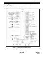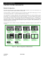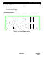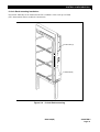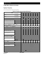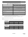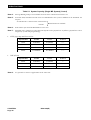
1
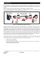
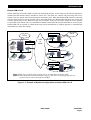
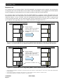
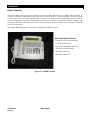
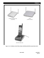
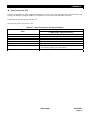
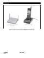
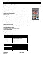
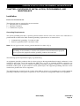
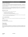
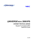
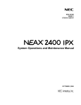
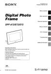
19
ND-91649 (E)
ISSUE 3
General Description
NEC Corporation
LIABILITY DISCLAIMER
NEC Corporation reserves the right to change the specifications, functions, or
features, at any time, without notice.
NEC Corporation has prepared this document for use by its employees and
customers. The information contained herein is the property of NEC Corporation
and shall not be reproduced without prior written approval from NEC Corporation.
NEAX and Dterm are registered trademarks of NEC Corporation.
Copyright 2004
NEC Corporation
Printed in Japan.
All other brand or product names are or may be trademarks or registered trademarks
of, and are used to identify products or services of their respective owners.
ND-91649(E)
ISSUE 3
NEAX 2000 IPS
General Description
TABLE OF CONTENTS
Page
CHAPTER 1 INTRODUCTION ............................................................................................................. 1
System Overview ..................................................................................................................................................1
Hardware Architecture .........................................................................................................................................5
Software Architecture ..........................................................................................................................................7
CHAPTER 2 SYSTEM CONFIGURATION ........................................................................................ 10
Module Configuration.........................................................................................................................................10
Installation Methods ...........................................................................................................................................11
Modules and Installation Hardware ..................................................................................................................14
Circuit Cards .......................................................................................................................................................15
System Conditions .............................................................................................................................................15
CHAPTER 3 TERMINALS ................................................................................................................. 17
Desk Console ......................................................................................................................................................18
Figures of Dterm Series i/Dterm IP.........................................................................................................................22
Wireless System .................................................................................................................................................28
Dterm Softphone (SP30) .......................................................................................................................................37
CHAPTER 4 OVERVIEW OF INSTALLATION, PROGRAMMING, AND MAINTENANCE .............. 39
Installation...........................................................................................................................................................39
Programming ......................................................................................................................................................40
Maintenance ........................................................................................................................................................41
CHAPTER 5 SPECIFICATIONS ........................................................................................................ 42
System Capacity .................................................................................................................................................42
IP Specifications .................................................................................................................................................45
Line Conditions...................................................................................................................................................47
Cell Station/Zone Transceiver Line Conditions...............................................................................................48
Traffic Capacity...................................................................................................................................................49
DRS (Device Registration Server).....................................................................................................................49
ND-91649(E)
TABLE OF CONTENTS
Page i
ND-91649(E)
ISSUE 3
LIST OF ILLUSTRATIONS
Figure
Title
Page
Figure 1-1 NEAX 2000 IPS...................................................................................................................................1
Figure 1-2 NEAX 2000 IPS System Overview....................................................................................................2
Figure 1-3 Example of Network Configuration of Remote PIM over IP ..........................................................3
Figure 1-4 Retrofit MP/FP for Upgrading NEAX 7400 ICS M100 to IPS (Single MP System)........................4
Figure 1-5 Retrofit MP/FP for Upgrading NEAX 7400 ICS M100 to IPS (Dual MP System)...........................4
Figure 1-6 Trunking Diagram of NEAX 2000 IPS ..............................................................................................9
Figure 2-1 Module Configuration of NEAX 2000 IPS......................................................................................10
Figure 2-2 Face Layout of NEAX 2000 IPS ......................................................................................................11
Figure 2-3 Wall-mounting of PIM......................................................................................................................12
Figure 2-4 19-inch Rack-mounting...................................................................................................................13
Figure 3-1 DESK Console .................................................................................................................................18
Figure 3-2 Dterm 2 (White)...................................................................................................................................22
Figure 3-3 Dterm 8 (White)...................................................................................................................................22
Figure 3-4 Dterm 8D (White) ................................................................................................................................22
Figure 3-5 Dterm 16D (White) ..............................................................................................................................23
Figure 3-6 Dterm 32D (White) ..............................................................................................................................23
Figure 3-7 DSS Console (Black).......................................................................................................................23
Figure 3-8 Dterm 16LD (Black) ............................................................................................................................24
Figure 3-9 Analog Port Adapter (APR) ............................................................................................................24
Figure 3-10 Ancillary Device Adapter (ADA)...................................................................................................24
Figure 3-11 Computer Telephony Adapter (CTA)...........................................................................................25
Figure 3-12 IP Adapter (IPW) ............................................................................................................................25
Figure 3-13 System Configuration of Wireless Communications ................................................................29
Figure 3-14 Cell Station (CS), IP Base Station (IP-BS) and PHS Personal Station (PS) .............................33
Figure 3-15 Zone Transceiver (ZT) and PCS Personal Station (PS) .............................................................36
Figure 3-16 SP30 Screen...................................................................................................................................37
LIST OF ILLUSTRATIONS
Page ii
ND-91649(E)
ND-91649(E)
ISSUE 3
LIST OF TABLES
Table
Title
Page
Table 1-1 Technical Terms of NEAX 2000 IPS System ....................................................................................8
Table 2-1 Modules of NEAX 2000 IPS System ................................................................................................14
Table 3-1 Dterm Series i/Dterm IP Specifications and Accessories ..................................................................26
Table 3-2 Combination Pattern of Optional Accessories to the Dterm Series i/ Dterm IP...............................27
Table 3-3 PHS Personal Station (PS) Specifications .....................................................................................30
Table 3-4 2-Wired (U-Interface) Cell Station (CS) Specifications..................................................................31
Table 3-5 IP Base Station (IP-BS) Specifications ...........................................................................................32
Table 3-6 PCS Personal Station (PS) Specifications .....................................................................................34
Table 3-7 Zone Transceiver (ZT) Specifications.............................................................................................35
Table 5-1 System Capacity (Single MP System).............................................................................................42
Table 5-2 IP Specifications ...............................................................................................................................45
Table 5-3 Line Conditions .................................................................................................................................47
Table 5-4 Cell Station/Zone Transceiver Line Conditions .............................................................................48
Table 5-5 Traffic Capacity .................................................................................................................................49
Table 5-6 DRS (Device Registration Server)-System Based .........................................................................49
ND-91649(E)
LIST OF TABLES
Page iii
INTRODUCTION
CHAPTER 1 INTRODUCTION
This document provides an overview of the NEAX 2000 IPS (Internet Protocol Server) stored program control
digital electronic PBX. An introduction to the technical characteristics is included, along with a description of
available system applications.
System Overview
The NEAX 2000 IPS is a full-featured IP-based communications system providing a rich feature set of NEAX
7400 ICS M100MX*, with pure Voice over IP (VoIP) communications (peer-to-peer connections), across
corporate Local and Wide Area Networks (LAN and WAN).
Figure 1-1 NEAX 2000 IPS
The NEAX 2000 IPS supports both pure IP switching (peer-to-peer connections) and Time Division Switching.
The pure IP switching is provided for communications between DtermIPs and for CCIS connections with another
NEAX 2000 IPS/2400 IPX (CCIS over IP). On the other hand, the TDM switching is provided for
communication between legacy stations/trunks. Connections between DtermIP/CCIS over IP and legacy
stations/trunks are made via IP PADs, which converts packet-based voice data to TDM-based voice data, and
vice versa.
* “NEAX 7400 ICS M100MX” is marketed in North/Latin America and Australia as “NEAX 2000 IVS2” and in UK as “NEAX 2000 INTEGRATED
VOICE SERVER.”
ND-91649(E)
CHAPTER 1
Page 1
INTRODUCTION
DtermIP telephones are designed to provide a converged infrastructure at the desktop, with a 100 Base T
Ethernet connection to the LAN and built-in hub for a PC connection to the telephone itself. The system can
provide peer-to-peer connections between DtermIP telephones with voice compression, on a CCIS basis (CCIS
over IP).
PHS cell station can also be connected to LAN with 100 Base T Ethernet as IP-BS.
IPS also provide Windows PC based softphone (Dterm Softphone SP30) to connect to LAN network
and it provides IP enabled Dterm features without the telephone set.
NEAX 2000 IPS
Work
Station
Peer to Peer
term
D
Softphone
IP Switched
MP
MAT
PS
DHCP
Server
IP-BS
Figure 1-2 NEAX 2000 IPS System Overview
The NEAX 2000 IPS can also provide legacy station/trunk interfaces to support the existing Time Division
Multiplexing (TDM) based infrastructure, such as analog telephones, analog networks, and digital networks
(T1/E1, ISDN etc.). The legacy station/trunk interface cards (LT and AP cards) can be accommodated in the
Port Interface Modules (PIM), in the same manner as the NEAX 7400 ICS M100MX*. At maximum
configuration, total system capacity is 768 ports. The system can provide 512 ports for DtermIP telephones and
legacy LT cards, and 256 ports for legacy AP cards. Communications between legacy station/trunks and
DtermIP telephones/IP networks are made via IP PAD, which converts packet-based voice data to TDM-based
voice data, and vice versa. Both peer-to-peer connections and TDM-based connections are controlled by a new
Main Processor (MP) card. The new MP card incorporates a built-in Device Registration Server (DRS) and a
single interface point of IP connections to IP telephone, MATWorX, and OAI/ACD servers.
All Application Processor cards used in NEAX 7400 ICS M100MX* except AP01 and CC01 cards are
available for the IPS system. All Business/Hotel/Data/CCIS/ISDN/WCS features are available. The following
service features are now included on the MP card and do not require the AP01 card.
Authorization Code with AP01
Forced Account Code with AP01
Direct Inward System Access (DISA) with AP01 (For North America)/Remote Access to System with
AP01 (For other than North America)
Call Forwarding set by DISA with AP01
* “NEAX 7400 ICS M100MX” is marketed in North/Latin America and Australia as “NEAX 2000 IVS2” and in UK as “NEAX 2000 INTEGRATED
VOICE SERVER.”
CHAPTER 1
Page 2
ND-91649(E)
INTRODUCTION
Remote PIM over IP
NEAX 2000 IPS can install a PIM at remote site through IP network. At the main site, the NEAX 2000 IPS is
installed and the Remote PIM is installed at remote site. The main site controls call processing and service
feature access for station users located both main and remote sites. When the Remote PIM cannot be connected
with the main site due to the IP network and/or main PBX failure, the Remote PIM initializes the system and
re-starts operation by its own Main Processor (survival mode). In the survival mode, almost all service features
are provided to the station users accommodated in Remote PIM. When IP network/main PBX is recovered, the
Remote PIM can be restored to normal mode with system initialization by manual operation or automatically
(Selectable by system data setting).
Remote-1
PSTN
Main
PSTN
LAN
or
WAN
Remote-2
Remote-3
Note 1: Both legacy and IP stations/trunks can be accommodated in Remote PIM.
Note 2: When the Remote PIM accommodates legacy trunk, the incoming/outgoing calls are
connected to the station through local TDSW.
Figure 1-3 Example of Network Configuration of Remote PIM over IP
ND-91649(E)
CHAPTER 1
Page 3
INTRODUCTION
Migration Path
For customers who are using the NEAX 7400 ICS M100MX*, the migration path is supplied. By replacing the
existing MP card to the new IPS MP card, the NEAX 7400 ICS M100MX* can be upgraded to IP/TSW Hybrid
System including new and enhanced service features introduced with the NEAX 2000 IPS.
For customers who are using NEAX 7400 ICS M100*/M80VS, by replacing existing PN-CP00/CP03 with
Retrofit MP and PN-CP01 with Retrofit FP, the NEAX 7400 ICS M100/M80VS can be upgraded to the NEAX
2000 IPS features. In case of NEAX 7400 ICS M100/M80VS Dual MP System the CP02 is replaced with
CP28-A Retrofit Dual MP. (See the following figure showing replacement of control cards. As for the LT/AP
card conditions after upgrading, refer to the “NEAX 2000 IPS Card Application List”.)
NEAX 7400 ICS M100 before upgrading
NEAX 7400 ICS M100 after upgrading
BSU
BSU
BSU
CP17
BSU
CP01
BSU
BSU
Replace MP/FP
MP: PN-CP00 to PN-CP26-A
FP: PN-CP01 to PN-CP17
Remove FP0 (CP01) mounted
in PIM0
BSU
CP26
BSU
CP00
CP01
Figure 1-4 Retrofit MP/FP for Upgrading NEAX 7400 ICS M100 to IPS (Single MP System)
NEAX 7400 ICS M100 before upgrading
NEAX 7400 ICS M100 after upgrading
BSU
BSU
BSU
BSU
BSU
BSU
CP28
CP28
BSU
CP02
CP02
CP01
17-TW-0.3 CONN CA-A
CP17
BSU
CP01
Replace MP/FP
MP: PN-CP02 to PN-CP28-A
FP: PN-CP01 to PN-CP17
Remove FP0 (CP01) mounted
in PIM0
Figure 1-5 Retrofit MP/FP for Upgrading NEAX 7400 ICS M100 to IPS (Dual MP System)
* “NEAX 7400 ICS M100MX” is marketed in North/Latin America and Australia as “NEAX 2000 IVS2” and in UK as “NEAX 2000 INTEGRATED
VOICE SERVER.”
* “NEAX 7400 ICS M100” is marketed in North America as “NEAX 2000 IVS” and in Australia as “NEAX ICS 120”.
* “NEAX 7400 ICS M80VS” is marketed in Australia as “NEAX ICS 110”.
CHAPTER 1
Page 4
ND-91649(E)
INTRODUCTION
Hardware Architecture
Reduced Hardware with IP-based Architecture
term
The DtermIPs, D
Softphone and IP-BS connected to the LAN do not require any special interface cards*
because they can be interfaced directly with the LAN and connected with peer-to-peer basis. When the DtermIP,
term
D
Softphone or IP-BS is connected to a station/trunk that is using TSW, the speech path between LAN and
term
TSW is made via IP PAD under the call processing control of the MP. The DtermIP, D
Softphone or IP-BS
can be expanded simply adding the terminal itself. With this system architecture, the hardware such as DLC,
CSI, CSH, PIM, Power Supply etc. is reduced and easy moves, adds, and changes can be realized.
Standard TDM Hardware
Peer-to-Peer IP Hardware
Line & Trunk Cards
Application Processors
Firmware Processors
IP PAD
(8IPLA, 24IPLA, 32IPLA, 16VCT)
Ether Card (M606)
Powerful, One-board Main Processor (MP) with Integrated Functionality
The NEAX 2000 IPS Main Processor (MP) is the heart of pure IP connections and TDM-based connections.
The MP employs a high-speed CPU, which is equivalent with Pentium. With this processing power and
System On Chip (SOC) technology, the MP integrates Device Registration Server (DRS), AP01 (OAI)
functions, which are provided by an additional card in the previous M100MX*. Also, by means of today’s
advanced LSI technology, the MP card size is minimized and On-board Ethernet Interface card is mounted on
the MP without using an additional slot space in the PIM. This interface card is linked with LAN for call
control processing of DtermIP and inter-work with MATWorX and OAI server.
Enhanced Built-in Firmware Processor (FP) on MP
The NEAX 7400 ICS M100MX* requires the FP card in PIM0 when the system is configured with 3 or more
PIMs. In case of the NEAX 2000 IPS, the FP in PIM0 is not required since the Built-in FP function in new MP
has been improved and it provides more call processing capability. (FP is used in PIM2, 4 and 6.)
* DLC, CSI and CS handler.
ND-91649(E)
CHAPTER 1
Page 5
INTRODUCTION
Extended Application Processor (AP) Port Capacity
The NEAX 2000 IPS provides a maximum of 256 AP ports and it is independent of the 512 ports for the
Line/Trunk (LT), therefore, more AP cards such as T1/E1 digital link cards can be used in the system.
Universal Slot
One PIM provides 12 card slots for Line/Trunk (LT). Also, these card slots can be used for Application
Processor (AP) cards without complicated limitation. This makes easy quotation and installation, and more AP
cards can be mounted in one PIM.
Unified Circuit Card Size
All the circuit cards for the NEAX 2000 IPS are designed in one size (PN-type), and installed in the PIM. This
maximizes the efficiency of slot utilization of the PIM.
High Density Line/Trunk Cards
The major line/trunk cards used in the NEAX 2000 IPS are provided with 8 circuits per card. This allows the
physical system size to be compact.
Various Power supply system
AC Input system
The PIM houses the AC/DC power supply with various AC (100V/200V) input that outputs various DC
voltage required for several internal cards.
The AC/DC power supply has function of Battery charger. Thus, system can be backed up with battery
according to necessity.
The PIM also houses optional DC/DC power supply for the cards that require -48V power such as CSI
card used for interface of cell station/zone transceiver.
DC Input system
NEAX 2000 IPS also provides the DC/DC power supply with -48V DC input house in the PIM that
outputs various DC voltage required for several internal cards.
Thus, NEAX 2000 IPS can be installed at various powering environment.
Various Installation Methods
To meet the specific needs of the customer’s environment, the NEAX 2000 IPS provides the following
installation methods:
Floor Standing Installation
Wall-mounting Installation
IEC standard 19-inch Rack-mounting Installation
CHAPTER 1
Page 6
ND-91649(E)
INTRODUCTION
Software Architecture
Built-in DRS (Device Registration Server) on MP
The NEAX 2000 IPS incorporates DRS (Device Registration Server) on the MP. DRS provides Log-in/Logout management of DtermIP including Registration and Authentication. Also, the built-in DRS can be interworked with DHCP server to provide easy administration on IP address.
Office Data Backup Enhancement
The office data of the NEAX 2000 IPS is stored in Flash ROM, therefore the backup period is extended
compared with previous M100MX series which were using RAM with battery.
* M100MX is marketed in North/Latin America and Australia as “NEAX 2000 IVS2” and in UK as “NEAX 2000 INTEGRATED VOICE SERVER.”
ND-91649(E)
CHAPTER 1
Page 7
INTRODUCTION
Technical Terms
Table 1-1 Technical Terms of NEAX 2000 IPS System
SYMBOL
DESCRIPTION
SYMBOL
DESCRIPTION
AMP
Amplifier Trunk Card
LC
Line Circuit Card
(for Single Line Telephone)
AP00
SMDR/Hotel Application Card
LDT
LD Trunk Card
BGM
External Music Source for Dterm
Back Ground Music Service
LLC
Long Line Circuit Card
BRT
Basic Rate Interface Trunk Card
M10
Optical Interface Card
CCH
Common Channel Handler Card
MAT
Maintenance Administration Terminal
CFT
6/10 Party Conference Trunk Card
MDF
Main Distribution Frame
CIS
Call Information System
MEM
Main Memory
CIR
CALLER ID Receiver Trunk Card
MFR
MF Receiver/ MFC Receiver/Sender
Card
COT
C.O. Trunk Card
MLDT
Melody Trunk
CSI
CS/ZT Interface Card
MODEM
Modem
CS/ZT
Cell Station (For Australia/Others)
Zone Transceiver (For North America/
Latin America)
MP
Main Processor Card
DAT
Digital Announcement Trunk Card
PFT
Power Failure Transfer
DCH
D-channel Handler Card
PMS
Property Management System
DIT
DID Trunk Card
OAI
Open Application Interface
DK
External Relay/Key Interface Card
ODT
OD Trunk Card (2/4 wire E&M)
DLC
Digital Line Circuit Card
(for Dterm, ATTCON, DESKCON)
PBR
PB Receiver Card
DSS
DSS Console
PBSND
PB Sender
DTI
Digital Trunk Interface Card
PLO
Phase Locked Oscillator
DTG
Digital Tone Generator
PS
Personal Station
ETHER
Ethernet Control Card
PRT
ISDN Primary Rate Interface Trunk
Card
ICH
ISDN-channel Handler Card
SMDR
Station Message Detail Recording
ILC
ISDN Line Circuit Card
TDSW
Time Division Switch
IP-BS
IP Base Station
TNT
Tone/Music Source Interface Card
IP PAD
IP Packet Assembler/Disassembler Card
VCT
CODEC Card
IPT
IP Trunk Card
VM
Voice Mail Card
KEY
External Key
16CFT
16-Circuit Four-Party Conference Trunk
CHAPTER 1
Page 8
ND-91649(E)
INTRODUCTION
Trunking Diagram
This figure shows a typical trunking diagram of the NEAX 2000 IPS system.
Figure 1-6 Trunking Diagram of NEAX 2000 IPS
ND-91649(E)
CHAPTER 1
Page 9
SYSTEM CONFIGURATION
CHAPTER 2 SYSTEM CONFIGURATION
Module Configuration
The NEAX 2000 IPS consists of Port Interface Modules (PIM) depending on the system configuration, and
there are two types of PIMs; “Physical” PIM and “Virtual” PIM.
The Physical PIM is a “hardware” PIM and is used to accommodate an MP, FPs, IP PADs, legacy LT an AP
cards, and power supply units. One Physical PIM provides up to 64 ports.
The Virtual PIM is a “software” PIM and is used to assign DtermIP telephones, Dterm SP30 or IP-BS by system
programming. One Virtual PIM provides up to 64 DtermIP telephones. The system consists of up to 8 PIMs,
by the combination of Physical PIMs and Virtual PIMs, thus providing 448 ports for Dterm IP telephones and
512 ports for legacy LT cards. The total number of ports for DtermIP telephones and legacy LT cards must be
512 or fewer, so that the number of Physical PIMs decreases when that of Virtual PIMs (= number of DtermIP
telephones) increases. For example, when 256 legacy LT ports are required (= four Physical PIMs), the
maximum number of Dterm IPs is 256.
The figure below shows examples of 512-port configuration by combination of legacy LT ports and Dterm IP
telephones.
PIM #3
PIM #2
PIM #1
PIM #0
PIM #7
PIM #6
PIM #5
PIM #4
PIM #3
PIM #2
PIM #1
PIM #0
PIM #7
PIM #6
PIM #5
PIM #4
PIM #3
PIM #2
PIM #1
PIM #0
PIM #7
PIM #6
PIM #5
PIM #4
PIM #3
PIM #2
PIM #1
PIM #0
PIM #7
PIM #6
PIM #5
PIM #4
64 LT ports
+ 448 Dterm IPs
128 LT ports
+ 384 Dterm IPs
192 LT ports
+ 256 Dterm IPs
256 LT ports
+256 Dterm IPs
PIM #3
PIM #2
PIM #1
PIM #0
PIM #3
PIM #2
PIM #1
PIM #0
PIM #3
PIM #2
PIM #1
PIM #0
PIM #3
PIM #2
PIM #1
PIM #0
PIM #7
PIM #6
PIM #5
PIM #4
PIM #7
PIM #6
PIM #5
PIM #4
320 LT ports
+ 128 Dterm IPs
384 LT ports
+ 128 Dterm IPs
PIM
PIM
Physical PIM
Virtual PIM
Figure 2-1
CHAPTER 2
Page 10
PIM #7
PIM #6
PIM #5
PIM #4
448 LT ports
+ 0 Dterm IPs
512 LT ports
+ 0 Dterm IPs
Module Configuration of NEAX 2000 IPS
ND-91649(E)
PIM #7
PIM #6
PIM #5
PIM #4
SYSTEM CONFIGURATION
Installation Methods
The NEAX 2000 IPS provides three installation methods as follows:
Floor Standing Installation
Wall Mounting Installation
19-inch Rack Mounting Installation
Floor Standing Installation
In Floor Standing Installation, the NEAX 2000 IPS is comprised of up to 8 Port Interface Modules (PIMs).
PIM #3
PIM #2
PIM #2
PIM #1
PIM #1
PIM #1
PIM #0
PIM #0
PIM #0
PIM #0
BASE
BASE
BASE
BASE
(64 ports)
(128 ports)
(192 ports)
(256 ports)
PIM #3
PIM #3
PIM #3
PIM #3
PIM #7
PIM #2
PIM #2
PIM #2
PIM #6
PIM #2
PIM #6
PIM #1
PIM #1
PIM #5
PIM #1
PIM #5
PIM #1
PIM #5
PIM #0
PIM #4
PIM #0
PIM #4
PIM #0
PIM #4
PIM #0
PIM #4
BASE
BASE
BASE
BASE
BASE
BASE
BASE
BASE
(320 ports)
(384 ports)
Figure 2-2
(448 ports)
(512 ports)
Face Layout of NEAX 2000 IPS
ND-91649(E)
CHAPTER 2
Page 11
SYSTEM CONFIGURATION
Wall-mounting Installation
The NEAX 2000 IPS can be wall-mounted with single or multiple PIM (MAX. 8) configuration.
Figure 2-3
CHAPTER 2
Page 12
Wall-mounting of PIM
ND-91649(E)
SYSTEM CONFIGURATION
19-inch Rack-mounting Installation
The NEAX 2000 IPS can be mounted in the IEC-standard 19-inch rack up to 4 PIMs.
(IEC: International Electro-technical Commission)
19” BRACKET(A)
19” BRACKET(B)
Figure 2-4
19-inch Rack-mounting
ND-91649(E)
CHAPTER 2
Page 13
SYSTEM CONFIGURATION
Modules and Installation Hardware
The NEAX 2000 IPS is comprised of up to 8 Port Interface Modules (PIMs).
Modules
(1) Port Interface Module (PIM)
A PIM provides 13 card slots for common control, Line/Trunk (LT), and Application Processor (AP) cards. It
also houses an AC/DC Power Supply (or DC/DC Power Supply), optional DC/DC Power Supply (for -48V),
and batteries for protection from short-term (about 30 min.) power interruption.
Four champ connectors for Line/Trunk (LTC 0 to 3) are located at the lower front side of the PIM.
A PIM provides a maximum of 12 card slots for Line/Trunk (LT) and Application Processor (AP) cards. At
maximum configuration, the system is comprised of 8 PIMs.
PIM MD
PIM MD
(PIM3)
(PIM7)
PIM MD
PIM MD
(PIM2)
(PIM6)
PIM MD
PIM MD
(PIM1)
(PIM5)
PIM MD
PIM MD
(PIM0)
(PIM4)
Single MP System
PIM MD
PIM MD
(PIM3)
(PIM7)
PIM MD
PIM MD
(PIM2)
(PIM6)
PIM MD
PIM MD
(PIM1)
(PIM5)
PIM MF
PIM MD
(PIM4)
(PIM0)
Dual MP System
(2) Battery Module (BATTM)*
The BATTM is an optional module for installing optional long-term (about 3 hours) backup batteries. The
BATTM is designed to accommodate batteries covering up to a 4-PIM system (2 BATTMs support maximum
system configuration).
The BATTM is available for Floor Standing Installation. (When the system is Wall-mounting/19-inch
Rack-mounting configuration, the BATTM cannot be installed with the PIM.)
Table 2-1
Abbrev
PIMMD
PIM MF
BATTM
Modules of NEAX 2000 IPS System
Name Code
SN1617 PIMMD
SN1658 PIMMF
SN1619 BATTMB
Remarks
PIM 0 ~ PIM 7
PIM0 for dual MP system
1/STACK, Max.2/system
* Battery Module is available for Latin America.
CHAPTER 2
Page 14
ND-91649(E)
SYSTEM CONFIGURATION
Circuit Cards
The circuit cards used for NEAX 2000 IPS are divided into the following three types. According to these card
types, the mounting location of card and port allocation of the Time Division Switch are varied.
Common Control Cards
- Main Processor (MP)
- Firmware Processor (FP)
Line/Trunk (LT) Cards
- IP PAD, Line Circuit (LC), Central Office Trunk (COT), Tie Line Trunk (LDT/ODT), etc.
Application Processor (AP) Cards
- SMDR/PMS/CIS/Hotel Printer Interface (AP00)
- T1/E1 Digital Trunk Interface (DTI)
System Conditions
Conditions for Peer-to-Peer Connection
For the communication between Dterm IPs, the voice data is transmitted and received directly, without
converting voice packets into PCM and voice compression in the system.
Conditions for CCIS Connection
Dterm IP to Dterm IP connection (Peer-to-Peer connection) via CCIS is available only when the destination
office uses NEAX 2000 IPS or NEAX 2400 IPX.
The built-in CCH-IPT of MP card can be connected to max. 127 trunks.
The system provides only Point-to-Multipoint connection.
Conditions for H.323 Connection
When connecting to the IP network with H.323 protocol, the IPT card is required.
When connecting to the IP network with H.323 protocol, the voice data is transmitted and received via the
IP-PAD card.
Conditions for Legacy Interface (LT/AP)
All Application Processor cards used in NEAX 7400 ICS M100MX* except AP01 and CC01 cards are
available for the system.
All Line/Trunk cards used in NEAX 7400 ICS M100MX* are available for the system.
* “NEAX 7400 ICS M100MX” is marketed in North/Latin America and Australia as “NEAX 2000 IVS2” and in UK as “NEAX 2000 INTEGRATED
VOICE SERVER.”
ND-91649(E)
CHAPTER 2
Page 15
SYSTEM CONFIGURATION
Conditions for Maintenance
MATWorX can be used as the maintenance program for NEAX 2000 IPS. Direct connection (RS-232C),
Modem connection and LAN (TCP/IP) connection are available to connect to the MAT (Maintenance
Administration Terminal).
Conditions for DRS
DRS = Device Registration Server
The Dterm IP registration is executed by the DRS-System Based.
for the Dterm IP registration.
The DRS can be used as the Proxy server.
CHAPTER 2
Page 16
ND-91649(E)
The DRS-Network Based is not available
TERMINALS
CHAPTER 3 TERMINALS
A variety of terminal equipment may be connected to the NEAX 2000 IPS. The following equipment may be
installed with the system.
Attendant Console
Desk Console
Dterm Series i
Dterm 2 (White/Black Color)
Dterm 8 (White/Black Color)
Dterm 8D (White/Black Color)
Dterm 16D (White/Black Color)
Dterm 32D (White/Black Color)
Dterm 16 LD (White/Black Color)
:
:
:
:
:
:
2-button terminal
8-button terminal
8-button terminal with LCD display
16-button terminal with LCD display
32-button terminal with LCD display
16-button LD terminal with LCD display
Dterm IP
Dterm 8D (White/Black Color)
Dterm 16D (White/Black Color)
:
:
8-button terminal with LCD display
16-button terminal with LCD display
PS (Wireless Handset)
PHS model
PCS model
Dterm SP30 (or Dterm SP20) (IP Softphone)
ND-91649(E)
CHAPTER 3
Page 17
TERMINALS
Desk Console
The SN716 Desk Console has an ergonomic design and provides full access to all PBX Console features. It
connects to the NEAX 2000 IPS using the same circuit cards as the Dterm 75 Series terminals. The SN716 Desk
Console operates on a switched-loop basis with a maximum of 6 Attendant loops terminating at each console on
the associated Interface card. The Attendant uses these loops for answering, originating, holding, extending, and
reentering calls. When Attendant loop release is used, the number of loops is effectively increased to a maximum
of 12 for each console.
The NEAX 2000 IPS supports a maximum of eight SN716 DESK Consoles.
SN716 DESKCON Features
• Character LCD (4x40 characters)
• LCD designation strips
• Software-controlled LCD loop key
• Full access to PBX features
• Headset connectivity
• Recorder connectivity
Figure 3-1 DESK Console
CHAPTER 3
Page 18
ND-91649(E)
TERMINALS
Dterm Series i/Dterm IP Digital Multifunction Terminals
The Dterm Series digital multifunction/multiline terminal is available in two colors to meet the needs of various
users based on the features and types of communications each end user requires.
Dterm Series i
Dterm 2 (White/Black Color)
Dterm 8 (White/Black Color)
Dterm 8D (White/Black Color)
Dterm 16D (White/Black Color)
Dterm 32D (White/Black Color)
Dterm 16LD (White/Black Color)
term
D IP
Dterm 8D (White/Black Color)
Dterm 16D (White/Black Color)
:
:
:
:
:
:
2-button terminal
8-button terminal
8-button terminal with LCD display
16-button terminal with LCD display
32-button terminal with LCD display
16-button LD terminal with LCD display
:
:
8-button terminal with LCD display
16-button terminal with LCD display
Features most commonly used in daily operation and functions required by the user are provided by the following
dedicated buttons/lamp.
Hold - Press key to place an internal or external call on hold.
TRANSFER - Allows the station user to transfer established calls to another station without attendant
assistance.
ANSWER - When LED on this key is lighted, press key to answer a waiting call.
SPEAKER - Controls the built-in speaker that can be used for Hands Free Dialing/Monitoring and Voice
Call.
REDIAL - Press key to activate the redial feature, then press redial and scroll back through numbers that
have been dialed. When desired number is displayed, press the key to activate dialing.
CONF - Press key to establish a three-way conversation.
RECALL - Press key to terminate established call and returns to the internal dial tone.
FEATURE - Used to activate terminal setup functions and to program One-Touch Speed Dial/Feature Keys.
DIRECTORY - Press key to activate speed calling.
MESSAGE - Press key to access the voice mail system.
MIC - Press key to respond hands free. LED on this key lights during speakerphone operation.
This ergonomically designed terminal provides; larger keypad buttons for dialing convenience, an expanded
three-line by 24-character LCD display, tiltable legs with nonskid feet, and a highly visible call/message indicator
lamp.
All models have built-in hands-free unit as standard. The terminal is connected to the NEAX 2000 IPS via a
single pair of cabling, thus optimizing existing cabling environment. These advantages make the Dterm Series i
terminals the standard for telephones that effectively meet today's business requirements.
ND-91649(E)
CHAPTER 3
Page 19
TERMINALS
Dterm Series i/Dterm IP Lineup
Dterm 2 (2-button Dterm)
This Dterm Series Digital Multi-line Terminal is equipped with 8 dedicated Function keys (such as Hold,
TRANSFER, ANSWER, SPEAKER, REDIAL, CONF, RECALL and FEATURE), 2 programmable
Line/Feature keys (each with a two-color LED). 2 programmable keys are flexible and can be assigned to any
outside line connected to the system, to another station line, or as a feature button. The terminal is available in two
colors - Black (BK) and Ivory White (WH).
Dterm 8 (8-button Dterm)
This Dterm Series Digital Multi-line Terminal is fully modular with 11 dedicated Function keys, 8 programmable
Line/Feature keys (each with a two-color LED), built-in Speakerphone, built-in Headset Jack,
Tone/Volume/Contrast control, Tilt Stand, and a large LED to indicate incoming calls and messages. The
terminal is available in tow colors - Black (BK) and Ivory White (WH).
Dterm 8D (8-button Dterm with Display)
This Dterm Series Digital Multi-Line Terminal is equipped with 11 dedicated Function keys, 8 programmable
Line/Feature keys (each with a two-color LED), built-in Speakerphone, built-in Headset Jack,
Tone/Volume/Contrast control, Tilt Stand, 3 line by 24-character LCD Display Panel (adjustable & detachable),
four Soft Keys, and a Large LED to indicate incoming calls and messages. This terminal is available in two colors
- Black (BK) and Ivory White (WH).
Dterm 16D (16-button Dterm with Display)
This Dterm Series Digital Multi-Line Terminal is equipped with 11 dedicated Function keys, 16 programmable
Line/Feature keys (each with a two-color LED), built-in Speakerphone, built-in Headset Jack,
Tone/Volume/Contrast control, Tilt Stand, 3 line by 24-character LCD Display Panel (adjustable & detachable),
four Soft Keys, and a Large LED to indicate incoming calls and messages. This terminal is available in two colors
- Black (BK) and Ivory White (WH).
Dterm 32D (32-button Dterm with Display)
This Dterm Series Digital Multi-Line Terminal is equipped with 11 dedicated Function keys, 32 programmable
Line/Feature keys (each with a two-color LED), built-in Speakerphone, built-in Headset Jack,
Tone/Volume/Contrast control, Tilt Stand, 3 line by 24-character LCD Display Panel (adjustable & detachable),
four Soft Keys, and a Large LED to indicate incoming calls and messages.
Dterm 16LD (DESI Less 16 LD button Dterm with Display)
This Dterm Series Digital Multi-Line Terminal is equipped with 11 dedicated Function keys, 16 programmable
Line/Feature keys (each with a two-color LED), built-in Speakerphone, built-in Headset Jack,
Tone/Volume/Contrast control, Tilt Stand, 3 line by 24-character LCD Display Panel (adjustable & detachable),
four Soft Keys, and a Large LED to indicate incoming calls and messages. This terminal is available in two
colors - Black (BK) and Ivory White (WH).
CHAPTER 3
Page 20
ND-91649(E)
TERMINALS
Dterm Series i/Dterm IP Accessories
Direct Station Selection (DSS) Console
This Console is equipped with 60 programmable line keys (each with a two-color LED). These keys can be
programmed as Direct Station keys, Function keys, or Line keys. The DCU-60 Console is available in two colors
- Black (BK) and Ivory White (WH).
Analog Port Adapter (APR)
The Analog Port Adapter with Ringing (APR-U) provides an interface for installing single line telephones (SLTs),
modems*. By installing the APR-U, calls may be initiated via a PC modem and switched to voice operation if
desired. Data calls at a maximum speed of 28.8 kbps are also supported through the APR-U. The APR-U also has
the added benefit of detecting incoming ringing signals. By providing ring detection, the user may wish to install
a personal fax machine or an answering machine at the workstation and connect them through the Dterm Series
instrument for convenience.
* When a modem is installed to the Dterm Series Multi-line terminal with the APR-U, the modem and the Dterm
Series Multi-line Terminal (handset, speakerphone, headset) cannot be used simultaneously.
Ancillary Device Adapter (ADA)
The Ancillary Device Adapter (ADA-U) allows for a direct connection from the Dterm Series i/ Dterm IP terminal to
a tape recorder for logging/recording telephone calls. A dedicated set of input connectors is also provided for a
recording tone unit to inform the parties that the call is being recorded. The ADA-U does not require an AC
adapter.
Computer Telephony Adapter (CTA)
The Computer Telephony Adapter (CTA) provides Dterm with a connection to desktop PC, allowing users to
operate Windows®-based Computer Telephony application such as ClientPhone 32.
IP Adapter (IPW)
The IP Adapter Unit (IPW) provides two 10/100 Base-T Ethernet ports to the Local Area Network (LAN) and a
built-in switching hub for a PC connection to the adapter itself.
Operating power can be fed by either an AC/DC adapter unit or a power patch panel connected to the LAN
switch/hub.
When the IPW is attached to the Dterm, other optional accessories cannot be attached except for Ancillary Device
Adapter (ADA).
Wall Mount Unit (WMU)
The Wall Mount Unit (WMU) allows the Dterm Series terminal to be conveniently mounted vertically when desk
space is not available.
ND-91649(E)
CHAPTER 3
Page 21
TERMINALS
Figures of Dterm Series i/Dterm IP
* Dterm 2 (Black) is also supported.
* Dterm 8 (Black) is also supported.
* Dterm 8 D(Black) is also supported.
CHAPTER 3
Page 22
Figure 3-2 Dterm 2 (White)
Figure 3-3 Dterm 8 (White)
Figure 3-4 Dterm 8D (White)
ND-91649(E)
TERMINALS
* Dterm 16 D (Black) is also supported.
* Dterm 32 D (Black) is also supported.
Figure 3-5 Dterm 16D (White)
Figure 3-6 Dterm 32D (White)
* DSS Console (White) is also supported.
Figure 3-7 DSS Console (Black)
ND-91649(E)
CHAPTER 3
Page 23
TERMINALS
* Dterm 16LD (White) is also supported.
Figure 3-8 Dterm 16LD (Black)
Figure 3-9 Analog Port Adapter (APR)
Figure 3-10 Ancillary Device Adapter (ADA)
CHAPTER 3
Page 24
ND-91649(E)
TERMINALS
Figure 3-11 Computer Telephony Adapter (CTA)
Figure 3-12 IP Adapter (IPW)
ND-91649(E)
CHAPTER 3
Page 25
TERMINALS
Dterm Series i/Dterm IP Specifications
The specifications of the Dterm Series i/Dterm IP are shown in below.
Table 3-1 Dterm Series i/Dterm IP Specifications and Accessories
Specifications/Description
Dedicated Function Keys
Line/Feature
Access/Programmable Feature
Access Key
LCD
Dterm 8D
D
2 D
8 D
Dterm
Series i
IP
8
11
11
term
2
term
Dterm
32D
Dterm
16LD
11
11
32
16
3 Lines
24
Characters
8
16
None
None
3 Lines
24 Characters
3 Lines
24 Characters
-
-
LED
(Green
/Red)
LED
(Green
/Red)
LED
(Green
/Red)
LED
(Green
/Red)
3 Lines
24
Charac
- ters
LED
(Green
/Red)
Yes
Yes
Yes
-
Yes
-
Yes
Yes
Yes
Yes
Yes
Yes
Yes
Optional
Yes
No
Yes
Yes
Yes
Yes
Yes
Yes
Yes
Yes
Yes
Yes
Yes
Yes
Yes
Yes
Yes
Yes
Yes
Yes
Yes
Yes
Yes
Yes
Yes
Yes
Yes
Yes
Yes
Yes
Yes
-
-
Yes
Yes
Yes
Yes
White
or
Black
No
White
or
Black
No
White or
Black
White or
Black
Yes
Yes
Soft Keys
Optional Accessories
DSS/BLF console*
No
Ancillary Device Adapter
No
(ADA-U)
Analog Port Adapter w/ Ringing
No
(APR-U)
PC Telephony Adapter (CTA)*
No
IP Adapter (IPW)*
No
* It requires an AC/DC adapter.
** Displayed characters are Only English.
CHAPTER 3
Page 26
Dterm 16D
D
Dterm
Series i
IP
11
term
8
Indication on Line/Feature Keys
Hands Free Operation:
Half Duplex
Call/Message Indicator
Adjustable Legs (Built-in
WMU)
Volume Control Handset
(Receiver)
Volume Control Speakerphone
(Receiver)
Volume Control Handset
(Receiver)
Ring Volume Control
Brightness Control-LCD
Contrast
Housing Color
term
White
or
Black
Yes
LCD**
Icon
White or
Black
Yes
Yes
Yes
No
Yes
No
Yes
Yes
Yes
Yes
No
Yes
No
Yes
Yes
Yes
Yes
No
Yes
No
Yes
Yes
Yes
No
Yes
Yes
No
No
Yes
Yes
No
No
Yes
Yes
Yes
Yes
ND-91649(E)
TERMINALS
Table 3-2 Combination Pattern of Optional Accessories to the Dterm Series i/ Dterm IP
Combination Pattern
1
2
3
4
5
6
7
8
9
10
X : Available
APR
ADA
X
CTA
IPW
X
X
X
X
X
X
X
X
ND-91649(E)
X
X
X
WMU
X
X
X
X
X
X
X
X
X
X
CHAPTER 3
Page 27
TERMINALS
Wireless System
A mobile work force no longer has to be dependent on special technology.
With personal telephone and Wireless Communication System, employees can travel throughout a multistored
building or across a large industrial complex and continue to stay in constant touch with customers and
colleagues.
NEAX 2400 IPX has built-in wireless system for providing wireless communication, it can support up to 256
users.
Versatile Communication Tool for a variety of industries
(1) Business Offices
Even when an employee in the company cannot be reached at their desk, the wireless communication service
can put them in touch immediately.
A call from a customer can be connected directly to the called employee without holding the call or asking
the customer to call back. This means improved customer satisfaction.
Even when a company has offices in several different buildings, just install the connection unit, then all you
have to do is carry the handy phone set to place or receive calls anywhere. Since the wireless communication
service does not require reinstallation of equipment or re-registration of extension numbers whenever you
change the office layout, it can effectively reduce costs.
(2) Medical Centers (or Hospitals)
By assigning a personal handy phone to each doctor and nurse, they can be reached anywhere in the hospital
for faster response to emergencies.
Better service can be offered to in-patients as well as patients with walking disabilities by lending them
handy phone sets.
Speedier communications is an extra touch that will make the patients reassured that they are in good hands.
(3) Plants
The wireless communication service allows bi-directional communications in large working areas such as
plants, warehouses, and factories.
Instructions and messages from the office or reports from the plant can be conveyed in real-time to help
improve productivity.
The wireless service also makes it possible to verify the process while moving over a line or to check the
inventory in the warehouse with someone in the office over the telephone.
Use the optional headset for hands-free communications without work interruptions for better safety and
work efficiency.
CHAPTER 3
Page 28
ND-91649(E)
TERMINALS
(4) Department Stores and Hotels
On the sales floor, the wireless communication service allows a clerk to check inventory for a customer or
promptly call the manager. When holding an even or exhibition, or when changing the sales floor layout, the
wireless service requires no cable laying or transfer, so telephone installation and removal are simple.
At hotels and resorts, the wireless communication service can be used between the front desk and the rest of
the complex and for communications and instructions between staff members of an event in the complex.
Assign each security guard a handy phone set, and you can realize more systematic reporting and higher
mobility, as well as higher security in the event of an emergency.
System Configuration
Figure 3-13 shows the system configuration of NEAX 2000 IPX wireless communications system.
Figure 3-13 System Configuration of Wireless Communications
The wireless communications function conforms to the ARIB standard version 2 RCR STD-28 standarized in
Japan as the PHS (Personal Handyphone System) or TIA/EIA-667 PACS WUPE standarized in USA as the
unlicensed PCS (Personal Communications System) in accordance with market’s regulations.
The PS (Personal Station), BS/ZT (Base Station/Zone Transceiver), IP-BS (IP Base Station) and the NEAX 2000
IPS provide wireless communications service on the private use.
ND-91649(E)
CHAPTER 3
Page 29
TERMINALS
Personal Handyphone System (PHS)
Personal Station (PS)
The PS (Personal Station) incorporates the 32 Kbps ADPCM encoding technique and privacy function so that
you can talk about even important matters in a noise-free, very clear voice.
Since the PS is light-weight and compact in size, it can conveniently carried around.
Here are specifications for the PS and its major functions.
Specification of Personal Station
Table 3-3 PHS Personal Station (PS) Specifications
Item
Frequency
RF Power
Voice Coding/Decoding System
Basic Specifications
Continuous Talk Time
Continuous Standby Time
Waterproof
Dimensions
Volume
Weight
Specifications
1.895 ~ 1.918 GHz
10mW (Average)
32 Kbps ADPCM
Compliance with ARIB Standard RCR STD-28 version 2
Approx. 6 Hours
Approx. 500 Hours
Supported
Approx. 40 (W) × 24 (D) × 130 (H) mm (Excluding Antenna)
Approx. 105 cc
Approx. 115 g
Feature
<< Display/Indication >>
24-Digits Capacity (for Dialing and Storage)
11-Characters × 2-Lines Large Display + Indicator
Battery Indicator
Receiving Signal Strength Indicator
Own Telephone Number Display
Out of Area Indicator
Softkey Display
2-Line Operation (L1 & L2)
<< Calling >>
Incoming Call Indicator
DTMF Dialing
Vibrator Alert
Automatic Answer
<< Memory >>
Directory Dial (100 numbers with name)
Speed Dial (20 numbers with name)
Last Number Redial (10 numbers)
Calling Party Number (10 numbers)
Scrolling by Name on Memory Location
<< General >>
Back Lighting
Low Battery Alarm
Volume Control (ringing tone, earpierce)
Voice Mail Indication (VMI)
Lock Function
Name Display
CHAPTER 3
Page 30
ND-91649(E)
TERMINALS
Cell Station (CS)
Because of its small size, light weight and slenderness, the CS can be installed anywhere...the wall surface, the
ceiling or behind the ceiling. In addition, its expansion or relocation can be smoothly performed.
Followings are the specifications for the CS.
Specification of Cell Station
Table 3-4 2-Wired (U-Interface) Cell Station (CS) Specifications
Item
Specifications
Radio Interface
RCR STD-28 Ver. 2 (RF Power : 10mW Average)
PBX Interface
2-Wire (metallic)
Maximum Simultaneous Access per CS
3 Personal Stations
Volume
Approx. 700 cc
Size
Approx. 141 (W) × 183 (D) × 36 (H) mm (Excluding Antenna)
Weight
Approx. 380 g
Power Supply
PBX Power Supply (DC-48V)
Local Power Supply (AC 100V/200V)
Application
In Door Type
* This CS can download new soft program from MAT, so it can easily maintenance and operation.
ND-91649(E)
CHAPTER 3
Page 31
TERMINALS
IP Base Station (IP-BS)
PHS Base Station is installed on the IP network and LAN, and Wireless Communication System can be built.
Management such as wiring can be reduced by IP-ization.
Specification of IP Base Station
Table 3-5 IP Base Station (IP-BS) Specifications
Item
Wire Interface
Wireless Interface
Number of Simultaneous calls
Operating environment
Power consumption
Voice codec
Dimensions
Power Supply
Specifications
10M/100M RJ45 Connecter 1port
RCR STD-28 3rd edition
3CH
0-40 degree, 7W
G.711, G.729a, G.723.1
160 × 159 × 40mm (w/o an antenna)
Local power supply:AC-R UNIT
Central power supply:
Correspond to electric supply HUB
SN8051 POESWEA-A(NEC)
Catalyst 3550-24 PWR (Cisco)
Catalyst Inline Power Patch Panel (Cisco)
* This IP-BS can download new soft program from MAT, so it can easily maintenance and operation.
CHAPTER 3
Page 32
ND-91649(E)
TERMINALS
2-Wired Cell Station (CS)
(U-Interface)
IP-BS
(TCP/IP or Ether)
Personal Station (PS)
Figure 3-14 Cell Station (CS), IP Base Station (IP-BS) and PHS Personal Station (PS)
ND-91649(E)
CHAPTER 3
Page 33
TERMINALS
Personal Communication System (PCS)
Personal Station (PS)
The PS (Personal Station) incorporates the 32 Kbps ADPCM encoding technique and privacy function so that
you can talk about even important matters in a noise-free, very clear voice.
Since the PS is light-weight and compact in size, it can conveniently carried around.
Here are specifications for the PS and its major functions.
Specification of Personal Station
Table 3-6 PCS Personal Station (PS) Specifications
Item
Frequency
RF Power
Voice Coding/Decoding System
Basic Specifications
Continuous Talk Time
Continuous Standby Time
Waterproof
Dimensions
Volume
Weight
Specifications
1.920 ~ 1.930 GHz
6.8 mW (Average)
32 Kbps ADPCM
Compliance with TIA/EIA-667 PACS WUPE
Approx. 6 Hours
Approx. 500 Hours
Supported
Approx. 40 (W) × 24 (D) × 130 (H) mm (Excluding Antenna)
Approx. 105 cc
Approx. 115 g
Feature
<< Display/Indication >>
24-Digits Capacity (for Dialing and Storage)
11-Characters × 2-Lines Large Display + Indicator
Battery Indicator
Receiving Signal Strength Indicator
Own Telephone Number Display
Out of Area Indicator
Voice mail indication
Softkey Display
2-Line Operation (L1 & L2)
<< Calling >>
Incoming Call Indicator
DTMF Dialing
Vibrator
Alert
Automatic Answer
<< Memory >>
Directory Dial (100 numbers with name)
Speed Dial (20 numbers with name)
Last Number Redial (5 numbers)
Calling Party Number (5 numbers)
Scrolling by Name on Memory Location
<< General >>
Back Lighting
Low Battery Alarm
Volume Control (ringing tone, earpierce)
Lock Function
Voice Mail Indication (VMI)
Wireless roaming
Name Display
CHAPTER 3
Page 34
ND-91649(E)
TERMINALS
Zone Transceiver (ZT)
Because of its small size, light weight and slenderness, the ZT can be installed anywhere...the wall surface, the
ceiling or behind the ceiling. In addition, its expansion or relocation can be smoothly performed.
Followings are the specifications for the ZT.
Specification of Zone Transceiver (ZT)
Table 3-7 Zone Transceiver (ZT) Specifications
Item
Radio Interface
PBX Interface
Maximum Simultaneous Access per ZT
Volume
Size
Weight
Power Supply
Application
Specifications
2 Wire Zone Tranceiver (U-I/F)
TIA/EIA-667 PACS WUPE (RF Power : 6.8mW Average)
2-Wire (metallic)
3 Personal Stations
Approx. 560 cc
Approx. 160 (W) × 139 (D) × 40 (H)mm (Excluding Antenna)
Approx. 400 g
PBX Power Supply (DC-48V)
Local Power Supply (AC 100V/200V)
In Door Type/Outdoor Box (Option)
ND-91649(E)
CHAPTER 3
Page 35
TERMINALS
2-Wired Zone Transceiver (ZT)
(U-Interface)
Personal Station (PS)
Figure 3-15 Zone Transceiver (ZT) and PCS Personal Station (PS)
CHAPTER 3
Page 36
ND-91649(E)
TERMINALS
Dterm Softphone (SP30)
This Dterm Softphone provides the IP-enabled Dterm features without the telephone set, and it works on the
Windows PC connected to LAN network. You click the button on the picture, the button, lamp and LCD works
like an actual telephone. In addition to making and answering calls operation, Dterm SP30 provides call logs for all
incoming and outgoing calls the user has made or received, and a recording of live conversation.
Dterm SP30 also provides telephone directory integration. Users can dial one of four ways:
Manual entry
Drag and Drop numbers displayed in the contact book within MS Outlook
Copy and Paste numbers displayed in Excel and/or the contact book within MS Outlook
Using any PC telephony directory which can be linked via the API (DDE) interface of the Dterm SP30 Softphone
Call button
Logo button
Task tray change button
Compact mode change
button
Message waiting lamp
Display 24 × 2 lines (LCD)
Information window
Function key button
Transfer button
Short message button
Conference button
Address book button
Call log button
Hold button
Application sharing
button
Video conference button
Function/Line button
Call forwarding set button
Member button 1&2
Volume control button
Configuration button
Video Mute button
10-key pad button
Figure 3-16 SP30 Screen
ND-91649(E)
CHAPTER 3
Page 37
TERMINALS
Subpanels and Functions
Function Key Panel
Displays lines and functions set for PBX and enables changing of button name
and pop-up.
Short Message Log Panel
Displays transmission, reception and error logs of simple messages and lets user
select a log to telephone or reply to a sender.
Call Forward Settings Panel
For setting or cancelling Call Forwarding-All Calls/Busy Line/ Don’t Answer/
Log Out for PBX.
Call Log Panel
A user can see origination and termination types, times, telephone numbers,
conversation times, and speech memos; then save them in CSV-format file.
Select a log for origination/termination, speech memo input, or deletion.
Configuration Panel
For setting origination rules, termination actions, voices, video conference
actions, simple message actions, the number of logs, user names, automatic log
in, and other convenient functions.
Video Conference Panel
Using cameras in conjunction with this panel, you can see video of calling party
in the upper panel and yourself in the lower panel.
Application Sharing Panel
For application sharing and white board functions.
10-Key Keypad Panel
Can be used like the dial pad of a telephone.
Requirements
Operating Environment
PC
OS
Memory
PCU
HDD
Audio device
PBX-compatible
IBM/PC-AT compatible machine
WindowsXP/2000
256MB or more
Pentium Ⅲ 800MHz or more
10MB or more in unused memory
USB handset (optional)
NEAX 2400 IPX (FP8700-R14 or later)
NEAX 2000 IPS (FP3300-R8 or later)
IP Relation
LAN interface
Transport protocol
Setting of IP address
QoS
Payload cycle
Voice encoding
CHAPTER 3
Page 38
10M/100M Ethernet
Voice RTP
Signal UDP/TCP
DHCP setting/Direct setting
TOC, IP Precedence, Diffserve
20ms/30ms/40ms
G.711 (64k)
ND-91649(E)
Video Conference Panel
OVERVIEW OF INSTALLATION, PROGRAMMING, AND MAINTENANCE
CHAPTER 4 OVERVIEW OF INSTALLATION, PROGRAMMING, AND
MAINTENANCE
Installation
Items to be Provided at Site
The following items are required for correct operation.
a.) Adequate space accommodation
b.) Adequate ventilation
c.) Commercial AC power
Grounding Requirements
The system grounding must have a specific ground resistance and AC noise level, and is to be connected to a
predetermined terminal in the PBX. Standard grounding requirements are as shown below:
Communication grounding : Less than 10 ohm
Protective ground for PIM : Less than 10 ohm
Note: The AC ripple on these various grounds should be less than 0.5Vp-p.
CAUTION
Grounding circuit continuity is vital for safe operation of telecommunication equipment.
Never operate this equipment with the grounding conductor disconnected.
The following specific requirements apply to ground wiring.
An equipment-grounding conductor that is at least as large as the ungrounded branch-supply conductors is to be
installed as part of the circuit that supplies the PBX. Bare, covered, or insulated grounding conductors are
acceptable. Individually covered or insulated equipment grounding conductors shall have a continuous outer
finish that is either green, or green with one or more yellow stripes. The equipment grounding connector is to be
connected to ground at the service equipment.
The attachment-plug receptacles in the vicinity of the PBX are all to be of a grounding type, and the equipment
grounding conductors serving these receptacles are to be connected to earth ground at the service equipment.
ND-91649(E)
CHAPTER 4
Page 39
OVERVIEW OF INSTALLATION, PROGRAMMING, AND MAINTENANCE
Installation of Main Equipment
The installation of the NEAX 2000 IPS is comprised of up to 8 Port Interface Modules (PIMs). A PIM provides
13 card slot for Common Control, Line/Trunk (LT), and Application Porcessors (AP) cards. It also houses an
AC/DC Power Supply, DC/DC Power Supply (for -48V), and batteries for protection from short-term (about 30
minutes) power interruption.
Cabling inside the unit, between the switching equipment and the MDF, can all be done by plug-and-jack
connections, while printed circuit cards can easily be plugged into the edge connectors. On all installations, a
special provision for plug-and-jack connections completely eliminates possible errors in wiring. This allows the
installation to be done easily and smoothly.
Mounting Circuit Cards
(1) Before mounting the circuit cards, confirm the following items.
Wrist Strap is connected to Frame Ground.
Switch settings of circuit cards are already completed.
The “SW1” switches of all PZ-PW121/PZ-PW126 cards are turned off.
(2) Mount circuit cards into their mounting positions according to the “Bay Face Layout” and “Port Assignment
Table” given in the Office Data Programming Manual.
Various installation Methods
To meet the specific needs of the customer's environment, NEAX 2000 IPS provides the following installation
methods:
Floor Standing Installation
Wall-mounting Installation
IEC standard 19-inch Rack-mounting Installation
Programming
System Initialization
There are two methods for System Initialization. The first method is to clear All Data, except LEN000 as a CAT
terminal, then program the System Data. The second method is to use the Resident System Program, which
causes the system to configure itself automatically to the default settings, wherever the line/trunk cards are
installed.
CHAPTER 4
Page 40
ND-91649(E)
OVERVIEW OF INSTALLATION, PROGRAMMING, AND MAINTENANCE
System Data Entry
There are two methods for data entry, using a Customer Administration Terminal (CAT) or a Maintenance
Administration Terminal (MAT).
CAT
Any Dterm can be assigned as a CAT through programming. The Dterm can still be used as a regular telephone
when it is not in CAT mode.
MAT
The Maintenance Administration Terminal (MAT) is a personal computer that connects to the PBX using
MATWorX software. MATWorX is a Windows-based software application that lets you program and configure
any NEAX PBX from your computer. It is a framework or platform wherein PBX maintenance software (add-ins)
resides. Its graphical user interface (GUI) makes it easier for you to manage and configure your PBX's features.
Maintenance
Trouble Reporting and Diagnosis
The urgency of a fault is indicated by the MJ/MN lamp provided on the Power Card and optional external alarm
indicator.
System Administration
System data, which varies from installation to installation and which is subject to continual change during service,
is readily entered or changed from the Dterm or MAT (Maintenance Administration Terminal).
The system data can be downloaded to, or uploaded from, a floppy disk in the MAT computer.
Remote Maintenance
Access to the NEAX 2000 IPS, for the purpose of system diagnosis, status reporting, and database
reconfiguration, can be performed from remote locations (e.g., Maintenance Centers, Technical Assistance
Service Centers, etc.). By taking advantage of the built-in modem on the NEAX 2000 IPS CPU, the following
maintenance administration functions can be accomplished by a remotely located MAT via a modem over a
central office network or a tie line network.
• System Data Correction/Upload/Download
• MP/FP Software Upgrade
• Control of Battery Disconnection
• Display of Line/Trunk Connections
• Detection of open or short circuit in the line cables for both analog and Dterm telephones
• Fault Message Display
ND-91649(E)
CHAPTER 4
Page 41
SPECIFICATIONS
CHAPTER 5 SPECIFICATIONS
System Capacity
The following table shows the system capacity.
Table 5-1 System Capacity (Single MP System)
Item
LT Card
AP Card
2PIM
(No. of Ports)
64
128
192
256
320
(No. of Cards)
(No. of Ports)
12
24
36
48
60
12
Total Number of Lines (Analog Single Line Tel. + Dterm)
term
D
term
D
term
IP/ D
term
IP INASET/ D
128
192
128
192
64
Standard
64
Note 4
Long
8PIM
384
448
512
72
84
96
384
448
512
384
448
24
64
(No. of Channel)
Analog Single Line Telephone (Lines)
7PIM
Max. 256 ports per system
(No. of Cards)
IP PAD Note 3
System Capacity Note 1, 2
3PIM 4PIM 5PIM 6PIM
1PIM
256
320
256
320
128
192
256
512
44
92
140
188
236
284
332
380
Standard
64
128
192
256
320
384
448
512
Long
22
46
70
94
118
142
166
190
448
384
320
256
192
128
64
0
80
96
112
128
term
SP20/ D
SP30
(Peer-to-Peer Connection)
Dterm PS (Asia) / Dterm PSⅡⅢ (LA) Note 5
256
16
Cell Station (CS) / Zone Transceiver (ZT) Note 6
32
48
16
32
48
64
80
96
112
128
Loop Start
64
128
192
256
256
256
256
256
DID w/4DIT
48
96
144
192
240
256
256
256
4LDT
48
96
144
192
240
256
256
256
2W E&M
24
48
72
96
120
144
168
192
4W E&M
24
48
72
96
140
144
168
192
24
24
ISDN Station
Central Office Trunk (Lines)
Tie Line Trunk (Lines)
CCIS Trunk (Peer-to-Peer Connection)
DTI/CCIS Digital Link
64
112 Note 7
IP-BS (PHS) Note6
Note 1
Max. 127
1.5M-AMI
DTI : 10, CCIS : 8
2M-AMI
Max. 8 Links per system
1.5M/2M-AMI (PRT)
ISDN
IP Trunk
12
4BRT (card)
6
1
2
3
4
5
6
7
8
8PFT
8
16
24
32
40
48
56
64
Note 7
PFT Connections
8
2BRT (card)
24
12
3-Party Conference
6-/10-Party Conference
24
24
Max. 16 conference groups per system
Max. 4 conference groups per system
10-Party
Max. 2 conference groups per system
Max. 8 conference groups per system
M13 (Splitter Card for HomePNA / VDSL DPC)
PIM 0: Max. 11, PIM 1-7: Max. 12 cards per PIM
In-skin Router
Max. 8 cards per PIM
DTMF Sender
Max. 32 circuits per system
16
SN716 Desk Console
CHAPTER 5
Page 42
24
6-Party
32-Party Conference
DTMF Receiver
18
32
8
ND-91649(E)
SPECIFICATIONS
Table 5-1 System Capacity (Single MP System) (Cont’d)
System Capacity
Item
term
Attendant Terminal (D
1PIM
2PIM
ATT Position)
3PIM
4PIM
5PIM
6PIM
8PIM
Max. 8 sets per system
SMDR Interface
Max. 1 interface port per system
PMS Interface
Max. 1 interface port per system
ACD / MIS or OAI Interface
7PIM
Note 8
Max. 1 interface port per system
Remote PIM over IP (Number of PIM at Remote Site)
20 (depending on network configurations)
DID Dial Conversion
1000
Call Forwarding-Outside Set
496
Authorization. Code / Forced Account Code / Remote Access
to System (DISA) Code
3000
Message Remainder Set
1024
Name Display / Guest Name Display
512
Speed Calling-Station (Station Speed Dial) Set
10000
MP built-in SMDR Call Record
1280
Note 1: The total number of trunk line and DTI channel shall be 256 or less.
(Each trunk line and DTI channel are required to assign the “Trunk Number” by system data
programming and maximum number of system parameter for “Trunk Number” is 256.)
Note 2: “PIM” in this table means “Physical PIM.”
Note 3: Maximum number of voice channels per IP PAD card depends on the payload size as follows.
32IPLA+16VCTA
Payload Size
10ms
20ms
30ms
40ms
8IPLA+24IPLA
Payload Size
10ms
20ms
30ms
40ms
Maximum Voice Channels per IP PAD (32IPLA+16VCTA)
G.711
G.729a
G.723.1
12
12
20
20
30
30
24
32
32
-
Maximum Voice Channels per IP PAD (8IPLA+24IPLA)
G.711
G.729a
G.723.1
20
20
32
32
32
32
24
32
32
-
ND-91649(E)
CHAPTER 5
Page 43
SPECIFICATIONS
Table 5-1 System Capacity (Single MP System) (Cont’d)
Note 4:
Message Waiting Lamp is not available when the 4LLC is mounted in slot 08 to 10.
Note 5:
From FP 3300, maximum 256 PS can be accommodated to the system in addition to the maximum 512
LT ports.
Ex: 400 Dterms + 100 CO Lines=500 LT Ports
Total 650 Ports available
150 PSs
Note 6:
Total number of CS and IP-BS should be 128 or less.
Note 7:
Maximum voice channels per IP trunk card depends on the payload size as follows (payload size can be
assigned by system data programming):
CCIS (p-p/p-mp) and Peer-to-Peer
Payload Size
G.729a
G.711
G.723.1
10 ms
4 Channel
4 Channel
------
20 ms
8 Channel
8 Channel
------
30 ms
16 Channel
16 Channel
16 Channel
40 ms
16 Channel
16 Channel
------
Payload Size
G.729a
G.711
G.723.1
20 ms
6 Channel
5 Channel
---
30 ms
8 Channel
7 Channel
8 Channel
40 ms
12 Channel
10 Channel
---
VoIP (H.323)
Note 8:
It is possible to connect 4 applications at the same time.
CHAPTER 5
Page 44
ND-91649(E)
SPECIFICATIONS
IP Specifications
ITEM
Voice Encoding
IP PAD
FAX Communication
Feature
DTMF Signal
Inter-office/Intra-office
Signaling
Jitter Control
Quality of Service
(QoS)
LAN Interface
Echo Canceller
(IP PAD)
Payload
Dterm IP/
Size
CCIS
Virtual
IPT
(32IPLA
+ 16VCT)
Dterm IP/
CCIS
Virtual
IPT
(8IPLA +
24IPLA)
H.323
IPT
Table 5-2 IP Specifications
SPECIFICATIONS
REMARKS
G.729a
8 kbps CS-ACELP
G.723.1 (5.3 k/6.3 k)
MP-MLQ/ACELP
G.711
64 Kbps PCM
8/32 channels per card
Automatically seized per call
FAX Relay Method (T.30)
G3 FAX (up to 14.4 Kbps)
Super G3 Reciprocal: Not allowed
FAX communication with H.323:
Not available
PN-32IPLA/PN-32IPLA-A (IP
PAD) card
(PN-8IPLA (IP PAD) card is not
available.)
FAX Relay Method
PN-8IPLA (IP PAD) card
(Path-through (G.711/G.726))
(PN-32IPLA/PN-32IPLA-A (IP
PAD) card is not available.)
H.245
H.323 IPT/IP PAD/DtermIP
H.245
DtermIP-to-DtermIP connection
DtermIP-to-IP PAD connection
PROTIMS over IP
DtermIP-to-2000 IPS connection
CCIS over IP
Point-to-Multipoint connection
H.323
H.323 IPT/4VCT card and IP PAD
card are required
Dynamic Jitter Buffer
TOS, IP Precedence
DiffServ
10BASE-T/100BASE-TX
Auto Negotiation is available.
100BASE-TX is recommended.
G.168 (64 ms)
10 ms. -40 ms.
(G.723.1: 30 ms. fixed)
Note
10 ms. -40 ms.
(G.723.1: 30 ms. fixed)
20 ms.-40 ms. (10 ms. increments)
(G.723.1: 30 ms. fixed)
ND-91649(E)
Max. voice channels per card
G.729a G.711 G.723.1
10 ms:
12 ch 12 ch
20 ms:
20 ch 20 ch
30 ms:
30 ch 30 ch 24 ch
40 ms:
32 ch 32 ch
Max. voice channels per card
G.729a G.711 G.723.1
10 ms:
20 ch 20 ch
20 ms:
32 ch 32 ch
30 ms:
32 ch 32 ch 24 ch
40 ms:
32 ch 32 ch
Max. voice channels per card
G.729a G.711 G.723.1
20 ms:
6 ch
5 ch
30 ms:
8 ch
7 ch 8 ch
40 ms:
12 ch 10 ch CHAPTER 5
Page 45
SPECIFICATIONS
ITEM
PAD Control
Table 5-2 IP Specifications (Cont’d)
SPECIFICATIONS
REMARKS
Setting is available per Location
0 dB to +16 dB (+2 dB increments)
No.
0 dB to –16 dB (–2 dB increments)
For connection between DtermIPs
When using PN-8IPLA (IP PAD):
0 dB to +14dB (+2 dB increments)
0 dB to –14 dB (–2 dB increments)
0 dB to –16 dB (For North America)
For connection via the IPT card
0 dB to –12 dB (For other than North
America)
Note: When no 16VCT card is mounted, the CODEC type is fixed to G.711 and the payload size is fixed to
40 ms.
CHAPTER 5
Page 46
ND-91649(E)
SPECIFICATIONS
Line Conditions
Table 5-3 Line Conditions
Loop Resistance Note 1
Analog Telephone Set
Loop Start Trunk
Standard
600 ohms
Option
2,500 ohms (DP: 10pps), 1,700 ohms (DP: 20pps),
1,200 ohms (DTMF)
Exchange Line
1,700 ohms
Tie or DID Line
2,500 ohms
Cable Length Note 2
Dterm Series i
Standard
with AC Adapter
8DLC
300m (984ft)
Note 3
4DLC
300m (984ft)
1200m (3937ft)
2DLC
850m (2789ft)
1200m (3937ft)
8DLC
200m (656ft)
Note 3
4DLC
200m (656ft)
1200m (3937ft)
2DLC
850m (2789ft)
1200m (3937ft)
DSS/BLF Console
8DLC
-
300m (984ft)
Note 4
4DLC
-
1200m (3937ft)
-
1200m (3937ft)
Dterm 2/8/8D/16D
term
D 32D
Dterm 16LD
2DLC
Operation Position
term
Attendant Terminal
SN716
Desk Console
Same as D
Series i
8DLC and PN-PW00 or AC Adapter
300m (984ft)
4DLC and PN-PW00
350m (1148ft)
4DLC and AC Adapter
1200m (3937ft)
2DLC
350m (1148ft)
Note 1: Loop resistance includes an internal resistance of telephone set or distant exchange.
Note 2: Cable length is based on the following conditions.
Diameter of the cable is 0.5 mm.
The Protection arrester is not inserted between the terminal and PBX.
Note 3: When using 8DLC card, it is not available for long line function, even if it is equipped with AC
Adapter.
Note 4: The DSS/BLF Console requires local AC/DC supply.
ND-91649(E)
CHAPTER 5
Page 47
SPECIFICATIONS
Cell Station/Zone Transceiver Line Conditions
Table 5-4 Cell Station/Zone Transceiver Line Conditions
DESRIPTION
SPECIFICATIONS
Cell Station
BS21A (for S-Interface)
BS21A with AC Adapter
BS31 (for U-Interface)
Max. 900 meters @-43V
Max. 960 meters @-43V
Max. 800 meters (2-wire), Max. 1,600 meters (4-wire) @-43V
Note
BS31 with AC Adapter
Max. 5,000 meters
Zone Transceiver (for Latin America)
ZTII-S (for S-Interface)
Max. 1,219 meters @-48V, Max. 975 meters @-45V
ZTII-S with AC Adapter
Max. 1,341 meters @-48V
ZTII-U (for U-Interface)
Max. 1,219 meters (2-wire), Max. 2,103 meters (4-wire) @-48V
Note
Max. 975 meters (2-wire), Max. 1,706 meters (4-wire) @-45V
ZTII-U with AC Adapter Max. 3,958 meters
Note: Cable length is based on cable with 0.5 mm diameter and without lightning arresters.
CHAPTER 5
Page 48
ND-91649(E)
SPECIFICATIONS
Traffic Capacity
Table 5-5 Traffic Capacity
Number
of PIMs
Traffic
Capacity
Note:
1PIM
2PIM
Max. 2500 BHCA
3PIM
4PIM
Max. 5000
BHCA
Note
5PIM
6PIM
Max. 7500 BHCA
Note
7PIM
8PIM
Max. 8000 BHCA
Note
The traffic load of each FP shall be 2500 BHCA or less.
DRS (Device Registration Server)
Table 5-6 DRS (Device Registration Server)-System Based
Features of Built-in DRS
Description
Max Registration Terminal
512/MP
Log-in
Login without password
Not Available
Authentication by DRS-Network Based
Not Available
Authentication by DRS-System Based
Available
Authentication by MAC Address
Available
Confirmation when overriding
Available
Dialing Log-out feature access code
Available
Function key
Available
Soft key
Available
Inter-working with DHCP server
Available
Log-out
DHCP
ND-91649(E)
Remarks
Use blank as a password
CHAPTER 5
Page 49