1
N8406-022A 1Gb Intelligent L2 Switch
Smart Panel Reference Guide
Part number: 856-126757-406-00
First edition: July 2008
456-01768-000
PN# 456-01768-000
Legal notices
© 2008 NEC Corporation
The information contained herein is subject to change without notice. The only warranties for NEC products and services are set forth in the
express warranty statements accompanying such products and services. Nothing herein should be construed as constituting an additional
warranty. NEC shall not be liable for technical or editorial errors or omissions contained herein.
Microsoft®, Windows®, and Windows NT® are U.S. registered trademarks of Microsoft Corporation.
SunOS™ and Solaris™ are trademarks of Sun Microsystems, Inc. in the U.S. and other countries.
Cisco® is a registered trademark of Cisco Systems, Inc. and/or its affiliates in the U.S. and certain other countries.
Part number: 856-126757-406-00
First edition: July 2008
2
Contents
SmartPanel
Introduction ............................................................................................................................................................. 5
Additional references .............................................................................................................................................. 5
Typographical conventions ..................................................................................................................................... 5
Management Network ............................................................................................................................................ 6
Connecting to the switch ........................................................................................................................................ 6
Establishing a console connection .................................................................................................................... 6
Setting an IP address ........................................................................................................................................ 7
Establishing a Telnet connection ...................................................................................................................... 7
Establishing an SSH connection ....................................................................................................................... 7
Establishing an HTTP connection ..................................................................................................................... 7
Accessing the switch .............................................................................................................................................. 7
Browser-based interface
Introduction ............................................................................................................................................................. 9
Requirements ......................................................................................................................................................... 9
Web browser setup................................................................................................................................................. 9
Starting the BBI ...................................................................................................................................................... 9
Port Status Area .............................................................................................................................................. 11
Menu Area....................................................................................................................................................... 12
Configuration Area .......................................................................................................................................... 12
Port Group Mapping ............................................................................................................................................. 13
Port Group Characteristics .............................................................................................................................. 13
Port Group configuration ................................................................................................................................. 13
Internal Port Settings ............................................................................................................................................ 14
External Port Settings ........................................................................................................................................... 15
VLAN .................................................................................................................................................................... 16
PVID ................................................................................................................................................................ 16
802.1Q VLAN Tagging .................................................................................................................................... 16
Port VLAN ID configuration ............................................................................................................................. 16
Non-Default Virtual LANs ................................................................................................................................ 17
Management ......................................................................................................................................................... 18
Local User Administration..................................................................................................................................... 19
Remote User Administration ................................................................................................................................. 20
Time Services ....................................................................................................................................................... 21
Trunking................................................................................................................................................................ 22
Statistical Load Distribution ............................................................................................................................. 22
Built-In Fault Tolerance ................................................................................................................................... 22
Trunk group configuration rules ...................................................................................................................... 22
Link Aggregation Control Protocol .................................................................................................................. 22
Trunk Group configuration .............................................................................................................................. 23
Failover ................................................................................................................................................................. 23
Failover configuration ...................................................................................................................................... 24
IGMP Snooping .................................................................................................................................................... 24
Boot Management ................................................................................................................................................ 25
Command Line Interface
Introduction ........................................................................................................................................................... 27
Main Menu ...................................................................................................................................................... 27
Menu summary ............................................................................................................................................... 27
Global commands ........................................................................................................................................... 28
Command line history and editing ................................................................................................................... 29
Command line interface shortcuts................................................................................................................... 30
Command stacking ......................................................................................................................................... 30
Command abbreviation ................................................................................................................................... 30
Tab completion................................................................................................................................................ 30
Information Menu .................................................................................................................................................. 31
Introduction ..................................................................................................................................................... 31
Menu overview ................................................................................................................................................ 31
System Information Menu ............................................................................................................................... 32
SNMPv3 Information Menu ............................................................................................................................. 32
System information ......................................................................................................................................... 38
N8406-022A 1Gb Intelligent L2 Switch Smart Panel Reference Guide
3
Show last 100 syslog messages ..................................................................................................................... 39
System user information ................................................................................................................................. 39
Layer 2 information ......................................................................................................................................... 40
FDB information menu .................................................................................................................................... 41
Trunk group information .................................................................................................................................. 42
Layer 3 information ......................................................................................................................................... 42
ARP information .............................................................................................................................................. 43
IP information .................................................................................................................................................. 44
IGMP multicast group information ................................................................................................................... 44
IGMP multicast router port information ........................................................................................................... 44
Link status information .................................................................................................................................... 45
Port information ............................................................................................................................................... 45
Group information ........................................................................................................................................... 47
Information dump ............................................................................................................................................ 47
Statistics Menu ..................................................................................................................................................... 48
Introduction ..................................................................................................................................................... 48
Port Statistics Menu ........................................................................................................................................ 49
Layer 2 statistics Menu ................................................................................................................................... 53
Layer 3 statistics Menu ................................................................................................................................... 54
Management Processor statistics ................................................................................................................... 59
NTP statistics .................................................................................................................................................. 61
Statistics dump ................................................................................................................................................ 61
Configuration Menu .............................................................................................................................................. 62
Introduction ..................................................................................................................................................... 62
System configuration....................................................................................................................................... 64
Port configuration ............................................................................................................................................ 80
Spare Ports Group configuration..................................................................................................................... 80
Group configuration......................................................................................................................................... 81
Configuration Dump ........................................................................................................................................ 82
Saving the active switch configuration ............................................................................................................ 82
Restoring the active switch configuration ........................................................................................................ 82
Operations Menu .................................................................................................................................................. 83
Introduction ..................................................................................................................................................... 83
Menu information ............................................................................................................................................ 83
Boot Options Menu ............................................................................................................................................... 84
Introduction ..................................................................................................................................................... 84
Menu information ............................................................................................................................................ 84
Maintenance Menu ............................................................................................................................................... 88
Introduction ..................................................................................................................................................... 88
Menu information ............................................................................................................................................ 88
N8406-022A 1Gb Intelligent L2 Switch Smart Panel Reference Guide
4
SmartPanel
Introduction
The 1Gb Intelligent L2 Switch provides two switch modes: The conventional L2 switch mode, and SmartPanel
mode. The switch can store up to two different software image, called image1 and image2. Normally, the
conventional L2 switch software image is stored in image1, and the SmartPanel software is stored in image2. You
can select which software image (image1 or image2) you want to run in switch memory. By default, the switch
software is loaded from image1. To run the SmartPanel software, you need to change a software image to image2
and reboot the switch. See additional references for configuration to select a software image.
This guide explains how to configure the switch in running the SmartPanel software. The SmartPanel provides a
simple Ethernet interface option for connecting to the network infrastructure. The number and type of configuration
options on the SmartPanel are restricted to reduce the initial setup complexity and to minimize the impact on
upstream networking devices.
Additional references
Additional information about installing and configuring the switch is available in the following guides, which are
attached in this product.
N8406-022A 1Gb Intelligent L2 Switch User’s Guide
N8406-022A 1Gb Intelligent L2 Switch Application Guide
N8406-022A 1Gb Intelligent L2 Switch Command Reference Guide (AOS)
N8406-022A 1Gb Intelligent L2 Switch Command Reference Guide (ISCLI)
N8406-022A 1Gb Intelligent L2 Switch Browser-based Interface Reference Guide
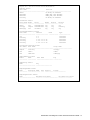
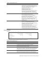
Typographical conventions
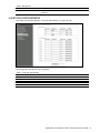
The following table describes the typographic styles used in this guide:
Table 1 Typographic conventions
Typeface or symbol
Meaning
Example
AaBbCc123
This type depicts onscreen computer output and
prompts.
This type displays in command examples and
shows text that must be typed in exactly as
shown.
This italicized type displays in command examples
as a parameter placeholder. Replace the indicated
text with the appropriate real name or value when
using the command. Do not type the brackets.
This also shows guide titles, special terms, or
words to be emphasized.
Command items shown inside brackets are
optional and can be used or excluded as the
situation demands. Do not type the brackets.
Main#
AaBbCc123
<AaBbCc123>
[ ]
Main# sys
To establish a Telnet session, enter:
host# telnet <IP address>
Read the user guide thoroughly.
host# ls [-a]
N8406-022A 1Gb Intelligent L2 Switch Smart Panel Reference Guide
5
Management Network
The 1Gb Intelligent L2 Switch is a Switch Module within the Blade Enclosure. The Blade Enclosure includes an
Enclosure Manager Card which manages the modules and CPU Blades in the enclosure.
The 1Gb Intelligent L2 Switch communicates with the Enclosure Manager Card through its internal management
port (port 19). The factory default settings permit management and control access to the switch through the 10/100
Mbps Ethernet port on the Blade Enclosure, or the built-in console port.
The switch management network has the following characteristics:
Port 19 — Management port 19 has the following configuration:
Flow control: both
Auto-negotiation
Untagged
Port VLAN ID (PVID): 4095
VLAN 4095 — Management VLAN 4095 isolates management traffic within the switch. VLAN 4095 contains
only one member port (port 19). No other ports can be members of VLAN 4095.
Interface 256 — Management interface 256 is associated with VLAN 4095. No other interfaces can be
associated with VLAN 4095. The IP address of the management interface is assigned through Dynamic Host
Control Protocol (DHCP).
Gateway 4 — This gateway is the default gateway for the management interface.
Connecting to the switch
You can access the command line interface in one of the following ways:
Using a console connection via the console port
Using a Telnet connection over the network
Using a Secure Shell (SSH) connection to securely log in over a network
Using a HTTP connection over the network
Establishing a console connection
To establish a console connection with the switch, you need:
A null modem cable with a female DB-9 connector (See the User’s Guide for more information.)
An ASCII terminal or a computer running terminal emulation software set to the parameters shown in the table
below
Table 2 Console configuration parameters
Parameter
Value
Baud Rate
Data Bits
Parity
Stop Bits
Flow Control
9600
8
None
1
None
To establish a console connection with the switch:
1.
Connect the terminal to the console port using the null modem cable.
2.
Power on the terminal.
3.
Press the Enter key a few times on the terminal to establish the connection.
4.
You will be required to enter a password for access to the switch. (For more information, see the “Accessing
the switch” section later in this chapter.)
N8406-022A 1Gb Intelligent L2 Switch Smart Panel Reference Guide
6
Setting an IP address
To access the switch via a Telnet, an SSH connection, or an HTTP connection, you need to have an Internet
Protocol (IP) address set for the switch. You can assign the IP address only to the management interface (interface
256), associated with port 19. The management interface requests its IP address from a Dynamic Host Control
Protocol (DHCP) server on the Enclosure Manager Card. See the User’s Guide of the Enclosure Manager Card for
configuration to assign the IP address to the switch modules.
NOTE: You can assign the IP address only on the management port 19.
Establishing a Telnet connection
A Telnet connection offers the convenience of accessing the switch from any workstation connected to the network.
Telnet provides the same options for user, operator, and administrator access as those available through the
console port. By default, Telnet is enabled on the switch. The switch supports four concurrent Telnet connections.
Once the IP parameters are configured, you can access the CLI using a Telnet connection. To establish a Telnet
connection with the switch, run the Telnet program on the workstation and enter the telnet command, followed by
the switch IP address:
telnet <1Gb Intelligent L2 Switch IP address>
You will then be prompted to enter a password. The password entered determines the access level: administrator,
operator, or user. See the “Accessing the switch” section later in this chapter for description of default passwords.
Establishing an SSH connection
Although a remote network administrator can manage the configuration of a switch via Telnet, this method does not
provide a secure connection. The Secure Shell (SSH) protocol enables you to securely log into the switch over the
network.
As a secure alternative to using Telnet to manage switch configuration, SSH ensures that all data sent over the
network is encrypted and secure. In order to use SSH, you must first configure it on the switch. See the “Secure
Shell Server configuration” section in the “Configuration Menu” chapter for information on how to configure SSH.
Establishing an HTTP connection
By default, HTTP is enabled on the switch. You can configure the switch using the Web browser. For more
information, see the “Browser-based interface” chapter.
Accessing the switch
To enable better switch management and user accountability, the switch provides different levels or classes of user
access. Levels of access to the CLI and Web management functions and screens increase as needed to perform
various switch management tasks. The three levels of access are:
User—User interaction with the switch is completely passive; nothing can be changed on the switch. Users
may display information that has no security or privacy implications, such as switch statistics and current
operational state information.
Operator—Operators can only effect temporary changes on the switch. These changes will be lost when the
switch is rebooted/reset. Operators have access to the switch management features used for daily switch
operations. Because any changes an operator makes are undone by a reset of the switch, operators cannot
severely impact switch operation, but do have access to the Maintenance menu.
Administrator—Only administrators can make permanent changes to the switch configuration, changes that
are persistent across a reboot/reset of the switch. Administrators can access switch functions to configure and
troubleshoot problems on the switch. Because administrators can also make temporary (operator-level)
changes as well, they must be aware of the interactions between temporary and permanent changes.
Access to switch functions is controlled through the use of unique usernames and passwords. Once you are
connected to the switch via the local console, Telnet, or SSH, you are prompted to enter a password. The
password entered determines the access level. The default user names/password for each access level is listed in
the following table. Once you are connected to the switch via HTTP, you are prompted to enter a user account and
password.
NOTE: It is recommended that you change default switch passwords after initial configuration and as
regularly as required under your network security policies. For more information, see the “Setting passwords”
section in the “First-time configuration” chapter.
N8406-022A 1Gb Intelligent L2 Switch Smart Panel Reference Guide
7
Table 3 User access levels
User account
Description and tasks performed
user
The user has no direct responsibility for switch management. He or she can view all
switch status information and statistics, but cannot make any configuration changes to
the switch. The user account is enabled by default, and the default password is user.
The operator manages all functions of the switch. The operator can reset ports or the
entire switch. By default, the operator account is disabled and has no password.
The super user administrator has complete access to all menus, information, and
configuration commands on the switch, including the ability to change both the user
and administrator passwords. The admin account is enabled by default, and the
default password is admin.
oper
admin
NOTE: With the exception of the admin user, setting the password to an empty value can disable access to
each user level.
N8406-022A 1Gb Intelligent L2 Switch Smart Panel Reference Guide
8
Browser-based interface
Introduction
This chapter explains how to access the switch browser-based interface (BBI) for the SmartPanel and configure the
switch.
Requirements
To use the browser-based interface, you need the following:
PC or workstation with network access to the switch
Frame-capable Web-browser software, such as the following:
Netscape Navigator 4.7x or higher
Internet Explorer 6.0x or higher
JavaScript enabled in your Web browser
Web browser setup
Most modern Web browsers work with frames and JavaScript by default, and require no additional set up.
However, you should check your Web browser’s features and configuration to be sure frames and JavaScript are
enabled.
NOTE: JavaScript is not the same as Java™. Be sure that JavaScript is enabled in your Web browser.
Starting the BBI
When the switch and browser setup is complete, follow these steps to launch the BBI:
1.
Start your Web browser.
2.
Enter the switch IP interface address in the Web browser Uniform Resource Locator (URL) field.
For example, if the switch IP interface has a network IP address of 192.168.3.70. Using Internet Explorer, you
could enter the following (for secure BBI access, use https://).
If you do not use the default TCP port number (80) for BBI access, you can include the port number when you
enter the IP address:
N8406-022A 1Gb Intelligent L2 Switch Smart Panel Reference Guide
9
If the switch IP interface address has a name on your local domain name server, you can enter the name
instead. Using Internet Explorer, you can enter the following:
3.
Log in to the switch.
If your switch and browser are properly configured, you will be asked to enter a password.
Enter the account name and password for the switch.
4.
Allow the BBI Dashboard page to load.
When the proper account name and password combination is entered, the BBI Port Group Mapping page is
displayed in the browser viewing area.
NOTE: There may be a slight delay while the Port Group Mapping page is initializing. You should not stop
the browser while loading is in progress.
N8406-022A 1Gb Intelligent L2 Switch Smart Panel Reference Guide
10
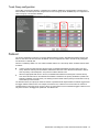
Port Status Area
Menu Area
Configuration Area
There are three main regions on the screen.
The Port Status Area is used to view port status. Click a port icon to view details.
The Menu Area is used to select particular items or features to act upon.
The Configuration Area is used to configure selected items.
Port Status Area
The Status Area contains port icons that display status information about each port. Click a port icon to display
detailed information about the port.
A color box indicates the Port Group in which each port resides.
Table 4 Link status
Color
Green
White
Gray
Description
Link up
No link
Disabled
N8406-022A 1Gb Intelligent L2 Switch Smart Panel Reference Guide
11
Menu Area
The Menu Area is used for selecting a particular feature to act upon. Configuration forms for the selected item
appear in the Configuration Window.
The Menu Area contains a tree of feature folders and names.
Displays I/O
bay number
Click to expand
or contact
Click to select
Click on System Settings to open it and reveal its contents. Click it again to close it. Click on any feature to load the
configuration form in the Configuration Area.
Command Buttons
The following general commands are available at the top of the Menu Area.
Table 5 Menu Area command buttons
Command
Description
Help
Opens a new Web-browser window for displaying the basic online help information. Close
the help browser when finished.
Writes current switch configuration to the screen. Configuration information is displayed with
parameters that have been changed from default values.
Logs off the switch and exits the BBI.
Dump
Logout
Configuration Area
Use the Configuration Area to configure SmartPanel settings.
When a feature is selected from the Menu Area, a configuration form is displayed in the Configuration Area. The
exact nature of the form depends on the type of information available.
Configuration forms display information and allow you to make configuration change to SmartPanel parameters.
Command Buttons
The following general commands are available at the bottom of the Configuration Area.
Table 6 Configuration Area command buttons
Command
Description
Apply
Pending configuration changes do not take effect until you select the Apply command. Once
applied, all changes take effect on the switch immediately. If you do not save the changes,
however, they will be lost the next time the switch is rebooted.
Writes applied configuration changes to non-volatile flash memory on the switch (with the
option of not overlaying the current backup).
Removes pending configuration changes between save commands. Use this command to
restore configuration parameters set since last save command.
Save
Revert Apply
N8406-022A 1Gb Intelligent L2 Switch Smart Panel Reference Guide
12
Port Group Mapping
SmartPanel ports can be combined into Port Groups. Up to five Port Groups are available in the SmartPanel. A
Spare Ports Group is available for unused ports.
VLANs and Link Aggregation Groups (trunks) are configured automatically for each Port Group. No network loops
are allowed in the configuration. All external ports in the Port Group form a trunk group (static trunk or Link
Aggregation Group).
Port Group Characteristics
SmartPanel Port Groups must have the following characteristics.
Each Port Group must contain at least one external port (20-24) and one internal server blade port (1-16).
All external ports in a Port Group must have the same configuration.
Each port in the Port Group is a member of a unique, untagged VLAN.
Tagged VLANs (1-4094) can be assigned to each Port Group. Tagged VLANs cannot be configured across
multiple Port Groups.
All external ports in the Port Group form a trunk group.
NOTE: Cross-connect ports (17-18) are not available in the SmartPanel.
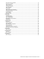
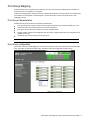
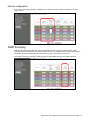
Port Group configuration
On the BBI, choose Port Group Mapping to select the Port Group for each of the external ports and server blade
ports. Click Apply to make the changes active. Click Save to write the configuration to flash memory.
N8406-022A 1Gb Intelligent L2 Switch Smart Panel Reference Guide
13
In this example, Port 1-4, 20-21 are assigned to Group1, and Port 5-8, 22-23 are assigned to Group2. The others
are assigned to Spare Ports Group.
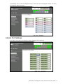
Internal Port Settings
On the BBI, choose Internal Port Settings to enable or disable the server blade port.
N8406-022A 1Gb Intelligent L2 Switch Smart Panel Reference Guide
14
External Port Settings
On the BBI, choose External Port Settings to configure the external port.
The following table describes the external port configuration.
Table 7 External Port Settings
Command
Description
Port Name
Sets a name for the port. The assigned port name appears next to the port
number on some information and statistics screens.
Enables or disables the port.
Sets the link speed. The choices include:
Auto Negotiation Speed and Duplex (default)
1Gbps / Full Duplex
100Mbps / Full Duplex
10Mbps / Full Duplex
Sets the flow control. The choices include:
Rx: Receive flow control
Tx: Transmit flow control
both: Receive and transmit flow control (default)
none: No flow control
Switch Port State
Link configuration
Flow Control
N8406-022A 1Gb Intelligent L2 Switch Smart Panel Reference Guide
15
VLAN
Virtual LANs (VLANs) are commonly used to split up groups of network users into manageable broadcast domains,
to create logical segmentation of workgroups, and to enforce security policies among logical segments. This switch
supports up to 1,000 VLANs per switch. Even though the maximum number of VLANs supported at any given time
is 1,000, each can be identified with any number between 1 and 4095. VLAN 4095 is used by the management
network, which includes the management port 19. VLAN 4095 configuration cannot be modified.
PVID
Each Port Group has a configurable default VLAN number, known as its PVID (Port VLAN ID). All ports are set as
untagged members of PVID. By default, all ports except port 19 are configured as Group1. The PVID of Group1 is 1.
The unique value of PVID is assigned to the Port Group, which contains at least one external port and one internal
server blade port. For the configuration, see the “Port VLAN ID configuration” section later in this chapter.
NOTE: Spare Ports Group for unused ports is assigned a PVID.
802.1Q VLAN Tagging
802.1Q VLAN tagging provides standards-based VLAN support for Ethernet systems. This standard permits
multiple VLANs to be transmitted over a single Ethernet connection.
Tagging places the VLAN identifier in the frame header of a packet, allowing each port to belong to multiple VLANs.
For the configuration to add the VLAN ID to the Port Group, see the “Non-Default Virtual LANs” section later in this
chapter.
NOTE: The SmartPanel does not permit configuration of tagged VLANs across multiple Ports Groups.
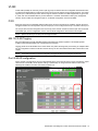
Port VLAN ID configuration
Assign at lease one external port and one internal blade server port to the Port Group to use it and assign a unique
value of PVID. On the BBI, choose System settings > Uplink/Group to change the PVID. Edit the value of the
following Port VLAN ID. The value of unused Port Group is 0.
N8406-022A 1Gb Intelligent L2 Switch Smart Panel Reference Guide
16
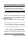
Non-Default Virtual LANs
On the BBI, choose Non-Default Virtual LANs to create VLANs and assign them to Port Groups. The non-default
VLAN ID is placed in the frame header of a packet in forwatding from the port.
The following describes the steps to add VLAN ID.
1.
Click Add VLAN to configure a new VLAN.
2.
Enter a VLAN number and click OK.
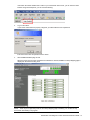
The following is displayed.
N8406-022A 1Gb Intelligent L2 Switch Smart Panel Reference Guide
17
3.
Select the corresponding radio button to assign the VLAN to a Port Group.
4.
Click Apply to make the changes active.
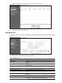
Management
On the BBI, choose System Settings > Management to configure SNMP System Settings and System Log Server
Settings.
The following table describes the management configuration.
Table 8 Management
Command
SNMP System Settings
System Name
System Contact
System Location
System Log Server Settings
IP Address of Primary Server
Severity of Primary Server
Facility of Primary Server
IP Address of Secondary Server
Severity of Secondary Server
Description
Configures the name for the system. The name can have a maximum of 64
characters.
Configures the name of the system contact. The contact can have a maximum
of 64 characters.
Configures the name of the system location. The location can have a maximum
of 64 characters.
Sets the IP address of the primary syslog server.
This option sets the severity level of the primary syslog server displayed. The
default is 7, which means log all the seven severity levels.
This option sets the facility level of the primary syslog server displayed. The
default is 0.
Sets the IP address of the secondary syslog server.
This option sets the severity level of the secondary syslog server displayed.
The default is 7, which means, log all seven severity levels.
N8406-022A 1Gb Intelligent L2 Switch Smart Panel Reference Guide
18
Table 8 Management
Command
Description
Facility of Secondary Server
This option sets the facility level of the secondary syslog server displayed. The
default is 0.
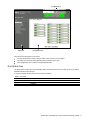
Local User Administration
On the BBI, choose System Settings > Local User Administration to configure the user.
The following table describes the user configuration.
Table 9 Local User Administration
Command
Description
Username
Password
User Type
Enabled
Eject user
Defines the user name of maximum eight characters.
Sets the user password of up to 128 characters maximum.
Sets the Class-of-Service to define the user’s authority level.
Enables or disables the user.
Eject the specified user to access the switch.
N8406-022A 1Gb Intelligent L2 Switch Smart Panel Reference Guide
19
Remote User Administration
On the BBI, choose System Settings > Remote User Administration to configure the RADIUS server or the
TACACS+ server.
The following table describes the configuration.
Table 10 Remote User Administration
Command
Radius
Radius disable/enable
Port
Radius Primary Server
Radius Secret for Primary Server
Radius Secondary Server
Radius Secret for Secondary Server
Tacacs+
Tacacs+ disable/enable
Port
Tacacs+ Primary Server
Tacacs+ Secret for Primary Server
Tacacs+ Secondary Server
Tacacs+ Secret for Secondary Server
Description
Enables or disables the Radius server.
Configures the number of the UDP port to be configured, between 1500 - 3000.
The default is 1645.
Configures the primary Radius server address.
Defines the shared secret (up to 32 characters) between the switch and the
RADIUS server(s).
Configures the secondary Radius server address.
Defines the secondary shared secret (up to 32 characters) between the switch
and the Radius server(s).
Enables or disables the Tacacs+ server.
Configures the number of the TCP port to be configured, between 1 and
65000. The default is 49.
Configures the primary TACACS+ server address.
Configures the shared secret (up to 32 characters) between the switch and the
TACACS+ server.
Configures the secondary TACACS+ server address.
Configures the secondary shared secret (up to 32 characters) between the
switch and the TACACS+ server.
N8406-022A 1Gb Intelligent L2 Switch Smart Panel Reference Guide
20
Time Services
On the BBI, choose System Settings > Time Services to configure the NTP server.
The following table describes the configuration.
Table 11 Time Services
Command
General Settings
Current Date
Current Time
Timezone Location
Daylight Savings
NTP Settings
Time Services
Update Internal (min)
Primary Server
Secondary Server
Description
Configures the system date.
Configures the system time using a 24-hour clock format.
Configures the time zone where the switch resides. You are prompted to select
your location (continent, country, region) by the timezone wizard. Once a
region is selected, the switch updates the time to reflect local changes to
Daylight Savings Time, etc.
Disables or enables daylight savings time in the system clock. When enabled,
the switch will add an extra hour to the system clock so that it is consistent with
the local clock. By default, this option is disabled.
Enables or disables the NTP synchronization service.
Specifies the interval, that is, how often, in minutes (1-44640), to
re-synchronize the switch clock with the NTP server.
Configures the IP address of the primary NTP server to which you want to
synchronize the switch clock.
Configures the IP address of the secondary NTP server to which you want to
synchronize the switch clock.
N8406-022A 1Gb Intelligent L2 Switch Smart Panel Reference Guide
21
Trunking
Trunk groups provide super-bandwidth, multi-link connections between SmartPanel or other trunk-capable devices.
A trunk group is a group of ports that act together, combining their bandwidth to create a single, larger virtual link.
SmartPanel trunk groups are static link aggregation groups that are compatible with Cisco’s EtherChannel
technology.
The SmartPanel is statically configured to place each Port Group into a separate trunk group.
NOTE: Because all ports in a Port Group belong to the same trunk group, individual external ports cannot be
used as a regular 802.3 link. Do not plug a workstation directly into one of the SmartPanel’s external ports,
unless that is the only device plugged into the ports.
When using port trunk groups between the SmartPanel and a switch, you can create a virtual link, operating at up
to 5 Gigabits per second, depending on how many physical ports are combined.
Statistical Load Distribution
Network traffic is statistically distributed between ports in a trunk group. The SmartPanel uses the source and
destination IP address information present in each transmitted IP frame to determine load distribution. If the frame
is not an IP frame, then Layer 2 MAC addresses are used.
Each packet’s particular combination of source and destination addresses results in selecting one line in the trunk
group for data transmission. If there are enough devices feeding the trunk lines, then traffic distribution becomes
relatively even.
Built-In Fault Tolerance
Since trunk groups are comprised of multiple physical links, each trunk group is inherently fault tolerant. As long as
one connection is available, the trunk remains active.
Statistical load balancing is maintained whenever a port in a trunk group is lost or returned to service.
Trunk group configuration rules
The trunking feature operates according to specific configuration rules. When working with trunks, consider the
following rules that determine how a trunk group reacts in any network topology.
All trunks must originate from one device, and lead to one destination device.
Trunking from third-party devices must comply with Cisco® EtherChannel® technology.
All external ports in a Port Group must have the same configuration.
Only external ports in a Port Group are trunked. For Port Group configuration, see the “Port Group
configuration”.
Link Aggregation Control Protocol
Link Aggregation Control Protocol (LACP) is an IEEE 802.3ad standard for grouping several physical ports into one
logical port (known as a dynamic trunk group or Link Aggregation Group) with any device that supports the
standard. Please refer to IEEE 802.3ad-2002 for a full description of the standard.
The 802.3ad standard allows standard Ethernet links to form a single Layer 2 link using the Link Aggregation
Control Protocol (LACP). Link aggregation is a method of grouping physical link segments of the same media type
and speed in full duplex, and treating them as if they were part of a single, logical link segment. If a link in a LACP
trunk group fails, traffic is reassigned dynamically to the remaining link/s of the dynamic trunk group.
N8406-022A 1Gb Intelligent L2 Switch Smart Panel Reference Guide
22
Trunk Group configuration
On the BBI, choose System Settings > Uplink/Group to enable or disable the Link Aggregation Control Protocol.
When enabled, the external ports are configured as a LACP trunk group. When disabled, they are configured as a
static trunk group. The default is disabled.
Failover
The primary application for Failover is to support Network Adapter Teaming. With Network Adapter Teaming, the
NICs on each server all share the same IP address, and are configured into a team. One NIC is the primary link,
and the other is a standby link.
Failover is enabled by default. You can enable or disable Failover on a Port Group. When enabled, Failover works
as follows.
If some (or all) of the links fail in the failover trigger, the SmartPanel disables all internal ports of the Port
Group. When the internal ports are disabled, it causes the NIC team on the affected server blade to failover
from the primary to the backup NIC. This process is called a failover event.
When the appropriate links return to service, the SmartPanel enables the internal ports of the Port Group.
This causes the NIC team on the affected server blades to fail back to the primary SmartPanel (unless AutoFallback is disabled on the NIC team). The backup processes traffic until the primary’s internal links come up,
which takes up to five seconds.
The failover limit lets you specify the minimum number of operational links required within the failover trigger before
the trigger initiates a failover event. For example, if the limit is four, a failover event occurs when the number of
operational links in the trigger is four or fewer. When you set the limit to all, the SmartPanel triggers a failover event
only when no links in the trigger are operational. The default is all.
N8406-022A 1Gb Intelligent L2 Switch Smart Panel Reference Guide
23
Failover configuration
On the BBI, choose System Settings > Uplink/Group to configure the Switch Failover and Number of Links to
Trigger Failover.
IGMP Snooping
IGMP Snooping allows the SmartPanel to forward multicast traffic only to those ports that request it. IGMP
Snooping prevents multicast traffic from being flooded to all ports. The SmartPanel learns which server hosts are
interested in receiving multicast traffic, and forwards it only to ports connected to those servers.
On the BBI, choose System Settings > IGMP Snooping to enable IGMP Snooping. The default is disabled.
N8406-022A 1Gb Intelligent L2 Switch Smart Panel Reference Guide
24
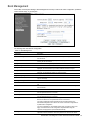
Boot Management
On the BBI, choose System Settings > Boot Management to backup or restore the switch configuration, update the
switch software image, or get dump file.
The following table describes the configuration.
Table 12 Boot Management
Command
Description
Reboot the Module button
Next boot config block
Reboots the switch.
Selects the Configuration Block file (active, backup or factory) that will run after
the next reboot.
Selects which software image (image1 or image2) you want to run in switch
memory for the next reboot.
Selects a software image to replace with the downloaded software.
Image to boot
Image to transfer
Current Image Information
Image 1
Image 2
Boot kernel
Update Image/Cfg
Method to use for transfer
Settings for using FTP or TFTP Server
Server Address
Remote File Name
Button
Get Image
Put Image
Get Cfg
Put Cfg
Displays information about the current Image 1 software. When NormalPanel is
displayed, the conventional Layer 2 switch software is stored in Image1.
Displays information about the current Image 2 software. When SmartPanel is
displayed, the SmartPanel software is stored in Image2.
Displays the version number of the current Boot software.
Select the method to use for transfer (TFTP, FTP or HTTP). HTTP is available
only for Get Image.
Enter the IP address of the TFTP or FTP server from which you will transfer the
file.
Enter the name of the file on a TFTP or FTP server that contains the file you
want to transfer.
Starts download of the software image file indicated in Remote File Name field
from the specified TFTP or FTP server.
Starts upload of the software image file indicated in Remote File Name field
from the specified TFTP or FTP server.
Downloads a previously saved switch Configuration Block file indicated in
Remote File Name from the specified the TFTP or FTP server.
The active configuration will be replaced with the commands found in the
downloaded configuration file. The file can contain a full switch configuration or
a partial switch configuration.
The new configuration is not activated until the apply command is used. If the
apply command is found in the configuration script file loaded using this
command, the apply action is performed automatically.
Uploads the switch’s active configuration to the script configuration file
specified in Remote File Name. The file is placed on the TFTP or FTP server.
N8406-022A 1Gb Intelligent L2 Switch Smart Panel Reference Guide
25
Table 12 Boot Management
Command
Description
Put TS Dump
Uploads the TS (tech support) dump file to the TFTP or FTP server specified in
Remote File Name.
Uploads the core (PANIC) dump file to the TFTP or FTP server specified in
Remote Filename.
Deletes the core dump in flash memory.
Put Crash Dump
Clear Crash Dump
IMPORTANT:
When the switch software is changed (NormalPanel or SmartPanel) and the switch is
rebooted, the switch configuration is removed and the switch runs factory configuration block. Backup the
switch configuration if needed.
N8406-022A 1Gb Intelligent L2 Switch Smart Panel Reference Guide
26
Command Line Interface
Introduction
The CLI is used for viewing switch information and statistics. In addition, the administrator can use the CLI for
performing all levels of switch configuration.
To make the CLI easy to use, the various commands have been logically grouped into a series of menus and
submenus. Each menu displays a list of commands and/or submenus that are available, along with a summary of
what each command will do. Below each menu is a prompt where you can enter any command appropriate to the
current menu.
This chapter describes the Main Menu commands, and provides a list of commands and shortcuts that are
commonly available from all the menus within the CLI.
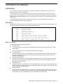
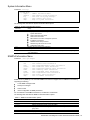
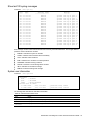
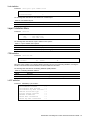
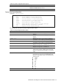
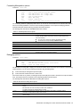
Main Menu
The Main Menu displays after a successful connection and login. The following table shows the Main Menu for the
administrator login. Some features are not available under the user login.
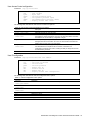
[Main Menu]
info
stats
cfg
oper
boot
maint
diff
apply
save
revert
exit
-
Information Menu
Statistics Menu
Configuration Menu
Operations Command Menu
Boot Options Menu
Maintenance Menu
Show pending config changes [global command]
Apply pending config changes [global command]
Save updated config to FLASH [global command]
Revert pending or applied changes [global command]
Exit [global command, always available]
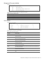
Menu summary
The Main Menu displays the following submenus:
Information Menu
The Information Menu provides submenus for displaying information about the current status of the switch.
Statistics Menu
This menu provides submenus for displaying switch performance statistics.
Configuration Menu
This menu is available only from an administrator login. It includes submenus for configuring every aspect of
the switch. Changes to configuration are not active until explicitly applied. Changes can be saved to nonvolatile memory (NVRAM).
Operations Command Menu
Operations-level commands are used for making immediate and temporary changes to switch configuration.
This menu is used for bringing ports temporarily in and out of service. This menu is available only from an
administrator and operator login.
Boot Options Menu
The Boot Options Menu is available only from an administrator login. This menu is used for upgrading switch
software, selecting configuration blocks, and for resetting the switch when necessary. This menu is also used
to set the switch back to factory settings.
Maintenance Menu
This menu is used for debugging purposes, enabling you to generate a technical support dump of the critical
state information in the switch, and to clear entries in the Forwarding Database and the Address Resolution
Protocol (ARP). This menu is available only from an administrator and operator login.
N8406-022A 1Gb Intelligent L2 Switch Smart Panel Reference Guide
27
Global commands
Some basic commands are recognized throughout the menu hierarchy. These commands are useful for obtaining
online Help, navigating through menus, and for applying and saving configuration changes.
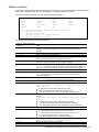
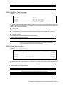
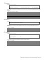
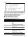
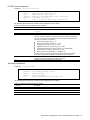
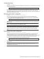
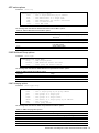
For help on a specific command, type help. The following screen displays:
Global Commands: [can be issued from any menu]
help
up
print
lines
verbose
exit
diff
apply
save
ping
traceroute
telnet
pushd
popd
who
pwd
quit
revert
history
The following are used to navigate the menu structure:
. Print current menu
.. Move up one menu level
/ Top menu if first, or command separator
! Execute command from history
The following table describes the global commands.
Table 13 Global commands
Command
Action
? command or help
Provides usage information about a specific command on the current menu. When
used without the command parameter, a summary of the global commands is
displayed.
Displays the current menu.
Moves up one level in the menu structure.
If placed at the beginning of a command, displays the Main Menu. Otherwise, this is
used to separate multiple commands placed on the same line.
Sets the number of lines (n) that display on the screen at one time. The default is 24
lines. When used without a value, the current setting is displayed.
Shows any pending configuration changes that have not been applied.
diff flash displays all pending configuration changes that have been applied but
not saved to flash memory (NVRAM), as well as those that have not been applied.
Applies pending configuration changes.
Saves the active configuration to backup, and saves the current configuration as active.
save n saves the current configuration as active, without saving the active
configuration to backup.
Removes changes that have been made, but not applied.
revert apply removes all changes that have not been saved.
Exits from the command line interface and logs out.
Verifies station-to-station connectivity across the network. The format is:
. or print
.. or up
/
lines
diff
apply
save
revert
exit or quit
ping
ping <host name> | <IP address> [ <number of tries> [
<msec delay> ]]
traceroute
IP address is the hostname or IP address of the device.
number of tries (optional) is the number of attempts (1-32).
msec delay (optional) is the number of milliseconds between attempts.
Identifies the route used for station-to-station connectivity across the network. The
format is:
traceroute <host name> | <IP address> [<max-hops> [ <msec
delay> ]]
pwd
verbose n
telnet
IP address is the hostname or IP address of the target station.
max-hops (optional) is the maximum distance to trace (1-16 devices)
msec delay (optional) is the number of milliseconds to wait for the response.
Displays the command path used to reach the current menu.
Sets the level of information displayed on the screen:
0 = Quiet: Nothing displays except errors, not even prompts.
1 = Normal: Prompts and requested output are shown, but no menus.
2 = Verbose: Everything is shown. This is the default.
When used without a value, the current setting is displayed.
This command is used to Telnet out of the switch. The format is:
telnet <hostname> | <IP address> [port]
history
pushd
Displays the history of the last ten commands.
Remembers the current location in the directory of menu commands.
N8406-022A 1Gb Intelligent L2 Switch Smart Panel Reference Guide
28
Table 13 Global commands
Command
Action
popd
who
Returns to the last pushd location.
Displays users who are logged in.
Command line history and editing
Using the command line interface, you can retrieve and modify previously entered commands with just a few
keystrokes. The following options are available globally at the command line:
Table 14 Command line history and editing options
Option
Description
history
!!
!n
<Ctrl-p> or
Displays a numbered list of the last ten previously entered commands.
Repeats the last entered command.
Repeats the nth command shown on the history list.
Recalls the previous command from the history list. This can be used multiple times to work
backward through the last ten commands. The recalled command can be entered as is, or
edited using the options below.
Recalls the next command from the history list. This can be used multiple times to work
forward through the last ten commands. The recalled command can be entered as is, or
edited using the options below.
Moves the cursor to the beginning of the command line.
Moves cursor to the end of the command line.
Moves the cursor back one position to the left.
Up arrow key
<Ctrl-n> or
Down arrow key
<Ctrl-a>
<Ctrl-e>
<Ctrl-b> or
Left arrow key
<Ctrl-f> or
Right arrow key
Moves the cursor forward one position to the right.
<Backspace> or Delete
Erases one character to the left of the cursor position.
key
<Ctrl-d>
<Ctrl-k>
<Ctrl-l>
<Ctrl-u>
Other keys
.
..
Deletes one character at the cursor position.
Erases all characters from the cursor position to the end of the command line.
Redisplays the current line.
Clears the entire line.
Inserts new characters at the cursor position.
Prints the current level menu list.
Moves to the previous directory level.
N8406-022A 1Gb Intelligent L2 Switch Smart Panel Reference Guide
29
Command line interface shortcuts
The following shortcuts allow you to enter commands quickly and easily.
Command stacking
As a shortcut, you can type multiple commands on a single line, separated by forward slashes (/). You can connect
as many commands as required to access the menu option that you want.
For example, the keyboard shortcut to access the Simple Network Management Protocol (SNMP) Configuration
Menu from the Main# prompt is:
Main# cfg/sys/ssnmp/name
Command abbreviation
Most commands can be abbreviated by entering the first characters that distinguish the command from the others
in the same menu or submenu.
For example, the command shown above could also be entered as:
Main# c/sys/ssn/n
Tab completion
By entering the first letter of a command at any menu prompt and pressing the Tab key, the CLI will display all
commands or options in that menu that begin with that letter. Entering additional letters will further refine the list of
commands or options displayed.
If only one command fits the input text when the Tab key is pressed, that command will be supplied on the
command line, waiting to be entered. If the Tab key is pressed without any input on the command line, the currently
active menu displays.
N8406-022A 1Gb Intelligent L2 Switch Smart Panel Reference Guide
30
Information Menu
Introduction
You can view configuration information for the switch in the user, operator, and administrator command modes.
This chapter discusses how to use the CLI to display switch information.
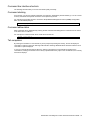
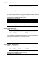
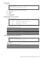
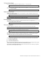
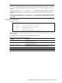
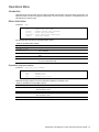
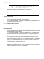
Menu overview
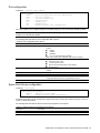
Command: /info
[Information Menu]
sys
- System Information Menu
l2
- Layer 2 Information Menu
l3
- Layer 3 Information Menu
link
- Show link status
port
- Show port information
group
- Show group information
dump
- Dump all information
The following table describes the Information Menu options.
Table 15 Information Menu options
Command
Usage
sys
l2
l3
link
Displays system information.
Displays the Layer 2 Information Menu.
Displays the Layer 3 Information Menu.
Displays configuration information about each port, including:
Port number
Port speed (10 Mb/s, 100 Mb/s, 1000 Mb/s, or any)
Duplex mode (half, full, or any)
Flow control for transmit and receive (no, yes, or any)
Link status (up or down)
Displays port status information, including:
Port number
Port name
VLAN membership
Displays the group information
Dumps all switch information available from the Information Menu (10K or more, depending on
your configuration).
If you want to capture dump data to a file, set your communication software on your workstation
to capture session data prior to issuing the dump commands.
port
group
dump
N8406-022A 1Gb Intelligent L2 Switch Smart Panel Reference Guide
31
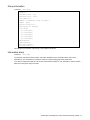
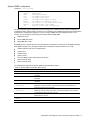
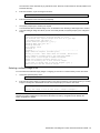
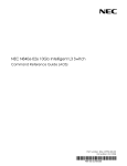
System Information Menu
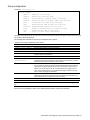
Command: /info/sys
[System Menu]
snmpv3
general
log
user
dump
-
SNMPv3 Information Menu
Show general system information
Show last 100 syslog messages
Show current user status
Dump all system information
The following table describes the System Information Menu options.
Table 16 System Information Menu options
Command
Usage
snmpv3
general
Displays the SNMP v3 Menu.
Displays system information, including:
System date and time
Switch model name and number
Switch name and location
MAC address of the switch management processor
IP address of IP interface
Hardware version and part number
Software image file and version number
Configuration block name
Displays 100 most recent syslog messages.
Displays the User Access Information Menu.
Dumps all switch information available from the Information Menu (10K or more, depending on
your configuration).
log
user
dump
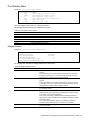
SNMPv3 Information Menu
Command: /info/sys/snmpv3
[SNMPv3 Information Menu]
usm
- Show usmUser table information
view
- Show vacmViewTreeFamily table information
access
- Show vacmAccess table information
group
- Show vacmSecurityToGroup table information
comm
- Show community table information
taddr
- Show targetAddr table information
tparam
- Show targetParams table information
notify
- Show notify table information
dump
- Show all SNMPv3 information
SNMP version 3 (SNMPv3) is an extensible SNMP Framework that supplements the SNMPv2 Framework by
supporting the following:
a new SNMP message format
security for messages
access control
remote configuration of SNMP parameters
For more details on the SNMPv3 architecture, see RFC2271 to RFC2276.
The following table describes the SNMPv3 Information Menu options.
Table 17 SNMPv3 Information Menu options
Command
Usage
usm
view
access
group
Displays User Security Model (USM) table information.
Displays information about view name, subtrees, mask and type of view.
Displays View-based Access Control information.
Displays information about the group that includes the security model, user name, and
group name.
Displays information about the community table.
Displays the Target Address table.
comm
taddr
N8406-022A 1Gb Intelligent L2 Switch Smart Panel Reference Guide
32
Table 17 SNMPv3 Information Menu options
Command
Usage
tparam
notify
dump
Displays the Target parameters table.
Displays the Notify table.
Displays all the SNMPv3 information.
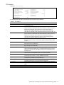
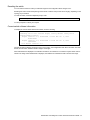
SNMPv3 USM User Table information
Command: /info/sys/snmpv3/usm
usmUser Table:
User Name
-------------------------------adminmd5
adminsha
v1v2only
Protocol
-------------------------------HMAC_MD5, DES PRIVACY
HMAC_SHA, DES PRIVACY
NO AUTH, NO PRIVACY
The User-based Security Model (USM) in SNMPv3 provides security services such as authentication and privacy of
messages. This security model makes use of a defined set of user identities displayed in the USM user table. The
USM user table contains information like:
the user name
a security name in the form of a string whose format is independent of the Security Model
an authentication protocol, which is an indication that the messages sent on behalf of the user can be
authenticated
the privacy protocol
The following table describes the SNMPv3 User Table information.
Table 18 SNMPv3 User Table parameters
Field
Description
User Name
Protocol
This is a string that represents the name of the user that you can use to access the switch.
This indicates whether messages sent on behalf of this user are protected from disclosure using
a privacy protocol. switch software supports DES algorithm for privacy. The software also
supports two authentication algorithms: MD5 and HMAC-SHA.
SNMPv3 View Table information
Command: /info/sys/snmpv3/view
View Name
Subtree
------------------ ---------------------------iso
1
v1v2only
1
v1v2only
1.3.6.1.6.3.15
v1v2only
1.3.6.1.6.3.16
v1v2only
1.3.6.1.6.3.18
Mask
-------------
Type
-------included
included
excluded
excluded
excluded
The user can control and restrict the access allowed to a group to only a subset of the management information in
the management domain that the group can access within each context by specifying the group’s rights in terms of
a particular MIB view for security reasons.
The following table describes the SNMPv3 View Table information.
Table 19 SNMPv3 View Table parameters
Field
Description
View Name
Subtree
Displays the name of the view.
Displays the MIB subtree as an OID string. A view subtree is the set of all MIB object
instances which have a common Object Identifier prefix to their names.
Displays the bit mask.
Displays whether a family of view subtrees is included or excluded from the MIB view.
Mask
Type
N8406-022A 1Gb Intelligent L2 Switch Smart Panel Reference Guide
33
SNMPv3 Access Table information
Command: /info/sys/snmpv3/access
Group Name
---------v1v2grp
admingrp
Model
------snmpv1
usm
Level
-----------noAuthNoPriv
authPriv
ReadV
WriteV
--------- -------iso
iso
iso
iso
NotifyV
------v1v2only
iso
The access control sub system provides authorization services.
The vacmAccessTable maps a group name, security information, a context, and a message type, which could be
the read or write type of operation or notification into a MIB view.
The View-based Access Control Model defines a set of services that an application can use for checking access
rights of a group. This group’s access rights are determined by a read-view, a write-view, and a notify-view. The
read-view represents the set of object instances authorized for the group while reading the objects. The write-view
represents the set of object instances authorized for the group when writing objects. The notify-view represents the
set of object instances authorized for the group when sending a notification.
The following table describes the SNMPv3 Access Table information.
Table 20 SNMPv3 Access Table parameters
Field
Description
Group Name
Model
Level
Displays the name of group.
Displays the security model used, for example, SNMPv1, or SNMPv2 or USM.
Displays the minimum level of security required to gain rights of access. For example,
noAuthNoPriv, authNoPriv, or auth-Priv.
Displays the MIB view to which this entry authorizes the read access.
Displays the MIB view to which this entry authorizes the write access.
Displays the Notify view to which this entry authorizes the notify access.
ReadV
WriteV
NotifyV
SNMPv3 Group Table information
Command: /info/sys/snmpv3/group
Sec Model
---------snmpv1
usm
usm
User Name
----------------------------v1v2only
adminmd5
adminsha
Group Name
------------------------------v1v2grp
admingrp
admingrp
A group is a combination of security model and security name that defines the access rights assigned to all the
security names belonging to that group. The group is identified by a group name.
The following table describes the SNMPv3 Group Table information.
Table 21 SNMPv3 Group Table parameters
Field
Description
Sec Model
User Name
Group Name
Displays the security model used, which is any one of: USM, SNMPv1, SNMPv2, and SNMPv3.
Displays the name for the user.
Displays the access name of the group.
SNMPv3 Community Table information
Command: /info/sys/snmpv3/comm
Index
Name
User Name
Tag
---------- ---------- -------------------- ---------trap1
public
v1v2only
v1v2trap
This command displays the community table information stored in the SNMP engine.
The following table describes the SNMPv3 Community Table information.
Table 22 SNMPv3 Community Table parameters
N8406-022A 1Gb Intelligent L2 Switch Smart Panel Reference Guide
34
Field
Description
Index
Name
User Name
Tag
Displays the unique index value of a row in this table.
Displays the community string, which represents the configuration.
Displays the User Security Model (USM) user name.
Displays the community tag. This tag specifies a set of transport endpoints from which a
command responder application accepts management requests and to which a command
responder application sends an SNMP trap.
SNMPv3 Target Address Table information
Command: /info/sys/snmpv3/taddr
Name
Transport Addr Port Taglist
Params
---------- --------------- ---- ---------- --------------trap1
47.81.25.66
162 v1v2trap
v1v2param
This command displays the SNMPv3 target address table information, which is stored in the SNMP engine.
The following table describes the SNMPv3 Target Address Table information.
Table 23 SNMPv3 Target Address Table parameters
Field
Description
Name
Displays the locally arbitrary, but unique identifier associated with this
snmpTargetAddrEntry.
Displays the transport addresses.
Displays the SNMP UDP port number.
This column contains a list of tag values which are used to select target addresses for a
particular SNMP message.
The value of this object identifies an entry in the snmpTargetParamsTable. The identified
entry contains SNMP parameters to be used when generating messages to be sent to this
transport address.
Transport Addr
Port
Taglist
Params
SNMPv3 Target Parameters Table information
Command: /info/sys/snmpv3/tparam
Name
MP Model User Name
Sec Model Sec Level
------------------- -------- -------------------- --------- ----------v1v2param
snmpv2c v1v2only
snmpv1
noAuthNoPriv
The following table describes the SNMPv3 Target Parameters Table information.
Table 24 SNMPv3 Target Parameters Table
Field
Description
Name
Displays the locally arbitrary, but unique identifier associated with this
snmpTargeParamsEntry.
Displays the Message Processing Model used when generating SNMP messages using
this entry.
Displays the securityName, which identifies the entry on whose behalf SNMP messages
will be generated using this entry.
Displays the security model used when generating SNMP messages using this entry. The
system may choose to return an inconsistentValue error if an attempt is made to set this
variable to a value for a security model which the system does not support.
Displays the level of security used when generating SNMP messages using this entry.
MP Model
User Name
Sec Model
Sec Level
N8406-022A 1Gb Intelligent L2 Switch Smart Panel Reference Guide
35
SNMPv3 Notify Table information
Command: /info/sys/snmpv3/notify
Name
Tag
-------------------- -------------------v1v2trap
v1v2trap
The following table describes the SNMPv3 Notify Table information.
Table 25 SNMPv3 Notify Table
Field
Description
Name
Tag
The locally arbitrary, but unique identifier associated with this snmpNotifyEntry.
This represents a single tag value which is used to select entries in the
snmpTargetAddrTable. Any entry in the snmpTargetAddrTable that contains a tag
value equal to the value of this entry is selected. If this entry contains a value of zero length, no
entries are selected.
SNMPv3 dump
Command: /info/sys/snmpv3/dump
N8406-022A 1Gb Intelligent L2 Switch Smart Panel Reference Guide
36
Engine ID = 80:00:07:50:03:00:0F:6A:F8:EF:00
usmUser Table:
User Name
Protocol
-------------------------------- -------------------------------admin
NO AUTH, NO PRIVACY
adminmd5
HMAC_MD5, DES PRIVACY
adminsha
HMAC_SHA, DES PRIVACY
v1v2only
NO AUTH, NO PRIVACY
vacmAccess
Group Name
---------admin
v1v2grp
admingrp
Table:
Model
------usm
snmpv1
usm
Level
-----------noAuthNoPriv
noAuthNoPriv
authPriv
ReadV
------org
org
org
WriteV
-------org
org
org
vacmViewTreeFamily Table:
View Name
Subtree
Mask
-------------------- --------------- -----------org
1.3
v1v2only
1.3
v1v2only
1.3.6.1.6.3.15
v1v2only
1.3.6.1.6.3.16
v1v2only
1.3.6.1.6.3.18
vacmSecurityToGroup Table:
Sec Model User Name
---------- ------------------------------snmpv1
v1v2only
usm
admin
usm
adminsha
NotifyV
-----org
v1v2only
org
Type
-------------included
included
excluded
excluded
excluded
Group Name
----------------------v1v2grp
admin
admingrp
snmpCommunity Table:
Index
Name
User Name
Tag
---------- ---------- -------------------- ---------snmpNotify Table:
Name
Tag
-------------------- -------------------snmpTargetAddr Table:
Name
Transport Addr Port Taglist
Params
---------- --------------- ---- ---------- --------------snmpTargetParams Table:
Name
MP Model User Name
Sec Model Sec Level
-------------------- -------- ------------------ --------- -------
N8406-022A 1Gb Intelligent L2 Switch Smart Panel Reference Guide
37
System information
Command: /info/sys/gen
System Information at
Time zone: Asia/Tokyo
6:56:22 Thu Jan 11, 2006
Blade Network Technologies 1Gb Intelligent L2 Switch, SmartPanel
sysName:
sysLocation:
RackId: NEC01A 6X00125
RackName: Default_Rack_Name
EnclosureSerialNumber: NEC01A 6X00125
EnclosureName: Default_Chassis_Name
BayNumber: 1
Switch is up 0 days, 14 hours, 56 minutes and 22 seconds.
Last boot: power cycle
MAC address: 00:17:ef:80:7a:00
IP (If 256) address: 10.14.4.16
Revision:
Switch Serial No: MY3644052B
Spare Part No: 856-126690-001-A
Software Version 1.0.0 (FLASH image2), active configuration.
System information includes:
System date and time
Switch model name and number
Rack name and location
MAC address of the switch management processor
IP address of the switch
Software image file and version number
Current configuration block (active, backup, or factory default)
N8406-022A 1Gb Intelligent L2 Switch Smart Panel Reference Guide
38
Show last 100 syslog messages
Command: /info/sys/log
Date
---Jul 8
Jul 8
Jul 8
Jul 8
Jul 8
Jul 8
Jul 8
Jul 8
Jul 8
Jul 8
Jul 8
Jul 8
Jul 8
Jul 8
Jul 8
Jul 8
Jul 8
Jul 8
Jul 8
Jul 8
Time
---17:25:41
17:25:41
17:25:41
17:25:41
17:25:41
17:25:41
17:25:41
17:25:41
17:25:41
17:25:41
17:25:41
17:25:41
17:25:41
17:25:41
17:25:42
17:25:42
17:25:42
17:25:42
17:25:42
17:25:42
Severity level
----------------NOTICE
NOTICE
NOTICE
NOTICE
NOTICE
NOTICE
NOTICE
NOTICE
NOTICE
NOTICE
NOTICE
NOTICE
NOTICE
NOTICE
NOTICE
NOTICE
NOTICE
NOTICE
NOTICE
NOTICE
system:
system:
system:
system:
system:
system:
system:
system:
system:
system:
system:
system:
system:
system:
system:
system:
system:
system:
system:
system:
Message
------link up on
link up on
link up on
link up on
link up on
link up on
link up on
link up on
link up on
link up on
link up on
link up on
link up on
link up on
link up on
link up on
link up on
link up on
link up on
link up on
port
port
port
port
port
port
port
port
port
port
port
port
port
port
port
port
port
port
port
port
1
8
7
12
11
14
13
16
15
17
20
22
23
21
4
3
6
5
10
9
Each message contains a date and time field and has a severity level associated with it. One of eight different
prefixes is used to indicate the condition:
EMERG—indicates the system is unusable
ALERT—indicates action should be taken immediately
CRIT—indicates critical conditions
ERR—indicates error conditions or eroded operations
WARNING—indicates warning conditions
NOTICE—indicates a normal but significant condition
INFO—indicates an information message
DEBUG—indicates a debug-level message
System user information
Command: /info/sys/user
Usernames:
user
- enabled
oper
- disabled
admin
- Always Enabled
Current User ID table:
1: name tech1
, ena, cos user
2: name tech2
, ena, cos user
, password valid, online
, password valid, offline
The following table describes the User Name information.
Table 26 User Name Information menu
Field
Usage
user
oper
admin
Current User
ID Table
Displays the status of the user access level.
Displays the status of the oper (operator) access level.
Displays the status of the admin (administrator) access level.
Displays the status of configured User ID
N8406-022A 1Gb Intelligent L2 Switch Smart Panel Reference Guide
39
Layer 2 information
Command: /info/l2
[Layer 2 Menu]
fdb
- Forwarding Database Information Menu
trunk
- Show Trunk Group information
dump
- Dump all layer 2 information
The following table describes the Layer 2 Information menu options.
Table 27 Layer 2 information menu options
Command
Usage
fdb
trunk
dump
Displays the Forwarding Database Information Menu.
When trunk groups are configured, you can view the state of each port in the various trunk groups.
Dumps all switch information available from the Layer 2 menu (10K or more, depending on your
configuration).
If you want to capture dump data to a file, set your communication software on your workstation to
capture session data prior to issuing the dump commands.
N8406-022A 1Gb Intelligent L2 Switch Smart Panel Reference Guide
40
FDB information menu
Command: /info/l2/fdb
[Forwarding Database Menu]
find
- Show a single FDB entry by MAC address
port
- Show FDB entries on a single port
vlan
- Show FDB entries on a single VLAN
state
- Show FDB entries by state
dump
- Show all FDB entries
The forwarding database (FDB) contains information that maps the media access control (MAC) address of each
known device to the switch port where the device address was learned. The FDB also shows which other ports
have seen frames destined for a particular MAC address.
NOTE: The master forwarding database supports up to 8K MAC address entries on the management
processor (MP) per switch.
Table 28 FDB information menu
Command
Usage
find <MAC address> [<VLAN>]
Displays a single database entry by its MAC address. You are
prompted to enter the MAC address of the device.
Enter the MAC address using the format: xx:xx:xx:xx:xx:xx. (For
example: 08:00:20:12:34:56)
You can also enter the MAC address using the format: xxxxxxxxxxxx.
(For example: 080020123456)
Displays all FDB entries for a particular port.
Displays all FDB entries on a single VLAN. The range is 1-4095.
Displays all FDB entries that match a particular state.
Displays all entries in the Forwarding Database.
port <port number>
vlan <1-4095>
state unknown|forward|trunk
dump
Show all FDB information
Command: /info/l2/fdb/dump
MAC address
----------------00:02:01:00:00:00
00:02:01:00:00:01
00:02:01:00:00:02
00:02:01:00:00:03
00:02:01:00:00:04
00:02:01:00:00:05
00:02:01:00:00:06
00:02:01:00:00:07
00:02:01:00:00:08
00:02:01:00:00:09
00:02:01:00:00:0a
00:02:01:00:00:0b
00:02:01:00:00:0c
VLAN
---300
300
300
300
300
300
300
300
300
300
300
300
300
Port
---23
23
23
23
23
23
23
23
23
23
23
23
Trnk
---1
State
----TRK
FWD
FWD
FWD
FWD
FWD
FWD
FWD
FWD
FWD
FWD
FWD
FWD
An address that is in the forwarding (FWD) state indicates that the switch has learned it. When in the trunking
(TRK) state, the Trnk field displays the trunk group number. If the state for the port is listed as unknown (UNK), the
MAC address has not yet been learned by the switch, but has only been seen as a destination address. When an
address is in the unknown state, no outbound port is indicated.
Clearing entries from the forwarding database
To delete a static MAC address from the forwarding database (FDB), see the “Static FDB configuration” section in
the “Configuration Menu” chapter. To clear the entire forwarding database (FDB), see the “Forwarding Database
options” section in the “Maintenance Menu” chapter.
N8406-022A 1Gb Intelligent L2 Switch Smart Panel Reference Guide
41
Trunk group information
Command: /info/l2/trunk
Trunk group 1, Enabled
Protocol - Static
port state:
20: forwarding
21: forwarding
22: forwarding
23: forwarding
24: forwarding
When trunk groups are configured, you can view the state of each port in the various trunk groups.
Layer 3 information
Command: /info/l3
[Layer 3 Menu]
arp
ip
igmp
dump
-
ARP Information Menu
Show IP information
Show IGMP Snooping Multicast Group information
Dump all layer 3 information
The following table describes the Layer 3 Information Menu options.
Table 29 Layer 3 information menu options
Command
Usage
arp
ip
Displays the Address Resolution Protocol (ARP) Information Menu.
Displays IP Information. IP information, includes:
IP interface information: Interface number, IP address, subnet mask, VLAN number, and
operational status.
Default gateway information: Metric for selecting which configured gateway to use,
gateway number, IP address, and health status
IP forwarding information: Enable status, lnet and lmask
Port status
Displays IGMP Information Menu.
Dumps all switch information available from the Layer 3 Menu (10K or more, depending on
your configuration).
If you want to capture dump data to a file, set your communication software on your
workstation to capture session data prior to issuing the dump commands.
igmp
dump
N8406-022A 1Gb Intelligent L2 Switch Smart Panel Reference Guide
42
ARP information
Command: /info/arp
[Address Resolution Protocol Menu]
find
- Show a single ARP entry by IP address
port
- Show ARP entries on a single port
vlan
- Show ARP entries on a single VLAN
addr
- Show ARP entries for switch's interface
dump
- Show all ARP entries
The Address Resolution Protocol (ARP) information includes IP address and MAC address of each entry, address
status flags, VLAN, and port for the address, and port referencing information.
The following table describes the Address Resolution Protocol Menu options.
Table 30 ARP information
Command
Usage
find <IP address>
port <port number>
vlan <1-4095>
addr
Displays a single ARP entry by IP address. For example, 192.4.17.101
Displays the ARP entries on a single port.
Displays the ARP entries on a single VLAN.
Displays the ARP address list: IP address, IP mask, MAC address, and VLAN
flags.
Displays all ARP entries, including:
IP address and MAC address of each entry
Address status flag
The VLAN and port to which the address belongs
The ports which have referenced the address (empty if no port has routed traffic
to the IP address shown)
dump
ARP address list information
Command: /info/arp/addr
IP address
IP mask
--------------- --------------205.178.18.66
255.255.255.255
MAC address
VLAN
----------------- ---00:70:cf:03:20:04 4095
Show all ARP entry information
Command: /info/arp/dump
IP address
Flags
--------------- ----192.168.2.4
192.168.2.19
192.168.2.61
P
MAC address
----------------00:50:8b:b2:32:cb
00:0e:7f:25:89:b5
00:0f:6a:ed:46:00
VLAN
---4095
4095
4095
Port
---19
19
The Flag field provides additional information about an entry. If no flag displays, the entry is normal.
Table 31 ARP dump flag parameters
Flag
Description
P
R
U
Permanent entry created for switch IP interface.
Indirect route entry.
Unresolved ARP entry. The MAC address has not been learned.
N8406-022A 1Gb Intelligent L2 Switch Smart Panel Reference Guide
43
IP information
Command: /info/l3/ip
Interface information:
1: 47.80.23.243
255.255.254.0
47.80.23.255,
Default gateway information: metric strict
4: 47.80.23.254,
vlan 4095,
up active
vlan 1, up
The following interface and default gateway information is displayed:
Interface number
IP address
IP mask
IP broadcast address
Operational status
IGMP multicast group information
Command: /info/l3/igmp
[IGMP Multicast
mrouter find
vlan
port
trunk
dump
-
Group Menu]
Show IGMP Snooping Multicast Router Port information
Show a single group by IP group address
Show groups on a single vlan
Show groups on a single port
Show groups on a single trunk
Show all groups
The following table describes the commands used to display information about IGMP groups learned by the switch.
Table 32 IGMP Multicast Group menu options
Command
Usage
mrouter
find <IP address>
vlan <1-4094>
port <port number>
trunk <1-40>
dump
Displays the Multicast Router Menu.
Displays a single IGMP multicast group by its IP address.
Displays all IGMP multicast groups on a single VLAN.
Displays all IGMP multicast groups on a single port.
Displays all IGMP multicast groups on a single trunk group.
Displays information for all multicast groups.
IGMP multicast router port information
Command: /info/l3/igmp/mrouter
[IGMP Multicast Router Menu]
vlan - Show all multicast router ports on a single vlan
dump - Show all multicast router ports
The following table describes the commands used to display information about multicast routers learned through
IGMP Snooping.
Table 33 IGMP Multicast Router menu options
Command
Usage
vlan <1-4094>
dump
Displays information for all multicast groups on a single VLAN.
Displays information for all multicast groups learned by the switch.
N8406-022A 1Gb Intelligent L2 Switch Smart Panel Reference Guide
44
Link status information
Command: /info/link
-----------------------------------------------------------------Port
Speed
Duplex
Flow Ctrl
Link
--------------- --TX-----RX------1
1000
full
yes
yes
up
2
1000
full
yes
yes
up
3
1000
full
yes
yes
up
4
1000
full
yes
yes
up
5
any
any
yes
yes
down
6
any
any
yes
yes
down
7
any
any
yes
yes
down
8
any
any
yes
yes
up
9
any
any
yes
yes
down
10
any
any
yes
yes
down
11
any
any
yes
yes
down
12
any
any
yes
yes
down
13
any
any
yes
yes
down
14
any
any
yes
yes
down
15
any
any
yes
yes
down
16
any
any
yes
yes
down
19
100
full
no
no
up
20
1000
full
no
no
up
21
1000
full
no
no
up
22
any
any
any
yes
down
23
any
any
yes
yes
down
24
any
any
yes
yes
down
Use this command to display link status information about each port on a switch, including:
Port number
Port speed (10 Mb/s, 100 Mb/s, 1000 Mb/s, or any)
Duplex mode (half, full, or any)
Flow control for transmit and receive (no or yes)
Link status (up or down)
Port information
Command: /info/port
Port
---1
2
3
4
5
6
7
8
9
10
11
12
13
14
15
16
19
20
21
22
23
24
NAME
-------------Downlink1
Downlink2
Downlink3
Downlink4
Downlink5
Downlink6
Downlink7
Downlink8
Downlink9
Downlink10
Downlink11
Downlink12
Downlink13
Downlink14
Downlink15
Downlink16
Mgmt
Uplink1
Uplink2
Uplink3
Uplink4
Uplink5
VLAN(s)
------------------------------1
1
1
1
1
1
1
1
1
1
1
1
1
1
1
1
4095
1
1
1
1
1
Port information includes:
N8406-022A 1Gb Intelligent L2 Switch Smart Panel Reference Guide
45
Port number
Port name
VLAN membership
N8406-022A 1Gb Intelligent L2 Switch Smart Panel Reference Guide
46
Group information
Command: /info/group
Group 1:
Internal Ports: 1-16
External Ports: 20-24
Port VLAN ID: 1
Number of nondefault vlans in group: 0
VLANs: empty
Default Group Vlan: 1
Trunk group 13: Enabled
port state:
20: forwarding
21: forwarding
22: forwarding
23: forwarding
24: forwarding
LACP Enabled
IGMP Disabled
Failover Enabled
Failover Limit = 0
This displays the information of Port Group 1-5 and Spare Ports Group.
Information dump
Command: /info/dump
Use the dump command to dump all switch information available from the Information Menu (10K or more,
depending on your configuration). This data is useful for tuning and debugging switch performance.
If you want to capture dump data to a file, set the communication software on your workstation to capture session
data prior to issuing the dump commands.
N8406-022A 1Gb Intelligent L2 Switch Smart Panel Reference Guide
47
Statistics Menu
Introduction
You can view switch performance statistics in the user, operator, and administrator command modes. This chapter
discusses how to use the CLI to display switch statistics.
Menu information
Command: /stats
[Statistics Menu]
port
- Port Stats Menu
clrports – Clear stats for all ports
l2
- Layer 2 Stats Menu
l3
- Layer 3 Stats Menu
mp
- MP-specific Stats Menu
ntp
- Show NTP stats
dump
- Dump all stats
The following table describes the Statistics Menu options.
Table 34 Statistics Menu options
Command
Usage
port <port number>
Displays the Port Statistics Menu for the specified port. Use this command to display
traffic statistics on a port-by-port basis. Traffic statistics are included in SNMP
Management Information Base (MIB) objects.
Clears the statistics for all ports.
Displays the Layer 2 Statistics Menu.
Displays the Layer 3 Statistics Menu.
Displays the Management Processor Statistics Menu. Use this command to view
information on how switch management processes and resources are currently being
allocated.
Displays Network Time Protocol (NTP) Statistics.
Add the argument, clear, to clear NTP statistics
Dumps all switch statistics. Use this command to gather data for tuning and debugging
switch performance. If you want to capture dump data to a file, set your communication
software on your workstation to capture session data prior to issuing the dump
command.
clrports
l2
l3
mp
ntp <clear>
dump
N8406-022A 1Gb Intelligent L2 Switch Smart Panel Reference Guide
48
Port Statistics Menu
Command: /stats/port <port number>
[Port Statistics Menu]
brg
- Show bridging ("dot1") stats
ether
- Show Ethernet ("dot3") stats
if
- Show interface ("if") stats
ip
- Show Internet Protocol ("IP") stats
link
- Show link stats
clear
- Clear all port stats
This menu displays traffic statistics on a port-by-port basis.
The following table describes the Port Statistics Menu options:
Table 35 Port Statistics Menu options
Command
Usage
brg
ether
if
ip
link
clear
Displays bridging (“dot1”) statistics for the port.
Displays Ethernet (“dot3”) statistics for the port.
Displays interface statistics for the port.
Displays Internet Protocol statistics for the port.
Displays link statistics for the port.
Clears all the statistics on the port.
Bridging statistics
Command: /stats/port <port number>/brg
Bridging statistics for port 1:
dot1PortInFrames:
dot1PortOutFrames:
dot1PortInDiscards:
dot1TpLearnedEntryDiscards:
dot1StpPortForwardTransitions:
63242584
63277826
0
0
0
The following table describes the bridging statistics for a selected port:
Table 36 Bridging statistics for port
Statistics
Description
dot1PortInFrames
The number of frames that have been received by this port from its
segment.
A frame received on the interface corresponding to this port is counted by
this object, if and only if, it is for a protocol being processed by the local
bridging function, including bridge management frames.
The number of frames that have been transmitted by this port to its
segment.
A frame transmitted on the interface corresponding to this port is counted
by this object, if and only if, it is for a protocol being processed by the local
bridging function, including bridge management frames.
Count of valid frames received which were discarded (that is, filtered) by
the forwarding process.
The total number of Forwarding Database entries, which have been or
would have been learned, but have been discarded due to a lack of space
to store them in the Forwarding Database.
If this counter is increasing, it indicates that the Forwarding Database is
regularly becoming full (a condition which has adverse performance effects
on the sub network).
If this counter has a significant value but is not presently increasing, it
indicates that the problem has been occurring but is not persistent.
The number of times this port has transitioned from the Learning state to
the Forwarding state.
dot1PortOutFrames
dot1PortInDiscards
dot1TpLearnedEntryDiscards
dot1StpPortForwardTransition
s
N8406-022A 1Gb Intelligent L2 Switch Smart Panel Reference Guide
49
Ethernet statistics
Command: /stats/port <port number>/ether
Ethernet statistics for port 1:
dot3StatsAlignmentErrors:
dot3StatsFCSErrors:
dot3StatsSingleCollisionFrames:
dot3StatsMultipleCollisionFrames:
dot3StatsLateCollisions:
dot3StatsExcessiveCollisions:
dot3StatsInternalMacTransmitErrors:
dot3StatsFrameTooLongs:
dot3StatsInternalMacReceiveErrors:
0
0
0
0
0
0
0
0
0
The following table describes the Ethernet statistics for a selected port:
Table 37 Ethernet statistics for port
Statistics
Description
dot3StatsAlignmentErrors
A count of frames received on a particular interface that are not
an integral number of octets in length and do not pass the
Frame Check Sequence (FCS) check.
The count represented by an instance of this object is
incremented when the alignmentError status is returned by the
MAC service to the Logical Link Control (LLC) (or other MAC
user).
Received frames for which multiple error conditions obtained
are, according to the conventions of IEEE 802.3 Layer
Management, counted exclusively according to the error status
presented to the LLC.
A count of frames received on a particular interface that are an
integral number of octets in length but do not pass the Frame
Check Sequence (FCS) check.
The count represented by an instance of this object is
incremented when the frameCheckError status is returned by
the MAC service to the LLC (or other MAC user).
Received frames for which multiple error conditions obtained
are, according to the conventions of IEEE 802.3 Layer
Management, counted exclusively according to the error status
presented to the LLC.
A count of successfully transmitted frames on a particular
interface for which transmission is inhibited by exactly one
collision.
A frame that is counted by an instance of this object is also
counted by the corresponding instance of the ifOutUcastPkts,
ifOutMulticastPkts, or ifOutBroadcastPkts, and is not counted
by the corresponding instance of the
dot3StatsMultipleCollisionFrame object.
A count of successfully transmitted frames on a particular
interface for which transmission is inhibited by more than one
collision.
A frame that is counted by an instance of this object is also
counted by the corresponding instance of either the
ifOutUcastPkts, ifOutMulticastPkts, or ifOutBroadcastPkts, and
is not counted by the corresponding instance of the
dot3StatsSingleCollisionFrames object.
The number of times that a collision is detected on a particular
interface later than 512 bit-times into the transmission of a
packet.
Five hundred and twelve bit-times corresponds to 51.2
microseconds on a 10 Mbit/s system. A (late) collision included
in a count represented by an instance of this object is also
considered as a (generic) collision for purposes of other
collision-related statistics.
A count of frames for which transmission on a particular
interface fails due to excessive collisions.
dot3StatsFCSErrors
dot3StatsSingleCollisionFrames
dot3StatsMultipleCollisionFrames
dot3StatsLateCollisions
dot3StatsExcessiveCollisions
N8406-022A 1Gb Intelligent L2 Switch Smart Panel Reference Guide
50
Table 37 Ethernet statistics for port
Statistics
Description
dot3StatsInternalMacTransmitErrors
A count of frames for which transmission on a particular
interface fails due to an internal MAC sublayer transmit error.
A frame is only counted by an instance of this object if it is not
counted by the corresponding instance of either the
dot3StatsLateCollisions object, the
dot3StatsExcessiveCollisions object, or the
dot3StatsCarrierSenseErrors object.
The precise meaning of the count represented by an instance
of this object is implementation specific. In particular, an
instance of this object may represent a count of transmission
errors on a particular interface that are not otherwise counted.
A count of frames received on a particular interface that
exceeds the maximum permitted frame size.
The count represented by an instance of this object is
incremented when the frameTooLong status is returned by the
MAC service to the LLC (or other MAC user).
Received frames for which multiple error conditions obtained
are, according to the conventions of IEEE 802.3 Layer
Management, counted exclusively according to the error status
presented to the LLC.
A count of frames for which reception on a particular interface
fails due to an internal MAC sublayer receive error.
A frame is only counted by an instance of this object if it is not
counted by the corresponding instance of the
dot3StatsFrameTooLongs object, the dot3StatsAlignmentErrors
object, or the dot3StatsFCSErrors object.
The precise meaning of the count represented by an instance
of this object is implementation specific. In particular, an
instance of this object may represent a count of received errors
on a particular interface that are not otherwise counted.
dot3StatsFrameTooLongs
dot3StatsInternalMacReceiveErrors
Interface statistics
Command: /stats/port <port number>/if
Interface statistics for port 1:
ifHCIn Counters
Octets:
51697080313
UcastPkts:
65356399
BroadcastPkts:
0
MulticastPkts:
0
Discards:
0
Errors:
0
ifHCOut Counters
51721056808
65385714
6516
0
0
21187
The following table describes the interface (IF) statistics for a selected port:
Table 38 Interface statistics for port
Statistics
Description
Octets—IfHCIn
UcastPkts—IfHCIn
The total number of octets received on the interface, including framing characters.
The number of packets, delivered by this sublayer to a higher sublayer, which were
not addressed to a multicast or broadcast address at this sublayer.
The number of packets, delivered by this sublayer to a higher sublayer, which were
addressed to a broadcast address at this sublayer.
The total number of packets, delivered by this sublayer. These are the packets that
higher-level protocols requested to be transmitted, and which were addressed to a
multicast address at this sublayer, including those that were discarded or not sent.
For a MAC layer protocol, this includes both group and functional addresses.
The number of inbound packets which were chosen to be discarded even though no
errors were detected to prevent their being delivered to a higher-layer protocol. One
possible reason for discarding such a packet could be to free up buffer space.
BroadcastPkts—IfHCIn
MulticastPkts—IfHCIn
Discards—IfHCIn
N8406-022A 1Gb Intelligent L2 Switch Smart Panel Reference Guide
51
Table 38 Interface statistics for port
Statistics
Description
Errors—IfHCIn
For packet-oriented interfaces, the number of inbound packets that contained errors
preventing them from being delivered to a higher-layer protocol.
For character-oriented or fixed-length interfaces, the number of inbound
transmission units that contained errors preventing them from being deliverable to a
higher-layer protocol.
The total number of octets transmitted out of the interface, including framing
characters.
The total number of packets that higher-level protocols requested to be transmitted,
and which were not addressed to a multicast or broadcast address at this sublayer,
including those that were discarded or not sent.
The total number of packets that higher-level protocols requested to be transmitted,
and which were addressed to a broadcast address at this sublayer, including those
that were discarded or not sent. This object is a 64-bit version of
ifOutBroadcastPkts.
The total number of packets that higher-level protocols requested to be transmitted,
and which were addressed to a multicast address at this sublayer, including those
that were discarded or not sent.
For a MAC layer protocol, this includes both group and functional addresses. This
object is a 64-bit version of ifOutMulticastPkts.
The number of outbound packets that were chosen to be discarded even though no
errors had been detected to prevent their being transmitted. One possible reason for
discarding such a packet could be to free up buffer space.
For packet-oriented interfaces, the number of outbound packets that could not be
transmitted because of errors.
For character-oriented or fixed-length interfaces, the number of outbound
transmission units that could not be transmitted because of errors.
Octets—IfHCOut
UcastPkts—IfHCOut
BroadcastPkts—IfHCOut
MulticastPkts—IfHCOut
Discards—IfHCOut
Errors—IfHCOut
Internet Protocol (IP) statistics
Command: /stats/port <port number>/ip
GEA IP statistics for port 1:
ipInReceives
:
0
ipInHeaderError:
0
ipInDiscards
:
0
The following table describes the Internet Protocol (IP) statistics for a selected port:
Table 39 IP statistics for port
Statistics
Description
ipInReceives
The total number of input datagrams received from interfaces, including those received in
error.
The number of input datagrams discarded because the IP address in their IP header's
destination field was not a valid address to be received at this entity (the switch).
The number of input IP datagrams for which no problems were encountered to prevent their
continued processing, but which were discarded (for example, for lack of buffer space).
Note that this counter does not include any datagrams discarded while awaiting reassembly.
ipInHeaderError
ipInDiscards
N8406-022A 1Gb Intelligent L2 Switch Smart Panel Reference Guide
52
Link statistics
Command: /stats/port <port number>/link
Link statistics for port 1:
linkStateChange:
2
The following table describes the link statistics for a selected port:
Table 40 Link statistics for port
Statistic
Description
linkStateChange
The total number of link state changes.
Layer 2 statistics Menu
Command: /stats/l2
[Layer 2 Statistics Menu]
fdb
- Show FDB stats
lacp
- Show LACP stats
The following table describes the Layer 2 statistics menu options.
Table 41 Layer 2 statistics menu options
Command
Usage
fdb
lacp
Displays the Forwarding Database statistics.
Displays the Link Aggregation Control Protocol statistics.
FDB statistics
Command: /stats/l2/fdb
FDB statistics:
current:
91
hiwat:
91
This menu option enables you to display statistics regarding the use of the forwarding database, including the
number of current entries and the maximum number of entries ever recorded.
The following table describes the Forwarding Database (FDB) statistics:
Table 42 Forwarding Database statistics
Statistic
Description
current
hiwat
Current number of entries in the Forwarding Database.
Highest number of entries recorded at any given time in the Forwarding Database.
LACP statistics
Command: /stats/l2/lacp <port number>
Valid LACPDUs received
Valid Marker PDUs received
Valid Marker Rsp PDUs received
Unknown version/TLV type
Illegal subtype received
LACPDUs transmitted
Marker PDUs transmitted
Marker Rsp PDUs transmitted
-
0
0
0
0
0
0
0
0
N8406-022A 1Gb Intelligent L2 Switch Smart Panel Reference Guide
53
Layer 3 statistics Menu
Command: /stats/l3
[Layer 3 Statistics Menu]
ip
- Show IP stats
route
- Show route stats
arp
- Show ARP stats
icmp
- Show ICMP stats
tcp
- Show TCP stats
udp
- Show UDP stats
igmp
- Show IGMP stats
clrigmp - Clear IGMP stats
ipclear - Clear IP stats
dump
- Dump layer 3 stats
The following table describes the Layer 3 statistics menu options. Layer 3 functionality is limited in this release.
Table 43 Layer 3 statistics menu options
Command
Usage
ip
route
arp <clear>
Displays IP statistics
Displays route statistics
Displays Address Resolution Protocol (ARP) statistics. Add the
argument, clear, to clear ARP statistics.
Displays ICMP statistics.
Displays Transmission Control Protocol (TCP) statistics. Add the
argument, clear, to clear TCP statistics.
Displays User Datagram Protocol (UDP) statistics. Add the
argument, clear, to clear UDP statistics.
Displays IGMP statistics.
Clears all IGMP statistics for the selected VLANs.
Clears IP statistics. Use this command with caution as it will
delete all the IP statistics.
Displays all Layer 3 statistics.
icmp
tcp
udp
igmp
clrigmp <1-4095>|all
ipclear
dump
IP statistics
Command: /stats/l3/ip
IP statistics:
ipInReceives:
ipInAddrErrors:
ipInUnknownProtos:
ipInDelivers:
ipOutDiscards:
ipDefaultTTL:
36475
905
0
4103
0
255
ipInHdrErrors:
0
ipInDiscards:
ipOutRequests:
0
30974
The following table describes the IP statistics:
Table 44 IP statistics
Statistics
Description
ipInReceives
The total number of input datagrams received from interfaces, including those
received in error.
The number of input datagrams discarded due to errors in their IP headers, including
bad checksums, version number mismatch, other format errors, time-to-live exceeded,
errors discovered in processing their IP options, and so on.
The number of input datagrams discarded because the IP address in their IP header
destination field was not a valid address to be received at this switch. This count
includes invalid addresses (for example, 0.0.0.0) and addresses of unsupported
classes (for example, Class E).
For entities which are not IP gateways and therefore do not forward datagrams, this
counter includes datagrams discarded because the destination address was not a
local address.
The number of locally addressed datagrams received successfully but discarded
because of an unknown or unsupported protocol.
ipInHdrErrors
ipInAddrErrors
ipInUnknownProtos
N8406-022A 1Gb Intelligent L2 Switch Smart Panel Reference Guide
54
Table 44 IP statistics
Statistics
Description
ipInDiscards
The number of input IP datagrams for which no problems were encountered to
prevent their continued processing, but which were discarded (for example, for lack of
buffer space).
This counter does not include any datagrams discarded while awaiting re-assembly.
The total number of input datagrams successfully delivered to IP user-protocols
(including ICMP).
The total number of IP datagrams that local IP user-protocols (including ICMP)
supplied to IP in requests for transmission.
This counter does not include any datagrams counted in ipForwDatagrams.
The number of output IP datagrams for which no problem was encountered to prevent
their transmission to their destination, but which were discarded (for example, for lack
of buffer space).
This counter would include datagrams counted in ipForwDatagrams if any such
packets met this (discretionary) discard criterion.
The default value inserted into the Time-To-Live (TTL) field of the IP header of
datagrams originated at this switch, whenever a TTL value is not supplied by the
transport layer protocol.
ipInDelivers
ipOutRequests
ipOutDiscards
ipDefaultTTL
Route statistics
Command: /stats/l3/route
Route statistics:
ipRoutesCur:
ipRoutesMax:
7
512
ipRoutesHighWater:
7
The following table describes the Route statistics:
Table 45 Route statistics
Statistics
Description
ipRoutesCur
The total number of outstanding routes in the route table.
ipRoutesMax
The maximum number of supported routes.
ipRoutesHighWater
The highest number of routes ever recorded in the route table.
ARP statistics
Command: /stats/l3/arp
ARP statistics:
arpEntriesCur:
arpEntriesMax:
2
2047
arpEntriesHighWater:
4
The following table describes the Address Resolution Protocol (ARP) statistics:
Table 46 ARP statistics
Statistic
Description
arpEntriesCur
arpEntriesMax
arpEntriesHighWater
The total number of outstanding ARP entries in the ARP table.
The maximum number of supported ARP entries.
The highest number of ARP entries ever recorded in the ARP table.
N8406-022A 1Gb Intelligent L2 Switch Smart Panel Reference Guide
55
ICMP statistics
Command: /stats/l3/icmp
ICMP statistics:
icmpInMsgs:
icmpInDestUnreachs:
icmpInParmProbs:
icmpInRedirects:
icmpInEchoReps:
icmpInTimestampReps:
icmpInAddrMaskReps:
icmpOutErrors:
icmpOutTimeExcds:
icmpOutSrcQuenchs:
icmpOutEchos:
icmpOutTimestamps:
icmpOutAddrMasks:
245802
41
0
0
244350
0
0
0
0
0
253777
0
0
icmpInErrors:
icmpInTimeExcds:
icmpInSrcQuenchs:
icmpInEchos:
icmpInTimestamps:
icmpInAddrMasks:
icmpOutMsgs:
icmpOutDestUnreachs:
icmpOutParmProbs:
icmpOutRedirects:
icmpOutEchoReps:
icmpOutTimestampReps:
icmpOutAddrMaskReps:
1393
0
0
18
0
0
253810
15
0
0
18
0
0
The following table describes the Internet Control Messaging Protocol (ICMP) statistics:
Table 47 ICMP statistics
Statistics
Description
icmpInMsgs
The total number of ICMP messages which the switch received. Note that this
counter includes all those counted by icmpInErrors.
The number of ICMP messages which the switch received but determined as
having ICMP specific errors (for example bad ICMP checksums and bad
length).
The number of ICMP Destination Unreachable messages received.
The number of ICMP Time Exceeded messages received.
The number of ICMP Parameter Problem messages received.
The number of ICMP Source Quench (buffer almost full, stop sending data)
messages received.
The number of ICMP Redirect messages received.
The number of ICMP Echo (request) messages received.
The number of ICMP Echo Reply messages received.
The number of ICMP Timestamp (request) messages received.
The number of ICMP Timestamp Reply messages received.
The number of ICMP Address Mask Request messages received.
The number of ICMP Address Mask Reply messages received.
The total number of ICMP messages which this switch attempted to send. Note
that this counter includes all those counted by icmpOutErrors.
The number of ICMP messages that this switch did not send due to problems
discovered within ICMP such as a lack of buffer. This value should not include
errors discovered outside the ICMP layer such as the inability of IP to route the
resultant datagram. In some implementations there may be no types of errors
that contribute to this counter's value.
The number of ICMP Destination Unreachable messages sent.
The number of ICMP Time Exceeded messages sent.
The number of ICMP Parameter Problem messages sent.
The number of ICMP Source Quench (buffer almost full, stop sending data)
messages sent.
The number of ICMP Redirect messages sent.
The number of ICMP Echo (request) messages sent.
The number of ICMP Echo Reply messages sent.
The number of ICMP Timestamp (request) messages sent.
The number of ICMP Timestamp Reply messages sent.
The number of ICMP Address Mask Request messages sent.
The number of ICMP Address Mask Reply messages sent.
icmpInErrors
icmpInDestUnreachs
icmpInTimeExcds
icmpInParmProbs
icmpInSrcQuenchs
icmpInRedirects
icmpInEchos
icmpInEchoReps
icmpInTimestamps
icmpInTimestampReps
icmpInAddrMasks
icmpInAddrMaskReps
icmpOutMsgs
icmpOutErrors
icmpOutDestUnreachs
icmpOutTimeExcds
icmpOutParmProbs
icmpOutSrcQuenchs
icmpOutRedirects
icmpOutEchos
icmpOutEchoReps
icmpOutTimestamps
icmpOutTimestampReps
icmpOutAddrMasks
icmpOutAddrMaskReps
N8406-022A 1Gb Intelligent L2 Switch Smart Panel Reference Guide
56
TCP statistics
Command: /stats/l3/tcp
TCP statistics:
tcpRtoAlgorithm:
tcpRtoMax:
tcpActiveOpens:
tcpAttemptFails:
tcpInSegs:
tcpRetransSegs:
tcpCurBuff:
tcpOutRsts:
4
240000
252214
528
756401
0
0
417
tcpRtoMin:
tcpMaxConn:
tcpPassiveOpens:
tcpEstabResets:
tcpOutSegs:
tcpInErrs:
tcpCurConn:
0
512
7
4
756655
0
3
The following table describes the Transmission Control Protocol (TCP) statistics:
Table 48 TCP statistics
Statistics
Description
tcpRtoAlgorithm
The algorithm used to determine the timeout value used for retransmitting
unacknowledged octets.
The minimum value permitted by a TCP implementation for the retransmission
timeout, measured in milliseconds. More refined semantics for objects of this type
depend upon the algorithm used to determine the retransmission timeout. In
particular, when the timeout algorithm is rsre(3), an object of this type has the
semantics of the LBOUND quantity described in Request For Comments (RFC) 793.
The maximum value permitted by a TCP implementation for the retransmission
timeout, measured in milliseconds. More refined semantics for objects of this type
depend upon the algorithm used to determine the retransmission timeout. In
particular, when the timeout algorithm is rsre(3), an object of this type has the
semantics of the UBOUND quantity described in RFC 793.
The limit on the total number of TCP connections the switch can support. In entities
where the maximum number of connections is dynamic, this object should contain
the value -1.
The number of times TCP connections have made a direct transition to the SYNSENT state from the CLOSED state.
The number of times TCP connections have made a direct transition to the SYNRCVD state from the LISTEN state.
The number of times TCP connections have made a direct transition to the CLOSED
state from either the SYN-SENT state or the SYN-RCVD state, plus the number of
times TCP connections have made a direct transition to the LISTEN state from the
SYN-RCVD state.
The number of times TCP connections have made a direct transition to the CLOSED
state from either the ESTABLISHED state or the CLOSE- WAIT state.
The total number of segments received, including those received in error. This count
includes segments received on currently established connections.
The total number of segments sent, including those on current connections but
excluding those containing only retransmitted octets.
The total number of segments retransmitted, that is, the number of TCP segments
transmitted containing one or more previously transmitted octets.
The total number of segments received in error (for example, bad TCP checksums).
The total number of outstanding memory allocations from heap by TCP protocol
stack.
The total number of outstanding TCP sessions that are currently opened.
The number of TCP segments sent containing the reset (RST) flag.
tcpRtoMin
tcpRtoMax
tcpMaxConn
tcpActiveOpens
tcpPassiveOpens
tcpAttemptFails
tcpEstabResets
tcpInSegs
tcpOutSegs
tcpRetransSegs
tcpInErrs
tcpCurBuff
tcpCurConn
tcpOutRsts
N8406-022A 1Gb Intelligent L2 Switch Smart Panel Reference Guide
57
UDP statistics
Command: /stats/l3/udp
UDP statistics:
udpInDatagrams:
udpInErrors:
54
0
udpOutDatagrams:
udpNoPorts:
43
1578077
The following table describes the User Datagram Protocol (UDP) statistics:
Table 49 UDP statistics
Statistics
Description
udpInDatagrams
udpOutDatagrams
udpInErrors
The total number of UDP datagrams delivered to the switch.
The total number of UDP datagrams sent from this switch.
The number of received UDP datagrams that could not be delivered for reasons
other than the lack of an application at the destination port.
The total number of received UDP datagrams for which there was no application at
the destination port.
udpNoPorts
IGMP Multicast Group statistics
Command: /stats/l3/igmp
Enter VLAN number: (1-4094) 1
-----------------------------------------------------------IGMP Snoop vlan 1 statistics:
-----------------------------------------------------------rxIgmpValidPkts:
0
rxIgmpInvalidPkts:
rxIgmpGenQueries:
0
rxIgmpGrpSpecificQueries:
rxIgmpLeaves:
0
rxIgmpReports:
txIgmpReports:
0
txIgmpGrpSpecificQueries:
txIgmpLeaves:
0
rxIgmpV3CurrentStateRecords:
rxIgmpV3SoruceListChangeRecords:
0
rxIgmpV3FilterChangeRecords:
0
0
0
0
0
0
This menu option enables you to display statistics regarding the use of the IGMP Multicast Groups.
The following table describes the IGMP statistics:
Table 50 IGMP statistics
Statistic
Description
rxIgmpValidPkts
rxIgmpInvalidPkts
rxIgmpGenQueries
rxIgmpGrpSpecificQueries
rxIgmpLeaves
rxIgmpReports
txIgmpReports
txIgmpGrpSpecificQueries
txIgmpLeaves
rxIgmpV3CurrentStaateRec
ords
rxIgmpV3SourceListChange
Records
rxIgmpV3FilterChangeReco
rds
Total number of valid IGMP packets received
Total number of invalid packets received
Total number of General Membership Query packets received
Total number of Membership Query packets received from specific groups
Total number of Leave requests received
Total number of Membership Reports received
Total number of Membership reports transmitted
Total number of Membership Query packets transmitted to specific groups
Total number of Leave messages transmitted
Total number of Current State Record
Total number of Source List Record
Total number of Filter Change Record
N8406-022A 1Gb Intelligent L2 Switch Smart Panel Reference Guide 58
Management Processor statistics
Command: /stats/mp
[MP-specific Statistics Menu]
i2c
- Show i2c stats
pkt
- Show Packet stats
tcb
- Show All TCP control blocks in use
ucb
- Show All UDP control blocks in use
cpu
- Show CPU utilization
The following table describes the MP-specific Statistics Menu options:
Table 51 MP-specific Statistics Menu
Command
Usage
i2c
pkt
tcb
ucb
cpu
Displays i2c statistics.
Displays packet statistics, to check for leads and load.
Displays all Transmission Control Protocol (TCP) control blocks (TCB) that are in use.
Displays all User Datagram Protocol (UDP) control blocks (UCB) that are in use.
Displays CPU utilization for periods of up to 1, 4, and 64 seconds.
Packet statistics
Command: /stats/mp/pkt
Packet counts:
allocs:
mediums:
jumbos:
smalls:
failures:
36692
0
0
0
0
frees:
mediums hi-watermark:
jumbos hi-watermark:
smalls hi-watermark:
36692
3
0
2
The following table describes the packet statistics.
Table 52 MP specific packet statistics
Description
Example statistic
allocs
Total number of packet allocations from the packet buffer pool by the TCP/IP protocol stack.
frees
Total number of times the packet buffers are freed (released) to the packet buffer pool by the
TCP/IP protocol stack.
mediums
Total number of packet allocations with size between 128 to 1536 bytes from the packet
buffer pool by the TCP/IP protocol stack.
mediums hi-watermark
The highest number of packet allocation with size between 128 to 1536 bytes from the packet
buffer pool by the TCP/IP protocol stack.
jumbos
Total number of packet allocations with more than 1536 bytes from the packet buffer pool by
the TCP/IP protocol stack.
jumbos hi-watermark
The highest number of packet allocation with more than 1536 bytes from the packet buffer
pool by the TCP/IP protocol stack.
smalls
Total number of packet allocations with size less than 128 bytes from the packet buffer pool
by the TCP/IP protocol stack.
smalls hi-watermark
The highest number of packet allocation with size less than 128 bytes from the packet buffer
pool by the TCP/IP protocol stack.
failures
Total number of packet allocation failures from the packet buffer pool by the TCP/IP protocol
stack.
N8406-022A 1Gb Intelligent L2 Switch Smart Panel Reference Guide
59
TCP statistics
Command: /stats/mp/tcb
All TCP allocated control blocks:
10ad41e8: 0.0.0.0
0 <=> 0.0.0.0
10ad5790: 47.81.27.5
1171 <=> 47.80.23.243
80
23
listen
established
The following table describes the Transmission Control Protocol (TCP) control block (TCB) statistics shown in this
example:
Table 53 MP specified TCP statistics
Description
Example statistic
Memory
10ad41e8/10ad5790
Destination IP address
Destination port
Source IP
Source port
State
0.0.0.0/47.81.27.5
0/1171
0.0.0.0/47.80.23.243
80/23
listen/established
UDP statistics
Command: /stats/mp/ucb
All UDP allocated control blocks:
161: listen
The following table describes the User Datagram Protocol (UDP) control block (UCB) statistics shown in this
example:
Table 54 UDP statistics
Description
Example Statistic
Control block
State
161
listen
CPU statistics
Command: /stats/mp/cpu
CPU utilization:
cpuUtil1Second:
cpuUtil4Seconds:
cpuUtil64Seconds:
8%
9%
8%
The following table describes the management port CPU utilization statistics:
Table 55 CPU statistics
Statistics
Description
cpuUtil1Second
cpuUtil4Seconds
cpuUtil64Seconds
The utilization of MP CPU over 1 second. This is shown as a percentage.
The utilization of MP CPU over 4 seconds. This is shown as a percentage.
The utilization of MP CPU over 64 seconds. This is shown as a percentage.
N8406-022A 1Gb Intelligent L2 Switch Smart Panel Reference Guide
60
NTP statistics
Command: /stats/ntp
NTP statistics:
Primary Server:
Requests Sent:
Responses Received:
Updates:
Secondary Server:
Requests Sent:
Responses Received:
Updates:
17
17
1
0
0
0
Last update based on response from primary server.
Last update time: 18:04:16 Tue Mar 13, 2006
Current system time: 18:55:49 Tue Mar 13, 2006
The switch uses NTP (Network Timing Protocol) version 3 to synchronize the switch’s internal clock with an atomic
time-calibrated NTP server. With NTP enabled, the switch can accurately update its internal clock to be consistent
with other devices on the network and generates accurate syslogs.
The following table describes the NTP statistics:
Table 56 NTP statistics
Statistics
Description
Primary Server
Requests Sent: The total number of NTP requests the switch sent to the primary
NTP server to synchronize time.
Responses Received: The total number of NTP responses received from the
primary NTP server.
Updates: The total number of times the switch updated its time based on the NTP
responses received from the primary NTP server.
Requests Sent: The total number of NTP requests the switch sent to the
secondary NTP server to synchronize time.
Responses Received: The total number of NTP responses received from the
secondary NTP server.
Updates: The total number of times the switch updated its time based on the NTP
responses received from the secondary NTP server.
Last update of time on the switch based on either primary or secondary NTP
response received.
Secondary Server
Last update based on
response from primary
server
Last update time
Current system time
The time stamp showing the time when the switch was last updated.
The switch system time when the command /stats/ntp was issued.
Statistics dump
Command: /stats/dump
Use the dump command to dump all switch statistics available from the Statistics Menu (40K or more, depending
on your configuration). This data can be used to tune or debug switch performance.
If you want to capture dump data to a file, set your communication software on your workstation to capture session
data prior to issuing the dump commands.
N8406-022A 1Gb Intelligent L2 Switch Smart Panel Reference Guide
61
Configuration Menu
Introduction
The Configuration Menu is only available from an administrator login. It includes submenus for configuring every
aspect of the switch. Changes to configuration are not active until explicitly applied. Changes can be saved to nonvolatile memory (NVRAM).
Menu information
Command: /cfg
[Configuration Menu]
sys
- System-wide Parameter Menu
port
- Port Menu
spgroup - Spare Ports Group Menu
group
- Group Menu
dump
- Dump current configuration to script file
ptcfg
- Backup current configuration to FTP/TFTP server
gtcfg
- Restore current configuration from FTP/TFTP server
The following table describes the Configuration Menu options.
Table 57 Configuration Menu options
Command
Usage
sys
port <port number>
spgroup
group <group number>
dump
ptcfg <server IP address> <filename on
host>
gtcfg <server IP address> <filename on
host>
Displays the System Menu.
Displays the Port Menu.
Displays the Spare Ports Group Menu.
Displays the Group Menu.
Dumps current configuration to a script file.
Backs up current configuration to TFTP or FTP server.
Restores current configuration from TFTP or FTP server.
Viewing, applying, reverting, and saving changes
As you use the configuration menus to set switch parameters, the changes you make do not take effect
immediately. All changes are considered pending until you explicitly apply them. Also, any changes are lost the
next time the switch boots unless the changes are explicitly saved.
While configuration changes are in the pending state, you can:
View the pending changes
Apply the pending changes
Revert to restore configuration parameters set with the last apply command
Save the changes to flash memory
N8406-022A 1Gb Intelligent L2 Switch Smart Panel Reference Guide 62
Viewing pending changes
You can view all pending configuration changes by entering diff at any CLI prompt:
# diff
You can view all pending configuration changes that have been applied but not saved to flash memory by entering
diff flash at any CLI prompt:
# diff flash
Applying pending changes
To make your configuration changes active, you must apply them. To apply configuration changes, enter the
following command at any prompt:
# apply
NOTE: All configuration changes take effect immediately when applied.
Reverting changes
The revert command removes configuration changes that have been made, but not applied. Enter revert apply
to remove all changes that have not been saved:
# revert
Saving the configuration
In addition to applying the configuration changes, you can save them to flash memory on the switch.
IMPORTANT:
If you do not save the changes, they will be lost the next time the system is rebooted.
To save the new configuration, enter the following command at any prompt:
# save
When you save configuration changes, the changes are saved to the active configuration block. The configuration
being replaced by the save is first copied to the backup configuration block. If you do not want the previous
configuration block copied to the backup configuration block, enter the following instead:
# save n
You can decide which configuration you want to run the next time you reset the switch. Your options include:
The active configuration block
The backup configuration block
Factory default configuration block
You can view all pending configuration changes that have been applied but not saved to flash memory using the
diff flash command. It is a global command that can be executed from any prompt.
For instructions on selecting the configuration to run at the next system reset, see the “Selecting a configuration
block” section in the “Boot Options Menu” chapter.
N8406-022A 1Gb Intelligent L2 Switch Smart Panel Reference Guide
63
System configuration
Command: /cfg/sys
[System Menu]
syslog
sshd
radius
tacacs+
ntp
ssnmp
access
watchdog
date
time
timezone
olddst
dlight
idle
notice
bannr
hprompt
dhcp
rstctrl
cur
-
Syslog Menu
SSH Server Menu
RADIUS Authentication Menu
TACACS+ Authentication Menu
NTP Server Menu
System SNMP Menu
System Access Menu
Watchdog Menu
Set system date
Set system time
Set system timezone (daylight savings)
Set system DST for US
Set system daylight savings
Set timeout for idle CLI sessions
Set login notice
Set login banner
Enable/disable display hostname (sysName) in CLI prompt
Enable/disable use of DHCP on Mgmt interface
Enable/disable System reset on panic
Display current system-wide parameters
This menu provides configuration of switch management parameters such as user and administrator privilege mode
passwords, browser-based management settings, and management access list.
The following table describes the System Configuration Menu options.
Table 58 System Configuration Menu options
Command
Usage
syslog
sshd
radius
tacacs+
ntp
ssnmp
access
watchdog
date
time
timezone
Displays the Syslog Menu.
Displays the SSH Server Menu.
Displays the RADIUS Authentication Menu.
Displays the TACACS+ Authentication Menu.
Displays the Network Time Protocol (NTP) Server Menu.
Displays the System SNMP Menu.
Displays the System Access Menu.
Displays the Watchdog Menu.
Prompts the user for the system date.
Configures the system time using a 24-hour clock format.
Configures the time zone where the switch resides. You are
prompted to select your location (continent, country, region) by the
timezone wizard. Once a region is selected, the switch updates the
time to reflect local changes to Daylight Savings Time, etc.
Disables or enables daylight saving time in the system clock. When
enabled, the switch will add an extra hour to the system clock so
that it is consistent with the local clock. By default, this option is
disabled.
Sets the idle timeout for CLI sessions, from 1 to 60 minutes. The
default is 5 minutes.
This setting affects both the console port and Telnet port.
Displays login notice immediately before the “Enter password:”
prompt. This notice can contain up to 1024 characters and new
lines.
Configures a login banner of up to 80 characters. When a user or
administrator logs into the switch, the login banner is displayed. It is
also displayed as part of the output from the /info/sys/gen
command.
Enables or disables displaying of the host name (system
administrator’s name) in the command line interface.
Dynamic Host Control Protocol for setting the management IP
address on interface 256 is enabled.You can not configure this
option to be disabled.
dlight
idle <1-60>
notice <1-1024 character multiline> <'-' to end>
bannr <1-80 characters>
hprompt disable|enable
dhcp
N8406-022A 1Gb Intelligent L2 Switch Smart Panel Reference Guide
64
Table 58 System Configuration Menu options
Command
Usage
rstctrl
Enables or disables reset when the panic occurs on the switch
software. The default value is enabled.
Displays the current system parameters.
cur
System host log configuration
Command: /cfg/sys/syslog
[Syslog Menu]
host
host2
sever
sever2
facil
facil2
console
log
cur
-
Set IP address of first syslog host
Set IP address of second syslog host
Set the severity of first syslog host
Set the severity of second syslog host
Set facility of first syslog host
Set facility of second syslog host
Enable/disable console output of syslog messages
Enable/disable syslogging of features
Display current syslog settings
The following table describes the Syslog Configuration Menu options.
Table 59 Syslog Configuration Menu options
Command
Description
host <IP address>
Sets the IP address of the first syslog host. For example,
100.10.1.1
Sets the IP address of the second syslog host. For
example,
100.10.1.2
Sets the severity level of the first syslog host displayed.
The default is 7, which means log all the severity levels.
Sets the severity level of the second syslog host displayed.
The default is 7, which means log all the severity levels.
This option sets the facility level of the first syslog host
displayed. The range is 0-7. The default is 0.
This option sets the facility level of the second syslog host
displayed. The range is 0-7. The default is 0.
Enables or disables delivering syslog messages to the
console. When necessary, disabling console ensures the
switch is not affected by syslog messages. It is enabled by
default.
Displays a list of features for which syslog messages can
be generated. You can choose to enable/disable specific
features or enable/disable syslog on all available features.
Features include:
console
system
mgmt
cli
vlan
ssh
ntp
ip
web
cfg
Displays the current syslog settings.
host2 <IP address>
sever <1-7>
sever2 <1-7>
facil <1-7>
facil2 <1-7>
console disable|enable
log <feature|all> <enable|disable>
cur
N8406-022A 1Gb Intelligent L2 Switch Smart Panel Reference Guide
65
Secure Shell Server configuration
Command: /cfg/sys/sshd
[SSHD Menu]
interval–
scpadm –
hkeygen skeygen sshport ena
dis
on
off
cur
-
Set Interval for generating the RSA server key
Set SCP-only admin password
Generate the RSA host key
Generate the RSA server key
Set SSH server port number
Enable the SCP apply and save
Disable the SCP apply and save
Turn SSH server ON
Turn SSH server OFF
Display current SSH server configuration
Telnet traffic on the network is not secure. This menu enables Secure Shell (SSH) access from any SSH client. The
SSH program securely logs into another computer over a network and executes commands in a secure
environment. All data using SSH is encrypted.
Secure Shell can be configured on the switch using the console port only. The menu options do not display if you
access the switch using Telnet or the Browser-based Interface (BBI).
NOTE: See the Application Guide for information on SSH.
The following table describes the SSHD Configuration Menu options.
Table 60 SSHD Configuration Menu options
Command
Description
intrval <0-24>
Defines interval for auto-generating the RSA server key. The switch will
auto-generate the RSA server key at the interval defined in this
command. The value of zero (0) means the RSA server key autogeneration is disabled. If the switch has been busy performing any other
key generation and the assigned time of interval expires, the RSA
server will skip generating the key.
Defines the administrator password that is for Secure Copy (SCP) only.
The username for this SCP administrator is scpadmin.
Typically, SCP is used to copy files securely from one machine to
another. In the switch, SCP is used to download and upload the switch
configuration using secure channels.
Generates the RSA host keys manually. The switch creates this key
automatically while configuring the switch with Secure Shell (SSH). But
you can generate the key manually by using this command if you need
to overwrite the key for security reasons. The command will take effect
immediately without executing the apply command.
Generates the RSA server key. The switch creates this key
automatically while configuring the switch with Secure Shell (SSH). You
can generate the key manually by using this command if you need to
overwrite the key for security reasons. The command will take effect
immediately without executing the apply command.
Sets the SSH server port number. The default is 22.
Enables the SCP apply and save.
Disables the SCP apply and save. This is the default for SCP.
Enables the SSH server.
Disables the SSH server. This is the default for the SSH server.
Displays the current SSH server configuration.
scpadm
hkeygen
skeygen
sshport <TCP port number>
ena
dis
on
off
cur
N8406-022A 1Gb Intelligent L2 Switch Smart Panel Reference Guide 66
RADIUS server configuration
Command: /cfg/sys/radius
[RADIUS Server
prisrv
secsrv
secret
secret2 port
retries timeout bckdoor secbd
on
off
cur
-
Menu]
Set primary RADIUS server address
Set secondary RADIUS server address
Set primary RADIUS server secret
Set secondary RADIUS server secret
Set RADIUS port
Set RADIUS server retries
Set RADIUS server timeout
Enable/disable RADIUS backdoor for telnet/ssh/http/https
Enable/disable RADIUS secure backdoor for telnet/ssh/http/https
Turn RADIUS authentication ON
Turn RADIUS authentication OFF
Display current RADIUS configuration
NOTE: See the Application Guide for information on RADIUS.
The following table describes the RADIUS Server Configuration Menu options.
Table 61 RADIUS Server Configuration Menu options
Command
Description
prisrv <IP address>
secsrv <IP address>
secret <1-32 characters>
Sets the primary RADIUS server address.
Sets the secondary RADIUS server address.
This is the shared secret between the switch and the RADIUS
server(s).
This is the secondary shared secret between the switch and the
RADIUS server(s).
Enter the number of the User Datagram Protocol (UDP) port to be
configured, between 1500-3000. The default is 1645.
Sets the number of failed authentication requests before switching to a
different RADIUS server. The range is 1-3 requests The default is 3
requests.
Sets the amount of time, in seconds, before a RADIUS server
authentication attempt is considered to have failed. The range is 1-10
seconds. The default is 3 seconds.
Enables or disables the RADIUS back door for telnet/SSH/
HTTP/HTTPS. The default value is disabled. This command does not
apply when secure backdoor (secbd) is enabled.
Enables or disables the RADIUS back door using secure password for
telnet/SSH/ HTTP/HTTPS. The default value is disabled. This
command does not apply when backdoor (bckdoor) is enabled.
Enables the RADIUS server.
Disables the RADIUS server. This is the default.
Displays the current RADIUS server parameters.
secret2 <1-32 characters>
port <UDP port number>
retries <1-3>
timeout <1-10>
bckdoor enable|disable
secbd enable|disable
on
off
cur
IMPORTANT:
If RADIUS is enabled, you must login using RADIUS authentication when connecting via the
console or Telnet/SSH/HTTP/HTTPS. Backdoor for console is always enabled, so you can connect using
noradius and the administrator password even if the backdoor (bckdoor) or secure backdoor (secbd) are
disabled.
If backdoor is enabled (bckdoor ena), type in noradius as a backdoor to bypass RADIUS checking, and
use the administrator password to log into the switch. The switch allows this even if RADIUS servers are
available.
If secure backdoor is enabled (secbd ena), type in noradius as a backdoor to bypass RADIUS checking,
and use the administrator password to log into the switch. The switch allows this only if RADIUS servers are
not available.
N8406-022A 1Gb Intelligent L2 Switch Smart Panel Reference Guide
67
TACACS+ server configuration
Command: /cfg/sys/tacacs+
[TACACS+ Server Menu]
prisrv - Set IP address of primary TACACS+ server
secsrv - Set IP address of secondary TACACS+ server
secret - Set secret for primary TACACS+ server
secret2 - Set secret for secondary TACACS+ server
port
- Set TACACS+ port number
retries - Set number of TACACS+ server retries
timeout - Set timeout value of TACACS+ server retries
bckdoor - Enable/disable TACACS+ backdoor for telnet/ssh/http/https
secbd
- Enable/disable TACACS+ secure backdoor
cmap
- Enable/disable TACACS+ new privilege level mapping
usermap - Set user privilege mappings
on
- Enable TACACS+ authentication
off
- Disable TACACS+ authentication
cur
- Display current TACACS+ settings
TACACS+ (Terminal Access Controller Access Control System) is an authentication protocol that allows a remote
access server to forward a user's logon password to an authentication server to determine whether access can be
allowed to a given system. TACACS+ and Remote Authentication Dial-In User Service (RADIUS) protocols are
more secure than the TACACS encryption protocol. TACACS+ is described in RFC 1492.
TACACS+ protocol is more reliable than RADIUS, as TACACS+ uses the Transmission Control Protocol (TCP)
whereas RADIUS uses the User Datagram Protocol (UDP). Also, RADIUS combines authentication and
authorization in a user profile, whereas TACACS+ separates the two operations.
TACACS+ offers the following advantages over RADIUS as the authentication device:
TACACS+ is TCP-based, so it facilitates connection-oriented traffic.
It supports full-packet encryption, as opposed to password-only in authentication requests.
It supports decoupled authentication, authorization, and accounting.
The following table describes the TACACS+ Server Configuration Menu options.
Table 62 TACACS+ Server Configuration Menu options
Command
Description
prisrv <IP address>
secsrv <IP address>
secret <1-32 characters>
secret2 <1-32 characters>
Defines the primary TACACS+ server address.
Defines the secondary TACACS+ server address.
This is the shared secret between the switch and the TACACS+ server(s).
This is the secondary shared secret between the switch and the TACACS+
server(s).
Enter the number of the TCP port to be configured, between 1 - 65000. The
default is 49.
Sets the number of failed authentication requests before switching to a
different TACACS+ server. The range is 1-3 requests. The default is 3
requests.
Sets the amount of time, in seconds, before a TACACS+ server
authentication attempt is considered to have failed. The range is 4-15
seconds. The default is 5 seconds.
Enables or disables the TACACS+ back door for telnet. The telnet
command also applies to SSH/SCP connections and the Browser-based
Interface (BBI). The default value is disabled. This command does not apply
when secure backdoor (secbd) is enabled.
Enables or disables the TACACS+ back door using secure password for
telnet/SSH/ HTTP/HTTPS. The default value is disabled. This command
does not apply when backdoor (bckdoor) is enabled.
Enables or disables TACACS+ authorization-level mapping.
The default value is disabled.
Maps a TACACS+ authorization level to this switch user level. Enter a
TACACS+ authorization level (0-15), followed by the corresponding this
switch user level.
Enables the TACACS+ server.
Disables the TACACS+ server. This is the default.
Displays current TACACS+ configuration parameters.
port <TCP port number>
retries <1-3>
timeout <4-15>
bckdoor enable|disable
secbd enable|disable
cmap enable|disable
usermap <0-15>
user|oper|admin|none
on
off
cur
N8406-022A 1Gb Intelligent L2 Switch Smart Panel Reference Guide
68
IMPORTANT:
If TACACS+ is enabled, you must login using TACACS+ authentication when connecting via
the console or Telnet/SSH/HTTP/HTTPS. Backdoor for console is always enabled, so you can connect using
notacacs and the administrator password even if the backdoor (bckdoor) or secure backdoor (secbd) are
disabled.
If backdoor is enabled (bckdoor ena), type in notacacs as a backdoor to bypass TACACS+ checking, and
use the administrator password to log into the switch. The switch allows this even if TACACS+ servers are
available.
If secure backdoor is enabled (secbd ena), type in notacacs as a backdoor to bypass TACACS+ checking,
and use the administrator password to log into the switch. The switch allows this only if TACACS+ servers are
not available.
NTP server configuration
Command: /cfg/sys/ntp
[NTP Server Menu]
prisrv
- Set primary NTP server address
secsrv
- Set secondary NTP server address
intrval - Set NTP server resync interval
on
- Turn NTP service ON
off
- Turn NTP service OFF
cur
- Display current NTP configuration
This menu enables you to synchronize the switch clock to a Network Time Protocol (NTP) server. By default, this
option is disabled.
The following table describes the NTP Server Configuration Menu options.
Table 63 NTP Server Configuration Menu options
Command
Description
prisrv <IP address>
Configures the IP addresses of the primary NTP server to which you want to
synchronize the switch clock.
Configures the IP addresses of the secondary NTP server to which you want to
synchronize the switch clock.
Specifies the interval, that is, how often, in minutes (1-44640), to resynchronize
the switch clock with the NTP server. The default is 1440 minutes.
Enables the NTP synchronization service.
Disables the NTP synchronization service. This is the default.
Displays the current NTP service settings.
secsrv <IP address>
intrval <1-44640>
on
off
cur
N8406-022A 1Gb Intelligent L2 Switch Smart Panel Reference Guide
69
System SNMP configuration
Command: /cfg/sys/ssnmp
[SNMP Menu]
snmpv3
name
locn
cont
rcomm
wcomm
timeout
reqport
cur
-
SNMPv3 Menu
Set SNMP "sysName"
Set SNMP "sysLocation"
Set SNMP "sysContact"
Set SNMP read community string
Set SNMP write community string
Set timeout for the SNMP state machine
Set SNMP request port number
Display current SNMP configuration
The switch software supports SNMP-based network management. In SNMP model of network management, a
management station (client/manager) accesses a set of variables known as MIBs (Management Information Base)
provided by the managed device (agent). If you are running an SNMP network management station on your
network, you can manage the switch using the following standard SNMP MIBs:
MIB II (RFC 1213)
Ethernet MIB (RFC 1643)
Bridge MIB (RFC 1493)
An SNMP agent is a software process on the managed device that listens on UDP port 161 for SNMP messages.
Each SNMP message sent to the agent contains a list of management objects to retrieve or to modify.
SNMP parameters that can be modified include:
System name
System location
System contact
Use of the SNMP system authentication trap function
Read community string
Write community string
The following table describes the System SNMP Configuration Menu options.
Table 64 System SNMP Configuration Menu options
Command
Description
snmpv3
name <1-64 characters>
Displays SNMPv3 menu.
Configures the name for the system. The name can have a maximum of 64
characters.
Configures the name of the system location. The location can have a maximum of 64
characters.
Configures the name of the system contact. The contact can have a maximum of 64
characters.
Configures the SNMP read community string. The read community string controls
SNMP “get” access to the switch. It can have a maximum of 32 characters. The
default read community string is public.
Configures the SNMP write community string. The write community string controls
SNMP “set” and “get” access to the switch. It can have a maximum of 32 characters.
The default write community string is private.
Sets the timeout value for the SNMP state machine. The range is 1-30 minutes. The
default value is 5 minutes.
Configures the request port number. The default setting is 161.
locn <1-64 characters>
cont <1-64 characters>
rcomm <1-32
characters>
wcomm <1-32
characters>
timeout <1-30>
report <request port
number>
cur
Displays the current SNMP configuration.
N8406-022A 1Gb Intelligent L2 Switch Smart Panel Reference Guide
70
SNMPv3 configuration
Command: /cfg/sys/ssnmp/snmpv3
[SNMPv3 Menu]
usm
view
access
group
comm
taddr
tparam
notify
v1v2
cur
-
usmUser Table Menu
vacmViewTreeFamily Table Menu
vacmAccess Table Menu
vacmSecurityToGroup Table Menu
community Table Menu
targetAddr Table Menu
targetParams Table Menu
notify Table Menu
Enable/disable V1/V2 access
Display current SNMPv3 configuration
SNMP version 3 (SNMPv3) is an extensible SNMP Framework that supplements the SNMPv2 Framework by
supporting the following:
a new SNMP message format
security for messages
access control
remote configuration of SNMP parameters
For more details on the SNMPv3 architecture please see RFC2271 to RFC2275.
The following table describes the SNMPv3 Configuration Menu options.
Table 65 SNMPv3 Configuration Menu options
Command
Description
usm <1-16>
Configures a user security model (USM) entry for an authorized user. You can also
configure this entry through SNMP. The range is 1-16.
Configures different MIB views. The range is 1-128.
Configures access rights. The View-based Access Control Model defines a set of
services that an application can use for checking access rights of the user. You need
access control when you have to process retrieval or modification request from an
SNMP entity. The range is 1-32.
Configures an SNMP group. A group maps the user name to the access group names
and their access rights needed to access SNMP management objects. A group
defines the access rights assigned to all names that belong to a particular group. The
range is 1-16.
Configures a community table entry. The community table contains objects for
mapping community strings and version-independent SNMP message parameters.
The range is 1-16.
Configures the destination address and user security levels for outgoing notifications.
This is also called the transport endpoint. The range is 1-16.
Configures SNMP parameters, consisting of message processing model, security
model, security level, and security name information. There may be multiple transport
endpoints associated with a particular set of SNMP parameters, or a particular
transport endpoint may be associated with several sets of SNMP parameters.
Configures a notification index. A notification application typically monitors a system
for particular events or conditions, and generates Notification-Class messages based
on these events or conditions. The range is 1-16.
Enables or disables the access to SNMP version 1 and version 2. This command is
enabled by default.
Displays the current SNMPv3 configuration.
view <1-128>
access <1-32>
group <1-16>
comm <1-16>
taddr <1-16>
tparam <1-16>
notify <1-16>
v1v2 disable|enable
cur
N8406-022A 1Gb Intelligent L2 Switch Smart Panel Reference Guide
71
SNMPv3 User Security Model configuration
Command: /cfg/sys/ssnmp/snmpv3/usm <usm number>
[SNMPv3 usmUser
name
auth
authpw
priv
privpw
del
cur
-
1 Menu]
Set USM user name
Set authentication protocol
Set authentication password
Set privacy protocol
Set privacy password
Delete usmUser entry
Display current usmUser configuration
You can make use of a defined set of user identities using this Security Model. An SNMP engine must have the
knowledge of applicable attributes of a user.
This menu helps you create a user security model entry for an authorized user. You need to provide a security
name to create the USM entry.
The following table describes the User Security Model Configuration Menu options.
Table 66 User Security Model Configuration Menu options
Command
Description
name <1-32
characters>
auth md5|sha|none
Configures a string up to 32 characters long that represents the name of the user. This is
the login name that you need in order to access the switch.
Configures the authentication protocol between HMAC-MD5-96 or HMAC-SHA-96. The
default algorithm except usmUser 1-2 is none.
Configures your password for authentication. If you selected an authentication algorithm
using the above command, you need to provide a password; otherwise you will get an
error message during validation.
Configures the type of privacy protocol on the switch. The privacy protocol protects
messages from disclosure. The options are des (CBC-DES Symmetric Encryption
Protocol) or none. If you specify des as the privacy protocol, then be sure that you have
selected one of the authentication protocols (MD5 or HMAC-SHA-96). If you select none
as the authentication protocol, you will get an error message.
Configures the privacy password.
Deletes the USM user entries.
Displays the USM user entries.
authpw
priv des|none
privpw
del
cur
SNMPv3 View configuration
Command: /cfg/sys/ssnmp/snmpv3/view <view number>
[SNMPv3 vacmViewTreeFamily 1 Menu]
name
- Set view name
tree
- Set MIB subtree(OID) which defines a family of view subtrees
mask
- Set view mask
type
- Set view type
del
- Delete vacmViewTreeFamily entry
cur
- Display current vacmViewTreeFamily configuration
The following table describes the SNMPv3 View Configuration Menu options.
Table 67 SNMPv3 View Configuration Menu options
Command
Description
name <1-32 characters>
Defines the name for a family of view subtrees up to a maximum of 32
characters.
Defines the Object Identifier (OID), a string of maximum 64 characters,
which when combined with the corresponding mask defines a family of view
subtrees.
An example of an OID is 1.3.6.1.2.1.1.1.0
Defines the bit mask, which in combination with the corresponding tree
defines a family of view subtrees. The mask can have a maximum of 32
characters.
tree <1-64 characters>
mask <1-32 characters>
N8406-022A 1Gb Intelligent L2 Switch Smart Panel Reference Guide
72
Table 67 SNMPv3 View Configuration Menu options
Command
Description
type included|excluded
Selects whether the corresponding instances of
vacmViewTreeFamilySubtree and
vacmViewTreeFamilyMask define a family of view subtrees, which is
included in or excluded from the MIB view.
Deletes the vacmViewTreeFamily group entry.
Displays the current vacmViewTreeFamily configuration.
del
cur
SNMPv3 View-based Access Control Model configuration
Command: /cfg/sys/ssnmp/snmpv3/access <access number>
[SNMPv3 vacmAccess 1 Menu]
name
- Set group name
model
- Set security model
level
- Set minimum level of security
rview
- Set read view index
wview
- Set write view index
nview
- Set notify view index
del
- Delete vacmAccess entry
cur
- Display current vacmAccess configuration
The view-based Access Control Model defines a set of services that an application can use for checking access
rights of the user. Access control is needed when the user has to process SNMP retrieval or modification request
from an SNMP entity.
The following table describes the User Access Control Configuration Menu options.
Table 68 View-based Access Control Configuration Menu options
Command
Description
name <1-32
characters>
model
usm|snmpv1|snmpv2
level
noAuthNoPriv|authN
oPriv|authPriv
Defines the name of the group, up to a maximum of 32 characters.
rview <1-32
characters>
wview <1-32
characters>
nview <1-32
characters>
del
cur
Selects the security model to be used.
Defines the minimum level of security required to gain access rights. The level
noAuthNoPriv means that the SNMP message will be sent without authentication and
without using a privacy protocol. The level authNoPriv means that the SNMP message
will be sent with authentication but without using a privacy protocol. The authPriv
means that the SNMP message will be sent both with authentication and using a privacy
protocol.
Defines a 32 character long read view name that allows you read access to a particular
MIB view. If the value is empty or if there is no active MIB view having this value then no
access is granted.
Defines a 32 character long write view name that allows you write access to the MIB view.
If the value is empty or if there is no active MIB view having this value then no access is
granted.
Defines a 32 character long notify view name that allows you notify access to the MIB
view.
Deletes the View-based Access Control entry.
Displays the View-based Access Control configuration.
N8406-022A 1Gb Intelligent L2 Switch Smart Panel Reference Guide
73
SNMPv3 Group configuration
Command: /cfg/sys/ssnmp/snmpv3/group <group number>
[SNMPv3 vacmSecurityToGroup 1 Menu]
model
- Set security model
uname
- Set USM user name
gname
- Set group name
del
- Delete vacmSecurityToGroup entry
cur
- Display current vacmSecurityToGroup configuration
The following table describes the SNMPv3 Group Configuration Menu options.
Table 69 SNMPv3 Group Configuration Menu options
Command
Description
model
usm|snmpv1|snmpv2
uname <1-32
characters>
gname <1-32
characters>
Defines the security model.
del
cur
Sets the user name as defined in /cfg/sys/ssnmp/snmpv3/usm/name. The
user name can have a maximum of 32 characters.
Configures the name for the access group as defined in
/cfg/sys/ssnmp/snmpv3/access/name. The group name can have a
maximum of 32 characters.
Deletes the vacmSecurityToGroup entry.
Displays the current vacmSecurityToGroup configuration.
SNMPv3 Community Table configuration
Command: /cfg/sys/ssnmp/snmpv3/comm <comm number>
[SNMPv3 snmpCommunityTable 1 Menu]
index
- Set community index
name
- Set community string
uname
- Set USM user name
tag
- Set community tag
del
- Delete communityTable entry
cur
- Display current communityTable configuration
This command is used for configuring the community table entry. The configured entry is stored in the community
table list in the SNMP engine. This table is used to configure community strings in the Local Configuration
Datastore (LCD) of SNMP engine.
The following table describes the SNMPv3 Community Table Configuration Menu options.
Table 70 SNMPv3 Community Table Configuration Menu options
Command
Description
index <1-32
characters>
name <1-32
characters>
uname <1-32
characters>
tag <1-255
characters>
del
cur
Configures the unique index value of a row in this table. The index can have a maximum
of 32 characters.
Defines a readable 32 characters string that represents the corresponding value of an
SNMP community name in a security model.
Defines the name as defined in /cfg/sys/ssnmp/snmpv3/usm/name. The name
can have a maximum of 32 characters.
Configures a tag of up to 255 characters maximum. This tag specifies a set of transport
endpoints to which a command responder application sends an SNMP trap.
Deletes the community table entry.
Displays the community table configuration.
N8406-022A 1Gb Intelligent L2 Switch Smart Panel Reference Guide
74
SNMPv3 Target Address Table configuration
Command: /cfg/sys/ssnmp/snmpv3/taddr <taddr number>
[SNMPv3 snmpTargetAddrTable 1 Menu]
name
- Set target address name
addr
- Set target transport address IP
port
- Set target transport address port
taglist - Set tag list
pname
- Set targetParams name
del
- Delete targetAddrTable entry
cur
- Display current targetAddrTable configuration
This menu allows you to configure an entry of a transport address that transmits SNMP traps.
The following table describes the SNMPv3 Target Address Table Configuration Menu options.
Table 71 SNMPv3 Target Address Table Configuration Menu options
Command
Description
name <1-32
characters>
addr <transport
address ip>
port <transport
address port>
taglist <1-255
characters>
pname <1-32
characters>
del
cur
Configures the locally arbitrary, but unique identifier, target address name associated with
this entry.
Configures a transport address IP that can be used in the generation of SNMP traps.
Configures a transport address port that can be used in the generation of SNMP traps.
Configures a list of tags (up to 255 characters maximum) that are used to select target
addresses for a particular operation.
Defines the name as defined in /cfg/sys/ssnmp/snmpv3/tparam/name.
Deletes the Target Address Table entry.
Displays the current Target Address Table configuration.
SNMPv3 Target Parameters Table configuration
Command: /cfg/sys/ssnmp/snmpv3/tparam <tparam number>
[SNMPv3 snmpTargetParamsTable 1 Menu]
name
- Set targetParams name
mpmodel - Set message processing model
model
- Set security model
uname
- Set USM user name
level
- Set minimum level of security
del
- Delete targetParamsTable entry
cur
- Display current targetParamsTable configuration
You can configure the target parameters entry and store it in the target parameters table in the SNMP engine. This
table contains parameters that are used to generate a message. The parameters include the message processing
model (for example: SNMPv3, SNMPv2c, SNMPv1), the security model (for example: USM), the security name,
and the security level (noAuthnoPriv, authNoPriv, or authPriv).
N8406-022A 1Gb Intelligent L2 Switch Smart Panel Reference Guide
75
The following table describes the SNMPv3 Target Parameters Table Configuration Menu options.
Table 72 SNMPv3 Target Parameters Table Configuration Menu options
Command
Description
name <1-32
characters>
mpmodel
snmpv1|snmpv2c|snm
pv3
model
usm|snmpv1|snmpv2
uname <1-32
characters>
level
noAuthNoPriv|authN
oPriv|authPriv
Configures the locally arbitrary, but unique identifier that is associated with this entry.
del
cur
Configures the message processing model that is used to generate SNMP messages.
Selects the security model to be used when generating the SNMP messages.
Defines the name that identifies the user in the USM table, on whose behalf the SNMP
messages are generated using this entry.
Selects the level of security to be used when generating the SNMP messages using this
entry. The level noAuthNoPriv means that the SNMP message will be sent without
authentication and without using a privacy protocol. The level authNoPriv means that
the SNMP message will be sent with authentication but without using a privacy protocol.
The authPriv means that the SNMP message will be sent both with authentication and
using a privacy protocol.
Deletes the targetParamsTable entry.
Displays the current targetParamsTable configuration.
SNMPv3 Notify Table configuration
Command: /cfg/sys/ssnmp/snmpv3/notify <notify number>
[SNMPv3 snmpNotifyTable 1 Menu]
name
- Set notify name
tag
- Set notify tag
del
- Delete notifyTable entry
cur
- Display current notifyTable configuration
SNMPv3 uses Notification Originator to send out traps. A notification typically monitors a system for particular
events or conditions, and generates Notification-Class messages based on these events or conditions.
The following table describes the SNMPv3 Notify Table Configuration menu options.
Table 73 SNMPv3 Notify Table Configuration Menu options
Command
Description
name <1-32
characters>
tag <1-255
characters>
Defines a locally arbitrary but unique identifier associated with this SNMP notify entry.
del
cur
Defines a tag of 255 characters maximum that contains a tag value which is used to select
entries in the Target Address Table. Any entry in the snmpTargetAddrTable, that
matches the value of this tag, is selected.
Deletes the notify table entry.
Displays the current notify table configuration.
N8406-022A 1Gb Intelligent L2 Switch Smart Panel Reference Guide
76
System Access configuration
Command: /cfg/sys/access
[System Access Menu]
mgmt
- Management Network Definition Menu
user
- User Access Control Menu (passwords)
http
- Enable/disable HTTP (Web) access
https
- HTTPS Web Access Menu
wport
- Set HTTP (Web) server port number
snmp
- Set SNMP access control
tnet
- Enable/disable Telnet access
tnport
- Set Telnet server port number
cur
- Display current system access configuration
The following table describes the System Access Configuration menu options.
Table 74 System Access Configuration Menu options
Command
Description
mgmt
user
http
disable|enable
https
wport <TCP port
number>
snmp disable|readonly|read-write
tnet
tnport <TCP port
number>
cur
Displays the Management Configuration Menu.
Displays the User Access Control Menu.
Enables or disables HTTP (Web) access to the Browser-based Interface. It is enabled by
default.
Displays the HTTPS Menu.
Sets the switch port used for serving switch Web content. The default is HTTP port 80.
Disables or provides read-only/write-read SNMP access.
Enables or disables Telnet access to the switch. It is enabled by default.
Sets an optional telnet server port number for cases where the server listens for telnet
sessions on a non-standard port. The default is telnet port 23.
Displays the current system access parameters.
Management Networks configuration
Command: /cfg/sys/access/mgmt
[Management Networks Menu]
add
- Add mgmt network definition
rem
- Remove mgmt network definition
cur
- Display current mgmt network definitions
clear
- Clear current mgmt network definitions
The following table describes the Management Networks Configuration menu options. You can configure up to 10
management networks on the switch.
Table 75 Management Networks Configuration menu options
Command
Description
add <IP address> <IP mask>
Adds a defined network through which switch access is allowed
through Telnet, SNMP, or the browser-based interface. A range
of IP addresses is produced when used with a network mask
address. Specify an IP address and mask address in dotteddecimal notation.
Removes a defined network, which consists of a management
network address and a management network mask address.
Displays the current management networks parameters.
Clear the current configured management networks.
rem <IP address> <IP mask>
cur
clear
N8406-022A 1Gb Intelligent L2 Switch Smart Panel Reference Guide
77
User Access Control configuration
Command: /cfg/sys/access/user
[User Access Control Menu]
uid
- User ID Menu
eject
- Eject user
usrpw
- Set user password (user)
opw
- Set operator password (oper)
admpw
- Set administrator password (admin)
cur
- Display current user status
The following table describes the User Access Control menu options.
Table 76 User Access Control Configuration menu options
Command
Description
uid <1-10>
eject <user-name>
usrpw <1-128
characters>
Displays the User ID Menu for the selected user.
Ejects the selected user from the switch.
Sets the user (user) password (maximum 128 characters). The user has no direct
responsibility for switch management. He or she can view switch status information
and statistics, but cannot make any configuration changes.
Sets the operator (oper) password (maximum 128 characters). The operator
manages all functions of the switch. He or she can view all switch information and
statistics and can reset ports or the entire switch.
Sets the administrator (admin) password (maximum 128 characters). The super
user administrator has complete access to all menus, information, and
configuration commands on the switch, including the ability to change both the user
and administrator passwords.
Displays the current user status.
opw <1-128 characters>
admpw <1-128
characters>
cur
User ID configuration
Command: /cfg/sys/access/user/uid <uid number>
[User ID 1
cos
name
pswd
ena
dis
del
cur
Menu]
- Set class of service
- Set user name
- Set user password
- Enable user ID
- Disable user ID
- Delete user ID
- Display current user configuration
The following table describes the User ID Configuration menu options.
Table 77 User ID Configuration menu options
Command
Description
cos
<user|oper|admin>
name <1-8
characters>
pswd <1-128
characters>
ena
dis
del
cur
Sets the Class-of-Service to define the user’s authority level.
Defines the user name.
Sets the user password of up to 128 characters maximum.
Enables the user ID.
Disables the user ID.
Deletes the user ID.
Displays the current user ID parameters.
N8406-022A 1Gb Intelligent L2 Switch Smart Panel Reference Guide
78
HTTPS Access configuration
Command: /cfg/sys/access/https
[https Menu]
access
port
generate
certSave
cur
-
Enable/Disable HTTPS Web access
HTTPS WebServer port number
Generate self-signed HTTPS server certificate
save HTTPS certificate
Display current SSL Web Access configuration
The following table describes the HTTPS Access Configuration menu options.
Table 78 HTTPS Access Configuration menu options
Command
Description
access enable|disable
Enables or disables BBI access (Web access) using HTTPS. The default value is
disabled.
Defines the HTTPS Web server port number. The default is 443.
Allows you to generate a certificate to connect to the SSL to be used during the key
exchange. A default certificate is created when HTTPS is enabled for the first time.
The user can create a new certificate defining the information that they want to be
used in the various fields. For example:
Country Name (2 letter code) [ ]: JP
State or Province Name (full name) [ ]: Tokyo
Locality Name (for example, city) [ ]: Fuchu
Organization Name (for example, company) [ ]: NEC
Organizational Unit Name (for example, section) [ ]: SIGMABLADE
Common Name (for example, user’s name) [ ]: Taro
Email (for example, email address) [ ]: [email protected]
You must confirm if you want to generate the certificate. It takes approximately
30 seconds to generate the certificate. Then the switch restarts SSL agent.
Allows the client, or the Web browser, to accept the certificate and save the
certificate to Flash to be used when the switch is rebooted.
Displays the current SSL Web Access configuration.
port <TCP port number>
generate
certSave
cur
Watchdog configuration
Command: /cfg/sys/watchdog
[Watchdog Menu]
interval enable
disable cur
-
Set watchdog timeout interval
Enable Watchdog
Disable Watchdog
Display current Watchdog configuration
The following table describes the HTTPS Access Configuration menu options.
Table 79 Watchdog Configuration menu options
Command
Description
interval <5-120>
enable
disable
cur
Sets the watchdog timeout interval. The default is 30 seconds.
Enables watchdog. The default is enabled.
Disables watchdog.
Displays the current Watchdog configuration.
N8406-022A 1Gb Intelligent L2 Switch Smart Panel Reference Guide
79
Port configuration
Command:
/cfg/port <port number>
[Port 1 Menu]
speed
fctl
auto
name
ena
dis
cur
-
Set link speed and force full duplex mode
Set flow control
Set auto negotiation
Set port name
Enable port
Disable port
Display current port configuration
This menu enables you to configure settings for individual switch ports. This command is enabled by default.
NOTE: Port 19 is a port for switch management interface (interface 256). Cross-link ports (17-18) are not
available on the SmartPanel software.
The following table describes the Port Configuration Menu options.
Table 80 Port Configuration Menu options
Command
Description
speed 10|100|1000|any
Sets the link speed. Not all options are valid on all ports. The choices
include:
10 Mb/s
100 Mb/s
1000 Mb/s
“any,” for automatic detection (default)
Note: Ports 1-16 are set to 1000 Mb/s, and cannot be changed.
Sets the flow control. The choices include:
Receive (rx) flow control
Transmit (tx) flow control
Both receive and transmit flow control (default)
No flow control
Enables or disables auto-negotiation for the port. The default is
enabled.
Set the port name.
Enables the port.
Disables the port. To temporarily disable a port without changing its
configuration attributes, see the “Operation Menu” section.
Displays current port parameters.
fctl rx|tx|both|none
auto on|off
name <1-64 characters>|none
ena
dis
cur
Spare Ports Group configuration
Command: /cfg/spgroup
[Spare Ports Group Menu]
addport - Add ports to the group
cur
- Display current group configuration
Use these menu options to set unused ports to Spare Ports Group. Set the ports, which Port Group 1-5 do not
contain, to Spare Ports Group.
The following table describes the Spare Ports Group Configuration menu options.
Table 81 Spare Ports Group Configuration menu options
Command
Description
add <port number>
cur
Adds the specified port to Spare Ports Group.
Displays the current Spare Ports Group configuration.
N8406-022A 1Gb Intelligent L2 Switch Smart Panel Reference Guide
80
Group configuration
Command: /cfg/group <1-5>
[Group 1 Menu]
addport remport addvlan remvlan pvid
igmp
failover limit
lacp
cur
-
Add ports to the group
Remove ports from the group
Add non-default (tagged) VLANs to the group
Remove non-default (tagged) VLANs from the group
Set default port VLAN id for the group
Enable/Disable IGMP Snooping for the group
Enable/Disable Failover for the group
Number of External Links to trigger failover
Enable/Disable LACP for the group
Display current group configuration
Use these menu options to set the Port Group. There are five Port Groups. Set the ports, which Port Group 1-5 do
not contain, to Spare Ports Group.
The following table describes the Port Group Configuration menu options.
Table 82 Port Group Configuration menu options
Command
Description
addport <port number>
remport <port number>
addvlan <1-4094>
remvlan <1-4094>
pvid <1-4094>
Adds the specified port to the Port Group.
Removes the specified port from the Port Group.
Adds the non-default (tagged) VLAN to the Port Group.
Removes the non-default (tagged) VLAN from the Port Group.
Sets default port VLAN ID (PVID) to the Port Group. The default is automatically
assigned when the Group is used.
Enables or disables IGMP snooping for the Port Group.
Enables or disables Failover for the Port Group. The default is enabled. When it is
enabled and the number of external links is the value of the limit or fewer, the switch
disables the internal server blade port of the Port Group.
Sets the number of external links to trigger failover. The default is 0. The failover limit
lets you specify the minimum number of operational links required within the failover
trigger before the trigger initiates a failover event. For example, if the limit is four, a
failover event occurs when the number of operational links in the trigger is four or
fewer. When you set the limit to zero, the SmartPanel triggers a failover event only
when no links in the trigger are operational.
Enables or disables LACP for the Port Group. The default is disabled. When
disabled, the external ports of the Port Group are configured as a static trunk group.
When enabled, they are configured as a LACP trunk group.
Displays the current Ports Group configuration.
igmp disable|enable
failover
disable|enable
limit <0-4>
lacp disable|enable
cur
NOTE: A Port Group must contain at least one external port (20-24) and one internal server blade port (116).
See the “Port Group Mapping” section in the “Browser-based interface” chapter for information.
N8406-022A 1Gb Intelligent L2 Switch Smart Panel Reference Guide
81
Configuration Dump
Command: /cfg/dump
The dump program writes the current switch configuration to the terminal screen. To start the dump program, at the
Configuration# prompt, enter:
Configuration# dump
The configuration is displayed with parameters that have been changed from the default values. The screen display
can be captured, edited, and placed in a script file, which can be used to configure other switches. Paste the
configuration commands from the script file at the command line prompt of the switch. The active configuration can
also be saved or loaded via FTP or TFTP.
Saving the active switch configuration
Command: /cfg/ptcfg <FTP/TFTP server> <filename>
When the ptcfg command is used, the active configuration commands of the switch (as displayed using
/cfg/dump) will be uploaded to the specified script configuration file on the TFTP server. To start the switch
configuration upload, at the Configuration# prompt, enter:
Configuration# ptcfg <FTP/TFTP server> <filename>
Where <FTP/TFTP server> is the FTP/TFTP server IP address and <filename> is the name of the target script
configuration file.
NOTE: The output file is formatted with line-breaks but no carriage returns. The file cannot be viewed with
editors that require carriage returns (such as Microsoft Notepad).
NOTE: If the FTP/TFTP server is running SunOS™ or the Solaris™ operating system, the specified ptcfg file
must exist prior to executing the ptcfg command and must be writable (set with proper permission, and not
locked by any application). The contents of the specified file will be replaced with the current configuration
data.
Restoring the active switch configuration
Command: /cfg/gtcfg <FTP/TFTP server> <filename>
When the gtcfg command is used, the active configuration will be replaced with the commands found in the
specified configuration file. The file can contain a full switch configuration or a partial configuration. The
configuration loaded using gtcfg is not activated until the apply command is used. If the apply command is found in
the configuration script file loaded using this command, the apply action will be performed automatically.
To start the switch configuration download, at the Configuration# prompt, enter:
Configuration#
gtcfg <FTP/TFTP server> <filename>
Where <FTP/TFTP server> is the FTP/TFTP server IP address and <filename> is the name of the target script
configuration file.
NOTE: The switch supports three configuration files: active, backup, and factory. See the “Selecting a
configuration block” section in the “Boot Options Menu” chapter for information on how to set which
configuration file to use upon boot up.
N8406-022A 1Gb Intelligent L2 Switch Smart Panel Reference Guide
82
Operations Menu
Introduction
Operations-level commands are used for making immediate and temporary changes to switch configuration. The
Operations Menu is used for bringing ports temporarily in and out of service. This menu is available only from an
administrator and operator login.
Menu information
Command: /oper
[Operations Menu]
port
- Operational Port Menu
passwd
- Change current user password
clrlog
- Clear syslog messages
tnetsshc – Close telnet/SSH connections
ntpreq
- Send NTP request
The following table describes the Operations Menu options.
Table 83 Operations Menu options
Command
Description
port <port number>
passwd <1-128
characters>
clrlog
Displays the Operational Port Menu.
Allows the user to change the password. You need to enter the current password in
use for validation.
Clears all Syslog messages. This command is available only from an administrator
login.
Closes the telnet and SSH connections.
Allows the user to send requests to the NTP server. This command is available
only from an administrator login.
tnetsshc
ntpreq
Operations-level port options
Command: /oper/port <port number>
[Operations Port 1 Menu]
ena
- Enable port
dis
- Disable port
cur
- Current port state
Operations-level port options are used for temporarily disabling or enabling a port.
Table 84 Operations-Level Port Menu options
Command
ena
NOTE:
dis
cur
Description
Temporarily enables the port. The port will be returned to its configured operation mode
when the switch is reset.
This command does not enable a port that has been disabled by an ekeying mismatch error.
Temporarily disables the port. The port will be returned to its configured operation mode
when the switch is reset.
Displays the current settings for the port.
N8406-022A 1Gb Intelligent L2 Switch Smart Panel Reference Guide
83
Boot Options Menu
Introduction
You must be logged in to the switch as the administrator to use the Boot Options Menu.
The Boot Options Menu provides options for:
Selecting a switch software image to be used when the switch is next reset.
Selecting a configuration block to be used when the switch is next reset.
Downloading or uploading a new software image to the switch via FTP or TFTP.
Menu information
Command: /boot
[Boot Options
image
conf
gtimg
ptimg
reset
cur
Menu]
- Select software image to use on next boot
- Select config block to use on next boot
- Download new software image via FTP/TFTP
- Upload selected software image via FTP/TFTP
- Reset switch
- Display current boot options
Each of the Boot Options Menu commands is discussed in greater detail in the following sections.
Updating the switch software image
The switch software image is the executable code running on the switch. A version of the image ships with the
switch, and comes pre-installed on the device. As new versions of the image are released, you can upgrade the
software running on the switch.
Upgrading the software image on the switch requires the following:
Loading the new image onto a FTP or TFTP server on your network
Downloading the new image from the FTP or TFTP server to the switch
Selecting the new software image to be loaded into switch memory the next time the switch is reset
Downloading new software to the switch
The switch can store up to two different software images, called image1 and image2, as well as boot software,
called boot. When you download new software, you must specify where it should be placed: either into image1,
image2, or boot.
By default, the software for conventional Layer2 switch mode is stored in image1 and the software for SmartPanel
mode is stored in image2.
To download new software to the switch, you will need the following:
The image or boot software loaded on a FTP or TFTP server on your network
The IP address of the FTP or TFTP server
The name of the new software image or boot file
When the above requirements are met, use the following procedure to download the new software to the switch.
1.
At the Boot Options# prompt, enter:
Boot Options# gtimg
2.
Enter the name of the switch software to be replaced:
Enter name of switch software image to be replaced
["image1"/"image2"/"boot"]: <image>
3.
Enter the IP address of the FTP or TFTP server:
Enter IP address of FTP/TFTP server: <IP address>
4.
Enter the name of the new software file on the server:
Enter name of file on FTP/TFTP server: <filename>
N8406-022A 1Gb Intelligent L2 Switch Smart Panel Reference Guide
84
The exact form of the name will vary by FTP/TFTP server. However, the file location is normally relative to the
FTP/TFTP directory.
5.
Enter the username, if you are using a FTP server:
Enter username for FTP server or hit return for TFTP server: <userID>
6.
Enter the password for the FTP server (if prompted):
Enter password for username on FTP server: <password>
7.
The system prompts you to confirm your request.
You should next select a software image to run, as described in the “Selecting a Soft Image to Run” section.
8.
If you are loading an image from which you are not currently booted, the system prompts you to change the
image.
image2 currently contains Software Version 1.0.0
that was downloaded at 15:46:36 Wed Apr 23, 2006.
New download will replace image2 with file "1.0.1_OS.img"
from TFTP server 192.168.2.4.
Confirm download operation [y/n]: y
Invoking TFTP over port 69...
Starting download...
File appears valid
Download in
progress....................................................
Image download complete (1333953 bytes)
Writing to flash...This takes about 90 seconds. Please wait
Write complete (1333953 bytes), now verifying FLASH...
Verification of new image2 in FLASH successful.
image2 now contains Software Version 1.0.1
Switch is currently set to boot software image1.
Do you want to change that to the new image2? [y/n] y
Next boot will use new software image2.
Selecting a software image to run
You can select which software image (image1 or image2) you want to run in switch memory for the next reboot.
1.
At the Boot Options# prompt, enter:
Boot Options# image
2.
Enter the name of the image you want the switch to use upon the next boot. The system informs you of which
image is currently set to be loaded at the next reset, and prompts you to enter a new choice:
Currently set to use switch software "image1" on next reset.
Specify new image to use on next reset ["image1"/"image2"]:
IMPORTANT:
When the switch software is changed (NormalPanel or SmartPanel) and the switch is
rebooted, the switch configuration is removed and the switch runs factory configuration block. Backup the
switch configuration if needed.
N8406-022A 1Gb Intelligent L2 Switch Smart Panel Reference Guide
85
Uploading a software image from the switch
You can upload a software image from the switch to a FTP or TFTP server.
1.
At the Boot Options# prompt, enter:
Boot Options# ptimg
2.
The system prompts you for information. Enter the desired image:
Enter name of switch software image to be uploaded
["image1"|"image2"|"boot"]: <image>
3.
Enter the name or the IP address of the FTP or TFTP server:
Enter hostname or IP address of FTP/TFTP server: <IP address>
4.
Enter the name of the file into which the image will be uploaded on the FTP or TFTP server:
Enter name of file on FTP/TFTP server: <filename>
5.
Enter the user name, if you are using a FTP server:
Enter username for FTP server or hit return for TFTP server: <userID>
6.
Enter the password for the FTP server (if prompted):
Enter password for username on FTP server: <password>
7.
The system then requests confirmation of what you have entered. To have the file uploaded, enter y.
image2 currently contains Software Version 1.0.0
Upload will transfer image2 (1889411 bytes) to file "test"
on TFTP server 192.1.1.1.
Confirm upload operation [y/n]: y
Selecting a configuration block
When you make configuration changes to the switch, you must save the changes so that they are retained beyond
the next time the switch is reset. When you execute the save command, your new configuration changes are
placed in the active configuration block. The previous configuration is copied into the backup configuration block.
There is also a factory configuration block. This holds the default configuration set by the factory when the switch
was manufactured. Under certain circumstances, it may be desirable to reset the switch configuration to the default.
This can be useful when a custom-configured switch is moved to a network environment where it will be reconfigured for a different purpose.
Use the following procedure to set which configuration block you want the switch to load the next time it is reset:
1.
At the Boot Options# prompt, enter:
Boot Options# conf
2.
Enter the name of the configuration block you want the switch to use.
The system indicates which configuration block is currently set to be loaded at the next reset, and prompts
you to enter a new choice:
Currently set to use active configuration block on next reset.
Specify new block to use ["active"/"backup"/"factory"]:
N8406-022A 1Gb Intelligent L2 Switch Smart Panel Reference Guide
86
Resetting the switch
You can reset the switch to make your software image file and configuration block changes occur.
Resetting the switch causes the Spanning Tree Protocol to restart. This process can be lengthy, depending on the
topology of your network.
To reset the switch, at the Boot Options# prompt, enter:
>> Boot Options# reset
You are prompted to confirm your request.
Current switch software information
To display the current switch software information, enter the following.
>> Boot Options# cur
Currently set to boot software image2, factory default config block.
Current FLASH software:
image1: version 1.2.0, downloaded 0:15:51 Mon Jan 2, 2006
NormalPanel
image2: version 1.0.0, downloaded 1:32:08 Sun Jan 8, 2006
SmartPanel
boot kernel: version 1.2.0
Use this command to display the image running on the switch, the Configuration block which the switch runs after
booted, and the switch software stored in image1 and image2.
When NormalPanel is displayed in the software information, the software for conventional Layer2 switch mode is
stored in the image. When SmartPanel is displayed, the software for SmartPanel mode is stored in the image.
N8406-022A 1Gb Intelligent L2 Switch Smart Panel Reference Guide
87
Maintenance Menu
Introduction
The Maintenance Menu is used for debugging purposes, enabling you to generate a technical support dump of the
critical state information in the switch, and to clear entries in the Forwarding Database and the Address Resolution
Protocol (ARP). This menu is available only from an administrator and operator login.
Menu information
Command: /maint
[Maintenance Menu]
sys
- System Maintenance Menu
fdb
- Forwarding Database Manipulation Menu
debug
- Debugging Menu
arp
- ARP Cache Manipulation Menu
igmp
- IGMP Multicast Group Menu
uudmp
- Uuencode FLASH dump
ptdmp
- tftp put FLASH dump to tftp server
cldmp
- Clear FLASH dump
tsdmp
- Tech support dump
pttsdmp - tftp put tech support dump to tftp server
The following table describes the Maintenance Menu options.
Table 85 Maintenance Menu options
Command
Usage
sys
fdb
debug
arp
igmp
uudmp
ptdmp
cldmp
tsdmp
pttsdmp
Displays the System Maintenance Menu.
Displays the Forwarding Database Manipulation Menu.
Displays the Debug Menu.
Displays the ARP Cache Manipulation Menu.
Displays the IGMP Maintenance Menu.
Displays dump information in uuencoded format.
Saves the system dump information via TFTP.
Clears dump information from flash memory.
Dumps all switch information, statistics, and configuration.
Redirects the technical support dump (tsdmp) to an external TFTP server.
System maintenance options
Command: /maint/sys
[System Maintenance Menu]
flags
- Set NVRAM flag word
The System Maintenance Menu is reserved for use by NEC technical support. The options are used to perform
system debugging.
The following table describes the System Maintenance Menu options.
Table 86 System Maintenance Menu options
Command
Usage
flags <new NVRAM flags word as
0xXXXXXXXX>
Sets the flags that are used for debugging purposes by
NEC technical support.
N8406-022A 1Gb Intelligent L2 Switch Smart Panel Reference Guide
88
Forwarding Manipulation options
Command: /maint/fdb
[FDB Manipulation Menu]
find
- Show a single FDB entry by MAC address
port
- Show FDB entries for a single port
vlan
- Show FDB entries for a single VLAN
dump
- Show all FDB entries
add
- Add a FDB entry
del
- Delete a FDB entry
clear
- Clear entire FDB, then re-add static entries
The Forwarding Database (FDB) Manipulation Menu can be used to view information and to delete a MAC address
from the Forwarding Database or clear the entire Forwarding Database. This is helpful in identifying problems
associated with MAC address learning and packet forwarding decisions.
The following table describes the FDB Manipulation Menu options.
Table 87 FDB Manipulation Menu options
Command
Usage
find <MAC address> [<1-4095>]
Displays a single database entry by its MAC address. You are prompted
to enter the MAC address of the device. Enter the MAC address using
one of the following:
xx:xx:xx:xx:xx:xx format (for example: 08:00:20:12:34:56)
xxxxxxxxxxxx format (for example: 080020123456).
Displays all FDB entries for a particular port.
Displays all FDB entries on a single VLAN.
Displays all entries in the Forwarding Database.
Adds a FDB entry.
Removes a FDB entry.
Clears the entire Forwarding Database from switch memory, then adds
the static entries to the Forwarding Database.
port <port number>
vlan <1-4095>
dump
add
rem
clear
Debugging options
Command: /maint/debug
[Miscellaneous Debug Menu]
tbuf
- Show MP trace buffer
snap
- Show MP snap (or post-mortem) trace buffer
clrcfg - Clear all flash configs
The Miscellaneous Debug Menu displays trace buffer information about events that can be helpful in understanding
switch operation. You can view the following information using the Debug Menu:
Events traced by the management processor (MP)
Events traced to a buffer area when a reset occurs
If the switch resets for any reason, the management processor (MP) trace buffer is saved into the snap trace buffer
area. The output from these commands can be interpreted by NEC technical support.
The following table describes the Miscellaneous Debug Menu options:
Table 88 Miscellaneous Debug Menu options
Command
Usage
tbuf
Displays the management processor trace buffer. Header information similar to the following is
shown:
MP trace buffer at 13:28:15 Fri May 25, 2002; mask: 0x2ffdf748
The buffer information is displayed after the header.
Displays the management processor snap (or post-mortem) trace buffer. This buffer contains
information traced at the time that a reset occurred.
Deletes all flash configuration blocks. The next time the switch is rebooted, it returns to the factory
default settings.
snap
clrcfg
N8406-022A 1Gb Intelligent L2 Switch Smart Panel Reference Guide
89
ARP cache options
Command: /maint/arp
[Address Resolution Protocol Menu]
find
- Show a single ARP entry by IP address
port
- Show ARP entries on a single port
vlan
- Show ARP entries on a single VLAN
addr
- Show ARP entries for switch's interfaces
dump
- Show all ARP entries
clear
- Clear ARP cache
The following table describes the Address Resolution Protocol Menu options:
Table 89 Address Resolution Protocol Menu options
Command
Usage
find <IP address>
Shows a single ARP entry by IP address. For example,
192.4.17.35
Shows ARP entries on a single port.
Shows ARP entries on a single VLAN.
Shows the list of IP addresses that the switch will respond
to for ARP requests.
Shows all ARP entries.
Clears the entire ARP list from switch memory.
port <port number>
vlan <1-4095>
addr
dump
clear
IGMP Multicast Group options
Command: /maint/igmp
[IGMP Multicast
snoop
mrouter clear
-
Group Menu]
IGMP Snooping Menu
IGMP Multicast Router Port Menu
Clear group and mrouter tables
The following table describes the IGMP Multicast Group Maintenance Menu options.
Table 90 IGMP Multicast Group Menu options
Command
Usage
snoop
mrouter
clear
Displays the IGMP Snooping maintenance menu.
Displays the IGMP Multicast Router maintenance menu.
Clears IGMP Multicast data from switch memory.
IGMP Snooping options
Command: /maint/igmp/snoop
[IGMP Multicast
find
vlan
port
trunk
detail
dump
clear
-
Group Menu]
Show a single group by IP group address
Show groups on a single vlan
Show groups on a single port
Show groups on a single trunk
Show detail of a single group by IP address
Show all groups
Clear group tables
The following table describes the IGMP Snoop Maintenance Menu options.
Table 91 IGMP Snooping Menu options
Command
Usage
find <IP address>
vlan <1-4094>
port <port number>
detail <IP address>
dump
clear
Shows a single IGMP Multicast group by IP address.
Shows IGMP Multicast groups on a single VLAN.
Shows IGMP Multicast groups on a single port.
Shows the detail of IGMP Multicast groups by IP address.
Shows all IGMP Multicast groups.
Clears IGMP Multicast data from switch memory.
N8406-022A 1Gb Intelligent L2 Switch Smart Panel Reference Guide
90
IGMP Multicast Routers options
Command: /maint/igmp/mrouter
[IGMP Multicast
vlan
dump
clear
-
Routers Menu]
Show all multicast router ports on a single vlan
Show all multicast router ports
Clear multicast router port table
The following table describes the IGMP Multicast Routers Maintenance Menu options.
Table 92 IGMP Multicast Group Menu options
Command
Usage
vlan <1-4094>
dump
clear
Shows IGMP Multicast groups on a single VLAN.
Shows all IGMP Multicast routers.
Clears IGMP Multicast router data from switch memory.
Technical support dump
Command: /maint/tsdmp
Use this command to dump all switch information, statistics, and configuration.
If you want to capture dump information to a file, set your communication software on your workstation to capture
session data prior to issuing the tsdmp command.
FTP/TFTP technical support dump put
Command: /maint/pttsdmp
Use this command to put (save) the technical support dump to a FTP/TFTP server.
Uuencode flash dump
Command: /maint/uudmp
Using this command, dump information is presented in uuencoded format. This format makes it easy to capture the
dump information as a file or a string of characters.
If you want to capture dump information to a file, set your communication software on your workstation to capture
session data prior to issuing the uudmp command. This will ensure that you do not lose any information. Once
entered, the uudmp command will cause approximately 23,300 lines of data to be displayed on your screen and
copied into the file.
Using the uudmp command, dump information can be read multiple times. The command does not cause the
information to be updated or cleared from flash memory.
Dump information is not cleared automatically. In order for any subsequent dump information to be written to flash
memory, you must manually clear the dump region. For more information on clearing the dump region, see the
“Clearing dump information” section later in this chapter.
To access dump information, at the Maintenance# prompt, enter:
Maintenance# uudmp
The dump information is displayed on your screen and, if you have configured your communication software to do
so, captured to a file. If the dump region is empty, the following displays:
No FLASH dump available.
N8406-022A 1Gb Intelligent L2 Switch Smart Panel Reference Guide
91
FTP/TFTP system dump put
Command: /maint/ptdmp <server> <filename>
Use this command to put (save) the system dump to a FTP or TFTP server.
NOTE: If the FTP or TFTP server is running SunOS or the Solaris operating system, the specified ptdmp file
must exist prior to executing the ptdmp command, and must be writable (set with proper permission, and not
locked by any application). The contents of the specified file will be replaced with the current dump data.
To save dump information via FTP/TFTP, at the Maintenance# prompt, enter:
Maintenance#
ptdmp <server> <filename>
Type the FTP/TFTP server IP address as <server>, and the target dump file as <filename>.
Enter the user name, if you are using a FTP server:
Enter username for FTP server or hit return for TFTP server: <userID>
Enter the password for the FTP server (if prompted):
Enter password for username on FTP server: <password>
Clearing dump information
Command: /maint/cldmp
To clear dump information from flash memory, at the Maintenance# prompt, enter:
Maintenance# cldmp
The switch clears the dump region of flash memory and displays the following message:
FLASH dump region cleared.
If the flash dump region is already clear, the switch displays the following message:
FLASH dump region is already clear.
Unscheduled system dumps
If there is an unscheduled system dump to flash memory, the following message is displayed when you log on to
the switch:
Note: A system dump exists in FLASH. The dump was saved
at 13:43:22 Wednesday October 30, 2005. Use /maint/uudmp to
extract the dump for analysis and /maint/cldmp to
clear the FLASH region. The region must be cleared
before another dump can be saved.
N8406-022A 1Gb Intelligent L2 Switch Smart Panel Reference Guide
92