1
NEC N8406-026 10Gb Intelligent L3 Switch
Command Reference Guide (AOS)
Part number: 856-127950-202-00
First edition: Oct 2008
456-01798-000
PN# 456-01798-000
Legal notices
© 2008 NEC Corporation
The information contained herein is subject to change without notice. The only warranties for NEC products and services are set
forth in the express warranty statements accompanying such products and services. Nothing herein should be construed as
constituting an additional warranty. NEC shall not be liable for technical or editorial errors or omissions contained herein.
Microsoft®, Windows®, and Windows NT® are U.S. registered trademarks of Microsoft Corporation.
SunOS™ and Solaris™ are trademarks of Sun Microsystems, Inc. in the U.S. and other countries.
Cisco® is a registered trademark of Cisco Systems, Inc. and/or its affiliates in the U.S. and certain other countries.
Part number: 856-127950-202-00
First edition: Oct 2008
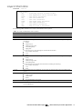
Contents
Command line interface
Introduction ..................................................................................................................................................................8
Additional references .................................................................................................................................................8
Connecting to the switch ..........................................................................................................................................8
Establishing a console connection .....................................................................................................................8
Setting an IP address .............................................................................................................................................9
Establishing a Telnet connection ........................................................................................................................9
Establishing an SSH connection ..........................................................................................................................9
Accessing the switch ................................................................................................................................................10
Idle timeout .................................................................................................................................................................11
Typographical conventions .....................................................................................................................................11
Menu basics
Introduction ................................................................................................................................................................13
Main Menu ..................................................................................................................................................................13
Menu summary ..........................................................................................................................................................13
Global commands ....................................................................................................................................................14
Command line history and editing ........................................................................................................................15
Command line interface shortcuts ........................................................................................................................16
Command stacking ............................................................................................................................................16
Command abbreviation ....................................................................................................................................16
Tab completion ....................................................................................................................................................16
First-time configuration
Introduction ................................................................................................................................................................17
Configuring Simple Network Management Protocol support.....................................................................17
Setting passwords ......................................................................................................................................................18
Changing the default administrator password ..............................................................................................18
Changing the default user password ..............................................................................................................19
Changing the default operator password......................................................................................................20
Information Menu
Introduction ................................................................................................................................................................21
Menu overview ..........................................................................................................................................................21
System Information Menu ........................................................................................................................................22
SNMPv3 Information Menu ......................................................................................................................................22
SNMPv3 USM User Table information ................................................................................................................23
SNMPv3 View Table information .......................................................................................................................24
SNMPv3 Access Table information ...................................................................................................................24
SNMPv3 Group Table information .....................................................................................................................25
SNMPv3 Community Table information ...........................................................................................................25
SNMPv3 Target Address Table information .....................................................................................................25
SNMPv3 Target Parameters Table information ...............................................................................................26
SNMPv3 Notify Table information ......................................................................................................................26
SNMPv3 dump ......................................................................................................................................................27
System information ....................................................................................................................................................28
Show last 100 syslog messages................................................................................................................................28
System user information ............................................................................................................................................29
Layer 2 information....................................................................................................................................................30
FDB information menu ..............................................................................................................................................31
Show all FDB information ....................................................................................................................................31
Clearing entries from the FDB ............................................................................................................................31
Link Aggregation Control Protocol information ...................................................................................................32
LACP dump ...........................................................................................................................................................32
802.1x information .....................................................................................................................................................33
Spanning Tree information .......................................................................................................................................34
Rapid Spanning Tree and Multiple Spanning Tree information ........................................................................36
Common Internal Spanning Tree information ......................................................................................................38
Trunk group information ...........................................................................................................................................39
VLAN information .......................................................................................................................................................40
Layer 2 general information ....................................................................................................................................40
Layer 3 information....................................................................................................................................................40
Route information ......................................................................................................................................................41
Show all Route information ................................................................................................................................42
ARP information .........................................................................................................................................................43
Show all ARP entry information .........................................................................................................................43
ARP address list information ...............................................................................................................................43
OSPF information .......................................................................................................................................................44
OSPF general information ..................................................................................................................................45
OSPF interface information ................................................................................................................................45
OSPF Database information ..............................................................................................................................45
OSPF route codes information...........................................................................................................................47
Routing Information Protocol information.............................................................................................................47
RIP Routes information ........................................................................................................................................47
RIP user configuration .........................................................................................................................................47
IP information..............................................................................................................................................................48
IGMP multicast group information .........................................................................................................................48
IGMP multicast router port information .................................................................................................................49
VRRP information .......................................................................................................................................................49
QoS information .........................................................................................................................................................50
802.1p information .....................................................................................................................................................50
ACL information .........................................................................................................................................................51
RMON Information Menu .........................................................................................................................................51
RMON history information ...................................................................................................................................51
RMON alarm information ...................................................................................................................................52
RMON event information ...................................................................................................................................54
Link status information ...............................................................................................................................................54
Port information..........................................................................................................................................................55
SFP information ...........................................................................................................................................................56
1-1
Uplink Failure Detection information ..........................................................................................................56
Information dump......................................................................................................................................................56
Statistics Menu
Introduction ................................................................................................................................................................57
Menu information ......................................................................................................................................................57
Port Statistics Menu....................................................................................................................................................57
802.1x statistics ......................................................................................................................................................58
Bridging statistics ..................................................................................................................................................60
Ethernet statistics ..................................................................................................................................................60
Interface statistics ................................................................................................................................................62
Internet Protocol (IP) statistics ............................................................................................................................63
Link statistics ..........................................................................................................................................................64
Port RMON statistics .............................................................................................................................................64
Layer 2 statistics ..........................................................................................................................................................66
FDB statistics ..........................................................................................................................................................66
LACP statistics .......................................................................................................................................................66
Layer 3 statistics ..........................................................................................................................................................67
GEA Layer 3 statistics menu ...............................................................................................................................68
GEA Layer 3 statistics ...........................................................................................................................................68
IP statistics ..............................................................................................................................................................68
Route statistics ......................................................................................................................................................69
ARP statistics ..........................................................................................................................................................69
DNS statistics .........................................................................................................................................................69
ICMP statistics .......................................................................................................................................................70
TCP statistics ..........................................................................................................................................................71
UDP statistics .........................................................................................................................................................72
IGMP Multicast Group statistics .........................................................................................................................72
OSPF statistics menu ............................................................................................................................................73
OSPF global statistics ...........................................................................................................................................73
VRRP statistics .......................................................................................................................................................76
Error! Use the Home tab to apply 見出し 1 to the text that you want to appear here.
RIP statistics............................................................................................................................................................77
Management Processor statistics ...........................................................................................................................77
Packet statistics ....................................................................................................................................................78
TCP statistics ..........................................................................................................................................................78
UDP statistics .........................................................................................................................................................79
CPU statistics .........................................................................................................................................................79
Access Control List (ACL) statistics menu ..............................................................................................................79
ACL statistics .........................................................................................................................................................80
SNMP statistics ............................................................................................................................................................80
NTP statistics ................................................................................................................................................................82
Uplink Failure Detection (UFD) statistics .................................................................................................................83
Statistics dump ...........................................................................................................................................................83
Configuration Menu
Introduction ................................................................................................................................................................84
Menu information ......................................................................................................................................................84
Viewing, applying, reverting, and saving changes ............................................................................................84
Viewing pending changes ......................................................................................................................................85
Applying pending changes ....................................................................................................................................85
Reverting changes ....................................................................................................................................................85
Saving the configuration ..........................................................................................................................................85
Reminders ...................................................................................................................................................................86
System configuration ................................................................................................................................................86
System host log configuration ...........................................................................................................................87
Secure Shell Server configuration .....................................................................................................................88
RADIUS server configuration ..............................................................................................................................89
TACACS+ server configuration ..........................................................................................................................90
NTP server configuration .....................................................................................................................................91
System SNMP configuration ...............................................................................................................................92
SNMPv3 configuration .........................................................................................................................................93
User Security Model configuration ....................................................................................................................94
SNMPv3 View configuration ...............................................................................................................................95
View-based Access Control Model configuration ........................................................................................96
SNMPv3 Group configuration ............................................................................................................................97
SNMPv3 Community Table configuration .......................................................................................................97
SNMPv3 Target Address Table configuration..................................................................................................98
SNMPv3 Target Parameters Table configuration ...........................................................................................98
SNMPv3 Notify Table configuration ..................................................................................................................99
System Access configuration ............................................................................................................................99
Management Networks configuration ......................................................................................................... 100
User Access Control configuration ................................................................................................................ 101
User ID configuration ........................................................................................................................................ 101
HTTPS Access configuration ............................................................................................................................ 102
Port configuration ................................................................................................................................................... 103
Temporarily disabling a port ........................................................................................................................... 104
Port link configuration ...................................................................................................................................... 104
Port ACL/QoS configuration ........................................................................................................................... 105
Layer 2 configuration ............................................................................................................................................. 105
802.1x configuration ............................................................................................................................................... 106
802.1x Global configuration............................................................................................................................ 106
802.1x Port configuration ................................................................................................................................. 107
Rapid Spanning Tree Protocol / Multiple Spanning Tree Protocol configuration ....................................... 109
Common Internal Spanning Tree configuration ......................................................................................... 110
CIST bridge configuration ................................................................................................................................ 110
CIST port configuration .................................................................................................................................... 112
Spanning Tree configuration ................................................................................................................................ 113
Bridge Spanning Tree configuration .............................................................................................................. 113
Spanning Tree port configuration .................................................................................................................. 114
Forwarding Database configuration .................................................................................................................. 115
Static FDB configuration .................................................................................................................................. 115
Trunk configuration ................................................................................................................................................. 116
IP Trunk Hash configuration ................................................................................................................................... 116
Layer 2 IP Trunk Hash configuration ............................................................................................................... 117
Link Aggregation Control Protocol configuration ............................................................................................ 117
LACP Port configuration .................................................................................................................................. 118
VLAN configuration ................................................................................................................................................ 118
Layer 3 configuration ............................................................................................................................................. 119
IP interface configuration ............................................................................................................................... 120
Default Gateway configuration .................................................................................................................... 120
IP Static Route configuration ................................................................................................................................ 121
Address Resolution Protocol configuration........................................................................................................ 121
Static ARP configuration .................................................................................................................................. 122
IP Forwarding configuration ................................................................................................................................. 122
Network Filter configuration.................................................................................................................................. 123
Route Map configuration ..................................................................................................................................... 123
IP Access List configuration .................................................................................................................................. 124
Routing Information Protocol configuration ...................................................................................................... 124
RIP Interface configuration ............................................................................................................................. 125
RIP Route Redistribution configuration .......................................................................................................... 126
Open Shortest Path First configuration ............................................................................................................... 127
OSPF Area Index configuration ...................................................................................................................... 128
OSPF Summary Range configuration ............................................................................................................ 129
OSPF Interface configuration ......................................................................................................................... 129
OSPF Virtual Link configuration ....................................................................................................................... 130
OSPF Host Entry configuration ........................................................................................................................ 130
OSPF Route Redistribution configuration ...................................................................................................... 131
OSPF MD5 Key configuration .......................................................................................................................... 131
IGMP configuration ................................................................................................................................................ 132
IGMP snooping configuration ........................................................................................................................ 132
IGMPv3 Snooping configuration .................................................................................................................... 133
IGMP static multicast router configuration .................................................................................................. 134
IGMP filtering configuration ............................................................................................................................ 134
IGMP filter definition ......................................................................................................................................... 134
IGMP filtering port configuration .................................................................................................................... 135
Domain Name System configuration ................................................................................................................. 136
Bootstrap Protocol Relay configuration ............................................................................................................. 136
Virtual Router Redundancy Protocol configuration ........................................................................................ 137
VRRP Virtual Router configuration ................................................................................................................. 137
VRRP Virtual Router Priority Tracking configuration .................................................................................... 139
VRRP Virtual Router Group configuration..................................................................................................... 140
VRRP Virtual Router Group Priority Tracking configuration ....................................................................... 141
VRRP Interface configuration ......................................................................................................................... 141
VRRP Tracking configuration .......................................................................................................................... 142
Quality of Service configuration .......................................................................................................................... 143
QoS 802.1p configuration................................................................................................................................ 143
Access Control configuration .............................................................................................................................. 143
Access Control List configuration ........................................................................................................................ 145
ACL Ethernet Filter configuration ................................................................................................................... 145
ACL IP Version 4 Filter configuration .............................................................................................................. 146
ACL TCP/UDP Filter configuration .................................................................................................................. 146
ACL Meter configuration ................................................................................................................................. 147
ACL Re-mark configuration ............................................................................................................................ 148
ACL Re-mark In-Profile configuration ............................................................................................................ 148
ACL Re-mark In-Profile Update User Priority configuration ........................................................................ 148
ACL Re-mark Out-of-Profile configuration ................................................................................................... 149
ACL Packet Format configuration ................................................................................................................. 149
ACL Group configuration ................................................................................................................................ 149
Remote Monitoring configuration ....................................................................................................................... 150
RMON history configuration ............................................................................................................................ 150
RMON event configuration ............................................................................................................................. 151
RMON alarm configuration ............................................................................................................................. 151
Port mirroring............................................................................................................................................................ 153
Port-based port mirroring ................................................................................................................................ 153
Error! Use the Home tab to apply 見出し 1 to the text that you want to appear here.
Uplink Failure Detection configuration ............................................................................................................... 154
Failure Detection Pair (FDP) configuration ................................................................................................... 154
Link to Monitor (LtM) configuration ............................................................................................................... 155
Link to Disable configuration .......................................................................................................................... 155
Configuration Dump .............................................................................................................................................. 156
Saving the active switch configuration .............................................................................................................. 156
Restoring the active switch configuration ......................................................................................................... 156
Operations Menu
Introduction ............................................................................................................................................................. 158
Menu information ................................................................................................................................................... 158
Operations-level port options ......................................................................................................................... 158
Operations-level port 802.1x options ............................................................................................................. 159
Operations-level VRRP options ....................................................................................................................... 159
Boot Options Menu
Introduction ............................................................................................................................................................. 160
Menu information ................................................................................................................................................... 160
Updating the switch software image ................................................................................................................. 160
Downloading new software to the switch ................................................................................................... 160
Selecting a software image to run ...................................................................................................................... 161
Uploading a software image from the switch .................................................................................................. 162
Selecting a configuration block .......................................................................................................................... 162
Resetting the switch ............................................................................................................................................... 164
Accessing the ISCLI ................................................................................................................................................ 164
Maintenance Menu
Introduction ............................................................................................................................................................. 165
Menu information ................................................................................................................................................... 165
System maintenance options ......................................................................................................................... 166
Forwarding Database options........................................................................................................................ 166
Debugging options........................................................................................................................................... 167
ARP cache options ........................................................................................................................................... 167
IP Route Manipulation options ....................................................................................................................... 168
IGMP Multicast Group options ....................................................................................................................... 168
IGMP Snooping options ................................................................................................................................... 168
IGMP Mrulticast Routers options ..................................................................................................................... 169
Technical support dump ....................................................................................................................................... 169
FTP/TFTP technical support dump put ........................................................................................................... 169
Uuencode flash dump ..................................................................................................................................... 169
FTP/TFTP system dump put ............................................................................................................................... 170
Clearing dump information ............................................................................................................................ 170
Panic command ............................................................................................................................................... 170
Unscheduled system dumps................................................................................................................................. 171
Command line interface
Introduction
The 10Gb Intelligent L3 Switch is ready to perform basic switching functions right out of the box. Some of
the more advanced features, however, require some administrative configuration before they can be
used effectively.
The extensive switching software included in the switch provides a variety of options for accessing and
configuring the switch:
Built-in, text-based command line interfaces (AOS CLI and ISCLI) for access via a local terminal or
remote Telnet/Secure Shell (SSH) session
Simple Network Management Protocol (SNMP) support for access through network management
software such as NEC WebSAM NetvisorPro
A browser-based management interface for interactive network access through the Web browser
The command line interface is the most direct method for collecting switch information and performing
switch configuration. Using a basic terminal, you can view information and statistics about the switch,
and perform any necessary configuration.
This chapter explains how to access the AOS CLI to the switch.
Additional references
Additional information about installing and configuring the switch is available in the following guides,
which are attached in this product.
N8406-026 10Gb Intelligent L3 Switch User’s Guide
N8406-026 10Gb Intelligent L3 Switch Application Guide
N8406-026 10Gb Intelligent L3 Switch Command Reference Guide (ISCLI)
N8406-026 10Gb Intelligent L3 Switch Browser-based Interface Reference Guide
Connecting to the switch
You can access the command line interface in one of the following ways:
Using a console connection via the console port
Using a Telnet connection over the network
Using a Secure Shell (SSH) connection to securely log in over a network
Establishing a console connection
To establish a console connection with the switch, you need:
A null modem cable with a female DB-9 connector (See the N8406-026 10Gb Intelligent L3 Switch
User’s Guide for more information.)
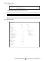
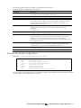
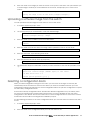
An ASCII terminal or a computer running terminal emulation software set to the parameters shown in
the table below
Table 1 Console configuration parameters
Parameter
Value
Baud Rate
Data Bits
Parity
Stop Bits
Flow Control
9600
8
None
1
None
Error! Use the Home tab to apply 見出し 1 to the text that you want to appear here.
8
To establish a console connection with the switch:
1.
Connect the terminal to the console port using the null modem cable.
2.
Power on the terminal.
3.
Press the Enter key a few times on the terminal to establish the connection.
4.
You will be required to enter a password for access to the switch. (For more information, see the
―Setting passwords‖ section in the ―First-time configuration‖ chapter.)
Setting an IP address
To access the switch via a Telnet or an SSH connection, you need to have an Internet Protocol (IP)
address set for the switch. The switch can get its IP address in one of the following ways:
Management port access:
Using a Dynamic Host Control Protocol (DHCP) server—When the /cfg/sys/dhcp command is
enabled, the management interface (interface 250) requests its IP address from a DHCP server.
The default value for the /cfg/sys/dhcp command is enabled.
Configuring manually—If the network does not support DHCP, you must configure the
management interface (interface 256) with an IP address. If you want to access the switch from
a remote network, you also must configure the management gateway (gateway 254).
Uplink port access:
Using a Bootstrap Protocol (BOOTP) server—By default, the management interface is set up to
request its IP address from a BOOTP server. If you have a BOOTP server on the network, add the
Media Access Control (MAC) address of the switch to the BOOTP configuration file located on
the BOOTP server. The MAC address can be found in the System Information menu (See the
―System information‖ section in the ―Information Menu‖ chapter.) If you are using a DHCP server
that also does BOOTP, you do not have to configure the MAC address.
Configuring manually—If the network does not support BOOTP, you must configure the
management port with an IP address.
Establishing a Telnet connection
A Telnet connection offers the convenience of accessing the switch from any workstation connected to
the network. Telnet provides the same options for user, operator, and administrator access as those
available through the console port. By default, Telnet is enabled on the switch. The switch supports four
concurrent Telnet connections.
Once the IP parameters are configured, you can access the CLI using a Telnet connection. To establish a
Telnet connection with the switch, run the Telnet program on the workstation and enter the telnet
command, followed by the switch IP address:
telnet <10Gb Intelligent L3 Switch IP address>
You will then be prompted to enter a password. The password entered determines the access level:
administrator, operator, or user. See the ―Accessing the switch‖ section later in this chapter for description
of default passwords.
Establishing an SSH connection
Although a remote network administrator can manage the configuration of a switch via Telnet, this
method does not provide a secure connection. The Secure Shell (SSH) protocol enables you to securely
log into the switch over the network.
As a secure alternative to using Telnet to manage switch configuration, SSH ensures that all data sent
over the network is encrypted and secure. In order to use SSH, you must first configure it on the switch.
See the ―Secure Shell Server configuration‖ section in the ―Configuration Menu‖ chapter for information
on how to configure SSH.
The switch can perform only one session of key/cipher generation at a time. Therefore, an SSH/Secure
Copy (SCP) client will not be able to log in if the switch is performing key generation at that time or if
another client has just logged in before this client. Similarly, the system will fail to perform the key
generation if an SSH/SCP client is logging in at that time.
Error! Use the Home tab to apply 見出し 1 to the text that you want to appear here.
9
The supported SSH encryption and authentication methods are listed below.
Server Host Authentication—Client RSA authenticates the switch in the beginning of every
connection
Key Exchange—RSA
Encryption:
AES256-CBC
AES192-CBC
AES128-CBC
3DES-CBC
3DES
ARCFOUR
User Authentication—Local password authentication; Remote Authentication Dial-in User Service
(RADIUS)
The following SSH clients are supported:
SSH 3.0.1 for Linux (freeware)
SecureCRT® 4.1.8 (VanDyke Technologies, Inc.)
OpenSSH_3.9 for Linux (FC 3)
SCP commands for Linux (FC3)
PuTTY Release 0.58 (Simon Tatham) for Windows
NOTE: The switch implementation of SSH is based on versions 1.5 and 2.0, and supports SSH clients
from version 1.0 through version 2.0. SSH clients of other versions are not supported. You may
configure the client software to use protocol SSH version 1 or version 2.
By default, SSH service is not enabled on the switch. Once the IP parameters are configured, you can
access the command line interface to enable SSH.
To establish an SSH connection with the switch, run the SSH program on the workstation by issuing the ssh
command, followed by the user account name and the switch IP address:
>> # ssh <user>@<10Gb Intelligent L3 Switch IP address>
You will then be prompted to enter your password.
NOTE: The first time you run SSH from the workstation, a warning message might appear. At the
prompt, enter yes to continue.
Accessing the switch
To enable better switch management and user accountability, the switch provides different levels or
classes of user access. Levels of access to the CLI and Web management functions and screens increase
as needed to perform various switch management tasks. The three levels of access are:
User—User interaction with the switch is completely passive; nothing can be changed on the switch.
Users may display information that has no security or privacy implications, such as switch statistics
and current operational state information.
Operator—Operators can only effect temporary changes on the switch. These changes will be lost
when the switch is rebooted/reset. Operators have access to the switch management features used
for daily switch operations. Because any changes an operator makes are undone by a reset of the
switch, operators cannot severely impact switch operation, but do have access to the Maintenance
menu.
Administrator—Only administrators can make permanent changes to the switch configuration,
changes that are persistent across a reboot/reset of the switch. Administrators can access switch
functions to configure and troubleshoot problems on the switch. Because administrators can also
make temporary (operator-level) changes as well, they must be aware of the interactions between
temporary and permanent changes.
Access to switch functions is controlled through the use of unique usernames and passwords. Once you
are connected to the switch via the local console, Telnet, or SSH, you are prompted to enter a password.
The password entered determines the access level. The default user names/password for each access
level is listed in the following table.
Error! Use the Home tab to apply 見出し 1 to the text that you want to appear here.
10
NOTE: It is recommended that you change default switch passwords after initial configuration and
as regularly as required under your network security policies. For more information, see the ―Setting
passwords‖ section in the ―First-time configuration‖ chapter.
Table 2 User access levels
User account
Description and tasks performed
User
The user has no direct responsibility for switch management. He or she can
view all switch status information and statistics, but cannot make any
configuration changes to the switch. The user account is enabled by default,
and the default password is user.
The operator manages all functions of the switch. The operator can reset ports
or the entire switch. By default, the operator account is disabled and has no
password.
The super user administrator has complete access to all menus, information,
and configuration commands on the switch, including the ability to change
both the user and administrator passwords. The admin account is enabled by
default, and the default password is admin.
Oper
Admin
NOTE: With the exception of the admin user, setting the password to an empty value can disable
access to each user level.
Once you enter the administrator password and it is verified, you are given complete access to the
switch.
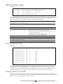
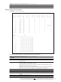
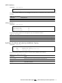
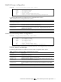
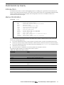
After logging in, the Main Menu of the CLI is displayed. See the ―Menu basics‖ chapter for a summary of
the Main Menu options.
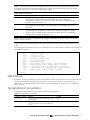
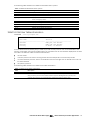
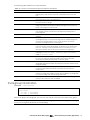
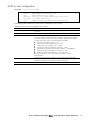
[Main Menu]
info
stats
cfg
oper
boot
maint
diff
apply
save
revert
exit
-
Information Menu
Statistics Menu
Configuration Menu
Operations Command Menu
Boot Options Menu
Maintenance Menu
Show pending config changes [global command]
Apply pending config changes [global command]
Save updated config to FLASH [global command]
Revert pending or applied changes [global command]
Exit [global command, always available]
>> Main#
Idle timeout
By default, the switch will disconnect the console, Telnet, or SSH session after five minutes of inactivity. This
function is controlled by the idle timeout parameter, which can be set from 1 to 60 minutes. For
information on changing this parameter, see the ―System configuration‖ section in the ―Configuration
Menu‖ chapter.
Typographical conventions
The following table describes the typographic styles used in this guide:
Table 3 Typographic conventions
Typeface or symbol
Meaning
Example
AaBbCc123
This type depicts onscreen computer output
and prompts.
This type displays in command examples and
shows text that must be typed in exactly as
shown.
Main#
AaBbCc123
Main# sys
Error! Use the Home tab to apply 見出し 1 to the text that you want to appear here.
11
Table 3 Typographic conventions
Typeface or symbol
Meaning
Example
<AaBbCc123>
This italicized type displays in command
examples as a parameter placeholder.
Replace the indicated text with the
appropriate real name or value when using
the command. Do not type the brackets.
This also shows guide titles, special terms, or
words to be emphasized.
Command items shown inside brackets are
optional and can be used or excluded as the
situation demands. Do not type the brackets.
To establish a Telnet session, enter:
[ ]
host# telnet <IP address>
Read the user guide thoroughly.
host# ls [-a]
Error! Use the Home tab to apply 見出し 1 to the text that you want to appear here.
12
Menu basics
Introduction
The AOS CLI is used for viewing switch information and statistics. In addition, the administrator can use the
CLI for performing all levels of switch configuration.
To make the CLI easy to use, the various commands have been logically grouped into a series of menus
and submenus. Each menu displays a list of commands and/or submenus that are available, along with a
summary of what each command will do. Below each menu is a prompt where you can enter any
command appropriate to the current menu.
This chapter describes the Main Menu commands, and provides a list of commands and shortcuts that
are commonly available from all the menus within the CLI.
Main Menu
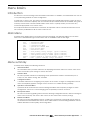
The Main Menu displays after a successful connection and login. The following table shows the Main
Menu for the administrator login. Some features are not available under the user login.
[Main Menu]
info
stats
cfg
oper
boot
maint
diff
apply
save
revert
exit
-
Information Menu
Statistics Menu
Configuration Menu
Operations Command Menu
Boot Options Menu
Maintenance Menu
Show pending config changes [global command]
Apply pending config changes [global command]
Save updated config to FLASH [global command]
Revert pending or applied changes [global command]
Exit [global command, always available]
Menu summary
The Main Menu displays the following submenus:
Information Menu
The Information Menu provides submenus for displaying information about the current status of the
switch: from basic system settings to VLANs, and more.
Statistics Menu
This menu provides submenus for displaying switch performance statistics. Included are port, IP,
ICMP, TCP, UDP, SNMP, routing, ARP, and DNS.
Configuration Menu
It includes submenus for configuring every aspect of the switch. Changes to configuration are not
active until explicitly applied. Changes can be saved to non-volatile memory (NVRAM).
Operations Command Menu
Operations-level commands are used for making immediate and temporary changes to switch
configuration. This menu is used for bringing ports temporarily in and out of service.
Boot Options Menu
This menu is used for upgrading switch software, selecting configuration blocks, and for resetting the
switch when necessary. This menu is also used to set the switch back to factory settings.
Maintenance Menu
This menu is used for debugging purposes, enabling you to generate a technical support dump of
the critical state information in the switch, and to clear entries in the Forwarding Database and the
Address Resolution Protocol (ARP) and routing tables.
Error! Use the Home tab to apply 見出し 1 to the text that you want to appear here.
13
Global commands
Some basic commands are recognized throughout the menu hierarchy. These commands are useful for
obtaining online Help, navigating through menus, and for applying and saving configuration changes.
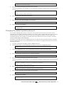
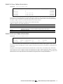
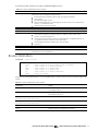
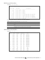
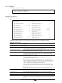
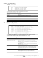
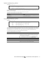
For help on a specific command, type help. The following screen displays:
>> Main# help
For help on a specific command, type help <command>
Global Commands: [can be issued from any menu]
help
up
print
lines
verbose
exit
diff
apply
save
ping
traceroute
telnet
pushd
popd
who
pwd
quit
revert
history
The following are used to navigate the menu structure:
. Print current menu
.. Move up one menu level
/ Top menu if first, or command separator
! Execute command from history
The following table describes the global commands.
Table 4 Global commands
Command
Action
? or help
Provides usage information about a specific command on the current menu.
When used without the command parameter, a summary of the global
commands is displayed.
Displays the current menu.
Moves up one level in the menu structure.
If placed at the beginning of a command, displays the Main Menu. Otherwise,
this is used to separate multiple commands placed on the same line.
Sets the number of lines (n) that display on the screen at one time. The default is
24 lines. When used without a value, the current setting is displayed.
Shows any pending configuration changes that have not been applied.
diff flash displays all pending configuration changes that have been
applied but not saved to flash memory (NVRAM), as well as those that have not
been applied.
Applies pending configuration changes.
Saves the active configuration to backup, and saves the current configuration
as active.
Save n saves the current configuration as active, without saving the active
configuration to backup.
Removes changes that have been made, but not applied.
Revert apply removes all changes that have not been saved.
Exits from the command line interface and logs out.
Verifies station-to-station connectivity across the network. The format is:
. or print
.. or up
/
lines
diff
apply
save
revert
exit or quit
ping
ping <host name> | <IP address> [ <number of tries> [
<msec delay> ]] [-m|-mgt|-d|-data]
traceroute
IP address is the hostname or IP address of the device.
number of tries (optional) is the number of attempts (1-32).
msec delay (optional) is the number of milliseconds between attempts.
Identifies the route used for station-to-station connectivity across the network.
The format is:
traceroute <host name> | <IP address> [<max-hops> [ <msec
delay> ]]
pwd
IP address is the hostname or IP address of the target station.
max-hops (optional) is the maximum distance to trace (1-16 devices)
msec delay (optional) is the number of milliseconds to wait for the
response.
Displays the command path used to reach the current menu.
Error! Use the Home tab to apply 見出し 1 to the text that you want to appear here.
14
Table 4 Global commands
Command
Action
verbose n
Sets the level of information displayed on the screen:
0 = Quiet: Nothing displays except errors, not even prompts.
1 = Normal: Prompts and requested output are shown, but no menus.
2 = Verbose: Everything is shown. This is the default.
When used without a value, the current setting is displayed.
This command is used to Telnet out of the switch. The format is:
telnet
telnet <hostname> | <IP address> [port]
history
pushd
popd
who
Displays the history of the last ten commands.
Remembers the current location in the directory of menu commands.
Returns to the last pushd location.
Displays users who are logged in.
Command line history and editing
Using the command line interface, you can retrieve and modify previously entered commands with just a
few keystrokes. The following options are available globally at the command line:
Table 5 Command line history and editing options
Option
Description
history
!!
!n
<Ctrl-p> or
Displays a numbered list of the last ten previously entered commands.
Repeats the last entered command.
Repeats the nth command shown on the history list.
Recalls the previous command from the history list. This can be used multiple times
to work backward through the last ten commands. The recalled command can be
entered as is, or edited using the options below.
Recalls the next command from the history list. This can be used multiple times to
work forward through the last ten commands. The recalled command can be
entered as is, or edited using the options below.
Moves the cursor to the beginning of the command line.
Moves the cursor to the end of the command line.
Moves the cursor back one position to the left.
Up arrow key
<Ctrl-n> or
Down arrow key
<Ctrl-a>
<Ctrl-e>
<Ctrl-b> or
Left arrow key
<Ctrl-f> or
Right arrow key
Moves the cursor forward one position to the right.
<Backspace> or
Erases one character to the left of the cursor position.
Delete key
<Ctrl-d>
<Ctrl-k>
<Ctrl-l>
<Ctrl-u>
Other keys
.
..
Deletes one character at the cursor position.
Erases all characters from the cursor position to the end of the command line.
Redisplays the current line.
Clears the entire line.
Inserts new characters at the cursor position.
Prints the current level menu list.
Moves to the previous directory level.
Error! Use the Home tab to apply 見出し 1 to the text that you want to appear here.
15
Command line interface shortcuts
The following shortcuts allow you to enter commands quickly and easily.
Command stacking
As a shortcut, you can type multiple commands on a single line, separated by forward slashes (/). You
can connect as many commands as required to access the menu option that you want.
For example, the keyboard shortcut to access the Simple Network Management Protocol (SNMP)
Configuration Menu from the Main# prompt is:
Main# cfg/sys/ssnmp/name
Command abbreviation
Most commands can be abbreviated by entering the first characters that distinguish the command from
the others in the same menu or submenu.
For example, the command shown above could also be entered as:
Main# c/sys/ssn/n
Tab completion
By entering the first letter of a command at any menu prompt and pressing the Tab key, the CLI will
display all commands or options in that menu that begin with that letter. Entering additional letters will
further refine the list of commands or options displayed.
If only one command fits the input text when the Tab key is pressed, that command will be supplied on
the command line, waiting to be entered. If the Tab key is pressed without any input on the command
line, the currently active menu displays.
Error! Use the Home tab to apply 見出し 1 to the text that you want to appear here.
16
First-time configuration
Introduction
This chapter describes how to perform first-time configuration and how to change system passwords.
To begin first-time configuration of the switch, perform the following steps.
1.
Connect to the switch console. After connecting, the login prompt displays.
Blade Network Technologies 10Gb Intelligent L3 Switch.
Enter password:
2.
Enter admin as the default administrator password.
The system displays the Main Menu with administrator privileges.
[Main Menu]
info
stats
cfg
oper
boot
maint
diff
apply
save
revert exit
-
Information Menu
Statistics Menu
Configuration Menu
Operations Command Menu
Boot Options Menu
Maintenance Menu
Show pending config changes [global command]
Apply pending config changes [global command]
Save updated config to FLASH [global command]
Revert pending or applied changes [global command]
Exit [global command, always available]
>> Main#
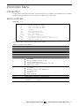
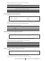
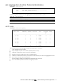
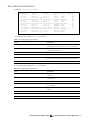
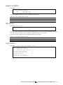
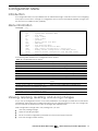
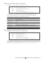
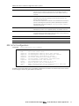
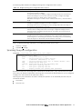
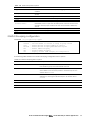
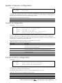
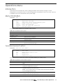
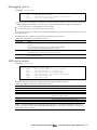
3.
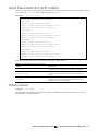
From the Main Menu, enter the following command to access the Configuration Menu:
Main# /cfg
The Configuration Menu is displayed.
[Configuration Menu]
sys
- System-wide Parameter Menu
port
- Port Menu
l2
- Layer 2 Menu
l3
- Layer 3 Menu
qos
- QOS Menu
acl
- Access Control List Menu
rmon
- RMON Menu
pmirr
- Port Mirroring Menu
ufd
- Uplink Failure Detection Menu
dump
- Dump current configuration to script file
ptcfg
- Backup current configuration to FTP/TFTP server
gtcfg
- Restore current configuration from FTP/TFTP server
cur
- Display current configuration
>> Configuration#
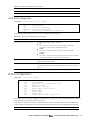
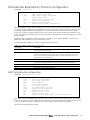
Configuring Simple Network Management Protocol support
NOTE:
1.
SNMP support is enabled by default.
Use the following command to enable SNMP:
>> # /cfg/sys/access/snmp disable|read only|read/write
2.
Set SNMP read or write community string. By default, they are public and private respectively:
>> # /cfg/sys/ssnmp/rcomm|wcomm
3.
When prompted, enter the proper community string.
Error! Use the Home tab to apply 見出し 1 to the text that you want to appear here.
17
4.
Apply and save configuration .
>> System# apply
>> System# save
Setting passwords
NEC recommends that you change all passwords after initial configuration and as regularly as required
under the network security policies. See the ―Accessing the switch‖ section in the ―Command line
interface‖ chapter for a description of the user access levels.
To change the user, operator, or administrator password, you must log in using the administrator
password. Passwords cannot be modified from the user or operator command mode.
NOTE: You must not forget your administrator password. If you forget your administrator password,
contact your service representative.
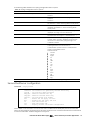
Changing the default administrator password
The administrator has complete access to all menus, information, and configuration commands,
including the ability to change the user, operator, and administrator passwords.
The default password for the administrator account is admin. To change the default password:
1.
Connect to the switch and log in using the admin password.
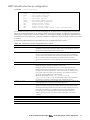
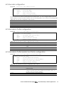
2.
From the Main Menu, use the following command to access the Configuration Menu:
Main# /cfg
The Configuration Menu is displayed.
[Configuration Menu]
sys
- System-wide Parameter Menu
port
- Port Menu
l2
- Layer 2 Menu
l3
- Layer 3 Menu
qos
- QOS Menu
acl
- Access Control List Menu
rmon
- RMON Menu
pmirr
- Port Mirroring Menu
ufd
- Uplink Failure Detection Menu
dump
- Dump current configuration to script file
ptcfg
- Backup current configuration to FTP/TFTP server
gtcfg
- Restore current configuration from FTP/TFTP server
cur
- Display current system access configuration
>> Configuration#
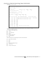
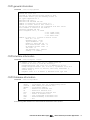
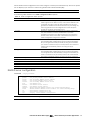
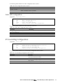
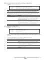
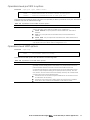
3.
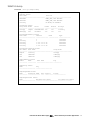
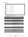
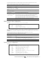
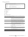
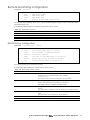
From the Configuration Menu, use the following command to select the System Menu:
>> Configuration# sys
The System Menu is displayed.
Error! Use the Home tab to apply 見出し 1 to the text that you want to appear here.
18
[System Menu]
syslog
sshd
radius
tacacs+
ntp
ssnmp
access
date
time
timezone
olddst
dlight
idle
notice
bannr
hprompt
bootp
dhcp
reminder
cur
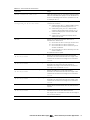
4.
-
Syslog Menu
SSH Server Menu
RADIUS Authentication Menu
TACACS+ Authentication Menu
NTP Server Menu
System SNMP Menu
System Access Menu
Set system date
Set system time
Set system timezone
Set system DST for US
Set system daylight savings
Set timeout for idle CLI sessions
Set login notice
Set login banner
Enable/disable display hostname (sysName) in CLI prompt
Enable/disable use of BOOTP
Enable/disable use of DHCP on Mgmt interface
Enable/disable Reminders
Display current system-wide parameters
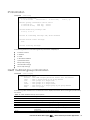
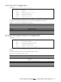
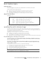
Enter the following command to set the administrator password:
System# access/user/admpw
5.
Enter the current administrator password at the prompt:
Changing ADMINISTRATOR password; validation required:
Enter current admin password:
NOTE: You must not forget your administrator password. If you forget your administrator password,
contact your service representative.
6.
Enter the new administrator password at the prompt:
Enter new administrator password (max 128 characters):
7.
Enter the new administrator password, again, at the prompt:
Re-enter new admin password:
8.
Apply and save the change by entering the following commands:
System# apply
System# save
Changing the default user password
The user login has limited control of the switch. Through a user account, you can view switch information
and statistics, but you cannot make configuration changes.
The default password for the user account is user. This password cannot be changed from the user
account. Only the administrator has the ability to change passwords, as shown in the following
procedure.
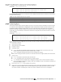
1.
Connect to the switch and log in using the admin password.
2.
From the Main Menu, use the following command to access the Configuration Menu:
Main# cfg
3.
From the Configuration Menu, use the following command to select the System Menu:
>> Configuration# sys
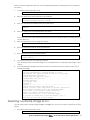
4.
Enter the following command to set the user password:
Error! Use the Home tab to apply 見出し 1 to the text that you want to appear here.
19
System# access/user/usrpw
5.
Enter the current administrator password at the prompt.
Only the administrator can change the user password. Entering the administrator password confirms
your authority.
Changing USER password; validation required:
Enter current admin password:
6.
Enter the new user password at the prompt:
Enter new user password (max 128 characters):
7.
Enter the new user password, again, at the prompt:
Re-enter new user password:
8.
Apply and save the changes:.
System# apply
System# save
Changing the default operator password
The operator manages all functions of the switch. The operator can reset ports or the entire switch.
Operators can only effect temporary changes on the switch. These changes will be lost when the switch
is rebooted/reset. Operators have access to the switch management features used for daily switch
operations. Because any changes an operator makes are undone by a reset of the switch, operators
cannot severely impact switch operation.
By default, the operator account is disabled and has no password. This password cannot be changed
from the operator account. Only the administrator has the ability to change passwords, as shown in the
following procedure.
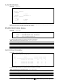
1.
Connect to the switch and log in using the admin password.
2.
From the Main Menu, use the following command to access the Configuration Menu:
Main# cfg
3.
From the Configuration Menu, use the following command to select the System Menu:
>> Configuration# sys
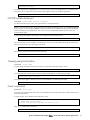
4.
Enter the following command to set the operator password:
System# access/user/opw
5.
Enter the current administrator password at the prompt.
Only the administrator can change the user password. Entering the administrator password confirms
your authority.
Changing OPERATOR password; validation required:
Enter current admin password:
6.
Enter the new operator password at the prompt:
Enter new operator password (max 128 characters):
7.
Enter the new operator password, again, at the prompt:
Re-enter new operator password:
8.
Apply and save the changes:
System# apply
System# save
Error! Use the Home tab to apply 見出し 1 to the text that you want to appear here.
20
Information Menu
Introduction
You can view configuration information for the switch in the user, operator, and administrator command
modes. This chapter discusses how to use the CLI to display switch information.
Menu overview
Command: /info
[Information Menu]
sys
- System Information Menu
l2
- Layer 2 Information Menu
l3
- Layer 3 Information Menu
qos
- QOS Menu
acl
- Show ACL information
rmon
- Show RMON information
link
- Show link status
port
- Show port information
sfp
- Show External Port SFP/XFP status
ufd
- Show Uplink Failure Detection information
dump
- Dump all information
The following table describes the Information Menu options.
Table 6 Information Menu options
Command
Usage
sys
l2
l3
qos
acl
rmon
link
Displays system information.
Displays the Layer 2 Information Menu.
Displays the Layer 3 Information Menu.
Displays the Quality of Service (QoS) Information Menu.
Displays the Access Control List (ACL) Information Menu.
Displays the Remote Monitoring Information Menu.
Displays configuration information about each port, including:
Port number
Port speed (10 Mb/s, 100 Mb/s, or auto)
Duplex mode (half, full, or any)
Flow control for transmit and receive (no, yes, or any)
Link status (up or down)
Displays port status information, including:
Port number
Whether the port uses VLAN tagging or not
Port VLAN ID (PVID)
Port name
VLAN membership
Displays SFP module information.
Displays (UFD) Uplink Failure Detection information
Dumps all switch information available from the Information Menu (10K or more,
depending on your configuration).
port
sfp
ufd
dump
Error! Use the Home tab to apply 見出し 1 to the text that you want to appear here.
21
System Information Menu
Command: /info/sys
[System Menu]
snmpv3
general
log
user
dump
-
SNMPv3 Information Menu
Show general system information
Show last 100 syslog messages
Show current user status
Dump all system information
The following table describes the System Information Menu options.
Table 7 System Information Menu options
Command
Usage
snmpv3
general
Displays the SNMP v3 Menu.
Displays system information, including:
System date and time
Switch model name and number
Switch name and location
Time of last boot
MAC address of the switch management processor
IP address of IP interface
Hardware version and part number
Software image file and version number
Configuration name
Log-in banner, if one is configured
Displays most recent syslog messages.
Displays the User Access Information Menu.
Dumps all switch information available from the Information Menu (10K or more,
depending on your configuration).
log
user
dump
SNMPv3 Information Menu
Command: /info/sys/snmpv3
[SNMPv3 Information Menu]
usm
- Show usmUser table information
view
- Show vacmViewTreeFamily table information
access
- Show vacmAccess table information
group
- Show vacmSecurityToGroup table information
comm
- Show community table information
taddr
- Show targetAddr table information
tparam
- Show targetParams table information
notify
- Show notify table information
dump
- Show all SNMPv3 information
SNMP version 3 (SNMPv3) is an extensible SNMP Framework that supplements the SNMPv2 Framework by
supporting the following:
a new SNMP message format
security for messages
access control
remote configuration of SNMP parameters
For more details on the SNMPv3 architecture, see RFC2271 to RFC2276.
Error! Use the Home tab to apply 見出し 1 to the text that you want to appear here.
22
The following table describes the SNMPv3 Information Menu options.
Table 8 SNMPv3 Information Menu options
Command
Usage
usm
view
access
group
Displays User Security Model (USM) table information.
Displays information about view name, subtrees, mask and type of view.
Displays View-based Access Control information.
Displays information about the group that includes the security model, user
name, and group name.
Displays information about the community table.
Displays the Target Address table.
Displays the Target parameters table.
Displays the Notify table.
Displays all the SNMPv3 information.
comm
taddr
tparam
notify
dump
SNMPv3 USM User Table information
Command: /info/sys/snmpv3/usm
usmUser Table:
User Name
-------------------------------adminmd5
adminsha
v1v2only
Protocol
-------------------------------HMAC_MD5, DES PRIVACY
HMAC_SHA, DES PRIVACY
NO AUTH, NO PRIVACY
The User-based Security Model (USM) in SNMPv3 provides security services such as authentication and
privacy of messages. This security model makes use of a defined set of user identities displayed in the USM
user table. The USM user table contains information like:
the user name
a security name in the form of a string whose format is independent of the Security Model
an authentication protocol, which is an indication that the messages sent on behalf of the user can
be authenticated
the privacy protocol.
The following table describes the SNMPv3 User Table information.
Table 9 SNMPv3 User Table parameters
Field
Description
User Name
Protocol
This is a string that represents the name of the user that you can use to access the switch.
This indicates whether messages sent on behalf of this user are protected from disclosure
using a privacy protocol. The switch software supports DES algorithm for privacy. The
software also supports two authentication algorithms: MD5 and HMAC-SHA.
Error! Use the Home tab to apply 見出し 1 to the text that you want to appear here.
23
SNMPv3 View Table information
Command: /info/sys/snmpv3/view
View Name
Subtree
------------------ ---------------------------iso
1
v1v2only
1
v1v2only
1.3.6.1.6.3.15
v1v2only
1.3.6.1.6.3.16
v1v2only
1.3.6.1.6.3.18
Mask
-------------
Type
-------included
included
excluded
excluded
excluded
The user can control and restrict the access allowed to a group to only a subset of the management
information in the management domain that the group can access within each context by specifying
the group‘s rights in terms of a particular MIB view for security reasons.
The following table describes the SNMPv3 View Table information.
Table 10 SNMPv3 View Table parameters
Field
Description
View Name
Subtree
Displays the name of the view.
Displays the MIB subtree as an OID string. A view subtree is the set of all MIB object
instances which have a common Object Identifier prefix to their names.
Displays the bit mask.
Displays whether a family of view subtrees is included or excluded from the MIB view.
Mask
Type
SNMPv3 Access Table information
Command: /info/sys/snmpv3/access
Group Name
---------v1v2grp
admingrp
Model
------snmpv1
usm
Level
-----------noAuthNoPriv
authPriv
ReadV
WriteV
--------- -------iso
iso
iso
iso
NotifyV
------v1v2only
iso
The vacmAccessTable (View-based Access Control Model Access Table) maps a group name, security
information, and a message type, which could be the read or write type of operation or notification into
a MIB view.
This group‘s access rights are determined by a Read View, a Write View, and a Notify View. The Read
View represents the set of object instances authorized for the group while reading the objects. The Write
View represents the set of object instances authorized for the group when writing objects. The Notify View
represents the set of object instances authorized for the group when sending a notification.
Error! Use the Home tab to apply 見出し 1 to the text that you want to appear here.
24
The following table describes the SNMPv3 Access Table information.
Table 11 SNMPv3 Access Table parameters
Field
Description
Group Name
Model
Level
Displays the name of group.
Displays the security model used, for example, SNMPv1, or SNMPv2 or USM.
Displays the minimum level of security required to gain rights of access. For
example, noAuthNoPriv, authNoPriv, or auth-Priv.
Displays the MIB view to which this entry authorizes the Read access.
Displays the MIB view to which this entry authorizes the Write access.
Displays the MIB view to which this entry authorizes the Notify access.
ReadV
WriteV
NotifyV
SNMPv3 Group Table information
Command: /info/sys/snmpv3/group
Sec Model
---------snmpv1
usm
usm
User Name
----------------------------v1v2only
adminmd5
adminsha
Group Name
------------------------------v1v2grp
admingrp
admingrp
A group is a combination of security model and security name that defines the access rights assigned to
all the security names belonging to that group. The group is identified by a group name.
The following table describes the SNMPv3 Group Table information.
Table 12 SNMPv3 Group Table parameters
Field
Description
Sec Model
Displays the security model used, which is any one of: USM, SNMPv1, SNMPv2, and
SNMPv3.
Displays the name for the user.
Displays the access name of the group.
User Name
Group Name
SNMPv3 Community Table information
Command: /info/sys/snmpv3/comm
Index
Name
User Name
Tag
---------- ---------- -------------------- ---------trap1
public
v1v2only
v1v2trap
This command displays the community table information stored in the SNMP engine.
The following table describes the SNMPv3 Community Table information.
Table 13 SNMPv3 Community Table parameters
Field
Description
Index
Name
User Name
Tag
Displays the unique index value of a row in this table.
Displays the community string.
Displays the User Security Model (USM) user name.
Displays the community tag.
SNMPv3 Target Address Table information
Command: /info/sys/snmpv3/taddr
Name
Transport Addr Port Taglist
Params
---------- --------------- ---- ---------- --------------trap1
47.81.25.66
162 v1v2trap
v1v2param
This command displays the SNMPv3 target address table information.
The following table describes the SNMPv3 Target Address Table information.
Error! Use the Home tab to apply 見出し 1 to the text that you want to appear here.
25
Table 14 SNMPv3 Target Address Table parameters
Field
Description
Name
Displays the locally arbitrary, but unique identifier associated with this
snmp TargetAddrEntry.
Displays the transport addresses.
Displays the SNMP UDP port number.
This column contains a list of tag values which are used to select target addresses
for a particular SNMP message.
The value of this object identifies an entry in the snmpTargetParamsTable. The
identified entry contains SNMP parameters to be used when generating messages
to be sent to this transport address.
Transport Addr
Port
Taglist
Params
SNMPv3 Target Parameters Table information
Command: /info/sys/snmpv3/tparam
Name
MP Model User Name
Sec Model Sec Level
------------------- -------- -------------------- --------- ----------v1v2param
snmpv2c v1v2only
snmpv1
noAuthNoPriv
The following table describes the SNMPv3 Target Parameters Table information.
Table 15 SNMPv3 Target Parameters Table
Field
Description
Name
Displays the locally arbitrary, but unique identifier associated with this
snmpTargeParamsEntry.
Displays the Message Processing Model used when generating SNMP messages
using this entry.
Displays the securityName, which identifies the entry on whose behalf SNMP
messages will be generated using this entry.
Displays the security model used when generating SNMP messages using this entry.
Displays the level of security used when generating SNMP messages using this entry.
MP Model
User Name
Sec Model
Sec Level
SNMPv3 Notify Table information
Command: /info/sys/snmpv3/notify
Name
Tag
-------------------- -------------------v1v2trap
v1v2trap
The following table describes the SNMPv3 Notify Table information.
Table 16 SNMPv3 Notify Table
Field
Description
Name
Tag
The locally arbitrary, but unique identifier associated with this snmpNotifyEntry.
This represents a single tag value which is used to select entries in the
snmpTargetAddrTable. Any entry in the snmpTargetAddrTable that contains a
tag value equal to the value of this entry is selected. If this entry contains a value of
zero length, no entries are selected.
Error! Use the Home tab to apply 見出し 1 to the text that you want to appear here.
26
SNMPv3 dump
Command: /info/sys/snmpv3/dump
Engine ID = 80:00:07:50:03:00:17:EF:EB:B0:00
usmUser Table:
User Name
Protocol
-------------------------------- -------------------------------adminmd5
HMAC_MD5, DES PRIVACY
adminsha
HMAC_SHA, DES PRIVACY
v1v2only
NO AUTH, NO PRIVACY
vacmAccess
Group Name
---------v1v2grp
admingrp
Table:
Model
------snmpv1
usm
Level
-----------noAuthNoPriv
authPriv
ReadV
------iso
iso
WriteV
-------iso
iso
vacmViewTreeFamily Table:
View Name
Subtree
Mask
-------------------- --------------- -----------iso
1
v1v2only
1
v1v2only
1.3.6.1.6.3.15
v1v2only
1.3.6.1.6.3.16
v1v2only
1.3.6.1.6.3.18
vacmSecurityToGroup Table:
Sec Model User Name
---------- ------------------------------snmpv1
v1v2only
usm
adminmd5
usm
adminsha
NotifyV
-----v1v2only
iso
Type
-------------included
included
excluded
excluded
excluded
Group Name
----------------------v1v2grp
admingrp
admingrp
snmpCommunity Table:
Index
Name
User Name
Tag
---------- ---------- -------------------- ---------snmpNotify Table:
Name
Tag
-------------------- -------------------snmpTargetAddr Table:
Name
Transport Addr Port Taglist
Params
---------- --------------- ---- ---------- --------------snmpTargetParams Table:
Name
MP Model User Name
Sec Model Sec Level
-------------------- -------- ------------------ --------- -------
Error! Use the Home tab to apply 見出し 1 to the text that you want to appear here.
27
System information
Command: /info/sys/gen
System Information at 16:06:28 Tue Mar
Time zone: Asia/Tokyo
Daylight Savings Time Status: Disabled
4, 2008
Blade Network Technologies 10Gb Intelligent L3 Switch
sysName: Groly
sysLocation:
RackName: emfw-rack
EnclosureName: Default_Chassis_Name
BayNumber: 7
System temperature: 42.5C
Switch has been up for 7 days, 19 hours, 51 minutes and 47 seconds.
Last boot: 17:25:38 Mon Jan 8, 2006 (reset from console)
MAC address: 00:17:ef:eb:b0:00
IP (If 1) address: 193.168.9.100
Management Port MAC Address: 00:17:ef:eb:b0:01
Management Port IP Address (if 250): 192.168.12.90
Revision: 0A
Switch Serial No: USP742000TC
Spare Part No: 856-850991-026-A
Software Version 1.0.0 (FLASH image1), active configuration.
System information includes:
System date and time
Switch model name and number
Rack name and location
Time of last boot
MAC address of the switch management processor
IP address of the switch
Software image file and version number
Current configuration block (active, backup, or factory default)
Login banner, if one is configured
Show last 100 syslog messages
Command: /info/sys/log
Error! Use the Home tab to apply 見出し 1 to the text that you want to appear here.
28
Jul
Jul
Jul
Jul
Jul
Jul
Jul
Jul
Jul
Jul
Jul
Jul
Jul
Jul
Jul
Jul
Jul
Jul
Jul
Jul
8
8
8
8
8
8
8
8
8
8
8
8
8
8
8
8
8
8
8
8
17:25:41
17:25:41
17:25:41
17:25:41
17:25:41
17:25:41
17:25:41
17:25:41
17:25:41
17:25:41
17:25:41
17:25:41
17:25:41
17:25:41
17:25:42
17:25:42
17:25:42
17:25:42
17:25:42
17:25:42
NOTICE
NOTICE
NOTICE
NOTICE
NOTICE
NOTICE
NOTICE
NOTICE
NOTICE
NOTICE
NOTICE
NOTICE
NOTICE
NOTICE
NOTICE
NOTICE
NOTICE
NOTICE
NOTICE
NOTICE
system:
system:
system:
system:
system:
system:
system:
system:
system:
system:
system:
system:
system:
system:
system:
system:
system:
system:
system:
system:
link
link
link
link
link
link
link
link
link
link
link
link
link
link
link
link
link
link
link
link
up
up
up
up
up
up
up
up
up
up
up
up
up
up
up
up
up
up
up
up
on
on
on
on
on
on
on
on
on
on
on
on
on
on
on
on
on
on
on
on
port
port
port
port
port
port
port
port
port
port
port
port
port
port
port
port
port
port
port
port
1
8
7
12
11
14
13
16
15
17
20
22
23
21
4
3
6
5
10
9
Each message contains a date and time field and has a severity level associated with it. One of eight
different prefixes is used to indicate the condition:
EMERG—indicates the system is unusable
ALERT—indicates action should be taken immediately
CRIT—indicates critical conditions
ERR—indicates error conditions or eroded operations
WARNING—indicates warning conditions
NOTICE—indicates a normal but significant condition
INFO—indicates an information message
DEBUG—indicates a debug-level message
System user information
Command: /info/sys/user
Usernames:
user
- enabled
- offline
oper
- disabled
- offline
admin
- Always Enabled – online
1 session.
Current User ID table:
1: name Kiku
, ena, cos user
, password valid, offline
The following table describes the User Name information.
Table 17 User Name Information menu
Field
Usage
user
oper
admin
Current User
ID Table
Displays the status of the user access level.
Displays the status of the oper (operator) access level.
Displays the status of the admin (administrator) access level.
Displays the status of configured User ID.
Error! Use the Home tab to apply 見出し 1 to the text that you want to appear here.
29
Layer 2 information
Command: /info/l2
[Layer 2 Menu]
fdb
lacp
8021x
stp
cist
trunk
vlan
gen
dump
-
Forwarding Database Information Menu
Link Aggregation Control Protocol Menu
Show 802.1x information
Show STP information
Show CIST information
Show Trunk Group information
Show VLAN information
Show general information
Dump all layer 2 information
The following table describes the Layer 2 Information menu options.
Table 18 Layer 2 information menu options
Command
Usage
fdb
lacp
8021x
stp
Displays the Forwarding Database Information Menu.
Displays the Link Aggregation Control Protocol Information Menu.
Displays the 802.1x Information Menu.
In addition to seeing if STP is enabled or disabled, you can view the following STP bridge
information:
Priority
Hello interval
Maximum age value
Forwarding delay
Aging time
You can also refer to the following port-specific STP information:
Port number and priority
Cost
State
Displays Common internal Spanning Tree (CIST) bridge information, including the following:
Priority
Hello interval
Maximum age value
Forwarding delay
You can also view port-specific CIST information, including the following:
Port number and priority
Cost
State
When trunk groups are configured, you can view the state of each port in the various trunk
groups.
Displays VLAN configuration information, including:
VLAN Number
VLAN Name
Status
Port membership of the VLAN
Displays general Layer 2 configuration information.
Dumps all switch information available from the Layer 2 menu (10K or more, depending on
your configuration).
cist
trunk
vlan
gen
dump
Error! Use the Home tab to apply 見出し 1 to the text that you want to appear here.
30
FDB information menu
Command: /info/l2/fdb
[Forwarding Database Menu]
find
- Show a single FDB entry by MAC address
port
- Show FDB entries on a single port
vlan
- Show FDB entries on a single VLAN
state
- Show FDB entries by state
dump
- Show all FDB entries
The forwarding database (FDB) contains information that maps the media access control (MAC) address
of each known device to the switch port where the device address was learned. The FDB also shows
which other ports have seen frames destined for a particular MAC address.
NOTE: The master forwarding database supports up to 8K MAC address entries on the
management processor (MP) per switch.
Table 19 FDB information menu
Command
Usage
find <MAC address> [<VLAN>]
Displays a single database entry by its MAC address. You are
prompted to enter the MAC address of the device.
Enter the MAC address using the format: xx:xx:xx:xx:xx:xx. (For
example: 08:00:20:12:34:56)
You can also enter the MAC address using the format:
xxxxxxxxxxxx. (For example: 080020123456)
Displays all FDB entries for a particular port.
Displays all FDB entries on a single VLAN. The range is 1-4094.
Displays all FDB entries that match a particular state.
port <port number>
vlan <1-4094>
state unknown|ignore|
forward|flood|trunk|ifmac
dump
Displays all entries in the Forwarding Database.
Show all FDB information
Command: /info/l2/fdb/dump
MAC address
----------------00:02:01:00:00:00
00:02:01:00:00:01
00:02:01:00:00:02
00:02:01:00:00:03
00:02:01:00:00:04
00:02:01:00:00:05
00:02:01:00:00:06
00:02:01:00:00:07
00:02:01:00:00:08
00:02:01:00:00:09
00:02:01:00:00:0a
00:02:01:00:00:0b
00:02:01:00:00:0c
VLAN
---300
300
300
300
300
300
300
300
300
300
300
300
300
Port
---23
23
23
23
23
23
23
23
23
23
23
23
Trnk
---1
State
----TRK
FWD
FWD
FWD
FWD
FWD
FWD
FWD
FWD
FWD
FWD
FWD
FWD
An address that is in the forwarding (FWD) state indicates that the switch has learned it. When in the
trunking (TRK) state, the Trnk field displays the trunk group number. If the state for the port is listed as
unknown (UNK), the MAC address has not yet been learned by the switch, but has only been seen as a
destination address. When an address is in the unknown state, no outbound port is indicated.
Clearing entries from the FDB
To delete a static MAC address from the forwarding database (FDB), see the ―Static FDB configuration‖
section in the ―Configuration Menu‖ chapter. To clear the entire forwarding database (FDB), see the ―FDB
options‖ section in the ―Maintenance Menu‖ chapter.
Error! Use the Home tab to apply 見出し 1 to the text that you want to appear here.
31
Link Aggregation Control Protocol information
Command: /info/l2/lacp
[LACP Menu]
aggr
port
dump
- Show LACP aggregator information for the port
- Show LACP port information
- Show all LACP ports information
The following table describes the Link Aggregation Control Protocol Menu options.
Table 20
LACP information
Command
Usage
aggr
port
dump
Displays LACP aggregator information for the port.
Displays LACP information for the port.
Displays all LACP information parameters.
LACP dump
Command: /info/l2/lacp/dump
>> LACP# dump
port lacp
adminkey
operkey
selected
prio
attached trunk
aggr
---------------------------------------------------------------------1 off
1
1
n
32768
--2 off
2
2
n
32768
--3 off
3
3
n
32768
--4 off
4
4
n
32768
--5 off
5
5
n
32768
--6 off
6
6
n
32768
--7 off
7
7
n
32768
--8 off
8
8
n
32768
--LACP dump includes the following information for each port in the switch:
port― Displays the port number.
lacp—Displays the port‘s LACP mode (active, passive, or off)
adminkey—Displays the value of the port‘s adminkey.
operkey—Shows the value of the port‘s operational key.
selected—Indicates whether the port has been selected to be part of a Link Aggregation Group.
prio—Shows the value of the port priority.
attached aggr—Displays the aggregator associated with each port.
trunk—This value represents the LACP trunk group number.
Error! Use the Home tab to apply 見出し 1 to the text that you want to appear here.
32
802.1x information
Command: /info/l2/8021x
System capability : Authenticator
System status
: disabled
Protocol version : 1
Authenticator
Backend
Port
Auth Mode
Auth Status
PAE State
Auth State
---- ------------ ------------ -------------- ---------*1
force-auth
unauthorized initialize
initialize
*2
force-auth
unauthorized initialize
initialize
*3
force-auth
unauthorized initialize
initialize
*4
force-auth
unauthorized initialize
initialize
*5
force-auth
unauthorized initialize
initialize
*6
force-auth
unauthorized initialize
initialize
*7
force-auth
unauthorized initialize
initialize
*8
force-auth
unauthorized initialize
initialize
*9
force-auth
unauthorized initialize
initialize
*10
force-auth
unauthorized initialize
initialize
*11
force-auth
unauthorized initialize
initialize
*12
force-auth
unauthorized initialize
initialize
*13
force-auth
unauthorized initialize
initialize
*14
force-auth
unauthorized initialize
initialize
*15
force-auth
unauthorized initialize
initialize
*16
force-auth
unauthorized initialize
initialize
*17
force-auth
unauthorized initialize
initialize
*18
force-auth
unauthorized initialize
initialize
*19
force-auth
unauthorized initialize
initialize
*20
force-auth
unauthorized initialize
initialize
*21
force-auth
unauthorized initialize
initialize
-----------------------------------------------------------------* - Port down or disabled
Error! Use the Home tab to apply 見出し 1 to the text that you want to appear here.
33
The following table describes the IEEE 802.1x parameters.
Table 21 802.1x information
Field
Description
Port
Displays each port‘s name.
Auth Mode
Displays the Access Control authorization mode for the port. The
Authorization
mode can be one of the following:
force-unauth
auto
force-auth
Auth Status
Displays the current authorization status of the port, either authorized or
unauthorized.
Authenticator PAE State
Displays the Authenticator Port Access Entity State. The PAE state can be
one of the following:
initialize
disconnected
connecting
authenticating
authenticated
aborting
held
forceAuth
Backend Auth State
Displays the Backend Authorization State. The Backend Authorization
state can be one of the following:
request
response
success
fail
timeout
idle
Spanning Tree information
Command: /info/l2/stp
-----------------------------------------------------------------upfast disabled, update 40
-----------------------------------------------------------------Spanning Tree Group 1: On (STP/PVST+)
VLANs: 1
Current Root:
8000 00:02:a5:d1:0f:ed
Parameters:
Port
---1
2
3
Priority
32768
Priority
-------0
0
0
Cost
---0
0
0
Path-Cost
8
Hello
2
MaxAge
20
FastFwd
-------n
n
n
Port
20
FwdDel
15
Hello MaxAge FwdDel
2
20
15
Aging
300
State
Designated Bridge
Des Port
------------------------------ ------FORWARDING *
FORWARDING *
FORWARDING *
The switch software uses the IEEE 802.1d Spanning Tree Protocol (STP). If RSTP/MSTP is turned on, see the
―Rapid Spanning Tree and Multiple Spanning Tree information‖ section for Spanning Tree Group
information. In addition to seeing if STP is enabled or disabled, you can view the following STP bridge
information:
Status of upfast (Uplink Fast)
Error! Use the Home tab to apply 見出し 1 to the text that you want to appear here.
34
Current root MAC address
Path-Cost
Port
Hello interval
Maximum age value
Forwarding delay
Aging time
You can also refer to the following port-specific STP information:
Port number and priority
Cost
State
Port Fast Forwarding state
Designated bridge
Designated port
The following table describes the STP parameters.
Table 22 STP parameters
Parameter
Description
Current Root
Shows information about the root bridge for the Spanning Tree. Information
includes the priority (hex) and MAC address of the root.
Path-cost is the total path cost to the root bridge. It is the summation of the
path cost between bridges (up to the root bridge).
The current root port refers to the port on the switch that receives data from
the current root. Zero (0) indicates the root bridge of the STP.
The bridge priority parameter controls which bridge on the network will
become the STP root bridge.
The hello time parameter specifies, in seconds, how often the root bridge
transmits a configuration bridge protocol data unit (BPDU). Any bridge that is
not the root bridge uses the root bridge hello value.
The maximum age parameter specifies, in seconds, the maximum time the
bridge waits without receiving a configuration bridge protocol data unit
before it reconfigures the STP network.
The forward delay parameter specifies, in seconds, the amount of time that a
bridge port has to wait before it changes from learning state to forwarding
state.
The aging time parameter specifies, in seconds, the amount of time the bridge
waits without receiving a packet from a station before removing the station
from the Forwarding Database.
The port priority parameter helps determine which bridge port becomes the
designated port. In a network topology that has multiple bridge ports
connected to a single segment, the port with the lowest port priority becomes
the designated port for the segment.
The port path cost parameter is used to help determine the designated port
for a segment. Generally speaking, the faster the port, the lower the path cost.
The State field shows the current state of the port. The State field can be one of
the following: BLOCKING, LISTENING, LEARNING, FORWARDING, or DISABLED.
Shows information about the bridge connected to each port, if applicable.
Information includes the priority (hex) and MAC address of the Designated
Bridge.
The port ID of the port on the Designated Bridge to which this port is
connected.
Path-Cost
Port
Priority (bridge)
Hello
MaxAge
FwdDel
Aging
Priority (port)
Cost
State
Designated bridge
Designated port
Error! Use the Home tab to apply 見出し 1 to the text that you want to appear here.
35
Rapid Spanning Tree and Multiple Spanning Tree information
Command: /info/l2/stp
-----------------------------------------------------------------upfast disabled, update 40
-----------------------------------------------------------------Spanning Tree Group 1: On (RSTP)
VLANs: 1-3 4095
Current Root:
8000 00:00:01:00:19:00
Parameters:
Port
---1
2
3
4
5
6
7
8
9
10
11
12
Prio
---0
0
0
0
0
0
0
0
0
0
0
0
Priority
32768
Path-Cost
0
Hello
9
MaxAge
20
Port Hello MaxAge FwdDel
0
9
20
15
FwdDel
15
Aging
300
Cost
State Role
Designated Bridge
Des Port
---- ------ ---- --------------------- -------0
DSB
0
DSB
0
DSB
0
DSB
0
DSB
0
DSB
0
DSB
0
DSB
0
DSB
0
DISC
0
FWD
DESG 8000-00:00:01:00:19:00
8017
0
FWD
DESG 8000-00:00:01:00:19:00
8018
Type
----
P2P2,Edge
P2P
The switch software can be set to use the IEEE 802.1w Rapid Spanning Tree Protocol (RSTP) or the IEEE
802.1s Multiple Spanning Tree Protocol (MSTP). If RSTP/MSTP is turned on, you can view the following RSTP
bridge information for the Spanning Tree Group:
Status of upfast (Uplink Fast)
Current root MAC address
Path-Cost
Port
Hello interval
Maximum age value
Forwarding delay
Aging time
You can also refer to the following port-specific RSTP information:
Port number and priority
Cost
State
Role
Designated bridge and port
Link type
Error! Use the Home tab to apply 見出し 1 to the text that you want to appear here.
36
The following table describes the STP parameters in RSTP or MSTP mode.
Table 23 Rapid Spanning Tree parameter descriptions
Parameter
Description
Current Root
Shows information about the root bridge for the Spanning Tree. Information includes
the priority (hex) and MAC address of the root.
Path-cost is the total path cost to the root bridge. It is the summation of the path
cost between bridges (up to the root bridge).
The current root port refers to the port on the switch that receives data from the
current root. Zero (0) indicates the root bridge of the STP.
The bridge priority parameter controls which bridge on the network will become
the STP root bridge.
The hello time parameter specifies, in seconds, how often the root bridge transmits
a configuration bridge protocol data unit (BPDU). Any bridge that is not the root
bridge uses the root bridge hello value.
The maximum age parameter specifies, in seconds, the maximum time the bridge
waits without receiving a configuration bridge protocol data unit before it
reconfigures the STP network.
The forward delay parameter specifies, in seconds, the amount of time that a
bridge port has to wait before it changes from learning state to forwarding state.
The aging time parameter specifies, in seconds, the amount of time the bridge
waits without receiving a packet from a station before removing the station from
the Forwarding Database.
The port priority parameter helps determine which bridge port becomes the
designated port. In a network topology that has multiple bridge ports connected to
a single segment, the port with the lowest port priority becomes the designated
port for the segment.
The port path cost parameter is used to help determine the designated port for a
segment. Generally speaking, the faster the port, the lower the path cost. A setting
of zero (0) indicates that the cost will be set to the appropriate default after the link
speed has been auto-negotiated.
Shows the current state of the port. The State field in RSTP/MSTP mode can be one
of the following: Discarding (DISC), Learning (LRN), Forwarding (FWD), or
Disabled (DSB).
Shows the current role of this port in the Spanning Tree. The port role can be one of
the following: Designated (DESG), Root (ROOT), Alternate (ALTN), Backup (BKUP),
Master (MAST), or Unknown (UNK).
Shows information about the bridge connected to each port, if applicable.
Information includes the priority (hex) and MAC address of the Designated Bridge.
The port ID of the port on the Designated Bridge to which this port is connected.
Type of link connected to the port, and whether the port is an edge port. Link type
values are AUTO, P2P, or SHARED.
MSTP: The Type field appears in /info/cist.
Path-Cost
Port
Priority (bridge)
Hello
MaxAge
FwdDel
Aging
Priority (port)
Cost
State
Role
Designated bridge
Designated port
Type
Error! Use the Home tab to apply 見出し 1 to the text that you want to appear here.
37
Common Internal Spanning Tree information
Command: /info/l2/cist
Mstp Digest: 0xac36177f50283cd4b83821d8ab26de62
Common Internal Spanning Tree:
VLANs: 1 3-4094
Current Root:
8000 00:03:42:fa:3b:80
Path-Cost
11
Port
1
MaxAge
20
FwdDel
15
CIST Regional Root:
Path-Cost
8000 00:03:42:fa:3b:80
11
Parameters:
Port
---1
2
3
4
5
6
7
8
9
10
11
12
Priority
32768
MaxAge
20
FwdDel
15
Hops
20
Prio Cost State Role Designated Bridge
Des Port Hello Type
---- ---- ------ ---- --------------------- -------- ----- ---128
2000
FWD DESG 8000-00:03:42:fa:3b:80 8001
4 P2P, Edge
128
2000
FWD DESG 8000-00:03:42:fa:3b:80 8002
128
2000
DSB
128
2000
DSB
128
2000
DSB
128
2000
DSB
128
2000
DSB
128
2000
DSB
128
2000
DSB
128
0
DSB
128
2000
FWD
DESG 8000-00:03:42:fa:3b:80
128
2000
DSB
In addition to seeing if Common Internal Spanning Tree (CIST) is enabled or disabled, you can view the
following CIST bridge information:
Status of upfast (Uplink Fast)
CIST root
CIST regional root
Priority
Maximum age value
Forwarding delay
Hops
You can also refer to the following port-specific CIST information:
Port number and priority
Cost
State
Role
Designated bridge and port
Hello interval
Link type and port type
Error! Use the Home tab to apply 見出し 1 to the text that you want to appear here.
38
The following table describes the CIST parameters.
Table 24 Common Internal Spanning Tree parameter descriptions
Parameter
Description
CIST Root
Shows information about the root bridge for the Common Internal
Spanning Tree (CIST). Values on this row of information refer to the CIST
root.
Shows information about the root bridge for this MSTP region. Values on this
row of information refer to the regional root.
The bridge priority parameter controls which bridge on the network will
become the STP root bridge.
The maximum age parameter specifies, in seconds, the maximum time the
bridge waits without receiving a configuration bridge protocol data unit
before it reconfigures the STP network.
The forward delay parameter specifies, in seconds, the amount of time
that a bridge port has to wait before it changes from learning state to
forwarding state.
Shows the maximum number of bridge hops allowed before a packet is
dropped.
The port priority parameter helps determine which bridge port becomes
the designated port. In a network topology that has multiple bridge ports
connected to a single segment, the port with the lowest port priority
becomes the designated port for the segment.
The port path cost parameter is used to help determine the designated
port for a segment. Generally speaking, the faster the port, the lower the
path cost. A setting of zero (0) indicates that the cost will be set to the
appropriate default after the link speed has been auto-negotiated.
Shows the current state of the port. The state field can be one of the
following: Discarding (DISC), Learning (LRN), Forwarding
(FWD), or Disabled (DSB).
Shows the current role of this port in the Spanning Tree. The port role can
be one of the following: Designated (DESG), Root (ROOT), Alternate
(ALTN), Backup (BKUP), Master (MAST), or Unknown (UNK).
Shows information about the bridge connected to each port, if
applicable. Information includes the priority (hex) and MAC address of the
Designated Bridge.
The port ID of the port on the Designated Bridge to which this port is
connected. Information includes the port priority (hex) and the port
number (hex).
The hello time parameter specifies, in seconds, how often the root bridge
transmits a configuration bridge protocol data unit (BPDU). Any bridge that
is not the root bridge uses the root bridge hello value.
Type of link connected to the port, and whether the port is an edge port.
Link type values are AUTO, P2P, or SHARED.
CIST Regional Root
Priority (bridge)
MaxAge
FwdDel
Hops
Priority (port)
Cost
State
Role
Designated Bridge
Designated Port
Hello
Type
Trunk group information
Command: /info/l2/trunk
Trunk group 1, Enabled
port state:
20: STG 1 forwarding
21: STG 1 forwarding
When trunk groups are configured, you can view the state of each port in the various trunk groups.
NOTE: If Spanning Tree Protocol on any port in the trunk group is set to forwarding, the remaining
ports in the trunk group will also be set to forwarding.
Error! Use the Home tab to apply 見出し 1 to the text that you want to appear here.
39
VLAN information
Command: /info/l2/vlan
VLAN
---1
10
20
4095
Name
Status
-------------------------------- -----Default VLAN
ena
VLAN 10
ena
VLAN 20
ena
Mgmt VLAN
ena
Ports
---------------1-16 18 19
20
21
17
This information display includes all configured VLANs and all member ports that have an active link state.
VLAN information includes:
VLAN Number
VLAN Name
Status
Port membership of the VLAN
Layer 2 general information
Command: /info/l2/gen
STP uplink fast mode : disabled
The following table describes the Layer 2 general information.
Table 25 Layer 2 general information
Field
Description
STP uplink fast mode
Displays the status of STP Uplink Fast: enabled or
disabled.
Layer 3 information
Command: /info/l3
[Layer 3 Menu]
route
arp
ospf
rip
ip
igmp
vrrp
dump
-
IP Routing Information Menu
ARP Information Menu
OSPF Routing Information Menu
RIP Routing Information Menu
Show IP information
Show IGMP Snooping Multicast Group information
Show Virtual Router Redundancy Protocol information
Dump all layer 3 information
Error! Use the Home tab to apply 見出し 1 to the text that you want to appear here.
40
The following table describes the Layer 3 Information Menu options.
Table 26 Layer 3 information menu options
Command
route
arp
ospf
rip
ip
igmp
vrrp
dump
Usage
Displays the IP Routing Menu. Using the options of this menu, the system displays the
following for each configured or learned route:
Route destination IP address, subnet mask, and gateway address
Type of route
Tag indicating origin of route
Metric for RIP tagged routes, specifying the number of hops to the destination (115 hops, or 16 for infinite hops)
The IP interface that the route uses
Displays the Address Resolution Protocol (ARP) Information Menu.
Displays OSPF routing Information Menu.
Displays Routing Information Protocol Menu.
Displays IP Information. IP information, includes:
IP interface information: Interface number, IP address, subnet mask, VLAN
number, and operational status.
Default gateway information: Metric for selecting which configured gateway to
use, gateway number, IP address, and health status
IP forwarding information: Enable status, lnet and lmask
Port status
Displays IGMP Information Menu.
Displays the VRRP Information Menu.
Dumps all switch information available from the Layer 3 Menu (10K or more,
depending on your configuration).
Route information
Command: /info/l3/route
[IP Routing Menu]
find
- Show
gw
- Show
type
- Show
tag
- Show
if
- Show
dump
- Show
a single route by destination IP address
routes to a single gateway
routes of a single type
routes of a single tag
routes on a single interface
all routes
Using the commands listed below, you can display all or a portion of the IP routes currently held in the
switch.
Table 27 Route Information menu options
Command
Usage
find <IP address>
Displays a single route by IP address.
For example: 100.10.1.1
gw <IP address>
Displays routes to a single gateway.
For example: 100.10.1.2
type indirect|direct|local|
Displays routes of a single type.
broadcast|martian|multicast
tag fixed|static|addr|rip|ospf|
Displays routes of a single tag.
broadcast|martian|multicast
if <1-250>
Displays routes on a single interface.
dump
Displays all routes configured in the switch.
Error! Use the Home tab to apply 見出し 1 to the text that you want to appear here.
41
Show all Route information
Command: /info/l3/route/dump
Status code: * Destination
--------------* 11.0.0.0
* 11.0.0.1
* 11.255.255.255
* 12.0.0.0
* 12.0.0.1
* 12.255.255.255
* 13.0.0.0
* 47.0.0.0
* 47.133.88.0
* 172.30.52.223
* 224.0.0.0
* 224.0.0.5
best
Mask
--------------255.0.0.0
255.255.255.255
255.255.255.255
255.0.0.0
255.255.255.255
255.255.255.255
255.0.0.0
255.0.0.0
255.255.255.0
255.255.255.255
224.0.0.0
255.255.255.255
Gateway
--------------11.0.0.1
11.0.0.1
11.255.255.255
12.0.0.1
12.0.0.1
12.255.255.255
11.0.0.2
47.133.88.1
47.133.88.46
172.30.52.223
0.0.0.0
0.0.0.0
Type
--------direct
local
broadcast
direct
local
broadcast
indirect
indirect
direct
broadcast
martian
multicast
Tag
--------fixed
addr
broadcast
fixed
addr
broadcast
ospf
static
fixed
broadcast
martian
addr
Metr If
---- -211
211
211
12
12
12
2
211
24
24
2
The following table describes the Type parameter.
Table 28 IP Routing Type information
Field
Description
indirect
The next hop to the host or subnet destination will be
forwarded through a router at the Gateway address.
direct
Packets will be delivered to a destination host or subnet
attached to the switch.
local
Indicates a route to one of the switch‘s IP interfaces.
broadcast
Indicates a broadcast route.
martian
The destination belongs to a host or subnet which is
filtered out. Packets to this destination are discarded.
multicast
Indicates a multicast route.
The following table describes the Tag parameter.
Table 29 IP Routing Tag information
Field
Description
fixed
The address belongs to a host or subnet attached to
the switch.
static
The address is a static route which has been configured
on the Switch.
addr
The address belongs to one of the switch‘s IP interfaces.
rip
The address was learned by the Routing Information
Protocol (RIP).
ospf
The address was learned by Open Shortest Path First
(OSPF).
broadcast
Indicates a broadcast address.
multicast
Indicates a multicast address
martian
The address belongs to a filtered group.
Error! Use the Home tab to apply 見出し 1 to the text that you want to appear here.
42
ARP information
Command: /info/arp
[Address Resolution Protocol Menu]
find
- Show a single ARP entry by IP address
port
- Show ARP entries on a single port
vlan
- Show ARP entries on a single VLAN
addr
- Show ARP entries for switch's interface
dump
- Show all ARP entries
The Address Resolution Protocol (ARP) information includes IP address and MAC address of each entry,
address status flags, VLAN, and port for the address, and port referencing information.
The following table describes the Address Resolution Protocol Menu options.
Table 30 ARP information
Command
Usage
find <IP address>
port <port number>
vlan <1-4095>
dump
Displays a single ARP entry by IP address. For example: 192.4.17.101
Displays the ARP entries on a single port.
Displays the ARP entries on a single VLAN.
Displays all ARP entries, including:
IP address and MAC address of each entry
Address status flag
The VLAN and port to which the address belongs
The ports which have referenced the address (empty if no port has routed
traffic to the IP address shown)
Displays the ARP address list: IP address, IP mask, MAC address, and VLAN
flags.
addr
Show all ARP entry information
Command: /info/arp/dump
IP address
Flags
--------------- ----192.168.2.4
192.168.2.19
192.168.2.61
P
MAC address
----------------00:50:8b:b2:32:cb
00:0e:7f:25:89:b5
00:0f:6a:ed:46:00
VLAN
---1
1
1
Port
---18
17
The Flag field provides additional information about an entry. If no flag displays, the entry is normal.
Table 31 ARP dump flag parameters
Flag
Description
P
R
U
Permanent entry created for switch IP interface.
Indirect route entry.
Unresolved ARP entry. The MAC address has not been learned.
ARP address list information
Command: /info/arp/addr
IP address
--------------205.178.18.66
205.178.50.1
205.178.50.1
IP mask
--------------255.255.255.255
255.255.255.255
255.255.255.255
MAC address
VLAN Flags
----------------- ---- ----00:70:cf:03:20:04
P
00:00:cf:03:20:06
1
00:70:cf:03:20:04
1
This screen displays all entries in the ARP cache.
Error! Use the Home tab to apply 見出し 1 to the text that you want to appear here.
43
OSPF information
Command: /info/l3/ospf
[OSPF Information Menu]
general - Show general information
aindex
- Show area(s) information
if
- Show interface(s) information
virtual - Show details of virtual links
nbr
- Show neighbor(s) information
dbase
- Database Menu
sumaddr - Show summary address list
nsumadd - Show NSSA summary address list
routes
- Show OSPF routes
dump
- Show OSPF information
The following table describes the OSPF Menu options.
Table 32 OSPF information
Command
Usage
general
Displays general OSPF information.
aindex <0-2>
Displays area information for a particular area index. If no
parameter is supplied, it displays area information for all the areas.
if <1-249>
Displays interface information for a particular interface. If no
parameter is supplied, it displays information for all the interfaces.
virtual
Displays information about all the configured virtual links.
nbr <nbr router-id (A.B.C.D)>
Displays the status of a neighbor with a particular router ID. If no
router ID is supplied, it displays the information about all the current
neighbors.
dbase
Displays OSPF database menu.
sumaddr <0-2>
Displays the list of summary ranges belonging to non-NSSA areas.
nsumadd <0-2>
Displays the list of summary ranges belonging to NSSA areas.
routes
Displays OSPF routing table.
dump
Displays all OSPF information.
Error! Use the Home tab to apply 見出し 1 to the text that you want to appear here.
44
OSPF general information
Command: /info/l3/ospf/general
OSPF Version 2
Router ID: 10.10.10.1
Started at 1663 and the process uptime is 4626
Area Border Router: yes, AS Boundary Router: no
LS types supported are 6
External LSA count 0
External LSA checksum sum 0x0
Number of interfaces in this router is 2
Number of virtual links in this router is 1
16 new lsa received and 34 lsa originated from this router
Total number of entries in the LSDB 10
Database checksum sum 0x0
Total neighbors are 1, of which
2 are >=INIT state,
2 are >=EXCH state,
2 are =FULL state
Number of areas is 2, of which 3-transit 0-nssa
Area Id : 0.0.0.0
Authentication : none
Import ASExtern : yes
Number of times SPF ran : 8
Area Border Router count : 2
AS Boundary Router count : 0
LSA count : 5
LSA Checksum sum : 0x2237B
Summary : no Summary
OSPF interface information
Command: /info/l3/ospf/if <1-249>
Ip Address 10.10.12.1, Area 0.0.0.1, Admin Status UP
Router ID 10.10.10.1, State DR, Priority 1
Designated Router (ID) 10.10.10.1, Ip Address 10.10.12.1
Backup Designated Router (ID) 10.10.14.1, Ip Address 10.10.12.2
Timer intervals, Hello 10, Dead 40, Wait 1663, Retransmit 5,
Transit delay 1
Neighbor count is 1 If Events 4, Authentication type none
OSPF Database information
Command: /info/l3/ospf/dbase
[OSPF Database Menu]
advrtr
- LS Database info for an Advertising Router
asbrsum - ASBR Summary LS Database info
dbsumm
- LS Database summary
ext
- External LS Database info
nw
- Network LS Database info
nssa
- NSSA External LS Database info
rtr
- Router LS Database info
self
- Self Originated LS Database info
summ
- Network-Summary LS Database info
all
- All
The following table describes the OSPF Database information menu options.
Error! Use the Home tab to apply 見出し 1 to the text that you want to appear here.
45
Table 33 OSPF Database information
Command
Usage
advrtr <router-id (A.B.C.D)>
Takes advertising router as a parameter. Displays all the
Link State Advertisements (LSAs) in the LS database that
have the advertising router with the specified router ID,
for example: 20.1.1.1.
asbrsum <adv-rtr (A.B.C.D)>|
<link_state_id (A.B.C.D>|<self>
Displays ASBR summary LSAs. The usage of this
command is as follows:
a. asbrsum adv-rtr 20.1.1.1 displays ASBR summary
LSAs having the advertising router 20.1.1.1.
b. asbrsum link_state_id 10.1.1.1 displays ASBR
summary LSAs having the link state ID 10.1.1.1.
c. asbrsum self displays the self advertised ASBR
summary LSAs.
d. asbrsum with no parameters displays all the
ASBR summary LSAs.
dbsumm
Displays the following information about the LS
database in a table format:
a. The number of LSAs of each type in each area.
b. The total number of LSAs for each area.
c. The total number of LSAs for each LSA type for
all areas combined.
d. The total number of LSAs for all LSA types for all
areas combined.
No parameters are required.
ext <adv-rtr (A.B.C.D)>| <link_state_id
(A.B.C.D)>|<self>
Displays the AS-external (type 5) LSAs with detailed
information of each field of the LSAs. The usage of this
command is the same as the usage of the command
asbrsum.
nw <adv-rtr (A.B.C.D)>| <link_state_id
(A.B.C.D)>|<self>
Displays the network (type 2) LSAs with detailed
information of each field of the LSA.network LS
database. The usage of this command is the same as
the usage of the command asbrsum.
nssa <adv-rtr (A.B.C.D)>| <link_state_id Displays the NSSA (type 7) LSAs with detailed
(A.B.C.D)>|<self>
information of each field of the LSAs. The usage of this
command is the same as the usage of the command
asbrsum.
rtr <adv-rtr (A.B.C.D)>| <link_state_id
(A.B.C.D)>|<self>
Displays the router (type 1) LSAs with detailed
information of each field of the LSAs. The usage of this
command is the same as the usage of the command
asbrsum.
self
Displays all the self-advertised LSAs. No parameters are
required.
summ <adv-rtr (A.B.C.D)>| <link_state_id Displays the network summary (type 3) LSAs with
(A.B.C.D)>|<self>
detailed information of each field of the LSAs.
The usage of this command is the same as the usage of
the command asbrsum.
all
Displays all the LSAs.
Error! Use the Home tab to apply 見出し 1 to the text that you want to appear here.
46
OSPF route codes information
Command: /info/l3/ospf/routes
Codes: IA - OSPF inter area,
N1 - OSPF NSSA external type 1, N2 - OSPF NSSA external type 2
E1 - OSPF external type 1, E2 - OSPF external type 2
IA 10.10.0.0/16 via 200.1.1.2
IA 40.1.1.0/28 via 20.1.1.2
IA 80.1.1.0/24 via 200.1.1.2
IA 100.1.1.0/24 via 20.1.1.2
IA 140.1.1.0/27 via 20.1.1.2
IA 150.1.1.0/28 via 200.1.1.2
E2 172.18.1.1/32 via 30.1.1.2
E2 172.18.1.2/32 via 30.1.1.2
E2 172.18.1.3/32 via 30.1.1.2
E2 172.18.1.4/32 via 30.1.1.2
E2 172.18.1.5/32 via 30.1.1.2
E2 172.18.1.6/32 via 30.1.1.2
E2 172.18.1.7/32 via 30.1.1.2
E2 172.18.1.8/32 via 30.1.1.2
Routing Information Protocol information
Command: /info/l3/rip
[RIP Information Menu]
routes
- Show RIP routes
dump
- Show RIP user's configuration
The following table describes the Routing Information Protocol information menu options.
Table 34 RIP information
Command
Usage
routes
Displays information about RIP routes.
dump <0-249>
Displays RIP user‘s configuration. Enter 0 (zero) for all interfaces.
RIP Routes information
Command: /info/l3/rip/routes
>> IP Routing# /info/l3/rip/routes
3.0.0.0/8 via 30.1.1.11 metric 4
4.0.0.0/16 via 30.1.1.11 metric 16
10.0.0.0/8 via 30.1.1.2 metric 3
20.0.0.0/8 via 30.1.1.2 metric 2
This table contains all dynamic routes learned through RIP, including the routes that are undergoing
garbage collection with metric = 16. This table does not contain directly connected routes and locally
configured static routes.
RIP user configuration
Command: /info/l3/rip/dump <0-249>
RIP USER CONFIGURATION :
RIP on updat 30
RIP Interface 2 : 102.1.1.1, enabled
version 2, listen enabled, supply enabled, default none
poison disabled, trigg enabled, mcast enabled, metric 1
auth none,key none
RIP Interface 3 : 103.1.1.1, enabled
version 2, listen enabled, supply enabled, default none
poison disabled, trigg enabled, mcast enabled, metric 1
Error! Use the Home tab to apply 見出し 1 to the text that you want to appear here.
47
IP information
Command: /info/l3/ip
Interface information:
1: 47.80.23.243
255.255.254.0
47.80.23.255,
vlan 1, up
Default gateway information: metric strict
1: 198.168.9.1,
vian any, active
2: 192.168.12.235, vian any, active
Current BOOTP relay settings: OFF
0.0.0.0, 0.0.0.0
Current IP forwarding settings: OFF, dirbr disabled
Current network filter settings:
none
Current route map settings:
The following interface and default gateway information is displayed:
Interface number
IP address
IP mask
IP broadcast address
Operational status
Bootp relay settings
Network filter settings
Route map settings
IGMP multicast group information
Command: /info/l3/igmp
[IGMP Multicast
mrouter find
vlan
port
trunk
detail dump
-
Menu]
Show IGMP Snooping Multicast Router Port information
Show a single group by IP group address
Show groups on a single vlan
Show groups on a single port
Show groups on a single trunk
Show detail of a single group by IP group address
Show all groups
The following table describes the commands used to display information about IGMP groups learned by
the switch.
Table 35 IGMP Multicast Group menu options
Command
Usage
mrouter
find <IP address>
vlan <1-4094>
port <port number>
trunk <1-40>
Detail <IP adress>
Displays the Multicast Router Menu.
Displays a single IGMP multicast group by its IP address.
Displays all IGMP multicast groups on a single VLAN.
Displays all IGMP multicast groups on a single port.
Displays all IGMP multicast groups on a single trunk group.
Displays details about IGMP multicast groups, including source and timer
information.
Displays information for all multicast groups.
dump
Error! Use the Home tab to apply 見出し 1 to the text that you want to appear here.
48
IGMP multicast router port information
Command: /info/l3/igmp/mrouter
[IGMP Multicast Router Menu]
vlan - Show all multicast router ports on a single vlan
dump - Show all multicast router ports
The following table describes the commands used to display information about multicast routers learned
through IGMP Snooping.
Table 36 IGMP Multicast Router menu options
Command
Usage
vlan <1-4094>
dump
Displays information for all multicast groups on a single VLAN.
Displays information for all multicast groups learned by the switch.
VRRP information
Virtual Router Redundancy Protocol (VRRP) support on the switch provides redundancy between routers
in a LAN. This is accomplished by configuring the same virtual router IP address and ID number on each
participating VRRP-capable routing device. One of the virtual routers is then elected as the master,
based on a number of priority criteria, and assumes control of the shared virtual router IP address. If the
master fails, one of the backup virtual routers will assume routing authority and take control of the virtual
router IP address.
Command: /info/vrrp
VRRP information:
1: vrid 2, 205.178.18.210, if 1, renter, prio 100, master, server
2: vrid 1, 205.178.18.202, if 1, renter, prio 100, backup
3: vrid 3, 205.178.18.204, if 1, renter, prio 100, master, proxy
When virtual routers are configured, you can view the status of each virtual router using this command.
VRRP information includes:
Virtual router number
Virtual router ID and IP address
Interface number
Ownership status
owner identifies the preferred master virtual router. A virtual router is the owner when the IP
address of the virtual router and its IP interface are the same.
renter identifies virtual routers which are not owned by this device
Priority value. During the election process, the virtual router with the highest priority becomes master.
Activity status
master identifies the elected master virtual router.
backup identifies that the virtual router is in backup mode.
init identifies that the virtual router is waiting for a startup event. Once it receives a startup
event, it transitions to master if its priority is 255, (the IP address owner), or transitions to backup if it
is not the IP address owner.
Server status. The server state identifies virtual routers.
Proxy status. The proxy state identifies virtual proxy routers, where the virtual router shares the same IP
address as a proxy IP address. The use of virtual proxy routers enables redundant switches to share
the same IP address, minimizing the number of unique IP addresses that must be configured.
Error! Use the Home tab to apply 見出し 1 to the text that you want to appear here.
49
QoS information
Command: /info/qos
[QoS Menu]
8021p
- Show QOS 802.1p information
The following table describes the commands used to display Quality of Service (QoS) information.
Table 37 QoS menu options
Command
Usage
8021p
Displays the QoS 802.1p Information Menu.
802.1p information
Command: /info/qos/8021p
Current priority to COS queue information:
Priority COSq Weight
-------- ---- -----0
0
1
1
0
1
2
0
1
3
0
1
4
1
2
5
1
2
6
1
2
7
1
2
Current port priority information:
Port
Priority COSq Weight
----- -------- ---- -----1
0
0
1
2
0
0
1
3
0
0
1
4
0
0
1
…
20
0
0
1
21
0
0
1
The following table describes the IEEE 802.1p priority to COS queue information.
Table 38 802.1p Priority to COS Queue information
Field
Description
Priority
Displays the 802.1p Priority level.
Cosq
Displays the Class of Service queue.
Weight
Displays the scheduling weight of the COS queue.
The following table describes the IEEE 802.1p port priority information.
Table 39 802.1p Port Priority information
Field
Description
Port
Displays the port number.
Priority
Displays the 802.1p Priority level.
Cosq
Displays the Class of Service (COS) queue.
Weight
Displays the scheduling weight.
Error! Use the Home tab to apply 見出し 1 to the text that you want to appear here.
50
ACL information
Command: /info/acl
Current ACL information:
-----------------------Filter 1 profile:
Ethernet
- VID
: 1/0xfff
Actions
: Set COS to 0
Filter 2 profile:
Ethernet
- VID
: 1/0xfff
Actions
: Permit
No ACL groups configured.
Access Control List (ACL) information provides configuration parameters for each Access Control List. It
also shows which ACLs are included in each ACL Group.
RMON Information Menu
Command: /info/rmon
[RMON Information Menu]
hist
- Show RMON History group information
alarm
- Show RMON Alarm group information
event
- Show RMON Event group information
dump
- Show all RMON information
The following table describes the RMON Information parameters.
Table 40 RMON History Information Menu /info/rmon/hist
Command
Usage
hist
alarm
event
dump
Displays the RMON History Information menu.
Displays the RMON Alarm Information menu.
Displays the RMON Event Information menu.
Displays all RMON Information parameters.
RMON history information
Command: /info/rmon/hist
RMON History group configuration:
Index
----1
2
3
4
5
IFOID
-----------------------------1.3.6.1.2.1.2.2.1.1.24
1.3.6.1.2.1.2.2.1.1.24
1.3.6.1.2.1.2.2.1.1.18
1.3.6.1.2.1.2.2.1.1.19
1.3.6.1.2.1.2.2.1.1.24
Interval
-------30
30
30
30
1800
Rbnum
----5
5
5
5
5
Gbnum
----5
5
5
5
5
The following table describes the RMON History Information parameters.
Table 41 RMON History Information Menu /info/rmon/hist
Command
Usage
Index
IFOID
Interval
Rbnum
Displays the index number that identifies each history instance.
Displays the MIB Object Identifier.
Displays the time interval for each for each sampling bucket.
Displays the number of requested buckets, which is the number of data slots into which data
is to be saved.
Error! Use the Home tab to apply 見出し 1 to the text that you want to appear here.
51
Table 41 RMON History Information Menu /info/rmon/hist
Command
Usage
Gbnum
Displays the number of granted buckets that may hold sampled data.
RMON alarm information
Command: /info/rmon/alarm
RMON Alarm group configuration:
Index
----1
2
3
4
5
8
10
11
15
18
100
Interval
-------30
900
300
1800
1800
1800
1800
1800
1800
1800
1800
Type
---abs
abs
abs
abs
abs
abs
abs
abs
abs
abs
abs
rLimit
-------10
0
10
10
10
10
10
10
10
10
10
fLimit
-------0
10
20
0
0
0
0
0
0
0
0
Index
----1
2
3
4
5
8
10
11
15
18
100
OID
-----------------------------1.3.6.1.2.1.2.2.1.10.257
1.3.6.1.2.1.2.2.1.11.258
1.3.6.1.2.1.2.2.1.12.259
1.3.6.1.2.1.2.2.1.13.260
1.3.6.1.2.1.2.2.1.14.261
1.3.6.1.2.1.2.2.1.10.280
1.3.6.1.2.1.2.2.1.15.262
1.3.6.1.2.1.2.2.1.16.263
1.3.6.1.2.1.2.2.1.19.266
1.3.6.1.2.1.2.2.1.10.279
1.3.6.1.2.1.2.2.1.17.264
rEvtIdx
------1
0
0
1
1
1
1
1
1
1
1
fEvtIdx
------0
2
0
0
0
0
0
0
0
0
0
last value
---------0
0
0
0
0
56344540
0
0
0
0
0
The following table describes the RMON Alarm Information parameters.
Table 42 RMON Alarm Information Menu /info/rmon/alarm
Command
Index
Interval
Type
rLimit
fLimit
rEvtIdx
fEvtIdx
Last value
OID
Usage
Displays the index number that identifies each alarm instance.
Displays the time interval over which data is sampled and compared with the rising and
falling thresholds.
Displays the method of sampling the selected variable and calculating the value to be
compared against the thresholds, as follows:
abs: absolute value, the value of the selected variable is compared directly with the
thresholds at the end of the sampling interval.
delta: delta value, the value of the selected variable at the last sample is subtracted
from the current value, and the difference compared with the thresholds.
Displays the rising threshold for the sampled statistic.
Displays the falling threshold for the sampled statistic.
Displays the rising alarm event index that is triggered when a rising threshold is crossed.
Displays the falling alarm event index that is triggered when a falling threshold is
crossed.
Displays the last sampled value.
Displays the MIB Object Identifier for each alarm index.
Error! Use the Home tab to apply 見出し 1 to the text that you want to appear here.
52
Error! Use the Home tab to apply 見出し 1 to the text that you want to appear here.
53
RMON event information
Command: /info/rmon/event
RMON Event group configuration:
Index
----1
2
3
4
5
10
11
15
100
Type
---both
none
log
trap
both
both
both
both
both
Last Sent
---------------0D: 0H: 1M:20S
0D: 0H: 0M: 0S
0D: 0H: 0M: 0S
0D: 0H: 0M: 0S
0D: 0H: 0M: 0S
0D: 0H: 0M: 0S
0D: 0H: 0M: 0S
0D: 0H: 0M: 0S
0D: 0H: 0M: 0S
Description
--------------------------------Event_1
Event_2
Event_3
Event_4
Log and trap event for Link Down
Log and trap event for Link Up
Send log and trap for icmpInMsg
Send log and trap for icmpInEchos
Event_100
The following table describes the RMON Event Information parameters.
Table 43 RMON Event Information Menu /info/rmon/event
Command
Usage
Index
Type
Displays the index number that identifies each event instance.
Displays the type of notification provided for this event, as follows: none, log, trap,
both.
Displays the time that passed since the last switch reboot, when the most recent event
was triggered. This value is cleared when the switch reboots.
Displays a text description of the event.
Last Sent
Description
Link status information
Command: /info/link
-----------------------------------------------------------------Port
Speed
Duplex
Flow Ctrl
Link
---------------- --TX-----RX------1
10000
full
yes
yes
disabled
2
10000
full
yes
yes
disabled
3
10000
full
yes
yes
disabled
4
10000
full
yes
yes
disabled
5
10000
full
yes
yes
disabled
6
10000
full
yes
yes
disabled
7
10000
full
yes
yes
disabled
8
10000
full
yes
yes
disabled
9
10000
full
yes
yes
disabled
10
10000
full
yes
yes
disabled
11
10000
full
yes
yes
disabled
12
10000
full
yes
yes
disabled
13
10000
full
yes
yes
disabled
14
10000
full
yes
yes
disabled
15
10000
full
yes
yes
disabled
16
10000
full
yes
yes
disabled
17
any
any
yes
yes
up
18
10000
full
yes
yes
down
19
10000
full
yes
yes
down
20
10000
full
yes
yes
down
21
10000
full
yes
yes
down
Error! Use the Home tab to apply 見出し 1 to the text that you want to appear here.
54
Use this command to display link status information about each port on a switch, including:
Port number
Port speed (10 Mb/s, 100 Mb/s, 10000 Mb/s, or any)
Duplex mode (half, full, or any)
Flow control for transmit and receive (no, yes, or any)
Link status (up or down)
Port information
Command: /info/port
Port Tag RMON PVID
NAME
---- --- ---- ---- -------------1
n
d
1 Downlink1
2
n
d
1 Downlink2
3
n
d
1 Downlink3
4
n
d
1 Downlink4
5
n
d
1 Downlink5
6
n
d
1 Downlink6
7
n
d
1 Downlink7
8
n
d
1 Downlink8
9
n
d
1 Downlink9
10
n
d
1 Downlink10
11
n
d
1 Downlink11
12
n
d
1 Downlink12
13
n
d
1 Downlink13
14
n
d
1*Downlink14
15
n
d
1*Downlink15
16
n
d
1*Downlink16
17
n
d
4095 Mgmt
18
n
d
1*Uplink1
19
n
d
1*Uplink2
20
n
d
1*Uplink3
21
n
d
1*Uplink4
* = PVID is tagged.
VLAN(s)
------------------------------1
1
1
1
1
1
1
1
1
1
1
1
1
1
1
1
4095
1
1
1
1
Port information includes:
Port number
Whether the port uses VLAN tagging or not (y or n)
Whether Remote Monitoring (RMON) is enabled or disabled (e or d)
Port VLAN ID (PVID)
Port name
VLAN membership
Error! Use the Home tab to apply 見出し 1 to the text that you want to appear here.
55
SFP information
Command: /info/sfp
Port Device TX-Enable RX-Signal TX-Fault
------ ------ --------- --------- -------SFP21 FI-SFP
**** NOT Installed ****
SFP22 FI-SFP
**** NOT Installed ****
SFP23 FI-SFP enabled
ok
none
SFP24 FI-SFP enabled
ok
none
This command displays the status of the Small Form Pluggable (SFP) module on each Fiber External Port.
Uplink Failure Detection information
Command: /info/ufd
Uplink Failure Detection 1: Enabled
LtM status: Down
Member
STG
STG State
Link Status
-------------------------------port 20
down
1
DISABLED
10
DISABLED *
15
DISABLED *
* = STP turned off for this port.
LtD status: Auto Disabled
Member
Link Status
------------------port 1
disabled
port 2
disabled
port 3
disabled
port 4
disabled
Uplink Failure Detection 2: Disabled
Uplink Failure Detection 3: Disabled
Uplink Failure Detection 4: Disabled
UFD (Uplink Failure Detection) information includes:
UFD status, either enabled or disabled
LtM status and member ports
Spanning Tree status for LtM ports
LtD status and member ports
Information dump
Command: /info/dump
Use the dump command to dump all switch information available from the Information Menu (10K or
more, depending on your configuration). This data is useful for tuning and debugging switch
performance.
Error! Use the Home tab to apply 見出し 1 to the text that you want to appear here.
56
Statistics Menu
Introduction
You can view switch performance statistics in the user, operator, and administrator command modes. This
chapter discusses how to use the CLI to display switch statistics.
Menu information
Command: /stats
[Statistics Menu]
port
- Port Stats Menu
clrports – Clear stats for all ports
l2
- Layer 2 Stats Menu
l3
- Layer 3 Stats Menu
mp
- MP-specific Stats Menu
acl
- ACL Stats Menu
snmp
- Show SNMP stats
ntp
- Show NTP stats
ufd
- Show Uplink Failure Detection stats
clrmp
- Clear all MP related stats
dump
- Dump all stats
The following table describes the Statistics Menu options.
Table 44 Statistics Menu options
Command
Usage
port <port number>
Displays the Port Statistics Menu for the specified port. Use this command to
display traffic statistics on a port-by-port basis. Traffic statistics are included in
SNMP Management Information Base (MIB) objects.
Clear statistics counters for all ports.
Displays the Layer 2 Statistics Menu.
Displays the Layer 3 Statistics Menu.
Displays the Management Processor Statistics Menu.
Displays the Access Control List Statistics Menu.
Displays SNMP statistics.
Displays Network Time Protocol (NTP) Statistics.
Add the argument, clear, to clear NTP statistics.
Displays Uplink Failure Detection statistics.
Add the argument, clear, to clear UFD statistics.
Clears all Management Processor Statistics.
Dumps all switch statistics. Use this command to gather data for tuning and
debugging switch performance. If you want to capture dump data to a file, set
your communication software on your workstation to capture session data prior
to issuing the dump command.
clrports
l2
l3
mp
acl
snmp
ntp <clear>
ufd <clear>
clrmp
dump
Port Statistics Menu
Command: /stats/port <port number>
[Port Statistics Menu]
8021x
- Show 802.1x stats
brg
- Show bridging ("dot1") stats
ether
- Show Ethernet ("dot3") stats
if
- Show interface ("if") stats
ip
- Show Internet Protocol ("IP") stats
link
- Show link stats
rmon
- Show RMON stats
clear
- Clear all port stats
This menu displays traffic statistics on a port-by-port basis.
Error! Use the Home tab to apply 見出し 1 to the text that you want to appear here.
57
The following table describes the Port Statistics Menu options:
Table 45 Port Statistics Menu options
Command
Usage
8021x
brg
ether
if
ip
link
rmon
clear
Displays IEEE 802.1x statistics
Displays bridging (―dot1‖) statistics for the port.
Displays Ethernet (―dot3‖) statistics for the port.
Displays interface statistics for the port.
Displays Internet Protocol statistics for the port.
Displays link statistics for the port.
Displays Remote Monitoring (RMON) statistics for the port.
Clears all the statistics on the port.
802.1x statistics
Command: /stats/port <port number>/8021x
Authenticator Statistics:
eapolFramesRx
=
eapolFramesTx
=
eapolStartFramesRx
=
eapolLogoffFramesRx
=
eapolRespIdFramesRx
=
eapolRespFramesRx
=
eapolReqIdFramesTx
=
eapolReqFramesTx
=
invalidEapolFramesRx
=
eapLengthErrorFramesRx =
lastEapolFrameVersion =
lastEapolFrameSource
=
0
0
0
0
0
0
0
0
0
0
0
00:00:00:00:00:00
Authenticator Diagnostics:
authEntersConnecting
authEapLogoffsWhileConnecting
authEntersAuthenticating
authSuccessesWhileAuthenticating
authTimeoutsWhileAuthenticating
authFailWhileAuthenticating
authReauthsWhileAuthenticating
authEapStartsWhileAuthenticating
authEapLogoffWhileAuthenticating
authReauthsWhileAuthenticated
authEapStartsWhileAuthenticated
authEapLogoffWhileAuthenticated
backendResponses
backendAccessChallenges
backendOtherRequestsToSupplicant
backendNonNakResponsesFromSupplicant
backendAuthSuccesses
backendAuthFails
=
=
=
=
=
=
=
=
=
=
=
=
=
=
=
=
=
=
0
0
0
0
0
0
0
0
0
0
0
0
0
0
0
0
0
0
The following table describes the 802.1x authenticator diagnostics for a selected port:
Table 46 802.1x statistics for port
Statistics
Description
Authenticator Diagnostics
authEntersConnecting
Total number of times that the state machine transitions to the
CONNECTING state from any other state.
authEapLogoffsWhileConnecting
Total number of times that the state machine transitions from
CONNECTING to DISCONNECTED as a result of receiving an
EAPOL-Logoff message.
authEntersAuthenticating
Total number of times that the state machine transitions from
CONNECTING to AUTHENTICATING, as a result of an EAPResponse/
Identity message being received from the Supplicant.
Error! Use the Home tab to apply 見出し 1 to the text that you want to appear here.
58
Table 46 802.1x statistics for port
Statistics
Description
authSuccessesWhile
Authenticating
Total number of times that the state machine transitions from
AUTHENTICATING to AUTHENTICATED, as a result of the Backend
Authentication state machine indicating successful
authentication of the Supplicant.
authTimeoutsWhileAuthenticating
Total number of times that the state machine transitions from
AUTHENTICATING to ABORTING, as a result of the Backend
Authentication state machine indicating authentication timeout.
authFailWhileAuthenticating
Total number of times that the state machine transitions from
AUTHENTICATING to HELD, as a result of the Backend
Authentication state machine indicating authentication failure.
authReauthsWhileAuthenticating
Total number of times that the state machine transitions from
AUTHENTICATING to ABORTING, as a result of a re-authentication
request
authEapStartsWhileAuthenticating Total number of times that the state machine transitions from
AUTHENTICATING to ABORTING, as a result of an EAPOL-Start
message being received from the Supplicant.
authEapLogoffWhileAuthenticating Total number of times that the state machine transitions from
AUTHENTICATING to ABORTING, as a result of an EAPOL-Logoff
message being received from the Supplicant.
authReauthsWhileAuthenticated
Total number of times that the state machine transitions from
AUTHENTICATED to CONNECTING, as a result of a reauthentication request.
authEapStartsWhileAuthenticated
Total number of times that the state machine transitions from
AUTHENTICATED to CONNECTING, as a result of an EAPOL-Start
message being received from the Supplicant.
authEapLogoffWhileAuthenticated
Total number of times that the state machine transitions from
AUTHENTICATED to DISCONNECTED, as a result of an EAPOLLogoff
message being received from the Supplicant.
backendResponses
Total number of times that the state machine sends an initial
Access-Request packet to the Authentication server. Indicates
that the Authenticator attempted communication with the
Authentication Server.
backendAccessChallenges
Total number of times that the state machine receives an initial
Access-Challenge packet from the Authentication server.
Indicates that the Authentication Server has communication with
the Authenticator.
backendOtherRequestsToSupplicant Total number of times that the state machine sends an EAPRequest packet (other than an Identity, Notification, Failure, or
Success message) to the Supplicant. Indicates that the
Authenticator chose an EAP-method.
backendNonNakResponsesFrom
Supplicant
Total number of times that the state machine receives a response
from the Supplicant to an initial EAP-Request, and the response is
something other than EAP-NAK. Indicates that the Supplicant can
respond to the Authenticators chosen EAP-method.
backendAuthSuccesses
Total number of times that the state machine receives an Accept
message from the Authentication Server. Indicates that the
Supplicant has successfully authenticated to the Authentication
Server.
backendAuthFails
Total number of times that the state machine receives a Reject
message from the Authentication Server. Indicates that the
Supplicant has not authenticated to the Authentication Server.
Error! Use the Home tab to apply 見出し 1 to the text that you want to appear here.
59
Bridging statistics
Command: /stats/port <port number>/brg
Bridging statistics for port 1:
dot1PortInFrames:
dot1PortOutFrames:
dot1PortInDiscards:
dot1TpLearnedEntryDiscards:
dot1StpPortForwardTransitions:
63242584
63277826
0
0
0
The following table describes the bridging statistics for a selected port:
Table 47 Bridging statistics for port
Statistics
Description
dot1PortInFrames
The number of frames that have been received by this port from its
segment.
A frame received on the interface corresponding to this port is
counted by this object, if and only if, it is for a protocol being
processed by the local bridging function, including bridge
management frames.
The number of frames that have been transmitted by this port to its
segment.
A frame transmitted on the interface corresponding to this port is
counted by this object, if and only if, it is for a protocol being
processed by the local bridging function, including bridge
management frames.
Count of valid frames received which were discarded (that is,
filtered) by the forwarding process.
The total number of Forwarding Database entries, which have
been or would have been learned, but have been discarded due
to a lack of space to store them in the Forwarding Database.
If this counter is increasing, it indicates that the Forwarding
Database is regularly becoming full (a condition which has adverse
performance effects on the sub network).
If this counter has a significant value but is not presently increasing,
it indicates that the problem has been occurring but is not
persistent.
The number of times this port has transitioned from the Learning
state to the Forwarding state.
dot1PortOutFrames
dot1PortInDiscards
dot1TpLearnedEntryDiscards
dot1StpPortForwardTransitions
Ethernet statistics
Command: /stats/port <port number>/ether
Ethernet statistics for port 1:
dot3StatsAlignmentErrors:
dot3StatsFCSErrors:
dot3StatsSingleCollisionFrames:
dot3StatsMultipleCollisionFrames:
dot3StatsLateCollisions:
dot3StatsExcessiveCollisions:
dot3StatsInternalMacTransmitErrors:
dot3StatsFrameTooLongs:
dot3StatsInternalMacReceiveErrors:
0
0
0
0
0
0
NA
0
0
Error! Use the Home tab to apply 見出し 1 to the text that you want to appear here.
60
The following table describes the Ethernet statistics for a selected port:
Table 48 Ethernet statistics for port
Statistics
Description
dot3StatsAlignmentErrors
A count of frames received on a particular interface that
are not an integral number of octets in length and do not
pass the Frame Check Sequence (FCS) check.
The count represented by an instance of this object is
incremented when the alignmentError status is returned by
the MAC service to the Logical Link Control (LLC) (or other
MAC user).
Received frames for which multiple error conditions
obtained are, according to the conventions of IEEE 802.3
Layer Management, counted exclusively according to
the error status presented to the LLC.
A count of frames received on a particular interface that
are an integral number of octets in length but do not pass
the Frame Check Sequence (FCS) check.
The count represented by an instance of this object is
incremented when the frameCheckError status is returned
by the MAC service to the LLC (or other MAC user).
Received frames for which multiple error conditions
obtained are, according to the conventions of IEEE 802.3
Layer Management, counted exclusively according to
the error status presented to the LLC.
A count of successfully transmitted frames on a particular
interface for which transmission is inhibited by exactly one
collision.
A frame that is counted by an instance of this object is
also counted by the corresponding instance of the
ifOutUcastPkts, ifOutMulticastPkts, or ifOutBroadcastPkts,
and is not counted by the corresponding instance of the
dot3StatsMultipleCollisionFrame object.
A count of successfully transmitted frames on a particular
interface for which transmission is inhibited by more than
one collision.
A frame that is counted by an instance of this object is
also counted by the corresponding instance of either the
ifOutUcastPkts, ifOutMulticastPkts, or ifOutBroadcastPkts,
and is not counted by the corresponding instance of the
dot3StatsSingleCollisionFrames object.
The number of times that a collision is detected on a
particular interface later than 512 bit-times into the
transmission of a packet.
Five hundred and twelve bit-times corresponds to 51.2
microseconds on a 10 Mbit/s system. A (late) collision
included in a count represented by an instance of this
object is also considered as a (generic) collision for
purposes of other
collision-related statistics.
A count of frames for which transmission on a particular
interface fails due to excessive collisions.
dot3StatsFCSErrors
dot3StatsSingleCollisionFrames
dot3StatsMultipleCollisionFrames
dot3StatsLateCollisions
dot3StatsExcessiveCollisions
Error! Use the Home tab to apply 見出し 1 to the text that you want to appear here.
61
Table 48 Ethernet statistics for port
Statistics
Description
dot3StatsInternalMacTransmitErrors
A count of frames for which transmission on a particular
interface fails due to an internal MAC sublayer transmit
error.
A frame is only counted by an instance of this object if it is
not counted by the corresponding instance of either the
dot3StatsLateCollisions object, the
dot3StatsExcessiveCollisions object, or the
dot3StatsCarrierSenseErrors object.
The precise meaning of the count represented by an
instance of this object is implementation specific. In
particular, an instance of this object may represent a
count of transmission errors on a particular interface that
are not otherwise counted.
A count of frames received on a particular interface that
exceeds the maximum permitted frame size.
The count represented by an instance of this object is
incremented when the frameTooLong status is returned by
the MAC service to the LLC (or other MAC user).
Received frames for which multiple error conditions
obtained are, according to the conventions of IEEE 802.3
Layer Management, counted exclusively according to
the error status presented to the LLC.
A count of frames for which reception on a particular
interface fails due to an internal MAC sublayer receive
error.
A frame is only counted by an instance of this object if it is
not counted by the corresponding instance of the
dot3StatsFrameTooLongs object, the
dot3StatsAlignmentErrors object, or the dot3StatsFCSErrors
object.
The precise meaning of the count represented by an
instance of this object is implementation specific. In
particular, an instance of this object may represent a
count of received errors on a particular interface that are
not otherwise counted.
dot3StatsFrameTooLongs
dot3StatsInternalMacReceiveErrors
Interface statistics
Command: /stats/port <port number>/if
Interface statistics for port 1:
ifHCIn Counters
Octets:
51697080313
UcastPkts:
65356399
BroadcastPkts:
0
MulticastPkts:
0
Discards:
0
Errors:
0
ifHCOut Counters
51721056808
65385714
6516
0
0
21187
Error! Use the Home tab to apply 見出し 1 to the text that you want to appear here.
62
The following table describes the interface (IF) statistics for a selected port:
Table 49 Interface statistics for port
Statistics
Description
Octets—IfHCIn
The total number of octets received on the interface, including framing
characters.
The number of packets, delivered by this sublayer to a higher sublayer, which
were not addressed to a multicast or broadcast address at this sublayer.
The number of packets, delivered by this sublayer to a higher sublayer, which
were addressed to a broadcast address at this sublayer.
The total number of packets, delivered by this sublayer. These are the
packets that higher-level protocols requested to be transmitted, and which
were addressed to a multicast address at this sublayer, including those that
were discarded or not sent.
For a MAC layer protocol, this includes both group and functional addresses.
The number of inbound packets which were chosen to be discarded even
though no errors were detected to prevent their being delivered to a higherlayer protocol.
For packet-oriented interfaces, the number of inbound packets that
contained errors preventing them from being delivered to a higher-layer
protocol.
The total number of octets transmitted out of the interface, including framing
characters.
The total number of packets that higher-level protocols requested to be
transmitted, and which were not addressed to a multicast or broadcast
address at this sublayer, including those that were discarded or not sent.
The total number of packets that higher-level protocols requested to be
transmitted, and which were addressed to a broadcast address at this
sublayer, including those that were discarded or not sent.
The total number of packets that higher-level protocols requested to be
transmitted, and which were addressed to a multicast address at this
sublayer, including those that were discarded or not sent.
The number of outbound packets that were chosen to be discarded even
though no errors had been detected to prevent their being transmitted.
For packet-oriented interfaces, the number of outbound packets that could
not be transmitted because of errors. .
UcastPkts—IfHCIn
BroadcastPkts—IfHCIn
MulticastPkts—IfHCIn
Discards—IfHCIn
Errors—IfHCIn
Octets—IfHCOut
UcastPkts—IfHCOut
BroadcastPkts—IfHCOut
MulticastPkts—IfHCOut
Discards—IfHCOut
Errors—IfHCOut
Internet Protocol (IP) statistics
Command: /stats/port <port number>/ip
GEA IP statistics for port 1:
ipInReceives
:
0
ipInHeaderError:
0
ipInDiscards
:
0
Error! Use the Home tab to apply 見出し 1 to the text that you want to appear here.
63
The following table describes the Internet Protocol (IP) statistics for a selected port:
Table 50 IP statistics for port
Statistics
Description
ipInReceives
The total number of input datagrams received from interfaces, including those
received in error.
The number of input datagrams discarded because the IP address in their IP
header's destination field was not a valid address to be received at this entity (the
switch).
The number of input IP datagrams for which no problems were encountered to
prevent their continued processing, but which were discarded (for example, for
lack of buffer space). Note that this counter does not include any datagrams
discarded while awaiting re-assembly.
ipInHeaderError
ipInDiscards
Link statistics
Command: /stats/port <port number>/link
Link statistics for port 1:
linkStateChange:
2
The following table describes the link statistics for a selected port:
Table 51 Link statistics for port
Statistic
Description
linkStateChange
The total number of link state changes.
Port RMON statistics
Command: /stats/port <port number>/rmon
RMON statistics for port 1:
etherStatsDropEvents:
etherStatsOctets:
etherStatsPkts:
etherStatsBroadcastPkts:
etherStatsMulticastPkts:
etherStatsCRCAlignErrors:
etherStatsUndersizePkts:
etherStatsOversizePkts:
etherStatsFragments:
etherStatsJabbers:
etherStatsCollisions:
etherStatsPkts64Octets:
etherStatsPkts65to127Octets:
etherStatsPkts128to255Octets:
etherStatsPkts256to511Octets:
etherStatsPkts512to1023Octets:
etherStatsPkts1024to1518Octets:
NA
0
0
0
0
0
0
0
0
0
0
0
0
0
0
0
0
Error! Use the Home tab to apply 見出し 1 to the text that you want to appear here.
64
The following table describes the Remote Monitoring (RMON) statistics of the selected port:
Table 52 RMON statistics
Statistic
Description
etherStatsDropEvents
The total number of packets received that were dropped because
of system resource constraints.
The total number of octets of data (including those in bad
packets) received on the network (excluding framing bits but
including FCS octets).
The total number of packets (including bad packets, broadcast
packets, and multicast packets) received.
The total number of good packets received that were directed to
the broadcast address.
The total number of good packets received that were directed to
a multicast address.
The total number of packets received that had a length (excluding
framing bits, but including FCS octets) of between 64 and 1518
octets, inclusive, but had either a bad Frame Check Sequence
(FCS) with an integral number of octets (FCS Error) or a bad FCS
with a non-integral number of octets (Alignment Error).
The total number of packets received that were less than 64 octets
long (excluding framing bits but including FCS octets) and were
otherwise well formed.
The total number of packets received that were longer than
1518 octets (excluding framing bits but including FCS octets) and
were otherwise well formed.
The total number of packets received that were less than 64 octets
in length (excluding framing bits but including FCS octets) and had
either a bad Frame Check Sequence (FCS) with an integral
number of octets (FCS Error) or a bad FCS with a non-integral
number of octets (Alignment Error).
The total number of packets received that were longer than
1518 octets (excluding framing bits, but including FCS octets), and
had either a bad Frame Check Sequence (FCS) with an integral
number of octets (FCS Error) or a bad FCS with a non-integral
number of octets (Alignment Error). Jabber is defined as the
condition where any packet exceeds 20 ms. The allowed range to
detect jabber is between 20 ms and 150 ms.
The best estimate of the total number of collisions on this Ethernet
segment.
The total number of packets (including bad packets) received that
were less than or equal to 64 octets in length (excluding framing
bits but including FCS octets).
The total number of packets (including bad packets) received that
were greater than 64 octets in length (excluding framing bits but
including FCS octets).
The total number of packets (including bad packets) received that
were greater than 127 octets in length (excluding framing bits but
including FCS octets).
The total number of packets (including bad packets) received that
were greater than 255 octets in length (excluding framing bits but
including FCSoctets).
The total number of packets (including bad packets) received that
were greater than 511 octets in length (excluding framing bits but
including FCS octets).
The total number of packets (including bad packets) received that
were greater than 1023 octets in length (excluding framing bits but
including FCS octets).
etherStatsOctets
etherStatsPkts
etherStatsBroadcastPkts
etherStatsMulticastPkts
etherStatsCRCAlignErrors
etherStatsUndersizePkts
etherStatsOversizePkts
etherStatsFragments
etherStatsJabbers
etherStatsCollisions
etherStatsPkts64
Octets
etherStatsPkts65to127
Octets
etherStatsPkts128to255
Octets
etherStatsPkts256to511
Octets
etherStatsPkts512to1023
Octets
etherStatsPkts1024to1518
Octets
Error! Use the Home tab to apply 見出し 1 to the text that you want to appear here.
65
Layer 2 statistics
Command: /stats/l2
[Layer 2 Statistics Menu]
fdb
- Show FDB stats
lacp
- Show LACP stats
The following table describes the Layer 2 statistics menu options.
Table 53 Layer 2 statistics menu options
Command
Usage
fdb
lacp
Displays the Forwarding Database statistics.
Displays the Link Aggregation Control Protocol (LACP) statistics.
FDB statistics
Command: /stats/l2/fdb
FDB statistics:
current:
91
hiwat:
91
This menu option enables you to display statistics regarding the use of the forwarding database, including
the number of current entries and the maximum number of entries ever recorded.
The following table describes the Forwarding Database (FDB) statistics:
Table 54 Forwarding Database statistics
Statistic
Description
current
hiwat
Current number of entries in the Forwarding Database.
Highest number of entries recorded at any given time in the Forwarding Database.
LACP statistics
Command: /stats/l2/lacp <port number> <clear>
Valid LACPDUs received
Valid Marker PDUs received
Valid Marker Rsp PDUs received
Unknown version/TLV type
Illegal subtype received
LACPDUs transmitted
Marker PDUs transmitted
Marker Rsp PDUs transmitted
-
0
0
0
0
0
0
0
0
Error! Use the Home tab to apply 見出し 1 to the text that you want to appear here.
66
Layer 3 statistics
Command: /stats/l3
[Layer 3 Statistics Menu]
geal3
- GEA Layer 3 Stats Menu
ip
- Show IP stats
route
- Show route stats
arp
- Show ARP stats
dns
- Show DNS stats
icmp
- Show ICMP stats
tcp
- Show TCP stats
udp
- Show UDP stats
igmp
- Show IGMP stats
ospf
- OSPF stats
vrrp
- Show VRRP stats
clvrrp
- Clear VRRP stats
igmpgrps – Total number of IGMP groups
ipmcgrps – Total number of IPMC groups
clrigmp - Clear IGMP stats
ipclear - Clear IP stats
ripclear – Clear RIP stats
ospfclear – Clear all OSPF stats
dump
- Dump layer 3 stats
The following table describes the Layer 3 statistics menu options.
Table 55 Layer 3 statistics menu options
Command
Usage
geal3
ip
route
arp <clear>
Displays the GEA statistics menu.
IP statistics.
Displays route statistics.
Displays Address Resolution Protocol (ARP) statistics. Add
the argument, clear, to clear ARP statistics.
Displays Domain Name System (DNS) statistics.
Displays ICMP statistics.
Displays Transmission Control Protocol (TCP) statistics. Add
the argument, clear, to clear TCP statistics.
Displays User Datagram Protocol (UDP) statistics. Add the
argument, clear, to clear UDP statistics.
Displays IGMP statistics.
Displays OSPF statistics menu.
When virtual routers are configured, you can display the
following
Advertisements received (vrrpInAdvers)
Advertisements transmitted (vrrpOutAdvers)
Advertisements received, but ignored (vrrpBadAdvers)
Clears all VRRP statistics.
Displays Routing Information Protocol (RIP) statistics
Displays the total number of Internet Group Management
Protocol (IGMP) groups registered the switch.
Displays the total number of Internet Protocol Multicast
(IPMC) groups registered on the switch.
Clears all IGMP statistics for the selected VLANs.
Clears IP statistics. Use this command with caution as it will
delete all the IP statistics.
Displays all Layer 3 statistics.
dns
icmp
tcp
udp
igmp
ospf
vrrp
clrvrrp
rip
igmpgrps
ipmcgrps
clrigmp <1-4095>|all
ipclear
dump
Error! Use the Home tab to apply 見出し 1 to the text that you want to appear here.
67
GEA Layer 3 statistics menu
Command: /stats/l3/geal3
[GEA Layer 3 Statistics Menu]
l3bucket - Show GEA L3 bucket for an IP address
dump
- Dump GEA layer 3 stats counter
The following table describes the Layer 3 GEA statistics menu options.
Table 56 Layer 3 GEA statistics menu options
Command
Usage
l3bucket
Dump
Displays GEA statistics for a specific IP address.
Displays all GEA statistics.
GEA Layer 3 statistics
Command: /stats/l3/geal3/dump
GEA L3 statistics:
Max L3 table size
Number of L3 entries used
Max LPM table size
Number of LPM entries used
: 4096
: 4
: 512
: 1
IP statistics
Command: /stats/l3/ip
IP statistics:
ipInReceives: 36475
ipInAddrErrors: 905
ipInUnknownProtos: 0
ipInDelivers: 4103
ipOutDiscards: 0
ipDefaultTTL: 255
ipInHdrErrors: 0
ipInDiscards: 0
ipOutRequests: 30974
The following table describes the IP statistics:
Table 57 IP statistics
Statistics
Description
ipInReceives
The total number of input datagrams received from interfaces, including those
received in error.
The number of input datagrams discarded due to errors in their IP headers,
including bad checksums, version number mismatch, other format errors, timeto-live exceeded, errors discovered in processing their IP options, and so on.
The number of input datagrams discarded because the IP address in their IP
header destination field was not a valid address to be received at this switch.
This count includes invalid addresses (for example, 0.0.0.0) and addresses of
unsupported classes (for example, Class E).
For entities which are not IP gateways and therefore do not forward
datagrams, this counter includes datagrams discarded because the
destination address was not a local address.
The number of locally addressed datagrams received successfully but
discarded because of an unknown or unsupported protocol.
The number of input IP datagrams for which no problems were encountered to
prevent their continued processing, but which were discarded
This counter does not include any datagrams discarded while awaiting reassembly.
The total number of input datagrams successfully delivered to IP user-protocols
(including ICMP).
ipInHdrErrors
ipInAddrErrors
ipInUnknownProtos
ipInDiscards
ipInDelivers
Error! Use the Home tab to apply 見出し 1 to the text that you want to appear here.
68
Table 57 IP statistics
Statistics
Description
ipOutRequests
The total number of IP datagrams that local IP user-protocols (including ICMP)
supplied to IP in requests for transmission.
This counter does not include any datagrams counted in ipForwDatagrams.
The number of output IP datagrams for which no problem was encountered to
prevent their transmission to their destination, but which were discarded
This counter would include datagrams counted in ipForwDatagrams if any
such packets met this (discretionary) discard criterion.
The default value inserted into the Time-To-Live (TTL) field of the IP header of
datagrams originated at this switch, whenever a TTL value is not supplied by
the transport layer protocol.
ipOutDiscards
ipDefaultTTL
Route statistics
Command: /stats/l3/route
Route statistics:
ipRoutesCur:
ipRoutesMax:
7
1024
ipRoutesHighWater:
7
The following table describes the Route statistics:
Table 58 Route statistics
Statistics
Description
ipRoutesCur
The total number of outstanding routes in the route table.
ipRoutesMax
The maximum number of supported routes.
ipRoutesHighWater
The highest number of routes ever recorded in the route table.
ARP statistics
Command: /stats/l3/arp
ARP statistics:
arpEntriesCur:
arpEntriesMax:
4
4095
arpEntriesHighWater:
6
The following table describes the Address Resolution Protocol (ARP) statistics:
Table 59 ARP statistics
Statistic
Description
arpEntriesCur
arpEntriesMax
arpEntriesHighWater
The total number of outstanding ARP entries in the ARP table.
The maximum number of ARP entries that are supported.
The highest number of ARP entries ever recorded in the ARP table.
DNS statistics
Command: /stats/l3/dns
DNS statistics:
dnsInRequests:
dnsBadRequests:
0
0
dnsOutRequests:
0
The following table describes the Domain Name System (DNS) statistics:
Table 60 DNS statistics
Statistic
Description
dnsInRequests
dnsOutRequests
dnsBadRequests
The total number of DNS request packets that have been received.
The total number of DNS response packets that have been transmitted.
The total number of DNS request packets received that were dropped.
Error! Use the Home tab to apply 見出し 1 to the text that you want to appear here.
69
ICMP statistics
Command: /stats/l3/icmp
ICMP statistics:
icmpInMsgs:
icmpInDestUnreachs:
icmpInParmProbs:
icmpInRedirects:
icmpInEchoReps:
icmpInTimestampReps:
icmpInAddrMaskReps:
icmpOutErrors:
icmpOutTimeExcds:
icmpOutSrcQuenchs:
icmpOutEchos:
icmpOutTimestamps:
icmpOutAddrMasks:
0
0
0
0
0
0
0
0
0
0
702746
0
0
icmpInErrors:
icmpInTimeExcds:
icmpInSrcQuenchs:
icmpInEchos:
icmpInTimestamps:
icmpInAddrMasks:
icmpOutMsgs:
icmpOutDestUnreachs:
icmpOutParmProbs:
icmpOutRedirects:
icmpOutEchoReps:
icmpOutTimestampReps:
icmpOutAddrMaskReps:
0
0
0
0
0
0
702746
0
0
0
0
0
0
The following table describes the Internet Control Messaging Protocol (ICMP) statistics:
Table 61 ICMP statistics
Statistics
Description
icmpInMsgs
The total number of ICMP messages which the switch received. Note
that this counter includes all those counted by icmpInErrors.
The number of ICMP messages which the switch received but
determined as having ICMP specific errors (for example bad ICMP
checksums and bad length).
The number of ICMP Destination Unreachable messages received.
The number of ICMP Time Exceeded messages received.
The number of ICMP Parameter Problem messages received.
The number of ICMP Source Quench (buffer almost full, stop sending
data) messages received.
The number of ICMP Redirect messages received.
The number of ICMP Echo (request) messages received.
The number of ICMP Echo Reply messages received.
The number of ICMP Timestamp (request) messages received.
The number of ICMP Timestamp Reply messages received.
The number of ICMP Address Mask Request messages received.
The number of ICMP Address Mask Reply messages received.
The total number of ICMP messages which this switch attempted to
send. Note that this counter includes all those counted by
icmpOutErrors.
The number of ICMP messages that this switch did not send due to
problems discovered within ICMP such as a lack of buffer. This value
should not include errors discovered outside the ICMP layer such as the
inability of IP to route the resultant datagram. In some implementations
there may be no types of errors that contribute to this counter's value.
The number of ICMP Destination Unreachable messages sent.
The number of ICMP Time Exceeded messages sent.
The number of ICMP Parameter Problem messages sent.
The number of ICMP Source Quench (buffer almost full, stop sending
data) messages sent.
The number of ICMP Redirect messages sent.
The number of ICMP Echo (request) messages sent.
The number of ICMP Echo Reply messages sent.
The number of ICMP Timestamp (request) messages sent.
The number of ICMP Timestamp Reply messages sent.
The number of ICMP Address Mask Request messages sent.
The number of ICMP Address Mask Reply messages sent.
icmpInErrors
icmpInDestUnreachs
icmpInTimeExcds
icmpInParmProbs
icmpInSrcQuenchs
icmpInRedirects
icmpInEchos
icmpInEchoReps
icmpInTimestamps
icmpInTimestampReps
icmpInAddrMasks
icmpInAddrMaskReps
icmpOutMsgs
icmpOutErrors
icmpOutDestUnreachs
icmpOutTimeExcds
icmpOutParmProbs
icmpOutSrcQuenchs
icmpOutRedirects
icmpOutEchos
icmpOutEchoReps
icmpOutTimestamps
icmpOutTimestampReps
icmpOutAddrMasks
icmpOutAddrMaskReps
Error! Use the Home tab to apply 見出し 1 to the text that you want to appear here.
70
TCP statistics
Command: /stats/l3/tcp
TCP statistics:
tcpRtoAlgorithm:
tcpRtoMax:
tcpActiveOpens:
tcpAttemptFails:
tcpInSegs:
tcpRetransSegs:
tcpCurrEstab:
tcpOutRsts:
4
240000
0
0
0
0
0
0
tcpRtoMin:
tcpMaxConn:
tcpPassiveOpens:
tcpEstabResets:
tcpOutSegs:
tcpInErrs:
tcpCurConn:
0
2048
0
0
0
0
5
The following table describes the Transmission Control Protocol (TCP) statistics:
Table 62 TCP statistics
Statistics
Description
tcpRtoAlgorithm
The algorithm used to determine the timeout value used for retransmitting
unacknowledged octets.
The minimum value permitted by a TCP implementation for the retransmission
timeout, measured in milliseconds. More refined semantics for objects of this
type depend upon the algorithm used to determine the retransmission
timeout. In particular, when the timeout algorithm is rsre(3), an object of this
type has the semantics of the LBOUND quantity described in Request For
Comments (RFC) 793.
The maximum value permitted by a TCP implementation for the
retransmission timeout, measured in milliseconds. More refined semantics for
objects of this type depend upon the algorithm used to determine the
retransmission timeout. In particular, when the timeout algorithm is rsre(3), an
object of this type has the semantics of the UBOUND quantity described in
RFC 793.
The limit on the total number of TCP connections the switch can support.
The number of times TCP connections have made a direct transition to the
SYN-SENT state from the CLOSED state.
The number of times TCP connections have made a direct transition to the
SYN-RCVD state from the LISTEN state.
The number of times TCP connections have made a direct transition to the
CLOSED state from either the SYN-SENT state or the SYN-RCVD state, plus the
number of times TCP connections have made a direct transition to the LISTEN
state from the SYN-RCVD state.
The number of times TCP connections have made a direct transition to the
CLOSED state from either the ESTABLISHED state or the CLOSE- WAIT state.
The total number of segments received, including those received in error. This
count includes segments received on currently established connections.
The total number of segments sent, including those on current connections
but excluding those containing only retransmitted octets.
The total number of segments retransmitted, that is, the number of TCP
segments transmitted containing one or more previously transmitted octets.
The total number of segments received in error (for example, bad TCP
checksums).
The total number of outstanding memory allocations from heap by TCP
protocol stack.
The total number of outstanding TCP sessions that are currently opened.
The number of TCP segments sent containing the reset (RST) flag.
tcpRtoMin
tcpRtoMax
tcpMaxConn
tcpActiveOpens
tcpPassiveOpens
tcpAttemptFails
tcpEstabResets
tcpInSegs
tcpOutSegs
tcpRetransSegs
tcpInErrs
tcpCurrEstab
tcpCurConn
tcpOutRsts
Error! Use the Home tab to apply 見出し 1 to the text that you want to appear here.
71
UDP statistics
Command: /stats/l3/udp
UDP statistics:
udpInDatagrams:
udpInErrors:
0
0
udpOutDatagrams:
udpNoPorts:
12
0
The following table describes the User Datagram Protocol (UDP) statistics:
Table 63 UDP statistics
Statistics
Description
udpInDatagrams
udpOutDatagrams
udpInErrors
The total number of UDP datagrams delivered to the switch.
The total number of UDP datagrams sent from this switch.
The number of received UDP datagrams that could not be delivered for
reasons other than the lack of an application at the destination port.
The total number of received UDP datagrams for which there was no
application at the destination port.
udpNoPorts
IGMP Multicast Group statistics
Command: /stats/l3/igmp
IGMP Snoop vlan 1 statistics:
-----------------------------------------------------------------rxIgmpValidPkts:
0
rxIgmpInvalidPkts:
rxIgmpGenQueries:
0
rxIgmpGrpSpecificQueries:
rxIgmpGroupSrcSpecificQueries:
0
rxIgmpLeaves:
0
rxIgmpReports:
txIgmpReports:
0
txIgmpGrpSpecificQueries:
txIgmpLeaves:
0
rxIgmpV3CurrentStateRecords:
rxIgmpV3SourceListChangeRecords:
0
rxIgmpV3FilterChangeRecords:
0
0
0
0
0
0
This menu option enables you to display statistics regarding the use of the IGMP Multicast Groups.
The following table describes the IGMP statistics:
Table 64 IGMP statistics
Statistic
Description
rxIgmpValidPkts
rxIgmpInvalidPkts
rxIgmpGenQueries
rxIgmpGrpSpecificQueries
rxIgmpGroupSrcSpecific
Queries
rxIgmpLeaves
rxIgmpReports
txIgmpReports
txIgmpGrpSpecificQueries
txIgmpLeaves
rxIgmpV3CurrentState
Records
rxIgmpV3SourceListChange
Records
rxIgmpV3FilterChange
Records
Total number of valid IGMP packets received
Total number of invalid packets received
Total number of General Membership Query packets received
Total number of Membership Query packets received from specific groups
Total number of Group Source-Specific Queries (GSSQ) received
Total number of Leave requests received
Total number of Membership Reports received
Total number of Membership reports transmitted
Total number of Membership Query packets transmitted to specific groups
Total number of Leave messages transmitted
Total number of Current State records received
Total number of Source List Change records received
Total number of Filter Change records received.
Error! Use the Home tab to apply 見出し 1 to the text that you want to appear here.
72
OSPF statistics menu
Command: /stats/l3/ospf
[OSPF stats Menu]
general - Show global stats
aindex
- Show area(s) stats
if
- Show interface(s) stats
The following table describes the OSPF statistics menu options.
Table 65 OSPF statistics menu options
Command
Usage
general
Displays OSPF global statistics.
aindex <0-2>
Displays area index statistics.
if <1-249>
Displays interface statistics.
OSPF global statistics
Command: /stats/l3/ospf/general
OSPF stats
---------Rx/Tx Stats:
Pkts
hello
database
ls requests
ls acks
ls updates
Nbr change stats:
hello
start
n2way
adjoint ok
negotiation done
exchange done
bad requests
bad sequence
loading done
n1way
rst_ad
down
Timers kickoff
hello
retransmit
lsa lock
lsa ack
dbage
summary
ase export
Rx
-------0
23
4
3
7
9
2
0
2
2
2
2
0
0
2
0
0
1
Tx
-------0
518
12
1
7
7
Intf change Stats:
up
4
down 2
loop 0
unloop 0
wait timer 2
backup 0
nbr change 5
514
1028
0
0
0
0
0
Error! Use the Home tab to apply 見出し 1 to the text that you want to appear here.
73
The following table describes the OSPF global statistics:
Table 66 OSPF global statistics
Statistic
Description
Rx Tx stats:
Rx Pkts
The sum total of all OSPF packets received on all OSPF areas and interfaces.
Tx Pkts
The sum total of all OSPF packets transmitted on all OSPF areas and
interfaces.
Rx Hello
The sum total of all Hello packets received on all OSPF areas and interfaces.
Tx Hello
The sum total of all Hello packets transmitted on all OSPF areas and
interfaces.
Rx Database
The sum total of all Database Description packets received on all OSPF
areas and interfaces.
Tx Database
The sum total of all Database Description packets transmitted on all OSPF
areas and interfaces.
Rx ls Requests
The sum total of all Link State Request packets received on all OSPF
areas and interfaces.
Tx ls Requests
The sum total of all Link State Request packets transmitted on all OSPF areas
and interfaces.
Rx ls Acks
The sum total of all Link State Acknowledgement packets received on all
OSPF areas and interfaces.
Tx ls Acks
The sum total of all Link State Acknowledgement packets transmitted on all
OSPF areas and interfaces.
Rx ls Updates
The sum total of all Link State Update packets received on all OSPF areas
and interfaces.
Tx ls Updates
The sum total of all Link State Update packets transmitted on all OSPF areas
and interfaces.
Nbr change stats:
hello
The sum total of all Hello packets received from neighbors on all OSPF areas
and interfaces.
Start
The sum total number of neighbors in this state (that is, an indication that
Hello packets should now be sent to the neighbor at intervals of
HelloInterval seconds) across all OSPF areas and interfaces.
n2way
The sum total number of bidirectional communication establishment
between this router and other neighboring routers.
adjoint ok
The sum total number of decisions to be made (again) as to whether an
adjacency should be established/maintained with the neighbor across all
OSPF areas and interfaces.
negotiation done
The sum total number of neighbors in this state wherein the Master/slave
relationship has been negotiated, and sequence numbers have been
exchanged, across all OSPF areas and interfaces.
exchange done
The sum total number of neighbors in this state (that is, in an adjacency's
final state) having transmitted a full sequence of Database Description
packets, across all OSPF areas and interfaces.
bad requests
The sum total number of Link State Requests which have been received for a
link state advertisement not contained in the database across all interfaces
and OSPF areas.
Error! Use the Home tab to apply 見出し 1 to the text that you want to appear here.
74
Table 66 OSPF global statistics
Statistic
Description
bad sequence
The sum total number of Database Description packets which have been
received that either:
a) Has an unexpected DD sequence number
b) Unexpectedly has the init bit set
c) Has an options field differing from the last Options field received in a
Database Description packet.
loading done
The sum total number of link state updates received for all out-of-date
portions of the database across all OSPF areas and interfaces.
n1way
The sum total number of Hello packets received from neighbors, in which this
router is not mentioned across all OSPF interfaces and areas.
rst_ad
The sum total number of times the Neighbor adjacency has been reset
across all OPSF areas and interfaces.
down
The total number of Neighboring routers down (that is, in the initial state of a
neighbor conversation) across all OSPF areas and interfaces.
Intf Change Stats:
up
The sum total number of interfaces up in all OSPF areas.
down
The sum total number of interfaces down in all OSPF areas.
loop
The sum total of interfaces no longer connected to the attached network
across all OSPF areas and interfaces.
unloop
The sum total number of interfaces, connected to the attached network in
all OSPF areas.
wait timer
The sum total number of times the Wait Timer has been fired, indicating the
end of the waiting period that is required before electing a (Backup)
Designated Router across all OSPF areas and interfaces.
backup
The sum total number of Backup Designated Routers on the attached
network for all OSPF areas and interfaces.
nbr change
The sum total number of changes in the set of bidirectional neighbors
associated with any interface across all OSPF areas.
Timers Kickoff:
hello
The sum total number of times the Hello timer has been fired (which triggers
the send of a Hello packet) across all OPSF areas and interfaces.
retransmit
The sum total number of times the Retransmit timer has been fired across all
OPSF areas and interfaces.
lsa lock
The sum total number of times the Link State Advertisement (LSA) lock timer
has been fired across all OSPF areas and interfaces.
lsa ack
The sum total number of times the LSA Ack timer has been fired across all
OSPF areas and interfaces.
dbage
The total number of times the data base age (Dbage) has been fired.
summary
The total number of times the Summary timer has been fired.
ase export
The total number of times the Autonomous System Export (ASE) timer has
been fired.
Error! Use the Home tab to apply 見出し 1 to the text that you want to appear here.
75
VRRP statistics
Virtual Router Redundancy Protocol (VRRP) support on the switch provides redundancy between routers
in a LAN. This is accomplished by configuring the same virtual router IP address and ID number on each
participating VRRP-capable routing device.
One of the virtual routers is then elected as the master, based on a number of priority criteria, and
assumes control of the shared virtual router IP address. If the master fails, one of the backup virtual routers
will assume routing authority and take control of the virtual router IP address.
When virtual routers are configured, you can display the following protocol statistics for VRRP:
Advertisements received (vrrpInAdvers)
Advertisements transmitted (vrrpOutAdvers)
Advertisements received, but ignored (vrrpBadAdvers)
Command: /stats/l3/vrrp
>> Layer 3 Statistics# vrrp
VRRP statistics:
vrrpInAdvers:
0
vrrpOutAdvers:
0
vrrpBadVersion:
0
vrrpBadAddress:
0
vrrpBadPassword:
0
vrrpBadAdvers:
0
vrrpBadVrid:
vrrpBadData:
vrrpBadInterval:
0
0
0
The following table describes the VRRP statistics.
Table 67 VRRP statistics
Field
Description
vrrpInAdvers
The total number of VRRP advertisements that have been received.
vrrpOutAdvers
The total number of VRRP advertisements that have been sent.
vrrpBadVersion
The total number of VRRP advertisements that had a bad version number.
vrrpBadAddress
The total number of VRRP advertisements that had a bad address.
vrrpBadPassword
The total number of VRRP advertisements that had a bad password.
vrrpBadAdvers
The total number of VRRP advertisements received that were dropped.
vrrpBadVrid
The total number of VRRP advertisements that had a bad virtual router ID.
vrrpBadData
The total number of VRRP advertisements that had bad data.
vrrpBadInterval
The total number of VRRP advertisements that had a bad interval.
Error! Use the Home tab to apply 見出し 1 to the text that you want to appear here.
76
RIP statistics
Command: /stats/l3/rip
RIP ALL STATS INFORMATION:
RIP packets received = 12
RIP packets sent = 75
RIP request received = 0
RIP response received = 12
RIP request sent = 3
RIP response sent = 72
RIP route timeout = 0
RIP bad size packet received = 0
RIP bad version received = 0
RIP bad zeros received = 0
RIP bad src port received = 0
RIP bad src IP received = 0
RIP packets from self received = 0
The following table describes the basic Routing Information Protocol (RIP) statistics :
Table 68 RIP Statistics
Statistics
Description
RIP
RIP
RIP
RIP
RIP
RIP
RIP
RIP
RIP
RIP
The total number of RIP packets received.
The total number of RIP packets transmitted.
The total number of RIP requests received.
The total number of RIP response received.
The total number of RIP requests transmitted.
The total number of RIP responses transmitted.
The total number of RIP route timeouts.
The total number of bad size RIP packets received.
The total number of RIP bad versions received.
The total number of RIP bad zeros (RIPv1 packets with non-zero
unused fields) received.
The total number of RIP bad source port received.
The total number of RIP bad source IP received.
The total number of RIP packets from self received.
packets received
packets sent
request received
response received
request sent
response sent
route timeout
bad size packet received
bad version received
bad zeros received
RIP bad source port received
RIP bad source IP received
RIP packets from self received
Management Processor statistics
Command: /stats/mp
[MP-specific Statistics Menu]
pkt
- Show Packet stats
tcb
- Show All TCP control blocks in use
ucb
- Show All UDP control blocks in use
cpu
- Show CPU utilization
The following table describes the MP-specific Statistics Menu options:
Table 69 MP-specific Statistics Menu
Command
Usage
pkt
tcb
ucb
cpu
Displays packet statistics, to check for leads and load.
Displays all Transmission Control Protocol (TCP) control blocks (TCB) that are in use.
Displays all User Datagram Protocol (UDP) control blocks (UCB) that are in use.
Displays CPU utilization for periods of up to 1, 4, and 64 seconds.
Error! Use the Home tab to apply 見出し 1 to the text that you want to appear here.
77
Packet statistics
Command: /stats/mp/pkt
Packet counts:
allocs:
1174328
mediums:
0
jumbos:
0
smalls:
2
failures:
0
frees:
mediums hi-watermark:
jumbos hi-watermark:
smalls hi-watermark:
1174326
10
0
3
The following table describes the packet statistics.
Table 70 MP specific packet statistics
Description
Example statistic
allocs
Total number of packet allocations from the packet buffer pool by the TCP/IP
protocol stack.
frees
Total number of times the packet buffers are freed (released) to the packet buffer
pool by the TCP/IP protocol stack.
mediums
Total number of packet allocations with size between 128 to 1536 bytes from the
packet buffer pool by the TCP/IP protocol stack.
mediums hi-watermark The highest number of packet allocation with size between 128 to 1536 bytes from
the packet buffer pool by the TCP/IP protocol stack.
jumbos
Total number of packet allocations with more than 1536 bytes from the packet buffer
pool by the TCP/IP protocol stack.
jumbos hi-watermark
The highest number of packet allocation with more than 1536 bytes from the packet
buffer pool by the TCP/IP protocol stack.
smalls
Total number of packet allocations with size less than 128 bytes from the packet
buffer pool by the TCP/IP protocol stack.
smalls hi-watermark
The highest number of packet allocation with size less than 128 bytes from the packet
buffer pool by the TCP/IP protocol stack.
failures
Total number of packet allocation failures from the packet buffer pool by the TCP/IP
protocol stack.
TCP statistics
Command: /stats/mp/tcb
All TCP allocated control blocks:
10ad41e8: 0.0.0.0
0 <=> 0.0.0.0
10ad5790: 47.81.27.5
1171 <=> 47.80.23.243
80
23
listen
established
The following table describes the Transmission Control Protocol (TCP) control block (TCB) statistics shown in
this example:
Table 71 TCP statistics
Description
Example statistic
Memory
10ad41e8/10ad5790
Destination IP address
Destination port
Source IP
Source port
State
0.0.0.0/47.81.27.5
0/1171
0.0.0.0/47.80.23.243
80/23
listen/established
Error! Use the Home tab to apply 見出し 1 to the text that you want to appear here.
78
UDP statistics
Command: /stats/mp/ucb
All UDP allocated control blocks:
161: listen
The following table describes the User Datagram Protocol (UDP) control block (UCB) statistics shown in this
example:
Table 72 UDP statistics
Description
Example Statistic
Control block
State
161
listen
CPU statistics
Command: /stats/mp/cpu
CPU utilization:
cpuUtil1Second:
cpuUtil4Seconds:
cpuUtil64Seconds:
8%
9%
8%
The following table describes the management port CPU utilization statistics:
Table 73 CPU statistics
Statistics
Description
cpuUtil1Second
cpuUtil4Seconds
cpuUtil64Seconds
The utilization of MP CPU over 1 second. This is shown as a percentage.
The utilization of MP CPU over 4 seconds. This is shown as a percentage.
The utilization of MP CPU over 64 seconds. This is shown as a percentage.
Access Control List (ACL) statistics menu
Command: /stats/acl
[ACL Menu]
acl
dump
clracl
- Display ACL stats
- Display all available ACL stats
- Clear ACL stats
The following table describes the Access Control List (ACL) Statistics menu options:
Table 74 ACL statistics menu options
Command
Usage
acl <1-384>
Displays the Access Control List Statistics for a specific ACL.
dump
Displays all ACL statistics.
clracl
Clear all ACL statistics.
Error! Use the Home tab to apply 見出し 1 to the text that you want to appear here.
79
ACL statistics
Command: /stats/acl/dump
Hits for ACL 1: 26057515
Hits for ACL 2: 26057497
SNMP statistics
Command: /stats/snmp
SNMP statistics:
snmpInPkts:
snmpInBadC'tyNames:
snmpInASNParseErrs:
snmpOutPkts:
snmpInTooBigs:
snmpInBadValues:
snmpInGenErrs:
snmpInTotalSetVars:
snmpInGetNexts:
snmpInGetResponses:
snmpOutTooBigs:
snmpOutBadValues:
snmpOutGenErrs:
snmpOutGetNexts:
snmpOutGetResponses:
snmpSilentDrops:
282392
0
0
282392
0
0
0
0
0
0
0
0
0
0
282392
0
snmpInBadVersions:
snmpInBadC'tyUses:
snmpEnableAuthTraps:
snmpInBadTypes:
snmpInNoSuchNames:
snmpInReadOnlys:
snmpInTotalReqVars:
snmpInGetRequests:
snmpInSetRequests:
snmpInTraps:
snmpOutNoSuchNames:
snmpOutReadOnlys:
snmpOutGetRequests:
snmpOutSetRequests:
snmpOutTraps:
snmpProxyDrops:
0
0
2
0
0
0
564784
282392
0
0
0
0
0
0
0
0
The following table describes the Simple Network Management Protocol (SNMP) statistics:
Table 75 SNMP statistics
Statistics
Description
snmpInPkts
The total number of messages delivered to the SNMP entity from the transport
service.
The total number of SNMP messages, which were delivered to the SNMP
protocol entity and were for an unsupported SNMP version.
The total number of SNMP messages delivered to the SNMP entity that used an
SNMP community name not known to the switch.
The total number of SNMP messages delivered to the SNMP protocol entity
that represented an SNMP operation which was not allowed by the SNMP
community named in the message.
The total number of ASN.1 (Abstract Syntax Notation One) or BER (Basic
Encoding Rules), errors encountered by the SNMP protocol entity when
decoding SNMP messages received.
The Open Systems Interconnection (OSI) method of specifying abstract
objects is called ASN.1 (Abstract Syntax Notation One, defined in X.208), and
one set of rules for representing such objects as strings of ones and zeros is
called the BER (Basic Encoding Rules, defined in X.209).
ASN.1 is a flexible notation that allows one to define a variety of data types,
from simple types such as integers and bit strings to structured types such as
sets and sequences.
BER describes how to represent or encode values of each ASN.1 type as a
string of eight-bit octets.
An object to enable or disable the authentication traps generated by this
switch.
The total number of SNMP messages which were passed from the SNMP
protocol entity to the transport service.
The total number of SNMP messages which failed ASN.1 parsing.
The total number of SNMP Protocol Data Units (PDUs) that were delivered to
the SNMP protocol entity and for which the value of the error-status field is too
big.
snmpInBadVersions
snmpInBadC'tyNames
snmpInBadC'tyUses
snmpInASNParseErrs
snmpEnableAuthTraps
snmpOutPkts
snmpInBadTypes
snmpInTooBigs
Error! Use the Home tab to apply 見出し 1 to the text that you want to appear here.
80
Table 75 SNMP statistics
Statistics
Description
snmpInNoSuchNames
The total number of SNMP Protocol Data Units (PDUs) that were delivered to
the SNMP protocol entity and for which the value of the error-status field is
noSuchName.
The total number of SNMP Protocol Data Units (PDUs) that were delivered to
the SNMP protocol entity and for which the value of the error-status field is
badValue.
The total number of valid SNMP Protocol Data Units (PDUs), which were
delivered to the SNMP protocol entity and for which the value of the errorstatus field is read-only.
The total number of SNMP Protocol Data Units (PDUs), which were delivered to
the SNMP protocol entity and for which the value of the error-status field is
genErr.
The total number of MIB objects which have been retrieved successfully by the
SNMP protocol entity as a result of receiving valid SNMP Get-Request and GetNext Protocol Data Units (PDUs).
The total number of MIB objects, which have been altered successfully by the
SNMP protocol entity as a result of receiving valid SNMP Set-Request Protocol
Data Units (PDUs).
The total number of SNMP Get-Request Protocol Data Units (PDUs), which
have been accepted and processed by the SNMP protocol entity.
The total number of SNMP Get-Next Protocol Data Units (PDUs), which have
been accepted and processed by the SNMP protocol entity.
The total number of SNMP Set-Request Protocol Data Units (PDUs), which have
been accepted and processed by the SNMP protocol entity.
The total number of SNMP Get-Response Protocol Data Units (PDUs), which
have been accepted and processed by the SNMP protocol entity.
The total number of SNMP Trap Protocol Data Units (PDUs), which have been
accepted and processed by the SNMP protocol entity.
The total number of SNMP Protocol Data Units (PDUs), which were generated
by the SNMP protocol entity and for which the value of the error-status field is
too big.
The total number of SNMP Protocol Data Units (PDUs), which were generated
by the SNMP protocol entity and for which the value of the error-status is
noSuchName.
The total number of SNMP Protocol Data Units (PDUs), which were generated
by the SNMP protocol entity and for which the value of the error-status field is
badValue.
Not in use.
The total number of SNMP Protocol Data Units (PDUs), which were generated
by the SNMP protocol entity and for which the value of the error-status field is
genErr.
The total number of SNMP Get-Request Protocol Data Units (PDUs), which
have been generated by the SNMP protocol entity.
The total number of SNMP Get-Next Protocol Data Units (PDUs), which have
been generated by the SNMP protocol entity.
The total number of SNMP Set-Request Protocol Data Units (PDUs), which have
been generated by the SNMP protocol entity.
The total number of SNMP Get-Response Protocol Data Units (PDUs), which
have been generated by the SNMP protocol entity.
The total number of SNMP Trap Protocol Data Units (PDUs), which have been
generated by the SNMP protocol entity.
The total number of GetRequest-PDUs, GetNextRequest-PDUs,
GetBulkRequest-PDUs, SetRequest-PDUs, and InformRequest-PDUs delivered to
the SNMP entity which were silently dropped because the size of a reply
containing an alternate Response-PDU with an empty variable-bindings field
was too large.
The total number of GetRequest-PDUs, GetNextRequest-PDUs,GetBulkRequestPDUs, SetRequest-PDUs, and InformRequest-PDUs delivered to the SNMP entity
which were silently dropped because the transmission of the message to a
proxy target failed in a manner (other than a time-out) such that no ResponsePDU could be returned.
snmpInBadValues
snmpInReadOnlys
snmpInGenErrs
snmpInTotalReqVars
snmpInTotalSetVars
snmpInGetRequests
snmpInGetNexts
snmpInSetRequests
snmpInGetResponses
snmpInTraps
snmpOutTooBigs
snmpOutNoSuchNames
snmpOutBadValues
snmpOutReadOnlys
snmpOutGenErrs
snmpOutGetRequests
snmpOutGetNexts
snmpOutSetRequests
snmpOutGetResponses
snmpOutTraps
snmpSilentDrops
snmpProxyDrops
Error! Use the Home tab to apply 見出し 1 to the text that you want to appear here.
81
NTP statistics
Command: /stats/ntp
NTP statistics:
Primary Server via mgt port:
Requests Sent:
Responses Received:
Updates:
Secondary Server via mgt port:
Requests Sent:
Responses Received:
Updates:
0
0
0
0
0
0
The switch uses NTP (Network Timing Protocol) version 3 to synchronize the switch‘s internal clock with an
atomic time-calibrated NTP server. With NTP enabled, the switch can accurately update its internal clock
to be consistent with other devices on the network and generates accurate syslogs.
The following table describes the NTP statistics:
Table 76 NTP statistics
Statistics
Description
Primary Server
Requests Sent: The total number of NTP requests the switch sent to the
primary NTP server to synchronize time.
Responses Received: The total number of NTP responses received from the
primary NTP server.
Updates: The total number of times the switch updated its time based on
the NTP responses received from the primary NTP server.
Requests Sent: The total number of NTP requests the switch sent to the
secondary NTP server to synchronize time.
Responses Received: The total number of NTP responses received from the
secondary NTP server.
Updates: The total number of times the switch updated its time based on
the NTP responses received from the secondary NTP server.
Secondary Server
Error! Use the Home tab to apply 見出し 1 to the text that you want to appear here.
82
Uplink Failure Detection (UFD) statistics
This menu option allows you to display Uplink Failure Detection (UFD) statistics. To reset UFD statistics, follow
the command /stats/ufd with the following argument: clear.
Command: /stats/ufd <clear>
Uplink Failure Detection statistics:
FDP number: 1
Number of times LtM link failure: 1
Number of times LtM link in Blocking State: 0
Number of times LtD got auto disabled: 1
FDP number: 2
Number of times LtM link failure: 0
Number of times LtM link in Blocking State: 0
Number of times LtD got auto disabled: 0
FDP number: 3
Number of times LtM link failure: 0
Number of times LtM link in Blocking State: 0
Number of times LtD got auto disabled: 0
FDP number: 4
Number of times LtM link failure: 0
Number of times LtM link in Blocking State: 0
Number of times LtD got auto disabled: 0
The following table describes the Uplink Failure Detection (UFD) statistics:
Table 77 Uplink Failure Detection statistics
Statistic
Description
Number of times LtM link failure
The total numbers of times that link failures were
detected on the uplink ports in the Link to Monitor group.
The total number of times that Spanning Tree Blocking state
was detected on the uplink ports in the Link to Monitor
group.
The total numbers of times that downlink ports in the Link to
Disable group were automatically disabled because of a
failure in the Link to Monitor group.
Number of times LtM link in
Blocking State
Number of times LtD got auto
disabled
Statistics dump
Command: /stats/dump
Use the dump command to dump all switch statistics available from the Statistics Menu (40K or more,
depending on your configuration).
Error! Use the Home tab to apply 見出し 1 to the text that you want to appear here.
83
Configuration Menu
Introduction
The Configuration Menu is only available from an administrator login. It includes submenus for configuring
every aspect of the switch. Changes to configuration are not active until explicitly applied. Changes can
be saved to non-volatile memory (NVRAM).
Menu information
Command: /cfg
[Configuration Menu]
sys
- System-wide Parameter Menu
port
- Port Menu
l2
- Layer 2 Menu
l3
- Layer 3 Menu
qos
- QOS Menu
acl
- Access Control List Menu
rmon
- RMON Menu
pmirr
- Port Mirroring Menu
ufd
- Uplink Failure Detection Menu
dump
- Dump current configuration to script file
ptcfg
- Backup current configuration to FTP/TFTP server
gtcfg
- Restore current configuration from FTP/TFTP server
cur
- Display current configuration
The following table describes the Configuration Menu options.
Table 78 Configuration Menu options
Command
Usage
sys
port <port number>
l2
l3
qos
acl
rmon
pmirr
ufd
Displays the System Configuration Menu.
Displays the Port Configuration Menu.
Displays the Layer 2 Configuration Menu.
Displays the Layer 3 Configuration Menu.
Displays the Quality of Service Configuration Menu.
Displays the Access Control List Configuration Menu.
Displays the RMON Configuration Menu.
Displays the Mirroring Configuration Menu.
Displays the Uplink Failure Detection Configuration
Menu.
Dumps current configuration to a script file.
Backs up current configuration to FTP/TFTP server.
dump
ptcfg <host name
FTP/TFTP server>
gtcfg <host name
FTP/TFTP server>
cur
or IP address of
<filename on host>
or IP address of
<filename on host>
Restores current configuration from FTP/TFTP server.
Displays the current configuration parameters.
Viewing, applying, reverting, and saving changes
As you use the configuration menus to set switch parameters, the changes you make do not take effect
immediately. All changes are considered pending until you explicitly apply them. Also, any changes are
lost the next time the switch boots unless the changes are explicitly saved.
While configuration changes are in the pending state, you can:
View the pending changes
Apply the pending changes
Revert to restore configuration parameters set with the last apply command
Save the changes to flash memory
Error! Use the Home tab to apply 見出し 1 to the text that you want to appear here.
84
Viewing pending changes
You can view all pending configuration changes by entering diff at any CLI prompt:
# diff
You can view all pending configuration changes that have been applied but not saved to flash memory
by entering diff flash at any CLI prompt:
# diff flash
Applying pending changes
To make your configuration changes active, you must apply them. To apply configuration changes, enter
the following command at any prompt:
# apply
NOTE:
All configuration changes take effect immediately when applied.
Reverting changes
The revert command removes configuration changes that have been made, but not applied. Enter
revert apply to remove all changes that have not been saved:
# revert
Saving the configuration
In addition to applying the configuration changes, you can save them to flash memory on the switch.
IMPORTANT:
rebooted.
If you do not save the changes, they will be lost the next time the system is
To save the new configuration, enter the following command at any prompt:
# save
When you save configuration changes, the changes are saved to the active configuration block. The
configuration being replaced by the save is first copied to the backup configuration block. If you do not
want the previous configuration block copied to the backup configuration block, enter the following
instead:
# save n
You can decide which configuration you want to run the next time you reset the switch. Your options
include:
The active configuration block
The backup configuration block
Factory default configuration block
You can view all pending configuration changes that have been applied but not saved to flash memory
using the diff flash command. It is a global command that can be executed from any prompt.
For instructions on selecting the configuration to run at the next system reset, see the ―Selecting a
configuration block‖ section in the ―Boot Options Menu‖ chapter.
Error! Use the Home tab to apply 見出し 1 to the text that you want to appear here.
85
Reminders
CLI reminders prompt users to complete configuration tasks that require multiple steps. The default setting
for CLI reminders is enabled. Use the following command to disable CLI reminders: /cfg/sys/reminders
dis
The following is an example of a configuration task performed with CLI reminders enabled.
>> Layer 2# vlan 5
VLAN number 5 with name "VLAN 5" created.
Reminder: VLAN 5 needs to be enabled.
>> VLAN 5# add 9
Port 9 is an UNTAGGED port and its current PVID is 1.
Confirm changing PVID from 1 to 5 [y/n]: y
Current ports for VLAN 5:
empty
Pending new ports for VLAN 5:
9
Reminder: Port 9 needs to be enabled.
Reminder: VLAN 5 needs to be enabled.
System configuration
Command: /cfg/sys
[System Menu]
syslog
sshd
radius
tacacs+
ntp
ssnmp
access
date
time
timezone
olddst
dlight
idle
notice
bannr
hprompt
bootp
dhcp
reminders
cur
-
Syslog Menu
SSH Server Menu
RADIUS Authentication Menu
TACACS+ Authentication Menu
NTP Server Menu
System SNMP Menu
System Access Menu
Set system date
Set system time
Set system timezone
Set system DST for US
Set system daylight savings
Set timeout for idle CLI sessions
Set login notice
Set login banner
Enable/disable display hostname (sysName) in CLI prompt
Enable/disable use of BOOTP
Enable/disable use of DHCP on Mgmt interface
Enable/disable Reminders
Display current system-wide parameters
This menu provides configuration of switch management parameters such as user and administrator
privilege mode passwords, browser-based management settings, and management access list.
Error! Use the Home tab to apply 見出し 1 to the text that you want to appear here.
86
The following table describes the System Configuration Menu options.
Table 79 System Configuration Menu options
Command
Usage
syslog
sshd
radius
tacacs+
ntp
ssnmp
access
date
time
timezone
Displays the Syslog Menu.
Displays the SSH Server Menu.
Displays the RADIUS Authentication Menu.
Displays the TACACS+ AuthenticationMenu.
Displays the Network Time Protocol (NTP) Server Menu.
Displays the System SNMP Menu.
Displays the System Access Menu.
Prompts the user for the system date.
Configures the system time using a 24-hour clock format.
Configures the time zone where the switch resides. You are
prompted to select your location (continent, country, region)
by the timezone wizard.
Enables or disables use of the Daylight Saving Time (DST) rules
in effect prior to the year 2007. The default value is disabled.
Disables or enables daylight saving time in the system clock.
When enabled, the switch will add an extra hour to the
system clock so that it is consistent with the local clock. By
default, this option is disabled.
Sets the idle timeout for CLI sessions, from 1 to 60 minutes. The
default is 5 minutes.
This setting affects both the console port and Telnet port.
Displays login notice immediately before the ―Enter
password:‖ prompt. This notice can contain up to 1024
characters and new lines.
Configures a login banner of up to 80 characters. When a
user or administrator logs into the switch, the login banner is
displayed.
Enables or disables displaying of the host name (system
administrator‘s name) in the command line interface.
Enables or disables the use of BOOTP. If you enable BOOTP,
the switch will query its BOOTP server for all of the switch IP
parameters. The default value is enabled.
Enables or disables Dynamic Host Control Protocol for setting
the management IP address on interface 256. When enabled,
the IP address obtained from the DHCP server overrides the
static IP address. The default value is enabled.
Enables or disables reminder messages in the CLI. The default
value is enabled.
Displays the current system parameters.
olddst disable|enable
dlight disable|enable
idle <1-60>
notice <1-1024 character multiline> <'-' to end>
bannr <1-80 characters>
hprompt disable|enable
bootp disable|enable
dhcp disable|enable
reminders disable|enable
cur
System host log configuration
Command: /cfg/sys/syslog
[Syslog Menu]
host
host2
sever
sever2
facil
facil2
console
log
cur
-
Set IP address of first syslog host
Set IP address of second syslog host
Set the severity of first syslog host
Set the severity of second syslog host
Set facility of first syslog host
Set facility of second syslog host
Enable/disable console output of syslog messages
Enable/disable syslogging of features
Display current syslog settings
Error! Use the Home tab to apply 見出し 1 to the text that you want to appear here.
87
The following table describes the Syslog Configuration Menu options.
Table 80 Syslog Configuration Menu options
Command
Description
host <IP address> <-mgt|-data>
Sets the IP address of the first syslog host. For example,
100.10.1.1
Sets the IP address of the second syslog host. For
example,
100.10.1.2
Sets the severity level of the first syslog host displayed.
The default is 7, which means log all the severity levels.
Sets the severity level of the second syslog host
displayed. The default is 7, which means log all the
severity levels.
This option sets the facility level of the first syslog host
displayed. The range is 0-7. The default is 0.
This option sets the facility level of the second syslog
host displayed. The range is 0-7. The default is 0.
Enables or disables delivering syslog messages to the
console. When necessary, disabling console ensures
the switch is not affected by syslog messages. It is
enabled by default.
Displays a list of features for which syslog messages
can be generated. You can choose to
enable/disable specific features or enable/disable
syslog on all available features.
Features include:
console
system
mgmt
cli
stg
vlan
ssh
vrrp
ntp
ip
web
ospf
rmon
ufd
802.1x
cfg
Displays the current syslog settings.
host2 <IP address> <-mgt|-data>
sever <0-7>
sever2 <0-7>
facil <0-7>
facil2 <0-7>
console disable|enable
log <feature|all> <enable|disable>
cur
Secure Shell Server configuration
Command: /cfg/sys/sshd
[SSHD Menu]
interval–
scpadm –
hkeygen skeygen sshport ena
dis
on
off
cur
-
Set Interval for generating the RSA server key
Set SCP-only admin password
Generate the RSA host key
Generate the RSA server key
Set SSH server port number
Enable the SCP apply and save
Disable the SCP apply and save
Turn SSH server ON
Turn SSH server OFF
Display current SSH server configuration
Telnet traffic on the network is not secure. This menu enables Secure Shell (SSH) access from any SSH
client. The SSH program securely logs into another computer over a network and executes commands in
a secure environment. All data using SSH is encrypted.
Error! Use the Home tab to apply 見出し 1 to the text that you want to appear here.
88
Secure Shell can be configured on the switch using the console port and Telnet only. The menu options
do not display if you access the switch using the Browser-based Interface (BBI).
NOTE:
See the N8406-026 10Gb Intelligent L3 Switch Application Guide for information on SSH.
The following table describes the SSHD Configuration Menu options.
Table 81 SSHD Configuration Menu options
Command
Description
intrval <0-24>
Defines interval for auto-generating the RSA server key. The switch
will auto-generate the RSA server key at the interval defined in this
command. The value of zero (0) means the RSA server key autogeneration is disabled. If the switch has been busy performing any
other key generation and the assigned time of interval expires,
the RSA server will skip generating the key.
Defines the administrator password that is for Secure Copy (SCP)
only. The username for this SCP administrator is scpadmin.
Typically, SCP is used to copy files securely from one machine to
another. In the switch, SCP is used to download and upload the
switch configuration using secure channels.
Generates the RSA host keys manually. The switch creates this key
automatically while configuring the switch with Secure Shell (SSH).
But you can generate the key manually by using this command if
you need to overwrite the key for security reasons. The command
will take effect immediately without executing the apply
command.
Generates the RSA server key. The switch creates this key
automatically while configuring the switch with Secure Shell (SSH).
You can generate the key manually by using this command if you
need to overwrite the key for security reasons. The command will
take effect immediately without executing the apply command.
Sets the SSH server port number.
Enables the SCP apply and save.
Disables the SCP apply and save. This is the default for SCP.
Enables the SSH server.
Disables the SSH server. This is the default for the SSH server.
Displays the current SSH server configuration.
scpadm
hkeygen
skeygen
sshport <TCP port number>
ena
dis
on
off
cur
RADIUS server configuration
Command: /cfg/sys/radius
[RADIUS Server
prisrv
secsrv
secret
secret2 port
retries timeout bckdoor secbd
on
off
cur
-
NOTE:
Menu]
Set primary RADIUS server address
Set secondary RADIUS server address
Set primary RADIUS server secret
Set secondary RADIUS server secret
Set RADIUS port
Set RADIUS server retries
Set RADIUS server timeout
Enable/disable RADIUS backdoor for telnet/ssh/http/https
Enable/disable RADIUS secure backdoor for telnet/ssh/http/https
Turn RADIUS authentication ON
Turn RADIUS authentication OFF
Display current RADIUS configuration
See the N8406-026 10Gb Intelligent L3 Switch Application Guide for information on RADIUS.
Error! Use the Home tab to apply 見出し 1 to the text that you want to appear here.
89
The following table describes the RADIUS Server Configuration Menu options.
Table 82 RADIUS Server Configuration Menu options
Command
Description
prisrv <IP address>
<-mgt|-data>
secsrv <IP address>
<-mgt|-data>
secret <1-32 characters>
Sets the primary RADIUS server address.
secret2 <1-32 characters>
port <UDP port number>
retries <1-3>
timeout <1-10>
bckdoor enable|disable
secbd enable|disable
on
off
cur
Sets the secondary RADIUS server address.
This is the shared secret between the switch and the RADIUS
server(s).
This is the secondary shared secret between the switch and the
RADIUS server(s).
Enter the number of the User Datagram Protocol (UDP) port to
be configured, between 1500-3000. The default is 1645.
Sets the number of failed authentication requests before
switching to a different RADIUS server. The range is 1-3 requests
The default is 3 requests.
Sets the amount of time, in seconds, before a RADIUS server
authentication attempt is considered to have failed. The range
is 1-10 seconds. The default is 3 seconds.
Enables or disables the RADIUS back door for telnet/SSH/
HTTP/HTTPS. The default value is disabled. This command does
not apply when secure backdoor (secbd) is enabled.
Enables or disables the RADIUS back door using secure password
for telnet/SSH/ HTTP/HTTPS. The default value is disabled. This
command does not apply when backdoor (telnet) is enabled.
Enables the RADIUS server.
Disables the RADIUS server. This is the default.
Displays the current RADIUS server parameters.
IMPORTANT:
If RADIUS is enabled, you must login using RADIUS authentication when connecting
via the console or Telnet/SSH/HTTP/HTTPS. Backdoor for console is always enabled, so you can
connect using noradius and the administrator password even if the backdoor (bckdoor) or secure
backdoor (secbd) are disabled.
If Telnet backdoor is enabled (bckdoor ena), type in noradius as a backdoor to bypass RADIUS
checking, and use the administrator password to log into the switch. The switch allows this even if
RADIUS servers are available.
If secure backdoor is enabled (secbd ena), type in noradius as a backdoor to bypass RADIUS
checking, and use the administrator password to log into the switch. The switch allows this only if
RADIUS servers are not available.
TACACS+ server configuration
Command: /cfg/sys/tacacs+
[TACACS+ Server Menu]
prisrv - Set IP address of primary TACACS+ server
secsrv - Set IP address of secondary TACACS+ server
secret - Set secret for primary TACACS+ server
secret2 - Set secret for secondary TACACS+ server
port
- Set TACACS+ port number
retries - Set number of TACACS+ server retries
timeout - Set timeout value of TACACS+ server retries
bckdoor - Enable/disable TACACS+ backdoor for telnet/ssh/http/hhtps
secbd
- Enable/disable TACACS+ secure backdoor for telnet/ssh/http/https
cmap
- Enable/disable TACACS+ new privilege level mapping
usermap - Set user privilege mappings
on
- Enable TACACS+ authentication
off
- Disable TACACS+ authentication
cur
- Display current TACACS+ settings
TACACS+ (Terminal Access Controller Access Control System) is an authentication protocol that allows a
remote access server to forward a user's logon password to an authentication server to determine
Error! Use the Home tab to apply 見出し 1 to the text that you want to appear here.
90
whether access can be allowed to a given system. TACACS+ and Remote Authentication Dial-In User
Service (RADIUS) protocols are more secure than the TACACS encryption protocol. TACACS+ is described
in RFC 1492.
TACACS+ protocol is more reliable than RADIUS, as TACACS+ uses the Transmission Control Protocol (TCP)
whereas RADIUS uses the User Datagram Protocol (UDP). Also, RADIUS combines authentication and
authorization in a user profile, whereas TACACS+ separates the two operations.
TACACS+ offers the following advantages over RADIUS as the authentication device:
TACACS+ is TCP-based, so it facilitates connection-oriented traffic.
It supports full-packet encryption, as opposed to password-only in authentication requests.
It supports decoupled authentication, authorization, and accounting.
The following table describes the TACACS+ Server Configuration Menu options.
Table 83 TACACS+ Server Configuration Menu options
Command
Description
prisrv <IP address>
<-mgt|-data>
secsrv <IP address>
<-mgt|-data>
secret <1-32 characters>
Defines the primary TACACS+ server address.
secret2 <1-32 characters>
port <TCP port number>
retries <1-3>
timeout <4-15>
bckdoor enable|disable
secbd enable|disable
cmap enable|disable
usermap <0-15>
user|oper|admin|none
on
off
cur
Defines the secondary TACACS+ server address.
This is the shared secret between the switch and the TACACS+
server(s).
This is the secondary shared secret between the switch and the
TACACS+ server(s).
Enter the number of the TCP port to be configured, between 1 - 65000.
The default is 49.
Sets the number of failed authentication requests before switching to
a different TACACS+ server. The range is 1-3 requests. The default is 3
requests.
Sets the amount of time, in seconds, before a TACACS+ server
authentication attempt is considered to have failed. The range is 4-15
seconds. The default is 5 seconds.
Enables or disables the TACACS+ back door for telnet. The telnet
command also applies to SSH/SCP connections and the Browserbased Interface (BBI). The default value is disabled. This command
does not apply when secure backdoor (secbd) is enabled.
Enables or disables the TACACS+ back door using secure password for
telnet/SSH/ HTTP/HTTPS. The default value is disabled. This command
does not apply when backdoor (telnet) is enabled.
Enables or disables TACACS+ authorization-level mapping.
The default value is disabled.
Maps a TACACS+ authorization level to this switch user level. Enter a
TACACS+ authorization level (0-15), followed by the corresponding this
switch user level.
Enables the TACACS+ server.
Disables the TACACS+ server. This is the default.
Displays current TACACS+ configuration parameters.
IMPORTANT:
If TACACS+ is enabled, you must login using TACACS+ authentication when
connecting via the console or Telnet/SSH/HTTP/HTTPS. Backdoor for console is always enabled, so
you can connect using notacacs and the administrator password even if the backdoor (bckdoor) or
secure backdoor (secbd) are disabled.
If Telnet backdoor is enabled (bckdoor ena), type in notacacs as a backdoor to bypass TACACS+
checking, and use the administrator password to log into the switch. The switch allows this even if
TACACS+ servers are available.
If secure backdoor is enabled (secbd ena), type in notacacs as a backdoor to bypass TACACS+
checking, and use the administrator password to log into the switch. The switch allows this only if
TACACS+ servers are not available.
NTP server configuration
Command: /cfg/sys/ntp
Error! Use the Home tab to apply 見出し 1 to the text that you want to appear here.
91
[NTP Server Menu]
prisrv
- Set primary NTP server address
secsrv
- Set secondary NTP server address
intrval - Set NTP server resync interval
on
- Turn NTP service ON
off
- Turn NTP service OFF
cur
- Display current NTP configuration
This menu enables you to synchronize the switch clock to a Network Time Protocol (NTP) server. By default,
this option is disabled.
The following table describes the NTP Server Configuration Menu options.
Table 84 NTP Server Configuration Menu options
Command
Description
prisrv <IP address>
mgt|data
secsrv <IP address>
mgt|data
Configures the IP addresses of the primary NTP server to which you want
to synchronize the switch clock.
Configures the IP addresses of the secondary NTP server to which you
want to synchronize the switch clock.
Specifies the interval, that is, how often, in minutes (1-44640), to
resynchronize the switch clock with the NTP server. The default is 1440
minutes.
Enables the NTP synchronization service.
Disables the NTP synchronization service. This is the default.
Displays the current NTP service settings.
intrval <1-44640>
on
off
cur
System SNMP configuration
Command: /cfg/sys/ssnmp
[SNMP Menu]
snmpv3
name
locn
cont
rcomm
wcomm
timeout
auth
linkt
ufd
cur
-
SNMPv3 Menu
Set SNMP "sysName"
Set SNMP "sysLocation"
Set SNMP "sysContact"
Set SNMP read community string
Set SNMP write community string
Set timeout for the SNMP state machine
Enable/disable SNMP "sysAuthenTrap"
Enable/disable SNMP link up/down trap
Enable/disable SNMP Uplink Failure Detection trap
Display current SNMP configuration
The switch software supports SNMP-based network management. In SNMP model of network management, a management station (client/manager) accesses a set of variables known as MIBs (Management
Information Base) provided by the managed device (agent). If you are running an SNMP network
management station on your network, you can manage the switch using the following standard SNMP
MIBs:
MIB II (RFC 1213)
Ethernet MIB (RFC 1643)
Bridge MIB (RFC 1493)
An SNMP agent is a software process on the managed device that listens on UDP port 161 for SNMP
messages. Each SNMP message sent to the agent contains a list of management objects to retrieve or to
modify.
SNMP parameters that can be modified include:
System name
System location
System contact
Use of the SNMP system authentication trap function
Read community string
Write community string
Error! Use the Home tab to apply 見出し 1 to the text that you want to appear here.
92
The following table describes the System SNMP Configuration Menu options.
Table 85 System SNMP Configuration Menu options
Command
Description
snmpv3
name <1-64 characters>
Displays SNMPv3 menu.
Configures the name for the system. The name can have a maximum of 64
characters.
Configures the name of the system location. The location can have a
maximum of 64 characters.
Configures the name of the system contact. The contact can have a
maximum of 64 characters.
Configures the SNMP read community string. The read community string
controls SNMP ―get‖ access to the switch. It can have a maximum of 32
characters. The default read community string is public.
Configures the SNMP write community string. The write community string
controls SNMP ―set‖ and ―get‖ access to the switch. It can have a maximum
of 32 characters. The default write community string is private.
Sets the timeout value for the SNMP state machine. The range is 1-30 minutes.
The default value is 5 minutes.
Enables or disables the use of the system authentication trap facility. The
default setting is disabled.
Enables or disables the sending of SNMP link up and link down traps. The
default setting is enabled.
Enables or disables the sending of Uplink Failure Detection traps. The default
setting is disabled.
Displays the current SNMP configuration.
locn <1-64 characters>
cont <1-64 characters>
rcomm <1-32
characters>
wcomm <1-32
characters>
timeout <1-30>
auth disable|enable
linkt <port>
disable|enable
ufd disable|enable
cur
SNMPv3 configuration
Command: /cfg/sys/ssnmp/snmpv3
[SNMPv3 Menu]
usm
view
access
group
comm
taddr
tparam
notify
v1v2
cur
-
usmUser Table Menu
vacmViewTreeFamily Table Menu
vacmAccess Table Menu
vacmSecurityToGroup Table Menu
community Table Menu
targetAddr Table Menu
targetParams Table Menu
notify Table Menu
Enable/disable V1/V2 access
Display current SNMPv3 configuration
SNMP version 3 (SNMPv3) is an extensible SNMP Framework that supplements the SNMPv2 Framework by
supporting the following:
a new SNMP message format
security for messages
access control
remote configuration of SNMP parameters
For more details on the SNMPv3 architecture please see RFC2271 to RFC2275.
Error! Use the Home tab to apply 見出し 1 to the text that you want to appear here.
93
The following table describes the SNMPv3 Configuration Menu options.
Table 86 SNMPv3 Configuration Menu options
Command
Description
usm <1-16>
Configures a user security model (USM) entry for an authorized user. You can
also configure this entry through SNMP. The range is 1-16.
Configures different MIB views. The range is 1-128.
Configures access rights. The range is 1-32.
Configures an SNMP group. A group maps the user name to the access group
names and their access rights needed to access SNMP management objects.
A group defines the access rights assigned to all names that belong to a
particular group. The range is 1-16.
Configures a community table entry. The community table contains objects for
mapping community strings and version-independent SNMP message
parameters.
The range is 1-16.
Configures the destination address and user security levels for outgoing
notifications. This is also called the transport endpoint. The range is 1-16.
Configures SNMP parameters, consisting of message processing model,
security model, security level, and security name information. There may be
multiple transport endpoints associated with a particular set of SNMP
parameters, or a particular transport endpoint may be associated with several
sets of SNMP parameters.
Configures a notification index. A notification application typically monitors a
system for particular events or conditions, and generates Notification-Class
messages based on these events or conditions. The range is 1-16.
Enables or disables the access to SNMP version 1 and version 2. This command
is enabled by default.
Displays the current SNMPv3 configuration.
view <1-128>
access <1-32>
group <1-16>
comm <1-16>
taddr <1-16>
tparam <1-16>
notify <1-16>
v1v2 disable|enable
cur
User Security Model configuration
Command: /cfg/sys/ssnmp/snmpv3/usm <usm number>
[SNMPv3 usmUser
name
auth
authpw
priv
privpw
del
cur
-
1 Menu]
Set USM user name
Set authentication protocol
Set authentication password
Set privacy protocol
Set privacy password
Delete usmUser entry
Display current usmUser configuration
You can make use of a defined set of user identities using this Security Model. An SNMP engine must have
the knowledge of applicable attributes of a user.
Error! Use the Home tab to apply 見出し 1 to the text that you want to appear here.
94
The following table describes the User Security Model Configuration Menu options.
Table 87 User Security Model Configuration Menu options
Command
Description
name <1-32
characters>
auth md5|sha|none
Configures a string up to 32 characters long that represents the name of the user.
This is the login name that you need in order to access the switch.
Configures the authentication protocol between HMAC-MD5-96 or HMAC-SHA-96.
The default algorithm except usmUser 1-2 is none.
Configures your password for authentication. If you selected an authentication
algorithm using the above command, you need to provide a password; otherwise
you will get an error message during validation.
Configures the type of privacy protocol on the switch. The privacy protocol
protects messages from disclosure. The options are des (CBC-DES Symmetric
Encryption Protocol) or none. If you specify des as the privacy protocol, then be
sure that you have selected one of the authentication protocols (MD5 or HMACSHA-96). If you select none as the authentication protocol, you will get an error
message.
Configures the privacy password.
Deletes the USM user entries.
Displays the USM user entries.
authpw
priv des|none
privpw
del
cur
SNMPv3 View configuration
Command: /cfg/sys/ssnmp/snmpv3/view <view number>
[SNMPv3 vacmViewTreeFamily 1 Menu]
name
- Set view name
tree
- Set MIB subtree(OID) which defines a family of view subtrees
mask
- Set view mask
type
- Set view type
del
- Delete vacmViewTreeFamily entry
cur
- Display current vacmViewTreeFamily configuration
The following table describes the SNMPv3 View Configuration Menu options.
Table 88 SNMPv3 View Configuration Menu options
Command
Description
name <1-32 characters>
Defines the name for a family of view subtrees up to a maximum of 32
characters.
Defines the Object Identifier (OID), a string of maximum 64 characters,
which when combined with the corresponding mask defines a family of
view subtrees.
An example of an OID is 1.3.6.1.2.1.1.1.0
Defines the bit mask, which in combination with the corresponding tree
defines a family of view subtrees. The mask can have a maximum of 32
characters.
Selects whether the corresponding instances of
vacmViewTreeFamilySubtree and vacmViewTreeFamilyMask
define a family of view subtrees, which is included in or excluded from the
MIB view.
Deletes the vacmViewTreeFamily group entry.
Displays the current vacmViewTreeFamily configuration.
tree <1-64 characters>
mask <1-32 characters>
type included|excluded
del
cur
Error! Use the Home tab to apply 見出し 1 to the text that you want to appear here.
95
View-based Access Control Model configuration
Command: /cfg/sys/ssnmp/snmpv3/access <access number>
[SNMPv3 vacmAccess 1 Menu]
name
- Set group name
model
- Set security model
level
- Set minimum level of security
rview
- Set read view index
wview
- Set write view index
nview
- Set notify view index
del
- Delete vacmAccess entry
cur
- Display current vacmAccess configuration
The view-based Access Control Model defines a set of services that an application can use for checking
access rights of the user. Access control is needed when the user has to process SNMP retrieval or
modification request from an SNMP entity.
The following table describes the User Access Control Configuration Menu options.
Table 89 View-based Access Control Configuration Menu options
Command
Description
name <1-32
characters>
model
usm|snmpv1|snmpv2
level
noAuthNoPriv|authN
oPriv|authPriv
Defines the name of the group, up to a maximum of 32 characters.
rview <1-32
characters>
wview <1-32
characters>
nview <1-32
characters>
del
cur
Selects the security model to be used.
Defines the minimum level of security required to gain access rights. The level
noAuthNoPriv means that the SNMP message will be sent without
authentication and without using a privacy protocol. The level authNoPriv
means that the SNMP message will be sent with authentication but without using a
privacy protocol. The authPriv means that the SNMP message will be sent both
with authentication and using a privacy protocol.
Defines a 32 character long read view name that allows you read access to a
particular MIB view. If the value is empty or if there is no active MIB view having this
value then no access is granted.
Defines a 32 character long write view name that allows you write access to the
MIB view. If the value is empty or if there is no active MIB view having this value
then no access is granted.
Defines a 32 character long notify view name that allows you notify access to the
MIB view.
Deletes the View-based Access Control entry.
Displays the View-based Access Control configuration.
Error! Use the Home tab to apply 見出し 1 to the text that you want to appear here.
96
SNMPv3 Group configuration
Command: /cfg/sys/ssnmp/snmpv3/group <group number>
[SNMPv3 vacmSecurityToGroup 1 Menu]
model
- Set security model
uname
- Set USM user name
gname
- Set group name
del
- Delete vacmSecurityToGroup entry
cur
- Display current vacmSecurityToGroup configuration
The following table describes the SNMPv3 Group Configuration Menu options.
Table 90 SNMPv3 Group Configuration Menu options
Command
Description
model
usm|snmpv1|snmpv2
uname <1-32
characters>
gname <1-32
characters>
Defines the security model.
del
cur
Sets the user name as defined in /cfg/sys/ssnmp/snmpv3/usm/name. The
user name can have a maximum of 32 characters.
Configures the name for the access group as defined in
/cfg/sys/ssnmp/snmpv3/access/name. The group name can have a
maximum of 32 characters.
Deletes the vacmSecurityToGroup entry.
Displays the current vacmSecurityToGroup configuration.
SNMPv3 Community Table configuration
Command: /cfg/sys/ssnmp/snmpv3/comm <comm number>
[SNMPv3 snmpCommunityTable 1 Menu]
index
- Set community index
name
- Set community string
uname
- Set USM user name
tag
- Set community tag
del
- Delete communityTable entry
cur
- Display current communityTable configuration
This command is used for configuring the community table entry. The configured entry is stored in the
community table list in the SNMP engine.
The following table describes the SNMPv3 Community Table Configuration Menu options.
Table 91 SNMPv3 Community Table Configuration Menu options
Command
Description
index <1-32
characters>
name <1-32
characters>
uname <1-32
characters>
tag <1-255
characters>
Configures the unique index value of a row in this table. The index can have a
maximum of 32 characters.
Defines a readable 32 characters string that represents the corresponding value of
an SNMP community name in a security model.
Defines the name as defined in /cfg/sys/ssnmp/snmpv3/usm/name. The
name can have a maximum of 32 characters.
Configures a tag of up to 255 characters maximum. This tag specifies a set of
transport endpoints to which a command responder application sends an SNMP
trap.
Deletes the community table entry.
Displays the community table configuration.
del
cur
Error! Use the Home tab to apply 見出し 1 to the text that you want to appear here.
97
SNMPv3 Target Address Table configuration
Command: /cfg/sys/ssnmp/snmpv3/taddr <taddr number>
[SNMPv3 snmpTargetAddrTable 1 Menu]
name
- Set target address name
addr
- Set target transport address IP
port
- Set target transport address port
taglist - Set tag list
pname
- Set targetParams name
del
- Delete targetAddrTable entry
cur
- Display current targetAddrTable configuration
This menu allows you to configure an entry of a transport address that transmits SNMP traps.
The following table describes the SNMPv3 Target Address Table Configuration Menu options.
Table 92 SNMPv3 Target Address Table Configuration Menu options
Command
Description
name <1-32
characters>
addr <transport
address ip>
port <transport
address port>
taglist <1-255
characters>
pname <1-32
characters>
del
cur
Configures the locally arbitrary, but unique identifier, target address name
associated with this entry.
Configures a transport address IP that can be used in the generation of SNMP
traps.
Configures a transport address port that can be used in the generation of SNMP
traps.
Configures a list of tags (up to 255 characters maximum) that are used to select
target addresses for a particular operation.
Defines the name as defined in /cfg/sys/ssnmp/snmpv3/tparam/name.
Deletes the Target Address Table entry.
Displays the current Target Address Table configuration.
SNMPv3 Target Parameters Table configuration
Command: /cfg/sys/ssnmp/snmpv3/tparam <tparam number>
[SNMPv3 snmpTargetParamsTable 1 Menu]
name
- Set targetParams name
mpmodel - Set message processing model
model
- Set security model
uname
- Set USM user name
level
- Set minimum level of security
del
- Delete targetParamsTable entry
cur
- Display current targetParamsTable configuration
You can configure the target parameters entry and store it in the target parameters table in the SNMP
engine. This table contains parameters that are used to generate a message. The parameters include the
message processing model (for example: SNMPv3, SNMPv2c, SNMPv1), the security model (for example:
USM), the security name, and the security level (noAuthnoPriv, authNoPriv, or authPriv).
Error! Use the Home tab to apply 見出し 1 to the text that you want to appear here.
98
The following table describes the SNMPv3 Target Parameters Table Configuration Menu options.
Table 93 SNMPv3 Target Parameters Table Configuration Menu options
Command
Description
name <1-32
characters>
mpmodel
snmpv1|snmpv2c|snm
pv3
model
usm|snmpv1|snmpv2
uname <1-32
characters>
level
noAuthNoPriv|authN
oPriv|authPriv
Configures the locally arbitrary, but unique identifier that is associated with this
entry.
Configures the message processing model that is used to generate SNMP
messages.
del
cur
Selects the security model to be used when generating the SNMP messages.
Defines the name that identifies the user in the USM table, on whose behalf the
SNMP messages are generated using this entry.
Selects the level of security to be used when generating the SNMP messages using
this entry. The level noAuthNoPriv means that the SNMP message will be sent
without authentication and without using a privacy protocol. The level
authNoPriv means that the SNMP message will be sent with authentication but
without using a privacy protocol. The authPriv means that the SNMP message
will be sent both with authentication and using a privacy protocol.
Deletes the targetParamsTable entry.
Displays the current targetParamsTable configuration.
SNMPv3 Notify Table configuration
Command: /cfg/sys/ssnmp/snmpv3/notify <notify number>
[SNMPv3 snmpNotifyTable 1 Menu]
name
- Set notify name
tag
- Set notify tag
del
- Delete notifyTable entry
cur
- Display current notifyTable configuration
SNMPv3 uses Notification Originator to send out traps. A notification typically monitors a system for
particular events or conditions, and generates Notification-Class messages based on these events or
conditions.
The following table describes the SNMPv3 Notify Table Configuration menu options.
Table 94 SNMPv3 Notify Table Configuration Menu options
Command
Description
name <1-32
characters>
tag <1-255
characters>
Defines a locally arbitrary but unique identifier associated with this SNMP notify
entry.
Defines a tag of 255 characters maximum that contains a tag value which is used
to select entries in the Target Address Table. Any entry in the
snmpTargetAddrTable, that matches the value of this tag, is selected.
Deletes the notify table entry.
Displays the current notify table configuration.
del
cur
System Access configuration
Command: /cfg/sys/access
[System Access Menu]
mgmt
- Management Network Definition Menu
user
- User Access Control Menu (passwords)
http
- Enable/disable HTTP (Web) access
https
- HTTPS Web Access Menu
wport
- Set HTTP (Web) server port number
snmp
- Set SNMP access control
tsbbi
- Enable/disable telnet/ssh configuration from BBI
tnet
- Enable/disable Telnet access
tnport
- Set Telnet server port number
tport
- Set the TFTP Port for the system
cur
- Display current system access configuration
Error! Use the Home tab to apply 見出し 1 to the text that you want to appear here.
99
The following table describes the System Access Configuration menu options.
Table 95 System Access Configuration Menu options
Command
Description
mgmt
user
http
disable|enable
https
wport <TCP port
number>
snmp disable|readonly|read-write
tsbbi
enable|disable
tnet
disable|enable
tnport <TCP port
number>
tport <TFTP port
number>
cur
Displays the Management Configuration Menu.
Displays the User Access Control Menu.
Enables or disables HTTP (Web) access to the Browser-based Interface. It is
enabled by default.
Displays the HTTPS Menu.
Sets the switch port used for serving switch Web content. The default is HTTP port
80.
Disables or provides read-only/write-read SNMP access.
Enables or disables BBI configuration controls for Telnet and SSH. It is disabled by
default.
Enables or disables telnet server. The default is enabled.
Sets an optional telnet server port number for cases where the server listens for
telnet sessions on a non-standard port.The default is telnet port 23.
Sets an optional TFTP server port number for cases where the server listens for TFTP
sessions on a non-standard port. The default is TFTP port 69.
Displays the current system access parameters.
Management Networks configuration
Command: /cfg/sys/access/mgmt
[Management Networks Menu]
add
- Add mgmt network definition
rem
- Remove mgmt network definition
cur
- Display current mgmt network definitions
clear
- Clear current mgmt network definitions
The following table describes the Management Networks Configuration menu options. You can configure
up to 10 management networks on the switch.
Table 96 Management Networks Configuration menu options
Command
Description
add <IP address> <IP mask>
Adds a defined network through which switch access is
allowed through Telnet, SNMP, or the browser-based
interface. A range of IP addresses is produced when used
with a network mask address. Specify an IP address and
mask address in dotted-decimal notation.
Removes a defined network, which consists of a
management network address and a management
network mask address.
Displays the current management networks parameters.
Clears the management network definitions.
rem <IP address> <IP mask>
cur
clear
Error! Use the Home tab to apply 見出し 1 to the text that you want to appear here.
100
User Access Control configuration
Command: /cfg/sys/access/user
[User Access Control Menu]
uid
- User ID Menu
eject
- Eject user
usrpw
- Set user password (user)
opw
- Set operator password (oper)
admpw
- Set administrator password (admin)
cur
- Display current user status
The following table describes the User Access Control menu options.
Table 97 User Access Control Configuration menu options
Command
Description
uid <1-10>
eject <user-name>
usrpw <1-128
characters>
Displays the User ID Menu for the selected user.
Ejects the selected user from the switch.
Sets the user (user) password (maximum 128 characters). The user has no
direct responsibility for switch management. He or she can view switch
status information and statistics, but cannot make any configuration
changes.
Sets the operator (oper) password (maximum 128 characters). The
operator manages all functions of the switch. He or she can view all switch
information and statistics and can reset ports or the entire switch.
Sets the administrator (admin) password (maximum 128 characters). The
super user administrator has complete access to all menus, information, and
configuration commands on the switch, including the ability to change
both the user and administrator passwords.
Displays the current user status.
opw <1-128 characters>
admpw <1-128
characters>
cur
User ID configuration
Command: /cfg/sys/access/user/uid <uid number>
[User ID 1
cos
name
pswd
ena
dis
del
cur
Menu]
- Set class of service
- Set user name
- Set user password
- Enable user ID
- Disable user ID
- Delete user ID
- Display current user configuration
The following table describes the User ID Configuration menu options.
Table 98 User ID Configuration menu options
Command
Description
cos
<user|oper|admin>
name <1-8
characters>
pswd <1-128
characters>
ena
dis
del
cur
Sets the Class-of-Service to define the user‘s authority level.
Defines the user name.
Sets the user password of up to 128 characters maximum.
Enables the user ID.
Disables the user ID.
Deletes the user ID.
Displays the current user ID parameters.
Error! Use the Home tab to apply 見出し 1 to the text that you want to appear here.
101
HTTPS Access configuration
Command: /cfg/sys/access/https
[https Menu]
access
port
generate
certSave
cur
-
Enable/Disable HTTPS Web access
HTTPS WebServer port number
Generate self-signed HTTPS server certificate
save HTTPS certificate
Display current SSL Web Access configuration
The following table describes the HTTPS Access Configuration menu options.
Table 99 HTTPS Access Configuration menu options
Command
Description
access enable|disable
Enables or disables BBI access (Web access) using HTTPS. The default value is
disabled.
Defines the HTTPS Web server port number. The default is 443.
Allows you to generate a certificate to connect to the SSL to be used during
the key exchange. A default certificate is created when HTTPS is enabled for
the first time. The user can create a new certificate defining the information
that they want to be used in the various fields. For example:
Country Name (2 letter code) [ ]: JP
State or Province Name (full name) [ ]: Tokyo
Locality Name (for example, city) [ ]: Fuchu
Organization Name (for example, company) [ ]: NEC
Organizational Unit Name (for example, section) [ ]: SIGMABLADE
Common Name (for example, user‘s name) [ ]: Taro
Email (for example, email address) [ ]: [email protected]
You must confirm if you want to generate the certificate. It takes
approximately
30 seconds to generate the certificate. Then the switch restarts SSL agent.
Allows the client, or the Web browser, to accept the certificate and save the
certificate to Flash to be used when the switch is rebooted.
Displays the current SSL Web Access configuration.
port <TCP port number>
generate
certSave
cur
Error! Use the Home tab to apply 見出し 1 to the text that you want to appear here.
102
Port configuration
Command:
/cfg/port <port number>
[Port 1 Menu]
gig
aclqos
8021ppri
pvid
name
rmon
tag
tagpvid
brate
mrate
drate
ena
dis
cur
-
Gig Phy Menu
Acl/Qos Configuration Menu
Set default 802.1p priority
Set default port VLAN id
Set port name
Enable/Disable RMON for port
Enable/disable VLAN tagging for port
Enable/disable tagging on pvid
Set BroadCast Threshold
Set MultiCast Threshold
Set Dest. Lookup Fail Threshold
Enable port
Disable port
Display current port configuration
This menu enables you to configure settings for individual switch ports. This command is enabled by
default.
NOTE:
Port 17 is a port for switch management interface.
The following table describes the Port Configuration Menu options.
Table 100 Port Configuration Menu options
Command
Description
gig
aclqos
Displays theGigabit Ethernet Physical Link Menu.
Displays the Access Control List (ACL)/Quality of Service (QoS)
configuration menu.
Configures the port‘s 802.1p priority level.
Sets the default VLAN number which will be used to forward
frames which are not VLAN tagged. The default number for all
ports except Port 17 is 1.
Note: VLAN 4095 is a VLAN for switch management interface.
Sets a name for the port (maximum 64 characters). The assigned
port name displays next to the port number on some information
and statistics screens.
Enables or disables Remote Monitoring for the port. The default is
disabled. RMON must be enabled for any RMON configurations
to function.
Disables or enables VLAN tagging for this port. The default is
disabled.
Disables or enables VLAN tag persistence. When disabled, the
VLAN tag is removed from packets whose VLAN tag matches
the port PVID. The default is enabled.
Limits the number of broadcast packets per second to the
specified value. If disabled (dis), the port forwards all broadcast
packets.
Limits the number of multicast packets per second to the
specified value. If disabled (dis), the port forwards all multicast
packets.
Limits the number of unknown unicast packets per second to the
specified value. If disabled (dis), the port forwards all unknown
unicast packets.
Enables the port.
Disables the port. To temporarily disable a port without changing
its configuration attributes, see the ―Temporarily disabling a port‖
section later in this chapter.
Displays current port parameters.
8021ppri <0-7>
pvid <1-4094>
name <1-64 characters>|none
rmon enable|disable
tag enable|disable
tagpvid enable|disable
brate <0-262143>|dis
mrate <0-262143>|dis
drate <0-262143>|dis
ena
dis
cur
Error! Use the Home tab to apply 見出し 1 to the text that you want to appear here.
103
Temporarily disabling a port
To temporarily disable a port without changing its stored configuration attributes, enter the following
command at any prompt:
Main# /oper/port <port number>/dis
Because this configuration sets a temporary state for the port, you do not need to use apply or save. The
port state will revert to its original configuration when the switch is reset. See the ―Menu information‖
section in the ―Operations Menu‖ chapter for other operations-level commands.
Port link configuration
Command: /cfg/port <port number>/gig
[Gigabit Link
speed
mode
fctl
auto
cur
Menu]
- Set link speed
- Set full or half duplex mode
- Set flow control
- Set auto negotiation
- Display current gig link configuration
Use these menu options to set port parameters for the port link.
Link menu options are described in the following table and display on the Gigabit port configuration
menus for the switch. Using these configuration menus, you can set port parameters such as speed,
duplex, flow control, and negotiation mode for the port link.
The following table describes the Gigabit Link Configuration Menu options.
Table 101 Gigabit Link Configuration Menu options
Command
Description
speed 10|100|any
Sets the link speed. Not all options are valid on all ports. The choices
include:
10: 10 Mb/s
100: 100 Mb/s
―any,‖ for automatic detection (default)
Note: Ports 1-16 Ports and 18 – 21 are set to 10000 Mb/s, and cannot be
changed.
Sets the operating mode. Not all options are valid on all ports. The
choices include:
Full-duplex
Half-duplex
―Any,‖ for automatic detection (default)
Note: Ports 1-16 and Ports 18 – 21 are set to full duplex. These ports
cannot be changed.
Sets the flow control. The choices include:
Receive (rx) flow control
Transmit (tx) flow control
Both receive and transmit flow control (default)
No flow control
Note: Management port 17 is fixed at both, and cannot be changed.
Enables or disables auto-negotiation for the port.
Note: Ports 1-16 Ports and 18 – 21 cannot be set to auto- negotiate..
Displays current port parameters.
mode full|half|any
fctl rx|tx|both|none
auto on|off
cur
Error! Use the Home tab to apply 見出し 1 to the text that you want to appear here.
104
Port ACL/QoS configuration
Command: /cfg/port <port number>/aclqos
[Port 20 ACL Menu]
add
- Add ACL or ACL group to this port
rem
- Remove ACL or ACL group from this port
cur
- Display current ACLs for this port
The following table describes the port ACL/QoS Configuration Menu options.
Table 102 Port ACL/QoS Configuration Menu options
Command
Description
add acl <1-384>| grp <1-384>
Assigns an ACL or ACL Group to the port.
rem acl <1-384>| grp <1-384>
Removes an ACL or ACL Group from the port.
cur
Displays current port ACL/QoS parameters.
Layer 2 configuration
Command: /cfg/l2
[Layer 2 Menu]
8021x
mrst
stp
fdb
trunk
thash
lacp
vlan
upfast
update
cur
-
802.1x Menu
Multiple Spanning Tree/Rapid Spanning Tree Menu
Spanning Tree Menu
FDB
Trunk Group Menu
IP Trunk Hash Menu
Link Aggregation Control Protocol Menu
VLAN Menu
Enable/disable Uplink Fast
UplinkFast station update rate
Display current layer 2 parameters
The following table describes the Layer 2 Configuration Menu options.
Table 103 L2 Configuration Menu options
Command
Description
8021x
mrst
Displays the 802.1x Configuration Menu.
Displays the Rapid Spanning Tree/Multiple Spanning Tree Protocol Configuration
Menu.
Displays the Spanning Tree Configuration Menu.
Displays the Forwarding Database Configuration Menu.
Displays the Trunk Group Configuration Menu for the selected trunk (1-12).
Displays the IP Trunk Hash Menu.
Displays the Link Aggregation Control Protocol Menu.
Displays the VLAN Configuration Menu.
Enables or disables Fast Uplink Convergence, which provides rapid Spanning
Tree convergence to an upstream switch during failover. The default is
disabled.
Note: When enabled, this feature increases bridge priorities to 65500 for all STGs
except STG 128 and path cost by 3000 for all external STP ports.
Configures the station update rate, in packets per second.
The range is 10-200. The default value is 40.
Displays current Layer 2 parameters.
stp <1-128>
fdb
trunk <1-12>
thash
lacp
vlan <1-4094>
upfast
enable|disable
update <10-200>
cur
Error! Use the Home tab to apply 見出し 1 to the text that you want to appear here.
105
802.1x configuration
Command: /cfg/l2/8021x
[802.1x Configuration Menu]
global
- Global 802.1x configuration menu
port
- Port 802.1x configuration menu
ena
- Enable 802.1x access control
dis
- Disable 802.1x access control
cur
- Show 802.1x configuration
The following table describes the 802.1x Configuration Menu options.
Table 104 802.1x Configuration Menu options
Command
Description
global
Displays the global 802.1x Configuration Menu.
port <port number>
Displays the 802.1x Port Menu.
ena
Globally enables 802.1x.
dis
Globally disables 802.1x. This is the default.
cur
Displays current 802.1x parameters.
802.1x Global configuration
Command: /cfg/l2/8021x/global
[802.1x Global Configuration Menu]
mode
- Set access control mode
qtperiod - Set EAP-Request/Identity quiet time interval
txperiod - Set EAP-Request/Identity retransmission timeout
suptmout - Set EAP-Request retransmission timeout
svrtmout - Set server authentication request timeout
maxreq
- Set max number of EAP-Request retransmissions
raperiod - Set reauthentication time interval
reauth
- Set reauthentication status to on or off
default - Restore default 802.1x configuration
cur
- Display current 802.1x configuration
The global 802.1x menu allows you to configure parameters that affect all ports in the switch.
The following table describes the 802.1x Global Configuration Menu options.
Table 105 802.1x Global Configuration Menu options
Command
Description
mode forceunauth|auto|force-auth
Sets the type of access control for all ports:
force-unauth - the port is unauthorized unconditionally.
auto - the port is unauthorized until it is successfully authorized by
the RADIUS server.
force-auth - the port is authorized unconditionally, allowing all
traffic.
The default value is force-auth.
qtperiod <0-65535>
Sets the time, in seconds, the authenticator waits before transmitting
an EAP-Request/ Identity frame to the supplicant (client) after an
authentication failure in the previous round of authentication. The
default value is 60 seconds.
txperiod <1-65535>
Sets the time, in seconds, the authenticator waits for an EAPResponse/Identity frame from the supplicant (client) before
retransmitting an EAP-Request/Identity frame. The default value is 30
seconds.
Error! Use the Home tab to apply 見出し 1 to the text that you want to appear here.
106
Table 105 802.1x Global Configuration Menu options
Command
Description
suptmout <1-65535>
Sets the time, in seconds, the authenticator waits for an EAP-Response
packet from the supplicant (client) before retransmitting the EAPRequest packet to the authentication server. The default value is 30
seconds.
svrtmout <1-65535>
Sets the time, in seconds, the authenticator waits for a response from
the Radius server before declaring an authentication timeout. The
default value is 30 seconds.
The time interval between transmissions of the RADIUS Access-Request
packet containing the supplicant‘s (client‘s) EAP-Response packet is
determined by the current setting of /cfg/sys/radius/timeout
(default is 3 seconds).
maxreq <1-10>
Sets the maximum number of times the authenticator retransmits an
EAP-Request packet to the supplicant (client). The default value is 2.
raperiod <1-604800>
Sets the time, in seconds, the authenticator waits before reauthenticating a supplicant (client) when periodic re-authentication is
enabled. The default value is 3600 seconds.
reauth on|off
Sets the re-authentication status to on or off. The default value is off.
default
Resets the global 802.1x parameters to their default values.
cur
Displays current global 802.1x parameters.
802.1x Port configuration
Command: /cfg/l2/8021x/port <port number>
[802.1x Port Configuration Menu]
mode
- Set access control mode
qtperiod - Set EAP-Request/Identity quiet time interval
txperiod - Set EAP-Request/Identity retransmission timeout
suptmout - Set EAP-Request retransmission timeout
svrtmout - Set server authentication request timeout
maxreq
- Set max number of EAP-Request retransmissions
raperiod - Set reauthentication time interval
reauth
- Set reauthentication status to on or off
default - Restore default 802.1x configuration
global
- Apply current global 802.1x configuration to this port
cur
- Display current 802.1x configuration
The 802.1x port menu allows you to configure parameters that affect the selected port in the switch.
These settings override the global 802.1x parameters.
Error! Use the Home tab to apply 見出し 1 to the text that you want to appear here.
107
The following table describes the 802.1x Port Configuration Menu options.
Table 106 802.1x Port Configuration Menu options
Command
Description
mode forceunauth|auto|force-auth
Sets the type of access control for the port:
force-unauth - the port is unauthorized unconditionally.
auto - the port is unauthorized until it is successfully authorized by
the RADIUS server.
force-auth - the port is authorized unconditionally, allowing all
traffic.
The default value is force-auth.
qtperiod <0-65535>
Sets the time, in seconds, the authenticator waits before transmitting
an EAP-Request/ Identity frame to the supplicant (client) after an
authentication failure in the previous round of authentication. The
default value is 60 seconds.
txperiod <1-65535>
Sets the time, in seconds, the authenticator waits for an EAPResponse/Identity frame from the supplicant (client) before
retransmitting an EAP-Request/Identity frame. The default value is 30
seconds.
suptmout <1-65535>
Sets the time, in seconds, the authenticator waits for an EAP-Response
packet from the supplicant (client) before retransmitting the EAPRequest packet to the authentication server. The default value is 30
seconds.
svrtmout <1-65535>
Sets the time, in seconds, the authenticator waits for a response from
the RADIUS server before declaring an authentication timeout. The
default value is 30 seconds.
The time interval between transmissions of the RADIUS Access-Request
packet containing the supplicant‘s (client‘s) EAP-Response packet is
determined by the current setting of /cfg/sys/radius/timeout
(default is 3 seconds).
maxreq <1-10>
Sets the maximum number of times the authenticator retransmits an
EAP-Request packet to the supplicant (client). The default value is 2.
raperiod <1-604800>
Sets the time, in seconds, the authenticator waits before reauthenticating a supplicant (client) when periodic re-authentication is
enabled. The default value is 3600 seconds.
reauth on|off
Sets the re-authentication status to on or off. The default value is off.
default
Resets the port 802.1x parameters to their default values.
global
Applies the global 802.1x parameters to this port.
cur
Displays current port 802.1x parameters.
Error! Use the Home tab to apply 見出し 1 to the text that you want to appear here.
108
Rapid Spanning Tree Protocol / Multiple Spanning Tree
Protocol configuration
Command: /cfg/l2/mrst
[Multiple Spanning Tree Menu]
cist
- Common and Internal Spanning Tree menu
name
- Set MST region name
rev
- Set revision level of this MST region
maxhop - Set Maximum Hop Count for MST (4 - 60)
mode
- Spanning Tree Mode
on
- Globally turn Multiple Spanning Tree (MSTP/RSTP) ON
off
- Globally turn Multiple Spanning Tree (MSTP/RSTP) OFF
cur
- Display current MST parameters
The switch supports the IEEE 802.1w Rapid Spanning Tree Protocol (RSTP) and IEEE 802.1s Multiple Spanning
Tree Protocol (MSTP). MSTP allows you to map many VLANs to a small number of spanning tree groups,
each with its own topology.
You can configure up to 32 spanning tree groups on the switch. MRST is turned off by default.
NOTE: When Multiple Spanning Tree is turned on, VLAN 1 is moved from Spanning Tree Group 1 to
the Common Internal Spanning Tree (CIST). When Multiple Spanning Tree is turned off, VLAN 1 is
moved back to Spanning Tree Group 1.
The following table describes the Multiple Spanning Tree Configuration Menu options.
Table 107 Multiple Spanning Tree Configuration Menu options
Command
Description
cist
name <1-32 characters>
Displays the Common Internal Spanning Tree (CIST) Menu.
Configures a name for the MSTP region. All devices within a MSTP region
must have the same region name.
Configures the revision level for the MSTP region. The revision level is used
as a numerical identifier for the region. All devices within a MSTP region
must have the same revision level number. The range is 0-65535.
Configures the maximum number of bridge hops a packet may to
traverse before it is dropped. The range is from 4 to 60 hops. The default
is 20.
Selects either Rapid Spanning Tree mode (RSTP) or Multiple Spanning
Tree mode (MSTP). The default mode is RSTP.
Globally turn RSTP/MSTP ON.
Note: When RSTP is turned on, the configuration parameters for STP
group 1 apply to RSTP
Globally turn RSTP/MSTP OFF. This is the default.
Displays the current RSTP/MSTP configuration.
rev <0-65535>
maxhop <4-60>
mode rstp|mstp
on
off
cur
NOTE:
IEEE 802.1w standard-based RSTP implementation runs on one STG (i.e. same as one spanning
tree instance) only. As a result, if ‗rstp‘ mode is selected under the /cfg/mrst/mode command,
then only a single RSTP instance (default for STG 1) is supported for all VLANs, including the
Default VLAN 1.
If multiple spanning tree instances are required, then select ‗mstp‘ mode so that multiple VLANs
are handled by multiple spanning tree instances, as specified by IEEE 802.1s standard-based
MSTP implementation.
IEEE 802.1s MSTP supports rapid convergence using IEEE 802.1w RSTP.
PVST+ does not support rapid convergence in current versions.
Error! Use the Home tab to apply 見出し 1 to the text that you want to appear here.
109
NOTE:
The following configurations are unsupported:
PVST+ (default Spanning Tree setting) is NOT interoperable with Cisco Rapid PVST+.
MSTP/RSTP (with mode set to either ‗mstp‘ or ‗rstp‘) is NOT interoperable with Cisco Rapid PVST+.
The following configurations are supported:
PVST+ (default Spanning Tree setting) is interoperable with Cisco PVST+.
MSTP/RSTP (with mode set to ‗mstp‘) is interoperable with Cisco MST/RSTP.
Common Internal Spanning Tree configuration
Command: /cfg/l2/mrst/cist
[Common Internal Spanning Tree Menu]
brg
- CIST Bridge parameter menu
port
- CIST Port parameter menu
add
- Add VLAN(s) to CIST
default - Default Common Internal Spanning Tree and Member parameters
cur
- Display current CIST parameters
The Common Internal Spanning Tree (CIST) provides compatibility with different MSTP regions and with
devices running different Spanning Tree instances. It is equivalent to Spanning Tree Group 0.
The following table describes the commands used to configure Common Internal Spanning Tree
Configuration Menu options.
Table 108 Common Internal Spanning Tree Configuration Menu options
Command
Description
brg
port <port number>
add <1-4095>
Displays the CIST Bridge Menu.
Displays the CIST Port Menu.
Adds VLANs to the CIST. Enter one VLAN per line, and press Enter to add the
VLANs.
Resets all CIST parameters to their default values.
Displays the current CIST configuration.
default
cur
CIST bridge configuration
Command: /cfg/l2/mrst/cist/brg
[CIST Bridge Menu]
prior
- Set CIST bridge
mxage
- Set CIST bridge
fwd
- Set CIST bridge
cur
- Display current
Priority (0-65535)
Max Age (6-40 secs)
Forward Delay (4-30 secs)
CIST bridge parameters
CIST bridge parameters are used only when the switch is in MSTP mode. CIST parameters do not affect
operation of STP/PVST+.
The following table describes the commands used to configure CIST Bridge Configuration Menu options
parameters.
Table 109 CIST Bridge Configuration Menu options
Command
Description
prior <0-65535>
Configures the CIST bridge priority. The bridge priority parameter controls which
bridge on the network is the MSTP root bridge.
To make this switch the root bridge, configure the bridge priority lower than all
other switches and bridges on your network. The lower the value, the higher the
bridge priority. The range is 0 to 65535, and the default is 32768.
This command does not apply to RSTP. See the "Bridge Spanning Tree
configuration" section for more information.
Configures the CIST bridge maximum age. The maximum age parameter
specifies the maximum time the bridge waits without receiving a configuration
bridge protocol data unit before it reconfigures the MSTP network. The range is 6
to 40 seconds, and the default is 20 seconds.
This command does not apply to RSTP. See the "Bridge Spanning Tree
configuration" section for more information.
mxage <6-40>
Error! Use the Home tab to apply 見出し 1 to the text that you want to appear here.
110
Table 109 CIST Bridge Configuration Menu options
Command
Description
fwd <4-30>
Configures the CIST bridge forward delay parameter. The forward delay
parameter specifies the amount of time that a bridge port has to wait before it
changes from the listening state to the learning state and from the learning state
to the forwarding state. The range is 4 to 30 seconds, and the default is 15
seconds.
This command does not apply to RSTP. See the "Bridge Spanning Tree
configuration" section for more information.
Displays the current CIST bridge configuration.
cur
Error! Use the Home tab to apply 見出し 1 to the text that you want to appear here.
111
CIST port configuration
Command: /cfg/l2/mrst/cist/port <port number>
[CIST Port
prior
cost
hello
link
edge
on
off
cur
1
-
Menu]
Set port Priority (0-240)
Set port Path Cost (1-200000000, 0 for auto)
Set CIST port Hello Time (1-10 secs)
Set MSTP link type (auto, p2p, or shared; default: auto)
Enables or disables edge port
Turn port's Spanning Tree ON
Turn port's Spanning Tree OFF
Display current port Spanning Tree parameters
CIST port parameters are used to modify MST operation on an individual port basis. CIST parameters do
not affect operation of STP/PVST+.
Port parameters include:
Port priority
Port path cost
Port Hello time
Link type
Edge
On and off
Current port configuration
The following table describes the commands used to configure CIST Port Configuration Menu options.
Table 110 CIST Port Configuration Menu options
Command
Description
prior <0-240>
Configures the CIST port priority. The port priority helps determine which
bridge port becomes the designated port. In a network topology that has
multiple bridge ports connected to a single segment, the port with the
lowest port priority becomes the designated port for the segment. The
range is 0 to 240, in steps of 16 (0, 16, 32...), and the default is 128.
Configures the CIST port path cost. The port path cost is used to help
determine the designated port for a segment. Generally speaking, the
faster the port, the lower the path cost. The default is 2000 for10 Gb ports.
Configures the CIST port Hello time. The Hello time specifies how often the
root bridge transmits a configuration bridge protocol data unit (BPDU). Any
bridge that is not the root bridge uses the root bridge Hello value. The
range is 1 to 10 seconds, and the default is 2 seconds.
Defines the type of link connected to the port, as follows:
auto: Configures the port to detect the link type, and automatically
match its settings.
p2p: Configures the port for Point-To-Point protocol.
shared: Configures the port to connect to a shared medium (usually a
hub).
The default link type is auto.
Enables or disables this port as an edge port. An edge port is not
connected to a bridge, and can begin forwarding traffic as soon as the
link is up. Configure server ports as edge ports (enabled). By default, Ports
1-16 are configured as edge ports.
Enables CIST on the port. This is the default for Ports 18 - 21.
Disables CIST on the port.
Displays the current CIST port configuration.
cost <1-200000000>
hello <1-10>
link auto|p2p|shared
edge disable|enable
On
Off
Cur
Error! Use the Home tab to apply 見出し 1 to the text that you want to appear here.
112
Spanning Tree configuration
Command: /cfg/l2/stp <STG number>
[Spanning Tree Group 1 Menu]
brg
- Bridge parameter menu
port
- Port parameter menu
add
- Add VLAN(s) to Spanning Tree Group
remove - Remove VLAN(s) from Spanning Tree Group
clear
- Remove all VLANs from Spanning Tree Group
on
- Globally turn Spanning Tree ON
off
- Globally turn Spanning Tree OFF
default - Default Spanning Tree and Member parameters
cur
- Display current bridge parameters
This switch supports the IEEE 802.1D Spanning Tree Protocol (STP) and Cisco PVST+ protocols. You can
configure up to 127 spanning tree groups on the switch (STG 128 is reserved for switch management).
Spanning Tree is turned on by default.
NOTE:
When RSTP is turned on, only STP group 1 can be configured.
The following table describes the Spanning Tree Configuration Menu options.
Table 111 Spanning Tree Configuration Menu options
Command
Description
brg
port <port number>
add <1-4094>
Displays the Bridge Spanning Tree Menu.
Displays the Spanning Tree Port Menu.
Associates a VLAN with a spanning tree and requires an external VLAN ID
as a parameter.
Breaks the association between a VLAN and a spanning tree and requires
an external VLAN ID as a parameter.
Removes all VLANs from a spanning tree.
Globally enables Spanning Tree Protocol.
Globally disables Spanning Tree Protocol.
Restores a spanning tree instance to its default configuration.
Displays current Spanning Tree Protocol parameters.
remove <1-4094>
clear
on
off
default
cur
Bridge Spanning Tree configuration
Command: /cfg/l2/stp <STG number>/brg
[Bridge Spanning Tree Menu]
prior
- Set bridge Priority [0-65535]
hello
- Set bridge Hello Time [1-10 secs]
mxage
- Set bridge Max Age (6-40 secs)
fwd
- Set bridge Forward Delay (4-30 secs)
cur
- Display current bridge parameters
Spanning tree bridge parameters can be configured for each Spanning Tree Group. STP bridge
parameters include:
Bridge priority
Bridge hello time
Bridge maximum age
Forwarding delay
Current bridge configuration
Error! Use the Home tab to apply 見出し 1 to the text that you want to appear here.
113
The following table describes the Bridge Spanning Tree Configuration Menu options.
Table 112 Bridge Spanning Tree Configuration Menu options
Command
Description
prior <0-65535>
Configures the bridge priority. The bridge priority parameter controls which bridge on
the network is the STP root bridge.
To make this switch the root bridge, configure the bridge priority lower than all other
switches and bridges on your network. The lower the value, the higher the bridge
priority. The range is 0 to 65535, and the default is 32768.
RSTP/MSTP: The range is 0 to 61440, in steps of 4096 (0, 4096, 8192...), and the default is
32768.
Configures the bridge hello time. The hello time specifies how often the root bridge
transmits a configuration bridge protocol data unit (BPDU).
Any bridge that is not the root bridge uses the root bridge hello value. The range is 1
to 10 seconds, and the default is 2 seconds.
Configures the bridge maximum age. The maximum age parameter specifies the
maximum time the bridge waits without receiving a configuration bridge protocol
data unit before it reconfigures the STP network. The range is 6 to 40 seconds, and
the default is 20 seconds.
Configures the bridge forward delay parameter. The forward delay parameter
specifies the amount of time that a bridge port has to wait before it changes from
the listening state to the learning state and from the learning state to the forwarding
state. The range is 4 to 30 seconds, and the default is 15 seconds.
Displays the current bridge STP parameters.
hello <1-10>
mxage <6-40>
fwd <4-30>
cur
When configuring STP bridge parameters, the following formulas must be used:
2*(fwd-1) > mxage
2*(hello+1) < mxage
Spanning Tree port configuration
Command: /cfg/l2/stp <STG number>/port <port number>
[Spanning Tree Port 1 Menu]
prior
- Set port Priority (0-255)
cost
- Set port Path Cost (1-65535 (802.1d) /
1-200000000 (MSTP/RSTP)/0 for auto)
link
- Set port link type (auto, p2p, or shared; default: auto)
edge
- Enable/disable edge port
fastfwd - Enable/disable Port Fast Forwarding mode
on
- Turn port's Spanning Tree ON
off
- Turn port's Spanning Tree OFF
cur
- Display current port Spanning Tree parameters
By default for STP/PVST+, Spanning tree is turned Off for downlink ports (1-16), and turned On for uplink
ports (18-21). By default for RSTP/MSTP, Spanning tree is turned Off for all downlink ports (1-16) configured
as Edge ports, and turned On for uplink ports (18-21).
Spanning tree port parameters are used to modify STP operation on an individual port basis. STP port
parameters include:
Port priority
Port path cost
Error! Use the Home tab to apply 見出し 1 to the text that you want to appear here.
114
The following table describes the Spanning Tree Port Configuration Menu options.
Table 113 Spanning Tree Port Configuration Menu options
Command
Description
prior <0-255>
Configures the port priority. The port priority helps determine which bridge
port becomes the designated port.
In a network topology that has multiple bridge ports connected to a single
segment, the port with the lowest port priority becomes the designated
port for the segment.
The range is 0 to 255, and the default is 128.
RSTP/MSTP: The range is 0 to 240, in steps of 16 (0, 16, 32...) and the default
is 128.
Configures the port path cost. The port path cost is used to help determine
the designated port for a segment. Generally speaking, the faster the port,
the lower the path cost.
The range is 0 to 65535. The default is 2 for 10Gb ports except Port 17. A
value of 0 indicates that the default cost will be computed for an autonegotiated link speed.
RSTP/MSTP: The range is 0 – 200000000, and the default is 2000 for 10Gb
ports except Port 17.
Defines the type of link connected to the port, as follows:
auto: Configures the port to detect the link type, and automatically
match its settings.
p2p: Configures the port for Point-To-Point protocol.
shared: Configures the port to connect to a shared medium (usually a
hub).
This command only applies when RSTP is turned on.
Enables or disables this port as an edge port. An edge port is not
connected to a bridge, and can begin forwarding traffic as soon as the
link is up. Configure server ports as edge ports (enabled). By default, Ports
1-16 are configured as edge ports.
This command only applies when RSTP is turned on. See the ―Common
Internal Spanning Tree configuration‖ section for more information.
Enables or disables Port Fast Forward on the port. The default is disabled.
Enables STP on the port. This is the default for Ports 18 - 21.
Disables STP on the port.
Displays the current STP port parameters.
cost <0-200000000>
link auto|p2p|shared
edge disable|enable
fastfwd disable|enable
on
off
cur
Forwarding Database configuration
Command: /cfg/l2/fdb
[FDB Menu]
static
aging
cur
- Static FDB Menu
- Configure FDB aging value
- Display current FDB configuration
The following table describes the Forwarding Database Configuration Menu options.
Table 114 FDB Configuration Menu options
Command
Description
static
aging <0-65535>
cur
Displays the Static FDB Configuration Menu.
Configures the aging value for FDB entries. The default value is 300.
Displays current FDB parameters.
Static FDB configuration
Command: /cfg/l2/fdb/static
[Static FDB Menu]
add
- Add a permanent FDB entry
del
- Delete a static FDB entry
clear
- Clear static FDB entries
cur
- Display current static FDB configuration
Error! Use the Home tab to apply 見出し 1 to the text that you want to appear here.
115
The following table describes the Static FDB Configuration Menu options.
Table 115 Static FDB Configuration Menu options
Command
Description
add <MAC address> <VLAN> <port>
del <MAC address> <VLAN>
clear mac <MAC Address>|VLAN <1-4095>|
Port <port number>|All
Adds a static entry to the forwarding database.
Deletes a static entry from the forwarding database.
Clears specified static FDB entries from the forwarding
database,
as follows:
MAC address
VLAN
Port
All
Displays current static FDB parameters.
cur
Trunk configuration
Command: /cfg/l2/trunk <1-12>
[Trunk group 1 Menu]
add
- Add port to trunk group
rem
- Remove port from trunk group
ena
- Enable trunk group
dis
- Disable trunk group
del
- Delete trunk group
cur
- Display current Trunk Group configuration
Trunk groups can provide super-bandwidth connections between switches or other trunk capable
devices. A trunk is a group of ports that act together, combining their bandwidth to create a single,
larger port. Up to 12 trunk groups can be configured on the switch, with the following restrictions.
Any physical switch port can belong to no more than one trunk group.
Up to six ports/trunks can belong to the same trunk group.
All ports in a trunk must have the same configuration for speed, flow control, and auto negotiation.
Trunking from other devices must comply with Cisco® EtherChannel® technology.
NOTE: See the N8406-026 10Gb Intelligent L3 Switch Application Guide for information on how
to use port trunks.
The following table describes the Trunk Group Configuration Menu options.
Table 116 Trunk Group Configuration Menu options
Command
Description
add <port number>
rem <port number>
ena
dis
del
cur
Adds a physical port to the current trunk group.
Removes a physical port from the current trunk group.
Enables the current trunk group.
Turns the current trunk group off.
Removes the current trunk group configuration.
Displays current trunk group parameters.
IP Trunk Hash configuration
Command: /cfg/l2/thash
[IP Trunk Hash Menu]
set
- IP Trunk Hash Settings Menu
cur
- Display current IP trunk hash configuration
The following table describes the IP Trunk Hash Configuration Menu options.
Table 117 IP Trunk Hash Configuration Menu options
Command
Description
set
Displays the Trunk Hash Settings menu.
Error! Use the Home tab to apply 見出し 1 to the text that you want to appear here.
116
Table 117 IP Trunk Hash Configuration Menu options
Command
Description
cur
Display current trunk hash configuration.
Layer 2 IP Trunk Hash configuration
Command: /cfg/l2/thash/set
[set IP Trunk
smac
dmac
sip
dip
cur
Hash Settings Menu]
- Enable/disable smac hash
- Enable/disable dmac hash
- Enable/disable sip hash
- Enable/disable dip hash
- Display current trunk hash setting
Trunk hash parameters are set globally for the switch. You can enable one or two parameters, to
configure any of the following valid combinations:
SMAC (source MAC only)
DMAC (destination MAC only)
SIP (source IP only)
DIP (destination IP only)
SIP + DIP (source IP and destination IP)
SMAC + DMAC (source MAC and destination MAC)
The following table describes the IP Trunk Hash Configuration Menu options.
Table 118 IP Trunk Hash Set Menu options
Command
Description
smac
Enable or disable trunk hashing on the source MAC.
dmac
Enable or disable trunk hashing on the destination MAC.
sip
Enable or disable trunk hashing on the source IP.
dip
Enable or disable trunk hashing on the destination IP.
cur
Display current trunk hash configuration.
Link Aggregation Control Protocol configuration
Command: /cfg/l2/lacp
[LACP Menu]
sysprio
timeout
port
cur
-
Set LACP system priority
Set LACP system timeout scale for timing out partner info
LACP port Menu
Display current LACP configuration
The following table describes the LACP Configuration Menu options.
Table 119 LACP Configuration Menu options
Command
Description
sysprio <1-65535>
Defines the priority value (1 through 65535) for the switch. Lower numbers
provide higher priority. The default value is 32768.
timeout short|long
Defines the timeout period before invalidating LACP data from a remote
partner. Choose short (3 seconds) or long (90 seconds). The default
value is long.
Note: We recommends that you use a timeout value of long, to reduce
LACPDU processing. If your switch‘s CPU utilization rate remains at 100%
for periods of 90 seconds or more, consider using static trunks instead of
LACP.
Error! Use the Home tab to apply 見出し 1 to the text that you want to appear here.
117
Table 119 LACP Configuration Menu options
Command
Description
port <port number>
Displays the LACP Port menu.
cur
Display current LACP configuration.
LACP Port configuration
Command: /cfg/l2/lacp/port <port number>
[LACP Port 2 Menu]
mode
- Set LACP mode
prio
- Set LACP port priority
adminkey - Set LACP port admin key
cur
- Display current LACP port configuration
The following table describes the LACP Port Configuration Menu options.
Table 120 LACP Port Configuration Menu options
Command
Description
mode off|active|passive
Set the LACP mode for this port, as follows:
off
Turn LACP off for this port. You can use this port to manually
configure a static trunk. The default value is off.
active
Turn LACP on and set this port to active. Active ports initiate
LACPDUs.
passive
Turn LACP on and set this port to passive. Passive ports do not initiate
LACPDUs, but respond to LACPDUs from active ports.
prio <1-65535>
Sets the priority value for the selected port. Lower numbers provide
higher priority. Default is 32768.
adminkey <1-65535>
Set the admin key for this port. Only ports with the same admin key and
oper key (operational state generated internally) can form a LACP trunk
group.
cur
Displays the current LACP configuration for this port.
VLAN configuration
Command: /cfg/l2/vlan <1-4094>
[VLAN 1 Menu]
name
stg
add
rem
def
ena
dis
del
cur
-
Set VLAN name
Assign VLAN to a Spanning Tree Group
Add port to VLAN
Remove port from VLAN
Define VLAN as list of ports
Enable VLAN
Disable VLAN
Delete VLAN
Display current VLAN configuration
The commands in this menu configure VLAN attributes, change the status of the VLAN, delete the VLAN,
and change the port membership of the VLAN.
By default, the VLAN menu option is disabled except VLAN 1 and 4095, which is always enabled. This
switch supports a maximum of 1,000 VLANs. VLAN 4095 is reserved for switch management interface.
NOTE:
See the N8406-026 10Gb Intelligent L3 Switch Application Guide for information on VLANs.
Error! Use the Home tab to apply 見出し 1 to the text that you want to appear here.
118
The following table describes the VLAN Configuration Menu options.
Table 121 VLAN Configuration Menu options
Command
Description
name <1-32 characters>
Assigns a name to the VLAN or changes the existing name. The
default VLAN name is the first one.
Assigns a VLAN to a spanning tree group. STG number is assigned
STGs 1-127 for STP/PVST+, only STG 1 for RSTP, and STGs 0-32 for
MSTP (STG 0 is CIST).
Adds ports to the VLAN membership.
Removes ports from the VLAN membership.
Defines which ports are members of this VLAN. Every port must be
a member of at least one VLAN. By default, it defines ports to
VLAN 1.
Enables this VLAN.
Disables this VLAN without removing it from the configuration.
Deletes this VLAN.
Displays the current VLAN configuration.
stg <0-127>
add <port number>
rem <port number>
def <list of port numbers>
ena
dis
del
cur
IMPORTANT:
All ports must belong to at least one VLAN. Any port which is removed from a VLAN
and which is not a member of any other VLAN is automatically added to default VLAN #1. You
cannot remove a port from VLAN #1 if the port has no membership in any other VLAN. Also, you
cannot add a port to more than one VLAN unless the port has VLAN tagging turned on. See the tag
command, in the ―Port configuration‖ section earlier in this chapter.
Layer 3 configuration
Command: /cfg/l3
[Layer 3 Menu]
if
gw
route
arp
frwd
nwf
rmap
rip
ospf
igmp
dns
bootp
vrrp
rtrid
cur
-
Interface Menu
Default Gateway Menu
Static Route Menu
ARP Menu
Forwarding Menu
Network Filters Menu
Route Map Menu
Routing Information Protocol Menu
Open Shortest Path First (OSPF) Menu
IGMP Menu
Domain Name System Menu
Bootstrap Protocol Relay Menu
Virtual Router Redundancy Protocol Menu
Set router ID
Display current IP configuration
The following table describes the Layer 3 Configuration Menu options.
Table 122 L3 Configuration Menu options
Command
Description
if <1-250>
gw <1-4, 254>
Displays the IP Interface Menu.
Displays the IP Default Gateway Menu.
Displays the IP Static Route Menu.
Displays the ARP (Address Resolution Protocol) Menu.
Displays the IP Forwarding Menu.
Displays the Network Filter Configuration Menu.
Displays the Route Map Menu.
Displays the Routing Information Protocol Menu.
Displays the OSPF Menu.
Displays the IGMP Menu.
Displays the IP Domain Name System Menu.
Displays the Bootstrap Protocol Menu.
Displays the Virtual Router Redundancy Protocol Menu.
route
arp
frwd
nwf <1-256>
rmap <1-32>
rip
ospf
igmp
dns
bootp
vrrp
Error! Use the Home tab to apply 見出し 1 to the text that you want to appear here.
119
Table 122 L3 Configuration Menu options
Command
Description
rtrid <IP address>
cur
Configures the Router ID.
Displays the current IP configuration.
IP interface configuration
Command: /cfg/l3/if <1-250>
[IP Interface
addr
mask
vlan
relay
ena
dis
del
cur
1
-
Menu]
Set IP address
Set subnet mask
Set VLAN number
Enable/disable BOOTP relay
Enable IP interface
Disable IP interface
Delete IP interface
Display current interface configuration
The switch can be configured with up to 250 IP interfaces. Each IP interface represents the switch on an IP
subnet on your network. The IP Interface option is disabled by default. Interface 256 is reserved for switch
management.
The following table describes the IP Interface Configuration Menu options.
Table 123 IP Interface Configuration Menu options
Command
Description
addr <IP address>
Configures the IP address of the switch interface, using dotted decimal
notation. For example, 192.2.14.101
Configures the IP subnet address mask for the interface using dotted
decimal notation. For example, 255.255.255.0
Configures the VLAN number for this interface. Each interface can
belong to one VLAN, though any VLAN can have multiple IP interfaces in
it.
Enables or disables BOOTP relay on this IP interface. The default is
enabled.
Enables this IP interface.
Disables this IP interface.
Removes this IP interface.
Displays the current interface settings.
mask <IP subnet mask>
vlan <1-4094>
relay
ena
dis
del
cur
NOTE: If you enter an IP address for interface 1, you are prompted to change the BOOTP setting.
Interface 250 is reserved for switch management interface.
Default Gateway configuration
Command: /cfg/l3/gw <1-4, 254>
[Default gateway 1 Menu]
addr
- Set IP address
intr
- Set interval between ping attempts
retry
- Set number of failed attempts to declare gateway DOWN
arp
- Enable/disable ARP only health checks
ena
- Enable default gateway
dis
- Disable default gateway
del
- Delete default gateway
cur
- Display current default gateway configuration
The switch supports up to four gateways, plus the management gateway 254. By default,
no gateways are configured on the switch. Enter 1, 2, 3, 4, or 254 in the command as the <gateway
number>, depending upon which gateway you want to configure.
Error! Use the Home tab to apply 見出し 1 to the text that you want to appear here.
120
The following table describes the Default IP Gateway Configuration Menu options.
Table 124 Default IP Gateway Configuration Menu options
Command
Description
addr <IP address>
Configures the IP address of the default IP gateway using dotted decimal
notation. For example, 192.4.17.44
The switch pings the default gateway to verify that it is up. The intr option sets
the time between health checks. The range is from 0 to 60 seconds. The
default is 2 seconds.
Sets the number of failed health check attempts required before declaring
this default gateway inoperative. The range is from 1 to 120 attempts. The
default is 8 attempts.
Enables or disables Address Resolution Protocol (ARP) health checks. This
command is disabled by default.
Enables the gateway for use.
Disables the gateway.
Deletes the gateway from the configuration.
Displays the current gateway settings.
intr <0-60>
retry <1-120>
arp disable|enable
ena
dis
del
cur
NOTE:
Gateway 254 is reserved for switch management interface.
IP Static Route configuration
Command: /cfg/l3/route
[IP Static Route Menu]
add
- Add static route
rem
- Remove static route
clear
- Clear static routes
cur
- Display current static route configuration
The following table describes the IP Static Route Configuration Menu options.
Table 125 IP Static Route Configuration Menu options
Command
Description
add <IP address> <IP
subnet mask> <gateway>
<interface>
rem <IP address> <IP
subnet mask>
clear dest|gw|if|all
cur
Adds a static route. You will be prompted to enter a destination IP address,
destination subnet mask, and gateway address. Enter all addresses using
dotted decimal notation.
Removes a static route. The destination address of the route to remove must
be specified using dotted decimal notation.
Clears a static route that is specified.
Displays the current IP configuration.
Address Resolution Protocol configuration
Command: /cfg/l3/arp
[ARP Menu]
static
rearp
cur
- Static ARP Menu
- Set re-ARP period in minutes
- Display current ARP configuration
Address Resolution Protocol (ARP) is the TCP/IP protocol that resides within the Internet layer. ARP resolves
a physical address from an IP address. ARP queries machines on the local network for their physical
addresses. ARP also maintains IP to physical address pairs in its cache memory. In any IP communication,
the ARP cache is consulted to see if the IP address of the computer or the router is present in the ARP
cache. Then the corresponding physical address is used to send a packet.
Error! Use the Home tab to apply 見出し 1 to the text that you want to appear here.
121
The following table describes the ARP Configuration Menu options.
Table 126 ARP Configuration Menu options
Command
Description
static
rearp <2-120>
Displays the Static ARP Menu.
Defines re-ARP period in minutes. You can set this duration between 2 and 120
minutes. The default value is 10 minutes.
Displays the current ARP configurations.
cur
Static ARP configuration
Command: /cfg/l3/arp/static
[Static ARP Menu]
add
- Add a parmanent ARP entry
del
- Delete an ARP entry
clear
- Clear static ARP entries
cur
- Display current static ARP configuration
The following table describes the Static ARP Menu optionons.
Table 127 Static ARP Configuration Menu options
Command
Description
add <IP address> <MAC address>
<VLAN number> <port number>
del <IP address>
clear
cur
Adds a single ARP entry to switch memory.
Removes a single ARP entry from switch memory.
Clears the entire ARP list from switch memory.
Displays the current ARP configurations.
IP Forwarding configuration
Command: /cfg/l3/frwd
[IP Forwarding Menu]
dirbr
- Enable/disable forwarding directed broadcasts
on
- Globally turn IP Forwarding ON
off
- Globally turn IP Forwarding OFF
cur
- Display current IP Forwarding configuration
The following table describes the IP Forwarding Configuration Menu options.
Table 128 IP Forwarding Configuration Menu options
Command
Description
dirbr disable|enable
Enables or disables forwarding directed broadcasts. This
command is disabled by default.
Enables IP forwarding (routing) on the switch.
Disables IP forwarding (routing) on the switch. Forwarding is turned
off by default.
Displays the current IP forwarding settings.
on
off
cur
Error! Use the Home tab to apply 見出し 1 to the text that you want to appear here.
122
Network Filter configuration
Command: /cfg/l3/nwf <1-256>
[IP Network Filter 1 Menu]
addr
- IP Address
mask
- IP Subnet mask
enable
- Enable Network Filter
disable - Disable Network Filter
delete
- Delete Network Filter
current - Display current Network Filter configuration
The following table describes the Network Filter Configuration Menu options.
Table 129 Network Filter Configuration Menu options
Command
Description
addr <IP address>
mask <IP subnet mask>
Sets the starting IP address for this filter.
Sets the IP subnet mask that is used with /cfg/l3/nwf/addr to
define the range of IP addresses that will be accepted by the
peer when the filter is enabled.
Enables the Network Filter configuration.
Disables the Network Filter configuration.
Deletes the Network Filter configuration.
Displays the current the Network Filter configuration.
enable
disable
delete
current
Route Map configuration
Command: /cfg/l3/rmap <1-32>
[IP Route Map
alist
metric
type
prec
enable
disable
delete
current
1
-
Menu]
Access List number
Set metric of the matched route
Set OSPF metric-type of the matched route
Set the precedence of this route map
Enable route map
Disable route map
Delete route map
Display current route map configuration
Routing maps control and modify routing information. The map number (1-32) represents the routing map
you wish to configure.
The following table describes the Route Map Configuration Menu options.
Table 130 Route Map Configuration Menu options
Command
Description
alist <1-8>
metric <0-16777214>|none
type 1|2|none
Displays the Access List menu.
Sets the metric of the matched route.
Assigns the type of OSPF metric.
Type 1—External routes are calculated using both internal
and external metrics.
Type 2—External routes are calculated using only the external
metrics. Type 2 routes have more cost than Type 1.
none—Removes the OSPF metric.
Sets the precedence of the route map. The smaller the value, the
higher the precedence. Default value is 10.
Enables the route map.
Disables the route map.
Deletes the route map.
Displays the current route configuration.
prec <1-255>
enable
disable
delete
current
Error! Use the Home tab to apply 見出し 1 to the text that you want to appear here.
123
IP Access List configuration
Command: /cfg/l3/rmap <1-32>/alist <1-8>
[IP Access List
nwf
metric
action
enable
disable delete
current -
1 Menu]
Network Filter number
Metric
Set Network Filter action
Enable Access List
Disable Access List
Delete Access List
Display current Access List configuration
The route map number (1-32) and the access list number (1-8) represent the IP access list you wish to
configure. The following table describes the IP Access List Configuration Menu options.
Table 131 IP Access List Configuration Menu options
Command
Description
nwf <1-256>
metric <1-16777214>|none
action permit|deny
enable
disable
delete
current
Sets the network filter number.
Sets the metric value in the AS-External (ASE) LSA.
Permits or denies action for the access list.
Enables the access list.
Disables the access list.
Deletes the access list.
Displays the current Access List configuration.
Routing Information Protocol configuration
Command: /cfg/l3/rip
[Routing Information Protocol Menu]
if
- RIP Interface Menu
update
- Set update period in seconds
redist
- RIP Route Redistribute Menu
on
- Globally turn RIP ON
off
- Globally turn RIP OFF
current - Display current RIP configuration
The RIP Menu is used for configuring Routing Information Protocol parameters. This option is turned off by
default.
The following table describes the RIP Configuration Menu options.
Table 132 RIP Configuration Menu options
Command
Description
if <1-249>
update <1-120>
Displays the RIP Interface menu.
Configures the time interval for sending for RIP table updates, in
seconds.
The default value is 30 seconds.
Displays the RIP Route Redistribute menu.
Globally turns RIP on.
Globally turns RIP off. This is the default.
Displays the current RIP configuration.
redist fixed|static|ospf|eospf
on
off
current
Error! Use the Home tab to apply 見出し 1 to the text that you want to appear here.
124
RIP Interface configuration
Command: /cfg/l3/rip/if <1-249>
[RIP Interface 1 Menu]
version - Set RIP version
supply
- Enable/disable supplying route updates
listen
- Enable/disable listening to route updates
poison
- Enable/disable poisoned reverse
split
- Enable/disable split horizon
trigg
- Enable/disable triggered updates
mcast
- Enable/disable multicast updates
default - Set default route action
metric
- Set metric
auth
- Set authentication type
key
- Set authentication key
enable
- Enable interface
disable - Disable interface
current - Display current RIP interface configuration
The RIP Menu is used for configuring Routing Information Protocol parameters. This option is turned off by
default.
NOTE: Do not configure RIP version 1 parameters if your routing equipment uses RIP version 2.
The following table describes the RIP Interface Configuration Menu options.
Table 133 RIP Interface Configuration Menu options
Command
Description
version 1|2|both
Configures the RIP version used by this interface.
The default value is version 2.
When enabled, the switch supplies routes to other routers. This
command is enabled by default.
When enabled, the switch learns routes from other routers. This
command is enabled by default.
When enabled, the switch uses split horizon with poisoned reverse.
When disabled, the switch uses only split horizon. The default
value is disabled.
Enables or disables split horizon. The default value is enabled.
Enables or disables Triggered Updates. Triggered Updates are
used to speed convergence. When enabled, Triggered Updates
force a router to send update messages immediately, even if it is
not yet time for the update message. The default value is
enabled.
Enables or disables multicast updates of the routing table (using
address 224.0.0.9). The default value is enabled.
When listen, the switch accepts RIP default routes from other
routers, but gives them lower priority than configured default
gateways. When supply, the switch sends RIP default routes to
other routers. When both, the switch operates as both "listen" and
"supply". When none, the switch rejects RIP default routes. The
default value is none.
Configures the route metric, which indicates the relative distance
to the destination. The default value is 1.
Configures the authentication type. The default is none.
Configures the authentication key password.
Enables this RIP interface.
Disables this RIP interface. This is the default.
Displays the current RIP configuration.
supply disable|enable
listen disable|enable
poison disable|enable
split disable|enable
trigg disable|enable
mcast disable|enable
default
none|listen|supply|both
metric <1-15>
auth none|password
key <key>|none
enable
disable
cur
Error! Use the Home tab to apply 見出し 1 to the text that you want to appear here.
125
RIP Route Redistribution configuration
Command: /cfg/l3/rip/redist fixed|static|ospf|eospf
[RIP Redistribute Fixed Menu]
add
- Add rmap into route redistribution list
rem
- Remove rmap from route redistribution list
export
- Export all routes of this protocol
cur
- Display current route-maps added
The following table describes the RIP Route Redistribute Menu options.
Table 134 RIP Redistribute Configuration Menu options
Command
Description
add <1-32>|all
Adds selected routing maps to the RIP route redistribution list. To
add all the 32 route maps, enter all. To add specific route maps,
enter routing map numbers one per line, NULL at the end.
This option adds a route map to the route redistribution list. The
routes of the redistribution protocol matched by the route maps
in the route redistribution list will be redistributed.
Removes the route map from the RIP route redistribution list.
Removes routing maps from the list. To remove all 32 route maps,
enter all. To remove specific route maps, enter routing map
numbers one per line, NULL at end.
Exports the routes of this protocol in which the metric and metric
type are specified. To remove a previous configuration and stop
exporting the routes of the protocol, enter none.
Displays the current RIP route redistribute configuration.
remove <1-32>|all
export <metric 1-15>|none
cur
Error! Use the Home tab to apply 見出し 1 to the text that you want to appear here.
126
Open Shortest Path First configuration
Command: /cfg/l3/ospf
[Open Shortest Path First Menu]
aindex
- OSPF Area (index) Menu
range
- OSPF Summary Range Menu
if
- OSPF Interface Menu
virt
- OSPF Virtual Links Menu
md5key
- OSPF MD5 Key Menu
host
- OSPF Host Entry Menu
redist
- OSPF Route Redistribute Menu
lsdb
- Set the LSDB limit for external LSA
default - Export default route information
on
- Globally turn OSPF ON
off
- Globally turn OSPF OFF
cur
- Display current OSPF configuration
The following table describes the Open Shortest Path First Menu options.
Table 135 OSPF Configuration Menu options
Command
Description
aindex <0-2>
Displays the area index menu. This area index does not represent
the actual OSPF area number.
Displays summary routes menu for up to 16 IP addresses.
Displays the OSPF interface configuration menu.
Displays the Virtual Links menu used to configure OSPF for a Virtual
Link.
Displays MD5 key configuration menu.
Displays the menu for configuring OSPF for the host routes. Up to
128 host routes can be configured. Host routes are used for
advertising network device IP addresses to external networks to
perform server load balancing within OSPF. It also makes Area
Border Route (ABR) load sharing and ABR failover possible.
Displays Route Distribution Menu.
Sets the link state database limit. Enter 0 (zero) for no limit. The
default value is 0.
Sets one default route among multiple choices in an area.
Enter none for no default route.
Enables OSPF.
Disables OSPF. This is the default.
Displays the current OSPF configuration settings.
range <1-16>
if <1-249>
virt <1-3>
md5key <1-255>
host <1-128>
redist <fixed|static|rip>
lsdb <0-2000>
default <1-16777214>
<1|2>|none
on
off
cur
Error! Use the Home tab to apply 見出し 1 to the text that you want to appear here.
127
OSPF Area Index configuration
Command: /cfg/l3/ospf/aindex <0-2>
[OSPF Area (index) 1 Menu]
areaid
- Set area ID
type
- Set area type
metric
- Set stub area metric
auth
- Set authentication type
spf
- Set time interval between two SPF calculations
enable
- Enable area
disable - Disable area
delete
- Delete area
cur
- Display current OSPF area configuration
The following table describes the Area Index Configuration Menu options.
Table 136 OSPF Area Index Configuration Menu options
Command
Description
areaid <IP address>
type transit|stub|nssa
Defines the area ID of the OSPF area number.
Defines the type of area. For example, when a virtual link has to be
established with the backbone, the area type must be defined as
transit.
transit: allows area summary information to be exchanged
between routing devices. Any area that is not a stub area or NSSA
is considered to be transit area.
stub: is an area where external routing information is not distributed.
Typically, a stub area is connected to only one other area.
nssa: Not-So-Stubby Area (NSSA) is similar to stub area with
additional capabilities. For example, routes originating from within
the NSSA can be propagated to adjacent transit and backbone
areas. External routes from outside the Autonomous System (AS)
can be advertised within the NSSA but are not distributed into other
areas.
The default is transit.
Configures a stub area to send a numeric metric value. All routes
received via that stub area carry the configured metric to potentially
influencing routing decisions.
Metric value assigns the priority for choosing the switch for default
route. Metric type determines the method for influencing routing
decisions for external routes. The default value is 1.
Defines the authentication method, as follows:
none: No authentication required.
password: Authenticates simple passwords so that only trusted
routing devices can participate.
MD5: This parameter is used when MD5 cryptographic
authentication is required.
The default is none.
Sets time interval between two successive SPF (shortest path first)
calculations of the shortest path tree using the Dijkstra‘s algorithm. The
default value is 10.
Enables the OSPF area.
Disables the OSPF area. This is the default.
Deletes the OSPF area.
Displays the current OSPF configuration.
metric <1-65535>
auth none|password|md5
spf <0-255>
enable
disable
delete
cur
Error! Use the Home tab to apply 見出し 1 to the text that you want to appear here.
128
OSPF Summary Range configuration
Command: /cfg/l3/ospf/range <1-16>
[OSPF Summary
addr
mask
aindex
hide
enable
disable
delete
cur
Range 1 Menu]
- Set IP address
- Set IP mask
- Set area index
- Enable/disable hide range
- Enable range
- Disable range
- Delete range
- Display current OSPF summary range configuration
The following table describes the OSPF Summary Range Configuration Menu options.
Table 137 OSPF Summary Range Configuration Menu options
Command
Description
addr <IP Address>
mask <IP address mask>
aindex <0-2>
hide disable|enable
enable
disable
delete
cur
Configures the base IP address for the range.
Configures the IP address mask for the range.
Configures the area index used by the switch. The default is 0.
Hides the OSPF summary range. The default is disabled.
Enables the OSPF summary range.
Disables the OSPF summary range. This is the default.
Deletes the OSPF summary range.
Displays the current OSPF summary range.
OSPF Interface configuration
Command: /cfg/l3/ospf/if <1-249>
[OSPF Interface
aindex
prio
cost
hello
dead
trans
retra
key
mdkey
enable
disable delete
cur
-
1 Menu]
Set area index
Set interface router priority
Set interface cost
Set hello interval in seconds
Set dead interval in seconds
Set transit delay in seconds
Set retransmit interval in seconds
Set authentication key
Set MD5 key ID
Enable interface
Disable interface
Delete interface
Display current OSPF interface configuration
The following table describes the OSPF Interface Configuration Menu options.
Table 138 OSPF Interface Configuration Menu options
Command
Description
aindex <0-2>
prio <0-255>
Configures the OSPF area index. The default is 0.
Configures the assigned priority value to the OSPF interfaces.
(A priority value of 255 is the highest and 1 is the lowest. A priority value
of 0 specifies that the interface cannot be used as Designated Router
(DR) or Backup Designated Router (BDR).) The default value is 1.
Configures cost set for the selected path—preferred or backup. Usually
the cost is inversely proportional to the bandwidth of the interface. Low
cost indicates high bandwidth. The default value is 1.
Configures the interval in seconds between the hello packets for the
interfaces. The default value is 10 seconds.
Configures the health parameters of a hello packet, which is set for an
interval of seconds before declaring a silent router to be down. The
default value is 40 seconds.
Configures the transit delay in seconds. The default value is 1 second.
cost <1-65535>
hello <1-65535>
dead <1-65535>
trans <1-3600>
Error! Use the Home tab to apply 見出し 1 to the text that you want to appear here.
129
Table 138 OSPF Interface Configuration Menu options
Command
Description
retra <1-3600>
Configures the retransmit interval in seconds. The default value is 5
seconds.
Sets the authentication key to clear the password.
Assigns an MD5 key to the interface. The default is none.
Enables the OSPF interface.
Disables the OSPF interface. This is the default.
Deletes the OSPF interface.
Displays the current settings for OSPF interface.
key <key string>|none
mdkey <1-255>|none
enable
disable
delete
cur
OSPF Virtual Link configuration
Command: /cfg/l3/ospf/virt <1-3>
[OSPF Virtual
aindex
hello
dead
trans
retra
nbr
key
mdkey
enable
disable
delete
cur
Link 1 Menu]
- Set area index
- Set hello interval in seconds
- Set dead interval in seconds
- Set transit delay in seconds
- Set retransmit interval in seconds
- Set router ID of virtual neighbor
- Set authentication key
- Set MD5 key ID
- Enable interface
- Disable interface
- Delete interface
- Display current OSPF interface configuration
The following table describes the OSPF Virtual Link Configuration Menu options.
Table 139 OSPF Virtual Link Configuration Menu options
Command
Description
aindex <0-2>
hello <1-65535>
Configures the OSPF area index. The default is 0.
Configures the authentication parameters of a hello packet, which is set
to be in an interval of seconds. The default value is 10 seconds.
Configures the health parameters of a hello packet, which is set to be in
an interval of seconds. Default is 60 seconds.
Configures the delay in transit in seconds. Default is 1 second.
Configures the retransmit interval in seconds. Default is 5 seconds.
Configures the router ID of the virtual neighbor.
Configures the password (up to 8 characters) for each virtual link. Default
is none.
Sets MD5 key ID for each virtual link. Default is none.
Enables OSPF virtual link.
Disables OSPF virtual link. This is the default.
Deletes OSPF virtual link.
Displays the current OSPF virtual link settings.
dead <1-65535>
trans <1-3600>
retra <1-3600>
nbr <IP address>
key <password>
mdkey <1-255>|none
enable
disable
delete
cur
OSPF Host Entry configuration
Command: /cfg/l3/ospf/host <1-128>
[OSPF Host Entry 1 Menu]
addr
- Set host entry IP address
aindex
- Set area index
cost
- Set cost of this host entry
enable
- Enable host entry
disable - Disable host entry
delete
- Delete host entry
cur
- Display current OSPF host entry configuration
Error! Use the Home tab to apply 見出し 1 to the text that you want to appear here.
130
The following table describes the OSPF Host Entry Configuration Menu options.
Table 140 OSPF Host Entry Configuration Menu options
Command
Description
addr <IP address>
Configures the base IP address for the host entry. For example,
100.10.1.1
Configures lays the area index of the host. The default is 0.
Configures the cost value of the host. The default value is 1.
Enables OSPF host entry.
Disables OSPF host entry. This is the default.
Deletes OSPF host entry.
Displays the current OSPF host entries.
aindex <0-2>
cost <1-65535>
enable
disable
delete
cur
OSPF Route Redistribution configuration
Command: /cfg/l3/ospf/redist fixed|static|rip
[OSPF Redistribute Fixed Menu]
add
- Add rmap into route redistribution list
rem
- Remove rmap from route redistribution list
export
- Export all routes of this protocol
cur
- Display current route-maps added
The following table describes the OSPF Route Redistribution Configuration Menu options.
Table 141 OSPF Route Redistribution Configuration Menu options
Command
Description
add <1-32> <1-32>
...|all
Adds selected routing maps to the rmap list. To add all the 32 route maps,
enter all. To add specific route maps, enter routing map numbers one per
line, NULL at the end.
This option adds a route map to the route redistribution list. The routes of the
redistribution protocol matched by the route maps in the route redistribution
list will be redistributed.
Removes the route map from the route redistribution list.
Removes routing maps from the rmap list. To remove all 32 route maps, enter
all. To remove specific route maps, enter routing map numbers one per line,
NULL at end.
Exports the routes of this protocol as external OSPF AS-external LSAs in which
the metric and metric type are specified. To remove a previous configuration
and stop exporting the routes of the protocol, enter none.
Displays the current route map settings.
rem <1-32> <1-32> ...
|all
export <1-16777214>
<1|2>|none
cur
OSPF MD5 Key configuration
Command: /cfg/l3/ospf/md5key <key ID>
[OSPF MD5 Key
key
delete
cur
1
-
Menu]
Set authentication key
Delete key
Display current MD5 key configuration
The following table describes the OSPF MD5 Key Configuration Menu options.
Table 142 OSPF MD5 Key Configuration Menu options
Command
Description
key
delete
cur
Sets the authentication key (up to 16 characters) for this OSPF packet.
Deletes the authentication key for this OSPF packet.
Displays the current MD5 key configuration.
Error! Use the Home tab to apply 見出し 1 to the text that you want to appear here.
131
IGMP configuration
Command: /cfg/l3/igmp
[IGMP Menu]
snoop
mrouter
igmpflt
on
off
cur
-
IGMP Snoop Menu
Static Multicast Router Menu
IGMP Filtering Menu
Globally turn IGMP ON
Globally turn IGMP OFF
Display current IGMP configuration
IGMP Snooping allows the switch to forward multicast traffic only to those ports that request it. IGMP
Snooping prevents multicast traffic from being flooded to all ports. The switch learns which server hosts
are interested in receiving multicast traffic, and forwards it only to ports connected to those servers.
The following table describes the IGMP Menu options.
Table 143 IGMP Snoop Menu options
Command
Description
snoop
mrouter
igmpflt
on
off
cur
Displays the IGMP Snoop Menu.
Displays the Static Multicast Router Menu.
Displays the IGMP Filtering Menu.
Globally turns IGMP on.
Globally turns IGMP off. This is the default.
Displays the current IGMP configuration parameters.
IGMP snooping configuration
Command: /cfg/l3/igmp/snoop
[IGMP Snoop Menu]
igmpv3
- IGMP Version3 Snoop Menu
timeout - Set report timeout
mrto
- Set multicast router timeout
qintrval - Set IGMP query interval
robust
- Set expected packet loss on subnet
flood
- Flood unregistered IPMC
aggr
- Aggregate IGMP report
srcip
- Set source ip to use when proxying GSQ
add
- Add VLAN(s) to IGMP Snooping
rem
- Remove VLAN(s) from IGMP Snooping
clear
- Remove all VLAN(s) from IGMP Snooping
fastlv
- Enable/disable Fastleave processing in VLAN
cur
- Display current IGMP Snooping configuration
The following table describes the IGMP Snoop Configuration Menu options.
Table 144 IGMP Snoop Menu options
Command
Description
igmpv3
timeout <1-255>
Displays the IGMPv3 Snooping menu.
Sets the Maximum Response Time (MRT) for IGMP hosts. MRT is one of the
parameters used to determine the age out period of the IGMP hosts.
Increasing the timeout increases the age out period.
The range is from 1 to 255 seconds. The default is 10 seconds
Configures the age-out period for the IGMP Mrouters in the Mrouter table. If
the switch does not receive a General Query from the Mrouter for mrto
seconds, the switch removes the multicast router from its Mrouter table.
The range is from 1 to 600 seconds. The default is 255 seconds.
Sets the IGMP router query interval. The range is 1-600 seconds. The default
value is 125. seconds
Configures the IGMP Robustness variable, which allows you to tune the
switch for expected packet loss on the subnet. If the subnet is expected to
be lossy (high rate of packet loss), then increase the value. The default value
is 2.
Configures the swich to flood unregistered IP multicast reports to all ports.
mrto <1-600>
qintrval <1-600>
robust <2-10>
flood disable|enable
Error! Use the Home tab to apply 見出し 1 to the text that you want to appear here.
132
Table 144 IGMP Snoop Menu options
Command
Description
aggr disable|enable
Enables or disables IGMP Membership Report aggregation. The default is
enabled.
Configures the source IP address used as a proxy for IGMP Group Specific
Queries.
Adds the VLAN to IGMP Snooping.
Removes the VLAN from IGMP Snooping.
Removes all VLANs from IGMP Snooping.
Enables or disables Fastleave processing. Fastleave allows the switch to
immediately remove a port from the IGMP port list, if the host sends a Leave
message, and the proper conditions are met. This command is disabled by
default.
Enables IGMP Snooping.
Disables IGMP Snooping. This is the default.
Displays the current IGMP Snooping parameters.
srcip <IP address>
add <1-4094>
rem <1-4094>
clear
fastlv <1-4094>
disable|enable
ena
dis
cur
IGMPv3 Snooping configuration
Command: /cfg/l3/igmp/snoop/igmpv3
[IGMP V3 Snoop Menu]
sources - Set the number of sources to snoop in group record
v1v2
- Enable/disable snooping IGMPv1/v2 reports
exclude - Enable/disable snooping EXCLUDE mode reports
ena
- Enable IGMPv3 Snooping
dis
- Disable IGMPv3 Snooping
cur
- Display current IGMP Snooping V3 configuration
The following table describes the IGMPv3 Snooping Configuration Menu options.
Table 145 IGMPv3 Snooping Menu options
Command
Description
sources <1-64>
Configures the maximum number of IGMP multicast sources to snoop
from within the group record. The default value is 8.
v1v2 enable|disable
Enables or disables snooping on IGMP version 1 and version 2 reports.
When disabled, the switch drops IGMPv1 and IGMPv2 reports. The
default value is enabled.
exclude enable|disable
Enables or disables snooping on IGMPv3 Exclude Reports. When
disabled, the switch ignores Exclude Reports. The default value is
enabled.
ena
Enables IGMP version 3.
dis
Disables IGMP version 3. The default value is disabled.
cur
Displays the current IGMP version 3 parameters.
Error! Use the Home tab to apply 見出し 1 to the text that you want to appear here.
133
IGMP static multicast router configuration
Command: /cfg/l3/igmp/mrouter
[Static
add
rem
cur
Multicast Router Menu]
- Add port as Multicast Router Port
- Remove port as Multicast Router Port
- Display current Multicast Router configuration
The following table describes the Static Multicast Router Configuration Menu options.
NOTE: When you configure a static multicast router on a VLAN, the process of learning multicast
routers is disabled for that VLAN.
Table 146 IGMP Static Multicast Router Menu
Command
Description
add <port number> <1-4094> <1-3>
Selects a port/VLAN combination on which the static
multicast router is connected, and configures the IGMP
version (1 , 2 or 3) of the multicast router
Removes a static multicast router from the selected
port/VLAN combination.
Displays the current IGMP Static Multicast Router
parameters.
remove <port number> <1-4094> <1-3>
cur
IGMP filtering configuration
Command: /cfg/l3/igmp/igmpflt
[IGMP Filter Menu]
filter - IGMP Filter Definition Menu
port
- IGMP Filtering Port Menu
ena
- Enable IGMP Filtering
dis
- Disable IGMP Filtering
cur
- Display current IGMP Filtering configuration
The following table describes the IGMP Filter Configuration Menu options.
Table 147 IGMP Filtering Menu
Command
Description
filter <1-16>
port <port number>
ena
dis
cur
Displays the IGMP Filter Definition Menu.
Displays the IGMP Filtering Port Menu.
Enables IGMP filtering globally.
Disables IGMP Filtering globally. This is the default.
Displays the current IGMP Filtering parameters.
IGMP filter definition
Command: /cfg/l3/igmp/igmpflt/filter
[IGMP Filter 1 Definition Menu]
range - Set IP Multicast address range
action - Set filter action
ena - Enable filter
dis - Disable filter
del - Delete filter
cur - Display current IGMP filter configuration
Error! Use the Home tab to apply 見出し 1 to the text that you want to appear here.
134
The following table describes the IGMP Filter Definition Menu options.
Table 148 IGMP Filter Definition Menu
Command
Description
range <IP multicast address> <IP
multicast address>
Configures the range of IP multicast addresses for this filter.
Enter the first IP multicast address of the ranger, followed by
the second IP multicast address of the range.
Allows or denies multicast traffic for the IP multicast
addresses specified.
Enables this IGMP filter.
Disables this IGMP filter. This is the default.
Deletes this filter‘s parameter definitions.
Displays the current IGMP filter.
action allow|deny
ena
dis
del
cur
IGMP filtering port configuration
Command: /cfg/l3/igmp/igmpflt/port
[IGMP Port 18 Menu]
filt - Enable/disable IGMP Filtering on port
add - Add IGMP filter to port
rem - Remove IGMP filter from port
cur - Display current IGMP Filtering Port configuration
The following table describes the IGMP Port Filtering Configuration Menu options.
Table 149 IGMP Filtering Port Menu
Command
Description
filt enable|disable
add <1-16>
rem <1-16>
cur
Enables or disables IGMP Filtering on this port. The default is disabled.
Adds an IGMP filter to this port.
Removes an IGMP filter from this port.
Displays the current IGMP filter parameters for this port.
Error! Use the Home tab to apply 見出し 1 to the text that you want to appear here.
135
Domain Name System configuration
Command: /cfg/l3/dns
[Domain Name System Menu]
prima
- Set primary DNS server address
secon
- Set secondary DNS server address
dname
- Set default domain name
cur
- Display current DNS configuration
The Domain Name System (DNS) Configuration Menu is used for defining the primary and secondary DNS
servers on your local network, and for setting the default domain name served by the switch services. DNS
parameters must be configured prior to using hostname parameters with the ping, traceroute, and tftp
commands.
The following table describes the Domain Name System (DNS) Configuration Menu options.
Table 150 Domain Name System (DNS) Configuration Menu options
Command
Description
prima <IP address>
Sets the IP address for your primary DNS server. Use
dotted decimal notation. For example, 192.4.17.41
Sets the IP address for your secondary DNS server. If
the primary DNS server fails, the configured secondary
will be used instead. Enter the IP address using dotted
decimal notation. For example, 192.4.17.42
Sets the default domain name used by the switch.
For example: mycompany.com
Displays the current Domain Name System (DNS)
settings.
secon <IP address>
dname <dotted DNS notation>|none
cur
Bootstrap Protocol Relay configuration
Command: /cfg/l3/bootp
[Bootstrap Protocol Relay Menu]
addr
- Set IP address of BOOTP server
addr2
- Set IP address of second BOOTP server
on
- Globally turn BOOTP relay ON
off
- Globally turn BOOTP relay OFF
cur
- Display current BOOTP relay configuration
The Bootstrap Protocol (BOOTP) Relay Menu is used to allow hosts to obtain their configurations from a
DHCP server. The BOOTP configuration enables the switch to forward a client request for an IP address to
two DHCP/BOOTP servers with IP addresses that have been configured on this switch.
BOOTP relay is turned off by default.
The following table describes the BOOTP Configuration Menu options.
Table 151 Bootstrap Protocol Relay Configuration Menu options
Command
Description
addr <IP address>
Sets the IP address of the BOOTP server. For example,
100.10.1.1
Sets the IP address of the secondary BOOTP server. For example,
100.10.1.2
Globally turns on BOOTP relay.
Globally turns on BOOTP relay. This is the default.
Displays the current BOOTP relay configuration.
addr2 <IP address>
on
off
cur
Error! Use the Home tab to apply 見出し 1 to the text that you want to appear here.
136
Virtual Router Redundancy Protocol configuration
Command: /cfg/l3/vrrp
[Virtual Router
vr
group
if
track
on
off
cur
-
Redundancy Protocol Menu]
VRRP Virtual Router Menu
VRRP Virtual Router Group Menu
VRRP Interface Menu
VRRP Priority Tracking Menu
Globally turn VRRP ON
Globally turn VRRP OFF
Display current VRRP configuration
Virtual Router Redundancy Protocol (VRRP) support on the switch provides redundancy between routers
in a LAN. This is accomplished by configuring the same virtual router IP address and ID number on each
participating VRRP-capable routing device. One of the virtual routers is then elected as the master,
based on a number of priority criteria, and assumes control of the shared virtual router IP address. If the
master fails, one of the backup virtual routers will assume routing authority and take control of the virtual
router IP address.
By default, VRRP is disabled. For more information on VRRP, see the ―High Availability‖ chapter in the
N8406-026 10Gb Intelligent L3 Switch Application Guide.
The following table describes the VRRP Configuration Menu options.
Table 152 VRRP Configuration Menu options
Command
Description
vr <1-250>
Displays the VRRP Virtual Router Menu. This menu is used for configuring up to
250 virtual routers on this switch.
Displays the VRRP virtual router group menu, used to combine all virtual routers
together as one logical entity. Group options must be configured when using
two or more swiches in a hot-standby failover configuration where only one
switch is active at any given time.
Displays the VRRP Virtual Router Interface Menu.
Displays the VRRP Tracking Menu. This menu is used for weighting the criteria
used when modifying priority levels in the master router election process.
Globally enables VRRP on this switch.
Globally disables VRRP on this switch. This is the default.
Displays the current VRRP parameters.
group
if <1-249>
track
on
off
cur
VRRP Virtual Router configuration
Command: /cfg/l3/vrrp/vr <1-250>
[VRRP Virtual
track
vrid
addr
if
prio
adver
preem
ena
dis
del
cur
Router 1 Menu]
- Priority Tracking Menu
- Set virtual router ID
- Set IP address
- Set interface number
- Set renter priority
- Set advertisement interval
- Enable/disable preemption
- Enable virtual router
- Disable virtual router
- Delete virtual router
- Display current VRRP virtual router configuration
This menu is used for configuring virtual routers for this switch. A virtual router is defined by its virtual router
ID and an IP address. On each VRRP-capable routing device participating in redundancy for this virtual
router, a virtual router will be configured to share the same virtual router ID and IP address.
Virtual routers are disabled by default.
Error! Use the Home tab to apply 見出し 1 to the text that you want to appear here.
137
The following table describes the Virtual Router Configuration Menu options.
Table 153 VRRP Configuration Menu options
Command
Description
track
vrid <1-250>
Displays the VRRP Priority Tracking Menu for this virtual router.
Defines the virtual router ID. This is used in conjunction with addr (below) to
define a virtual router on this switch. To create a pool of VRRP-enabled
routing devices which can provide redundancy to each other, each
participating VRRP device must be configured with the same virtual router:
one that shares the same vrid and addr combination.
The vrid for standard virtual routers (where the virtual router IP address is
not the same as any virtual server) can be any integer between 1 and 250.
The default value is 1.
All vrid values must be unique within the VLAN to which the virtual
router‘s IP interface belongs.
Defines the IP address for this virtual router using dotted decimal notation.
This is used in conjunction with the vrid (above) to configure the same
virtual router on each participating VRRP device.
Selects a switch IP interface. If the IP interface has the same IP address as
the addr option above, this switch is considered the ―owner‖ of the
defined virtual router. An owner has a special priority of 255 (highest) and
will always assume the role of master router, even if it must preempt
another virtual router which has assumed master routing authority. This
preemption occurs even if the preem option below is disabled. The
default value is 1.
Defines the election priority bias for this virtual server. This can be any
integer between 1 and 254. The default value is 100.
During the master router election process, the routing device with the
highest virtual router priority number wins. If there is a tie, the device with
the highest IP interface address wins. If this virtual router‘s IP address
(addr) is the same as the one used by the IP interface, the priority for this
virtual router will automatically be set to 255 (highest).
When priority tracking is used (/cfg/l3/vrrp/track or
/cfg/l3/vrrp/vr #/track), this base priority value can be modified
according to a number of performance and operational criteria.
Defines the time interval between VRRP master advertisements. This can
be any integer between 1 and 255 seconds. The default value is 1.
Enables or disables master preemption. When enabled, if this virtual router
is in backup mode but has a higher priority than the current master, this
virtual router will preempt the lower priority master and assume control.
Note that even when preem is disabled, this virtual router will always preempt any other master if this switch is the owner (the IP interface address
and virtual router addr are the same). By default, this option is enabled.
Enables this virtual router.
Disables this virtual router. This is the default.
Deletes this virtual router from the switch configuration.
Displays the current configuration information for this virtual router.
addr <IP address>
if <1-249>
prio <1-254>
adver <1-255>
preem disable|enable
ena
dis
del
cur
Error! Use the Home tab to apply 見出し 1 to the text that you want to appear here.
138
VRRP Virtual Router Priority Tracking configuration
Command: /cfg/l3/vrrp/vr <1-250>/track
[VRRP Virtual
vrs
ifs
ports
cur
Router 1 Priority Tracking Menu]
- Enable/disable tracking master virtual routers
- Enable/disable tracking other interfaces
- Enable/disable tracking VLAN switch ports
- Display current VRRP virtual router configuration
This menu is used for modifying the priority system used when electing the master router from a pool of
virtual routers. Various tracking criteria can be used to bias the election results. Each time one of the
tracking criteria is met, the priority level for the virtual router is increased by an amount defined through
the VRRP Tracking Menu.
Criteria are tracked dynamically, continuously updating virtual router priority levels when enabled. If the
virtual router preemption option is enabled, this virtual router can assume master routing authority when
its priority level rises above that of the current master.
The following table describes the Virtual Router Priority Tracking Configuration Menu options.
Table 154 Virtual Router Priority Tracking Configuration Menu options
Command
Description
vrs disable|enable
When enabled, the priority for this virtual router will be increased for each
virtual router in master mode on this switch. This is useful for making sure
that traffic for any particular client/server pairing are handled by the same
switch, increasing routing and load balancing efficiency. This command is
disabled by default.
When enabled, the priority for this virtual router will be increased for each
other IP interface active on this switch. An IP interface is considered active
when there is at least one active port on the same VLAN. This helps elect
the virtual routers with the most available routes as the master. This
command is disabled by default.
When enabled, the priority for this virtual router will be increased for each
active port on the same VLAN. A port is considered ―active‖ if it has a link
and is forwarding traffic. This helps elect the virtual routers with the most
available ports as the master. This command is disabled by default.
Displays the current configuration for priority tracking for this virtual router.
ifs disable|enable
ports disable|enable
cur
Error! Use the Home tab to apply 見出し 1 to the text that you want to appear here.
139
VRRP Virtual Router Group configuration
Command: /cfg/l3/vrrp/group
[VRRP Virtual
track
vrid
if
prio
adver
preem
ena
dis
del
cur
Router Group Menu]
- Priority Tracking Menu
- Set virtual router ID
- Set interface number
- Set router priority
- Set advertisement interval
- Enable/disable preemption
- Enable virtual router
- Disable virtual router
- Delete virtual router
- Display current VRRP virtual router configuration
The Virtual Router Group menu is used for associating all virtual routers into a single logical virtual router,
which forces all virtual routers on the switch to either be master or backup as a group. A virtual router is
defined by its virtual router ID and an IP address. On each VRRP-capable routing device participating in
redundancy for this virtual router, a virtual router will be configured to share the same virtual router ID and
IP address.
The following table describes the Virtual Router Group Configuration Menu options.
Table 155 Virtual Router Group Configuration Menu options
Command
Description
track
Displays the VRRP Priority Tracking Menu for the virtual router group.
Tracking is a proprietary extension to VRRP, used for modifying the standard
priority system used for electing the master router.
Defines the virtual router ID.
The vrid for standard virtual routers (where the virtual router IP address is
not the same as any virtual server) can be any integer between 1 and 250.
All vrid values must be unique within the VLAN to which the virtual
router‘s IP interface (see if below) belongs. The default virtual router ID is
1.
Selects a switch IP interface. The default switch IP interface number is 1.
Defines the election priority bias for this virtual router group. This can be any
integer between 1 and 254. The default value is 100.
During the master router election process, the routing device with the
highest virtual router priority number wins. If there is a tie, the device with
the highest IP interface address wins. If this virtual router‘s IP address (addr)
is the same as the one used by the IP interface, the priority for this virtual
router will automatically be set to 255 (highest).
When priority tracking is used (/cfg/l3/vrrp/track or
/cfg/l3/vrrp/vr #/track), this base priority value can be modified
according to a number of performance and operational criteria.
Defines the time interval between VRRP master advertisements. This can be
any integer between 1 and 255 seconds. The default is 1.
Enables or disables master preemption. When enabled, if the virtual router
group is in backup mode but has a higher priority than the current master,
this virtual router will preempt the lower priority master and assume control.
Note that even when preem is disabled, this virtual router will always
preempt any other master if this switch is the owner (the IP interface
address and virtual router addr are the same). By default, this option is
enabled.
Enables the virtual router group.
Disables the virtual router group.
Deletes the virtual router group from the switch configuration.
Displays the current configuration information for the virtual router group.
vrid <1-250>
if <1-249>
prio <1-254>
adver <1-255>
preem disable|enable
ena
dis
del
cur
Error! Use the Home tab to apply 見出し 1 to the text that you want to appear here.
140
VRRP Virtual Router Group Priority Tracking configuration
Command: /cfg/l3/vrrp/group/track
[Virtual Router
ifs
ports
cur
-
Group Priority Tracking Menu]
Enable/disable tracking other interfaces
Enable/disable tracking VLAN switch ports
Display current VRRP Group Tracking configuration
NOTE: If Virtual Router Group Tracking is enabled, then the tracking option will be available only
under group option. The tracking setting for the other individual virtual routers will be ignored.
The following table describes the Virtual Router Group Priority Tracking Configuration Menu options.
Table 156 Virtual Router Group Priority Tracking Configuration Menu options
Command
Description
ifs disable|enable
When enabled, the priority for this virtual router will be increased for each
other IP interface active on this switch. An IP interface is considered active
when there is at least one active port on the same VLAN. This helps elect
the virtual routers with the most available routes as the master. This
command is disabled by default.
When enabled, the priority for this virtual router will be increased for each
active port on the same VLAN. A port is considered ―active‖ if it has a link
and is forwarding traffic. This helps elect the virtual routers with the most
available ports as the master. This command is disabled by default.
Displays the current configuration for priority tracking for this virtual router.
ports disable|enable
cur
VRRP Interface configuration
Command: /cfg/l3/vrrp/if <1-249>
[VRRP Interface
auth
passw
del
cur
-
1 Menu]
Set authentication types
Set plain-text password
Delete interface
Display current VRRP interface configuration
This menu is used for configuring VRRP authentication parameters for the IP interfaces used with the virtual
routers. The interface-number represents the IP interface on which authentication parameters must be
configured.
The following table describes the VRRP Interface Configuration Menu options.
Table 157 VRRP Interface Configuration Menu options
Command
Description
auth none|password
Defines the type of authentication that will be used: none (no
authentication), or password (password authentication). The default is
none.
Defines a plain text password up to eight characters long. This password will
be added to each VRRP packet transmitted by this interface when
password authentication is chosen (see auth above).
Clears the authentication configuration parameters for this IP interface. The
IP interface itself is not deleted.
Displays the current configuration for this IP interface‘s authentication
parameters.
passw <password>
del
cur
Error! Use the Home tab to apply 見出し 1 to the text that you want to appear here.
141
VRRP Tracking configuration
Command: /cfg/l3/vrrp/track
[VRRP Tracking Menu]
vrs
- Set priority increment for virtual router tracking
ifs
- Set priority increment for IP interface tracking
ports
- Set priority increment for VLAN switch port tracking
cur
- Display current VRRP Priority Tracking configuration
This menu is used for setting weights for the various criteria used to modify priority levels during the master
router election process. Each time one of the tracking criteria is met, the priority level for the virtual router
is increased by an amount defined through this menu.
NOTE: These priority tracking options only define increment values. These options do not affect the
VRRP master router election process until options under the VRRP Virtual Router Priority Tracking
Menu are enabled.
The following table describes the VRRP Tracking Configuration Menu options.
Table 158 VRRP Tracking Configuration Menu options
Command
Description
vrs <0-254>
Defines the priority increment value (0 through 254) for virtual routers in
master mode detected on this switch. The default value is 2.
Defines the priority increment value (0 through 254) for active IP interfaces
detected on this switch. The default value is 2.
Defines the priority increment value (0 through 254) for active ports on the
virtual router‘s VLAN. The default value is 2.
Displays the current configuration of priority tracking increment values.
ifs <0-254>
ports <0-254>
cur
Error! Use the Home tab to apply 見出し 1 to the text that you want to appear here.
142
Quality of Service configuration
Command: /cfg/qos
[QOS Menu]
8021p
- 802.1p Menu
Use the Quality of Service (QoS) menus to configure the IEEE 802.1p priority value of incoming packets.
This allows you to differentiate between various types of traffic, and provide different priority levels. The
following table describes the QoS Configuration Menu options.
Table 159 QoS Configuration Menu options
Command
Description
8021p
Displays 802.1p configuration menu.
QoS 802.1p configuration
Command: /cfg/qos/8021p
[802.1p Menu]
priq
qweight
numcos
default
cur
-
Set priority to COS queue mapping
Set weight to a COS queue
Set number of COS queue
Reset 802.1p configuration to default values.
Display current 802.1p configuration
This feature provides the switch the capability to filter IP packets based on the IEEE 802.1p bits in the
packet's VLAN header. The 802.1p bits specify the priority that you should give to the packets while
forwarding them. The packets with a higher (non-zero) priority bits are given forwarding preference over
packets with numerically lower priority bits value.
The following table describes the 802.1p Configuration Menu options.
Table 160 802.1p Configuration Menu options
Command
Description
priq <0-7> <0-1>
Maps the 802.1p priority of to the Class of Service queue (COSq) priority.
Enter the 802.1p priority value (0-7); followed by the Class of Service queue
(0-1) that handles the matching traffic.
Configures the weight of the selected Class of Service queue (COSq). Enter
the queue number (0-1), followed by the scheduling weight (0-15).
Sets the number of Class of Service queues for switch ports.
The default value is 2.
Resets 802.1p configuration to default values.
Displays the current 802.1p parameters.
qweight <0-1> <0-15>
numcos 2|8
default
cur
Access Control configuration
Command: /cfg/acl
[ACL Menu]
acl
group
cur
- Access Control List Item Config Menu
- Access Control List Group Config Menu
- Display current ACL configuration
Use this menu to create Access Control Lists (ACLs) and ACL Groups. ACLs define matching criteria used
for IP filtering and Quality of Service functions.
The following table describes the Access Control Configuration Menu options.
Table 161 Access Control Configuration Menu options
Command
Description
acl <1-384>
group <1-384>
cur
Displays Access Control List (ACL) configuration menu.
Displays ACL Group configuration menu.
Displays the current Access Control parameters.
Error! Use the Home tab to apply 見出し 1 to the text that you want to appear here.
143
Error! Use the Home tab to apply 見出し 1 to the text that you want to appear here.
144
Access Control List configuration
Command: /cfg/acl/acl <ACL number>
[ACL 1 Menu]
ethernet
ipv4
tcpudp
meter
re-mark
pktfmt
egrport
action
stats
reset
cur
-
Ethernet Header Options Menu
IP Header Options Menu
TCP/UDP Header Options Menu
ACL Metering Configuration Menu
ACL Re-mark Configuration Menu
Set to filter specific packet format types
Set to filter for packets egressing this port
Set filter action
Enable/disable statistics for this acl
Reset filtering parameters
Display current filter configuration
These menus allow you to define filtering criteria for each Access Control List (ACL). The following table
describes the ACL Configuration Menu options.
Table 162 ACL Configuration Menu options
Command
Description
ethernet
ipv4
tcpudp
meter
re-mark
pktfmt
egrport <port number>
Displays the ACL Ethernet configuration menu.
Displays the ACL IP version 4 configuration menu.
Displays the ACL TCP/UDP configuration menu.
Displays the ACL meter configuration menu.
Displays the ACL re-mark configuration menu.
Displays the ACL Packet Format configuration menu.
Configures the ACL to function on egress packets.
The egress port ACL will not match a Layer 2 broadcast or multicast
packet. The egress port ACL will not match packets if the destination
port is a trunk.
Configures a filter action for packets that match the ACL definitions. You
can choose to permit (pass) or deny (drop) packets, or set the 802.1p
priority for the packets.
Enables or disables the statistics collection for the Access Control List. The
default is disabled.
Resets the ACL parameters to their default values and removes the ACL
from all ports to which it is assigned.
Displays the current ACL parameters.
action
permit|deny|setprio <0-7>
stats e|d
reset
cur
NOTE: ACL number is available from 1 to 384. ACLs are divided into Precedence Groups. Each
Precedence Group provides a different set of packet classifiers for the ACLs within the Precedence
Group. See the "Quality of Service" chapter in the Application Guide.
ACL Ethernet Filter configuration
Command: /cfg/acl/acl <ACL number>/ethernet
[Filtering Ethernet Menu]
smac
- Set to filter on source MAC
dmac
- Set to filter on destination MAC
vlan
- Set to filter on VLAN ID
etype
- Set to filter on ethernet type
pri
- Set to filter on priority
reset
- Reset all fields
cur
- Display current parameters
Error! Use the Home tab to apply 見出し 1 to the text that you want to appear here.
145
This menu allows you to define Ethernet matching criteria for an ACL. The following table describes the
Ethernet Filter Configuration Menu options.
Table 163 Ethernet Filter Configuration Menu options
Command
Description
smac <MAC address> <MAC mask>
Defines the source MAC address and MAC mask for this ACL.
For example:
00:60:cf:40:56:00 ff:ff:ff:ff:ff:fc
Defines the destination MAC address and MAC mask for this
ACL. For example:
00:60:cf:40:56:00 ff:ff:ff:ff:ff:fc
Defines a VLAN number and mask for this ACL.
Defines the Ethernet type for this ACL.
dmac <MAC address> <MAC mask>
vlan <1-4095> <VLAN mask (0xfff)>
etype
ARP|IP|IPv6|MPLS|RARP|any|0xXXXX
pri <0-7>
reset
cur
Defines the Ethernet priority value for the ACL.
Resets Ethernet parameters for the ACL to their default values.
Displays the current Ethernet parameters for the ACL.
ACL IP Version 4 Filter configuration
Command: /cfg/acl/acl <ACL number>/ipv4
[Filtering IPv4 Menu]
sip
- Set to filter on source IP address
dip
- Set to filter on destination IP address
proto
- Set to filter on protocol
tos
- Set to filter on TOS
reset
- Reset all fields
cur
- Display current parameters
This menu allows you to define IPv4 matching criteria for an ACL. The following table describes the IP
version 4 Filter Configuration Menu options.
Table 164 IPv4 Filter Configuration Menu options
Command
Description
sip <IP address> <IP mask>
dip <IP address> <IP mask>
proto <0-255>
Defines a source IP address for the ACL.
Defines a destination IP address for the ACL.
Defines an IP protocol for the ACL. If defined, traffic from the
specified protocol matches this filter. Specify the protocol number.
Listed below are some of the well-known protocols.
Number Name
1
icmp
2
igmp
6
tcp
17
udp
89
ospf
112
vrrp
Defines a Type of Service value for the ACL. For more information
on ToS, see RFC 1340 and 1349.
Resets the IPv4 parameters for the ACL to their default values.
Displays the current IPV4 parameters.
tos <0-255>
reset
cur
ACL TCP/UDP Filter configuration
Command: /cfg/acl/acl <ACL number>/tcpudp
[Filtering TCP/UDP Menu]
sport
- Set to filter on TCP/UDP source port
dport
- Set to filter on TCP/UDP destination port
flags
- Set to filter TCP/UDP flags
reset
- Reset all fields
cur
- Display current parameters
This menu allows you to define TCP/UDP matching criteria for an ACL. The following table describes the
TCP/UDP Filter Configuration Menu options.
Error! Use the Home tab to apply 見出し 1 to the text that you want to appear here.
146
Table 165 TCP/UDP Filter Configuration Menu options
Command
Description
sport <1-65535> <port mask>
Defines a source port for the ACL. If defined, traffic with the
specified TCP or UDP source port will match this ACL. Specify the
port number. Listed below are some of the well-known ports:
Number
Name
20
ftp-data
21
ftp
22
ssh
23
telnet
25
smtp
37
time
42
name
43
whois
53
domain
69
tftp
70
gopher
79
finger
80
http
Defines a destination port for the ACL. If defined, traffic with the
specified TCP or UDP destination port will match this ACL. Specify
the port number, just as with sport above.
Defines a TCP/UDP flag for the ACL.
dport <1-65535> <port mask>
flags <value (0x0-0x3f)>
<mask>
reset
cur
Resets the TCP/UDP parameters for the ACL to their default values.
Displays the current TCP/UDP Filtering parameters.
ACL Meter configuration
Command: /cfg/acl/acl <ACL number>/meter
[Metering Menu]
cir
mbsize
enable
dpass
reset
cur
-
Set committed rate in KiloBits/s
Set maximum burst size in KiloBits
Enable/disable port metering
Set to Drop or Pass out of profile traffic
Reset meter parameters
Display current settings
This menu defines the metering profile for the selected ACL.
Table 166 ACL Meter Configuration Menu options
Command
Description
cir <1000-10000000>
Configures the committed rate, in Kilobits per second. The committed
rate must be a multiple of 1000. The default value is 1000.
Configures the maximum burst size, in Kilobits. Enter one of the
following values for mbsize: 32, 64, 128, 256, 512, 1024, 2048, 4096
The default value is 32.
Enables or disables metering on the ACL. The default is disabled.
Configures the ACL Meter to either drop or pass out-of-profile traffic.
Reset ACL Metering parameters to their default values.
Displays the current ACL metering parameters.
mbsize <32-4096>
enable e|d
dpass drop|pass
reset
cur
Error! Use the Home tab to apply 見出し 1 to the text that you want to appear here.
147
ACL Re-mark configuration
Command: /cfg/acl/acl <ACL number>/re-mark
[Re-mark Menu]
inprof
outprof reset
cur
-
In Profile Menu
Out Profile Menu
Reset re-mark settings
Display current settings
You can choose to re-mark IP header data for the selected ACL. You can configure different remark
values, based on whether packets fall within the ACL Metering profile, or out of the ACL Metering profile.
Table 167 ACL Re-mark Configuration Menu options
Command
Description
inprof
outprof
reset
cur
Displays the Re-mark In-Profile Menu.
Displays the Re-mark Out-of-Profile Menu.
Reset ACL Re-mark parameters to their default values.
Displays the current ACL re-mark parameters.
ACL Re-mark In-Profile configuration
Command: /cfg/acl/acl <ACL number>/re-mark/inprof
[Re-marking - In Profile Menu]
up1p
- Set Update User Priority Menu
updscp
- Set the update DSCP
reset
- Reset in profile settings
cur
- Display current settings
Table 168 ACL Re-mark In-Profile Configuration Menu options
Command
Description
up1p
updscp <0-63>
Displays the Re-Mark In-Profile Update User Priority Menu.
Sets the DiffServ Code Point (DSCP) of In-Profile packets to the selected
value.
Resets the update DSCP parameters to their default values.
Displays the current ACL re-mark in-profile parameters.
reset
cur
ACL Re-mark In-Profile Update User Priority configuration
Command: /cfg/acl/acl <ACL number>/re-mark/inprof/up1p
[Update User Priority Menu]
value
- Set the update user priority
utosp
- Enable/Disable use of TOS precedence
reset
- Reset in profile up1p settings
cur
- Display current settings
Table 169 ACL Update User Priority Configuration Menu options
Command
Description
value <0-7>
Defines 802.1p value. The value is the priority bits information in the
packet structure.
Enable or disable mapping of TOS (Type of Service) priority to 802.1p
priority for In-Profile packets. When enabled, the TOS value is used to set
the 802.1p value. The default is disabled.
Resets UP1P settings to their default values.
Displays the current ACL Update User Priority parameters.
utosp enable|disable
reset
cur
Error! Use the Home tab to apply 見出し 1 to the text that you want to appear here.
148
ACL Re-mark Out-of-Profile configuration
Command: /cfg/acl/acl <ACL number>/re-mark/outprof
[Re-marking - Out Of Profile Menu]
updscp
- Set the update DSCP
reset
- Reset out of profile settings
cur
- Display current settings
Table 170 ACL Re-mark Out-of-Profile Configuration Menu options
Command
Description
updscp <0-63>
Sets the DiffServ Code Point (DSCP) of Out-of-Profile packets to the
selected value. The switch sets the DSCP value on Out-of-Profile packets.
Resets the update DSCP parameters for Out-of-Profile packets to their
default values.
Displays the current ACL re-mark out-profile parameters.
reset
cur
ACL Packet Format configuration
Command: /cfg/acl/acl <ACL number>/pktfmt
[Filtering Packet Format Menu]
ethfmt
- Set to filter on ethernet format
tagfmt
- Set to filter on ethernet tagging format
reset
- Reset all fields
cur
- Display current parameters
The following table describes the Packet Format Configuration Menu options.
Table 171 Packet Format Configuration Menu options
Command
Description
ethfmt eth2|snap|llc
tagfmt none|tagged
reset
cur
Defines the Ethernet format for the ACL.
Defines the tagging format for the ACL. The default is none.
Resets Packet Format parameters for the ACL to their default values.
Displays the current Packet Format parameters for the ACL.
ACL Group configuration
Command: /cfg/acl/group <ACL number>
[ACL Group 1 Menu]
add
- Add ACL to group
rem
- Remove ACL from group
cur
- Display current ACL items in group
This menu allows you to compile one or more ACLs into an ACL Group. Once you create an ACL Group,
you can assign the ACL Group to one or more ports.
The following table describes the ACL Group Configuration Menu options.
Table 172 ACL Group Configuration Menu options
Command
Description
add acl <1-384>
rem acl<1-384>
cur
Adds the selected ACL to the ACL Group.
Removes the selected ACL from the ACL Group.
Displays the current ACL group parameters.
Error! Use the Home tab to apply 見出し 1 to the text that you want to appear here.
149
Remote Monitoring configuration
Command: /cfg/rmon
[RMON Menu]
hist
event
alarm
cur
-
RMON History Menu
RMON Event Menu
RMON Alarm Menu
Display current RMON configuration
Remote Monitoring (RMON) allows you to monitor traffic flowing through the switch. The RMON MIB is
described in RFC 1757.
The following table describes the RMON Configuration Menu options.
Table 173 RMON Menu options
Command
Description
hist
event
alarm
cur
Displays the RMON History Menu.
Displays the RMON Event Menu.
Displays the RMON Alarm Menu.
Displays the current RMON configuration.
RMON history configuration
Command: /cfg/rmon/hist <1-65535>
[RMON History
ifoid
rbnum
intrval
owner
delete
cur
1
-
Menu]
Set interface MIB object to monitor
Set the number of requested buckets
Set polling interval
Set owner for the RMON group of statistics
Delete this history and restore defaults
Display current history configuration
The switch supports up to five History Groups.
The following table describes the RMON History Menu options.
Table 174 RMON History Menu options
Command
Description
ifoid <1-127 characters>
Configures the interface MIB Object Identifier. The IFOID must
correspond to the standard interface OID, as follows:
1.3.6.1.2.1.2.2.1.1.x
The interface OID can have a maximum of 127 characters.
Configures the requested number of buckets, which is the number of
discrete time intervals over which data is to be saved.
rbnum <1-65535>
The range is from 1 to 65535. The default is 30.
intrval <1-3600>
owner <1-127 characters>
delete
cur
Configures the time interval over which the data is sampled for each
bucket.
The range is from 1 to 3600 seconds. The default value is 1800 seconds.
Enter a text string that identifies the person or entity that uses this history
index.
The owner can have a maximum of 127 characters.
Deletes the selected history index.
Displays the current RMON History parameters.
Error! Use the Home tab to apply 見出し 1 to the text that you want to appear here.
150
RMON event configuration
Command: /cfg/rmon/event <1-65535>
[RMON Event 1
descn
type
owner
delete
cur
Menu]
- Set description for the event
- Set event type
- Set owner for the event
- Delete this event and restore defaults
- Display current event configuration
The following table describes the RMON Event Menu options.
Table 175 RMON Event Menu options
Command
Description
descn <1-127 characters>
Enter a text string to describe the event.
The description can have a maximum of 127 characters.
Selects the type of notification provided for this event. For log events, an
entry is made in the log table and sent to the configured syslog host. For
trap events, an SNMP trap is sent to the management station.
Enter a text string that identifies the person or entity that uses this event
index.
The owner can have a maximum of 127 characters.
Deletes this event index.
Displays the current RMON Event parameters.
type none|log|trap|both
owner <1-127 characters>
delete
cur
RMON alarm configuration
Command: /cfg/rmon/alarm <1-65535>
[RMON Alarm 1
oid
intrval
sample
almtype
rlimit
flimit
revtidx
fevtidx
owner
delete
cur
Menu]
- Set MIB oid datasource to monitor
- Set alarm interval
- Set sample type
- Set startup alarm type
- Set rising threshold
- Set falling threshold
- Set event index to fire on rising threshold crossing
- Set event index to fire on falling threshold crossing
- Set owner for the alarm
- Delete this alarm and restore defaults
- Display current alarm configuration
The Alarm RMON group can track rising or falling values for a MIB object. The MIB object must be a
counter, gauge, integer, or time interval. Each alarm index must correspond to an event index that
triggers once the alarm threshold is crossed. The switch supports up to 30 Alarm Groups.
Error! Use the Home tab to apply 見出し 1 to the text that you want to appear here.
151
The following table describes the RMON Alarm Menu options.
Table 176 RMON Alarm Menu options
Command
Description
oid <1-127 characters>
Configures an alarm MIB Object Identifier.
The alarm OID can have a maximum of 127 characters.
Configures the time interval over which data is sampled and
compared with the rising and falling thresholds.
The range is from 1 to 65535 seconds. The default is 1800 seconds.
Configures the method of sampling the selected variable and
calculating the value to be compared against the thresholds, as
follows:
abs: absolute value, the value of the selected variable is
compared directly with the thresholds at the end of the sampling
interval.
delta: delta value, the value of the selected variable at the last
sample is subtracted from the current value, and the difference
compared with the thresholds.
The default is abs.
Configures the alarm type as rising, falling, or either (rising or
falling). The default is either.
Configures the rising threshold for the sampled statistic. When the
current sampled value is greater than or equal to this threshold,
and the value at the last sampling interval was less than this
threshold, a single event is generated. The default value is 0.
Configures the falling threshold for the sampled statistic. When the
current sampled value is less than or equal to this threshold, and
the value at the last sampling interval was greater than this
threshold, a single event is generated. The default value is 0.
Configures the rising alarm event index that is triggered when a
rising threshold is crossed.
The range is from 0 to 65535. The default value is 0.
Configures the falling alarm event index that is triggered when a
falling threshold is crossed.
The range is from 0 to 65535. The default value is 0.
Enter a text string that identifies the person or entity that uses this
alarm index.
The owner can have a maximum of 127 characters.
Deletes this alarm index.
Displays the current RMON Alarm parameters.
intrval <1-65535>
sample abs|delta
almtype rising|falling|either
rlimit < -2147483647 to
2147483647>
flimit < -2147483647 to
2147483647>
revtidx <0-65535>
fevtidx <0-65535>
owner <1-127 characters>
delete
cur
Error! Use the Home tab to apply 見出し 1 to the text that you want to appear here.
152
Port mirroring
Command: /cfg/pmirr
[Port Mirroring
mirror monport cur
-
Menu]
Enable/Disable Mirroring
Monitoring Port based PM Menu
Display All Mirrored and Monitoring Ports
The Port Mirroring Configuration Menu is used to configure, enable, and disable the monitored port. When
enabled, network packets being sent and/or received on a target port are duplicated and sent to a
monitor port. By attaching a network analyzer to the monitor port, you can collect detailed information
about your network performance and usage. Port mirroring is disabled by default.
NOTE: See the ―Troubleshooting tools‖ appendix in the N8406-026 10Gb Intelligent L3 Switch
Application Guide for information on how to use port mirroring.
The following table describes the Port Mirroring Configuration Menu options.
Table 177 Port Mirroring Configuration Menu options
Command
Description
mirror disable|enable
monport <port number>
cur
Enables or disables port mirroring. The default is disabled.
Displays port mirroring menu.
Displays current settings of the mirrored and monitoring ports.
Port-based port mirroring
Command: /cfg/pmirr/monport <port number>
[Port 1 Menu]
add
rem
delete
cur
-
Add "Mirrored" port
Rem "Mirrored" port
Delete this ―Monitor‖ port
Display current Port-based Port Mirroring configuration
The following table describes the port-based Port Mirroring Configuration Menu options.
Table 178 Port Mirroring Configuration Menu options
Command
Description
add <mirrored port> in|out|both
Adds the port to be mirrored. This command also allows you to
enter the direction of the traffic. It is necessary to specify the
direction because:
If the source port of the frame matches the mirrored port
and the mirrored direction is ingress or both (ingress and
egress), the frame is sent to the mirrored port.
If the destination port of the frame matches the mirrored
port and the mirrored direction is egress or both, the frame
is sent to the monitoring port.
Removes the mirrored port.
Deletes this monitored port.
Displays the current settings of the monitoring port.
rem <mirrored port>
delete
cur
Error! Use the Home tab to apply 見出し 1 to the text that you want to appear here.
153
Uplink Failure Detection configuration
Command: /cfg/ufd
[Uplink Failure Detection Menu]
fdp - Failure Detection Pair Menu
on - Globally turn Uplink Failure Detection ON
off - Globally turn Uplink Failure Detection OFF
cur - Display current Uplink Failure Detection configuration
Uplink Failure Detection (UFD) supports network fault tolerance in network adapter teams. Use this menu
to configure Failure Detection Pairs of one Links to Monitor (LtM) group and one Links to Disable (LtD)
group. When each UFD is enabled and a Failure Detection Pair is configured, the switch automatically
disables ports in the LtD if it detects a failure in the LtM. The failure conditions which are monitored in the
LtM group include port link state moving to down, or port state moving to Blocking if Spanning Tree
Protocol is enabled.
The following table describes the Uplink Failure Detection (UFD) Configuration Menu options.
Table 179 Uplink Failure Detection Configuration Menu options
Command
Description
fdp <FDP number>
on
off
cur
Displays the Failure Detection Pair menu.
Globally turns Uplink Failure Detection ON.
Globally turns Uplink Failure Detection OFF. This is the default.
Displays the current Uplink Failure Detection configuration parameters.
Failure Detection Pair (FDP) configuration
Command: /cfg/ufd/fdp <FDP number>
[FDP 1 Menu]
ltm
ltd
ena
dis
current
-
Link to Monitor Menu
Link to Disable Menu
Enable FDP
Disable FDP
Display current FDP configuration
Use these commands to configure a Failure Detection Pair, which consists of one Link to Monitor (LtM)
and one Link to Disable (LtD). When the switch detects a failure on the LtM, it automatically disables the
ports in the LtD.
The following table describes the Failure Detection Pair (FDP) configuration Menu options.
Table 180 Failure Detection Pair Configuration Menu options
Command
Description
ltm
ltd
ena
dis
current
Displays the Links to Monitor menu.
Displays the Links to Disable menu.
Enables the FDP Parameters.
Disables the FDP Parameters. This is the default.
Displays the current FDP configuration.
Error! Use the Home tab to apply 見出し 1 to the text that you want to appear here.
154
Link to Monitor (LtM) configuration
Command: /cfg/ufd/fdp <FDP number>/ltm
[Failure Link
addport
remport
addtrnk
remtrnk
addkey
remkey
cur
to Monitor Menu]
- Add port to Link to Monitor
- Remove port from Link to Monitor
- Add trunk to Link to Monitor
- Remove trunk from Link to Monitor
- Add adminkey to Link to Monitor
- Remove adminkey from Link to Monitor
- Display current LtM configuration
The following table describes the Link to Monitor (LtM) Menu options. The LtM can consist of only one
uplink port (ports 18-21), a single trunk containing only uplink ports, or a single LACP trunk group
containing only uplink ports.
Table 181 Link to Monitor Menu options
Command
Description
addport <port number>
remport <port number>
addtrnk <1-12>
Adds a port to the LtM. Only uplink ports (18-21) are allowed in the LtM.
Removes a port from the LtM.
Adds a trunk group to the LtM. The LtM trunk group can contain only uplink
ports (18-21).
Removes a trunk group from the LtM.
Adds a LACP trunk group to the LtM. The LtM LACP trunk group can contain
only uplink ports (18-21).
Removes a LACP trunk group from the LtM.
remtrnk <1-12>
addkey <LACP port
adminkey>
remkey <LACP port
adminkey>
cur
Displays the current LtM configuration.
Link to Disable configuration
Command: /cfg/ufd/fdp <FDP number>/ltd
[Failure Link
addport
remport
addtrnk
remtrnk
addkey
remkey
cur
to Disable Menu]
- Add port to Link to Disable
- Remove port from Link to Disable
- Add trunk to Link to Disable
- Remove trunk from Link to Disable
- Add adminkey to Link to Disable
- Remove adminkey from Link to Disable
- Display current LtD configuration
The following table describes the Link to Disable (LtD) Menu options. The LtD can consist of any mix of
downlink ports (ports 1-16) and trunk groups that contain only downlink ports and LACP trunk groups that
contain only downlink ports.
Table 182 Link to Disable Menu options
Command
Description
addport <port number>
Adds a port to the current LtD group. Only downlink ports (1-16) are allowed
in the LtD.
Removes a port from the current LtD group.
Adds a trunk group to the current LtD group. LtD trunk groups can contain
only downlink ports (1-16).
Removes a trunk group from the current LtD group.
Adds a LACP trunk group to the current LtD group. LtD LACP trunk groups can
contain only downlink ports (1-16).
Removes a LACP trunk group from the current LtD group.
remport <port number>
addtrunk <1-12>
remtrunk <1-12>
addkey <LACP port
adminkey>
remkey <LACP port
adminkey>
cur
Displays the current LtD configuration.
Error! Use the Home tab to apply 見出し 1 to the text that you want to appear here.
155
Configuration Dump
Command: /cfg/dump
The dump program writes the current switch configuration to the terminal screen. To start the dump
program, at the Configuration# prompt, enter:
Configuration# dump
The configuration is displayed with parameters that have been changed from the default values. The
screen display can be captured, edited, and placed in a script file, which can be used to configure
other switches. Paste the configuration commands from the script file at the command line prompt of the
switch. The active configuration can also be saved or loaded via FTP/TFTP.
Saving the active switch configuration
Command: /cfg/ptcfg <FTP/TFTP server> <filename>
When the ptcfg command is used, the active configuration commands of the switch (as displayed using
/cfg/dump) will be uploaded to the specified script configuration file on the FTP/TFTP server. To start the
switch configuration upload, at the Configuration# prompt, enter:
Configuration# ptcfg <FTP/TFTP server> <filename>
Where <FTP/TFTP server> is the FTP/TFTP server IP address or hostname and <filename> is the name of the
target script configuration file.
Enter the user name, if you are using a FTP server:
Enter username for FTP server or hit return for TFTP server: <userID>
Enter the password for the FTP server (if prompted):
Enter password for username on FTP server: <password>
NOTE: The output file is formatted with line-breaks but no carriage returns. The file cannot be
viewed with editors that require carriage returns (such as Microsoft Notepad).
NOTE: If the FTP/TFTP server is running SunOS™ or the Solaris™ operating system, the specified ptcfg
file must exist prior to executing the ptcfg command and must be writable (set with proper
permission, and not locked by any application). The contents of the specified file will be replaced
with the current configuration data.
Restoring the active switch configuration
Command: /cfg/gtcfg <FTP/TFTP server> <filename>
When the gtcfg command is used, the active configuration will be replaced with the commands found in
the specified configuration file. The file can contain a full switch configuration or a partial configuration.
The configuration loaded using gtcfg is not activated until the apply command is used. If the apply
command is found in the configuration script file loaded using this command, the apply action will be
performed automatically.
To start the switch configuration download, at the Configuration# prompt, enter:
Configuration#
gtcfg <FTP/TFTP server> <filename>
Where <FTP/TFTP server> is the FTP/TFTP server IP address or hostname and <filename> is the name of the
target script configuration file.
Enter the user name, if you are using a FTP server:
Enter username for FTP server or hit return for TFTP server: <userID>
Error! Use the Home tab to apply 見出し 1 to the text that you want to appear here.
156
Enter the password for the FTP server (if prompted):
Enter password for username on FTP server: <password>
NOTE: The switch supports three configuration files: active, backup, and factory. See the ―Selecting
a configuration block‖ section in the ―Boot Options Menu‖ chapter for information on how to set
which configuration file to use upon boot up.
Error! Use the Home tab to apply 見出し 1 to the text that you want to appear here.
157
Operations Menu
Introduction
Operations-level commands are used for making immediate and temporary changes to switch
configuration. The Operations Menu is used for bringing ports temporarily in and out of service. This menu
is available only from an administrator and operator login.
Menu information
Command: /oper
[Operations Menu]
port
- Operational Port Menu
vrrp
- Operational Virtual Router Redundancy Menu
passwd
- Change current user password
clrlog
- Clear syslog messages
tnetsshc – Close all telnet/ssh connections.
ntpreq
- Send NTP request
The following table describes the Operations Menu options.
Table 183 Operations Menu options
Command
Description
port <port number>
Vrrp
passwd <1-128
characters>
clrlog
Displays the Operational Port Menu.
Displays the Operational Virtual Router Redundancy Menu.
Allows the user to change the password. You need to enter the current
password in use for validation.
Clears all Syslog messages. This command is available only from an
administrator login.
Close all telnet and ssh connections.
Allows the user to send requests to the NTP server. This command is available
only from an administrator login.
tnetsshc
ntpreq
Operations-level port options
Command: /oper/port <port number>
[Operations Port 1 Menu]
8021x
- 8021.x Menu
rmon
- Enable/Disable RMON for port
ena
- Enable port
dis
- Disable port
cur
- Current port state
Operations-level port options are used for temporarily disabling or enabling a port.
Table 184 Operations-Level Port Menu options
Command
Description
8021x
Displays the 802.1x Port Menu. This menu is available only from an administrator
login.
Enables or disables Remote Monitoring for the port. RMON must be enabled for
any RMON configurations to function.
Temporarily enables the port. The port will be returned to its configured
operation mode when the switch is reset.
rmon disable|enable
ena
NOTE: This command does not enable a port that has been disabled
by an ekeying mismatch error.
dis
cur
Temporarily disables the port. The port will be returned to its configured
operation mode when the switch is reset.
Displays the current settings for the port.
Error! Use the Home tab to apply 見出し 1 to the text that you want to appear here.
158
Operations-level port 802.1x options
Command: /oper/port <port number>/8021x
[802.1x Operation Menu]
reset
- Reinitialize 802.1x access control on this port
reauth
- Initiate reauthentication on this port now
Operations-level port 802.1x options are used to temporarily set 802.1x parameters for a port. This menu is
available only from an administrator login.
Table 185 Operations-Level Port 802.1x Menu options
Command
Description
reset
Re-initializes the 802.1x access-control parameters for the port. The following
actions take place, depending on the 802.1x port configuration:
force unauth - the port is placed in unauthorized state, and traffic is
blocked.
auto - the port is placed in unauthorized state, then authentication is
initiated.
force auth - the port is placed in authorized state, and authentication is
not required.
Re-authenticates the supplicant (client) attached to the port. This command
only applies if the port‘s 802.1x mode is configured as auto.
reauth
Operations-level VRRP options
Command: /oper/vrrp
[VRRP Operations Menu]
back
- Set virtual router to backup
Operations-level VRRP options are described in the following table.
Table 186 Operations-Level VRRP Menu options
Command
Description
back <1-250>
Forces the specified master virtual router on this switch into backup mode. This is
generally used for passing master control back to a preferred switch once the
preferred switch has been returned to service after a failure. When this
command is executed, the current master gives up control and initiates a new
election by temporarily advertising its own priority level as 0 (lowest). After the
new election, the virtual router forced into backup mode by this command will
resume master control in the following cases:
This switch owns the virtual router (the IP addresses of the virtual router and
its IP interface are the same)
This switch‘s virtual router has a higher priority and preemption is enabled.
There are no other virtual routers available to take master control.
Error! Use the Home tab to apply 見出し 1 to the text that you want to appear here.
159
Boot Options Menu
Introduction
You must be logged in to the switch as the administrator to use the Boot Options Menu.
The Boot Options Menu provides options for:
Selecting a switch software image to be used when the switch is next reset.
Selecting a configuration block to be used when the switch is next reset.
Downloading or uploading a new software image to the switch via FTP/TFTP.
Menu information
Command: /boot
[Boot Options
image
conf
mode
prompt
gtimg
ptimg
reset
cur
Menu]
- Select software image to use on next boot
- Select config block to use on next boot
- Select CLI mode to use on next boot
- Prompt for selectable CLI boot mode
- Download new software image via FTP/TFTP
- Upload selected software image via FTP/TFTP
- Reset switch [WARNING: Restarts Spanning Tree]
- Display current boot options
Each of the Boot Options Menu commands is discussed in greater detail in the following sections.
Updating the switch software image
The switch software image is the executable code running on the switch. A version of the image ships
with the switch, and comes pre-installed on the device. As new versions of the image are released, you
can upgrade the software running on the switch.
Upgrading the software image on the switch requires the following:
Loading the new image onto a FTP/TFTP server on your network
Downloading the new image from the FTP/TFTP server to the switch
Selecting the new software image to be loaded into switch memory the next time the switch is reset
Downloading new software to the switch
The switch can store up to two different software images, called image1 and image2, as well as boot
software, called boot. When you download new software, you must specify where it should be placed:
either into image1, image2, or boot.
For example, if your active image is currently loaded into image1, you would probably load the new
image software into image2. This lets you test the new software and reload the original active image
(stored in image1), if needed.
To download new software to the switch, you will need the following:
The image or boot software loaded on a FTP or TFTP server on your network
The hostname or IP address of the FTP or TFTP server
The user name and password for FTP server, if necessary
The name of the new software image or boot file
NOTE: The DNS parameters must be configured if specifying hostnames. See the ―Domain name
system configuration‖ section in the ―Configuration Menu‖ chapter.
Error! Use the Home tab to apply 見出し 1 to the text that you want to appear here.
160
When the above requirements are met, use the following procedure to download the new software to
the switch.
1.
At the Boot Options# prompt, enter:
Boot Options# gtimg
2.
Enter the name of the switch software to be replaced:
Enter name of switch software image to be replaced
["image1"/"image2"/"boot"]: <image>
3.
Enter the hostname or IP address of the FTP or TFTP server:
Enter hostname or IP address of FTP/TFTP server: <server name or IP
address>
4.
Enter the name of the new software file on the server:
Enter name of file on FTP/TFTP server: <filename>
The exact form of the name will vary by TFTP server. However, the file location is normally relative to
the TFTP directory.
5.
Enter the username, if you are using a FTP server:
Enter username for FTP server or hit return for TFTP server: <userID>
6.
Enter the password for the FTP server (if prompted):
Enter password for username on FTP server: <password>
7.
Enter the port type to use for the file transfer:
Enter the port to use for downloading the image
["mgt"|"data"]:
8.
The system prompts you to confirm your request.
You should next select a software image to run, as described in the ―Selecting a Soft Image to Run‖
section.
9.
If you are loading an image from which you are not currently booted, the system prompts you to
change the image.
image2 currently contains Software Version 1.0.0
that was downloaded at 15:46:36 Wed Apr 23, 2006.
New download will replace image2 with file "1.0.1_OS.img"
from TFTP server 192.168.2.4.
Confirm download operation [y/n]: y
Invoking TFTP over port 69...
Starting download...
File appears valid
Download in
progress....................................................
Image download complete (1333953 bytes)
Writing to flash...This takes about 90 seconds. Please wait
Write complete (1333953 bytes), now verifying FLASH...
Verification of new image2 in FLASH successful.
image2 now contains Software Version 1.0.1
Switch is currently set to boot software image1.
Do you want to change that to the new image2? [y/n] y
Next boot will use new software image2.
Selecting a software image to run
You can select which software image (image1 or image2) you want to run in switch memory for the next
reboot.
1.
At the Boot Options# prompt, enter:
Boot Options# image
Error! Use the Home tab to apply 見出し 1 to the text that you want to appear here.
161
2.
Enter the name of the image you want the switch to use upon the next boot. The system informs you
of which image is currently set to be loaded at the next reset, and prompts you to enter a new
choice:
Currently set to use switch software "image1" on next reset.
Specify new image to use on next reset ["image1"/"image2"]:
Uploading a software image from the switch
You can upload a software image from the switch to a FTP or TFTP server.
1.
At the Boot Options# prompt, enter:
Boot Options# ptimg
2.
The system prompts you for information. Enter the desired image:
Enter name of switch software image to be uploaded
["image1"|"image2"|"boot"]: <image>
3.
Enter the name or the IP address of the FTP or TFTP server:
Enter hostname or IP address of FTP/TFTP server: <server name or IP
address>
4.
Enter the name of the file into which the image will be uploaded on the FTP or TFTP server:
Enter name of file on FTP/TFTP server: <filename>
5.
Enter the user name, if you are using a FTP server:
Enter username for FTP server or hit return for TFTP server: <userID>
6.
Enter the password for the FTP server (if prompted):
Enter password for username on FTP server: <password>
7.
The system then requests confirmation of what you have entered. To have the file uploaded, enter
―y‖.
image2 currently contains Software Version 1.0.0
Upload will transfer image2 (1889411 bytes) to file "test"
on TFTP server 192.1.1.1.
Confirm upload operation [y/n]: y
Selecting a configuration block
When you make configuration changes to the switch, you must save the changes so that they are
retained beyond the next time the switch is reset. When you execute the save command, your new
configuration changes are placed in the active configuration block. The previous configuration is copied
into the backup configuration block.
There is also a factory configuration block. This holds the default configuration set by the factory when
the switch was manufactured. Under certain circumstances, it may be desirable to reset the switch
configuration to the default. This can be useful when a custom-configured switch is moved to a network
environment where it will be re-configured for a different purpose.
Use the following procedure to set which configuration block you want the switch to load the next time it
is reset:
1.
At the Boot Options# prompt, enter:
Boot Options# conf
2.
Enter the name of the configuration block you want the switch to use.
Error! Use the Home tab to apply 見出し 1 to the text that you want to appear here.
162
The system indicates which configuration block is currently set to be loaded at the next reset, and
prompts you to enter a new choice:
Currently set to use active configuration block on next reset.
Specify new block to use ["active"/"backup"/"factory"]:
Error! Use the Home tab to apply 見出し 1 to the text that you want to appear here.
163
Resetting the switch
You can reset the switch to make your software image file and configuration block changes occur.
Resetting the switch causes the Spanning Tree Protocol to restart. This process can be lengthy, depending
on the topology of your network.
To reset the switch, at the Boot Options# prompt, enter:
>> Boot Options# reset
You are prompted to confirm your request.
To display current boot options, enter:
>> Boot Options# cur
Accessing the ISCLI
To access the ISCLI, enter the following command from the AOS CLI, and reset the switch:
Boot Options# mode iscli
The default command-line interface for this switch is the AOS CLI. To access the AOS CLI, enter the
following command and reset this switch:
>> Switch# boot cli-mode aos
Users can select the CLI mode upon login, if the /boot/prompt command is enabled. Only an
administrator connected through the console port can view and enable /boot/prompt. When
/boot/prompt is enabled, the first user to log in can select either the CLI mode. Subsequent users must
use the selected CLI mode, until all users have logged out.
Error! Use the Home tab to apply 見出し 1 to the text that you want to appear here.
164
Maintenance Menu
Introduction
The Maintenance Menu is used for debugging purposes, enabling you to generate a technical support
dump of the critical state information in the switch, and to clear entries in the Forwarding Database (FDB)
and the Address Resolution Protocol (ARP) and routing tables. This menu is available only from an
administrator and operator login.
Menu information
Command: /maint
[Maintenance Menu]
sys
- System Maintenance Menu
fdb
- Forwarding Database Manipulation Menu
debug
- Debugging Menu
arp
- ARP Cache Manipulation Menu
route
- IP Route Manipulation Menu
igmp
- IGMP Multicast Group Menu
uudmp
- Uuencode FLASH dump
ptdmp
- Upload FLASH dump via FTP/TFTP
ptfile - Upload FLASH dump via FTP/TFTP
cldmp
- Clear FLASH dump
panic
- Dump state information to FLASH and reboot
tsdmp
- Tech support dump
pttsdmp - Upload tech support dump via FTP/TFTP
Dump information contains internal switch state data that is written to flash memory on the switch after
any one of the following occurs:
The switch administrator forces a switch panic. The panic option, found in the Maintenance Menu,
causes the switch to dump state information to flash memory, and then causes the switch to reboot.
The switch administrator enters the switch reset key combination (Ctrl-Shift-6) on a device that is
attached to the console port.
The switch detects a hardware or software problem that requires a reboot.
The following table describes the Maintenance Menu options.
Table 187 Maintenance Menu options
Command
Usage
sys
fdb
debug
arp
route
igmp
uudmp
ptdmp
ptfile
Displays the System Maintenance Menu.
Displays the Forwarding Database (FDB) Manipulation Menu.
Displays the Debug Menu.
Displays the ARP Cache Manipulation Menu.
Displays the IP Route Manipulation Menu.
Displays the IGMP Maintenance Menu.
Displays dump information in uuencoded format.
Saves the system dump information via FTP/TFTP.
Saves a specified file from the switch root file system to an FTP/TFTP
server.
Clears dump information from flash memory.
Dumps MP information to flash and reboots.
Dumps all switch information, statistics, and configuration.
Redirects the technical support dump (tsdmp) to an external TFTP
server.
cldmp
panic
tsdmp
pttsdmp
Error! Use the Home tab to apply 見出し 1 to the text that you want to appear here.
165
System maintenance options
Command: /maint/sys
[System Maintenance Menu]
flags
- Set NVRAM flag word
tmask
- Set MP trace mask word
The System Maintenance Menu is reserved for use by NEC technical support. The options are used to
perform system debugging.
The following table describes the System Maintenance Menu options.
Table 188 System Maintenance Menu options
Command
Usage
flags <new NVRAM flags word as
0xXXXXXXXX>
tmask
Sets the flags that are used for debugging purposes
by NEC technical support.
Sets the tracemask
Forwarding Database options
Command: /maint/fdb
[FDB Manipulation Menu]
find
- Show a single FDB entry by MAC address
port
- Show FDB entries for a single port
vlan
- Show FDB entries for a single VLAN
dump
- Show all FDB entries
clear
- Clear entire FDB, then re-add static entries
FDB (The Forwarding Database) Manipulation Menu can be used to view information and to delete a
MAC address from the Forwarding Database or clear the entire Forwarding Database. This is helpful in
identifying problems associated with MAC address learning and packet forwarding decisions.
The following table describes the FDB Manipulation Menu options.
Table 189 FDB Manipulation Menu options
Command
Usage
find <MAC address> [<1-4094>]
Displays a single database entry by its MAC address. You are
prompted to enter the MAC address of the device. Enter the MAC
address using one of the following:
xx:xx:xx:xx:xx:xx format (for example: 08:00:20:12:34:56)
xxxxxxxxxxxx format (for example: 080020123456).
Displays all FDB entries for a particular port.
Displays all FDB entries on a single VLAN.
Displays all entries in the Forwarding Database.
Clears the entire Forwarding Database from switch memory, then
adds the static entries to the Forwarding Database.
port <port number>
vlan <1-4094>
dump
clear
Error! Use the Home tab to apply 見出し 1 to the text that you want to appear here.
166
Debugging options
Command: /maint/debug
[Miscellaneous Debug Menu]
tbuf
- Show MP trace buffer
snap
- Show MP snap (or post-mortem) trace buffer
clrcfg - Clear all flash configs
The Miscellaneous Debug Menu displays trace buffer information about events that can be helpful in
understanding switch operation. You can view the following information using the Debug Menu:
Events traced by the management processor (MP)
Events traced to a buffer area when a reset occurs
If the switch resets for any reason, the management processor (MP) trace buffer is saved into the snap
trace buffer area.
The following table describes the Miscellaneous Debug Menu options:
Table 190 Miscellaneous Debug Menu options
Command
Usage
tbuf
Displays the management processor trace buffer. Header information similar to the following
is shown:
MP trace buffer at 13:28:15 Fri May 25, 2002; mask: 0x2ffdf748
The buffer information is displayed after the header.
Displays the management processor snap (or post-mortem) trace buffer. This buffer contains
information traced at the time that a reset occurred.
Deletes all flash configuration blocks. The next time the switch is rebooted, it returns to the
factory default settings.
snap
clrcfg
ARP cache options
Command: /maint/arp
[Address Resolution Protocol Menu]
find
- Show a single ARP entry by IP address
port
- Show ARP entries on a single port
vlan
- Show ARP entries on a single VLAN
addr
- Show ARP entries for switch's interfaces
dump
- Show all ARP entries
clear
- Clear ARP cache
The following table describes the Address Resolution Protocol Menu options:
Table 191 Address Resolution Protocol Menu options
Command
Usage
find <IP address>
port <port number>
vlan <1-4094>
addr
Shows a single ARP entry by IP address.
Shows ARP entries on a single port.
Shows ARP entries on a single VLAN.
Shows the list of IP addresses that the switch will
respond to for ARP requests.
Shows all ARP entries.
Clears the entire ARP list from switch memory.
dump
clear
NOTE: To display all ARP entries currently held in the switch, or a portion according to one of the
options listed on the menu above (find, port, vlan, dump), see the ―ARP information‖ section of the
―Information Menu‖ chapter.
Error! Use the Home tab to apply 見出し 1 to the text that you want to appear here.
167
IP Route Manipulation options
Command: /maint/route
[IP Routing Menu]
find
- Show a single route by destination IP address
gw
- Show routes to a single gateway
type
- Show routes of a single type
tag
- Show routes of a single tag
if
- Show routes on a single interface
dump
- Show all routes
clear
- Clear route table
The following table describes the IP Route Manipulation Menu options:
Table 192 IP Route Manipulation Menu options
Command
Usage
find <IP address>
gw <IP address>
type
indirect|direct|local|broadcast|martian
|multicast
tag fixed|static|addr|rip|ospf|
broadcast|martian
if <1-256>
dump
clear
Shows a single route by destination IP address.
Shows routes to a default gateway.
Shows routes of a single type.
Shows routes of a single tag.
Shows routes on a single interface.
Shows all routes.
Clears the route table from switch memory.
IGMP Multicast Group options
Command: /maint/igmp
[IGMP Multicast
snoop
mrouter clear
-
Group Menu]
IGMP Snooping Menu
IGMP Multicast Router Port Menu
Clear group and mrouter tables
The following table describes the IGMP Multicast Group Maintenance Menu options.
Table 193 IGMP Multicast Group Menu options
Command
Usage
snoop
mrouter
clear
Displays the IGMP Snooping maintenance menu.
Displays the IGMP Multicast Router maintenance menu.
Clears IGMP Multicast data from switch memory.
IGMP Snooping options
Command: /maint/igmp/snoop
[IGMP Multicast
find
vlan
port
trunk
detail
dump
clear
-
Group Menu]
Show a single group by IP group address
Show groups on a single vlan
Show groups on a single port
Show groups on a single trunk
Show detail of a single group by IP address
Show all groups
Clear group tables
Error! Use the Home tab to apply 見出し 1 to the text that you want to appear here.
168
The following table describes the IGMP Snoop Maintenance Menu options.
Table 194 IGMP Snooping Menu options
Command
Usage
find <IP address>
vlan <1-4094>
port <port number>
trunk <1-40>
Shows a single IGMP Multicast group by IP address.
Shows IGMP Multicast groups on a single VLAN.
Shows IGMP Multicast groups on a single port.
Displays all IGMP multicast groups on a single trunk
group.
(To be added-LACP trunks)
Displays details about IGMP muticast groups.
Shows all IGMP Multicast groups.
Clears IGMP Multicast data from switch memory.
detail <IP address>
dump
clear
IGMP Mrulticast Routers options
Command: /maint/igmp/mrouter
[IGMP Multicast
vlan
dump
clear
-
Routers Menu]
Show all multicast router ports on a single vlan
Show all multicast router ports
Clear multicast router port table
The following table describes the IGMP Multicast Routers Maintenance Menu options.
Table 195 IGMP Multicast Group Menu options
Command
Usage
vlan <1-4094>
dump
clear
Shows IGMP Multicast groups on a single VLAN.
Shows all IGMP Multicast routers.
Clears IGMP Multicast router data from switch memory.
Technical support dump
Command: /maint/tsdmp
Use this command to dump all switch information, statistics, and configuration.
If you want to capture dump information to a file, set your communication software on your workstation
to capture session data prior to issuing the tsdmp command.
FTP/TFTP technical support dump put
Command: /maint/pttsdmp
Use this command to put (save) the technical support dump to a FTP/TFTP server.
Uuencode flash dump
Command: /maint/uudmp
Using this command, dump information is presented in uuencoded format. This format makes it easy to
capture the dump information as a file or a string of characters.
If you want to capture dump information to a file, set your communication software on your workstation
to capture session data prior to issuing the uudmp command. This will ensure that you do not lose any
information. Once entered, the uudmp command will cause approximately 23,300 lines of data to be
displayed on your screen and copied into the file.
Using the uudmp command, dump information can be read multiple times. The command does not
cause the information to be updated or cleared from flash memory.
Dump information is not cleared automatically. In order for any subsequent dump information to be
written to flash memory, you must manually clear the dump region. For more information on clearing the
dump region, see the ―Clearing dump information‖ section later in this chapter.
To access dump information, at the Maintenance# prompt, enter:
Error! Use the Home tab to apply 見出し 1 to the text that you want to appear here.
169
Maintenance# uudmp
The dump information is displayed on your screen and, if you have configured your communication
software to do so, captured to a file. If the dump region is empty, the following displays:
No FLASH dump available.
FTP/TFTP system dump put
Command: /maint/ptdmp <server> <filename>
Use this command to put (save) the system dump to a FTP/TFTP server.
NOTE: If the FTP/TFTP server is running SunOS or the Solaris operating system, the specified ptdmp file
must exist prior to executing the ptdmp command, and must be writable (set with proper permission,
and not locked by any application). The contents of the specified file will be replaced with the
current dump data.
To save dump information via FTP/TFTP, at the Maintenance# prompt, enter:
Maintenance#
ptdmp <server> <filename>
Type the FTP/TFTP server IP address or hostname as <server>, and the target dump file as <filename>.
Enter the user name, if you are using a FTP server:
Enter username for FTP server or hit return for TFTP server: <userID>
Enter the password for the FTP server (if prompted):
Enter password for username on FTP server: <password>
Clearing dump information
Command: /maint/cldmp
To clear dump information from flash memory, at the Maintenance# prompt, enter:
Maintenance# cldmp
The switch clears the dump region of flash memory and displays the following message:
FLASH dump region cleared.
If the flash dump region is already clear, the switch displays the following message:
FLASH dump region is already clear.
Panic command
Command: /maint/panic
The panic command causes the switch to immediately dump state information to flash memory and
automatically reboot.
To select panic, at the Maintenance# prompt, enter:
>> Maintenance# panic
A FLASH dump already exists.
Confirm replacing existing dump and reboot [y/n]:
Enter ‖y‖ to confirm the command:
Confirm dump and reboot [y/n]: y
Error! Use the Home tab to apply 見出し 1 to the text that you want to appear here.
170
A list of messages is displayed:
Starting system dump...done.
Reboot at 11:54:08 Wednesday October 30, 2005...
. . . . . . . . . . . . . . . . . . . . . . . . . . . . . . . .
. . . . . . . . . . . . . . . . . . . . . . . . . . . . . . . .
Rebooted because of console PANIC command.
Booting complete
Unscheduled system dumps
If there is an unscheduled system dump to flash memory, the following message is displayed when you
log on to the switch:
Note: A system dump exists in FLASH. The dump was saved
at 13:43:22 Wednesday October 30, 2005. Use /maint/uudmp to
extract the dump for analysis and /maint/cldmp to
clear the FLASH region. The region must be cleared
before another dump can be saved.
Error! Use the Home tab to apply 見出し 1 to the text that you want to appear here.
171