1
Aspire
ISDN - PRI
Technical Support Web Site:
http://ws1.necii.com (registration is required)
This manual has been developed by NEC Unified Solutions, Inc. It is intended for the use of its customers and service personnel,
and should be read in its entirety before attempting to install or program the system. Any comments or suggestions for improving
this manual would be appreciated. Forward your remarks to:
NEC Unified Solutions, Inc.
4 Forest Parkway
Shelton, CT 06484
www.necunifiedsolutions.com
Nothing contained in this manual shall be deemed to be, and this manual does not constitute, a warranty of, or representation with
respect to, any of the equipment covered. This manual is subject to change without notice and NEC Unified Solutions, Inc. has no
obligation to provide any updates or corrections to this manual. Further, NEC Unified Solutions, Inc. also reserves the right,
without prior notice, to make changes in equipment design or components as it deems appropriate. No representation is made that
this manual is complete or accurate in all respects and NEC Unified Solutions, Inc. shall not be liable for any errors or omissions.
In no event shall NEC Unified Solutions, Inc. be liable for any incidental or consequential damages in connection with the use of
this manual. This document contains proprietary information that is protected by copyright. All rights are reserved. No part of this
document may be photocopied or reproduced without prior written consent of NEC Unified Solutions, Inc.
© 2004 by NEC Unified Solutions, Inc. All Rights Reserved
Printed in U.S.A.
Table of Contents
Section 1 . . . . . . . . . . . . . . . . . . . . . . . . . . . . . . . . . . . . . . . . . . . . . . . . . . . . . . . . . . . . 1
ISDN PRI Features . . . . . . . . . . . . . . . . . . . . . . . . . . . . . . . . . . . . . . . . . . . . . . . . . . . . . . . . . . 1
Introduction to ISDN . . . . . . . . . . . . . . . . . . . . . . . . . . . . . . . . . . . . . . . . . . . . . . . . . . . . . . . . . . . . . 3
About ISDN . . . . . . . . . . . . . . . . . . . . . . . . . . . . . . . . . . . . . . . . . . . . . . . . . . . . . . . . . . . . . . . 3
ISDN Features . . . . . . . . . . . . . . . . . . . . . . . . . . . . . . . . . . . . . . . . . . . . . . . . . . . . . . . . . . . . . . . . . . . 5
Primary Rate Interface (PRI) Installation . . . . . . . . . . . . . . . . . . . . . . . . . . . . . . . . . . . . . . . . . 5
Description . . . . . . . . . . . . . . . . . . . . . . . . . . . . . . . . . . . . . . . . . . . . . . . . . . . . 5
Conditions . . . . . . . . . . . . . . . . . . . . . . . . . . . . . . . . . . . . . . . . . . . . . . . . . . . . . 5
Installing the Aspire T1/PRI Interface PCB (P/N 0891009) . . . . . . . . . . . . . . 5
Primary Rate Interface (PRI), Answering Calls . . . . . . . . . . . . . . . . . . . . . . . . . . . . . . . . . . . 10
Description . . . . . . . . . . . . . . . . . . . . . . . . . . . . . . . . . . . . . . . . . . . . . . . . . . . 10
Conditions . . . . . . . . . . . . . . . . . . . . . . . . . . . . . . . . . . . . . . . . . . . . . . . . . . . . 11
Default Setting . . . . . . . . . . . . . . . . . . . . . . . . . . . . . . . . . . . . . . . . . . . . . . . . 11
Programming. . . . . . . . . . . . . . . . . . . . . . . . . . . . . . . . . . . . . . . . . . . . . . . . . . 12
Related Features . . . . . . . . . . . . . . . . . . . . . . . . . . . . . . . . . . . . . . . . . . . . . . . 20
Operation. . . . . . . . . . . . . . . . . . . . . . . . . . . . . . . . . . . . . . . . . . . . . . . . . . . . . 20
Primary Rate Interface (PRI), Placing Calls . . . . . . . . . . . . . . . . . . . . . . . . . . . . . . . . . . . . . . 22
Description . . . . . . . . . . . . . . . . . . . . . . . . . . . . . . . . . . . . . . . . . . . . . . . . . . . 22
Conditions . . . . . . . . . . . . . . . . . . . . . . . . . . . . . . . . . . . . . . . . . . . . . . . . . . . . 22
Default Setting . . . . . . . . . . . . . . . . . . . . . . . . . . . . . . . . . . . . . . . . . . . . . . . . 22
Programming. . . . . . . . . . . . . . . . . . . . . . . . . . . . . . . . . . . . . . . . . . . . . . . . . . 23
Related Features . . . . . . . . . . . . . . . . . . . . . . . . . . . . . . . . . . . . . . . . . . . . . . . 32
Operation. . . . . . . . . . . . . . . . . . . . . . . . . . . . . . . . . . . . . . . . . . . . . . . . . . . . . 32
Section 2 . . . . . . . . . . . . . . . . . . . . . . . . . . . . . . . . . . . . . . . . . . . . . . . . . . . . . . . . . . . 34
ISDN PRI Programming . . . . . . . . . . . . . . . . . . . . . . . . . . . . . . . . . . . . . . . . . . . . . . . . . . . . . 34
Programming. . . . . . . . . . . . . . . . . . . . . . . . . . . . . . . . . . . . . . . . . . . . . . . . . . . . . . . . . . . . . . . . . . . 36
Before You Start Programming . . . . . . . . . . . . . . . . . . . . . . . . . . . . . . . . . . . . . . . . . . . . . . . 36
Before Reading This Section . . . . . . . . . . . . . . . . . . . . . . . . . . . . . . . . . . . . . 36
How to Use This Section . . . . . . . . . . . . . . . . . . . . . . . . . . . . . . . . . . . . . . . . 36
How to Enter the Programming Mode . . . . . . . . . . . . . . . . . . . . . . . . . . . . . . 37
How to Exit the Programming Mode . . . . . . . . . . . . . . . . . . . . . . . . . . . . . . . 37
Using Keys to Move Around in the Programs . . . . . . . . . . . . . . . . . . . . . . . . 38
Programming Names and Text Messages. . . . . . . . . . . . . . . . . . . . . . . . . . . . 39
Using Soft Keys For Programming. . . . . . . . . . . . . . . . . . . . . . . . . . . . . . . . . 41
What the Soft Key Display Prompts Mean. . . . . . . . . . . . . . . . . . . . . . . . . . . 41
P/N 92000PRI04
Table of Contents ◆ i
Table of Contents
Program 10 : System Configuration Setup. . . . . . . . . . . . . . . . . . . . . . . . . . . . . . . . . . . . . . . . . . . 42
10-03 : PCB Setup . . . . . . . . . . . . . . . . . . . . . . . . . . . . . . . . . . . . . . . . . . . . . . . . . . . . . . . . . 42
10-08 : Pre-Ringing Setup . . . . . . . . . . . . . . . . . . . . . . . . . . . . . . . . . . . . . . . . . . . . . . . . . . . 45
Program 11 : System Numbering . . . . . . . . . . . . . . . . . . . . . . . . . . . . . . . . . . . . . . . . . . . . . . . . . . 48
11-01 : System Numbering . . . . . . . . . . . . . . . . . . . . . . . . . . . . . . . . . . . . . . . . . . . . . . . . . . . 48
11-09 : Trunk Access Code. . . . . . . . . . . . . . . . . . . . . . . . . . . . . . . . . . . . . . . . . . . . . . . . . . . 57
Program 14 : Trunk, Basic Setup . . . . . . . . . . . . . . . . . . . . . . . . . . . . . . . . . . . . . . . . . . . . . . . . . . 60
14-01 : Basic Trunk Data Setup . . . . . . . . . . . . . . . . . . . . . . . . . . . . . . . . . . . . . . . . . . . . . . . 60
14-05 : Trunk Group . . . . . . . . . . . . . . . . . . . . . . . . . . . . . . . . . . . . . . . . . . . . . . . . . . . . . . . . 62
14-07 : Trunk Access Map Setup . . . . . . . . . . . . . . . . . . . . . . . . . . . . . . . . . . . . . . . . . . . . . . 64
Program 15 : Extension, Basic Setup . . . . . . . . . . . . . . . . . . . . . . . . . . . . . . . . . . . . . . . . . . . . . . . 66
15-01 : Basic Extension Data Setup. . . . . . . . . . . . . . . . . . . . . . . . . . . . . . . . . . . . . . . . . . . . 66
15-02 : Multi-Line Telephone Basic Data Setup . . . . . . . . . . . . . . . . . . . . . . . . . . . . . . . . . . 68
15-06 : Trunk Access Map for Extensions . . . . . . . . . . . . . . . . . . . . . . . . . . . . . . . . . . . . . . . 70
15-07 : Programmable Function Keys . . . . . . . . . . . . . . . . . . . . . . . . . . . . . . . . . . . . . . . . . . 72
Program 20 : System Option Setup. . . . . . . . . . . . . . . . . . . . . . . . . . . . . . . . . . . . . . . . . . . . . . . . . 74
20-02 : System Options for Multi-Line Telephones . . . . . . . . . . . . . . . . . . . . . . . . . . . . . . . . 74
20-06 : Class of Service for Extensions . . . . . . . . . . . . . . . . . . . . . . . . . . . . . . . . . . . . . . . . . 76
20-08 : Class of Service Options (Outgoing Call Service) . . . . . . . . . . . . . . . . . . . . . . . . . . . 78
20-09 : Class of Service Options (Incoming Call Service). . . . . . . . . . . . . . . . . . . . . . . . . . . 80
20-13 : Class of Service Options (Supplementary Service) . . . . . . . . . . . . . . . . . . . . . . . . . . 82
20-15 : Ring Cycle Setup . . . . . . . . . . . . . . . . . . . . . . . . . . . . . . . . . . . . . . . . . . . . . . . . . . . . 84
20-19 : System Options for Caller ID . . . . . . . . . . . . . . . . . . . . . . . . . . . . . . . . . . . . . . . . . . . 86
Program 21 : Outgoing Call Setup . . . . . . . . . . . . . . . . . . . . . . . . . . . . . . . . . . . . . . . . . . . . . . . . . 87
21-01 : System Options for Outgoing Calls . . . . . . . . . . . . . . . . . . . . . . . . . . . . . . . . . . . . . . 87
21-08 : Repeat Dial Setup . . . . . . . . . . . . . . . . . . . . . . . . . . . . . . . . . . . . . . . . . . . . . . . . . . . . 88
21-12 : ISDN Calling Party Number Setup for Trunks . . . . . . . . . . . . . . . . . . . . . . . . . . . . . 90
21-13 : ISDN Calling Party Number Setup for Extensions . . . . . . . . . . . . . . . . . . . . . . . . . . 92
21-15 : Individual Trunk Group Routing for Extensions . . . . . . . . . . . . . . . . . . . . . . . . . . . . 94
ii ◆ Table of Contents
P/N 92000PRI04
Table of Contents
Program 22 : Incoming Call Setup . . . . . . . . . . . . . . . . . . . . . . . . . . . . . . . . . . . . . . . . . . . . . . . . . 97
22-01 : System Options for Incoming Calls . . . . . . . . . . . . . . . . . . . . . . . . . . . . . . . . . . . . . . 97
22-02 : Incoming Call Trunk Setup . . . . . . . . . . . . . . . . . . . . . . . . . . . . . . . . . . . . . . . . . . . . 99
22-03 : Trunk Ring Tone Range . . . . . . . . . . . . . . . . . . . . . . . . . . . . . . . . . . . . . . . . . . . . . . 101
22-04 : Incoming Extension Ring Group Assignment . . . . . . . . . . . . . . . . . . . . . . . . . . . . . 103
22-05 : Incoming Trunk Ring Group Assignment . . . . . . . . . . . . . . . . . . . . . . . . . . . . . . . . 105
22-06 : Normal Incoming Ring Mode . . . . . . . . . . . . . . . . . . . . . . . . . . . . . . . . . . . . . . . . . 107
22-08 : DIL/IRG No Answer Destination. . . . . . . . . . . . . . . . . . . . . . . . . . . . . . . . . . . . . . . 109
22-11 : DID Translation Number Conversion . . . . . . . . . . . . . . . . . . . . . . . . . . . . . . . . . . . 111
Program 35 : SMDR Options. . . . . . . . . . . . . . . . . . . . . . . . . . . . . . . . . . . . . . . . . . . . . . . . . . . . . 115
35-02 : SMDR Output Options . . . . . . . . . . . . . . . . . . . . . . . . . . . . . . . . . . . . . . . . . . . . . . . 115
Program 81 : Basic Hardware Setup for Trunk . . . . . . . . . . . . . . . . . . . . . . . . . . . . . . . . . . . . . 117
81-01 : COIU Initial Data Setup . . . . . . . . . . . . . . . . . . . . . . . . . . . . . . . . . . . . . . . . . . . . . . 117
Program 82 : Basic Hardware Setup for Extension . . . . . . . . . . . . . . . . . . . . . . . . . . . . . . . . . . 121
82-01 : Incoming Ring Tone. . . . . . . . . . . . . . . . . . . . . . . . . . . . . . . . . . . . . . . . . . . . . . . . . 121
P/N 92000PRI04
Table of Contents ◆ iii
Table of Contents
iv ◆ Table of Contents
P/N 92000PRI04
Section 1
ISDN PRI Features
Section 1
ISDN PRI Features
Section 1:
ISDN PRI Features
Aspire ISDN PRI Manual
◆ 1
Section 1
ISDN PRI Features
2 ◆
Aspire ISDN PRI Manual
Introduction to ISDN
About ISDN
Introduction to ISDN
About ISDN
!! Important !!
ISDN is an emerging technology on the leading edge of international digital communication's networking. Always check with your NEC Unified Solutions Technical Service Representative before
setting up your ISDN application. Working together will ensure maximum compatibility and reliable
ISDN performance.
This manual describes programs required for the PRI feature. Make sure to refer to the Aspire
Software Manual, P/N 0893200, for complete programming information for all other Aspire features.
Aspire ISDN PRI Manual
◆ 3
Introduction to ISDN
About ISDN
4 ◆
Aspire ISDN PRI Manual
ISDN Features
Primary Rate Interface (PRI) Installation
ISDN Features
Primary Rate Interface (PRI) Installation
Description
Your system is compatible with ISDN Primary Rate Interface (PRI) services. The PRI services currently
supported include:
●
Basic PRI Call Control (BCC).
●
Display of incoming caller's number (with software 1.02 or higher and when allowed by the
telco).
●
Routing in the system based on the number the caller dialed (Called Number Information element).
●
ISDN maintenance functions (such as In Service/Out of Service Messaging).
●
Speech and 3.1KHz audio.
Conditions
●
Each T1/PRI Interface PCB is switch selectable between T1 and PRI operation. For more on T1 trunking, refer to the T1 Trunking feature in your system's Software Manual (P/N 0893200).
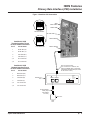
Installing the Aspire T1/PRI Interface PCB (P/N 0891009)
System Requirements:
●
●
●
●
●
T1/PRI Interface PCB, P/N 0891009
Aspire system software: Any Version
NTCPU (P/N 0891002) with PAL Upgrade (P/N 0891039) OR Enhanced NTCPU (P/N 0891038)
For DTMF receivers with such options as ANI/DNIS
CSU/DSU Unit and interconnecting cables (see below)
The T1/PRI PCB has a single 24 channel circuit which you can configure for either T1 trunking or PRI.
When set for PRI, each T1/PRI PCB provides 24 PRI (23 B & 1 D) channels with 64K Clear Channel
response Each PCB uses a single slot in the system cabinet.
Connecting the T1/PRI Interface PCB requires the following equipment.
•
•
•
Satellite 931 CSU (P/N 85945)
External 8-pin RJ-45 crossover cable required
T1/PRI Interface PCB (P/N 92060A)
When installed, the T1/PRI Interface PCB uses the first block of 24 consecutive trunks. For example, if you have
an 8COIU PCB installed for trunks 1-8, the T1/PRI Interface PCB will automatically use trunks 9-32. If you have
8COIU PCBs installed for trunks 1-8 and 17-24, the T1/PRI PCB will use trunks 25-48. The T1/PRI Interface
cannot use trunks 9-16 (even if available) since they are not part of a consecutive block of 24 trunks.
Aspire ISDN PRI Manual
◆ 5
ISDN Features
Primary Rate Interface (PRI) Installation
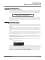
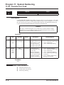
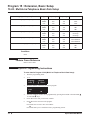
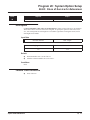
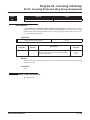
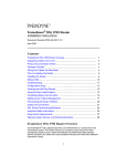
T1/PRI Interface PCB Switches
Switch
Name
Switch
Position
Result
SW100
1.5M(PI/T1)
Connecting a PRI/T1 (1.544Mb/s) line.
2M (PRI/E1)
Connecting a PRI/E1 (2.048Mb/s) line.
T
T-Bus Connection
S
S-Bus Connection
O
2
3
4
N
SW3
(4 bit dip
switch)
1
SW101
1
0
PRI (1.544Mb/s)
3 2 1 0
1
1
0
T1 (1.544Mb/s)
O
2
3
4
N
3 2 1 0
1
O
2
3
4
N
1
0
PRI (2.048Mb/s)
3 2 1 0
1
O
2
3
SW3
(4 bit dip
switch)
(Cont’d)
1
0
E1 (2.048Mb/s)
4
N
3 2 1 0
CN11
6 ◆
Normal
Idle
Loop
Used with Loop Back testing only.
Aspire ISDN PRI Manual
ISDN Features
Primary Rate Interface (PRI) Installation
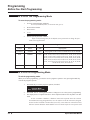
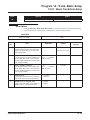
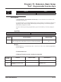
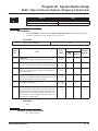
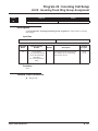
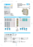
Connector Pin-Outs on T1/PRI PCB
RJ45 Cable Connector - CN3
S-Bus Connection
12345678
Pin No.
Connection
1
TA
2
TB
3
-
4
RA
5
RB
6
-
7
-
8
-
RJ45 Cable Connector - CN3
T-Bus Connection
12345678
Pin No.
Connection
1
RA
2
RB
3
-
4
TA
5
TB
6
-
7
-
8
-
Network Interface Pinout for
the 8-Pin RJ48C Connector
Terminal Interface Pinout for
the 8-Pin RJ48C Connector
For connection to T1
network: Use AT&T
Type ABAM cable or
equivalent (individually-shielded twisted
pair, rated at 100 ohms
at 1 MHz).
Pin No.
Connection
1
RxD (R)
2
RxD (T)
4
TxD (R1)
TxD (T)
5
TxD (T1)
3, 6
No Connection
3, 6
No Connection
7, 8
No Connection
7, 8
No Connection
Pin No.
Connection
1
RxD (R1)
2
RxD (T1)
4
TxD (R)
5
Aspire ISDN PRI Manual
◆ 7
ISDN Features
Primary Rate Interface (PRI) Installation
To install a T1/PRI Interface PCB:
1. Attach a grounded wrist strap to your wrist and a grounded metal object (such as CEU ground).
2. To remove the front cover, loosen the two front panel retaining screws. Slide the front cover to the
right then pull straight out.
3. Set the run/block switch DOWN.
4. Make sure the SW100 switch on the T1/PRI Interface PCB is set to 1.5M (PRI/T1).
5. Set the SW101 dip switches on the T1/PRI PCB for either T-Bus or S-Bus mode.
6. Set the SW3 dip switches on the T1/PRI PCB for either PRI Mode or T1 Mode.
7. Plug the T1/PRI Interface PCB into any universal slot.
Note that the white PCB Pull Tab should always be positioned closest to the top of the cabinet.
8. Set the RUN/BLOCK switch UP.
With normal operation, the status LED will flash fast. If trouble was found during the self diagnostics routine, the status LED will flash slowly.
Once connected, the ISDN Layer Link Status LEDs will be on steady when the Layer link is
established. If there is no link, the LED will be off.
9. Connect the cable from the NT1 Network Termination cable to the CN3 connector on the T1/PRI
PCB.
The CSU connects to the network through an 8-pin RJ45/RJ48 connector. With PRI Networking,
a cross-over cable must be used on the master system’s T1/PRI PCB or CSU to the telco demarcation. If the systems are networked side by side and not through telco, then a straight-through cable
is used.
10. Connecting a Satellite 931 CSU (P/N 85945):
Connect the cable from the T1/PRI PCB to the ‘LOCAL EQUIPMENT’ connector on the
●
back panel of the CSU.
●
Using the 8-pin RJ48C-RJ48C modular cable that was shipped in the box with the Satellite
931 CSU, connect the cable to the ‘T1 NETWORK’ connector on the back panel of the CSU.
●
Connect the opposite end of the NETWORK cable to the telco connection.
11. Replace the cover and tighten the two captive screws on the right side of the cabinet cover.
8 ◆
Aspire ISDN PRI Manual
ISDN Features
Primary Rate Interface (PRI) Installation
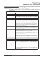
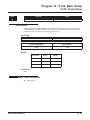
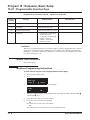
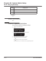
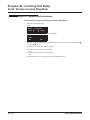
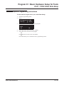
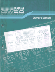
Figure 1: Satellite CSU Connection
1
2
3
4
O N
3 2 1 0
SW2
Block Switch
Status LEDs
PRI Mode Enabled
1
2
3
4
SW100 Switch
Pin #
Circuit Name
1
RxD data (R)
2
RxD data (T)
4
TxD data (R1)
5
TxD data (T1)
3, 6
No connection
7, 8
No connection
O N
Satellite 931 CSU
Terminal Interface Pinout
for 8-Pin RJ48C Connector
3 2 1 0
T1 Mode Enabled
SW101 Switch
See Pin-Out Information
(For connection to T1 Network, use
AT&T Type ABAM cable or equivalent)
(individually-shielded twisted pair, rated
at 100 ohms at 1 Mhz).
Satellite 931 CSU
Network Interface Pinout
for 8-Pin RJ48C Connector
Pin #
Circuit Name
1
RxD data (R1)
2
RxD data (T1)
4
TxD data (R)
5
TxD data (T)
3, 6
No connection
7, 8
No connection
Satellite 931
CSU
POWER
INPUT:
24-48 VDC
.2A MAX.
!
T1
LOCAL (TI)
NETWORK EQUIPMENT
+V
-V
RJ48C-toRJ48C
Cable (ships
with Satellite
931 CSU)
Telco Line
RJ48
Jack
Aspire ISDN PRI Manual
◆ 9
ISDN Features
Primary Rate Interface (PRI) Installation
- For Your Notes -
10 ◆
Aspire ISDN PRI Manual
ISDN Features
Primary Rate Interface (PRI), Answering Calls
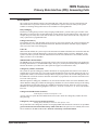
Primary Rate Interface (PRI), Answering Calls
Description
The system provides flexible routing of incoming PRI calls to help meet the exact site requirements. This
allows PRI calls to ring and be answered at any combination of system extensions. Many of the options
available to incoming analog trunk calls are also available to incoming PRI calls.
Delayed Ringing
Extensions in a Ring Group can have delayed ringing for PRI trunks - just like other types of trunks. If the
PRI trunk is not answered at its original destination, it rings the DIL No Answer Ring Group. This could, for
example, help a secretary that covers calls for their boss. If the boss doesn’t answer the call, it rings the secretary’s phone after a programmable time.
Calling Name Delivery
If provided by the telco, and depending on the version of your system software, the system can support calling name delivery in the Facility Information Element. With this information available, display telephone
users can see the name of the calling party.
Caller ID
With Caller ID enabled, the system will provide information for ISDN calls that do not contain the Caller ID
information. If the Caller ID information is restricted, the telephone display will show “PRIVATE”. If the
system is not able to provide Caller ID information because the telco information is not available, then the
display will show “OUT OF AREA”.
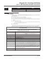
SMDR Includes Dialed Number
The SMDR report can optionally print the trunk’s name (entered in system programming) or the number the
incoming caller dialed (i.e., the dialed ISDN digits). This gives you the option of analyzing the SMDR report
based on the number your callers dial. (This option also applies to a DID trunk as well.)
Calling Party Number Notification
The system can provide calling party number notification for outgoing ISDN calls. When a call is made on
an ISDN line by an extension, the system will send the identification for the extension placing the call, if it’s
programmed. If there is no Extension Calling Number assigned, the system will send the calling number for
the ISDN trunk. If both the extension and trunk information is programmed, the extension information will
be sent as it takes priority.
When the option for calling party subaddress is on, the extension number will be sent as the subaddress information. Both the calling party number and calling party subaddress are sent in a SETUP message as the calling
party information element and a calling party subaddress information element. Allow the system to send the
subaddress by setting the following programs: 10-03-05=1, 15-01-04=1, 20-08-13=1, 21-13-01=enter number
to be sent.
Calling Line Identification Presentation
CLIP display available with software 1.02+.
A Class of Service option has been added which can be used to allow the Calling Party Number IE in the
Setup Message.
Calling Party Allowed or Prevented for Extension
Calling Party allowed for extension with software 1.04+.
The system allows the Calling Party Number for outgoing ISDN calls based on the extension’s set up in Program 15-01-04 : Basic Extension Data Setup - ISDN Caller ID. If this option is to be enabled, then it must
also be enabled for the BRI or PRI PCB in 10-03-05 : PCB Setup - CLIP Information.
Aspire ISDN PRI Manual
◆ 11
ISDN Features
Primary Rate Interface (PRI), Answering Calls
How the Telco Handles PRI Trunks
In many cases, the telco will route an incoming PRI call to any of the available 23 circuits on the PRI PCB.
This makes it difficult to determine the type of call by the trunk that is ringing. It also prevents using Direct
Inward Lines to route incoming calls, since any call sent to the PRI PCB can appear on any circuit. During
programming, set up all trunks on the same PRI PCB in the same way. Refer to Programming below.
To provide more precise routing of PRI trunks, set up PRI Direct Inward Dialing (DID). With DID, the system uses the last three or four digits of the Called Number Information Element to route an incoming call via
the system’s DID translation tables. When programming PRI trunks for DID, refer to the Aspire Software
Manual (P/N 0893200) for additional DID programming.
In addition, in areas where ISDN is not uniformly implemented, many ISDN calls may route to the 3.1 Khz Audio
Ring Group. This can occur if the telco automatically designates a call as 3.1 KHz when it is from a non-ISDN
telephone. To provide uniform treatment of incoming PRI calls, consider having the Ring Group assignments for
both normal PRI calls and 3.1KHz Audio calls. Refer to Programming below for more information.
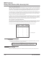
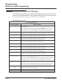
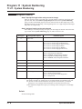
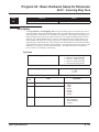
How the Telephone System Handles PRI Trunks
The Channel ID of an incoming SETUP message on a PRI line is related to the trunk group number. The system
will create the trunk line number as the lowest trunk port number in the range of the same trunk group related to
the channel number of the Channel ID information element of an incoming call’s SETUP message.
For example, referring to the chart below, the system translates the call as being trunk port 4.
Trunk
Number
Trunk
Group
Channel
Number
1
1
1
2
1
2
3
1
3
4
2
4
5
2
5
6
2
6
7
2
7
8
5
8
. . . 23
...5
. . . 23
<--- Incoming Call
Conditions
●
PRI requires the installation of a T-Serve II CSU (P/N 85950) or Quad Datasmart DSU (P/N 85956).
Consult your sales representative for more information.
All 23 circuits on the PRI PCB must be identically programmed
since any call sent to the PRI PCB can appear on any circuit.
Default Setting
●
12 ◆
Once set, PRI trunks ring extension 301 and flash at all other extensions just like other trunk calls.
Aspire ISDN PRI Manual
ISDN Features
Primary Rate Interface (PRI), Answering Calls
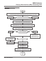
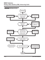
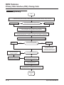
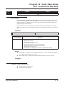
Programming
Start
In 10-03-01, determine the mode of the PRI PCB (0=not set, 1=T-Bus, 2=S-Bus, 3=Network Mode (leased),
4=Network Mode (interconnected), 5=Network Mode (interconnected, fixed layer 1=NT), 6=S-Point.
In 10-03-03, enter '0'.
Is the CRC Multi-Frame (CRC4) used?
No
In 10-03-03, enter '1'.
Yes
In 10-03-04, select the Layer 3 timer type (1-5). The timer value is
set up in Program 81-06 (T-Bus) and 82-06 (S-Bus).
In 10-03-06, determine the length of cable used to connect from the CSU to
the PRI PCB (0=0-40m, 1=40-81m, 2=81-122m, 3=122-162m, 4=162-200m).
(S-Point Only)
In 10-03-07, select the number of DID digits to be received (0-4).
In 10-03-08,
enter '0'.
Is the Dial Sending Mode
Enblock or Overlap Sending?
Enblock
Overlap
In 10-03-08,
enter '1'.
In 10-03-09, select either
Keypad Facility (0) or
Called Party Number (1) for
the dial information element.
In 10-03-10, set the system as
either the slave (0) or
master (1) system.
Yes
Is the system networked?
No
In 10-03-11, set the
system ID number (0-50).
In 10-03-12, select to use either
short-haul (0) or long-haul (1).
In 10-03-13, select the loss-ofsignal detection limit.
In 10-03-14,select the service protocol to be used
(0=keypad facility, 1=specified protocol for Aspire).
Continued on
the following
page.
Aspire ISDN PRI Manual
◆ 13
ISDN Features
Primary Rate Interface (PRI), Answering Calls
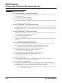
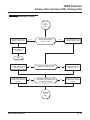
Programming (Cont’d)
Continued from the
previous page.
In 14-05-01, assign PRI lines
to trunk groups (determines available
channels for PRI lines).
In 21-01-03, enter the
interval for the trunk
interdigit timer.
No
Is the amount of time the system
waits before placing the call in a
talk state sufficient?
Yes
In 20-19-04, set the
timer to '0'.
In 20-09-03, set the
extension's COS to '0'.
In 20-13-23, set the
extension's COS to '0'.
Do you wish to have the Caller ID
Name displayed for incoming calls?
No
No
No
Should the sub-address
ID be displayed for
incoming calls?
Should an extension
be able to display the
reason why a call is
transferred to it?
Yes
Yes
In 20-19-04, set the
timer to at least '10'
seconds.
In 20-09-03, set the
extension's COS to '1'.
Yes
In 20-13-23, set the
extension's COS to '1'.
Yes
In 35-02-16, enter '0' to
print the trunk name
assigned in 14-01-01 or
enter '1' to print the
received dialed number.
Define the extension's
Class of Service in 20-06-01.
Is SMDR used?
No
Continued
on next
page.
14 ◆
Aspire ISDN PRI Manual
ISDN Features
Primary Rate Interface (PRI), Answering Calls
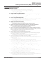
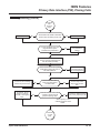
Programming (Cont’d)
Continued from the
previous page.
In 22-02-01, enter 0.
Should all PRI
Trunks ring the same
extensions?
Yes
No
In 22-02-01, enter 3.
Refer to the
Aspire Software
Manual for DID
programming.
In 22-05-01, assign all the trunks on a
PRI PCB to the same Ring Group.
In 14-07-01 and 15-06-01, set up the trunk
Access Maps for PRI trunks.
In 22-04-01, do not
assign extension to PRI
trunk's Ring Group.
Should extension
ring for incoming
calls on PRI trunk?
No
Yes
In 14-01-01, assign names to trunks to
make identification easier.
In 22-01-04,
enter 0.
Do not reroute
Do you want
unanswered PRI
calls to reroute if
unanswered?
Reroute
In 22-04-01, assign extension
to PRI trunk's Ring Group.
For each extension in the Ring
Group, in 22-06-01, enter '1' for
each time mode when the
extension should ring.
In 22-01-04, enter
the DIL No Answer
Time (>0).
In 22-08-01, enter the noanswer Ring Group for
unanswered PRI calls.
In 22-04-01, assign extension
to PRI trunk's Ring No
Answer Ring Group.
Continued on
the following
page.
Aspire ISDN PRI Manual
For each extension in the Ring
Group, in 22-06-01, enter '1' for
each time mode when the
extension should ring.
◆ 15
ISDN Features
Primary Rate Interface (PRI), Answering Calls
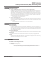
Programming (Cont’d)
Continued from the
previous page.
In 22-01-02, enter 0.
No
If a PRI call rings longer
than a specified interval,
should the ring cadence
change to a unique
"alarm" sound?
Do you want to change the
way PRI calls ring
telephones?
Yes
In 22-01-02, Enter 1.
Also, set the interval in
22-01-03.
Yes
Change the Ring Tone
Range in 22-03-01 and
15-02-02 the tones within
each range in 82-01-01
and the ring
cadence in 20-15-01.
No
In 10-08-01, enter 0
to disable pre-ringing
for trunk calls.
Wait for
ring cycle
For ringing extensions,
should extension ring
when line key starts
flashing or wait for the
system ring cycle?
Adjust the CODEC Gain
in 14-01-02 (transmit)
and 14-01-03 (receive).
Trunks
Do you want to adjust the gain
(volume) for trunks?
When line
key flashes
In 10-08-01, enter 1
to enable pre-ringing
for trunk calls.
Yes
In 15-07-01, program
function keys as line keys
(*01), loop keys (*05) or
line group keys (*02).
No
Consider using loop keys,
Multiple Directory Numbers, or
Ring Groups for PRI trunks
instead of line keys.
Do you want line keys or loop
keys for incoming PRI trunks?
No
Stop
16 ◆
Aspire ISDN PRI Manual
ISDN Features
Primary Rate Interface (PRI), Answering Calls
Programming (Cont’d)
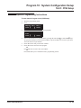
➻ 10-03-01 : PCB Setup - ISDN Line Mode
Setup and confirm the Basic Configuration data for each PCB. This program selects the ISDN Line
Mode: 0=Not set, 1=T-Bus, 2=S-Bus, 3=Network Mode (Leased Line), 4=Network Mode (Interconnected Line), 5=Network Mode (Interconnected Line, Fixed Layer 1=NT), 6=S-Point (Leased Line).
The option selected here determines the clock source for a networked system. With option 3, telco
sends the clock to the master and slave systems. With option 4, the master system sends the clock to
telco which then sends the clock to the slave system (with no telco, the master system sends the clock
directly to the slave system). With option 5, the master and slave systems both send the clock to telco.
Default Setting: T-Bus (1).
➻
➻
➻
➻
➻
➻
➻
➻
10-03-02 : PCB Setup - Logical Port Number
Setup and confirm the Basic Configuration data for each PCB. This program displays the start port
number of a PRI line. Thirty logic ports are automatically assigned to a PRI line (T-Bus = 1-200, S-Bus
= 1-256).
Default Setting: (0).
10-03-03 : PCB Setup - CRC Multi-Frame (CRC4)
Setup and confirm the Basic Configuration data for each PCB. This program determines whether or not
the CRC Multi-Frame (CRC4) is used (0=off, 1=on).
Default Setting: Off (0).
10-03-04 : PCB Setup - Layer 3 Timer Type
Setup and confirm the Basic Configuration data for each PCB. This program selects the Layer 3 timer
type (1-5). Each timer value of Layer 3 is set up for each type in Program 81-06 (T-Bus) and Program
82-06 (S-Bus).
Default Setting: Layer 3 Timer Type (1).
10-03-06 : PCB Setup - Length of Cable
Setup and confirm the Basic Configuration data for each PCB. Select the length of cable to be used
(0=0-40m, 1=40-81m, 2=81-122m, 3=122-162m, 4=162-200m).
Default Setting: Cable Length 40-81m (1).
10-03-07 : PCB Setup - S-Point DID Digits
Setup and confirm the Basic Configuration data for each PCB. This program selects number of DID
digits to be received (0-4).
Default Setting: Number of DID Digits (0).
10-03-08 : PCB Setup - Dial Sending Mode
Setup and confirm the Basic Configuration data for each PCB. Select either enblock or overlap sending
(0=Enblock Sending, 1=Overlap Sending).
Default Setting: Enblock Sending (0).
10-03-09 : PCB Setup - Dial Information Element
Setup and confirm the Basic Configuration data for each PCB. If Overlap Sending is selected in Program 10-03-08, select either Keypad Facility (0) or Called Party Number (1) for the dial information
element.
Default Setting: Keypad Facility (0).
10-03-10 : PCB Setup - Master/Slave System
Setup and confirm the Basic Configuration data for each PCB. If the system is networked, set the system as either the slave (0) or master (1) system.
Default Setting: Slave System (0).
Aspire ISDN PRI Manual
◆ 17
ISDN Features
Primary Rate Interface (PRI), Answering Calls
Programming (Cont’d)
➻ 10-03-11 : PCB Setup - Networking System Number
➻
➻
➻
➻
➻
➻
➻
➻
➻
18 ◆
Setup and confirm the Basic Configuration data for each PCB. If the system is networked, define the
system number (0-50).
Default Setting: System Number (0).
10-03-12 : PCB Setup - Short/Long Haul
Setup and confirm the Basic Configuration data for each PCB. Select either short-haul (0) or long-haul
(1).
Default Setting: Short-Haul (0).
10-03-13 : PCB Setup - Loss-of-Signal Detection Limit
Setup and confirm the Basic Configuration data for each PCB. Select the loss-of-signal detection limit.
In short-haul mode: 0=0.91V, 1=0.74V, 2=0.59V, 3=0.42V, 4=0.32V, 5=0.21V, 6=0.16V. 7=0.10V.
In long-haul mode: 0=1.70V, 1=0.84V, 2=0.84V, 3=0.45V, 4=0.45V, 5=0.20V, 6=0.10V, 7=not defined.
Default Setting: 0.91V (0).
10-03-14 : PCB Setup - Service Protocol for S-Point
Setup and confirm the Basic Configuration data for each PCB. Select the service protocol to be used
(0=keypad facility, 1=specified protocol for Aspire).
Default Setting: Keypad Facility (0).
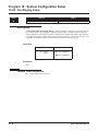
10-08-01 : Pre-ringing Setup
Enable (1) or disable (0) pre-ringing for outside calls. Refer to the Aspire Software Manual for more
information.
Default Setting: Pre-ringing disabled (0).
14-01-01 : Basic Trunk Data Setup - Trunk Names
Assign names to trunks to make identifying incoming calls easier. Keep in mind that with certain
telco’s you may not be able to correlate the type of PRI call with specific trunk.
Default Setting: Trunk names are the same as the line number (ex: Line 001).
14-01-02 : Basic Trunk Data Setup - Transmit CODEC Gain Type
If required, adjust the transmit CODEC gains for each trunk.
Default Setting: 1 (0 dB transmit gain)
14-01-03 : Basic Trunk Data Setup - Receive CODEC Gain Type
If required, adjust the transmit CODEC gains for each trunk.
Default Setting: 1 (0 dB receive gain)
14-05-01 : Trunk Groups
Assign the PRI trunks to trunk groups. This determines the channels available for PRI lines.
Default Setting: All trunks assigned to Trunk Group 1.
14-07-01 : Trunk Access Map Setup
Set up Trunk Access Maps (200) for PRI trunks. You must also assign extensions to Trunk Access
Maps in Program 15-06-01. Note that for incoming calls, Ring Group programming overrides Access
Map programming. See How the Telco Handles PRI Trunks on page 12 for more.
Default Setting: All trunks in Access Map 1 have full access (7). All trunks in the other Access
Maps have no access (0).
Aspire ISDN PRI Manual
ISDN Features
Primary Rate Interface (PRI), Answering Calls
Programming (Cont’d)
➻ 15-02-02 : Multi-Line Telephone Basic Data Setup - Trunk Ring Tone
➻
➻
➻
➻
➻
➻
➻
➻
➻
➻
➻
Use this option to change the ringing pitch of incoming trunk calls to keysets.
Default Setting: Midrange (2)
15-06-01 : Trunk Access Map for Extensions
Assign Trunk Access Maps (200) to extensions. You must set up the Trunk Access Maps in Program
14-07-01. See How the Telco Handles PRI Trunks on page 12 for more.
Default Setting: All extensions use Access Map 1.
15-07-01 : Programmable Function Keys
To have incoming PRI calls ring specific keys, assign trunks to line keys (*01 + line # [001-200]). You
can also have loop keys (code *05) and Trunk Group keys (code *02 + Trunk Group).
Default Setting: Function keys 1-12 are line keys for trunks 1-12.
20-06-01 : Class of Service for Extensions
Assign a Class of Service (1-15) to an extension.
Default Setting: Extension 301 has COS 15. All other extension have COS 1.
20-09-03 : Class of Service Options (Incoming Call Service) - Sub-Address Identification
Enable (1) or disable (0) the telco’s ability to display the sub-address identification.
Default Setting: ISDN Sub-Address Identification disabled (0).
20-13-23 : Class of Service Options (Supplementary Service) - Display the Reason for Transfer
Enable (1) or disable (0) an extension’s ability to display the reason (Call Forward, Busy, No Answer or
DND) a VRS, DID, DISA, or ISDN call is being transferred to their extension.
Default Setting: No reason is displayed (0).
20-15-01 : Ring Cycle Setup - Normal Incoming Call on Trunk
Use this option to change the way calls ring the telephones. Keep in mind that changing this option
affects all types of trunk calls - not just PRI calls.
Default Setting: Outside calls ring keysets with a short ring followed by a pause (3).
20-19-04 : System options for Caller ID - Wait Facility IE Timer
This option sets how long the system will wait for the Caller ID name (0-64800 seconds). If set to “0”
no name is provided.
Default Setting: 10 seconds.
21-01-03 : System Options for Outgoing Calls - Trunk Interdigit Time (External)
Set the amount of time the system must wait before placing the call in a talk state (call isn't timed until
then, Voice Over and Barge-In are not allowed until after timer expires) (0-64800 seconds).
Default Setting: Trunk Interdigit = 5 seconds.
22-01-02 : System Options for Incoming Calls - Incoming Call Ring No Answer Alarm
Enable (1) or disable (0) the Incoming Call RNA Alarm. If enabled, the ring cadence will change for a
call that rings longer than the interval set in Program 22-01-03.
Default Setting: Incoming Ring No Answer Alarm disabled (0).
22-01-03 : System Options for Incoming Calls - Ring No Answer Alarm Time
Set the Ring No Answer Alarm interval (0-64800 seconds). If a trunk rings a keyset longer than this
interval, the system changes the ring cadence, if enabled in 22-01-02.
Default Setting: Ring No Answer Alarm Time = 60 seconds.
22-01-04 : System Options for Incoming Calls - DIL No Answer Recall Time
If an incoming trunk call rings longer than this interval, it reroutes to the Ring Group set in Program 22-08.
Default Setting: DIL No Answer Time disabled (0). Calls do not reroute.
Aspire ISDN PRI Manual
◆ 19
ISDN Features
Primary Rate Interface (PRI), Answering Calls
Programming (Cont’d)
➻ 22-02-01 : Incoming Call Trunk Setup
➻
➻
➻
➻
➻
➻
20 ◆
Use this option to set the service type for PRI trunks using. Enter 0 (for normal operation) or 3 (to have
the PRI trunk use the DID tables and route on the last three digits a caller dials). There is one item for
each Night Service Mode.
Default Setting: All trunk service types set for normal (0).
22-03-01 : Trunk Ring Tone Range
Assign Ring Tone Ranges to trunks. Customize the tones within each Ring Tone Range in Program 8201. Trunks ring extensions according to the Ring Tone Range selected in 22-03 and the user settings
made with Service Code 820. You may want your ISDN trunks to ring with a unique ring tone.
Default Setting: Pattern 0.
22-04-01 : Incoming Extension Ring Group Assignment
To have PRI trunks ring extensions, use this program to assign extensions (up to 32 max.) to Ring
Groups (1-100). You must also assign the PRI trunks to the Ring Groups in Program 22-05 below. See
How the Telco Handles PRI Trunks on page 12 for more.
Default Setting: All extensions are in Ring Group 1.
22-05-01 : Incoming Trunk Ring Group Assignment
To have PRI trunks ring extensions, assign trunks to Ring Groups (Ring Groups =1-100, 102 = In-Skin/
External Voice Mail, 103 = Centralized Voice Mail). Normally, you should assign a trunk on a PRI PCB
to the same Ring Group. You must also assign extensions to Ring Groups in Program 22-04-01 above.
See How the Telco Handles PRI Trunks on page 12 for more.
Default Setting: All trunks are in Ring Group 1.
22-06-01 : Normal Incoming Ring Mode
For each extension in the Ring Group assigned in 22-04-01, indicate if trunks should ring (1) or not
ring (0).
Default Setting: All extensions ring.
22-08-01 : DIL/IRG No Answer Destination
If an incoming PRI trunk call rings longer than the DIL No Answer Time (Program 22-01-04), it routes to
the Ring Group you specify in this option (Ring Groups=1-100, In-Skin/External Voice Mail = 102, Centralized Voice Mail = 103).
Default Setting: Calls reroute to Ring Group 1 based on the timer in Program 22-01-04.
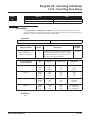
22-11-01 : DID Translation Table Number Conversion
Specify for each Translation Table entry (2000):
● The digits received by the system (eight max.)
● The extension the system dials after translation (24 digits max.)
● The name that should show on the dialed extension’s display when it rings (twelve characters max.)
● The Transfer Target-1 and 2
● If the Transfer Targets are busy or receive no answer, those calls are transferred to the final
transfer destination (Program 22-10).
● Operation mode
Aspire ISDN PRI Manual
ISDN Features
Primary Rate Interface (PRI), Answering Calls
Programming (Cont’d)
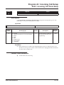
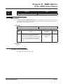
➻ 35-02-16 : SMDR Output Options, Trunk Name or Received Dialed Number
➻
If SMDR is used, this option allows you to determine how the SMDR should print incoming calls on
ANI/DNIS or DID trunks (0=print trunk port name assigned in Program 14-01-01, 1=print received
dialed number). On ANI/DNIS trunks, if enabled, the DNIS digits can be printed instead of the trunk
name. If a call is received on a DID trunk, the received number can be printed. If the received number
is not in the DID Translation Table (Program 22-11-01), then no number is printed. On ISDN trunks,
the called party number can be printed for DID’s, if desired.
Default Setting: Print Trunk Port Name (0).
82-01-01 : Incoming Ring Tone
Customize the incoming ring tone (the tones a user hears when a call rings an extension). Trunks ring
extensions according to the Ring Tone Range selected in 22-03-01 and the user settings made with Service Code 820.
Default Setting: Refer to Program 82-01-01 in the Software Manual.
Related Features
Direct Inward Dialing
Use DID to control the inbound routing of PRI trunks. With DID, the system will use the last three or
four digits of the Called Number Information Element to route an incoming call via the DID translation
tables. When programming PRI lines for DID, refer to the Aspire Software Manual (P/N 0893200) for
further programming information.
Forced Trunk Disconnect
This feature only works on analog trunk. ISDN trunks do not have the Forced Trunk Disconnect available.
Night Service
If enabled, an extension user can dial the Universal Answer code to pick up a ringing PRI trunk.
Transfer
Transferred calls on DISA, DID, ISDN trunks, or from the VRS can display the reason a call is being
transferred (Call Forward, Busy, No Answer, or DND).
Operation
To answer an incoming trunk call:
1.
2.
Lift handset.
At keyset, press flashing line key.
If you don’t have a line or loop key for a PRI call ringing your phone, it rings an idle
CALL key. If you have Ringing Line Preference, lifting the handset answers the call.
Aspire ISDN PRI Manual
◆ 21
ISDN Features
Primary Rate Interface (PRI), Answering Calls
- For Your Notes -
22 ◆
Aspire ISDN PRI Manual
ISDN Features
Primary Rate Interface (PRI), Placing Calls
Primary Rate Interface (PRI), Placing Calls
Description
The system provides 23 high-speed state-of-the-art digital trunks on a double pair of wires.
!! Important !!
Primary Rate Interface (PRI) requires additional programming. Refer to
the Programming section for more information.
Conditions
PRI requires the installation of a CSU/DSU Unit and interconnecting cables. Consult with your sales
representative for more information.
Default Setting
●
Once set, users can place calls over PRI trunks.
Aspire ISDN PRI Manual
◆ 23
ISDN Features
Primary Rate Interface (PRI), Placing Calls
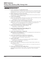
Programming
Start
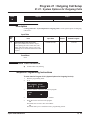
In 10-03-01, determine the mode of the PRI PCB (0=not set, 1=T-Bus, 2=S-Bus, 3=Network Mode (leased),
4=Network Mode (interconnected), 5=Network Mode (interconnected, fixed layer 1=NT), 6=S-Point.
In 10-03-03, enter '0'.
Is the CRC Multi-Frame (CRC4) used?
No
In 10-03-03, enter '1'.
Yes
In 10-03-04, select the Layer 3 timer type (1-5). The timer value is
set up in Program 81-06 (T-Bus) and 82-06 (S-Bus).
In 10-03-06, determine the length of cable used to connect from the CSU to
the PRI PCB (0=0-40m, 1=40-81m, 2=81-122m, 3=122-162m, 4=162-200m).
In 10-03-07, select the number of DID digits to be received (0-4).
In 10-03-08,
enter '0'.
Is the Dial Sending Mode
Enblock or Overlap Sending?
Enblock
Overlap
In 10-03-08,
enter '1'.
In 10-03-09, select either
Keypad Facility (0) or
Called Party Number (1) for
the dial information element.
In 10-03-10, set the system as
either the slave (0) or
master (1) system.
Yes
Is the system networked?
No
In 10-03-11, set the
system ID number (0-50).
In 10-03-12, select to use either
short-haul (0) or long-haul (1).
In 10-03-13, select the loss-ofsignal detection limit.
In 10-03-14,select the service protocol to be used
(0=keypad facility, 1=specified protocol for Aspire).
Continued on
the following
page.
24 ◆
Aspire ISDN PRI Manual
ISDN Features
Primary Rate Interface (PRI), Placing Calls
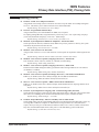
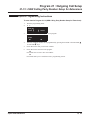
Programming (Cont’d)
Continued
from
previous
page.
In 20-08-02, enter 0 to
disable outgoing calls.
No
Should system users be
able to place outgoing
calls on trunks?
Yes
In 20-08-02, enter 1 to
enable outgoing calls.
In 20-06-01, assign
Class of Service to
extensions.
Stop
In 20-08-13, enter 0 to
disable calling number
display by telco.
No
Should telco display the calling
number for outgoing calls?
Yes
In 20-08-13, enter 1 to
enable calling number
display by telco.
In 20-13-31, enter 0 to
disable trunk ID display
by telco.
No
Should telco display the trunk
identification for outgoing calls
the extension places?
Yes
In 20-13-31, enter 1 to
enable trunk ID display
by telco.
Continued
on next
page.
Aspire ISDN PRI Manual
◆ 25
ISDN Features
Primary Rate Interface (PRI), Placing Calls
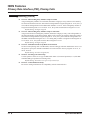
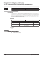
Programming (Cont’d)
Continued
from
previous
page.
In 15-01-04, enter 0.
In 10-03-05 enter 0.
No
Should Caller ID be included in
the call's setup message?
Yes
In 15-01-04, enter 1.
In 10-03-05 enter 1.
In 20-09-03, enter 0 to
disable sub-address
display by telco.
No
Should telco display the calling
number's sub-address?
Yes
In 20-09-03, enter 1 to
enable sub-address
display by telco.
In 1005, assign
Class of Service to
extensions.
In 21-12-01, program the calling party number
data (15 digits max.) for each trunk.
In 21-13-01, program the calling party number
data (15 digits max.) for each extension.
In 14-01-07, enter 0 to
prevent outgoing calls.
No
Are outgoing
calls allowed on
specific trunks?
In 14-01-07, enter 1 to
allow outgoing calls.
Yes
In 14-05-01 assign PRI trunks to trunk groups
(This determines available channels for PRI
trunks).
Build an outgoing restriction matrix.
In the default program,
extensions have full
access to all trunks.
Do you need to restrict certain
extensions from placing calls on
certain trunks?
Yes
In 14-07-01 for each
Access Map, select
the access options
for each trunk.
No
Continued
on next
page.
26 ◆
In 15-06-01, assign
extensions to
Access Maps.
Aspire ISDN PRI Manual
ISDN Features
Primary Rate Interface (PRI), Placing Calls
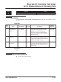
Programming (Cont’d)
Continued
from
previous
page.
In 14-01-10, enter 0.
Should caller hear DTMF confirmation
tones as they are dialing a trunk call?
No
If a user preselects a line, how
long should the system
remember the preselection?
Yes
In 14-01-10, enter 1.
Yes
In 20-02-06, enter
the preselection
interval.
No
In 21-01-03, enter
the interval for the
trunk interdigit timer.
No
If the system detects the called party
is busy, how long should the busy
tone be heard? (0-64800)
Is the amount of time the system
waits before placing the call in a
talk state sufficient?
Yes
In 15-07-01, do not assign
function keys as line keys.
In 15-07-01, do not
assign Trunk Group
Access or trunk group
keys.
No
No
Should extension users
have one-button placing
of outside calls?
Yes
In 15-07-01, assign
function keys as line
keys (code *01+001200).
Should extension users have
one-button access to trunk
groups for placing calls?
Yes
In 15-07-01, assign loop keys
(*05) or line group keys (*02).
See "Loop Key" in the
software manual for more
details.
Continued
on next
page.
Aspire ISDN PRI Manual
◆ 27
ISDN Features
Primary Rate Interface (PRI), Placing Calls
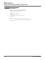
Programming (Cont’d)
Continued
from
previous
page.
Adjust the CODEC Gain
in 14-01-02 (transmit)
and 14-01-03 (receive).
Trunks
Do you want to adjust
the gain (volume) for
trunks?
No
Check the Analog Trunk Timers in 81-01
for compatibility with the telco.
For example, to make
50 the Alternate Trunk
Route Access Code:
DIAL = 5
Digit = 2
Kind = 8
If desired, assign names to trunks in
14-01-01.
Stop
Do you want to set up
an Alternate Trunk
Route Access Code ?
No
Yes
In 11-01-01, set up a
Service Code for
Alternate Trunk Route
Access.
No
In 21-15-01, enter the
extension number
and enter 0 to
prevent routing.
In 11-09-02, assign the
Service Code set up in the
previous step for Alternate
Trunk Route Access.
In 21-15-01, enter the
extension number and
enter the Trunk Group
Routing route number.
Yes
Should extension
be able to use
Alternate Trunk
Route Access?
Refer to the Trunk
Group Routing feature
and set up Trunk
Group Routing.
No
Is Trunk Group
Routing defined?
Yes
Stop
28 ◆
Aspire ISDN PRI Manual
ISDN Features
Primary Rate Interface (PRI), Placing Calls
Programming (Cont’d)
➻ 10-03-01 : PCB Setup - ISDN Line Mode
Setup and confirm the Basic Configuration data for each PCB. This program selects the ISDN Line
Mode: 0=Not set, 1=T-Bus, 2=S-Bus, 3=Network Mode (Leased Line), 4=Network Mode (Interconnected Line), 5=Network Mode (Interconnected Line, Fixed Layer 1=NT), 6=S-Point (Leased Line).
The option selected here determines the clock source for a networked system. With option 3, telco
sends the clock to the master and slave systems. With option 4, the master system sends the clock to
telco which then sends the clock to the slave system (with no telco, the master system sends the clock
directly to the slave system). With option 5, the master and slave systems both send the clock to telco.
➻
10-03-02 : PCB Setup - Logical Port Number
Setup and confirm the Basic Configuration data for each PCB. This program displays the start port
number of a PRI line. Thirty logic ports are automatically assigned to a PRI line (T-Bus = 1-200, S-Bus
= 1-256).
➻
10-03-03 : PCB Setup - CRC Multi-Frame (CRC4)
Setup and confirm the Basic Configuration data for each PCB. This program determines whether or not
the CRC Multi-Frame (CRC4) is used (0=off, 1=on).
➻
10-03-04 : PCB Setup - Layer 3 Timer Type
Setup and confirm the Basic Configuration data for each PCB. This program selects the Layer 3 timer
type (1-5). Each timer value of Layer 3 is set up for each type in Program 81-06 (T-Bus) and Program
82-06 (S-Bus).
➻
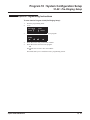
10-03-05 : PCB Setup - CLIP Information
Based on this setting, the system will include a “Presentation Allowed” (1) or “Presentation Restricted”
(0) in the Setup message to allow or deny the Calling Party Number. Program 15-01-04 must also be
set to a ‘1’ if this option is enabled.
➻
10-03-06 : PCB Setup - Length of Cable
Setup and confirm the Basic Configuration data for each PCB. Select the length of cable to be used
(0=0-40m, 1=40 81m, 2=81-122m, 3=122-162m, 4=162-200m).
➻
10-03-07 : PCB Setup - S-Point DID Digits
Setup and confirm the Basic Configuration data for each PCB. This program selects number of DID
digits to be received (0-4).
➻
10-03-08 : PCB Setup - Dial Sending Mode
Setup and confirm the Basic Configuration data for each PCB. Select either enblock or overlap sending
(0=Enblock Sending, 1=Overlap Sending).
➻
10-03-09 : PCB Setup - Dial Information Element
Setup and confirm the Basic Configuration data for each PCB. If Overlap Sending is selected in Program 10-03-08, select either Keypad Facility (0) or Called Party Number (1) for the dial information
element.
➻
10-03-10 : PCB Setup - Master/Slave System
Setup and confirm the Basic Configuration data for each PCB. If the system is networked, set the system as either the slave (0) or master (1) system.
➻
10-03-11 : PCB Setup - Networking System Number
Setup and confirm the Basic Configuration data for each PCB. If the system is networked, define the
system number (0-50).
➻
10-03-12 : PCB Setup - Short/Long Haul
Setup and confirm the Basic Configuration data for each PCB. Select either short-haul (0) or long-haul
(1).
Aspire ISDN PRI Manual
◆ 29
ISDN Features
Primary Rate Interface (PRI), Placing Calls
Programming (Cont’d)
➻ 10-03-13 : PCB Setup - Loss-of-Signal Detection Limit
Setup and confirm the Basic Configuration data for each PCB. Select the loss-of-signal detection limit.
In short-haul mode: 0=0.91V, 1=0.74V, 2=0.59V, 3=0.42V, 4=0.32V, 5=0.21V, 6=0.16V. 7=0.10V. In
long-haul mode: 0=1.70V, 1=0.84V, 2=0.84V, 3=0.45V, 4=0.45V, 5=0.20V, 6=0.10V, 7=not defined
➻
10-03-14 : PCB Setup - Service Protocol for S-Point
Setup and confirm the Basic Configuration data for each PCB. Select the service protocol to be used
(0=keypad facility, 1=specified protocol for Aspire).
➻
11-01-01 : System Numbering
Set up a Service Code for Alternate Trunk Route Access. You may want to use an alternate access code
for your outgoing PRI trunks. Also see programs 11-09-02 and 21-15-01.
Default Setting: No Alternate Trunk Route Access code programmed.
➻
11-09-02 : Trunk Access Code - Alternate Trunk Route Access Code
Assign the Service Code set up in 11-01-01 for Alternate Trunk Route Access. You may want to use an
alternate access code for your outgoing PRI trunks. Also see programs 11-01-01 and 21-15-01.
Default Setting: No Alternate Trunk Route Access code programmed.
14-01-02 : Basic Trunk Data Setup - Transmit CODEC Gain Type
If required, adjust the transmit CODEC gains for each trunk.
Default Setting: 1 (0 dB transmit gain)
14-01-03 : Basic Trunk Data Setup - Receive CODEC Gain Type
If required, adjust the transmit CODEC gains for each trunk.
Default Setting: 1 (0 dB receive gain)
14-01-07 : Basic Trunk Port Setup - Outgoing Calls
Allow this option (1) for each PRI trunk you want to use for outgoing calls. Prevent this option (0) if
the trunk will not be used for outgoing calls.
Default Setting: Outgoing calls allowed (1).
14-01-10 : Basic Trunk Data Setup - DTMF Tones for Outgoing Calls
For each trunk, enable (1) or disable (0) DTMF tones for outgoing trunk calls.
Default Setting: DTMF tone disabled for outgoing calls (0).
14-05-01 : Trunk Groups
Assign the PRI trunks to trunk groups. This determines the channels available for PRI lines.
Default Setting: All trunks assigned to Trunk Group 1.
14-07-01 : Trunk Access Map Setup
Set up Trunk Access Maps (200) for PRI trunks. You must also assign extensions to Trunk Access
Maps in Program 15-06-01.
Default Setting: All trunks in Access Map 1 have full access (7). All trunks in the other Access
Maps have no access (0).
15-01-04 : Basic Extension Data Setup - ISDN Caller ID
If both Program 15-01-04 and 10-03-05 are enabled (1), the system includes Caller ID in the Setup
message as “Presentation Allowed”. If these options are disabled (0), it will be “Presentation
Restricted”.
➻
➻
➻
➻
➻
➻
➻
30 ◆
Aspire ISDN PRI Manual
ISDN Features
Primary Rate Interface (PRI), Placing Calls
Programming (Cont’d)
➻ 15-06-01 : Trunk Access Map for Extensions
➻
➻
➻
➻
➻
➻
➻
➻
➻
Assign Trunk Access Maps (200) to extensions. You must set up the Trunk Access Maps in Program
14-07-01. This allows you to control extension access to the PRI trunks.
Default Setting: All extensions use Access Map 1.
15-07-01 : Programmable Function Keys
Assign a function key for Caller ID Block for ISDN (63) if required.
To simplify placing PRI calls, assign function keys as line keys (*01 + line # [001-200]), loop keys
(code 1078) and Trunk Group keys (code 1012 + Trunk Group).
Default Setting: Function keys 1-12 are line keys for trunks 1-12.
20-02-06 : System Options for Multi-Line Telephones - Preselection Time
Set the preselection interval (0-64800 seconds). When a keyset user preselects a line key, the system
remembers the preselection for this interval.
Default Setting: Preselection time is 5 seconds.
20-06-01 : Class of Service for Extensions
Assign a Class of Service (1-15) to each extension. Use this option in conjunction with Program 20-0802.
Default Setting: Extension 301 has COS 15. All other extension have COS 1.
20-08-02 : Class of Service Options (Outgoing Call Service) - Trunk Calls
In an extension’s Class of Service, enable (1) or disable (0) trunk calling.
Default Setting: Trunk calling enabled (1).
20-08-13 : Class of Service Options (Outgoing Call Service) - ISDN CLIP
Determine if the ISDN calling line identity presentation and screening indicators are to be allowed
(0=disabled, 1=enabled).
Default Setting: ISDN Calling Party Number disabled (0).
20-09-03 : Class of Service Options (Incoming Call Service) - Sub-Address Identification
Enable (1) or disable (0) the telco’s ability to display the sub-address identification.
Default Setting: ISDN Sub-Address Identification disabled (0).
20-13-31 : Class of Service Options - ISDN Connected Line Identification
Enable (1) or disable (0) the telco’s ability to display trunk identification for outgoing calls the extension places.
Default Setting: ISDN Connected Line Identification disabled (0).
21-01-03 : System Options for Outgoing Calls - Trunk Interdigit Time (External)
Set the amount of time the system must wait before placing the call in a talk state (call isn't timed until
then, Voice Over and Barge-In are not allowed until after timer expires) (0-64800 seconds).
Default Setting: Trunk Interdigit = 5 seconds.
21-08-04 : Repeat Dial Setup - Time for Send Busy Tone for ISDN Trunk
Set the length of the time the system should send a busy tone after detecting the called party is busy (by
receiving either a 'RELease complete' or 'DISConnect' message from the CO). After this timer's
expires, the keyset will go to an idle status (0-64800 seconds). If '0' is entered, a caller will not hear a
busy tone when the ISDN trunk detects a busy state. It will immediately go the an idle status.
Default Setting: 0 (caller does not hear busy tone)
Aspire ISDN PRI Manual
◆ 31
ISDN Features
Primary Rate Interface (PRI), Placing Calls
Programming (Cont’d)
➻ 21-12-01 : ISDN Calling Party Number Setup for Trunks
➻
➻
➻
➻
32 ◆
Assign Calling Party Numbers for each trunk (maximum 16 digits per entry). When a call is made by
an extension which does not have an Extension Calling Number assigned (Program 21-13-01), the system sends the calling number for the ISDN trunk defined in 21-12-01. If the Calling Party Number is
assigned in both Programs 21-12-01 and 21-13-01, the system sends the data in Program 21-13-01.
Default Setting: No digits assigned.
21-13-01 : ISDN Calling Party Number Setup for Extensions
Assign each extension a Calling Party Number (maximum 16 digits per entry). The calling number is
the subscriber number of the dial-in number. When a call is made by an extension which does not have
an Extension Calling Number assigned (Program 21-12-01), the system sends the calling number for
the ISDN trunk defined in Program 21-13. If a Calling Party Number is assigned in both Programs 2112-01 and 21-13-01, the system sends the data in Program 21-12-01.
Default Setting: No digits assigned.
21-15-01 : Individual Trunk Group Route for Extensions
To better control placing calls over PRI trunks, consider setting up Alternate Trunk Route Access. Use
this option to specify the Alternate Trunk Route for each extension. Also see programs 11-01-01, 1109-02, 14-06-01.
Default Setting: No routes assigned (00).
22-02-01 : Incoming Call Trunk Setup
Use this option to set the service type for PRI trunks. Enter 0 (for normal operation) or 3 (if the PRI
trunk has DID type operation for incoming calls).
Default Setting: All trunk service types set for normal (0).
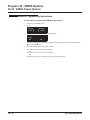
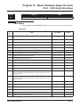
81-01-01 : COIU Initial Data Setup
Review the Analog Trunk Timers for compatibility with the connected telco.
Aspire ISDN PRI Manual
ISDN Features
Primary Rate Interface (PRI), Placing Calls
Related Features
Handsfree
With Automatic Handsfree, an extension user can press a line key to place a trunk call without first lifting the handset or pressing SPK. Users without Automatic Handsfree can preselect a line key before
lifting the handset or pressing SPK.
Repeat Redial
Repeat Dial on ISDN trunks do not use the system timer 21-08-03 : Repeat Dial Setup - Repeat Dial
Calling Timer. The ISDN trunks can detect whether the call was busy or answered.
Repeat Dial on an analog trunk does not use this system timer 21-08-04 : Repeat Dial Setup - Time for
Send Busy Tone for ISDN Trunk.
Operation
To place a PRI call over a trunk group:
1.
2.
3.
4.
At keyset, press idle CALL key.
OR
At single line set, lift handset.
Dial 804.
Dial PRI trunk group number (001-200).
Dial number.
OR
At keyset, press trunk group key (PGM 15-07 or SC 852: *02 + group).
Also see the “Loop Keys” feature in the Software Manual.
2. Dial number.
Dialing # after the telephone number will speed up the dialing on PRI lines.
1.
To place a PRI call using Trunk Group Routing:
1.
2.
3.
At keyset, press idle CALL key.
OR
At single line set, lift handset.
Dial 9.
If your system has an Alternate Trunk Route Access code for PRI trunks, you may dial that
instead.
Dial number.
OR
At keyset, press Trunk Group Routing key (PGM 15-07 or SC 852: *02).
Also see the “Loop Keys” feature in the Software Manual.
2. Dial number.
1.
Aspire ISDN PRI Manual
◆ 33
ISDN Features
Primary Rate Interface (PRI), Placing Calls
Operation (Cont’d)
To place a call over a specific PRI trunk:
1.
2.
3.
4.
At keyset, press idle CALL key.
OR
At single line set, lift handset.
Dial #9.
Dial line PRI line number (e.g., 005 for line 5).
Dial number.
OR
At keyset, press line key (PGM 15-07 or SC 851: 001 to 200).
Also see the “Loop Keys” feature in the Software Manual.
2. Dial number.
1.
34 ◆
Aspire ISDN PRI Manual
Section 2
ISDN PRI Programming
Section 2
ISDN PRI Programming
Section 2:
ISDN PRI Programming
Aspire ISDN PRI Manual
◆ 35
Section 2
ISDN PRI Programming
36 ◆
Aspire ISDN PRI Manual
Programming
Before You Start Programming
Programming
Before You Start Programming
Before Reading This Section
This section provides you with detailed information about the system programs. By changing a program,
you change the way the feature associated with that program works. In this section, you’ll find out about
each program, the features that the program affects and how to enter the program data into system memory.
Do not start customizing your system without first
reading “Section 1, ISDN PRI Features”.
When you want to customize a feature, find it in Section 1 and learn about it. Section 1 will tell you what
programs you have to change to get the operation you want. Make a note of the changes on the Program
Record Forms provided with your system. Then, look the program up in this section if you have any questions about how to enter the data.
How to Use This Section
This section lists each program in numerical order. For example, Program 10-01 is at the beginning of the
section and Program 92-01 is at the end. The information on each program is subdivided into the following
headings:
Description describes what the program options control. The Default Settings for each program are also
included. When you first install the system, it uses the Default Setting for all programs. Along with the
Description are the Conditions which describe any limits or special considerations that may apply to the program.
The reverse type (white on black) just beneath the Description heading is the program’s access level. You can
only use the program if your access level meets or exceeds the level the program requires. Refer to How to
Enter the Programming Mode (page 38) for a list of the system’s access levels and passwords.
Feature Cross Reference provides you with a table of all the features affected by the program. You’ll want
to keep the referenced features in mind when you change a program. Customizing a feature may have an
effect on another feature that you didn’t intend.
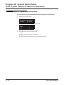
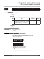
Telephone Programming Instructions shows you how to enter the program’s data into system memory.
For example:
1. Enter the programming mode.
2. 15-07-01
15-07-01 TEL301
KY01 = *01
←
→
tells you to enter the programming mode, dial 150701 from the telephone dial pad. After you do, you’ll see
the message “15-07-01 TEL301” on the first line of the telephone display. This indicates the program number (15-07), item number (01), and that the options are being set for extension 301. The second row of the
display “KY01 = *01” indicates that Key 01 is being programmed with the entry of *01. The third row
allows you to move the cursor to the left or right, depending on which arrow is pressed. To learn how to enter
the programming mode, see How to Enter the Programming Mode below.
Aspire ISDN PRI Manual
◆ 37
Programming
Before You Start Programming
How to Enter the Programming Mode
To enter the programming mode:
1.
2.
3.
Go to any working display telephone.
In a newly installed system, use extension 301 (port 1).
Do not lift the handset.
Press CALL1.
4.
#*#*
Password
5.
Dial the system password + HOLD.
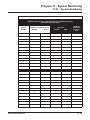
Refer to the following table for the default system passwords. To change the passwords, use Program 90-02.
Password
User Name
Level
Programs at this Level
374772
NEC-I
1 (MF)
All programs
12345678
ASPIRE
2 (IN)
All programs in this section not listed below for SA and SB
0000
ADMIN1
3 (SA)
10-01, 10-02, 10-12, 10-13, 10-14, 10-15, 10-16, 10-17, 10-18,
10-22, 12-02, 12-03, 12-04, 15-01, 15-07, 15-09, 15-10, 15-11,
20-16, 21-07, 21-14, 22-04, 22-11, 25-08, 30-03, 32-02, 40-02,
41-02, 41-03, 41-04, 41-05, 41-06, 41-07, 41-08, 41-09, 41-10,
41-11, 41-12, 41-13, 41-14, 41-15, 41-16, 41-17, 41-18, 90-03,
90-04, 90-06, 90-07, 90-18, 90-19
9999
ADMIN2
4 (SB)
13-04, 13-05, 13-06
How to Exit the Programming Mode
To exit the programming mode:
When you are done programming, you must be out of a program’s options to exit (pressing the MSG key
will exit the program’s option).
1.
Press MSG key to exit the program’s options, if needed.
Program Mode
Base Service OP1 OP2
2.
3.
38 ◆
Press SPK. You see, "Saving System Data" if changes to were to the system’s programming.
The display shows "Complete Data Save" when completed and will exit the phone to an idle
mode.
To save a customer’s database, a blank PC-ATA card is required. Insert the card into
the NTCPU and, using Program 90-03, save the software to the PC-ATA card. (Program
90-04 is used to reload the customer data if necessary.) Note that a PC-ATA card can only
hold one customer database. Each database to be saved will require its own separate card.
Aspire ISDN PRI Manual
Programming
Before You Start Programming
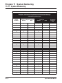
Using Keys to Move Around in the Programs
Once you enter the programming mode, use the keys in the following chart to enter data, edit data and move
around in the menus.
Keys for Entering Data
Use this key...
0-9 and *
When you want to . . .
Enter data into a program.
HOLD
Complete the programming step you just made (like pressing Enter on a PC
keyboard). When a program entry displays, press HOLD to bypass the entry
without changing it.
CONF
Delete the entry to the left (like pressing Backspace on a PC keyboard).
MSG
Exit one step at a time from the program window currently being viewed.
For example, if you’re programming item 5 in 15-03, pressing MSG will
allow you to enter a new option in program 15-03. Pressing MSG again will
allow you to select a new program in the 15- series. Pressing MSG a third
time will allow you to enter a new program beginning with ‘1’. Pressing
MSG one last time will bring you to the beginning program display, allowing you to enter any program number.
FLASH
Switch extension, line, etc. being programmed by pressing FLASH. The
cursor moves up to the top row of the display. Pressing FLASH again moves
the cursor back to the middle row.
LINE KEYS
Use pre-programmed settings to help with the program entry. These settings
vary between programs from LINE 1 = 0 (off) and LINE 2 = 1 (on) to preset
values for timers where LINE 1 = 5, LINE 2 = 10, LINE 3 = 15, etc.
For programs with this option, the line key which currently matches the programmed setting will light steady.
The display may also indicate Soft Keys which will allow you to select the
values as well (-1 and +1 will step through these pre-programmed settings.)
LINE KEY 1
Program a pause into an Abbreviated Dialing bin.
LINE KEY 2
Program a recall/flash into an Abbreviated Dialing bin.
LINE KEY 3
Program a @ into an Abbreviated Dialing bin.
VOL ▲
Scroll backward through a list of entry numbers (e.g., from extension 301 to
302, 303, etc.) or through entries in a table (e.g., Common Permit Table).
If you enter data and then press this key, the system accepts the data before
scrolling forward.
VOL ▼
Scroll forward through a list of entry numbers (e.g., from extension 301 to
302, 303, etc.) or through entries in a table (e.g., Common Permit Table).
If you enter data and then press this key, the system accepts the data before
scrolling backward
Aspire ISDN PRI Manual
◆ 39
Programming
Before You Start Programming
Programming Names and Text Messages
Several programs (e.g., Program 20-16: Selectable Display Messages) require you to enter text. Use the following chart when entering and editing text. When using the keypad digits, press the key once for the first
character, twice for the second character, etc. For example, to enter a C, press key “2” three times. Press the
key six times display the lower case letter. The name can be up to 12 digits long.
With Software Prior to 2.05:
Key for Entering Names
Use this keypad digit . . .
1
Enter characters:
1 @ [ ¥ ] ^ _ ‘ { | } ← →
Press repeatedly to scroll through the list. After selecting your entry, press the
next letter or use the left scroll or right scroll Soft Key to move the cursor.
2
Enter characters A-C, a-c, 2. After selecting your entry, press the next letter or
use the left scroll or right scroll Soft Key to move the cursor.
3
Enter characters D-F, d-f, 3. After selecting your entry, press the next letter or
use the left scroll or right scroll Soft Key to move the cursor.
4
Enter characters G-I, g-i, 4. After selecting your entry, press the next letter or use
the left scroll or right scroll Soft Key to move the cursor.
5
Enter characters J-L, j-l, 5. After selecting your entry, press the next letter or use
the left scroll or right scroll Soft Key to move the cursor.
6
Enter characters M-O, m-o, 6. After selecting your entry, press the next letter or
use the left scroll or right scroll Soft Key to move the cursor.
7
Enter characters P-S, p-s, 7. After selecting your entry, press the next letter or
use the left scroll or right scroll Soft Key to move the cursor.
8
Enter characters T-V, t-v, 8. After selecting your entry, press the next letter or use
the left scroll or right scroll Soft Key to move the cursor.
9
Enter characters W-Z, w-z, 9. After selecting your entry, press the next letter or
use the left scroll or right scroll Soft Key to move the cursor.
0
Enter characters:
0 ! “ # $ % & ‘ ( )
Press repeatedly to scroll through the list. After selecting your entry, press the
next letter or use the left scroll or right scroll Soft Key to move the cursor.
*
Enter characters:
* + , - . / : ; < = > ?
Press repeatedly to scroll through the list. After selecting your entry, press the
next letter or use the left scroll or right scroll Soft Key to move the cursor.
Soft Key Left/Right
Arrows
CONF
CLEAR
40 ◆
When you want to. . .
Accepts an entry (only required if two letters on the same key are needed - ex: TOM)
and moves cursor in the arrows direction.
Clear the character entry one character at a time.
Clear all the entries from the point of the flashing cursor and to the right.
Aspire ISDN PRI Manual
Programming
Before You Start Programming
With Software 2.05+:
Use this keypad
digit . . .
1
2
3
4
5
6
7
8
9
0
*
#
CONF
CLEAR
When you want to. . .
Enter characters:
1 @ [ ¥ ] ^ _ ` { | } → ← Á À Â Ã Ç É Ê ì ó
Enter characters A-C, a-c, 2.
Enter characters D-F, d-f, 3.
Enter characters G-I, g-i, 4.
Enter characters J-L, j-l, 5.
Enter characters M-O, m-o, 6.
Enter characters P-S, p-s, 7.
Enter characters T-V, t-v, 8.
Enter characters W-Z, w-z, 9.
Enter characters:
0 ! “ # $ % & ’ ( ) ô Õ ú ä ö ü α ε θ
Enter characters:
* + , - . / : ; < = > ? π ∑ σ Ω ∞ ¢ £
# = Accepts an entry (only required if two letters on the same key are needed - ex: TOM).
Pressing # again = Space. (In system programming mode, use the right arrow soft key
instead to accept and/or add a space.)
Clear the character entry one character at a time.
Clear all the entries from the point of the flashing cursor and to the right.
When using i-Series telephones on the Aspire system, not all the same characters are available. Refer to the
following chart for the i-Series characters:
Use this keypad
digit . . .
1
2
3
4
5
6
7
8
9
0
*
#
CONF
CLEAR
Aspire ISDN PRI Manual
When you want to. . .
Enter characters:
1 @ [ ¥ ] ^ _ ` { | } → ← å blank blank blank blank blank
blank blank blank
Enter characters A-C, a-c, 2.
Enter characters D-F, d-f, 3.
Enter characters G-I, g-i, 4.
Enter characters J-L, j-l, 5.
Enter characters M-O, m-o, 6.
Enter characters P-S, p-s, 7.
Enter characters T-V, t-v, 8.
Enter characters W-Z, w-z, 9.
Enter characters:
0 ! “ # $ % & ’ ( ) blank blank blank ä ö ü α ε θ
Enter characters:
* + , - . / : ; < = > ? π ∑ σ Ω ∞ ¢ £
# = Accepts an entry (only required if two letters on the same key are needed - ex: TOM).
Pressing # again = Space.
Clear the character entry one character at a time.
Clear all the entries from the point of the flashing cursor and to the right.
◆ 41
Programming
Before You Start Programming
Using Soft Keys For Programming
Each Aspire display telephone provides interactive soft keys for intuitive feature access. The options for
these keys will automatically change depending on where you are in the system programming. Simply press
the Soft Key located below the option you wish and the display will change accordingly.
_
Program Mode
Base Service OP1 OP2
❍ ❍ ❍ ❍
Pressing the VOLUME ▲ or VOLUME ▼ will scroll between the menus.
_
Program Mode
Hard Mtnance
❍ ❍ ❍ ❍
What the Soft Key Display Prompts Mean
When using a display phone in programming mode, you will see various Soft Key options displayed. These
keys will allow you to easily select, scan, or move through the programs.
Soft key Display Prompts
If you press this Soft Key . . .
back
The system will. . .
Go back one step in the program display.
You can press VOLUME ▲ or VOLUME ▼ to scroll
forwards or backwards through a list of Programs.
↑
↓
select
←
→
−1
+1
42 ◆
Scroll down through the available programs.
Scroll up through the available programs.
Select the currently displayed program.
Move the cursor to the left.
Move the cursor to the right.
Move back through the available program options.
Move forward through the available program options.
Aspire ISDN PRI Manual
Program 10 : System Configuration Setup
10-03 : PCB Setup
Program 10 : System Configuration Setup
10-03 : PCB Setup
Level:
Aspire S
IN
•
Available.
Aspire
•
Available.
Description
Use Program 10-03 : PCB Setup to setup and confirm the Basic Configuration data for each PCB.
When changing a defined terminal type, first set the type to ‘0’ and then plug the new device in to
have the system automatically define it or you may have to reseat the PCB.
Note: The items highlighted in gray are read only and cannot be changed.
Input Data
For PRIU Unit
Item
No.
Item
Input Data
Default
01
ISDN Line Mode
0 = Not set
1 = T-Bus
2 = S-Bus
3 = Network Mode (Leased Line)
4 = Network Mode (Interconnected Line)
5 = Network Mode (Interconnected Line, Fixed Layer 1=NT)
6 = S-Point (Leased Line)
1
02
Logical Port Number
(see Note 1)
1 = for T-Bus 1-200
2 = for S-Bus 1-256
0
03
CRC Multi-frame(CRC4)
(Only E1[30B+D] Mode)
0 = off
1 = on
0
04
Layer 3 Timer Type (see Note 2)
1-5
1
05
CLIP Information
Based on this setting, the system will
include a “Presentation Allowed” (1)
or “Presentation Restricted” (0) in the
Setup message to allow or deny the
Calling Party Number. Program
15-01-04 must also be set to a ‘1’ if
this option is enabled.
0 = Disable
1 = Enable
1
06
Length of cable
0 = 0 40m
1 = 40 81m
2 = 81 122m
3 = 122 162m
4 = 162 200m
0
07
S-Point DID Digits
0-4
0
08
Dial Sending Mode
0 = Enblock Sending
1 = Overlap Sending
0
Aspire ISDN PRI Manual
◆ 43
Program 10 : System Configuration Setup
10-03 : PCB Setup
Item
No.
Item
Input Data
Default
09
Dial Information Element
(Only for Overlap Sending Mode)
0 = Keypad Facility
1 = Called Party Number
0
10
Master/Slave System (Network Mode
only)
0 = Slave System
1 = Master System
0
11
Networking System Number (Network Mode only)
0-50
0
12
short / long-haul
0 = short-haul
1 = long-haul
0
13
Loss-Of-Signal detection limit
In short-haul mode
0 = 0.91V
1 = 0.74V
2 = 0.59V
3 = 0.42V
4 = 0.32V
5 = 0.21V
6 = 0.16V
7 = 0.10V
0
In long-haul mode
0 = 1.70V
1 = 0.84V
2 = 0.84V
3 = 0.45V
4 = 0.45V
5 = 0.20V
6 = 0.10V
7 = not defined
14
Service Protocol for S-Point
Note 1.
Note 2.
0 = Keypad Facility
1 = Specified Protocol for Aspire System
0
The start port number of a PRI line is displayed. Thirty logic ports are automatically
assigned to a PRI line.
Each timer value of Layer3 is set up for each type in Program 81-06 (T-Bus) and Program 82-06 (S-Bus).
Conditions
(A.) When changing a defined terminal type, first set the type to ‘0’ and then plug the new device in
to have the system automatically define it or redefine the type manually.
(B.) The system must have a PCB installed in order to view/change the options for that type of
PCB.
Feature Cross Reference
None
44 ◆
Aspire ISDN PRI Manual
Program 10 : System Configuration Setup
10-03 : PCB Setup
Telephone Programming Instructions
To enter data for Program 10-03 (PCB Setup):
1.
2.
Enter the programming mode.
10 03
10-02-01
Slot No 1
ESIport01 CH1 1 :TEL |1
↓ select
back ↑
3.
Enter the number of the item you want to program.
10-02-nn
nnnnn
back ↑
4.
5.
6.
Aspire ISDN PRI Manual
Slot No 1
↓
select
Select a slot number to be programmed by pressing the VOLUME ▲ or VOLUME ▼ keys.
Or, press FLASH once to select the slot number or press FLASH twice to select a port number. Enter the slot or port number.
Enter data for the item you selected + HOLD.
Enter data for the next item in the program.
OR
Press MSG once to enter a new item number.
OR
Press MSG until you’ve exited that series’s programming section.
◆ 45
Program 10 : System Configuration Setup
10-08 : Pre-Ringing Setup
10-08 : Pre-Ringing Setup
Level:
IN
Aspire S
•
Available.
Aspire
•
Available.
Description
Use Program 10-08 : Pre-Ringing Setup to enable or disable pre-ringing for trunk calls. This sets
how a trunk initially rings a telephone. With pre-ringing, a burst of ringing occurs as soon as the
trunk’s LED flashes. The call then continues ringing with the normal ring cadence cycle. Without
pre-ringing, the call starts ringing only when the normal ring cadence cycle occurs. This may cause
a ring delay, depending on when call detection occurs in reference to the ring cycle.
Input Data
Input Data
Default
0 = disable
1 = enable
Prior to 2.13 Software:
1
With 2.13+ Software:
0
Conditions
None
Feature Cross Reference
●
46 ◆
Central Office Calls, Answering
Aspire ISDN PRI Manual
Program 10 : System Configuration Setup
10-08 : Pre-Ringing Setup
Telephone Programming Instructions
To enter data for Program 10-08 (Pre-Ringing Setup):
1.
2.
Enter the programming mode.
10 08
10-08-01
Pre-ringing
back ↑
3.
1:Yes
select
↓
Enter the number of the item you want to program.
10-08-nn
nnnnn
←
4.
5.
Aspire ISDN PRI Manual
−1
+1
→
Enter data for the item you selected + HOLD.
Enter data for the next item in the program.
OR
Press MSG once to enter a new item number.
OR
Press MSG until you’ve exited that series’s programming section.
◆ 47
Program 10 : System Configuration Setup
10-08 : Pre-Ringing Setup
- For Your Notes -
48 ◆
Aspire ISDN PRI Manual
Program 11 : System Numbering
11-01 : System Numbering
Program 11 : System Numbering
11-01 : System Numbering
Level:
IN
Aspire S
•
Available.
Aspire
•
Available.
Description
Use Program 11-01 : System Numbering to set the system’s internal (Intercom) numbering plan.
The numbering plan assigns the first and second digits dialed and affects the digits an extension
user must dial to access other extensions and features, such as service codes and trunk codes. If the
default numbering plan does not meet the site requirements, use this program to tailor the system
numbering to the site.
CAUTION
Improperly programming this option can adversely affect system operation. Make
sure you thoroughly understand the default numbering plan before proceeding. If you
must change the standard numbering, use the chart for System Numbering (page 51)
to keep careful and accurate records of your changes.
Before changing your numbering plan, use the PC Program or Web PC Program to
make a backup copy of your system’s data.
Changing the numbering plan consists of three steps:
1. Enter the digits you want to change.
2. Specify the length of the code you select to change.
3. Assign a function to the code selected.
Step 1: Enter the digit(s) you want to change
You can make either single or two digit entries. In the Dialed Number column in the System
Numbering (page 51) table, the nX rows (e.g., 1X) are for single digit codes. The remaining
rows (e.g., 11, 12, etc.) are for two digit codes.
● Entering a single digit affects all the Dialed Number entries beginning with that digit. For
example, entering 6 affects all number plan entries beginning with 6. The entries you make
in step 2 and step 3 below affect the entire range of numbers beginning with 6. (For
example, if you enter 3 in step 2 the entries affected would be 600-699. If you enter 4 in
step 2 below, the entries affected would be 6000-6999.)
● Entering two digits lets you define codes based on the first two digits a user dials. For
example, entering 60 allows you to define the function of all codes beginning with 60. In
the default program, only * and # use two-digit codes. All the other codes are single digit.
If you enter a two digit code between 0 and 9, be sure to make separate entries for all the
other two digit codes within the range as well. This is because in the default program all
the two digit codes between 0 and 9 are undefined.
Aspire ISDN PRI Manual
◆ 49
Program 11 : System Numbering
11-01 : System Numbering
Description (Cont’d)
Step 2: Specify the length of the code you want to change
After you specify a single or two digit code, you must tell the system how many digits comprise the code. This is the Number of Digits Required column in the System Numbering
(page 51) table. In the default program, all codes from 100-999 are three digits long. Codes
beginning with 0 are one digit long. Codes beginning with * are 3 digits long and codes beginning with # are 4 digits long.
Step 3: Assign a function to the code selected
After entering a code and specifying its length, you must assign its function. This is the Dial
Type column in the System Numbering (page 51) table. The choices are:
Dial Types
Dial Type Description
Related Program
0
- Not Used -
1
Service Code
11-10 : Service Code Setup (for System Administrator)
11-11 : Service Code Setup (for Registration)
11-12 : Service Code Setup (for Service Access)
11-13 : Service Code Setup (for ACD)
11-14 : Service Code Setup (for HOTEL)
11-15 : Service Code Setup (Special access)
2
Extension Number
11-02 : Extension Numbers
11-04 : Virtual Extension Numbers
11-06 : 2PGDAD (ACI) Extension Numbers
11-07 : Department Calling Group Numbers
11-08 : 2PGDAD (ACI) Group Pilot Numbers
3
Trunk Access Code
11-09 : Trunk Access Code
4
Special Trunk Access
11-09 : Trunk Access Code
5
Operator Access
20-17 : Operator’s Extension
6
ARS/F-Route Access
44-xx
8
Networking
10-03 : PCB Setup
10-12 : NTCPU Network Setup
10-20 : LAN Setup for External Equipment
10-27 : IP System IP
●
Changing the Dial Type for a range of codes can have a dramatic affect on how your system operates. Assume, for example, the site is a hotel that has room numbers from 100399. In order to make extension numbers correspond to room numbers, you should:
- In Program 11-02, reassign extension numbers on each floor from 100 to 399.
(Other applications might also require you to change entries in Program 11-10 through
11-16.)
Default
See the following tables.
50 ◆
Aspire ISDN PRI Manual
Program 11 : System Numbering
11-01 : System Numbering
System Numbering
Dial Types: 1=Service Code, 2=Extension Number, 3=Trunk Access,
4=Special Trunk Access, 5=Operator Access, 6=Flexible Routing,
8=Networking, 0=Not Used
Dialed
Number
Number of Digits Required
Default
New
Dial Type
Default
New
Network
System ID
[if type 8] 0-50
1X
3
1
11
0
0
12
0
0
13
0
0
14
0
0
15
0
0
16
0
0
17
0
0
18
0
0
19
0
0
10
0
0
1*
0
0
1#
0
0
2X
3
2
21
0
0
22
0
0
23
0
0
24
0
0
25
0
0
26
0
0
27
0
0
28
0
0
29
0
0
20
0
0
2*
0
0
2#
0
0
Aspire ISDN PRI Manual
◆ 51
Program 11 : System Numbering
11-01 : System Numbering
System Numbering
Dial Types: 1=Service Code, 2=Extension Number, 3=Trunk Access,
4=Special Trunk Access, 5=Operator Access, 6=Flexible Routing,
8=Networking, 0=Not Used
Dialed
Number
Number of Digits Required
Default
New
Dial Type
Default
New
Network
System ID
[if type 8] 0-50
52 ◆
3X
3
2
31
0
0
32
0
0
33
0
0
34
0
0
35
0
0
36
0
0
37
0
0
38
0
0
39
0
0
30
0
0
3*
0
0
3#
0
0
4X
3
2
41
0
0
42
0
0
43
0
0
44
0
0
45
0
0
46
0
0
47
0
0
48
0
0
49
0
0
40
0
0
4*
0
0
4#
0
0
Aspire ISDN PRI Manual
Program 11 : System Numbering
11-01 : System Numbering
System Numbering
Dial Types: 1=Service Code, 2=Extension Number, 3=Trunk Access,
4=Special Trunk Access, 5=Operator Access, 6=Flexible Routing,
8=Networking, 0=Not Used
Dialed
Number
Number of Digits Required
Default
New
Dial Type
Default
New
Network
System ID
[if type 8] 0-50
5X
3
2
51
0
0
52
0
0
53
0
0
54
0
0
55
0
0
56
0
0
57
0
0
58
0
0
59
0
0
50
0
0
5*
0
0
5#
0
0
6X
3
2
61
0
0
62
0
0
63
0
0
64
0
0
65
0
0
66
0
0
67
0
0
68
0
0
69
0
0
60
0
0
6*
0
0
6#
0
0
Aspire ISDN PRI Manual
◆ 53
Program 11 : System Numbering
11-01 : System Numbering
System Numbering
Dial Types: 1=Service Code, 2=Extension Number, 3=Trunk Access,
4=Special Trunk Access, 5=Operator Access, 6=Flexible Routing,
8=Networking, 0=Not Used
Dialed
Number
Number of Digits Required
Default
New
Dial Type
Default
New
Network
System ID
[if type 8] 0-50
54 ◆
7X
3
2
71
0
0
72
0
0
73
0
0
74
0
0
75
0
0
76
0
0
77
0
0
78
0
0
79
0
0
70
0
0
7*
0
0
7#
0
0
8X
3
1
81
0
0
82
0
0
83
0
0
84
0
0
85
0
0
86
0
0
87
0
0
88
0
0
89
0
0
80
0
0
8*
0
0
8#
0
0
Aspire ISDN PRI Manual
Program 11 : System Numbering
11-01 : System Numbering
System Numbering
Dial Types: 1=Service Code, 2=Extension Number, 3=Trunk Access,
4=Special Trunk Access, 5=Operator Access, 6=Flexible Routing,
8=Networking, 0=Not Used
Dialed
Number
Number of Digits Required
Default
New
Dial Type
Default
New
Network
System ID
[if type 8] 0-50
9X
1
3
91
0
0
92
0
0
93
0
0
94
0
0
95
0
0
96
0
0
97
0
0
98
0
0
99
0
0
90
0
0
9*
0
0
9#
0
0
0X
1
5
01
0
0
02
0
0
03
0
0
04
0
0
05
0
0
06
0
0
07
0
0
08
0
0
09
0
0
00
0
0
0*
0
0
0#
0
0
Aspire ISDN PRI Manual
◆ 55
Program 11 : System Numbering
11-01 : System Numbering
System Numbering
Dial Types: 1=Service Code, 2=Extension Number, 3=Trunk Access,
4=Special Trunk Access, 5=Operator Access, 6=Flexible Routing,
8=Networking, 0=Not Used
Dialed
Number
Number of Digits Required
Default
New
Dial Type
Default
New
Network
System ID
[if type 8] 0-50
56 ◆
*X
2
1
*1
0
0
*2
0
0
*3
0
0
*4
0
0
*5
0
0
*6
0
0
*7
0
0
*8
0
0
*9
0
0
*0
0
0
**
0
0
*#
0
0
#X
0
0
#1
2
1
#2
2
1
#3
2
1
#4
2
1
#5
2
1
#6
2
1
#7
2
1
#8
2
1
#9
2
1
#0
2
1
#*
4
1
##
2
1
Aspire ISDN PRI Manual
Program 11 : System Numbering
11-01 : System Numbering
Conditions
None
Feature Cross Reference
●
Flexible System Numbering
Telephone Programming Instructions
To enter data for Program 11-01 (System Numbering):
1.
2.
Enter the programming mode.
11 01
11-01-01 Dial 1
1x
Digit 3
↓
back ↑
3.
select
Enter the number of the item you want to program.
11-01-nn
nnnnn
←
→
4.
Select the dial number to be programmed by pressing the FLASH or the VOLUME
VOLUME ▼ keys.
5.
Enter data for the item you selected + HOLD.
6.
Enter data for the next item in the program.
OR
Press MSG once to enter a new item number.
OR
Press MSG until you’ve exited that series’s programming section.
Aspire ISDN PRI Manual
▲ or
◆ 57
Program 11 : System Numbering
11-09 : Trunk Access Code
11-09 : Trunk Access Code
Level:
Aspire S
IN
•
Aspire
Available.
•
Available.
Description
Use Program 11-09 : Trunk Access Code to assign the trunk access code (normally 9). The trunk
access code can be set from 1 to 8 digits which is defined to type 3 and 4 in Program 11-01. This is
the code extension users dial to access Automatic Route Selection. The Individual Trunk Access
Code is used when Trunk Group Routing is desired for an outgoing line.
Caution
The digit 9 is defined in Program 11-01 as Dial Type 3 with the Number of Digits
Required set to 1. If you change the trunk access code in Program 11-09, you must
make the corresponding changes in Program 11-01.
Input Data
Item
No.
Item
Input Data
Default
Description
01
Trunk
Access
Code
Dial
(Up to 4 digits)
9
Use this program to
assign the trunk access
code (normally 9). This
is the code extension
users dial to access Automatic Route Selection.
•
•
•
•
11-01 : System Numbering
14-01 : Trunk Basic Data Setup
14-05 : Trunk Group
14-06 : Trunk Group Routing
02
Alternate
Trunk
Route
Access
Code
Dial
(Up to 4 digits)
No setting
Use this program to
define additional trunk
access codes.
When a user dials the
Alternate Trunk Route
Access Code, the system
routes their call to the
Alternate Trunk Route.
•
•
•
•
•
11-01 : System Numbering
14-01 : Trunk Basic Data Setup
14-05 : Trunk Group
14-06 : Trunk Group Routing
21-02 : Trunk Group Routing for
Extensions
21-15 : Alternate Trunk Group
Routing for Extensions
Related Program
•
Conditions
None
Feature Cross Reference
●
●
●
58 ◆
Automatic Route Selection
Central Office Calls, Placing
Trunk Group Routing
Aspire ISDN PRI Manual
Program 11 : System Numbering
11-09 : Trunk Access Code
Telephone Programming Instructions
To enter data for Program 11-09 (Trunk Access Code):
1.
2.
Enter the programming mode.
11 09
11-09-01
Trunk_Access_Code0
↓ select
back ↑
3.
Enter the number of the item you want to program.
11-09-nn
nnnnn
←
4.
5.
Aspire ISDN PRI Manual
→
Enter data for the item you selected + HOLD.
Enter data for the next item in the program.
OR
Press MSG once to enter a new item number.
OR
Press MSG until you’ve exited that series’s programming section.
◆ 59
Program 11 : System Numbering
11-09 : Trunk Access Code
- For Your Notes -
60 ◆
Aspire ISDN PRI Manual
Program 14 : Trunk, Basic Setup
14-01 : Basic Trunk Data Setup
Program 14 : Trunk, Basic Setup
14-01 : Basic Trunk Data Setup
Level:
IN
Aspire S
•
Aspire
Available.
•
Available.
Description
Use Program 14-01 : Basic Trunk Data Setup to set the basic options for each trunk port. Refer
to the chart below for a description of each option, its range and default setting.
Input Data
Trunk port number
1-200
Item
No.
Item
01
Trunk Name
Set the names for trunks. The trunk name
displays at display keysets for incoming
and outgoing calls.
Up to 12 characters
02
Transmit CODEC Gain Type
Use this option to select the CODEC gain
for the trunk. The option sets the amount
of gain (signal amplification) for the trunk
you are programming.
1~63
(-15.5 ~ +15.5dB in
.5dB intervals)
32 (0dB)
03
Receive CODEC Gain Type
Use this option to select the CODEC gain
for the trunk. The option sets the amount
of gain (signal amplification) for the trunk
you are programming.
1~63
(-15.5 ~ +15.5dB in
.5dB intervals)
32 (0dB)
07
Outgoing Calls
Use this option to allow/prevent outgoing
calls on the trunk you are programming.
0 = prevented
1 = allowed
1
10
DTMF Tones for Outgoing Calls
Use this option to enable (1) or disable (0)
DTMF tones for outgoing trunk calls.
0 = disable
1 = enable
0
Aspire ISDN PRI Manual
Input Data
Default
Related
Program
1 = Line 001
|
Line 200 = Line 200
◆ 61
Program 14 : Trunk, Basic Setup
14-01 : Basic Trunk Data Setup
Default
Trunk Port Number
Name
001
LINE 001
002
LINE 002
:
:
200
LINE 200
Conditions
None
Feature Cross Reference
Refer to features in above chart.
Telephone Programming Instructions
To enter data for Program 14-01 (Basic Trunk Data Setup):
1.
2.
Enter the programming mode.
14 01
14-01-01
Trunk1
TRK Name = LINE 001
↓ select
back ↑
3.
Enter the number of the item you want to program.
14-01-nn
nnnnn
←
62 ◆
Trunknnn
→
4.
Select the trunk number to be programmed by pressing the FLASH or the VOLUME
VOLUME ▼ keys.
5.
6.
Enter data for the item you selected + HOLD.
Enter data for the next item in the program.
OR
Press MSG once to enter a new item number.
OR
Press MSG until you’ve exited that series’s programming section.
▲ or
Aspire ISDN PRI Manual
Program 14 : Trunk, Basic Setup
14-05 : Trunk Group
14-05 : Trunk Group
Level:
IN
Aspire S
•
Aspire
Available.
•
Available.
Description
Use Program 14-05 : Trunk Groups to assign trunks to Trunk Groups. You can also assign the
outbound priority for trunks within the group. When users dial up the trunk group, they seize the
trunks in the order you specify in the outbound priority entry.
Input Data
Trunk Port Number
001-200
Trunk Group Number
Order Number
0-100
1-200
Default
Trunk Port
Group
Priority
1
1
1
:
:
:
200
1
200
Conditions
None
Feature Cross Reference
●
Aspire ISDN PRI Manual
Trunk Groups
◆ 63
Program 14 : Trunk, Basic Setup
14-05 : Trunk Group
Telephone Programming Instructions
To enter data for Program 14-05 (Trunk Group):
1.
2.
Enter the programming mode.
14 05
14-05-01 Trunk1
Group No.
1
↓ select
back ↑
3.
Enter the number of the item you want to program.
14-05-nn
nnnnn
←
64 ◆
Trunknnn
→
4.
Select the trunk number to be programmed by pressing the FLASH or the VOLUME
VOLUME ▼ keys.
5.
6.
Enter data for the item you selected + HOLD.
Enter data for the next item in the program.
OR
Press MSG once to enter a new item number.
OR
Press MSG until you’ve exited that series’s programming section.
▲ or
Aspire ISDN PRI Manual
Program 14 : Trunk, Basic Setup
14-07 : Trunk Access Map Setup
14-07 : Trunk Access Map Setup
Level:
IN
Aspire S
•
Available.
Aspire
•
Available.
Description
Use Program 14-07 : Trunk Access Map Setup to set up the Trunk Access Maps. This sets an
extension’s access options for trunks. For example, an extension can only place outgoing calls on
trunks to which it has outgoing access. There are 200 Access Maps with all 200 trunk ports programmed in Map 1 with full access.
An extension can use one of the maps you set up in this program. Use Program 15-06 to assign
Trunk Access Maps to extensions. Each trunk can have one of eight access options for each Access
Map.
Input Data
Access Map Number
Trunk Port Number
001-200
1-200
Input Data
0 = No access
1 = Outgoing access only
2 = Incoming access only
3 = Access only when trunk on Hold
4 = Outgoing access and access when trunk on Hold
5 = Incoming access and access when trunk on Hold
6 = Incoming and Outgoing access
7 = Incoming access, outgoing access and access when trunk on Hold
Default
●
●
Access Map 1 = Trunk Ports 1-200 assigned with option ‘7’ access (incoming and outgoing
access and access when trunk is on Hold).
Access Maps 2-200 - Trunk Ports 1-200 assigned with option ‘0’ access (no access).
Conditions
None
Feature Cross Reference
●
●
Aspire ISDN PRI Manual
Central Office Calls, Answering
Central Office Calls, Placing
◆ 65
Program 14 : Trunk, Basic Setup
14-07 : Trunk Access Map Setup
Telephone Programming Instructions
To enter data for Program 14-07 (Trunk Access Map Setup):
1.
2.
Enter the programming mode.
14 07
14-07-01 Access Map1
TRK_ 001=7:OTG/INC/Hold
↓ select
back ↑
3.
Enter the number of the item you want to program.
14-07-nn
nnnnn
←
66 ◆
Access Mapnnn
→
4.
Select the Access Map number to be programmed by pressing the FLASH or the VOLUME
▲ or VOLUME ▼ keys.
5.
6.
Enter data for the item you selected + HOLD.
Enter data for the next item in the program.
OR
Press MSG once to enter a new item number.
OR
Press MSG until you’ve exited that series’s programming section.
Aspire ISDN PRI Manual
Program 15 : Extension, Basic Setup
15-01 : Basic Extension Data Setup
Program 15 : Extension, Basic Setup
15-01 : Basic Extension Data Setup
Level:
SA
Aspire S
•
Aspire
Available.
•
Available.
Description
Use Program 15-01 : Basic Extension Data Setup to define the basic settings for each extension.
Input Data
Extension Number
Item
No.
04
Max. 8 digits
Item
ISDN Caller ID
If both Program 15-01-04 and
10-03-05 are enabled, the system
includes Caller ID in the Setup message as “Presentation Allowed”. If
these options are disabled, it will be
“Presentation Restricted”.
Input Data
0 = Disable
1 = Enable
Default
Related
Program
1
10-03-05
Conditions
None
Feature Cross Reference
Refer to chart above.
Aspire ISDN PRI Manual
◆ 67
Program 15 : Extension, Basic Setup
15-01 : Basic Extension Data Setup
Telephone Programming Instructions
To enter data for Program 15-01 (Basic Extension Data Setup):
1.
2.
Enter the programming mode.
15 01
15-01-01 TEL301
Ext.Name = EXT 301
↓ select
back ↑
3.
Enter the number of the item you want to program.
15-01-nn
nnnnn
←
68 ◆
TELnnn
→
4.
Select the telephone number to be programmed by pressing the FLASH or the VOLUME
or VOLUME ▼ keys.
5.
6.
Enter data for the item you selected + HOLD.
Enter data for the next item in the program.
OR
Press MSG once to enter a new item number.
OR
Press MSG until you’ve exited that series’s programming section.
▲
Aspire ISDN PRI Manual
Program 15 : Extension, Basic Setup
15-02 : Multi-Line Telephone Basic Data Setup
15-02 : Multi-Line Telephone Basic Data Setup
Level:
Aspire S
IN
Aspire
•
Available.
•
Available.
•
Item 24 available.
•
Item 24 available with software 1.11+.
•
Item 26 available.
•
Item 26 available with software 1.11+.
Description
Use Program 15-02 : Multi-Line Telephone Basic Data Setup to set up various keyset options.
Input Data
Extension Number
Item
No.
02
Item
Trunk Ring Tone
Use this option to set the tone (pitch)
of the incoming trunk ring for the
extension port you are programming.
Aspire ISDN PRI Manual
Max. 8 digits
Input Data
1 = High
2 = Mid range
3 = Low
4 = Ring Tone 1
5 = Ring Tone 2
6 = Ring Tone 3
7 = Ring Tone 4
8 = Ring Tone 5
Default
Related
Program
2
22-03
◆ 69
Program 15 : Extension, Basic Setup
15-02 : Multi-Line Telephone Basic Data Setup
Incoming Signal Frequency Pattern
Type
Frequency 1
Frequency 2
Modulation
External Incoming Signal Frequency (Pattern 1)
High
Middle
Low
1100
660
520
1400
760
660
16Hz
16Hz
16Hz
External Incoming Signal Frequency (Pattern 2)
High
Middle
Low
1100
660
520
1400
760
660
8Hz
8Hz
8Hz
External Incoming Signal Frequency (Pattern 3)
High
Middle
Low
1100
660
520
1100
660
520
Envelope
Envelope
Envelope
External Incoming Signal Frequency (Pattern 4)
High
Middle
Low
1100
660
520
1100
660
520
No modulation
No modulation
No modulation
Internal Incoming Signal Frequency
High
Middle
Low
1100
660
520
1400
760
660
8Hz
8Hz
8Hz
Conditions
None
Feature Cross Reference
Refer to above chart.
Telephone Programming Instructions
To enter data for Program 15-02 (Multi-Line Telephone Basic Data Setup):
1.
2.
Enter the programming mode.
15 02
15-02-01 TEL301
Language
1:English
↓ select
back ↑
3.
Enter the number of the item you want to program.
15-02-nn
nnnnn
←
70 ◆
TELnnn
→
4.
Select the telephone number to be programmed by pressing the FLASH or the VOLUME
or VOLUME ▼ keys.
5.
6.
Enter data for the item you selected + HOLD.
Enter data for the next item in the program.
OR
Press MSG once to enter a new item number.
OR
Press MSG until you’ve exited that series’s programming section.
▲
Aspire ISDN PRI Manual
Program 15 : Extension, Basic Setup
15-06 : Trunk Access Map for Extensions
15-06 : Trunk Access Map for Extensions
Level:
IN
Aspire S
•
Aspire
Available.
•
Available.
Description
Use Program 15-06 : Trunk Access Map for Extensions to define the trunk access map for each
extension. An extension can only place outgoing calls on trunks to which it has outgoing access.
Use Program 14-07 to define the available 200 access maps.
Input Data
Extension Number
Max. 8 digits
Day/Night Mode
1-8
Day/Night Mode
Trunk Access Map No.
Default
Related Program
1-8
1-200
1
14-07
Conditions
None
Feature Cross Reference
●
●
Aspire ISDN PRI Manual
Central Office Calls, Answering
Central Office Calls, Placing
◆ 71
Program 15 : Extension, Basic Setup
15-06 : Trunk Access Map for Extensions
Telephone Programming Instructions
To enter data for Program 15-06 (Trunk Access Map for Extensions):
1.
2.
Enter the programming mode.
15 06
15-06-01 TEL301
Mode1
Acc-Map 1
↓ select
back ↑
3.
Enter the number of the item you want to program.
15-06-nn
nnnnn
←
72 ◆
TELnnn
→
4.
Select the telephone number to be programmed by pressing the FLASH or the VOLUME
or VOLUME ▼ keys.
5.
6.
Enter data for the item you selected + HOLD.
Enter data for the next item in the program.
OR
Press MSG once to enter a new item number.
OR
Press MSG until you’ve exited that series’s programming section.
▲
Aspire ISDN PRI Manual
Program 15 : Extension, Basic Setup
15-07 : Programmable Function Keys
15-07 : Programmable Function Keys
Level:
Aspire S
SA
•
Aspire
Available.
•
Available.
Description
Use Program 15-07 : Programmable Function Keys to set the functions of an extension’s Programmable Function Key.
For certain functions, you can append data to the key’s basic function. For example, the function 26
appended by data 1 makes a Group Call Pickup key for Pickup Group 1. You can also program
Function Keys using Service Codes.
In order to clear any previously programmed key, press the CLEAR key to erase any displayed
code.
Input Data
Extension Number
Line Key
Number
1-48
Max. 8 digits
Function Number
Additional data
0-99 (General Function Level) (Service Code 851 by default)
* 00-* 99 (Appearance Function Level) (Service Code 852 by default)
Refer to the function number
list.
Default
Programmable keys 1-12 are line keys (key 1 = line 1, key 2 = line 2, etc.). All other programmable
keys are undefined.
Function Number List
[1] General Function Level (00 – 99) (Service Code 851)
Function
Number
Function
00
Not Defined
63
Outgoing Call Without Caller
ID (ISDN)
Aspire ISDN PRI Manual
Additional Data
LED Indication
Red On: Active
◆ 73
Program 15 : Extension, Basic Setup
15-07 : Programmable Function Keys
[2] Appearance Function Level (*00 - *99) (Service Code 852)
Function
Number
Function
Additional Data
*00
Not Used
*01
Trunk Key
Trunk Number (001-200)
*02
Trunk Group/Loop Key
Trunk Group Number (001-100)
*05
Loop Keys
•
•
•
LED Indication
0=Incoming + Trunk Group
Number (001-100)
1=Outgoing + Trunk Group
Number (001-100)
2=Both + Trunk Group
Number (001-100)
Conditions
When a key is programmed using service code 852, that key cannot be programmed with a function
using the 851 code until the key is undefined (000). For example with a Park Key programmed by
dialing 852 + *04 must be undefined by dialing 852 + 000 before it can be programmed as a Voice
Over key by dialing 851 + 48.
Feature Cross Reference
Refer to chart above.
Telephone Programming Instructions
To enter data for Program 15-07 (Programmable Function Keys):
1.
2.
Enter the programming mode.
15 07
15-07-01 TEL301
KY01 = *01
↓ select
back ↑
3.
Enter the number of the item you want to program.
15-07-nn
nnnnn
←
74 ◆
TELnnn
→
4.
Select the telephone number to be programmed by pressing the FLASH or the VOLUME
or VOLUME ▼ keys.
5.
6.
Enter data for the item you selected + HOLD.
Enter data for the next item in the program.
OR
Press MSG once to enter a new item number.
OR
Press MSG until you’ve exited that series’s programming section.
▲
Aspire ISDN PRI Manual
Program 20 : System Option Setup
20-02 : System Options for Multi-Line Telephones
Program 20 : System Option Setup
20-02 : System Options for Multi-Line Telephones
Level:
Aspire S
IN
•
Available.
Aspire
•
Available.
Description
Use Program 20-02 : System Options for Multi-Line Telephones to set various system options
for Multi-Line Telephones.
Input Data
Item
No.
Item
Input Data
Default
02
Trunk Loop Access Key Operating
Mode
Use this option to set the operating mode
of the extension’s trunk group keys. The
keys can be for incoming access, outgoing access or both.
0 = Outgoing / Incoming
1 = Outgoing
2 = Incoming
0
06
Preselection Time
When a keyset user preselects a line key,
the system remembers the preselection
for this interval.
0-64800 seconds
5
Conditions
None
Feature Cross Reference
None
Aspire ISDN PRI Manual
◆ 75
Program 20 : System Option Setup
20-02 : System Options for Multi-Line Telephones
Telephone Programming Instructions
To enter data for Program 20-02 (System Options for Multi-Line Telephones):
1.
2.
Enter the programming mode.
20 02
20-02-01
TRK-GP_Key_OP 0:Display
↓ select
back ↑
3.
Enter the number of the item you want to program.
20-02-nn
nnnnn
←
4.
5.
76 ◆
→
Enter data for the item you selected + HOLD.
Enter data for the next item in the program.
OR
Press MSG once to enter a new item number.
OR
Press MSG until you’ve exited that series’s programming section.
Aspire ISDN PRI Manual
Program 20 : System Option Setup
20-06 : Class of Service for Extensions
20-06 : Class of Service for Extensions
Level:
IN
Aspire S
•
Available.
Aspire
•
Available.
Description
Use Program 20-06 : Class of Service for Extensions to assign a Class of Service to an extension.
There are15 Classes of Service that can be assigned. To specify the options in each Class of Service, refer to Programs 20-07 through 20-13. You make eight entries for Program 20-06, one for
each Night Service Mode.
Input Data
Extension Number
Max. 8 digits
Day/Night Mode
Class of Service for Extensions
1-8
1-15
Default
●
●
Extension number 301 is set as Class 15.
All other extension numbers are set as Class 1.
Conditions
None
Feature Cross Reference
●
Aspire ISDN PRI Manual
Class of Service
◆ 77
Program 20 : System Option Setup
20-06 : Class of Service for Extensions
Telephone Programming Instructions
To enter data for Program 20-06 (Class of Service for Extensions):
1.
2.
Enter the programming mode.
20 06
20-06-01
TEL301
Mode1 Class_No.1
←
3.
Enter the number of the item you want to program.
20-06-nn
nnnnn
←
78 ◆
→
TELnnn
→
4.
Select the telephone number to be programmed by pressing the FLASH or the VOLUME
or VOLUME ▼ keys.
5.
6.
Enter data for the item you selected + HOLD.
Enter data for the next item in the program.
OR
Press MSG once to enter a new item number.
OR
Press MSG until you’ve exited that series’s programming section.
▲
Aspire ISDN PRI Manual
Program 20 : System Option Setup
20-08 : Class of Service Options (Outgoing Call Service)
20-08 : Class of Service Options (Outgoing Call Service)
Level:
IN
Aspire S
Aspire
•
Available.
•
Available.
•
Item 17 available.
•
Item 17 available with software 1.11+.
Description
Use Program 20-08 : Class of Service Options (Outgoing Call Service) to define the outgoing
call feature availability for each extension’s Class of Service.
Input Data
Class of Service Number
01-15
Default
Item
No.
Item
Input
Data
COS
01-14
COS 15
02
Trunk Calls
Turn off or on outgoing trunk calling for the extension.
0 = Off
1 = On
1
1
07
Repeat Redial
Turn off or on an extension’s ability to use Repeat Redial.
0 = Off
1 = On
1
1
12
Department Group Step Calling
Turn off or on an extension’s ability to use Department
Group Step Calling
0 = Off
1 = On
1
1
13
ISDN CLIP
Determine if the ISDN calling line identity presentation
and screening indicators are to be allowed.
0 = Off
1 = On
0
0
14
Call Address Information
0 = Off
1 = On
0
0
15
Block Outgoing Caller ID
Turn off or on the system’s ability to automatically block
outgoing Caller ID information when a user places a call.
If this option is on, the system automatically inserts the
Caller ID block code *67 (defined in Program 14-01-21)
before the user’s dialed digits.
0 = Off
1 = On
0
0
Related
Program
14-01-20
14-01-21
Conditions
None
Feature Cross Reference
●
Aspire ISDN PRI Manual
Class of Service
◆ 79
Program 20 : System Option Setup
20-08 : Class of Service Options (Outgoing Call Service)
Telephone Programming Instructions
To enter data for Program 20-08 (Class of Service Options (Outgoing Call Service)):
1.
2.
Enter the programming mode.
20 08
20-08-01 FCTN Cls1
Intercom_Call
1:On
←
3.
→
Enter the number of the item you want to program.
20-08-nn FCTN Clsnn
nnnnn
←
80 ◆
→
4.
Select the Class of Service number to be programmed by pressing the FLASH or the VOLUME ▲ or VOLUME ▼ keys.
5.
6.
Enter data for the item you selected + HOLD.
Enter data for the next item in the program.
OR
Press MSG once to enter a new item number.
OR
Press MSG until you’ve exited that series’s programming section.
Aspire ISDN PRI Manual
Program 20 : System Option Setup
20-09 : Class of Service Options (Incoming Call Service)
20-09 : Class of Service Options (Incoming Call Service)
Level:
IN
Aspire S
•
Available.
Aspire
•
Available.
Description
Use Program 20-09 : Class of Service Options (Incoming Call Service) to define the incoming
call feature availability for each extension’s Class of Service.
Input Data
Class of Service Number
01-15
Default
Item
No.
03
Item
Sub Address Identification
Define whether an extension displays the Caller
Sub-Address.
Input
data
0 = Off
1 = On
COS
01-14
COS 15
0
0
Related
Program
Conditions
None
Feature Cross Reference
●
Aspire ISDN PRI Manual
Class of Service
◆ 81
Program 20 : System Option Setup
20-09 : Class of Service Options (Incoming Call Service)
Telephone Programming Instructions
To enter data for Program 20-09 (Class of Service Options (Incoming Call Service)):
1.
2.
Enter the programming mode.
20 09
20-09-01 FCTN Cls1
2nd_Call_DDI-Ovrride0:Of
↓ select
back ↑
3.
Enter the number of the item you want to program.
20-09-nn FCTN Clsnn
nnnnn
←
82 ◆
→
4.
Select the Class of Service number to be programmed by pressing the FLASH or the VOLUME ▲ or VOLUME ▼ keys.
5.
6.
Enter data for the item you selected + HOLD.
Enter data for the next item in the program.
OR
Press MSG once to enter a new item number.
OR
Press MSG until you’ve exited that series’s programming section.
Aspire ISDN PRI Manual
Program 20 : System Option Setup
20-13 : Class of Service Options (Supplementary Service)
20-13 : Class of Service Options (Supplementary Service)
Level:
IN
Aspire S
Aspire
•
Available.
•
Available.
•
Item 38 available.
•
Item 38 available with software 1.20+.
Description
Use Program 20-13 : Class of Service Options (Supplementary Service) to define the supplementary feature availability for each extension’s Class of Service.
Input Data
Class of Service Number
01-15
Default
Item
No.
Item
Input Data
COS 01-14
COS 15
23
Display the Reason for Transfer
Select whether an extension should display the reason a call is
being transferred to their extension (Call Forward Busy, Call Forward No Answer, DND).
0 = Off
1 = On
0
0
31
Connected Line Identification (COLP)
0 = Off
1 = On
0
0
Conditions
None
Feature Cross Reference
●
Aspire ISDN PRI Manual
Class of Service
◆ 83
Program 20 : System Option Setup
20-13 : Class of Service Options (Supplementary Service)
Telephone Programming Instructions
To enter data for Program 20-13 (Class of Service Options (Supplementary Service)):
1.
2.
Enter the programming mode.
20 13
20-13-01 FCTN Cls1
Long_Conv.Alarm
1:On
↓ select
back ↑
3.
Enter the number of the item you want to program.
20-13-nn FCTN Clsnn
nnnnn
←
84 ◆
→
4.
Select the Class of Service number to be programmed by pressing the FLASH or the VOLUME ▲ or VOLUME ▼ keys.
5.
6.
Enter data for the item you selected + HOLD.
Enter data for the next item in the program.
OR
Press MSG once to enter a new item number.
OR
Press MSG until you’ve exited that series’s programming section.
Aspire ISDN PRI Manual
Program 20 : System Option Setup
20-15 : Ring Cycle Setup
20-15 : Ring Cycle Setup
Level:
Aspire S
IN
•
Aspire
Available.
•
Available.
Description
Use Program 20-15 : Ring Cycle Setup to define the ringing cycles for each ring type.
Input Data
Item
No.
Incoming Signal Type
Ringing Cycle
Default
1-13
3
01
Normal Incoming Call on Trunk
02
PBX, CES Incoming Call
8
03
Incoming Internal Call
12
04
DID/DISA/VRS
8
05
DID
8
06
Dial-In in the E&M Tie Line
12
07
Door Box Ringing for SLT
8
08
Virtual Extension Ring
8
09
Callback
11
10
Alarm for SLT
5
11
VRS Waiting Message Incoming Call
6
Number
Ringing Cycle
1
On
2
On:2.0 / Off:4.0
3
On:1.0 / Off:2.0
4
On:0.5 / Off:0.5
5
On:0.25 / Off:0.25
6
On:0.5 / Off:0.5 / On:0.5 / Off:1.5
7
On:0.25 / Off:0.25 / On:0.25 / Off:5.25
8
On:0.375 / Off:0.25 / On:0.375 / Off:2.0
9
On:0.25 / Off:0.125 / On:0.25 / Off:0.125 / On:0.25 / Off:2.0
10
On:1.0 / Off:4.0
Aspire ISDN PRI Manual
◆ 85
Program 20 : System Option Setup
20-15 : Ring Cycle Setup
Number
Ringing Cycle
11
On:0.25 / Off:0.25 / On:0.25 / Off:4.25
12
On:1.0 / Off:3.0
13
On:0.25 / Off:0.25 / On:0.25 / Off:2.25
Conditions
None
Feature Cross Reference
None
Telephone Programming Instructions
To enter data for Program 20-15 (Ring Cycle Setup):
1.
2.
Enter the programming mode.
20 15
20-15-01
TRK_INC_Ring_Cycle 3
↓ select
back ↑
3.
Enter the number of the item you want to program.
20-15-nn
nnnnn
←
4.
5.
86 ◆
→
Enter data for the item you selected + HOLD.
Enter data for the next item in the program.
OR
Press MSG once to enter a new item number.
OR
Press MSG until you’ve exited that series’s programming section.
Aspire ISDN PRI Manual
Program 20 : System Option Setup
20-19 : System Options for Caller ID
20-19 : System Options for Caller ID
Level:
IN
Aspire S
•
Aspire
Available.
•
Available.
Description
Use Program 20-19 : System Options for Caller ID to define the system options for the Caller ID
feature.
Input Data
Item
No.
Item
Input Data
Default
04
Wait Facility IE Timer
This option sets how long the system will wait for
the Caller ID name. If set to “0”, no name is
provided.
0-64800 seconds
10
Conditions
None
Feature Cross Reference
●
Caller ID
Telephone Programming Instructions
To enter data for Program 20-19 (System Options for Caller ID):
1.
2.
Enter the programming mode.
20 19
20-19-01
Caller-ID Format 0:Upper
↓ select
back ↑
3.
Enter the number of the item you want to program.
20-19-nn
nnnnn
←
4.
5.
Aspire ISDN PRI Manual
→
Enter data for the item you selected + HOLD.
Enter data for the next item in the program.
OR
Press MSG once to enter a new item number.
OR
Press MSG until you’ve exited that series’s programming section.
◆ 87
Program 20 : System Option Setup
20-19 : System Options for Caller ID
- For Your Notes -
88 ◆
Aspire ISDN PRI Manual
Program 21 : Outgoing Call Setup
21-01 : System Options for Outgoing Calls
Program 21 : Outgoing Call Setup
21-01 : System Options for Outgoing Calls
Level:
IN
Aspire S
•
Aspire
Available.
•
Available.
Description
Use Program 21-01 : System Options for Outgoing Calls to set the system options for Outgoing
Call Service.
Input Data
Item
No.
Item
Input Data
Default
Related Program
03
Trunk Interdigit Time (External)
The system waits for this timer to expire
before placing the call in a talk state (Call
Timer starts after timer expires, Voice Over
and Barge-In are not allowed until after timer
expires).
0-64800 Seconds
5
14-02-08
Conditions
None
Feature Cross Reference
●
Central Office Calls, Placing
Telephone Programming Instructions
To enter data for Program 21-01 (System Options for Outgoing Service):
1.
2.
Enter the programming mode.
21 01
21-01-01
TRK_Routing
back ↑
3.
0:Prior
select
↓
Enter the number of the item you want to program.
21-01-nn
nnnnn
←
4.
5.
Aspire ISDN PRI Manual
→
Enter data for the item you selected + HOLD.
Enter data for the next item in the program.
OR
Press MSG once to enter a new item number.
OR
Press MSG until you’ve exited that series’s programming section.
◆ 89
Program 21 : Outgoing Call Setup
21-08 : Repeat Dial Setup
21-08 : Repeat Dial Setup
Level:
Aspire S
IN
•
Available.
Aspire
•
Available.
Description
Use Program 21-08 : Repeat Dial Setup to define the automatic Repeat Dial data.
Input Data
Item
No.
Item
Input
Data
Default
0-255
3
01
Repeat Redial Count
Set how many times a Repeat Redial will automatically
repeat if the call does not go through.
02
Repeat Redial Interval Time
This timer sets the interval between Repeat Redial
attempts.
0-64800
60
03
Repeat Dial Calling Timer
After dialing the trunk call, Repeat Redial maintains the
call after this interval. After this interval, the system terminates the call, waits the Repeat Redial Time (Timer 02)
and tries again.
0-64800
30
04
Time for Send Busy Tone for ISDN Trunk
Set the timer (sec) to send out Busy Tone with an ISDN
line, when called party is in busy.
0-64800
0
Related
Program
Conditions
None
Feature Cross Reference
None
90 ◆
Aspire ISDN PRI Manual
Program 21 : Outgoing Call Setup
21-08 : Repeat Dial Setup
Telephone Programming Instructions
To enter data for Program 21-08 (Repeat Dial Setup):
1.
2.
Enter the programming mode.
21 08
21-08-01
Repeat_Times
back ↑
3.
3
↓
select
Enter the number of the item you want to program.
21-08-nn
nnnnn
←
4.
5.
Aspire ISDN PRI Manual
→
Enter data for the item you selected + HOLD.
Enter data for the next item in the program.
OR
Press MSG once to enter a new item number.
OR
Press MSG until you’ve exited that series’s programming section.
◆ 91
Program 21 : Outgoing Call Setup
21-12 : ISDN Calling Party Number Setup for Trunks
21-12 : ISDN Calling Party Number Setup for Trunks
Level:
IN
Aspire S
•
Available.
Aspire
•
Available.
Description
Use Program 21-12 : ISDN Calling Party Number Setup for Trunks to assign Calling Party
Numbers for each trunk (maximum 16 digits per entry). When a call is made by an extension which
does not have an Extension Calling Number assigned (Program 21-13), the system sends the calling
number for the ISDN trunk defined in 21-12.
Note: If the Calling Party Number is assigned in both Programs 21-12 and 21-13, the system sends
the data in Program 21-13.
Input Data
Trunk Port Number
001-200
Calling Party Number Data
Default
1-0, *, # (Max. 16 digits)
No setting
Conditions
None
Feature Cross Reference
●
92 ◆
ISDN Compatibility
Aspire ISDN PRI Manual
Program 21 : Outgoing Call Setup
21-12 : ISDN Calling Party Number Setup for Trunks
Telephone Programming Instructions
To enter data for Program 21-12 (ISDN Calling Party Number Setup for Trunks):
1.
2.
Enter the programming mode.
21 12
21-12-01 Trunk1
CLIP_No.
↓ select
back ↑
3.
Enter the number of the item you want to program.
21-12-nn
nnnnn
←
Trunknnn
→
4.
Select the trunk number to be programmed by pressing the FLASH or the VOLUME
VOLUME ▼ keys.
5.
6.
Enter data for the item you selected + HOLD.
Enter data for the next item in the program.
OR
Press MSG once to enter a new item number.
OR
Press MSG until you’ve exited that series’s programming section.
Aspire ISDN PRI Manual
▲ or
◆ 93
Program 21 : Outgoing Call Setup
21-13 : ISDN Calling Party Number Setup for Extensions
21-13 : ISDN Calling Party Number Setup for Extensions
Level:
IN
Aspire S
•
Available.
Aspire
•
Available.
Description
Use Program 21-13 : ISDN Calling Party Number Setup for Extensions to assign each extension a Calling Party Number (maximum 16 digits per entry). The calling number is the subscriber
number of the dial-in number. When a call is made by an extension which does not have an Extension Calling Number assigned (Program 21-12), the system sends the calling number for the ISDN
trunk defined in Program 21-13.
Note: If a Calling Party Number is assigned in both Programs 21-12 and 21-13, the system sends
the data in Program 21-13.
Input Data
Extension Number
Max. 8 digits
Calling Party Number Data
Default
1-0, *, # (Max. 16 digits)
No setting
Conditions
None
Feature Cross Reference
●
94 ◆
ISDN Compatibility
Aspire ISDN PRI Manual
Program 21 : Outgoing Call Setup
21-13 : ISDN Calling Party Number Setup for Extensions
Telephone Programming Instructions
To enter data for Program 21-13 (ISDN Calling Party Number Setup for Extensions):
1.
2.
Enter the programming mode.
21 13
21-13-01 TEL301
CLIP_No.
↓ select
back ↑
3.
Enter the number of the item you want to program.
21-13-nn
nnnnn
←
TELnnn
→
4.
Select the telephone number to be programmed by pressing the FLASH or the VOLUME
or VOLUME ▼ keys.
5.
6.
Enter data for the item you selected + HOLD.
Enter data for the next item in the program.
OR
Press MSG once to enter a new item number.
OR
Press MSG until you’ve exited that series’s programming section.
Aspire ISDN PRI Manual
▲
◆ 95
Program 21 : Outgoing Call Setup
21-15 : Individual Trunk Group Routing for Extensions
21-15 : Individual Trunk Group Routing for Extensions
Level:
IN
Aspire S
•
Available.
Aspire
•
Available.
Description
Use Program 21-15 : Individual Trunk Group Route for Extensions to designate the alternate
trunk access route accessed when a user dials the Alternate Trunk Route Access Code. Refer to Program 11-09-02 : Alternate Trunk Access Code when setting up alternate trunk codes. Turn to Program 14-06 : Trunk Group Routing to set up the trunk routes. When entering data for this option,
enter the route number or 0 to prevent routing.
Input Data
Extension Number
Max. 8 digits
Day/Night Mode
Route table number
Default
1-8
0-100
(0 = no setting)
0
Conditions
None
Feature Cross Reference
●
96 ◆
Central Office Calls, Placing
Aspire ISDN PRI Manual
Program 21 : Outgoing Call Setup
21-15 : Individual Trunk Group Routing for Extensions
Telephone Programming Instructions
To enter data for Program 21-15 (Individual Trunk Group Routing for Extensions):
1.
2.
Enter the programming mode.
21 15
21-15-01 TEL301
Mode1 -T.G.R. 0
↓ select
back ↑
3.
Enter the number of the item you want to program.
21-15-nn
nnnnn
←
TELnnn
→
4.
Select the telephone number to be programmed by pressing the FLASH or the VOLUME
or VOLUME ▼ keys.
5.
6.
Enter data for the item you selected + HOLD.
Enter data for the next item in the program.
OR
Press MSG once to enter a new item number.
OR
Press MSG until you’ve exited that series’s programming section.
Aspire ISDN PRI Manual
▲
◆ 97
Program 21 : Outgoing Call Setup
21-15 : Individual Trunk Group Routing for Extensions
- For Your Notes -
98 ◆
Aspire ISDN PRI Manual
Program 22 : Incoming Call Setup
22-01 : System Options for Incoming Calls
Program 22 : Incoming Call Setup
22-01 : System Options for Incoming Calls
Level:
Aspire S
IN
•
Aspire
Available.
•
Available.
Description
Use Program 22-01 : System Options for Incoming Calls to define the system options for incoming calls.
Input Data
Item
No.
Item
Input Data
Default
Description
Related
Program
02
Incoming Call
Ring No Answer
Alarm
0 = Disable
1 = Enable
0
If enabled, an incoming call that rings
longer than the Ring No Answer Alarm
interval (22-01-03), will change to a
unique ring cadence to indicate that the
call has been ringing too long. If disabled,
this will not occur.
22-01-03
22-01-04
03
Ring No Answer
Alarm Time
0-64800 (Sec.)
60
If a trunk rings a key telephone longer than
this interval, the system changes the ring
cadence. This indicates to the user that the
call has been ringing too long.
22-01-02
04
DIL No Answer
Recall Time
0-64800 (Sec.)
0
A DIL that rings its programmed destination longer than this interval diverts to the
DIL No Answer Ring Group (set in Program 22-08).
Conditions
None
Feature Cross Reference
●
Aspire ISDN PRI Manual
Central Office Calls, Answering
◆ 99
Program 22 : Incoming Call Setup
22-01 : System Options for Incoming Calls
Telephone Programming Instructions
To enter data for Program 22-01 (System Options for Incoming Call Service):
1.
2.
Enter the programming mode.
22 01
22-01-01
INC_Priority 1:Trunk
↓ select
back ↑
3.
Enter the number of the item you want to program.
22-01-nn
nnnnn
←
4.
5.
100 ◆
→
Enter data for the item you selected + HOLD.
Enter data for the next item in the program.
OR
Press MSG once to enter a new item number.
OR
Press MSG until you’ve exited that series’s programming section.
Aspire ISDN PRI Manual
Program 22 : Incoming Call Setup
22-02 : Incoming Call Trunk Setup
22-02 : Incoming Call Trunk Setup
Level:
IN
Aspire S
•
Aspire
Available.
•
Available.
Description
Use Program 22-02 : Incoming Call Trunk Setup to assign the incoming trunk type for each
trunk. There is one item for each Night Service Mode.
Input Data
Trunk port number
Day/Night
Mode
1-8
Incoming Type
0 = Normal
1 = VRS (Second dial tone if no VRS installed)
2 = DISA
3 = DID
4 = DIL
5 = E&M Tie line
6 = Delayed DID
7 = ANI/DNIS
1-200
Default
Description
Related
Program
0
Use this option to set the feature type for the trunk you are
programming.
14-04
Conditions
(A.) When connecting to T1 trunks, after changing Program 22-02-01 to match the telco’s connected T1 service type, the T1 cable or the T1 PCB must be unplugged and then reconnected
in order for the T1 PCB to sync.
Feature Cross Reference
●
Aspire ISDN PRI Manual
Central Office Calls, Answering
◆ 101
Program 22 : Incoming Call Setup
22-02 : Incoming Call Trunk Setup
Telephone Programming Instructions
To enter data for Program 22-02 (Incoming Service Type Setup):
1.
2.
Enter the programming mode.
22 02
22-02-01
Mode1 =0:Normal
↓ select
back ↑
3.
Enter the number of the item you want to program.
22-02-nn
nnnnn
←
4.
5.
102 ◆
→
Enter data for the item you selected + HOLD.
Enter data for the next item in the program.
OR
Press MSG once to enter a new item number.
OR
Press MSG until you’ve exited that series’s programming section.
Aspire ISDN PRI Manual
Program 22 : Incoming Call Setup
22-03 : Trunk Ring Tone Range
22-03 : Trunk Ring Tone Range
Level:
IN
Aspire S
Aspire
•
Available.
•
Available.
•
Melody 1-5 available.
•
Melody 1-5 added with software 0.27+.
Description
Use Program 22-03 : Trunk Ring Tone Range to select the ring tone range for the trunk. The
trunk uses a ring tone within the range selected when it rings an extension. There are four ring tones
available. Customize the Trunk Ring Tones in Program 82-01.
Input Data
Trunk port number
1-200
Ring Tone Pattern
Default
Description
Related
Program
0-8
(Ring Tone pattern 1-4)
(Melody 1 - Melody 5)
0
Use this program to select the ring tone range
for the trunk. The trunk uses a ring tone within
the range selected when it rings an extension.
There are four ring tones available.
15-02
Incoming Signal
Frequency Pattern
Type
Frequency 1
Frequency 2
Modulation
Pattern 1
High
Middle
Low
1100
660
520
1400
760
660
16Hz
16Hz
16Hz
Pattern 2
High
Middle
Low
1100
660
520
1400
760
660
8Hz
8Hz
8Hz
Pattern 3
High
Middle
Low
1100
660
520
1100
660
520
Envelope
Envelope
Envelope
Pattern 4
High
Middle
Low
1100
660
520
1100
660
520
No modulation
No modulation
No modulation
Conditions
None
Aspire ISDN PRI Manual
◆ 103
Program 22 : Incoming Call Setup
22-03 : Trunk Ring Tone Range
Feature Cross Reference
●
Selectable Ring Tones
Telephone Programming Instructions
To enter data for Program 22-03 (Trunk Ring Tone Range):
1.
2.
Enter the programming mode.
22 03
22-03-01 Trunk1
TRK_Ring_Tone 0
↓ select
back ↑
3.
Enter the number of the item you want to program.
22-03-nn
nnnnn
←
104 ◆
Trunknnn
→
4.
Select the trunk number to be programmed by pressing the FLASH or the VOLUME
VOLUME ▼ keys.
5.
Enter data for the item you selected + HOLD.
6.
Enter data for the next item in the program.
OR
Press MSG once to enter a new item number.
OR
Press MSG until you’ve exited that series’s programming section.
▲ or
Aspire ISDN PRI Manual
Program 22 : Incoming Call Setup
22-04 : Incoming Extension Ring Group Assignment
22-04 : Incoming Extension Ring Group Assignment
Level:
Aspire S
SA
•
Available.
Aspire
•
Available.
Description
Use Program 22-04 : Incoming Extension Ring Group Assignment to assign extensions to Ring
Groups. Calls ring extensions according to Ring Group programming. Use Program 22-05 to assign
trunks to Ring Groups and use Program 22-06 to set the ringing for the phones. IRG can have up to
32 extension numbers assigned.
Input Data
Incoming Ring Group Number
Incoming Ring
Group No.
Extension
Number
01-32
Max. 8 digits
1-100
Description
Use this program to assign extensions to Ring
Groups. Calls ring extensions according to Ring
Group programming.
Related
Program
22-02
22-05
22-06
Default
Extension 301 rings for incoming Ring Group 1 calls. All other extensions do not ring for incoming
Ring Group 1 calls.
Conditions
None
Feature Cross Reference
●
Aspire ISDN PRI Manual
Ring Groups
◆ 105
Program 22 : Incoming Call Setup
22-04 : Incoming Extension Ring Group Assignment
Telephone Programming Instructions
To enter data for Program 22-04 (Incoming Extension Ring Group Assignment):
1.
2.
Enter the programming mode.
22 04
22-04-01 INC Group1
IRG 01=301
↓ select
back ↑
3.
Enter the number of the item you want to program.
22-04-nn
nnnnn
←
106 ◆
INC Groupnnn
→
4.
Select the Incoming Ring Group number to be programmed by pressing the FLASH or the
VOLUME ▲ or VOLUME ▼ keys.
5.
6.
Enter data for the item you selected + HOLD.
Enter data for the next item in the program.
OR
Press MSG once to enter a new item number.
OR
Press MSG until you’ve exited that series’s programming section.
Aspire ISDN PRI Manual
Program 22 : Incoming Call Setup
22-05 : Incoming Trunk Ring Group Assignment
22-05 : Incoming Trunk Ring Group Assignment
Level:
Aspire S
IN
•
Aspire
Available.
•
Available.
Description
Use Program 22-05 : Incoming Trunk Ring Group Assignment to assign trunks to incoming
Ring Groups.
Input Data
Trunk Port Number
001-200
Day/Night
Mode
Incoming Group
Number
Default
1-8
0 (No setting)
1-100 (Incoming Group)
102 (In-Skin/External
Voice Mail)
103 (Centralized Voice
Mail)
1
Description
Use this program to assign Normal
Ring Trunks (22-02) to Incoming
Ring Groups (22-04).
Related
Program
22-04
22-06
Conditions
None
Feature Cross Reference
●
Aspire ISDN PRI Manual
Ring Groups
◆ 107
Program 22 : Incoming Call Setup
22-05 : Incoming Trunk Ring Group Assignment
Telephone Programming Instructions
To enter data for Program 22-05 (Incoming Trunk Ring Group Assignment):
1.
2.
Enter the programming mode.
22 05
22-05-01 Trunk1
Mode1
=1
↓ select
back ↑
3.
Enter the number of the item you want to program.
22-05-nn
nnnnn
←
108 ◆
Trunknnn
→
4.
Select the trunk number to be programmed by pressing the FLASH or the VOLUME
VOLUME ▼ keys.
5.
6.
Enter data for the item you selected + HOLD.
Enter data for the next item in the program.
OR
Press MSG once to enter a new item number.
OR
Press MSG until you’ve exited that series’s programming section.
▲ or
Aspire ISDN PRI Manual
Program 22 : Incoming Call Setup
22-06 : Normal Incoming Ring Mode
22-06 : Normal Incoming Ring Mode
Level:
IN
Aspire S
•
Aspire
Available.
•
Available.
Description
Use Program 22-06 : Normal Incoming Ring Mode to define whether or not an extension should
ring for the Normal Incoming Ring Mode.
Input Data
Extension Number
Max. 8 digits
Day/Night
Mode
Incoming Group Number
Default
Related Program
1-8
0 = No Ring
1 = Ring
1
22-04
22-05
Conditions
None
Feature Cross Reference
●
Aspire ISDN PRI Manual
Central Office Calls, Answering
◆ 109
Program 22 : Incoming Call Setup
22-06 : Normal Incoming Ring Mode
Telephone Programming Instructions
To enter data for Program 22-06 (Normal Incoming Ring Mode):
1.
2.
Enter the programming mode.
22 06
22-06-01 TEL301
Mode1 =1:Ring On
↓ select
back ↑
3.
Enter the number of the item you want to program.
22-06-nn
nnnnn
←
110 ◆
TELnnn
→
4.
Select the telephone number to be programmed by pressing the FLASH or the VOLUME
or VOLUME ▼ keys.
5.
6.
Enter data for the item you selected + HOLD.
Enter data for the next item in the program.
OR
Press MSG once to enter a new item number.
OR
Press MSG until you’ve exited that series’s programming section.
▲
Aspire ISDN PRI Manual
Program 22 : Incoming Call Setup
22-08 : DIL/IRG No Answer Destination
22-08 : DIL/IRG No Answer Destination
Level:
IN
Aspire S
•
Aspire
Available.
•
Available.
Description
For DIL Delayed Ringing, use Program 22-08 : DIL/IRG No Answer Destination to assign the
DIL No Answer Ring Group. An unanswered DIL rings this group after the DIL No Answer Time
expires (Program 22-01-04). DIL Delayed Ringing can also reroute outside calls ringing a Ring
Group.
You make eight assignments, one for each Night Service mode.
Input Data
Trunk Port Number
Day/Night Mode
1-8
001-200
Incoming Group Number
0 (No setting)
1-100 (Incoming Group)
102 (In-Skin/External Voice Mail)
103 (Centralized Voice Mail)
Default
1
Conditions
None
Feature Cross Reference
●
●
Aspire ISDN PRI Manual
Direct Inward Line (DIL)
Ring Group
◆ 111
Program 22 : Incoming Call Setup
22-08 : DIL/IRG No Answer Destination
Telephone Programming Instructions
To enter data for Program 22-08 (DIL/IRG No Answer Destination):
1.
2.
Enter the programming mode.
22 08
22-08-01 Trunk1
Mode1
=1
↓ select
back ↑
3.
Enter the number of the item you want to program.
22-08-nn
nnnnn
←
112 ◆
Trunknnn
→
4.
Select the trunk number to be programmed by pressing the FLASH or the VOLUME
VOLUME ▼ keys.
5.
6.
Enter data for the item you selected + HOLD.
Enter data for the next item in the program.
OR
Press MSG once to enter a new item number.
OR
Press MSG until you’ve exited that series’s programming section.
▲ or
Aspire ISDN PRI Manual
Program 22 : Incoming Call Setup
22-11 : DID Translation Number Conversion
22-11 : DID Translation Number Conversion
Level:
Aspire S
SA
Aspire
•
Available.
•
Available.
•
Option 11 available.
•
Option 11 available with software 1.11+.
Description
Use Program 22-11 : DID Translation Table Number Conversion to specify for each Translation
Table entry (2000):
●
The digits received by the system (eight max.)
●
The extension the system dials after translation (24 digits max.)
●
The name that should show on the dialed extension’s display when it rings (twelve characters
max.)
●
The Transfer Target-1 and 2
If the Transfer Targets are busy or receive no answer, those calls are transferred to the
final transfer destination (Program 22-10).
●
Operation mode
Use the following chart when entering and editing text for names. Press the key once for the first
character, twice for the second character, etc. For example, to enter a C, press “2” three times.
With Software 2.05+:
Key for Entering Names
When entering names in the procedures below, refer to this chart. Names can be up to
12 digits long. For prior software or when using i-Series phones, refer to the charts in
the Name Storing feature (page 328).
Use this keypad digit . . .
1
2
3
4
5
6
7
8
9
0
*
#
CONF
CLEAR
Aspire ISDN PRI Manual
When you want to. . .
Enter characters:
1 @ [ ¥ ] ^ _ ` { | } → ← Á À Â Ã Ç É Ê ì ó
Enter characters A-C, a-c, 2.
Enter characters D-F, d-f, 3.
Enter characters G-I, g-i, 4.
Enter characters J-L, j-l, 5.
Enter characters M-O, m-o, 6.
Enter characters P-S, p-s, 7.
Enter characters T-V, t-v, 8.
Enter characters W-Z, w-z, 9.
Enter characters:
0 ! “ # $ % & ’ ( ) ô Õ ú ä ö ü α ε θ
Enter characters:
* + , - . / : ; < = > ? π ∑ σ Ω ∞ ¢ £
# = Accepts an entry (only required if two letters on the same key are needed - ex: TOM).
Pressing # again = Space. (In system programming mode, use the right arrow soft key
instead to accept and/or add a space.)
Clear the character entry one character at a time.
Clear all the entries from the point of the flashing cursor and to the right.
◆ 113
Program 22 : Incoming Call Setup
22-11 : DID Translation Number Conversion
Input Data
Conversion Table Number
Item
No.
Item
1-2000
Input Data
Default
01
Received Number
Max. 8 digits
No setting
02
Target Number
Max. 24 digits
No setting
03
DID Name
Max. 12 characters
No setting
04
Transfer Operation Mode
0 = No transfer
1 = Busy
2 = No answer
3 = Busy / No answer
0
05
Transfer Destination Number -1
0
06
Transfer Destination Number -2
0 = No setting
1-100 = Incoming Group
101 = DSPDB Voice Mail
102 = In-Skin/External Voice Mail
103 = Centralized Voice Mail
201-264 = Extension Group
400 = DID
401 = DISA
1000-1999 = Abbreviated
Number (000-999)
07
Call Waiting
0 = Disable
1 = Enabled
0
08
Maximum Number of DID Calls
0-200 (0 = no limit)
0
09
Music on Hold Source
0 = IC/MOH Port
1 = BGM Port
2 = ACI Port
0
10
ACI Music Source Port
When a sound source type is 2 in
above : (0-96)
0
11
Ring Group Transfer
Enable (1) or disable (0) each conversation tables’ ability to follow the Ring Group programming defined in
Program 22-12-01 : DID Intercept Ring Group.
0 = Disable
1 = Enabled
1
0
If Program 22-11-05 : DID Translation Number Conversion, Transfer Destination Number 1 and Program
22-11-06 : DID Translation Number Conversion,
Transfer Destination Number 2 are set, the priority of
transferring will be in this order: Program 22-11-05 then
Program 22-11-06 then if Program 2-11-11 is enabled,
Program 22-12-01.
Conditions
None
114 ◆
Aspire ISDN PRI Manual
Program 22 : Incoming Call Setup
22-11 : DID Translation Number Conversion
Feature Cross Reference
●
Direct Inward Dialing (DID)
Telephone Programming Instructions
To enter data for Program 22-11 (DID Translation Number Conversion):
1.
2.
Enter the programming mode.
22 11
22-11-01 Conv TBL 1
Received_Dial
↓ select
back ↑
3.
Enter the number of the item you want to program.
22-11-nn
nnnnn
←
ConvTBLnnnn
→
4.
Select the Conversation Table number to be programmed by pressing the FLASH or the VOLUME ▲ or VOLUME ▼ keys.
5.
Enter data for the item you selected + HOLD.
6.
Enter data for the next item in the program.
OR
Press MSG once to enter a new item number.
OR
Press MSG until you’ve exited that series’s programming section.
Aspire ISDN PRI Manual
◆ 115
Program 22 : Incoming Call Setup
22-11 : DID Translation Number Conversion
- For Your Notes -
116 ◆
Aspire ISDN PRI Manual
Program 35 : SMDR Options
35-02 : SMDR Output Options
Program 35 : SMDR Options
35-02 : SMDR Output Options
Level:
IN
Aspire S
•
Aspire
Available.
•
Available.
Description
Use Program 35-02 : SMDR Output Options to set the SMDR (Station Message Detail Recording) output options for each of the 8 SMDR ports. Refer to the following chart for a description of
each option, its range and default setting.
Input Data
SMDR Port Number
1-8
Item
No.
Item
Input Data
Default
16
Trunk Name or Received Dialed Number
Determine how the SMDR should print
incoming calls on ANI/DNIS or DID trunks. If
set to (1), ANI/DNIS trunks can print DNIS
digits. If set to (0) trunk names are printed
instead.
0=Trunk port name
1=Received dialed
number
0
Conditions
None
Feature Cross Reference
●
Aspire ISDN PRI Manual
Station Message Detail Recording
◆ 117
Program 35 : SMDR Options
35-02 : SMDR Output Options
Telephone Programming Instructions
To enter data for Program 35-02 (SMDR Output Options):
1.
2.
Enter the programming mode.
35 02
35-02-01 SMDR Port1
T/R Call
1:Display
↓ select
back ↑
3.
Enter the number of the item you want to program.
35-02-nn
nnnnn
←
118 ◆
SMDR Portn
→
4.
Select the SMDR port number to be programmed by pressing the FLASH or the VOLUME
▲ or VOLUME ▼ keys.
5.
6.
Enter data for the item you selected + HOLD.
Enter data for the next item in the program.
OR
Press MSG once to enter a new item number.
OR
Press MSG until you’ve exited that series’s programming section.
Aspire ISDN PRI Manual
Program 81 : Basic Hardware Setup for Trunk
81-01 : COIU Initial Data Setup
Program 81 : Basic Hardware Setup for Trunk
81-01 : COIU Initial Data Setup
Level:
Aspire S
MF
•
Available.
Aspire
•
Available.
Description
Use Program 81-01 : COIU Initial Data Setup to define the various basic timers for COIU PCBs.
Input Data
Item
No.
Item
Input Data
Default
0 = u-law
1 = A-law
0 (u-law)
01
Companding Method Type
02
Loop Current Detection Time
1-255 (8-2040mS)
75 (600ms)
03
Clear Signal (Open Loop) Detection Time
1-255 (8-2040mS)
90 (720ms)
04
Ringing Signal Detection Minimum Time
1-255 (8-2040mS)
13 (104ms)
05
Single Ringing Detection Minimum Time
0-255 (0,8-2040mS)
82 (656ms)
06
Double Ringing Detection Minimum off Time
0-255 (0,8-2040mS)
13 (104ms)
07
Double Ringing Detection Maximum off Time
0-255 (0,8-2040mS)
50 (400ms)
08
Ringing Signal Not Detected Minimum
1-255 (8-2040mS)
88 (704ms)
09
Abandoned Call Detection Timer
1-255 (64-16320mS)
94 (6016ms)
10
Continuous Ringing Minimum Time
0-255 (0,8-2040mS)
38 (304ms)
11
Continuous Ringing Maximum Time
0-255 (0,8-2040mS)
88 (704ms)
12
AC Impedance Timer
1-255 (64-16320mS)
4 (256ms)
13
Grounding Time
1-255 (4-1020mS)
9 (36ms)
14
Flash (Hooking 1)
This sets the flash (Hooking 1) duration for analog trunk calls. See Program 14-02-04.
1-255 (16-4080mS)
50 (800ms)
15
Flash (Hooking 2)
This sets the flash (Hooking 2) duration for analog trunk calls. See Program 14-02-04.
1-255 (16-4080mS)
156 (2496ms)
16
Pause Time
1-255 (16-4080mS)
16 (1024ms)
17
PFT Idle Detection Time
1-255 (64-16320mS)
47 (3008ms)
18
Grounding Start Time
1-255 (8-2040mS)
6 (48ms)
19
Grounding Start Give-Up Time
1-255 (64-16320mS)
47 (3008ms)
20
Loop Reverse Detect Minimum Time
1-255 (8-2040mS)
13 (104ms)
21
Loop Reverse Detect Maximum Time
1-255 (8-2040mS)
107 (856ms)
Aspire ISDN PRI Manual
◆ 119
Program 81 : Basic Hardware Setup for Trunk
81-01 : COIU Initial Data Setup
Item
No.
Item
Input Data
Default
22
Loop Disconnect Detect Minimum Time
1-255 (8-2040mS)
50 (400ms)
23
Loop Disconnect Detect Maximum Time
1-255 (8-2040mS)
80 (640ms)
24
On Hook Normal Detect Time
1-255 (8-2040mS)
3 (24ms)
25
On Hook Reverse Detect Time
1-255 (8-2040mS)
2 (16ms)
26
On Hook Disconnect Detect Time
1-255 (16-4080mS)
188 (3008ms)
27
Pulse Dial Break Time (10pps)
1-255 (4-1020mS)
8 (32ms)
28
Pulse Dial Make Time (10pps)
1-255 (4-1020mS)
4 (16ms)
29
Inter-Digit Time (10pps)
1-255 (32-8160mS)
19 (608ms)
30
Pulse Dial Break Time (20pps)
1-255 (4-1020mS)
4 (16ms)
31
Pulse Dial Make Time (20pps)
1-255 (4-1020mS)
2 (8ms)
32
Inter-Digit Time (20pps)
1-255 (32-8160mS)
16 (512ms)
33
Charging Pulse Minimum Duration Time
1-255 (8-2040mS)
9 (72ms)
34
Charging Pulse Minimum Period Time
1-255 (8-2040mS)
29 (232ms)
35
Charging Pulse Minimum Interval Time
1-255 (8-2040mS)
6 (48ms)
Conditions
None
Feature Cross Reference
●
120 ◆
Central Office Calls, Placing
Aspire ISDN PRI Manual
Program 81 : Basic Hardware Setup for Trunk
81-01 : COIU Initial Data Setup
Telephone Programming Instructions
To enter data for Program 81-01 (COIU Initial Data Setup):
1.
2.
Enter the programming mode.
81 01
81-01-01
Encoding Type 0: U-LAW
↓ select
back ↑
3.
Enter the number of the item you want to program.
81-01-nn
nnnnn
←
4.
5.
Aspire ISDN PRI Manual
→
Enter data for the item you selected + HOLD.
Enter data for the next item in the program.
OR
Press MSG once to enter a new item number.
OR
Press MSG until you’ve exited that series’s programming section.
◆ 121
Program 81 : Basic Hardware Setup for Trunk
81-01 : COIU Initial Data Setup
- For Your Notes -
122 ◆
Aspire ISDN PRI Manual
Program 82 : Basic Hardware Setup for Extension
82-01 : Incoming Ring Tone
Program 82 : Basic Hardware Setup for Extension
82-01 : Incoming Ring Tone
Level:
MF
Aspire S
•
Aspire
Available.
•
Available.
Description
Use Program 82-01 : Incoming Ring Tone to set the incoming ring tones, which are the tones a
user hears when a call rings an extension. These tones are grouped into four ring tone Ranges (1-4),
also called patterns, that consist of a combination of frequencies. (You assign a specific Range to
trunks in Program 22-03 and to extensions in Program 15-02.) Within each Range there are three
frequency Types: High, Middle and Low. (Service Code 820 allows users to choose the Type for
their incoming calls.) Each Type in turn consists of two frequencies and the modulation “played”
simultaneously to make up the tone. These frequencies are determined by their Frequency Number
selected in Items 1 and 2 (see below). In this program, you assign the two Frequency Numbers and
Modulation for each Type, for each of the four Ranges. The chart below shows the default Frequency Numbers for each Type in each Range.
Input Data
Incoming Ringing Tone Number
1 = Pattern 1 (Trunk Incoming)
2 = Pattern 2 (Trunk Incoming)
3 = Pattern 3 (Trunk Incoming)
4 = Pattern 4 (Trunk Incoming)
5 = Intercom Incoming Pattern
Ringing Tone Type Number
1 = High
2 = Mid
3 = Low
Item
No.
Aspire ISDN PRI Manual
Item
01
Frequency 1
02
Frequency 2
03
Modulation
Input Data
1 = 520Hz
2 = 540Hz
3 = 660Hz
4 = 760Hz
5 = 1100Hz
6 = 1400Hz
7 = 2000Hz
0 = No modulation
1 = 8Hz modulation
2 = 16Hz modulation
3 = envelope
◆ 123
Program 82 : Basic Hardware Setup for Extension
82-01 : Incoming Ring Tone
Default
Incoming Ringing
Tone Number
Tone
Type
Frequency 1
Frequency 2
Modulation
Pattern 1
(Trunk Incoming)
High
Mid
Low
1100
660
520
1400
760
660
16Hz Modulation
16Hz Modulation
16Hz Modulation
Pattern 2
(Trunk Incoming)
High
Mid
Low
1100
660
520
1400
760
660
8Hz Modulation
8Hz Modulation
8Hz Modulation
Pattern 3
(Trunk Incoming)
High
Mid
Low
1100
660
520
1100
660
520
envelope
envelope
envelope
Pattern 4
(Trunk Incoming)
High
Mid
Low
1100
660
520
1100
660
520
No modulation
No modulation
No modulation
Intercom Incoming Pattern
High
Mid
Low
1100
660
520
1400
760
660
8Hz Modulation
8Hz Modulation
8Hz Modulation
Alarm Sensor Pattern
High
Mid
Low
760
760
760
760
760
760
envelope
envelope
envelope
Conditions
None
Feature Cross Reference
●
●
124 ◆
Distinctive Ringing Tones and Flash Patterns
Selectable Ring Tones
Aspire ISDN PRI Manual
Program 82 : Basic Hardware Setup for Extension
82-01 : Incoming Ring Tone
Telephone Programming Instructions
To enter data for Program 82-01 (Incoming Ring Tone):
1.
2.
Enter the programming mode.
82 01
82-01-01 INC Freq 1
INC-Rng1 Freq1:5:1100Hz
↓ select
back ↑
3.
Enter the number of the item you want to program.
82-01-nn
nnnnn
←
4.
5.
Aspire ISDN PRI Manual
→
Enter data for the item you selected + HOLD.
Enter data for the next item in the program.
OR
Press MSG once to enter a new item number.
OR
Press MSG until you’ve exited that series’s programming section.
◆ 125
Program 82 : Basic Hardware Setup for Extension
82-01 : Incoming Ring Tone
- For Your Notes -
126 ◆
Aspire ISDN PRI Manual
NEC Unified Solutions, Inc.
4 Forest Parkway, Shelton, CT 06484
Tel: 800-365-1928 Fax: 203-926-5458
www.necunifiedsolutions.com
Other Important Telephone Numbers
Sales: . . . . . . . . . . . . . . . . . . . . . . . . . . . . . . . . . . . .203-926-5450
Customer Service: . . . . . . . . . . . . . . . . . . . . . . . . . . .203-926-5444
Customer Service FAX: . . . . . . . . . . . . . . . . . . . . . . .203-926-5454
Technical Service: . . . . . . . . . . . . . . . . . . . . . . . . . . .203-925-8801
Discontinued Product Service: . . . . . . . . . . . . . . . . . .900-990-2541
Technical Training: . . . . . . . . . . . . . . . . . . . . . . . . . . .203-926-5430
Emergency Technical Service (After Hours) . . . . . . . .203-929-7920
(Excludes discontinued products)
*0893212*
0893212
NEC Unified Solutions, Inc.
4 Forest Parkway, Shelton, CT 06484
TEL: 203-926-5400 FAX: 203-929-0535
www.necunifiedsolutions.com
July 1, 2004
Printed in U.S.A.