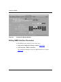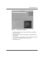
1
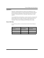
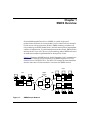
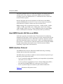
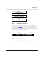
Configuring SMDS
Router Software Version 11.0
Site Manager Software Version 5.0
Part No. 114069 Rev. A
August 1996
4401 Great America Parkway
Santa Clara, CA 95054
8 Federal Street
Billerica, MA 01821
Copyright © 1988–1996 Bay Networks, Inc.
All rights reserved. Printed in the USA. August 1996.
The information in this document is subject to change without notice. The statements, configurations, technical data,
and recommendations in this document are believed to be accurate and reliable, but are presented without express or
implied warranty. Users must take full responsibility for their applications of any products specified in this document.
The information in this document is proprietary to Bay Networks, Inc.
The software described in this document is furnished under a license agreement and may only be used in accordance
with the terms of that license. A summary of the Software License is included in this document.
Restricted Rights Legend
Use, duplication, or disclosure by the United States Government is subject to restrictions as set forth in subparagraph
(c)(1)(ii) of the Rights in Technical Data and Computer Software clause at DFARS 252.227-7013.
Notice for All Other Executive Agencies
Notwithstanding any other license agreement that may pertain to, or accompany the delivery of, this computer
software, the rights of the United States Government regarding its use, reproduction, and disclosure are as set forth in
the Commercial Computer Software-Restricted Rights clause at FAR 52.227-19.
Trademarks of Bay Networks, Inc.
ACE, AFN, AN, BCN, BLN, BN, BNX, CN, FN, FRE, GAME, LN, Optivity, PPX, SynOptics, SynOptics
Communications, Wellfleet and the Wellfleet logo are registered trademarks and ANH, ASN, Bay•SIS, BCNX,
BLNX, EZ Install, EZ Internetwork, EZ LAN, PathMan, PhonePlus, Quick2Config, RouterMan, SPEX,
Bay Networks, Bay Networks Press, the Bay Networks logo and the SynOptics logo are trademarks of
Bay Networks, Inc.
Third-Party Trademarks
All other trademarks and registered trademarks are the property of their respective owners.
Statement of Conditions
In the interest of improving internal design, operational function, and/or reliability, Bay Networks, Inc. reserves the
right to make changes to the products described in this document without notice.
Bay Networks, Inc. does not assume any liability that may occur due to the use or application of the product(s) or
circuit layout(s) described herein.
Portions of the code in this software product are Copyright © 1988, Regents of the University of California. All rights
reserved. Redistribution and use in source and binary forms of such portions are permitted, provided that the above
copyright notice and this paragraph are duplicated in all such forms and that any documentation, advertising materials,
and other materials related to such distribution and use acknowledge that such portions of the software were
developed by the University of California, Berkeley. The name of the University may not be used to endorse or
promote products derived from such portions of the software without specific prior written permission.
SUCH PORTIONS OF THE SOFTWARE ARE PROVIDED “AS IS” AND WITHOUT ANY EXPRESS OR
IMPLIED WARRANTIES, INCLUDING, WITHOUT LIMITATION, THE IMPLIED WARRANTIES OF
MERCHANTABILITY AND FITNESS FOR A PARTICULAR PURPOSE.
In addition, the program and information contained herein are licensed only pursuant to a license agreement that
contains restrictions on use and disclosure (that may incorporate by reference certain limitations and notices imposed
by third parties).
ii
114069 Rev. A
Bay Networks Software License
Note: This is Bay Networks basic license document. In the absence of a
software license agreement specifying varying terms, this license -- or the
license included with the particular product -- shall govern licensee’s use of
Bay Networks software.
This Software License shall govern the licensing of all software provided to licensee by Bay Networks (“Software”).
Bay Networks will provide licensee with Software in machine-readable form and related documentation
(“Documentation”). The Software provided under this license is proprietary to Bay Networks and to third parties from
whom Bay Networks has acquired license rights. Bay Networks will not grant any Software license whatsoever, either
explicitly or implicitly, except by acceptance of an order for either Software or for a Bay Networks product
(“Equipment”) that is packaged with Software. Each such license is subject to the following restrictions:
1.
Upon delivery of the Software, Bay Networks grants to licensee a personal, nontransferable, nonexclusive license
to use the Software with the Equipment with which or for which it was originally acquired, including use at any
of licensee’s facilities to which the Equipment may be transferred, for the useful life of the Equipment unless
earlier terminated by default or cancellation. Use of the Software shall be limited to such Equipment and to such
facility. Software which is licensed for use on hardware not offered by Bay Networks is not subject to restricted
use on any Equipment, however, unless otherwise specified on the Documentation, each licensed copy of such
Software may only be installed on one hardware item at any time.
2.
Licensee may use the Software with backup Equipment only if the Equipment with which or for which it was
acquired is inoperative.
3.
Licensee may make a single copy of the Software (but not firmware) for safekeeping (archives) or backup
purposes.
4.
Licensee may modify Software (but not firmware), or combine it with other software, subject to the provision
that those portions of the resulting software which incorporate Software are subject to the restrictions of this
license. Licensee shall not make the resulting software available for use by any third party.
5.
Neither title nor ownership to Software passes to licensee.
6.
Licensee shall not provide, or otherwise make available, any Software, in whole or in part, in any form, to any
third party. Third parties do not include consultants, subcontractors, or agents of licensee who have licensee’s
permission to use the Software at licensee’s facility, and who have agreed in writing to use the Software only in
accordance with the restrictions of this license.
7.
Third-party owners from whom Bay Networks has acquired license rights to software that is incorporated into
Bay Networks products shall have the right to enforce the provisions of this license against licensee.
8.
Licensee shall not remove or obscure any copyright, patent, trademark, trade secret, or similar intellectual
property or restricted rights notice within or affixed to any Software and shall reproduce and affix such notice on
any backup copy of Software or copies of software resulting from modification or combination performed by
licensee as permitted by this license.
114069 Rev. A
iii
Bay Networks Software License (continued)
9.
Licensee shall not reverse assemble, reverse compile, or in any way reverse engineer the Software. [Note: For
licensees in the European Community, the Software Directive dated 14 May 1991 (as may be amended from time
to time) shall apply for interoperability purposes. Licensee must notify Bay Networks in writing of any such
intended examination of the Software and Bay Networks may provide review and assistance.]
10. Notwithstanding any foregoing terms to the contrary, if licensee licenses the Bay Networks product “Site
Manager,” licensee may duplicate and install the Site Manager product as specified in the Documentation. This
right is granted solely as necessary for use of Site Manager on hardware installed with licensee’s network.
11. This license will automatically terminate upon improper handling of Software, such as by disclosure, or Bay
Networks may terminate this license by written notice to licensee if licensee fails to comply with any of the
material provisions of this license and fails to cure such failure within thirty (30) days after the receipt of written
notice from Bay Networks. Upon termination of this license, licensee shall discontinue all use of the Software
and return the Software and Documentation, including all copies, to Bay Networks.
12. Licensee’s obligations under this license shall survive expiration or termination of this license.
iv
114069 Rev. A
Contents
Configuring SMDS
About This Guide
Software Suites ................................................................................................................ xi
Audience ...........................................................................................................................xii
Before You Begin ..............................................................................................................xii
Conventions .....................................................................................................................xiii
Acronyms .........................................................................................................................xiv
Ordering Bay Networks Publications ............................................................................... xv
Technical Support and Online Services
Bay Networks Customer Service ................................................................................... xviii
Bay Networks Information Services .................................................................................xix
World Wide Web ........................................................................................................xix
Customer Service FTP ..............................................................................................xix
Support Source CD ................................................................................................... xx
CompuServe ............................................................................................................. xx
InfoFACTS .................................................................................................................xxi
How to Get Help ........................................................................................................xxi
Chapter 1
SMDS Overview
How SMDS Sends LAN Data over WANs .......................................................................1-2
SMDS Interface Protocol ................................................................................................1-2
Data Exchange Interface Protocol ..................................................................................1-4
PDU Assembly .........................................................................................................1-4
SMDS Individual Addresses ...........................................................................................1-7
SMDS Group Addresses ................................................................................................1-7
For More Information about SMDS .................................................................................1-7
114069 Rev. A
v
Chapter 2
Implementation Notes
Requirements for the Router and the DSU/CSU ............................................................2-3
DXI Protocol Requirements ......................................................................................2-3
Local Management Interface ....................................................................................2-3
Protocols Supported by SMDS .......................................................................................2-4
Priority of Heartbeat Poll Messages ...............................................................................2-4
Multinet ...........................................................................................................................2-5
Multigroup .......................................................................................................................2-7
Configuring Synchronous Lines for SMDS ...................................................................2-10
Chapter 3
Enabling SMDS
Using the MIB Object ID .................................................................................................3-1
Enabling SMDS on an Interface .....................................................................................3-2
Chapter 4
Editing SMDS Parameters
Editing SMDS Interface Parameters ...............................................................................4-2
SMDS Interface Parameter Descriptions .................................................................4-4
Deleting SMDS from the Router .....................................................................................4-8
Appendix A
SMDS Default Settings
Index
vi
114069 Rev. A
Figures
Figure 1-1.
Figure 1-2.
Figure 1-3.
Figure 1-4.
Figure 1-5.
Figure 2-1.
Figure 2-2.
SMDS Sample Network ...........................................................................1-1
SMDS Interface Protocol Stack ...............................................................1-3
SMDS Level-3 PDU .................................................................................1-3
DXI Protocol .............................................................................................1-4
DXI Packet Assembly ...............................................................................1-6
Access to SMDS Network via a Router and DSU/CSU ...........................2-1
Low-Speed Access to SMDS Network .....................................................2-2
Figure 2-3.
Figure 2-4.
Figure 2-5.
Figure 2-6.
Figure 2-7.
Figure 3-1.
Figure 4-1.
Figure 4-2.
Low-Speed Access to SMDS Network via a Low-Speed DSU ................2-2
SMDS and IP Addresses for a Multinet Configuration .............................2-5
Multinet Configuration ..............................................................................2-6
Multigrouping SMDS and IP Addresses ...................................................2-7
Multigroup Configuration ..........................................................................2-9
SMDS Configuration Window ...................................................................3-2
Configuration Manager Window ...............................................................4-2
SMDS Interface List Window ...................................................................4-3
114069 Rev. A
vii
Tables
Table 2-1.
Table A-1.
114069 Rev. A
Synchronous Line Parameter Settings for SMDS ..................................2-10
SMDS Interface Parameters ................................................................... A-1
ix
About This Guide
If you are responsible for configuring and managing Bay Networks routers or
BNX platforms, read this guide to learn how to customize Bay Networks software
for Switched Multimegabit Data Services (SMDS).
This guide, Configuring SMDS, offers
•
An overview of the SMDS protocol (Chapter 1)
•
Implementation notes that may affect how you configure SMDS
(Chapter 2)
•
Instructions on enabling SMDS on your router (Chapter 3)
•
Instructions on editing SMDS interface parameters and configuring SMDS
(Chapter 4)
Software Suites
Routing and Switching software is available in the following suites:
114069 Rev. A
•
The System Suite includes IP routing, 802.1 Transparent Bridge, Source Route
Bridge, Translation Bridge, SNMP Agent, Bay Networks HDLC, PPP, OSPF,
EGP, BGP, and basic DLSw.
•
The LAN Suite includes DECnet Phase 4, AppleTalk Phase 2, OSI, VINES,
IPX, and ATM DXI, in addition to the System Suite.
•
The WAN Suite includes ATM DXI, Frame Relay, LAPB, and X.25, in
addition to the System Suite.
•
The Corporate Suite includes the System, LAN, and WAN suites in their
entirety.
•
The ARE ATM Suite provides RFC 1483 and 1577 compliance, ATM UNI 3.0
signaling, in addition to the LAN Suite.
xi
Configuring SMDS
The ARE VNR Corporate Suite provides ATM Forum LAN Emulation, in addition
to the ARE ATM Suite and Corporate Suite.
•
The BNX Suite includes IP Routing, SNMP Agent, Bay Networks HDLC,
PPP, OSPF, EGP, BGP, File-Based Performance Statistics, Frame Relay
switching, and Frame Relay billing, and selected components from the
Corporate, ARE ATM, and ARE VNR Corporate suites.
Availability of features and functionality described in this guide depends on the
suites you are using.
Audience
Written for system and network managers, this guide provides instructions on how
to configure the Bay Networks implementation of SMDS interfaces to suit your
environment.
We assume that you have experience with LANs and WANs, SMDS, and general
network management tasks.
Before You Begin
Before using this guide, you must complete the following procedures:
•
Create and save a configuration file that has at least one SMDS interface.
•
Retrieve the configuration file in local, remote, or dynamic mode.
For instructions, refer to Configuring Routers or Configuring Customer Access
and Trunks (BNX Software), depending on the type of installed software.
xii
114069 Rev. A
About This Guide
Conventions
bold text
Indicates text that you need to enter, command names,
and buttons in menu paths.
Example: Enter wfsm &
Example: Use the dinfo command.
Example: ATM DXI > Interfaces > PVCs identifies the
PVCs button in the window that appears when you
select the Interfaces option from the ATM DXI menu.
italic text
Indicates variable values in command syntax
descriptions, new terms, file and directory names, and
book titles.
quotation marks (“ ”)
Indicate the title of a chapter or section within a book.
screen text
Indicates data that appears on the screen.
Example: Set Bay Networks Trap Monitor Filters
separator ( > )
Separates menu and option names in instructions and
internal pin-to-pin wire connections.
Example: Protocols > AppleTalk identifies the
AppleTalk option in the Protocols menu.
Example: Pin 7 > 19 > 20
vertical line (|)
Indicates that you enter only one of the parts of the
command. The vertical line separates choices. Do not
type the vertical line when entering the command.
Example: If the command syntax is
show at routes | nets, you enter either
show at routes or show at nets, but not both.
114069 Rev. A
xiii
Configuring SMDS
Acronyms
xiv
ARP
Address Resolution Protocol
ATM
Asynchronous Transfer Mode
CRC
Cyclic Redundancy Check
DSU/CSU
Digital Service Unit/Channel Service Unit
DS1
Digital Service, Level 1
DS3
Digital Service, Level 3
DXI
data exchange interface
HSSI
high-speed serial interface
IEEE
Institute of Electrical and Electronic Engineers
IP
Internet Protocol
IPX
Internet Packet Exchange
LAN
local area network
LMI
Local Management Interface
MAC
media access control
MAN
metropolitan area network
OSI
Open Systems Interconnection
OSPF
Open Shortest Path First
PDU
protocol data unit
PVCs
permanent virtual circuits
RIP
Routing Information Protocol
SIP
SMDS Interface Protocol
SMDS
Switched Multimegabit Data Services
SNI
subscriber network interface
SNMP
Simple Network Management Protocol
WAN
wide area network
XNS
Xerox Network System
114069 Rev. A
About This Guide
Ordering Bay Networks Publications
To purchase additional copies of this document or other Bay Networks
publications, order by part number from the Bay Networks Press™ at the following
telephone or fax numbers:
• Telephone - U.S./Canada
• Telephone - International
• Fax
1-888-4BAYPRESS
1-510-490-4752
1-510-498-2609
You can also use these numbers to request a free catalog of Bay Networks Press
product publications.
114069 Rev. A
xv
Technical Support and Online Services
To ensure comprehensive network support to our customers and partners
worldwide, Bay Networks Customer Service has Technical Response Centers
in key locations around the globe:
•
•
•
•
•
Billerica, Massachusetts
Santa Clara, California
Sydney, Australia
Tokyo, Japan
Valbonne, France
The Technical Response Centers are connected via a redundant Frame Relay
Network to a Common Problem Resolution system, enabling them to transmit and
share information, and to provide live, around-the-clock support 365 days a year.
Bay Networks Information Services complement the Bay Networks Service
program portfolio by giving customers and partners access to the most current
technical and support information through a choice of access/retrieval means.
These include the World Wide Web, CompuServe, Support Source CD, Customer
Support FTP, and InfoFACTS document fax service.
114069 Rev. A
xvii
Configuring SMDS
Bay Networks Customer Service
If you purchased your Bay Networks product from a distributor or authorized
reseller, contact that distributor’s or reseller’s technical support staff for assistance
with installation, configuration, troubleshooting, or integration issues.
Customers can also purchase direct support from Bay Networks through a variety
of service programs. As part of our PhonePlus™ program, Bay Networks Service
sets the industry standard, with 24-hour, 7-days-a-week telephone support
available worldwide at no extra cost. Our complete range of contract and
noncontract services also includes equipment staging and integration, installation
support, on-site services, and replacement parts delivery -- within approximately
4 hours.
To purchase any of the Bay Networks support programs, or if you have questions
on program features, use the following numbers:
Region
Telephone Number
Fax Number
United States and
Canada
1-800-2LANWAN; enter Express Routing
Code (ERC) 290 when prompted
(508) 670-8766
(508) 436-8880 (direct)
Europe
(33) 92-968-300
(33) 92-968-301
Asia/Pacific Region
(612) 9927-8800
(612) 9927-8811
Latin America
(407) 997-1713
(407) 997-1714
In addition, you can receive information on support programs from your local
Bay Networks field sales office, or purchase Bay Networks support directly
from your authorized partner.
xviii
114069 Rev. A
Technical Support and Online Services
Bay Networks Information Services
Bay Networks Information Services provide up-to-date support information as a
first-line resource for network administration, expansion, and maintenance. This
information is available from a variety of sources.
World Wide Web
The Bay Networks Customer Support Web Server offers a diverse library of
technical documents, software agents, and other important technical information
to Bay Networks customers and partners.
A special benefit for contracted customers and resellers is the ability to access the
Web Server to perform Case Management. This feature enables your support staff
to interact directly with the network experts in our worldwide Technical Response
Centers. A registered contact with a valid Site ID can
•
View a listing of support cases and determine the current status of any open
case. Case history data includes severity designation, and telephone, e-mail,
or other logs associated with the case.
•
Customize the listing of cases according to a variety of criteria, including
date, severity, status, and case ID.
•
Log notes to existing open cases.
•
Create new cases for rapid, efficient handling of noncritical network
situations.
•
Communicate directly via e-mail with the specific technical resources
assigned to your case.
The Bay Networks URL is http://www.baynetworks.com. Customer Service is a
menu item on that home page.
Customer Service FTP
Accessible via URL ftp://support.baynetworks.com (134.177.3.26), this site
combines and organizes support files and documentation from across the
Bay Networks product suite, including switching products from our Centillion™
and Xylogics® business units. Central management and sponsorship of this FTP
site lets you quickly locate information on any of your Bay Networks products.
114069 Rev. A
xix
Configuring SMDS
Support Source CD
This CD-ROM -- sent quarterly to all contracted customers -- is a complete Bay
Networks Service troubleshooting knowledge database with an intelligent text
search engine.
The Support Source CD contains extracts from our problem-tracking database;
information from the Bay Networks Forum on CompuServe; comprehensive
technical documentation, such as Customer Support Bulletins, Release Notes,
software patches and fixes; and complete information on all Bay Networks
Service programs.
You can run a single version on Macintosh Windows 3.1, Windows 95,
Windows NT, DOS, or UNIX computing platforms. A Web links feature enables
you to go directly from the CD to various Bay Networks Web pages.
CompuServe
For assistance with noncritical network support issues, Bay Networks Information
Services maintain an active forum on CompuServe, a global bulletin-board
system. This forum provides file services, technology conferences, and a message
section to get assistance from other users.
The message section is monitored by Bay Networks engineers, who provide
assistance wherever possible. Customers and resellers holding Bay Networks
service contracts also have access to special libraries for advanced levels of
support documentation and software. To take advantage of CompuServe’s recently
enhanced menu options, the Bay Networks Forum has been re-engineered to allow
links to our Web sites and FTP sites.
We recommend the use of CompuServe Information Manager software to access
these Bay Networks Information Services resources. To open an account and
receive a local dial-up number in the United States, call CompuServe at
1-800-524-3388. Outside the United States, call 1-614-529-1349, or your nearest
CompuServe office. Ask for Representative No. 591. When you are on line with
your CompuServe account, you can reach us with the command GO BAYNET.
xx
114069 Rev. A
Technical Support and Online Services
InfoFACTS
InfoFACTS is the Bay Networks free 24-hour fax-on-demand service. This
automated system has libraries of technical and product documents designed to
help you manage and troubleshoot your Bay Networks products. The system
responds to a fax from the caller or to a third party within minutes of being
accessed.
To use InfoFACTS in the United States or Canada, call toll-free 1-800-786-3228.
Outside North America, toll calls can be made to 1-408-764-1002. In Europe,
toll-free numbers are also available for contacting both InfoFACTS and
CompuServe. Please check our Web page for the listing in your country.
How to Get Help
Use the following numbers to reach your Bay Networks Technical Response
Center:
114069 Rev. A
Technical Response Center Telephone Number
Fax Number
Billerica, MA
1-800-2LANWAN
(508) 670-8765
Santa Clara, CA
1-800-2LANWAN
(408) 764-1188
Valbonne, France
(33) 92-968-968
(33) 92-966-998
Sydney, Australia
(612) 9927-8800
(612) 9927-8811
Tokyo, Japan
(81) 3-5402-0180
(81) 3-5402-0173
xxi
Chapter 1
SMDS Overview
Switched Multimegabit Data Service (SMDS) is a public, high-speed,
packet-switched network service that enables you to connect local area networks
(LANs) across wide area networks (WANs). SMDS technology combines cell
relay technology and IEEE Standard 802.6, the link control protocol standard that
controls cell transmission. To send information across the network, SMDS divides
data into fixed 53-byte cells. The use of cell technology makes SMDS well suited
for traffic that consumes high bandwidth for short periods of time.
Figure 1-1 illustrates an SMDS network. In this illustration, LAN 1 communicates
to LAN 2 and 3 through a router connected to an SMDS Digital Service Unit/
Channel Service Unit (DSU/CSU). The DSU/CSU changes the frame-based data
from the router into cells that can then be sent across the SMDS network.
LAN 2
LAN 1
SMDS
Network
T3
Router
SMDS
Switch
DSU/
CSU
DSU/
CSU
SMDS
Switch
Router
LAN 3
T3
T3
SNI
SNI
DSU/
CSU
SMDS
Switch
Router
SNI
SMS0001A
Figure 1-1.
114069 Rev. A
SMDS Sample Network
1-1
Configuring SMDS
The point at which the DSU/CSU meets the network is the subscriber network
interface (SNI). This is the access point to the SMDS network. Within the
switching system of the SMDS network, T3 communication lines connect the
network switches together.
Because data traffic and network equipment are different for each SMDS
customer, SMDS defines several access classes. Access classes are speeds at
which data travels from the customer site to the network switch.
SMDS currently offers six network access classes: 1.2 Mb/s, 4 Mb/s, 10 Mb/s,
16 Mb/s, 25 Mb/s, and 34 Mb/s. The 1.2 Mb/s class is for T1 lines. Classes
4 Mb/s through 34 Mb/s are for T3 lines. SMDS also offers low-speed SMDS
classes, which operate at fractional T1/E1 speeds (56 Kb/s up to 64 Kb/s).
How SMDS Sends LAN Data over WANs
LAN data is typically connectionless data. This means that it has addressing
information in each frame, so there is no need for a prior connection between the
origination and destination devices. WAN data is typically connection-oriented
data. This means that it needs a virtual circuit -- that is, a predefined path across
physical lines -- between the two connection points prior to sending data. SMDS
provides connectionless data transfer across a wide area network without
establishing a logical end-to-end connection.
SMDS Interface Protocol
The SMDS Interface Protocol (SIP) defines SMDS addressing, formatting,
framing, and error-detection requirements.
The SIP has three levels that are similar to, but do not match, the protocol layers
that make up the OSI protocol model.
•
Level 3 specifies the addressing, formatting, and encapsulation of packet data,
referred to as Level-3 PDUs.
•
Level 2 specifies the segmentation of Level-3 Protocol Data Units (PDUs)
into short, fixed-length SMDS cells, referred to as Level-2 PDUs.
•
Level 1 specifies the physical connectivity that enables transmission.
Figure 1-2 illustrates the SIP protocol stack.
1-2
114069 Rev. A
SMDS Overview
Level 3
Encapsulates Data into PDUs
Level 2
Segments Data into 53-byte PDUs
Level 1
Prepares Level-2 PDUs for the Physical Medium
SMS0002A
Figure 1-2.
SMDS Interface Protocol Stack
SIP specifies that the SMDS source and destination addresses reside in the
Level-3 PDU header (Figure 1-3). Each header contains a MAC-level address in
an E.164 address format. E.164 formats are 64 bits long and provide both
individual and multicast addresses. Network switches use the address information
in the header to route the PDU to its destination.
Trailer
Header
LAN Packet
SMS0003A
Figure 1-3.
SMDS Level-3 PDU
One or more SMDS devices, for example DSUs and routers, can perform the tasks
of the three SIP levels, as described in the next section.
114069 Rev. A
1-3
Configuring SMDS
Data Exchange Interface Protocol
For SMDS high-speed access classes, that is, speeds from 1.2 Mb/s to 34 Mb/s,
the SMDS Interest Group (SIG) wanted to simplify the integration of SMDS into
existing network equipment, and to hasten SMDS into the market. To do this, they
divided the functions defined by the SIP levels between devices that handle local
network packets (for example, a router) and devices that interface with the digital
services provided by common carriers (a DSU/CSU).
The Data Exchange Interface (DXI) protocol defines this division of tasks and
describes the router and DSU/CSU relationship (Figure 1-4). Refer to the next
section for more information.
SMDS
Network
Router
DSU/CSU
SMDS
Switch
SMDS
Switch
DSU/CSU
Router
DXI protocol defines the router
and DSU/CSU interface
SMS0005A
Figure 1-4.
DXI Protocol
For low-speed SMDS (56 Kb/s to 64 Kb/s), the DXI is extended out to the SMDS
network. In this case, you do not need a special SMDS DSU/CSU.
PDU Assembly
SMDS PDU assembly begins when the router receives a network-generated
packet. The router takes the entire packet and encapsulates it within a 36-byte
header (containing addressing, length, and control information) and a 4-byte
trailer (containing a CRC value), thereby creating an SMDS Level-3 PDU
(Figure 1-5).
1-4
114069 Rev. A
SMDS Overview
The router next prepares the Level-3 PDU for transmission to the DSU/CSU by
encapsulating it within a DXI header and trailer that provide control information.
Upon receiving the DXI packet, the DSU/CSU strips the DXI header/trailer and
divides the Level-3 PDU into fixed-length (44-byte) units called cells. The
DSU/CSU encapsulates these cells within a 7-byte header and 2-byte trailer to
form Level-2 PDUs.
Finally, the DSU/CSU inserts an additional four bytes of framing information
between each Level-2 PDU and transmits the framed cells across a
Digital Service Level 1 (DS1) or DS3 connection to the SMDS network.
Figure 1-5 shows the assembly of SMDS cells as specified by the DXI.
114069 Rev. A
1-5
Configuring SMDS
Switch Receives LAN Packet
Level-3
Encapsulation
PAYLOAD
PAYLOAD
Switch
36-byte header
4-byte trailer
PAYLOAD
DXI header
DXI trailer
DXI
PAYLOAD
Level-2
Segmentation
DSU/CSU
4-byte trailer
PAYLOAD
PAYLOAD
7-byte 44-byte 2-byte
trailer
header cell
7-byte 44-byte 2-byte
trailer
header cell
PAYLOAD
PAYLOAD
7-byte 44-byte 2-byte
trailer
header cell
PAYLOAD
Framing field
PAYLOAD
Framing field
SMDS
Network
SMS0004A
Figure 1-5.
1-6
DXI Packet Assembly
114069 Rev. A
SMDS Overview
SMDS Individual Addresses
An SMDS individual address is a unique address that the SMDS provider assigns
to an SNI. Specifically, an individual address is a media access control layer
(MAC) address in an E.164 format. An E.164 address is a 64-bit address, which
for SMDS is similar to a phone number. For example, the phone number
(617) 555-3923 becomes individual address C161 75 55 39 23 FF FF. The C
indicates that the address is an individual address, and the 1 is a standard prefix.
There can be up to 16 individual addresses for one SNI.
SMDS Group Addresses
An SMDS group address is one address that instructs an SMDS switch to
broadcast information, such as routing information packets (RIP) and address
resolution packets (ARP), from the router to multiple destination nodes. SMDS
individual addresses within the SMDS group identify these nodes.
Like an SMDS individual address, the group address is a media access control
layer (MAC) address in an E.164 format. An E.164 address is a 64-bit address,
which for SMDS is similar to a phone number. For example, the phone number
(508) 555-1144 becomes individual address E1 50 85 55 11 44 FF FF. The E
indicates that the address is a group address and the 1 is a standard prefix.
For More Information about SMDS
The following documents provide technical details on SMDS and DXI protocol
design and implementation.
Baker, F. and Kolb, C. Definitions of Managed Objects for the DS1 Interface Type.
RFC 1232, Network Information Center (NIC), SRI International, Menlo Park,
California, May 1991.
Bellcore. Generic Requirements for SMDS Customer Network Management
Service. Technical Advisory TA-TSV-001062, Issue 2, February 1992.
Bellcore. Generic System Requirements in Support of Switched Multi-Megabit
Data Service. Technical Reference TR-TSV-000772, Issue 1, May 1991.
114069 Rev. A
1-7
Configuring SMDS
Bellcore. Local Access System Generic Requirements, Objectives, and Interfaces
in Support of Switched Multi-Megabit Data Service. Technical Reference
TR-TSV-000773, Issue 1, June 1991.
Cox, T. and Tesink, K. Definitions of Managed Objects for the DS3 Interface
Type. RFC 1233, Network Information Center (NIC), SRI International, Menlo
Park, California, May 1991.
Klessig, R. and Tesink, K. SMDS: Wide-Area Data Networking with Switched
Multi-megabit Data Service. Prentice Hall, Inc., Englewood, New Jersey, 1995.
Piscitello, D. and Lawrence, J. The Transmission of IP Datagrams over the SMDS
Service. RFC 1209, Network Information Center (NIC), SRI International, Menlo
Park, California, March 1991.
SMDS Interest Group. SMDS Data Exchange Interface Protocol (Revision 3.2).
Technical Specification SIG-TS-001/1991, October 1991.
SMDS Interest Group. SMDS DXI Local Management Interface. Technical
Specification SIG-TS-002/1992, May 1992.
The following publications provide a less technical introduction to SMDS service.
Davidson, R. and Muller, N. The Guide to SONET: Planning, Installing &
Maintaining Broadband Networks. Telecom Library, Inc., 1991.
Goldstein, F. ISDN in Perspective. Addison Wesley Publishing Company,
Reading, Massachusetts, 1992.
1-8
114069 Rev. A
Chapter 2
Implementation Notes
This chapter provides information about the Bay Networks implementation of
SMDS. Specifically, it contains information about the router’s DXI protocol
requirements and the Local Management Interface protocol. This chapter also
supplies details on the use of SMDS group and individual addresses for multinet
and multigroup configurations.
To implement high-speed SMDS, you need a Bay Networks router and an SMDS
DSU/CSU that provides DS1- or DS3-based access to the switched SMDS
network. A synchronous or high-speed serial interface (HSSI) physically connects
the router and the DSU/CSU (Figure 2-1).
DSU/CSU
Router
SMDS
Network
HSSI
or
Sychronous
Interface
SMS0006A
Figure 2-1.
Access to SMDS Network via a Router and DSU/CSU
The router also supports low-speed SMDS through the SNI and DXI
specifications standardized by the SMDS Interest Group. If you are running
low-speed SMDS, you can extend the DXI to the SMDS network, thereby
eliminating the need for a special SMDS DSU/CSU. Any synchronous interface,
including MCT1 or MCE1 link modules, physically connects the router and the
network (Figure 2-2).
114069 Rev. A
2-1
Configuring SMDS
SMDS
Network
Router
Synchronous or
MCT1/MCE1
Interface
(Low speed only)
SMS0011A
Figure 2-2.
Low-Speed Access to SMDS Network
Another low-speed SMDS option is to use a low-speed DSU/CSU to connect to
the network. In this case, a V.35 cable physically connects the router to the
DSU/CSU (Figure 2-3).
Low-Speed
DSU/CSU
Router
SMDS
Network
V.35
Interface
SMS0012A
Figure 2-3.
2-2
Low-Speed Access to SMDS Network via a Low-Speed DSU
114069 Rev. A
Implementation Notes
Requirements for the Router and the DSU/CSU
The next sections provide configuration requirements for the router and the
DSU/CSU to implement high-speed SMDS.
DXI Protocol Requirements
Version 3.2 of the DXI protocol manages the data exchange between the router
and the DSU/CSU. Because the router does not support earlier DXI versions, the
DSU/CSU must support DXI Version 3.2. DXI Version 3.2 provides an optional
heartbeat poll mechanism to periodically verify the router and DSU/CSU
connection. Be sure to enable heartbeat polling on the DSU/CSU.
The DXI also provides support for both 16-bit and 32-bit cyclic-redundancy
checks (CRCs). Network devices use CRCs to check data for transmission errors.
When the router or DSU/CSU receives data, each reads the CRC character and
compares the value it calculates to the actual CRC character in the data packet.
Ensure that the CRC values for the router and the DSU/CSU match. This means
that if you set the router to 16-bit CRCs, you must set the DSU/CSU to 16-bit
CRCs. If necessary, you can modify the CRC values (16-bit or 32-bit) for both
synchronous and HSSI connections.
Local Management Interface
The Local Management Interface (LMI) protocol works with the DXI to enable
the router and the DSU/CSU to exchange management information. The LMI uses
a subset of the Simple Network Management Protocol (SNMP) to provide for
router management queries, DSU/CSU responses to queries, and DSU/
CSU-generated asynchronous trap events.
Before enabling the LMI on the router, ensure that the DSU/CSU supports this
protocol and that you enable it on the DSU/CSU.
114069 Rev. A
2-3
Configuring SMDS
Protocols Supported by SMDS
SMDS can operate with the following protocols:
•
AppleTalk
•
APPN
•
Bridge (including Spanning Tree)
•
DECnet IV
•
DLSw
•
Internet Protocol (IP), including Address Resolution Protocol (ARP) support
•
Internet Packet Exchange (IPX)
•
LLC2
•
Native Mode LAN
•
Source Routing with Bay Networks 8101 encapsulation
•
Source Routing with Spanning Tree
•
VINES
•
Xerox Network System (XNS)
Note: SMDS does not support OSI.
Priority of Heartbeat Poll Messages
When you select SMDS on a circuit, the router automatically assigns the highest
priority to heartbeat poll and LMI messages that it sends to the DSU/CSU. The
heartbeat poll and LMI messages must have priority over other data to ensure that
during heavy traffic conditions, the link stays up and allows these messages to get
through to the DSU/CSU.
2-4
114069 Rev. A
Implementation Notes
Multinet
Multinet, a feature of the Internet Protocol (IP), allows you to support many IP
networks over one SMDS line by allowing many hosts on a single logical IP
subnetwork. A multinet network is economical because you do not have to
purchase as many SMDS group addresses from your SMDS provider as you might
with other configurations.
Multinet configurations enable you to configure one SMDS individual address and
one SMDS group address for a single SNI and then associate many logical IP
subnetworks with these single SMDS addresses. A logical IP subnetwork is a host
that is directly connected to the SMDS network.
A second variation of a multinet configuration allows you to have multiple SMDS
individual addresses along with a single SMDS group address by configuring an
individual address per IP host address for the same group address. For information
about IP, refer to Configuring IP Services.
Figure 2-4 shows the two types of multinet configurations.
Type 1
Single group and individual addresses, multiple IP address
Group Address
Individual Address
lP Address
lP Address
lP Address
Type 2
Single group address, multiple individual and IP address
Group Address
Individual Address
Individual Address
Individual Address
lP Address
lP Address
lP Address
SMS0010A
Figure 2-4.
SMDS and IP Addresses for a Multinet Configuration
Figure 2-5 on page 2-6 shows a sample multinet configuration, where several IP
networks are using one SNI. Each side of the network shows a different use of
group and individual addresses for connecting to the IP networks. A multinet
configuration allows for efficient network addressing and a cost-effective method
of implementing SMDS.
114069 Rev. A
2-5
Configuring SMDS
Router
Single Group Address
for a single SNI
IP Address: 128.1.1.1
Addr. Mask: 255.255.255.0
Individual Address:
C14089991000FFFF
Group and ARP Address:
E18008881000FFFF
SMDS
Network
Individual Address:
C14089991001FFFF
Group and ARP Address:
E18008881000FFFF
Single
Group
Addresses
for a
single SNI
Individual Address:
C14089991002FFFF
Group and ARP Address:
E18008881000FFFF
Router
IP Address: 128.1.1.4
Addr. Mask: 255.255.255.0
IP Address: 150.50.1.1
Addr. Mask: 255.255.255.0
This side shows one Group Address with
many Individual and IP Addresses
Individual Address:
C14089991003FFFF
Group and ARP Address:
E18008881000FFFF
Router
IP Address: 128.1.1.2
Addr. Mask: 255.255.255.0
IP Address: 150.50.1.2
Addr. Mask: 255.255.255.0
This side shows one Group Address
with one Individual Address and
many IP Addresses
Key
Logical IP interface
Physical SMDS line
SMS0007A
Figure 2-5.
2-6
Multinet Configuration
114069 Rev. A
Implementation Notes
To configure multinet, follow these steps:
1.
In your SMDS configuration parameters, enter addresses in the Group
Address, ARP Address, and Individual Address parameters described in
Chapter 3 of this book.
2.
In your IP interface configuration, enter the same addresses that you
entered in the SMDS parameters in the previous step.
The equivalent IP parameters are SMDS Group Address, SMDS ARP Req
Address, and MAC address. Refer to Configuring IP Services for information
about these IP parameters.
3.
Add a new IP interface with a unique IP address, which includes a
network/subnet and host address.
4.
Enter the same Group Address, ARP Address, and Individual Address
that you entered in Step 2 for this new IP interface.
Note: You may also configure many individual addresses for an SMDS group
address, but ensure that each individual address within a group is unique.
Multigroup
Multigroup is a feature of the Internet Protocol (IP) that enables you to configure
multiple SMDS group addresses on the same SNI, which is the access interface to
the SMDS network. The router implements multigroup according to RFC 1209.
For information about IP, refer to Configuring IP Services.
Figure 2-6 shows a multigroup configuration.
Group Address
Group Address
Group Address
Individual Address
Individual Address
Individual Address
lP Address
lP Address
lP Address
SMS0009A
Figure 2-6.
Multigrouping SMDS and IP Addresses
Once you configure an SMDS group address, you can then assign this group
address to at least one IP subnetwork. An IP address identifies the subnetwork.
114069 Rev. A
2-7
Configuring SMDS
By associating or pairing a different SMDS group address with each IP address,
you achieve multigrouping. A multigroup configuration enables you to use one
SMDS physical line (SNI) to connect many nodes located on different
subnetworks. It also allows you to limit broadcast and multicast traffic, such as
Routing Information Protocol (RIP) updates, Address Resolution Protocol (ARP)
updates, and Open Shortest Path First (OSFP) messages, to their respective SMDS
groups.
For example, in Figure 2-7, two separate subnetworks share the same SNI. The
routers in these networks use RIP updates to communicate network information.
The routers broadcast RIP updates to each node on the network. Because each RIP
network shares an SNI, the only way to prevent RIP updates from interfering with
one another is to isolate these subnetworks by associating each one with a
different SMDS group address.
2-8
114069 Rev. A
Implementation Notes
Router
IP Address: 128.1.1.1
Addr. Mask: 255.255.255.0
Single Group Addresses
for a single SNI
Individual Address:
C14089991000FFFF
Group and ARP Address:
E18008881000FFFF
SMDS
Network
Individual Address:
C14089991001FFFF
Group and ARP Address:
E18008881000FFFF
Individual Address:
C14089991003FFFF
Group and ARP Address:
E18008881000FFFF
Multiple Group Addresses
for a single SNI
Multiple Group Addresses
for a single SNI
Individual Address:
C14089991002FFFF
Group and ARP Address:
E18008882000FFFF
Individual Address:
C14089991004FFFF
Group and ARP Address:
E18008882000FFFF
Router
IP Address: 128.1.1.3
Addr. Mask: 255.255.255.0
IP Address: 150.50.1.2
Addr. Mask: 255.255.255.0
Router
IP Address: 128.1.1.2
Addr. Mask: 255.255.255.0
IP Address: 150.50.1.1
Addr. Mask: 255.255.255.0
Key
Logical IP interface
Physical SMDS line
SMS0008A
Figure 2-7.
114069 Rev. A
Multigroup Configuration
2-9
Configuring SMDS
To configure multigroup, follow these steps:
1.
In your SMDS configuration parameters, enter addresses in the Group
Address, ARP Address, and Individual Address parameters described in
Chapter 3 of this book.
2.
In your IP interface configuration, enter the same addresses that you
entered in the SMDS parameters in the previous step.
The equivalent IP parameters are SMDS Group Address, SMDS ARP Req
Address, and MAC address. Refer to Configuring IP Services for information
about IP these parameters.
3.
Add a new IP interface with a unique IP subnetwork address. This
address should include a network/subnet and host address.
4.
Enter a new Group Address, ARP Address, and Individual Address for
this new IP interface.
The IP interface parameters override these same parameters in the SMDS
configuration for this and subsequent IP interfaces.
Configuring Synchronous Lines for SMDS
If you enable SMDS on a circuit, Site Manager automatically sets the following
synchronous line parameters.
Table 2-1.
Synchronous Line Parameter Settings for SMDS
Parameter
Value
BOFL
Disable
Promiscuous
Enable
Service
Transparent
WAN Protocol
SMDS
For more information on these parameters, refer to Configuring Routers or
Configuring Customer Access and Trunks (BNX Software), depending on the type
of installed software.
2-10
114069 Rev. A
Chapter 3
Enabling SMDS
This chapter provides information on how to enable SMDS. It assumes you have
read Configuring Routers or Configuring Customer Access and Trunks (BNX
Software), depending on the type of installed software, and that you have
1. Opened a configuration file
2. Specified router hardware, if this is a local mode configuration file
3. Selected the link or net module connector on which you are enabling SMDS
When you enable SMDS, you need to configure only a few parameters. The
Configuration Manager supplies default values for the remaining parameters. If
you want to edit these default values, refer to Chapter 4 for instructions.
Using the MIB Object ID
For each parameter, this chapter and Chapter 4 include default settings, valid
parameter options, the parameter function, instructions for setting the parameter,
and the Management Information Base (MIB) object ID.
The Technician Interface allows you to modify parameters by issuing set and
commit commands with the MIB object ID. This process is equivalent to
modifying parameters using Site Manager. For more information about using the
Technician Interface to access the MIB, refer to Using Technician Interface
Software.
Caution: The Technician Interface does not verify that the value you enter for
a parameter is valid. Entering an invalid value can corrupt your configuration.
114069 Rev. A
3-1
Configuring SMDS
Enabling SMDS on an Interface
To enable SMDS on an interface, complete the following steps.
1.
Select SMDS from the WAN Protocols menu; this menu appears after
you select a link or net module connector that requires a WAN circuit.
Site Manager automatically enables protocol prioritization when you select
SMDS. For detailed information on protocol prioritization, refer to
Configuring Traffic Filters and Protocol Prioritization.
2.
Click on OK to enable default SMDS.
The Configuration Manager displays the SMDS Configuration window
(Figure 3-1).
3.
Configure the SMDS parameters (Individual Address, Group Address,
and ARP Address) using the descriptions that follow as a guide.
4.
When you have configured all the parameters, you can do one of the
following:
-- Enable default SMDS. To do this, click on OK.
-- Edit the default values. To do this, click on Details. (Refer to Chapter 4
for instructions.)
Figure 3-1.
3-2
SMDS Configuration Window
114069 Rev. A
Enabling SMDS
Parameter:
Individual Address
Default:
C1FFFFFFFFFFFFFF
Options:
A complete SMDS E.164 address specified by the SMDS subscription
agreement that you have with your SMDS provider
Function:
Instructions:
Provides a MAC-layer address.
Enter the complete SMDS E.164 address; for example,
C15085558734FFFF.
To configure this parameter for a multigroup or multinet configuration,
refer to Chapter 2 for instructions. For information about IP, refer to
Configuring IP Services.
MIB Object ID:
Parameter:
1.3.6.1.4.1.18.3.5.9.3.1.5
Group Address
Default:
E1FFFFFFFFFFFFFF
Options:
A complete SMDS E.164 address specified by the SMDS subscription
agreement that you have with your SMDS provider
Function:
Instructions:
Provides a MAC-layer multicast address for this SMDS interface.
Enter the complete SMDS E.164 group address, for example,
E16175552876FFFF.
To configure this parameter for a multigroup or multinet configuration,
refer to Chapter 2 for instructions. For information about IP, refer to
Configuring IP Services.
MIB Object ID:
114069 Rev. A
1.3.6.1.4.1.18.3.5.9.3.1.6
3-3
Configuring SMDS
Parameter:
ARP Address
Default:
E1FFFFFFFFFFFFFF
Options:
A complete SMDS E.164 address specified by the SMDS subscription
agreement that you have with your SMDS provider
Function:
Instructions:
Provides an address resolution multicast address.
Enter the complete SMDS E.164 address, for example,
E16175552876FFFF.
To configure this parameter for a multigroup or multinet configuration,
refer to Chapter 2 for instructions. For information about IP, refer to
Configuring IP Services.
MIB Object ID:
3-4
1.3.6.1.4.1.18.3.5.9.3.1.7
114069 Rev. A
Chapter 4
Editing SMDS Parameters
This chapter provides details on how to edit SMDS parameters for the SMDS
interfaces on your router.
Note: You must have already configured at least one SMDS interface on the
router to edit SMDS parameters. If you have not yet configured an SMDS
interface, or want to add additional interfaces, see Configuring Routers or
Configuring Customer Access and Trunks (BNX Software), depending on the
type of installed software.
Access SMDS parameters from the Configuration Manager window (Figure 4-1).
Refer to Configuring Routers or Configuring Customer Access and Trunks (BNX
Software), depending on the type of installed software, for instructions on how to
access this window.
114069 Rev. A
4-1
Configuring SMDS
Figure 4-1.
Configuration Manager Window
Editing SMDS Interface Parameters
To edit SMDS interface parameters, follow these steps:
1.
Begin at the Configuration Manager window (Figure 4-1).
2.
Select Protocols > SMDS > Interfaces.
The Configuration Manager displays the SMDS Interface List window
(Figure 4-2).
4-2
114069 Rev. A
Editing SMDS Parameters
Figure 4-2.
114069 Rev. A
SMDS Interface List Window
3.
Select the interface you want to edit from the scroll box in the SMDS
Interface List window.
4.
Edit the parameters, referring to the parameter descriptions following
this procedure.
5.
Click on Apply to save your changes when you are finished. Repeat Steps
3 through 5 for each SMDS interface you want to edit.
6.
Click on Done to exit.
4-3
Configuring SMDS
SMDS Interface Parameter Descriptions
Use the following descriptions as guidelines when you edit the SMDS interface
parameters.
Parameter:
Enable
Default:
Enable
Options:
Enable | Disable
Function:
Instructions:
MIB Object ID:
Parameter:
Enables or disables SMDS on this interface.
Set to Disable if you want to temporarily disable SMDS on this interface,
rather than delete it. Set this parameter to Enable if you want to re-enable
SMDS.
1.3.6.1.4.1.18.3.5.9.3.1.2
Individual Address
Default:
C1FFFFFFFFFFFFFF
Options:
A complete SMDS E.164 address specified by the SMDS subscription
agreement that you have with your SMDS provider
Function:
Provides a MAC-layer address. The Configuration Manager fills in this
field based on your original SMDS interface configuration.
Instructions:
Enter the new SMDS E.164 address, for example, C15085558734FFFF.
To configure this parameter for a multinet or multigroup configuration,
refer to Chapter 2 for instructions.
MIB Object ID:
4-4
1.3.6.1.4.1.18.3.5.9.3.1.5
114069 Rev. A
Editing SMDS Parameters
Parameter:
Group Address
Default:
E1FFFFFFFFFFFFFF
Options:
A complete SMDS E.164 address specified by the SMDS subscription
agreement that you have with your SMDS provider
Function:
Provides a MAC-layer multicast address for this SMDS interface. The
Configuration Manager fills in this field based on your original SMDS
interface configuration.
Instructions:
Enter the new SMDS E.164 group address, for example,
E16175552876FFFF.
To configure this parameter for a multinet or multigroup configuration,
refer to Chapter 2 for instructions.
MIB Object ID:
Parameter:
1.3.6.1.4.1.18.3.5.9.3.1.6
ARP Address
Default:
E1FFFFFFFFFFFFFF
Options:
A complete SMDS E.164 address specified by the SMDS subscription
agreement that you have with your SMDS provider
Function:
Instructions:
Provides an address resolution multicast address. The Configuration
Manager fills in this field based on your original SMDS interface
configuration.
Enter the new SMDS E.164 address, for example, E16175552876FFFF.
To configure this parameter for a multinet or multigroup configuration,
refer to Chapter 2 for instructions.
MIB Object ID:
114069 Rev. A
1.3.6.1.4.1.18.3.5.9.3.1.7
4-5
Configuring SMDS
Parameter:
Heartbeat Poll
Default:
Enable
Options:
Enable | Disable
Function:
Enables or disables DXI heartbeat polling.
DXI Version 3.2 provides a heartbeat polling mechanism, which verifies
the integrity of the router/DSU connection. To implement heartbeat
polling, the router transmits a constant stream of keep-alive messages to
the DSU. The DSU, in turn, sends an acknowledgment to the router.
Instructions:
MIB Object ID:
1.3.6.1.4.1.18.3.5.9.3.1.8
Parameter:
Heartbeat Poll Interval
Default:
Range:
10 seconds
6 to 1023 seconds
Function:
Specifies the time interval between each heartbeat poll message that the
router transmits. If you disable heartbeat polling, this parameter is
nonfunctional.
Instructions:
Enter the number of seconds between the transmission of heartbeat poll
messages. Be sure to set the Heartbeat Poll Interval parameter to a value
greater than 5 seconds, the length of the heartbeat poll acknowledgment
timer. We recommend that you accept the default value.
MIB Object ID:
4-6
Set to Enable to enable heartbeat polling. Set to Disable if the DSU/CSU
in your network does not support heartbeat polling.
1.3.6.1.4.1.18.3.5.9.3.1.9
114069 Rev. A
Editing SMDS Parameters
Parameter:
Default:
Range:
Function:
Instructions:
MIB Object ID:
Parameter:
Heartbeat Poll Down Count
3 messages
1 to 1023 messages
Specifies the number of heartbeat poll messages that the router will send
without acknowledgment from the DSU before it declares the router/DSU
connection down. If you disable heartbeat polling, this parameter is
nonfunctional.
Set to the number of unacknowledged heartbeat poll messages that the
router will tolerate before taking the router/DSU connection down. We
recommend that you accept the default.
1.3.6.1.4.1.18.3.5.9.3.1.10
LMI Network Mgmt
Default:
Disable
Options:
Enable | Disable
Function:
Enables or disables LMI network management.
LMI works with DXI Version 3.2. LMI is an SNMP-like protocol that
enables the router and the DSU/CSU to exchange management
information.
Instructions:
Set to Enable to use the LMI protocol. Accept the default, Disable, if the
DSU/CSU in your network does not support the LMI.
Accept the default if you have an ADC Kentrox dual-port DataSMART
T1 SMDSU. This DSU does not support the LMI protocol. Instead, rely
on heartbeat polling to determine whether the interface between the router
and the DSU is active. Use the SMDS in-band SNMP agent to manage the
DSU.
If you have a single-port DataSMART T1 SMDSU, accept the default or
upgrade the DSU software to revision 1.41, which supports LMI.
MIB Object ID:
114069 Rev. A
1.3.6.1.4.1.18.3.5.9.3.1.11
4-7
Configuring SMDS
Parameter:
Enable Incoming Address Screening
Default:
Disable
Options:
Enable | Disable
Function:
Enables the router to verify the Individual and Group addresses that it
receives in the incoming frames and drop any improperly addressed
frames. It ensures that the router receives only traffic intended for it.
If the router rejects an address, one of three things may be happening:
Instructions:
MIB Object ID:
–
You did not configure the SMDS addresses according to the numbers
the service provider assigned.
–
The network is forwarding traffic to the router unnecessarily. Notify
the network provider.
–
If the router shares a network entry point with another device, the
router may be receiving that device’s traffic.
Set to Enable if you want the router to check incoming addresses and
control the calls it receives. If not, accept the default, Disable. To
determine whether the router is rejecting addresses, use the Technician
Interface script show smds stats. Refer to Using Technician Interface
Scripts for more information.
1.3.6.1.4.1.18.3.5.9.3.1.17
Deleting SMDS from the Router
To delete SMDS from all router circuits, complete the following steps:
1.
From the Configuration Manager window (refer to Figure 4-1), select
Protocols > SMDS > Delete SMDS.
The Configuration Manager prompts
Do you REALLY want to delete SMDS?
2.
Click on OK.
The Configuration Manager returns you to the Configuration Manager
window. SMDS is no longer configured on the router.
4-8
114069 Rev. A
Appendix A
SMDS Default Settings
This appendix lists the default settings for SMDS. Use the Configuration Manager
to edit any of the default settings listed here.
Table A-1.
114069 Rev. A
SMDS Interface Parameters
Parameter
Default
Enable
Enable
Individual Address
C1FFFFFFFFFFFFFF
Group Address
E1FFFFFFFFFFFFFF
ARP Address
E1FFFFFFFFFFFFFF
Heartbeat Poll
Enable
Heartbeat Poll Interval
10 seconds
Heartbeat Poll Down Count
3 messages
LMI Network Mgmt
Disable
Enable Incoming Address Screening
Disable
A-1
Art:SMS0001A.EPS 1-1
Art:SMS0002A.EPS 1-3
Art:SMS0003A.EPS 1-3
Art:SMS0005A.EPS 1-4
Art:SMS0004A.EPS 1-6
Art:SMS0006A.EPS 2-1
Art:SMS0011A.EPS 2-2
Art:SMS0012A.EPS 2-2
Art:SMS0009A.EPS 2-5
Art:SMS0010A.EPS 2-5
Art:SMS0007A.EPS 2-6
Art:SMS0009A.EPS 2-7
Art:SMS0008A.EPS 2-9
114069 Rev. A
iii
iv
114069 Rev. A
Index
A
access classes for SMDS, 1-2
addresses
group, 1-7
used for multigroup, 2-7
used for multinet, 2-5
individual, 1-7
used for multigroup, 2-7
used for multinet, 2-5
ARP Address parameter, 3-4, 4-5
B
Bay Networks
CompuServe forum, xx
Customer Service FTP, xix
home page on World Wide Web, xix
InfoFACTS service, xxi
publications, ordering, xv
support programs, xviii
Support Source CD, xx
Technical Response Center, xvii, xxi
technical support, xvii
C
CompuServe, Bay Networks forum on, xx
connections to router, 2-1
connectivity using heartbeat polling, 2-3
Customer Service FTP, xix
customer support. See getting help
cyclic-redundancy check (CRC) values, 2-3
114069 Rev. A
D
Data Exchange Interface (DXI) protocol
description, 1-4
requirements for SMDS
version supported, 2-3
defaults for SMDS parameters, A-1
deleting SMDS from the router, 4-8
DSU/CSU
configuration requirements for, 2-3
role in SMDS network, 1-4
E
E.164 addresses for SMDS, 1-3
Enable Incoming Address Screening parameter,
4-8
Enable parameter, 4-4
enabling SMDS, 3-1 to 3-4
G
getting help
from a Bay Networks Technical Response
Center, xxi
from the Support Source CD, xx
through CompuServe, xx
through Customer Service FTP, xix
through InfoFACTS service, xxi
through World Wide Web, xix
Group Address parameter, 3-3, 4-5
Index-1
Configuring SMDS
H
Heartbeat Poll Down Count parameter, 4-7
Heartbeat Poll Interval parameter, 4-6
heartbeat poll messages, 2-4
Heartbeat Poll parameter, 4-6
heartbeat polling for connections, 2-3
high-speed serial interface (HSSI) connections,
2-1
high-speed SMDS
description, 1-2
implementing, 2-1
I
IEEE Standard 802.6 used by SMDS, 1-1
implementation notes, 2-1 to 2-10
Individual Address parameter, 3-3, 4-4
InfoFACTS service, xxi
information sources on SMDS, 1-7
multinet
description, 2-5
sample configuration, 2-5
setting parameters for, 2-7
P
parameters
ARP Address, 3-4, 4-5
editing, 4-1 to 4-7
Enable, 4-4
Enable Incoming Address Screening, 4-8
Group Address, 3-3, 4-5
Heartbeat Poll, 4-6
Heartbeat Poll Down Count, 4-7
Heartbeat Poll Interval, 4-6
Individual Address, 3-3, 4-4
LMI Network Mgmt, 4-7
protocol data unit (PDU)
assembly, 1-4
definition, 1-2
protocols supported by SMDS, 2-4
L
R
line configuration. See synchronous line
configuration
LMI Network Mgmt parameter, 4-7
Local Management Interface (LMI)
enabling, 4-7
purpose of, 2-3
low-speed SMDS
description of, 1-2
implementing, 2-1
router requirements for SMDS, 2-3
M
MIB object ID, 3-1
multigroup
description, 2-7
sample configuration, 2-8
setting parameters for, 2-10
Index-2
S
SMDS
access classes description, 1-2
addresses, 1-7
defaults, A-1
deleting from the router, 4-8
enabling, 3-1 to 3-4
implementation notes, 2-1 to 2-10
information sources, 1-7
LMI, 2-3
overview of, 1-1 to 1-7
router requirements for, 2-3
sending data over WANs, 1-2
supported protocols, 2-4
SMDS Interface Protocol (SIP)
definition, 1-2
114069 Rev. A
Index
speeds for SMDS, 1-2
subscriber network interface (SNI) definition,
1-2, 2-1
Support Source CD, xx
Switched Multi-megabit Data Service.
See SMDS
synchronous line configuration, 2-10
W
World Wide Web, Bay Networks home page on,
xix
114069 Rev. A
Index-3