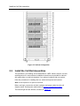
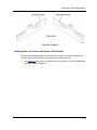
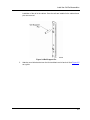
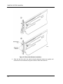
1
EXPRESS5800/A1160 HW Installation Guide Proprietary Notice and Liability Disclaimer The information disclosed in this document, including all designs and related materials, is the valuable property of NEC Corporation of America, Inc. and/or its licensors. NEC Corporation of America and/or its licensors, as appropriate, reserve all patent, copyright and other proprietary rights to this document, including all design, manufacturing, reproduction, use, and sales rights thereto, except to the extent said rights are expressly granted to others. The NEC Corporation of America product(s) discussed in this document are warranted in accordance with the terms of the Warranty Statement accompanying each product. However, actual performance of each product is dependent upon factors such as system configuration, customer data, and operator control. Since implementation by customers of each product may vary, the suitability of specific product configurations and applications must be determined by the customer and is not warranted by NEC Corporation of America. To allow for design and specification improvements, the information in this document is subject to change at any time, without notice. Reproduction of this document or portions thereof without prior written approval of NEC Corporation of America is prohibited. Trademarks Windows is a registered trademark of Microsoft Corporation. Intel and Itanium are registered trademarks of Intel Corporation. All other product, brand, or trade names used in this publication are the trademarks or registered trademarks of their respective trademark owners. PN: 456-01805-000 December, 2008 Copyright 2008 NEC Corporation of America 10850 Gold Center Drive, Suite 200, Rancho Cordova, CA 95670 All Rights Reserved Contents Section 1 Preparing for Installation ...............................................1-1 1.1. Documentation Updates..................................................................... 1-1 1.2. Customer-Provided Hardware............................................................ 1-1 1.3. Tools ................................................................................................... 1-2 1.4. Warnings and Cautions ...................................................................... 1-2 1.5. Prerequisites ...................................................................................... 1-2 1.6. Customer Support Procedures........................................................... 1-3 1.7. Cell Components................................................................................ 1-3 1.7.1. Components on the Front of a Cell .................................................... 1-3 1.7.2. Components on the Rear of a Cell ..................................................... 1-5 1.8. Receive the Hardware........................................................................ 1-6 Section 2 Preparing the Cabinet ....................................................2-1 2.1. Review the Cabinet Configuration...................................................... 2-1 2.2. Install the Cell Rail Assemblies .......................................................... 2-2 Section 3 Installing the System .....................................................3-1 3.1. Install the Cell..................................................................................... 3-1 3.2. Install the Optional Components ........................................................ 3-5 3.3. Install the Power Strips....................................................................... 3-5 Section 4 Cabling the System ........................................................4-1 4.1. Power Cabling for 100V to 120V Systems ......................................... 4-1 4.2. Power Cabling for 200V to 240V Systems ......................................... 4-2 4.2.1. Power Strip Cabling for a System with One Cell ................................ 4-5 4.2.2. Power Strip Cabling for a System with Two Cells .............................. 4-6 4.2.3. Power Strip Cabling for a System with Three Cells ............................ 4-7 4.2.4. Power Strip Cabling for a System with Four Cells.............................. 4-8 4.3. Cell Interconnect Cabling ................................................................... 4-8 4.3.1. System with Two Cells ....................................................................... 4-9 4.3.2. System with Three Cells .................................................................. 4-10 iii 4.3.3. System with Four Cells ..................................................................... 4-11 4.4. Keyboard, Monitor, and Mouse Cabling ........................................... 4-12 4.5. LAN Cabling ..................................................................................... 4-12 4.5.1. LAN Configurations .......................................................................... 4-13 4.5.2. LAN Ports ......................................................................................... 4-13 4.5.3. LAN Cabling for Systems Without an Operation LAN ...................... 4-13 4.5.4. LAN Cabling for Systems with an Operations LAN .......................... 4-14 4.6. Peripheral Cabling ........................................................................... 4-15 Section 5 Completing the Installation ........................................... 5-1 5.1. Perform Cleanup and Final Check ..................................................... 5-1 5.2. Check Cabling Before Powering On the System ............................... 5-3 5.3. Apply AC Power Initially ..................................................................... 5-4 5.3.1. Systems Operating at 100 to 120 VAC .............................................. 5-4 5.3.2. System Operating at 200 to 240 VAC ................................................ 5-5 5.4. Checking and Updating Management firmware Level and the BIOS Level ......................................................................................... 5-6 5.4.1. Initially Accessing a Partition.............................................................. 5-7 5.4.2. Checking Management Firmware Level using Remote Console Interface ............................................................................................. 5-8 5.4.3. Checking BIOS Level using Remote Console Interface .................... 5-9 5.4.4. Obtaining Releases from the Support Site ....................................... 5-10 5.4.5. Updating Management Firmware using Remote Console Interface ........................................................................................... 5-10 5.4.6. Updating BIOS on the EFI Flash Memory ........................................ 5-12 5.5. Verify PCI Card Installation .............................................................. 5-17 5.6. What to Do Next............................................................................... 5-19 Appendix A iv Related Documents and Web Resources ........ A-1 A.1 Express5800/A1160 Documentation Library ...................................... A-1 A.2 Web Resources ................................................................................. A-2 Figures Figure 1-1 System Serial Number Label Location ........................................................ 1-3 Figure 1-2 Front of the Cell ........................................................................................... 1-4 Figure 1-3 Rear of the Cell............................................................................................ 1-5 Figure 2-1 Cabinet Configuration .................................................................................. 2-2 Figure 2-2 Cell Rails ..................................................................................................... 2-3 Figure 2-3 Installing Rails ............................................................................................. 2-4 Figure 2-4 Rail Support Pin........................................................................................... 2-5 Figure 2-5 Round-Hole Bracket Installation .................................................................. 2-6 Figure 2-6 Round-Hole Bracket Installation Location ................................................... 2-7 Figure 3-1 Cell Sling ..................................................................................................... 3-2 Figure 3-2 Cell Thumbscrews ....................................................................................... 3-3 Figure 3-3 Keyhole for the Security Key ....................................................................... 3-3 Figure 3-4 Security Key Location at the time of Shipment ............................................ 3-4 Figure 3-5 Attaching the front bezel .............................................................................. 3-4 Figure 3-6 One Four-Receptacle Power Strip Installation ............................................. 3-6 Figure 3-7 Two Four-Receptacle Power Strip Installation ............................................. 3-7 Figure 4-1 Power Cable Routing for 100V to 120V Systems ........................................ 4-2 Figure 4-2 Power-Strip Power Cord Routing................................................................. 4-3 Figure 4-3 Velcro Straps for Power Strips ..................................................................... 4-4 Figure 4-4 Keyboard, Monitor, and Mouse Cabling .................................................... 4-12 Figure 4-5 LAN Cabling Configuration Without an Operation LAN ............................. 4-14 Figure 4-6 Cable Configuration for Systems with an Operations LAN ........................ 4-15 Figure 5-1 Front Rack Filler Panels .............................................................................. 5-2 Figure 5-2 Cell Cable Connections ............................................................................... 5-3 Figure 5-3 EXPRESSSCOPE® Monitor LCD After AC Power is Applied ..................... 5-4 Figure 5-4 Cell Power Cord .......................................................................................... 5-5 Figure 5-5 Power-Strip Power Cord .............................................................................. 5-6 Figure 5-6 Management Firmware Update Page.......................................................... 5-8 Figure 5-7 Management Firmware Revision Status ...................................................... 5-9 Figure 5-8 BIOS Version ............................................................................................. 5-10 v Figures Figure 5-9 Management Firmware Updates Page ...................................................... 5-11 Figure 5-10 Management Firmware Revision Status .................................................. 5-12 Figure 5-11 BIOS Front Page ..................................................................................... 5-13 Figure 5-12 BIOS Setup Window ................................................................................ 5-14 Figure 5-13 BIOS Partition Window ............................................................................ 5-15 Figure 5-14 OS Control Window ................................................................................. 5-16 Figure 5-15 BIOS Front Page ..................................................................................... 5-18 Figure 5-16 BIOS Boot Manager ................................................................................ 5-19 vi Tables Tables Table 1-1 Warnings and Cautions ................................................................................. 1-2 Table 1-2 Components on the Front of the Cell ............................................................ 1-4 Table 1-3 Components on the Rear of a Cell ................................................................ 1-5 Table 4-1 Two-Cell Interconnect Cabling ...................................................................... 4-9 Table 4-2 Three-Cell Interconnect Cabling ................................................................. 4-10 Table 4-3 Four-Cell Interconnect Cabling ................................................................... 4-11 vii Using This Guide This guide contains information that helps you install your Express5800/A1160 server. By following these installation procedures, you can help ensure a smooth and successful installation of your server. This guide is intended for system administrators and facilities personnel who are making installation of an Express5800/A1160 Server. Proper site preparation and maintenance are vital to the reliability of any computer system. As our customer, it is your responsibility to ensure that the proper facility resources and conditions are maintained. This will allow us to provide support services in accordance with the NECCare™ Maintenance and Service Warranty Program. Who Should Use This Guide This guide is intended for system administrators and facilities personnel who are preparing the site for an Express5800/A1160 server installation. Symbols and Conventions This guide uses the following text conventions and graphic symbols. Warnings, cautions, and notes have the following meanings: WARNING Warnings alert you to situations that could result in serious personal injury or loss of life. CAUTION Cautions indicate situations that can damage the system hardware or software. Note: Notes give important information about the material being described. Names of keyboard keys are printed as they appear on the keyboard. For example, Ctrl, Alt, or Enter. Text or keystrokes that you enter appear as boldface type. For example, type abc123 and press ENTER. File names are printed in uppercase letters. For example, AUTOEXEC.BAT. ix Related Documents Related Documents In addition to this guide, the following system documentation is useful. x NECCare™ Guide The NECCare Guide contains information about NEC’s warranty and server registration. Safety Notices Safety Notices WARNING To avoid a risk of injuries, maintenance procedures require trained technical personnel. In maintenance procedures with voltages of 42.4V peak or 60Vdc or more, take safety measures, such as wearing insulated rubber gloves. Performing work without these measures may cause electric shock. In an emergency, such as a dangerous event that requires turning off the power supply, turn off the breaker at the rear of the server. Turning off the breaker may cause data destruction. Therefore, users should determine when to turn off the breaker in accordance with specified operation criteria. The server is equipped with a front stabilizer. Engage the front stabilizer during installation. For stability and to distribute the weight, also attach side stabilizers. Otherwise, the rack may topple over and cause injuries. If you extend two or more devices from the rack at the same time, the rack may topple over on you. Extend only one device from the rack at a time. Exercise great care not to hurt your fingers on the rail when you mount/dismount the equipment into/from the rack. Lithium batteries can be dangerous. Improper handling of lithium batteries may result in an explosion. Dispose of lithium batteries as required by local ordinance. Replace only with the same or equivalent type battery. A liquid crystal display is used in this server. When handling a damaged liquid crystal display, take care to avoid exposure to the liquid inside the liquid crystal display. The liquid can cause bodily harm. In the event the liquid is ingested, gargle at once and consult a doctor immediately. If the liquid comes in contact with skin or gets into the eyes, wash the skin with cool running water, or flush the eye with cool running water for at least 15 minutes and consult a doctor. The DVD-ROM drive uses a laser beam. Do not look or insert a mirror inside while the system is on. A laser beam is invisible; if your eyes get exposed to it, there is a risk of losing your eyesight. Elevated Operating Ambient Temperature – If installed in a closed or multi-unit rack assembly, the operating ambient temperature of the rack environment may be greater than the room ambient environment. Therefore, consideration should be given to installing the equipment in an environment compatible with the maximum rated ambient xi Safety Notices temperature of 89.6°F. Reduced air Flow – Installation of the equipment in a rack should be such that the amount of air flow required for safe operation of the equipment is not compromised. To prevent fires, and damage to rack equipment and supply wiring, make sure that the rated load of the power branch circuit is not exceeded. Equipment nameplate ratings should be used when addressing this concern. For more information on installation and wiring of power-related facilities, contact your electrician or local power company. To prevent electrical shock, connect all rack and rack support equipment to the same electrical circuit of the building wiring. If you are unsure, check the building wiring to avoid remote earth conditions. For safe operation, only connect the equipment to a building supply that is in accordance with current wiring regulations in your country. In the USA those wiring standards are regulated by Underwriter Laboratories (UL); in the U.K. by the Institution of Electrical Engineers, (IEE) and in Canada by the Canadian Standards Association (CSA). WARNING Some locations within the server have high voltage and therefore are very dangerous. To avoid risk of electric shock, turn off all server power and disconnect power cables before working inside the server unit. The main power of your server is turned off by turning off the power source to the server or removing the power cable. Before touching the parts in the server, wait for at least 10 to 15 seconds until residual voltage is discharged. xii Online maintenance – During and after servicing, do not leave the server door open unless necessary to perform servicing. Safety Notices for Users Outside of the U.S.A. and Canada WARNING Take care not to short live components with conductive tools, such as an adjustable wrench. To prevent shock, take care not to drop or leave conductive parts, such as a screw, in the server when servicing the system. Be careful when accessing a fan or rotating parts to avoid cutting your hand or fingers. Safety inspections – When servicing the system, check equipment that can cause harm due to deterioration, and if necessary, replace the part. Safety Notices for Users Outside of the U.S.A. and Canada PELV (Protected Extra-Low Voltage) Integrity: To ensure the extra-low voltage integrity of the equipment, connect only equipment with mains-protected electrically-compatible circuits to the external ports. Remote Earths: To prevent electrical shock, connect all local (individual office) computers and computer support equipment to the same electrical circuit of the building wiring. If you are unsure, check the building wiring to avoid remote earth conditions. Earth Bonding: For safe operation, only connect the equipment to a building supply that is in accordance with current wiring regulations in your country. In the USA those wiring standards are regulated by Underwriter Laboratories (UL); in the U.K., by the Institution of Electrical Engineers, (IEE) and in Canada by the Canadian Standards Association (CSA). xiii Section 1 Preparing for Installation This installation document describes how to install your new Express5800/A1160 system. The installer must have knowledge and experience with server hardware installation. Because of the server weight, the hardware installation requires a minimum of two people to ensure a safe installation. After installing system hardware, you will also need to do the following: 1. Install Server Management software on your management server, if you have not already done so. 2. Install operating system software and Server Management software on the Express5800/A1160 partitions and then configure the software. Complete the procedures in the order in which they are shown. Depending on your specific configuration, some procedures may not apply; just skip them. 1.1. Documentation Updates This document contains all the information that was available at the time of publication. The latest version of the document may be found in the Product Support Web Site: http://support.necam.com/servers/Enterprise/ 1.2. Customer-Provided Hardware The following customer-provided hardware is required to complete the installation: y LAN cable for the maintenance LAN - CAT5 cable y Additional LAN cables (CAT5 or CAT6 — Gigabit) for connection to the public LAN y Keyboard, video, and mouse for each partition - USB keyboard and mouse for each partition - Monitor for the partition The keyboard, video display, and mouse (KVM) must be directly connected to the component during installation and cannot be redirected to a remote workstation. After installation is complete, the keyboard, video display, and 1-1 Tools mouse need not remain connected and can be removed. Multiple keyboard, video, and mouse connections can be provided by the use of a KVM switch in larger system configurations. y Dedicated Ethernet hub, router, or gateway depending on the LAN topology at your site 1.3. Tools A number 2 Phillips screwdriver is the only tool required for installation. Optionally, a 3-mm flat-blade screwdriver might be helpful when installing the cell interconnect cables. 1.4. Warnings and Cautions Observe the warnings and cautions in Table 1-1 when installing the system. Additional warnings and cautions are included as required throughout the document. Table 1-1 Warnings and Cautions Type of Note Instruction Warning Wear goggles or eye protection when cutting the bands that secure shipping containers. Warning Do not push on the upper portion of a server cabinet, and use caution when moving the cabinet on its casters. The cabinet can tip over if not handled properly. Warning Have two people lift each cell. A fully loaded cell weighs about 45 kg (100 lb). Caution Wear a wrist strap connected to a ground point when performing maintenance on the server. 1.5. Prerequisites Before beginning the system installation, ensure that all site-provided power sources and cabling are in place and that the optional (but recommended) uninterruptible power supply (UPS) is in place and functioning properly. For more information, see the System Planning Guide. 1-2 Customer Support Procedures 1.6. Customer Support Procedures If you require assistance during the installation 1. Contact the NEC Technical Support by phone (1-866-269-1239) or e-mail ([email protected]) and let the operator know that you want to open a support request. Have the system serial number available for the NEC Technical Support operator. The system serial number is on the back of the cell on the same label as the cell number. Figure 1-1 System Serial Number Label Location 1.7. Cell Components The following text identifies the main components, ports, and connectors that are visible on the front and back of a cell. 1.7.1. Components on the Front of a Cell Figure 1-2 identifies the components that are visible on the front of the cell. Table 1-2 describes each component in more detail. 1-3 Cell Components Figure 1-2 Front of the Cell Table 1-2 Components on the Front of the Cell Component 1-4 Description Fan module Provides the airflow needed to cool the cell. LED fan status indicators Provide fan status with one LED light on each fan module. A green light indicates normal operations. Drive tray Provides slots for up to six 2.5-inch SAS hard drives. Hard drives Six 2.5-inch SAS hard drives enclosed in individual drive carriers. EXPRESSSCOPE® Monitor A control and display interface for the cell and the partition containing the cell. LED fan status indicators Provide fan status with one LED light on each fan module. A green light indicates normal operations. LCD Displays status information and provides a menu of management tasks for the cell on a 4-line by 20-character liquid crystal display (LCD) panel. Refer to the User’s Guide for information on using the LCD. Power button Turns on or off power for the cell. ID button Turns on a blue LED in the back of the cell for identification purposes during servicing. A button on the back of the cell turns off the LED. Navigation buttons Enables the selection of EXPRESSSCOPE® Monitor menu options. Cell Components Component Description LED status indicators Provides status for the cell. The top light indicates power status. The bottom light indicates cell status. See the EXPRESSSCOPE® Monitor LCD or the remote console interface for additional information on the power or cell status. DVD-RW drive A DVD-RW drive for your use. Partition USB connections Provides two universal serial bus (USB) 2.0 ports. 1.7.2. Components on the Rear of a Cell Figure 1-3 identifies the components that are visible on the rear of the cell. Table 1-3 describes these components in more detail. Figure 1-3 Rear of the Cell Table 1-3 Components on the Rear of a Cell Component Description PCIe carrier/cards Six hot-plug switched PCIe 8x card slots. Slots 1 and 4 can support full-length cards. Each PCIe card is housed in an individual carrier. Cell ID An LED that is lit when the ID button on the EXPRESSSCOPE® Monitor is pressed. Press the cell ID button on the rear of the cell to turn off the light. Partition USB ports Two universal serial bus (USB) 2.0 ports. 1-5 Receive the Hardware Component Description Management serial port A 9-pin serial port for the management board. Partition serial port A 9-pin serial port for the operating system. Maintenance LAN port An RJ45 port that provides a 10/100 Mbps Ethernet network connection to the maintenance LAN. Partition video port A 15-pin SVGA port. USB management port A USB 2.0 port for use with the management board. Partition LAN ports Two RJ45 ports that provide 10/100/1000 Mbps Ethernet network connections for the operating system. These ports are typically connected to the public LAN. Navigation buttons Enables the selection of EXPRESSSCOPE® Monitor menu options. LED status indicators Provides status for the cell. The top light indicates power status. The bottom light indicates cell status. See the EXPRESSSCOPE® Monitor LCD or the remote console interface for additional information on the power or cell status. Power supplies Two power supplies that provide n+1 redundancy when used in high-voltage configurations. Each power supply has its own AC power cord. Interconnect cable connectors High-speed serial interface and management LAN connections between the cells in configurations with two or more cells. 1.8. Receive the Hardware System components are shipped to you from a number of sources. Your order may contain a number of boxes shipped from different locations. Each box containing a cell is marked to indicate which cell is contained in it. When you unpack each cell, ensure that the cell is labeled and that the label information matches the cell number indicated on its box. y Inspect the exterior of each shipping box and pallet. If any damage is visible, make an appropriate note on the shipping paperwork. y Move the packaged hardware as close to its final destination as possible. y Take an inventory of the hardware to ensure that all required items are present. To report any missing, incorrect, or defective parts during unpacking, contact the NEC Technical Support. Refer to 1.6 Customer Support Procedures 1-6 Section 2 Preparing the Cabinet Familiarize yourself with the component layout of your system and prepare your cabinet for installation. Side access to the cabinet is required for power strip installation. If the new cabinet will be placed between existing cabinets, perform 3.3 Install the Power Strips first. Then reattach the side skins and move the cabinet in place. 2.1. Review the Cabinet Configuration Figure 2-1 shows the cabinet configuration. A four-cell system starts with cell 0 at the 6U location. Smaller configurations are built similarly from the bottom of the cabinet upward, starting with cell 0 at the 6U location. This figure shows cells and optional equipment that might not be part of your order. 2-1 Install the Cell Rail Assemblies Figure 2-1 Cabinet Configuration 2.2. Install the Cell Rail Assemblies This procedure is for installing cell rail assemblies in a NEC cabinet; however, the rails are designed to fit in most cabinets. Installation instructions are provided for cabinets with square-hole or round-hole brackets. If you ordered a cabinet with your system, follow the procedures for installing rails in a cabinet with square-hole brackets. Note: A cell requires 4U of space in the frame. Before you begin, remove the cell rails, hardware, and power cables from the cell shipping carton. Set the power cables aside for Section 4 Cabling the System The left and right rails are different, as shown in Figure 2-2. 2-2 Install the Cell Rail Assemblies Figure 2-2 Cell Rails Installing Rails in a Cabinet with Square-Hole Brackets Perform the following procedure to install each set of rails. If you have a multiple-cell system, install each set of rails for all cells before installing the cells. 1. Use Figure 2-3 as a guide to install the rails in the cabinet. The figure illustrates the proper placement of each rail. 2-3 Install the Cell Rail Assemblies Figure 2-3 Installing Rails 2. Beginning with either the front or back of the rail, insert the holding tabs in the specified locations and push down until the locking spring clicks into place. 3. Repeat on the other end of the rail 4. Repeat steps 1 through 3 to install the other rail. To remove a rail, press in the locking spring with your finger or a flat-blade screwdriver and push up on the rail. Installing Rails in a Cabinet with Round-Hole Brackets If you have a multiple-cell system, perform the following procedure for each set of rails for all cells before installing the cells: 2-4 1. Locate the bracket conversion kit that is provided with the rails to convert the square-hole brackets for use in a cabinet with round-hole brackets. The kit includes two metal brackets, four screws, and two rail support pins for each rail. 2. Attach a rail support pin on each metal bracket. This pin is used to ease the Install the Cell Rail Assemblies installation of the rail in the cabinet. Once the rails are installed in the cabinet these pins are removed. Figure 2-4 Rail Support Pin 3. Attach a round-hole bracket over the front and back end of each rail. Use Figure 2-5 as a guide. 2-5 Install the Cell Rail Assemblies Figure 2-5 Round-Hole Bracket Installation 4. 2-6 Align one end of the rail in the cabinet using the alignment notches as a guide, and secure the rail to the cabinet using two screws for each side of the rail. Install the Cell Rail Assemblies Figure 2-6 Round-Hole Bracket Installation Location 5. Remove the rail support pin. 6. Repeat steps 3 and 4 to install the other rail. 2-7 Section 3 Installing the System Use the following procedures to install the hardware modules of your system. 3.1. Install the Cell Use the following procedure to install all the cells in your system. WARNING Removing the cell from the box requires two people. A fully loaded cell weighs about 50 kg (110 lb). 1. Carefully lift the cell from the box using the cell sling and place the cell on a flat surface. 3-1 Install the Cell Figure 3-1 Cell Sling 3-2 2. Remove the cell from the protective packaging, and then slide it onto the rails in the cabinet. 3. Tighten the thumbscrews to secure the cell to the cabinet. Install the Cell Figure 3-2 Cell Thumbscrews If you want to attach the bezel to the front of the Cell, follow the following steps. 1. Insert the security key into the keyhole of the front bezel. Figure 3-3 Keyhole for the Security Key 2. Turn left while pushing the security key straight to unlock. Note: At the time of shipment, the security key is located in the bag taped at the reverse side of the front bezel. 3-3 Install the Cell Figure 3-4 Security Key Location at the time of Shipment 3. Put the hooks on the reverse side of the front bezel into the holes on the left mounting frame between thumbscrews, and push the rightmost of the bezel to attach. Figure 3-5 Attaching the front bezel 4. 3-4 Insert the security key into the keyhole, and turn right to lock while pushing the Install the Optional Components security key straight. 3.2. Install the Optional Components Depending on the server you purchased, the following items might be part of your order or might be procured locally. y Keyboard/LCD monitor drawer It is recommended that the drawer be placed in the 22U or 23U location. This position enables a user of average height to use the keyboard when standing. y Keyboard, video display, mouse (KVM) switch y KVM cables y Keyboard and mouse y Video display (monitor) Follow the procedures that are supplied with the optional components to install these items in the cabinet. Some components can be installed in locations outside the cabinet. Cables are connected later as described in 4.4 Keyboard, Monitor, and Mouse Cabling. Note: If you did not purchase a keyboard, video display, and mouse with the order, you need to procure them locally. 3.3. Install the Power Strips For high-range AC power (200 to 240 V) input, the number of required power strips depends on the system configuration, which should have been determined during the system planning process. Note: Power strips are not required for systems operating at 100 to 120 volts. Several types of power strips and mounting brackets are currently available. The two most common options are y Four-receptacle power strips for use in customer-supplied cabinets y Two four-receptacle power strips in a mounting bracket for use in NEC cabinets Note: These figures show NEC cabinets and hardware. If your cabinet is not compatible with the brackets and hardware, simply discard the unused pieces. Follow these steps to install the power strips: 1. Remove the power strips from the shipping carton. 2. Attach a Velcro strap, included in the packaging with the power strips, next to each receptacle. Velcro straps are used to secure the power cables to the power strips, which is done during Section 4 Cabling the System. Figure 4-3 illustrates the use of 3-5 Install the Power Strips the Velcro straps. 3. Install the power strips at the rear of the cabinet. Position the power strips so that the cables from the cells and any peripherals reach the appropriate strip when the cables are routed and secured to the frame. 4. Use the illustration provided for the type of power strip to be installed. Four-Receptacle Power Strips Use this procedure if you did not purchase a cabinet from NEC. To install the four-receptacle power strips to the frame, screw two screws through the frame into the rear of the power strip, as shown in Figure 3-6. Use the same procedure for round or square-hole cabinets. Figure 3-6 One Four-Receptacle Power Strip Installation Two Four-Receptacle Power Strips in a Mounting Bracket Before you begin the installation, mount the power strips to the mounting bracket using the instructions provided in the box with the power strips. 3-6 Install the Power Strips 1. Install the top and bottom nut clips. To do this, install each nut clip in the front center hole in the cabinet location. See Figure 3-7. Note: A screwdriver can be used to compress the flange to ease the installation of the clip. 2. Slide the mounting bracket between the top and bottom cabinet rails until the bracket clicks into place. The mounting bracket holding tab is positioned in the center hole behind the nut clip. 3. Secure the mounting bracket to the cabinet rails using two screws. Figure 3-7 Two Four-Receptacle Power Strip Installation 3-7 Section 4 Cabling the System Labels and cable ties are included with your order to use when cabling the system. During the cabling process, mark the labels with the appropriate identification, such as the cell number, power supply number, and power source location, and then attach the labels to both ends of each cable. 4.1. Power Cabling for 100V to 120V Systems Use the following procedure to connect component power cables: 1. Connect the cell power cables to the cell. 2. Route the power cables down the right side of the cable manager and exit the bottom of the cabinet as shown in Figure 4-1. After all power cables are routed, secure the cables to the cabinet frame using cable ties. Do not connect the cell power cables to the premises wiring at this time. Cell power cables are connected to the premises wiring during 5.3 Apply AC Power Initially. 4-1 Power Cabling for 200V to 240V Systems Figure 4-1 Power Cable Routing for 100V to 120V Systems 3. Connect the remaining system component (such as the KVM switch) power cables to the components. 4. Route the power cables to the appropriate power source. After all power cables are routed, secure the cables to the cabinet frame with cable ties. Do not connect the component power cables to the premises wiring at this time. Component power cables are to be connected to the premises wiring during 5.3 Apply AC Power Initially. 4.2. Power Cabling for 200V to 240V Systems Use the following procedure to connect components to the power strips. Before you begin, review the power strip cabling topic for your system for guidance on cable placement. The illustrated layout is a recommended layout. Your layout might look different depending on your configuration requirements. If you are using 30-amp power strips, your accessory strip might be eight receptacles instead of four. 4-2 Power Cabling for 200V to 240V Systems 1. Route the power-strip power cords down the cable manager and exit the bottom of the cabinet. After all power cables are routed, secure the cables to the cabinet frame using cable ties. Do not connect the power strips to the premises wiring at this time. Figure 4-2 Power-Strip Power Cord Routing 2. Connect the cell power cables between the cell and the appropriate power strips. Route the cables in the cable manager and secure them. 4-3 Power Cabling for 200V to 240V Systems 3. Connect the remaining system component power cables (such as the power cable for the KVM switch) to the appropriate power strips. Route the cables in the cable manager and secure them. 4. Secure the power cords to the power strip using Velcro straps. Figure 4-3 Velcro Straps for Power Strips 4-4 Power Cabling for 200V to 240V Systems 4.2.1. Power Strip Cabling for a System with One Cell 4-5 Power Cabling for 200V to 240V Systems 4.2.2. 4-6 Power Strip Cabling for a System with Two Cells Power Cabling for 200V to 240V Systems 4.2.3. Power Strip Cabling for a System with Three Cells Note: If you are using 30-amp power strips, only two strips are required for cabling three cells. 4-7 Cell Interconnect Cabling 4.2.4. Power Strip Cabling for a System with Four Cells 4.3. Cell Interconnect Cabling For systems with more than one cell, interconnect cables are used to connect the cells. The correct end of each cable must be used to connect the cells. Each end of the interconnect cable is identified by a color. y 4-8 The A connector has an amber band. Cell Interconnect Cabling y The B connector has a blue band. Use the following procedure to connect the interconnect cables: 1. Review the table showing the cell interconnect cabling for your configuration. Follow the order presented in this table when cabling the cells. 2. To connect the cables to the cells, fully seat the cable on the socket, and then tighten the retaining screws with your fingers. 3. Route and secure each cable in the cable manager, located on the right side of the cabinet when facing the back, before proceeding to the next cable. 4.3.1. System with Two Cells Follow the order presented in Table 4-1 for correct placement of interconnect cables. Table 4-1 Two-Cell Interconnect Cabling Line # Connect From (Blue) Connect To (Amber) 1 Cell 0 Port 0 Cell 1 Port 0 2 Cell 0 Port 1 Cell 1 Port 1 4-9 Cell Interconnect Cabling 4.3.2. System with Three Cells Follow the order presented in Table 4-2 for correct placement of interconnect cables. Table 4-2 Three-Cell Interconnect Cabling Line # 4-10 Connect From (Blue) Connect To (Amber) 1 Cell 0 Port 1 Cell 2 Port 1 2 Cell 2 Port 0 Cell 1 Port 1 3 Cell 0 Port 0 Cell 1 Port 0 Keyboard, Monitor, and Mouse Cabling 4.3.3. System with Four Cells Follow the order presented in Table 4-3 for correct placement of interconnect cables. Table 4-3 Four-Cell Interconnect Cabling Line # Connect From (Blue) Connect To (Amber) 1 Cell 0 Port 2 Cell 3 Port 2 2 Cell 0 Port 1 Cell 2 Port 1 3 Cell 1 Port 2 Cell 3 Port 1 4 Cell 2 Port 2 Cell 3 Port 0 5 Cell 2 Port 0 Cell 1 Port 1 6 Cell 0 Port 0 Cell 1 Port 0 4-11 Keyboard, Monitor, and Mouse Cabling 4.4. Keyboard, Monitor, and Mouse Cabling If your system contains an optional keyboard, monitor, and mouse, route the appropriate cables to the partition, as shown in Figure 4-4. Route the cables in the cable manager on the left side of the cabinet. Figure 4-4 Keyboard, Monitor, and Mouse Cabling 4.5. LAN Cabling LAN cabling requirements for your environment should have been determined during the planning process. For detailed information on LAN configuration, see the System Planning Guide. Note: A management server is required to monitor the system and communicate support information to the support center. For detailed information on monitoring your system, refer to the Server Management Software Installation, Configuration, and Upgrade Guide. 4-12 LAN Cabling 4.5.1. LAN Configurations Your LAN topology will determine how you integrate the system into your environment. You can integrate the system in a typical LAN environment where all traffic passes through your public LAN. An operations LAN, where operations traffic is isolated from your other network traffic, adds additional security. Because LAN topology is so diverse, there can be other considerations that apply to your configuration. 4.5.2. LAN Ports The following LAN ports are accessible on the rear panel of each cell: y One maintenance LAN port An RJ45 port on the rear of each cell provides a 10/100 Mbps Ethernet network connection to the maintenance LAN. y Two partition LAN ports Two RJ45 ports on the rear of each cell provide 10/100/1000 Mbps Ethernet network connections for the operating system to use. These are normally connected to your public LAN. The following illustration shows the LAN ports that are accessible on the rear panel of each cell. 4.5.3. LAN Cabling for Systems Without an Operation LAN The following illustration shows LAN cabling for systems that are not connected to an operations LAN. Figure 4-5 shows the cabling for each partition. If the system includes multiple partitions, each partition must be cabled as illustrated. Cables should be routed 4-13 LAN Cabling and secured in the cable manager on the right side of the cabinet. Route the cable to the public LAN, but do not connect it to the LAN. Connection to the public LAN is made during system configuration. Figure 4-5 LAN Cabling Configuration Without an Operation LAN 4.5.4. LAN Cabling for Systems with an Operations LAN Figure 4-6 shows LAN cabling for systems that are connected to an operations LAN. The figure shows the cabling for each partition. If the system includes multiple partitions, each partition must be cabled as illustrated. Route the cables to the operations LAN and the public LAN, but do not connect them to the LAN. Connection to the operations LAN and public LAN are made during system configuration as described in the Software Installation and Configuration Guide. 4-14 Peripheral Cabling Figure 4-6 Cable Configuration for Systems with an Operations LAN 4.6. Peripheral Cabling Cells can contain PCI cards that require peripheral cabling. Route the cables in the cable manager on the left side of the cabinet. 4-15 Section 5 Completing the Installation Use the procedures in this section to complete your hardware installation and power up your system. 5.1. Perform Cleanup and Final Check Complete your hardware installation and power up your system as follows: 1. Make sure the server frame is level and secure (if necessary, you can lower the feet). 2. Ensure that all cables are connected, fastened securely, and bundled neatly. 3. Install filler panels from the cabinet panel kit in all unfilled spaces in the front of the frame, as shown in Figure 5-1. Caution Recirculating air in the cabinet can cause overheating. This overheating can result in data loss or damage to the equipment. Cover any open spaces at the front of the cabinet with filler panels. 5-1 Perform Cleanup and Final Check Figure 5-1 Front Rack Filler Panels 5-2 4. Reattach side skins if you removed them during installation. 5. Reattach front and rear doors if you removed them during installation. 6. Remove all packing material from the area. Check Cabling Before Powering On the System 5.2. Check Cabling Before Powering On the System Loose or improperly attached cable connectors can adversely affect the system power-on processes. Check the cabling before applying AC power for the first time. The following figure shows the cable connections at the rear of the cell. Figure 5-2 Cell Cable Connections At the rear of the cabinet, check the following cable connections on each cell: y y LAN cable connections (maintenance LAN and partition LAN) 1. Gently pull on the LAN cable to ensure that it is attached completely in the connector receptacle. 2. If the cable pulls out, check the latching lever. Sometimes the latching lever is flattened against the connector body and therefore does not latch properly. If this is the case, pry the lever away from the connector body and reinsert the connector to see if it latches properly. 3. If the connector still does not latch, try substituting another LAN cable that you know has a properly latching connector. If the substitute cable latches properly, the original cable probably has a broken or obstructed connector and should be replaced. USB cable connections (partition) Ensure that the USB connectors are fully seated. y Video cable connection (partition) 5-3 Apply AC Power Initially Ensure that the connector is fully seated and the thumbscrews are completely tightened (finger tight). y Power cables Ensure that each power cable is secure in the power supplies in the cell and that the other end of each power cable is fully seated in the power strip connector. y Interconnect cable connections (0 through 2) Ensure that the cable is fully seated in the connector and that the retaining screws are finger-tightened. 5.3. Apply AC Power Initially Use the procedure for your system to apply AC power. When internal hardware checks are complete, Figure 5-3 displays on the EXPRESSSCOPE® Monitor LCD. Figure 5-3 EXPRESSSCOPE® Monitor LCD After AC Power is Applied If an error displays, verify the cabling is installed correctly. If you continue to receive an error, contact the support center. 5.3.1. Systems Operating at 100 to 120 VAC Plug the cell power cords into the premises wiring (for example, the floor or wall receptacles or the UPS receptacles). Figure 5-4 shows the cell power cord. 5-4 Apply AC Power Initially Figure 5-4 Cell Power Cord 5.3.2. System Operating at 200 to 240 VAC To apply AC power to a 200 to 240 VAC system, perform the following procedure: 1. Verify the power strips are set to the off position. 2. Plug the power strip power cord into the premises wiring (for example, the floor or wall receptacles or the UPS receptacles). Figure 5-5 shows the power strip power cord. 5-5 Checking and Updating Management firmware Level and the BIOS Level Figure 5-5 Power-Strip Power Cord 3. Turn the switch on the power strips to the on position. 5.4. Checking and Updating Management firmware Level and the BIOS Level Now that AC power is on, check the Management firmware levels and the BIOS levels on each partition. 5-6 Checking and Updating Management firmware Level and the BIOS Level To do this, you need to know how many partitions were configured in the factory and what the boot cell is for each partition. The boot cell is identified by a B next to the cell number in the bottom right corner of the EXPRESSSCOPE® Monitor LCD. Perform the following procedures on each partition: 1. 5.4.1 Initially Accessing a Partition 2. 5.4.2 Checking Management Firmware Level using Remote Console Interface 3. 5.4.3 Checking BIOS Level using Remote Console Interface 4. 5.4.4 Obtaining Releases from the Support Site 5. 0 If you need to install later release levels, such as management firmware or BIOS, you can obtain the desired versions from the Product Support Web Site: http://support.necam.com/servers/Enterprise/ 6. Updating Management Firmware using Remote Console Interface 7. 5.4.6 Updating BIOS on the EFI Flash Memory 5.4.1. Initially Accessing a Partition Perform the following procedure to access a partition. 1. Connect a LAN cable from the maintenance LAN port in the partition boot cell to a PC or laptop. 2. Turn on the monitor that is either directly connected to the partition in the cell or indirectly connected through a KVM switch. 3. Using the PC or laptop connected to the maintenance LAN port a. Launch Internet Explorer. b. In the browser address box, type the default IP address for the partition boot cell to access the remote console interface. The default IP address used to access the partition is 172.26.2.x, where x is the boot cell number in that partition. For example, if you see B0 in the bottom right corner of the EXPRESSSCOPE® Monitor LCD, the boot cell is cell 0; type 172.26.2.0 to access the partition. If there is a second partition and its boot cell is cell 2, type 172.26.2.2 to access the partition. Note: If entering the IP address in the address box does not work, try again by typing https:// before the IP address. c. Type the user name and password, which is Administrator and Administer4Me. The Summary page displays. 5-7 Checking and Updating Management firmware Level and the BIOS Level 5.4.2. Checking Management Firmware Level using Remote Console Interface Check the management firmware level on the Service Processors for the partition, as follows: 1. Click Firmware Update in the left column. The firmware update page appears, as shown in Figure 5-6. Figure 5-6 Management Firmware Update Page 2. Click Display Current Firmware Status and Revision. A dialog box appears containing the current management firmware revision level for each cell in the partition, as shown in Figure 5-7. All cells in the partition should have the same firmware level. Note: If a cell is not listed in the dialog box, it is AC powered off or otherwise not communicating properly. 5-8 Checking and Updating Management firmware Level and the BIOS Level Figure 5-7 Management Firmware Revision Status 5.4.3. Checking BIOS Level using Remote Console Interface Check the BIOS level on the Service Processors for the partition, as follows: 1. Click FRU Inventory in the left column. The FRU inventory page appears. 2. Select the cell identifier of the boot cell in the Location list. 3. Select BIOS_EFI in the FRU Name list. Information about the BIOS EFI is displayed, as shown in Figure 5-8. Write down the version for later use. 5-9 Checking and Updating Management firmware Level and the BIOS Level Figure 5-8 BIOS Version 5.4.4. Obtaining Releases from the Support Site If you need to install later release levels, such as management firmware or BIOS, you can obtain the desired versions from the Product Support Web Site: http://support.necam.com/servers/Enterprise/ 5.4.5. Updating Management Firmware using Remote Console Interface You can determine the management firmware levels on the Service Processors and update the firmware if necessary, provided you can access the remote console interface for the partition, as follows: 1. 5-10 Navigate to the firmware update page of the remote console interface for the partition, as shown in Figure 5-9. Checking and Updating Management firmware Level and the BIOS Level Figure 5-9 Management Firmware Updates Page 2. To update the management firmware on the partition, click Browse on the firmware update page, navigate to the location of the saved firmware update file, and click Load. The firmware revision is loaded and distributed to the Service Processor of each member cell of the partition that is powered on. The update takes several minutes to complete. Initially, a dialog box is displayed saying that the update is in progress. When the update finishes, all cells should have the same firmware level. Each Service Processor performs a reset action, and the connection to the remote console interface is lost. 3. Refresh the page and log on to restore the partition Web interface. 4. Navigate to the firmware update page and click Display Current Firmware Status and Revision to check that the current management firmware level is correct. A dialog box appears containing the current management firmware revision level for each cell in the partition, as shown in Figure 5-10. All cells in the partition should have the same firmware level. Note: If a cell is not listed in the dialog box, it is AC powered off or otherwise not communicating properly. 5-11 Checking and Updating Management firmware Level and the BIOS Level Figure 5-10 Management Firmware Revision Status 5.4.6. Updating BIOS on the EFI Flash Memory When you update the BIOS firmware (EFI) on the flash memory, operating system settings are set to default values. If you need different values for certain BIOS settings, you must change these settings after completing the update. Refer to User’s Guide for the BIOS default values for operating systems. To update the BIOS firmware (EFI) when the partition is powered off 1. Prepare a USB drive, as follows: a. Format the USB drive as FAT32. b. Copy the BIOS update package to the USB drive with the following path name: (USB drive root):¥efi¥update¥UPDATEX64.efi 2. Insert the USB drive in one of the host USB ports on the boot cell. 3. Click Power Up/Down on the summary page of the remote console interface. During the boot process, the logo screen appears twice. The second time, a command to press the spacebar to enter the BIOS menu appears at the bottom. 4. Press the spacebar when the command appears on the second logo screen. The BIOS front page appears, as shown in Figure 5-11. 5-12 Checking and Updating Management firmware Level and the BIOS Level Figure 5-11 BIOS Front Page 5. Select BIOS Setup and press Enter. The BIOS Setup window appears, as shown in Figure 5-12. 5-13 Checking and Updating Management firmware Level and the BIOS Level Figure 5-12 BIOS Setup Window 6. Select Partition and press Enter. The Partition window appears, as shown in Figure 5-13. 5-14 Checking and Updating Management firmware Level and the BIOS Level Figure 5-13 BIOS Partition Window 7. Select OS Control and press Enter. The OS Control window appears, as shown in Figure 5-14. 5-15 Checking and Updating Management firmware Level and the BIOS Level Figure 5-14 OS Control Window 8. Make sure that the USB driver setting is USB EFI. If this setting is Legacy, use the controls to change it to USB EFI, and press F10 to save changes. 9. Press Esc twice to return to the BIOS front page, select Continue, and press Enter. A dialog box appears with a query to reboot the partition. Note: If you did not change the USB driver setting, no reboot is required and you can skip to step 12. 10. Select Yes and press Enter. The partition reboots. 11. Press the spacebar when the command appears on the second logo screen. The BIOS front page appears. 12. Select Update Firmware and press Enter. A confirmation dialog box appears if the update package is found on the USB drive. 13. Select Yes and press Enter. The BIOS flash update tool window appears. 5-16 Verify PCI Card Installation 14. Select Update All and press Enter. An asterisk character appears next to your selection. 15. Select OK and press Enter. The EFI flash update starts and progress information is displayed. When the update completes and the flash memory is verified, a five-second countdown starts, and then the partition reboots using the new BIOS. 5.5. Verify PCI Card Installation To verify the correct PCI cards are installed and visible to the system, run PciView from the EFI BIOS shell on each partition in the system. Perform the following procedure on each partition in your system to verify the PCI card installation. 1. Access the partition as described in 5.4.1 Initially Accessing a Partition. 2. Click Power Up/Down on the Summary page. A logo screen appears for a few seconds on the monitor connected to the partition, with an instruction at the bottom to press the space bar to enter BIOS. 3. Using the monitor and keyboard connected to the partition a. Press the space bar while the logo screen is displayed. The BIOS front page appears, as shown in Figure 5-15. 5-17 Verify PCI Card Installation Figure 5-15 BIOS Front Page b. Select Boot Manager and press Enter. The Boot Manager window appears and displays the current boot order, as shown in Figure 5-16. 5-18 What to Do Next Figure 5-16 BIOS Boot Manager 4. c. Select Internal EFI shell and press Enter. d. At the shell command prompt, type PciView. e. Review the output to verify that the correct PCI cards are installed and visible to the system. f. Type exit to return to the BIOS front page when you are finished. Power down the partition using the remote console interface: a. Select Power Up/Down on the Summary page. You receive a message that this is a non-graceful termination of the OS host. b. 5. Click OK. Repeat steps 1 through 4 for each partition in the system. 5.6. What to Do Next You must now do as follows: 1. Install Server Management software on your management server, if you have not 5-19 What to Do Next already done so. 2. 5-20 Install operating system software and Server Management software on the Express5800/A1160 partitions and then configure the software. Appendix A Related Documents and Web Resources This appendix lists documents and Web resources that provide additional information about Express5800/A1160 systems. A.1 Express5800/A1160 Documentation Library The documentation library for Express5800/A1160 systems includes the following categories and documents: y Planning for Server Arrival - y y Installing and Configuring the Server - Express5800/A1160 Hardware Installation Guide - Express5800/A1160 Hardware Installation Quick-Setup Guide - Express5800/A1160 Software Installation and Configuration Guide Reinstalling Software - y y Express5800/A1160 Service Processor Troubleshooting and Upgrade Guide Servicing the Server (service representatives only) - y Express5800/A1160 System Planning Guide Express5800/A1160 Service Guide Operating the Server - Express5800/A1160 User’s Guide - ESMPRO Agent for Linux User’s Guide - ESMPRO Agent for Windows User’s Guide - ESMPRO Alert Manager User’s Guide - ESMPRO Manager User’s Guide Conceptual Information - Express5800/A1160 Technical Overview Individual copies of these documents can be downloaded from the Product Support Web Site (support.necam.com/Servers/Enterprise/). A-1 Web Resources A.2 Web Resources Visit the following Web sites for information about your system. Products and Services (www.necam.com/products/) This is the home page for products and services NECAM is offering. Product Support (support.necam.com/Servers/Enterprise/) This is the home page for customer support. You can find many support resources through this page as well as information about who to contact for further support if needed. A-2 Note: Consumers are cautioned that Product performance is affected by system configuration, software, the application, Customer data, and operator control of the system, among other factors. While NEC Corporation of America products is considered to be compatible with many systems, the specific functional implementation by the Customers of the product may vary. Therefore, the suitability of a product for a specific purpose or application must be determined by the Customer and is not warranted by NEC Corporation of America. For more information, telephone 1-866-269-1239 456-01805-000