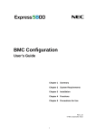
1
NEC Express5800 Series NEC ESMPRO AlertManager User's Guide 7-2006 ONL-4152aN-COMMON-128-99-0606 PROPRIETARY NOTICE AND LIABILITY DISCLAIMER The information disclosed in this document, including all designs and related materials, is the valuable property of NEC, Inc. (NEC) and/or its licensers. NEC and/or its licensers, as appropriate, reserve all patent, copyright and other proprietary rights to this document, including all design, manufacturing, reproduction, use, and sales rights thereto, except to the extent said rights are expressly granted to others. The NEC product(s) discussed in this document are warranted in accordance with the terms of the Warranty Statement accompanying each product. However, actual performance of each such product is dependent upon factors such as system configuration, customer data, and operator control. Since implementation by customers of each product may vary, the suitability of specific product configurations and applications must be determined by the customer and is not warranted by NEC. To allow for design and specification improvements, the information in this document is subject to change at any time, without notice. Reproduction of this document or portions thereof without prior written approval of NEC is prohibited. LAN Manager, MS-DOS, Windows, and Windows NT are registered trademarks of Microsoft, Inc. U.S.A. LANDesk Server Manager is registered trademark of Intel, Inc. U.S.A. Mylex is a registered trademark of LSI Logic Corporations of the U.S. All other product, brand, or trade names used in this publication are the trademarks or registered trademarks of their respective trademark owners. "OpenView" and "HP OpenView" are registered trademarks of HEWLETT PACKARD. "Unicenter TNG" and "CA Unicenter TNG" are registered trademarks of COMPUTER ASSOCIATES. z Contents Chapter1 Installing the Alert Manager .............................................................................1 Chapter2 Using the Alert Manager ...................................................................................3 Report the Alert Function ................................................................................................................ 3 Operation Environment ................................................................................................................... 4 Hardware ..................................................................................................................................... 4 Software ...................................................................................................................................... 4 Operation Overview ........................................................................................................................ 5 Alert Manager Setting ................................................................................................................. 5 Alert Monitoring ......................................................................................................................... 5 Scheduling Function of Alert Report........................................................................................... 6 Report Function of Alert ............................................................................................................. 6 Receive Function of Alert ........................................................................................................... 8 Operation Preparation...................................................................................................................... 9 Setup............................................................................................................................................ 9 Operation ....................................................................................................................................... 18 Overview ................................................................................................................................... 18 Basic Operation of Alert Manager Setting Tool ........................................................................ 18 Setting According to Report Method......................................................................................... 30 Setting According to The Report Receiving Method ................................................................ 53 Setting According to Other Report Receiving Method ............................................................. 55 Save and Restore of Alert Manager Setting .............................................................................. 57 About This Guide The ESMPRO monitors the configuration, failures, and performance of systems across a network. This user's guide is intended for the system administrator and describes ESMPRO capabilities, installation, features, and use. This manual is comprised of the following chapters. Chapter 1, Installing the Alert Manager, explains how to install the Alert Manager. Chapter 2, Using the Alert Manager, explains how to use the Alert Manager. Chapter 1 Installing the Alert Manager Alert Manager software is installed automatically in the Agent and the Manager when Agent software and ESMPRO Manager software are installed. No settings are required to install the Alert Manager. 2 Installing the Alert Manager (This page is intentionally left blank.) Chapter 2 Using the Alert Manager REPORT THE ALERT FUNCTION The function of the Alert Manager is to direct and manage reports on the alerts occurring on the server. The important reporting and receiving methods include: Reporting Method SNMP report to Manager TCP/IP report to Manager Internet Mail Mail (MAPI) Pager call Pop-up message Output to printer Writing to file Command execution Client report Critical log output Receive alert from SMB TCP/IP receive from Agent Operates on the: Agent Agent Agent and Manager Agent and Manager Agent and Manager Agent and Manager Agent and Manager Agent and Manager Agent and Manager Agent Agent Manager Manager Alert Managers in the Agent monitor Windows event logs, Agent's event. Alert Managers in the ESMPRO Manager monitor alert logs supplied by the Agents. 4 Using the Alert Manager OPERATION ENVIRONMENT Hardware the same as the ESMPRO Manager or Agent required. SMTP Server (required for the Internet Mail report) Software Microsoft Exchange Server* (required for the Mail report (with MAPI)) * Exchange Server2000 or later is not supported. Using the Alert Manager 5 OPERATION OVERVIEW Alert Manager consists of the following five major functions: Alert Manager setting Alert monitoring Scheduling function of alert report Report function of alert Receive function of alert Alert Manager Setting Setting tools include the following: – Report setting function - Used for the setting for monitoring objects (event and alert), reporting method, and reporting destination and matches the monitoring object with the reporting destination. – Test report function - Setting contents can be checked by the test report. – The following two kinds of test report methods are provided and both of them can be executed with the ease of pushing a button. y Method of checking whether the destination is correctly set by the report method. y Method of actually simulating the report to the destination related to the monitoring alert by generating the test alert. – Save and restore the Alert Manager setting information including base setting, destination setting and monitor event to a file. Alert Monitoring – Filtering function - extracts the monitor alert under the set conditions. The conditions indicate event source name, server name, and so forth. Conditions to be set depend on the time of event log monitor and alert log monitor. – Suppress function Suppress interval can be specified. 6 Using the Alert Manager Scheduling Function of Alert Report – Report scheduling function: Reportable time periods can be specified. – Retry function: If reporting fails, retry of reporting is done. Retry is specified for each reporting destination with the retry interval and maximum retry time. Report Function of Alert – Manager report(SNMP, TCP/IP) function: This function reports the alert using the SNMP or TCP/IP function. Report contents include a detailed message, support method, and alert type. A report can be issued to the manager under the LAN environment (In-Band report) as well as under the WAN environment (Out-of-Band report) using a Remote Access Service. This function is only available for the Agent. – Internet Mail function: This function uses SMTP protocol to report by Internet Mail. the Mail Server to support SMTP. This function requires Report contents include a detailed message, support method, and alert type. The report contents cannot be selected but the send message can be edited. – Mail (MAPI) function: This function uses the Microsoft Mail function to report by Mail. This function requires an environment under which the post office of Microsoft Mail can be used. Report contents include a detailed message, support method, and alert type. The report contents cannot be selected but the send message can be edited. By associating with the Microsoft information service, reporting destinations such as Internet Mail can be expanded. – Pager call function: This function reports to Numeric Pager through a modem in which the AT commands are available. The report contents include a send message only. An initialization string of a modem can be arbitrarily set. Using the Alert Manager 7 – Pop-up message function: A pop-up message is displayed on the screen when the alert occurs. The report contents include a detailed message, support method, and alert type. A message title can be edited and the report contents can be selected at the time of setting. The pop-up message always displays only one message on the screen. Each message is sequentially displayed with a push of a button. – Printer output function: An alert results in output to the printer when an alert occurs. Output to the network printer is also available. The report contents include a detailed message, support method, and alert type. The message can be edited and the report contents can be selected. – Writing to file function: An alert is written into the text file when an alert occurs. The report contents include a detailed message, support method, and alert type. The message can be edited and the report contents can be selected at the time of setting. – Command execution function: A specified command is executed. Alert Manager can pass the specified command alert information as command line arguments. – Client report function: The report method can issue multicasting messages to the client computer in the same domain. Report contents include a detailed message, support method, and alert type. The report contents can be selected at the time of setting. This function is only available for the Agent. – Critical error logging function: A critical error is written into a critical log. A critical log is the log file in which a critical failure of the system is logged. A message to attract the attention of the user is displayed when the setting is made in order to write the failure into the critical log. This function only supports the NvRAM placed server. – Shutdown, reboot: The system can be shut down and rebooted when the alert occurs. before the system shutdown can be specified. This function is available for the Agent only. A time elapses 8 Using the Alert Manager Receive Function of Alert – Receive Alert from SMB function: This function receives the alert from Server Management Board (SMB). This function is only available for the Manager. – Receive Alert from Agent(TCP/IP) function: This function receives the alert using the TCP/IP function. This function is only available for the Manager. Using the Alert Manager 9 OPERATION PREPARATION Setup To set up the Alert Manager, you must match the event or alert that is to be reported with the report destination and when it is to be reported. 1. Start the Alert Manager setting tool. In the Manager, bring up the Alert Viewer and select Report Settings in the Tools menu. In the Agent, click on the ESMPRO Agent icon in the Control Panel and select Report Settings in the General sheet. 2. Perform Base setting. 3. Create a list of report destinations. 4. Set monitor alerts. 5. For Agent, set monitor events in an event tree. For Manager, set monitor alerts in an alert tree. 6. Associate monitoring alerts with report destinations. 7. Check the setting results by executing a test. 10 Using the Alert Manager Base Setting The base setting consists of the following three items. Setting reporting measures (*1) Setting report reception (*2) Other settings (*1) *1 Set in both an Agent and a Manager. *2 Set in a Manager only. The following can be set on the Base Setting window. – Function valid/invalid status: Green indicates the function is valid and red indicates the function is invalid. Clicking on this bitmap switches valid/invalid indication. Color Green Red State valid invalid Description the function is valid. the function is invalid. Using the Alert Manager 11 – Setting reporting measures: The setting of a reporting measure refers to preparations required for reporting other than the setting of destinations. This section discusses the structure of each reporting measure such as "Setting a modem used for Pager call." However, some reporting measures do not require basic setting. In this case, the effect is displayed on the screen. Some reporting measures require setting of functions other than Alert Manager functions. Manager report (SNMP) requires a structure of the SNMP service of Windows and manager report (TCP/IP Out-of-Band) requires a Remote Access Service structure of Windows. In these cases also, the system indicates on the screen that other settings are required. Bitmap *1 *2 Reporting measures Manager (SNMP) (*1) Manager (TCP/IP In-Band) (*1) Manager (TCP/IP Out-of-Band) (*1) Internet Mail (*2) Mail (*2) Pager (*2) Pop-up Message (*2) Print (*2) Write File (*2) Run Command (*2) Report to Client (*1) Critical error log (*1) *This measures is not indicated in setting dialog. Set in Agent only. Set in both Agent and Manager. NOTE: To report the Alert, make settings by clicking the function status bitmap and change to green. 12 Using the Alert Manager – Setting report reception measures: The setting of a report reception indicates the preparations required for the manager to receive a report. Here, it refers to a structure of each reporting measure such as "setting a mode used for receiving manager reports." Bitmap *1 report reception measures Receive from SMB (*1) Receive from Agent (*1) Set in Manager only. NOTE: To receive the alert, make settings by clicking the function status bitmap and change to green. – Other settings: Other settings refer to the preparations required for setting Alert Manager other than reporting measures and report reception. These settings include the shutdown time setting in Agent. Bitmap *1 report reception measures Shutdown Delay (*1) Set in Agent only. Using the Alert Manager 13 Setting Destinations Destination setting consists of the following four items. Setting destination IDs Setting destination ID groups Selecting a reporting measure and a designation for each destination ID Setting a report schedule for each destination ID NOTE: At installation, set the minimum number of destinations, destinations ID, and ID groups required in the Alert Manager. But these ID settings do not become effective until you create them in “Address Setting” in the [ID Setting] window. Use the Destination Setting window as the base point for the setting. – Setting destination IDs: A destination ID is just like a name in an address book. A name can be assigned freely for each report destination. In the destination ID list, IDs can be added, edited, or deleted. 14 Using the Alert Manager – Setting destination ID groups: A destination ID group can be created by grouping a number of destination IDs. In the destination ID group, ID groups can be added, edited, or deleted. Bitmap Reporting measures destination ID group – Selection of reporting measures and setting destinations: One reporting measure can be selected for each destination ID. To set multiple report IDs for one destination, create multiple destination IDs and group them. When a reporting measure is selected, a destination can be set. The ID cannot be created unless the destination is set. For some reporting measures, the destination can be tested using the designation setting dialogue. – Setting report schedules: A schedule can be set for each destination ID. In the schedule, set a report enabled time zone and report retry. When a destination is set, the report schedule can be set. Setting Monitor Alerts The setting of monitor alerts consists of the following four items. Setting monitor events (*1) Setting monitor alerts (*2) Associating monitor alerts with report destinations (*3) Report test (*1) *1 Set in an Agent only. *2 Set in a Manager only. *3 Set in both an Agent and a Manager. At installation, monitor alerts and reporting measures have been associated. Using the Alert Manager 15 Use tree windows for all the settings. – Setting monitor events (Agent's function): Set for each event that is displayed on the tree. right side of the tree. The setting results are listed on the Click the event to be set and drag it while pressing the right button of the mouse. A tree is displayed on the left side of the Alert Manager screen. switched by pressing the tree selection button. A tree can be Monitoring event trees are organized in the following hierarchical structure. - [Event Log Type] - [Event Source] - [Event ID] - [Report destination ID (or ID group)] Event Log Type Event Source Event ID Report destination ID Bitmap Event log type (System, Security, Application) Event source name of the event to be monitored Event ID of the event to be monitored. Event number is indicated in hexadecimal, like: 0x40002331. The bit map of the event type (error, warning, successful, or information) is displayed on the left side of the event ID. IDs of report destinations are listed. The bit map that indicates the reporting measure is displayed on the left side of the report destination ID. Event type successful information warning error 16 Using the Alert Manager – Setting monitor alerts (Manager's function): Set for each alert to be displayed on the tree. Setting results are listed on the right side of the tree. Click the alert to be set and drag the alert while pressing the right button of the mouse. A tree is displayed on the left side on the Alert Manager screen. switched while pressing the tree selection button. A tree can be A Monitor alert tree is organized in the following hierarchical structure. - [Server name] - [Alert type] - [Report destination ID (or ID group)] - [Report destination ID (or ID group)] Server name Alert type Report destination ID Indicates the server name. Indicates the alert type. (CPU, Fan, and so on) An important degree (Information, Minor, Major, Other) is indicated behind Alert type. IDs of the report destinations are listed. The bit map that indicates the reporting measure is listed on the left side of the report destination ID. – Association of monitor alerts with report destinations: Associate each event displayed on the tree with a report destination. Setting results are displayed in the list on the right side of the tree. For the association, multiple destination IDs and destination group IDs can be set. Click the event to be set and drag it while pressing the right button of the mouse. Using the Alert Manager 17 – Report test: The test enables users to verify whether each event displayed on the tree is notified to the associated destination by generating an event. Execute the test by clicking the event to be set and dragging it while pressing the right button of the mouse. – Displaying information on monitor events and alerts: Information on the items selected from the tree is displayed in list control on the right side on the Alert Manager tree screen. 18 Using the Alert Manager OPERATION Overview This section gives an explanation of practical operation for Alert Manager. Basic operation of setting tool Setting according to report method Setting according to report receiving method Other settings Basic Operation of Alert Manager Setting Tool Base Setting Base Setting window This window is used to make the basic setting of Report methods, report receiving methods, and others in Alert Manager. Select Base Setting in a Setting menu or a button of the toolbar to make the setting. Base setting of report method (Report) Using the Alert Manager 19 – Report method list: Bitmaps indicating report methods, report valid/invalid bitmaps are displayed. – Report method bitmaps: This bitmap indicates the report method. – Report valid/invalid bitmap: Green indicates the report valid and red indicates the report invalid. Clicking on this bitmap switches valid/invalid indication. – Report method description: Selecting the report method displays description for the report method. – Configure button: This button makes the base setting of the selected report method. However, the Configure button is not available in some report methods. Base setting of report receiving method (Receive) – Report receiving method list: Bitmaps indicating report receiving methods and report receiving valid/invalid bitmaps are displayed. – Report receiving method bitmap: This bitmap indicates the report receiving method. – Receiving valid/invalid bitmap: Green indicates receiving valid and red indicates receiving invalid. Clicking on this bitmap switches valid/invalid indication. 20 Using the Alert Manager – Report receiving method description: Selecting the report receiving method displays the description for the report receiving method. – Configure button: This button makes the base setting of the selected report receiving method. However the Configure button is not available in some report receiving methods. Other base setting (Other) – Other setting list: Bitmaps indicating other settings are displayed. – Setting bitmap: This bitmap indicates setting contents. – Setting valid/invalid bitmap: Green indicates setting valid and red indicates setting invalid. Clicking on this bitmap switches valid/invalid indication. – Setting item description: Selecting the setting item displays the description for the setting item. – Configure button: This button makes the setting of the selected setting item. Using the Alert Manager 21 Destination Setting Destination Setting dialog The setting is made by selecting Destination Setting of the Setting menu or a button of the toolbar. ID and Group set in the address book are listed. – ID list: ID : ID names are displayed. Method : Report methods are displayed. Address : Addresses are displayed. – Group list: Group : Group names are displayed. ID : An ID list included in the group is displayed. – Add ID button: An ID is added. Pressing this button displays an ID Setting dialog box. – Modify ID button: This is used to modify the report destination for the ID selected from the ID list. Pressing this button displays an ID Setting dialog box. 22 Using the Alert Manager – Delete ID button: An ID selected from the ID list is deleted. – Add Group button: Group is added. Pressing this button displays a Group Setting dialog box. – Modify Group button: IDs to be added to Group are modified on the Group selected from the Group list. Pressing this button displays a Group Setting dialog box. – Delete Group button: Group selected from the Group list is deleted. – Close button: Destination Setting dialog closes. ID Setting window – ID: ID names are displayed. – Method: Report methods are displayed. – Address: Report destinations are displayed. Using the Alert Manager 23 How to Make Setting For additions: 1. Enter an ID name. 2. Select a reporting method in the Method field, such as Mail, Pager, or Print. 3. If the Address button is available, select it and set the address. 4. Click on Schedule to set a schedule. 5. Click on Close. For modification: 1. If necessary, press the Address and Schedule button to make the report destination setting and schedule setting. 2. Click on OK. NOTE: In the case of modification, ID and Method items are indicated with light color and no setting can be made. Group Setting window – Group Name: Group names are displayed. – ID: An ID list is displayed. IDs included in the Group Member are not displayed. – Group Member: An ID set as a member of a group is displayed. 24 Using the Alert Manager – Add button: IDs selected from the ID list are moved to the Group Member list. – Remove button: An ID selected from the Group Member list is moved to the ID list. How to Make Setting For additions: 1. Enter a group name. 2. Select the ID to include in the group member from the ID list. 3. Click on Add to move the selected ID to Group Member. 4. To delete the ID from the group member, delete it from the Group Member list and click on Remove. 5. Click on OK. NOTE: For modification, Group Name is indicated with light color and no modification can be made. Schedule window – Retry Interval: Set the port number in the range of 1 to 30 minutes. – Whole Retry Time: Set the maximum retry time in the range of 0 to 240 hours. – Reporting Time Table: Set the reportable time periods. Using the Alert Manager 25 Addition of Monitoring Object Event The setting is made by selecting Monitor Event Setting in the menu displayed by dragging the right mouse button on a main window. Select Monitor Event window – Source: A source name is selected. – Event ID List: Event IDs of the selected Source are listed. – Monitor Event: Event IDs of the report object are listed. How to Make Setting 1. Select Source. 2. Select the event ID you want make it a report object from an Event ID list. 3. Pressing the Add button moves the selected event ID to the Monitor Event list. 4. To delete a report object event, select the event ID from the Monitor Event list and press the Remove button to delete it. 5. Press the OK button. NOTE: If dialog is opened from the event source name of the tree, Source is indicated with light color and no selection can be made. 26 Using the Alert Manager Addition of Monitoring Object Alert The setting is made by selecting Monitor Event Setting from the menu displayed by dragging the right mouse button on a main window. Select Monitor Alert window – Server Name: A server name is selected. – Alert Type List: Alert Type of the selected server name is listed. An important degree (Information, Minor, Major, Other) is indicated behind Alert type. – Monitor Alert Type: Alert Type to be reported is listed. To Make a Setting 1. Select the Server Name. 2. Select the Alert Type to be reported from the list. 3. Clicking on Add moves selected Alert Type to the Monitor Alert list. 4. To delete the event to be reported, select Alert Type from the Monitor Alert list and click on Remove to delete it. 5. Click on OK. NOTE: If the window is opened by the Server name, Server Name is indicated with light color and no selection can be made. Using the Alert Manager 27 Monitor Event Setting The setting is made by selecting Monitor Event Setting from a menu displayed by dragging the right mouse button on a main window. Monitor Event Setting window – Source: Source names are displayed. – Event ID: Event IDs are displayed. – Event Message: Messages are displayed. – Trap Name: Enter a trap name. – Operation After Notification: Select an action after notification. – Recovery Action: Set how to handle. – Suppress button: This button makes the setting of the report suppress. NOTE: "Default" is set up in Alert Type of a new monitoring event which a user registered. 28 Using the Alert Manager Suppress window – Suppress Interval: Mark this check box to suppress report of the same event during the Suppress Interval. – Suppress a report of the same event for [ ] minutes: Set the Suppress Interval in the range of 0 to 1440. If you set 0 minute, no report is suppressed and all events are reported. – Number of occurred event: Mark this check box to report when same event occurs specified times per specified interval. – Report when same event occurs [ ] times per [ ] minutes: Set the Interval in the range of 1 to 9999 and Times in the range of 1 to 99. Monitor Alert Setting Monitoring the alert setting is not provided. Using the Alert Manager 29 Destination Association Setting The setting is made by selecting Link Destination from a menu displayed by dragging the right mouse button on a main window. Link Destination window – Source: Source names are displayed. – Event ID: Event IDs are displayed. – Event Message: Messages are displayed. – Destination ID List: An ID list is displayed. – Report To: A report object ID list is displayed. – Add button: An ID selected from the Destination ID list is moved to Report To. 30 Using the Alert Manager – Remove button: IDs selected from the Report To list are moved to the Destination ID list. – ID list: Information for IDs selected from the Destination ID and Report To lists is displayed. – Group list: Information for IDs selected from the Destination ID and Report To lists is displayed. To Make a Setting 1. Select the ID to be reported from the Destination ID list. 2. Clicking on Add moves the ID to the Report To list. 3. To delete IDs from report objects, select the ID from Report To list and click on Remove to move the ID to the Destination ID list. 4. Click on OK. Setting According to Report Method To set the base setting Use the [Report] property sheet of the [Base Setting] dialog to select the method from the list and make the setting in the dialog displayed by pressing the [Configure...] button. To report the Alert, make settings by clicking the function status bitmap and change to green. To set destination setting Select the method from the method list at the time of ID setting in the [Destination Setting] dialog and make the setting in the dialog displayed by pressing the [Address...] button. Manager Report (SNMP) No item is provided to set in Alert Manager for the base setting and destination setting. Make the setting of the SNMP service in Control panel [Network] of Windows. Set also a destination of the remote manager using the SNMP service. Manager Report (TCP/IP In-Band) No base setting is required. Make the following setting for destination setting. Using the Alert Manager 31 [Manager (TCP/IP In-Band)] dialog – [IP address (or host name)]: An IP address (or host name) of the remote Manager is set. Make sure to specify the IP address of the remote Manager. NOTE: If the remote Manager to be set has already been specified as the trap destination of the SNMP service, release the trap destination setting of the SNMP service. NOTE: Exercise the care to avoid duplicate setting of the same IP address (or host name) for the trap destination of the SNMP service after this setting. If duplicate setting is made, more than one alert will be reported. – [Port number]: The port number used for the communication between sockets can be set. For this number, the same value must be set to the Agent and remote Manager (the default value is 31134 for both Agent and remote Manager). Do not change the value as long as the default value works. 32 Using the Alert Manager IMPORTANT: If the default value does not work, set the port number in the range of 6001 to 65535. Clicking the [Default] button resets the number to the default value (31134). If a modification is made, be sure to also modify the setting for the remote manager. This modification is made in the setting of TCP/IP receive in the [Receive from Agent (TCP/IP) Setting] dialog of the base setting by executing the Alert Manager setting tool on the server in which Manager is installed. – [OK]: Set information is added and this dialog box closes. – [Cancel]: This dialog box closes with no set information added. – [Test]: For the test report, press this button. The test result can be checked by a message. Manager Report (TCP/IP Out-of-Band) No base setting is required. Before setting the destination, make configuration of the Remote Access Service. Additionally set an entry of the Remote Access Service. If the entry of the Remote Access Service is not set, no destination setting can be made. For the destination settings, make the following settings. Using the Alert Manager [Manager (TCP/IP Out-of-Band)] dialog – [IP address (or host name)]: An IP address (or host name) of the remote Manager is set. Be sure to specify the IP address of the remote Manager. NOTE: If the remote Manager to be set has been already set as the trap destination of the SNMP service, release the setting of the SNMP service. Exercise care to avoid duplicate settings of the same IP address (or host name) for the trap destination of the SNMP service after this setting. If duplicate setting is made, more than one alert will be reported. – [Entry to Use]: Select a Remote Access Service entry from the list. – [User]: To gain the Remote Access Service, enter a user name of the selected entry. – [Password]: To gain the Remote Access Service, enter a password of the selected entry. 33 34 Using the Alert Manager – [Port number]: The port number used for the communication between sockets can be set. For this number, the same value must be set to the Agent and remote Manager (the default value is 31134 for both Agent and remote Manager). Do not change the value as long as the default value works. IMPORTANT: If the default value does not work, set the port number in the range of 6001 to 65535. Clicking the [Default] button resets the number to the default value (31134). If a modification is made, be sure to also modify the setting for the remote manager. This modification is made in the setting of TCP/IP receive in the [Receive from Agent (TCP/IP) Setting] dialog of the base setting by executing the Alert Manager setting tool on the server in which Manager is installed. – [OK]: Set information is added and this dialog box closes. – [Cancel]: This dialog box closes with no set information added. – [Test]: For the test report, press this button. The test result can be checked by a message. Using the Alert Manager 35 Internet Mail For the base setting, make the following settings. [Internet Mail Base Setting] dialog – [Mail Server (SMTP)]: Specify either an IP address or the name the Internet Mail Server will be using. (This Mail Server needs to support SMTP.) – [E-mail address]: Type in the E-mail address for your mail account in the form user@domain. – [OK]: Set information is added and this dialog box closes. – [Cancel]: This dialog box closes with no set information added. 36 Using the Alert Manager For the destination settings, make the following settings. [Internet Mail Destination Setting] dialog – [To]: Type in the E-mail address (To:) in the form user@domain. Be sure to divide it with , (comma) when you specify plural addresses (e.g. [email protected], [email protected]). – [Subject]: Enter a title of the mail. – [Message Head]: To send a message, enter information. message header and alert information. Message contents of actual mail consist of this – [Enable]: Mark this check box when you send mail through Remote Access Service (RAS). NOTE: Before setting the destination, configure the Remote Access Service. Additionally, set an entry for the Remote Access Service. If the entry for the Remote Access Service is not set, this check box cannot be marked. – [Entry to Use]: Select a Remote Access Service entry from the list. Using the Alert Manager – [User]: Enter RAS user name. – [Password]: Enter RAS user's password. – [Base Setting]: To open the Internet Mail Base Setting dialog, press this button. – [OK]: Set information is added and this dialog box closes. – [Cancel]: This dialog box closes with no set information added. – [Test]: For the test report, press this button. The test result can be checked by a message. 37 38 Using the Alert Manager Mail (MAPI) No base setting is provided. Before setting the destination, sign in must be done to the post office (Mail server) of MS Mail. Displayed dialog for sign in is different for MS Mail, MS Exchange. [Sign In] dialog (For MS Mail) – [Mail Box]: Enter a mail box name. Once this has been set, the name is displayed. – [Password]: Enter a password. [Sign In] dialog (For MS Exchange) – [Profile]: Enter a profile name. Using the Alert Manager 39 For the destination setting, make the following setting: [Mail Setting] dialog – [To], [Cc]: A destination of a mail set by pressing [Address...] button is displayed. Information cannot be entered directly here. – [Address...]: [Address] dialog (Address Book of Mail) is displayed. Set the mail address in this dialog. Previously set the destination to Address Book by Mail. – [Subject]: Enter a title of the mail. – [Message Head]: To send a message, enter information. Message contents of actual mail consist of this message header, alert information, and attached file in this sequence. – [Attach File]: To attach the file, press the [Attach] button to select the file. Only one file can be attached. The file is added to the end of the message. Information cannot be directly entered to the edit box. – [Attach...]: The attached file can be selected from the browser. 40 Using the Alert Manager – [Detach]: File attach is canceled. – [OK]: Set information is added and this dialog box closes. – [Cancel]: This dialog box closes with no set information added. – [Test]: For the test report, press this button. The test result can be checked by a message. NOTES: To report the alert by Mail, log on with the user name belonging to the Administrator who created a profile on the Alert Manager Main Service. This is a restriction of Microsoft Corporation. [How to setup] 1. Stop the Alert Manager Main Service in the [Services] Control Panel. 2. Push the [Startup...] button. 3. Push the [This Account] radio button and enter the account (of the user who created the profile), password and confirm the password by entering it again. Then push the [OK] button. 4. Start the Alert Manager Main Service. When reporting the alert by Mail, do not run "Inbox" (EXCHNG32.EXE). Using the Alert Manager [Address] dialog (On MS Mail) [Address] dialog (On Messaging) 41 42 Using the Alert Manager Pager Call For the base setting, make the following settings. [Pager Setting] dialog (Base Setting) – [Serial port]: Select the serial port to which a modem is to be used for the Pager call. If no serial port exists, no base setting can be made. – [Modem initialization string 1]: An initialization command to recall factory configuration as active configuration can be set. At the time of installation, the following setting is made. AT&F – [Modem initialization string 2]: An initialization command of a modem used for the Pager call can be set. At the time of installation, the following setting is made. ATX3E0Q0V1 – [OK]: Set information is added and this dialog box closes. – [Cancel]: This dialog box closes with no set information added. Using the Alert Manager 43 For the destination setting, make the following setting. [Pager Setting] dialog (Destination Setting) – [Phone number]: Enter a telephone number of the Pager service provider. Numeric characters (0 to 9) can be entered and '-' can be used as a separator. <Example> To specify telephone number "012-345-6789" "012-345-6789" or "0123456789" <Example> is 0) To call an outside line from an interphone, (in this example, dial number "0,012-345-6789" <Explanation> "0" 0 is dialed. "," A constant pause is put. Telephone number "012-345-6789" is dialed. Make sure to specify a telephone number. – [Message]: A message to be sent to a pager is specified. Make the setting as follows: <Example> To set a message "01234" ",,,,,01234,,,#" <Explanation> ",,,,," A send standby time is set (waits until connection and announcement are made). The pause can be adjusted according to the number of ","(pause command). 44 Using the Alert Manager The value (second) which can be set for "," depends on the setting of the "S8" register (pause time) of the used modem. For more information, see the guide of the modem. "01234" Sending message ",,," Termination standby time is set (a sending termination time is adjusted). "#" This is the termination symbol to informing of the message termination. termination symbol varies by the used pager. A NOTE: Depending on the pager, characters to be displayed vary. For more information, see the guide for the pager. If duplicate setting is made, more than one alert will be reported. – [OK]: Set information is added and this dialog box closes. – [Cancel]: This dialog box closes with no set information added. – [Test]: Pressing the [Test] button runs a test of sending to the set pager. The result is displayed in a message box. If an error occurs, make the setting again according to the message contents. Using the Alert Manager 45 Pop-up Message No base setting is required. For the destination setting, make the following setting: [Pop-up Message Setting] dialog box is used to set and modify the display of a pop-up message of failure information. [Pop-up Message Setting] dialog – [Title]: A title of a pop-up message is written. – [Computer Name]: To display a computer name, mark this check box. – [Product Name]: To display a product name, mark this check box. – [Date]: To display a date, mark this check box. – [Time]: To display a time, mark this check box. – [Event Source]: To display a source name, mark this check box. – [Event ID]: To display an event ID mark this check box. – [OK]: Set information is added and this dialog box closes. – [Cancel]: This dialog box closes with no set information added. – [Test]: For the test report, press this button. 46 Using the Alert Manager Printer Output No base setting is required. For destination setting, make the following setting. [Print Setting] dialog is used to set and modify the printer output of failure information. [Print Setting] dialog – [Printer Name]: A printer name is displayed in this column. – [Printer...]: To modify a printer, press this button. – [Header]: A header comment to display with failure information is written. – [Computer Name]: To display a computer name, mark this check box. – [Product Name]: To display a product name, mark this check box. – [Date]: To display a date, mark this check box. Using the Alert Manager – [Time]: To display a time, mark this check box. – [Event Source]: To display a source name, mark this check box. – [Event ID]: To display an event ID, mark this check box. – [Event Type]: To display an event type, mark this check box. – [Event Message]: To display details, mark this check box. – [Recovery Action]: To display how to handle, mark this check box. – [Alert Type]: To display an alert type, mark this check box. – [Footer]: A footer comment displaying with failure information is written. – [OK]: Set information is added and this dialog box closes. – [Cancel]: This dialog box closes with no set information added. – [Test]: For the test report, press this button. 47 48 Using the Alert Manager Writing to File Base setting is not required. For the destination setting, make the following setting: [Write File Setting] dialog is used to set and modify the settings for writing the failure information to a file. [Write File Setting] dialog – [File Name]: A file name writing information is displayed. – [File...]: To Add or modify a file name press this button. – [Header]: A header comment displaying with the failure information is written. – [Computer Name]: To display a computer name, mark this check box. – [Product Name]: To display a product name, mark this check box. – [Date]: To display a date, mark this check box. Using the Alert Manager – [Time]: To display a time, mark this check box. – [Event Source]: To display a source name, mark this check box. – [Event ID]: To display an event ID, mark this check box. – [Event Type]: To display an event type, mark this check box. – [Event Message]: To display details, mark this check box. – [Recovery Action]: To display how to handle, mark this check box. – [Alert Type]: To display an alert type, mark this check box. – [OK]: Set information is added and this dialog box closes. – [Cancel]: This dialog box closes with no set information added. – [Test]: For the test report, press this button. 49 50 Using the Alert Manager Command Execution No base setting is required. For the destination setting, make the following setting: [Run Command Setting] dialog – [Command Line]: A file name to write information is displayed. The information can be directly entered into the edit box. The following specification is available for the command argument. – %a Alert type – %i Event ID – %n Trap name – %r Server name – %s Event source name – %t Alert occurrence time Example: ap.exe %s %i An event source name is passed to ap.exe as the primary argument and an event ID as the secondary argument. – [Browse]: To select a command from a browser, press this button. – [OK]: Set information is added and this dialog box closes. – [Cancel]: This dialog box closes with no set information added. – [Test]: For the test report, press this button. Using the Alert Manager 51 Client Report No base setting is required. Refer to the following for the explanation about Destination setting. [Report to Clients Setting] dialog – [Report to All]: Select this if you want to report to all the computers. – [Report to Select]: Select this if you want to report to specific computers in Domain Group. – [Computer List]: The computer is not reported. – [Selected Computer]: The computer is reported. – [Add]: Move selected computers from [Computer List] to [Selected Computer]. – [Delete]: Move selected computers from [Selected Computer] to [Computer List]. – [OK]: This dialog box closes with no set information added. 52 Using the Alert Manager – [Cancel]: This dialog box closes with no set information added. – [Alert Item]: For selecting report items, press this button. – [Test]: For the test report, press this button. [Alert Item Setting] dialog – [Computer Name]: Check this to display a computer name. – [Date]: Click this to display a date. – [Time]: Click this to display a time. – [Event Source]: Click this to display a source name. – [Event ID]: Click this to display an event ID. – [OK]: Set information is added and this dialog box closes. – [Cancel]: This dialog box closes with no set information added. Using the Alert Manager 53 Setting According to The Report Receiving Method The [Receive] property sheet of the [Base Setting] dialog is used to select a method from a list and the setting is made in the dialog displayed by pressing the [Configure] button. To report the Alert, make settings by clicking the function status bitmap and change to green. Setting of Alert Receiving from SMB Setting is made to receive a report from Server Management Board (SMB). Make the following setting: [Receive from SMB Setting] dialog is used to set and modify the receiving function of automatic reports of SMB. [Receive from SMB Setting] dialog – [Serial port]: To receive automatic reports from SMB, select the serial port used for receiving automatic reports from SMB. – [OK]: Set information is added and this dialog box closes. – [Cancel]: This dialog box closes with no set information added. 54 Using the Alert Manager Setting of Alert Receiving from Agent (TCP/IP) Make the setting as follows: [Receive from Agent (TCP/IP) Setting] dialog is used to set and modify a socket receive. [Receive from Agent (TCP/IP) Setting] dialog – [Port Number]: Enter a port number used for socket receiving. This is not optional. – [Default]: To put the port number back to a default, press this button. For this number, the same value must be set to the Agent and Manager (a default value is 31134 for both of Agent and remote Manager). Do not change the value as long as the default value works. – [OK]: Set information is added and this dialog closes. – [Cancel]: This dialog closes with no set information added. Using the Alert Manager 55 Setting According to Other Report Receiving Method Select the setting method from a list in the [Other] property sheet of [Base Setting] dialog and make the setting in the dialog displayed by pressing the [Configure] button. Setting of Time Elapses Before Shut Down [Shutdown Delay Setting] dialog – [Shutdown Delay]: Enter the time that elapses before shut down. The setting is available in a range of 0 to 60. Set contents become available immediately after the setting is made. – [Vanish 'Cancel' button]: To vanish 'Cancel' button that shut down dialog, mark this check box. – [Report to Manager, shutting down or rebooting]: To report to Manager when shut down or rebooting was active, mark this check box. – [Report to Manager, canceling shutting or rebooting]: To report to Manager when shut down or rebooting was canceled, mark this check box. – [OK]: Set information is added and this dialog box closes. – [Cancel]: This dialog box closes with no set information added. 56 Using the Alert Manager NOTE: If this function status is Red, the server never shut down/reboot even if a critical event or the shutting down request from the remote Manager has occurred. IMPORTANT: If these events occur, the server will shut down. 1. Requested system shutdown from Manager. 2. The temperature exceeds the upper threshold. 3. The temperature is below the lower threshold. 4. Fan unit is malfunctioning. 5. Power unit is malfunctioning. 6. Expansion Chassis major alert reported. 7. The voltage exceeds the upper limit. 8. The voltage below the lower limit. 9. DC Voltage Alert reported. 10. CPU thermal trip occurred. 11. HDD temperature is in error status. Using the Alert Manager 57 Save and Restore of Alert Manager Setting Make the setting in the dialog displayed by pressing the [Save Alert Manager Setting] or [Restore Alert Manager Setting] or [Save Monitor Event] of [Options] menu. Setting of "Save Alert Manager Setting" You can save the Alert Manager setting information including base setting, destination setting and monitor event to a file. [Save Alert Manager Setting] dialog – [Computer Name]: Computer name is displayed. – [Description]: When you want to add description to the file, input the description under 40 bytes of characters. This description is displayed in the [Restore Alert Manager Setting] dialog. – [File Name]: A file name you selected is displayed. – [File...]: To modify a file name press this button. – [Save]: To Save the Alert Manager setting information to the file. How to save the Alert Manager setting information 1. Press the [File…] button to select the drive and folder where you want to save the setting information and enter a file name. 2. Input the description if necessary. 3. Press the [Save...] button. 4. Click on OK. 58 Using the Alert Manager Setting of "Restore Alert Manager Setting" You can restore the Alert Manager setting information from the file to your system. The file must be the following. 1. The file which is saved in the Alert Manager of the same version. 2. The file which is saved on the same product environment. [Restore Alert Manager Setting] dialog – [Computer Name]: Computer name is displayed. – [Description]: The description which is inputted in the [Save Alert Manager Setting] dialog is displayed. – [File Name]: A file name you selected is displayed. – [Date]: The saving date of the file is displayed. – [OK]: To restore the Alert Manager setting press this button. How to restore the setting information 1. Select the Options menu Restore Alert Manager Setting... 2. Select the drive, folder and correct file name. 3. Click on OK. NOTE: If you restore the Alert Manager setting information, all your setting information will be deleted. Using the Alert Manager 59 Setting of "Save Monitor Event" You can save the monitor event information of the Alert Manager (including monitoring event, monitoring alert, monitoring indication, trap name, event message, destination etc.) to CSV file. The monitor event which can be selected is different according to the installed product (ESMPRO Agent, ESMPRO Manager etc.). [Save Monitor Event] dialog – [EventLog]: To save a monitor event information of the Event Log in a CSV file, mark this check box. – [Agent Events]: To save a monitor event information of the Agent Events in a CSV file, mark this check box. – [AlertLog]: To save a monitor event information of the AlertLog in a CSV file, mark this check box. – [File Name]: Enter a CSV file name to save the monitor event information. Please type the full path of a CSV file into the edit box. Or, select a file from browser appears by pressing [Browse...] button. 60 Using the Alert Manager (This page is intentionally left blank.)