1
TPC-2012
User Manual
TPC-2012 User Manual
July 2007
372052B-01
Support
Worldwide Technical Support and Product Information
ni.com
National Instruments Corporate Headquarters
11500 North Mopac Expressway
Austin, Texas 78759-3504
USA Tel: 512 683 0100
Worldwide Offices
Australia 1800 300 800, Austria 43 662 457990-0, Belgium 32 (0) 2 757 0020, Brazil 55 11 3262 3599,
Canada 800 433 3488, China 86 21 5050 9800, Czech Republic 420 224 235 774, Denmark 45 45 76 26 00,
Finland 358 (0) 9 725 72511, France 01 57 66 24 24, Germany 49 89 7413130, India 91 80 41190000,
Israel 972 3 6393737, Italy 39 02 413091, Japan 81 3 5472 2970, Korea 82 02 3451 3400,
Lebanon 961 (0) 1 33 28 28, Malaysia 1800 887710, Mexico 01 800 010 0793, Netherlands 31 (0) 348 433 466,
New Zealand 0800 553 322, Norway 47 (0) 66 90 76 60, Poland 48 22 3390150, Portugal 351 210 311 210,
Russia 7 495 783 6851, Singapore 1800 226 5886, Slovenia 386 3 425 42 00, South Africa 27 0 11 805 8197,
Spain 34 91 640 0085, Sweden 46 (0) 8 587 895 00, Switzerland 41 56 2005151, Taiwan 886 02 2377 2222,
Thailand 662 278 6777, Turkey 90 212 279 3031, United Kingdom 44 (0) 1635 523545
For further support information, refer to the Technical Support and Professional Services appendix. To comment
on National Instruments documentation, refer to the National Instruments Web site at ni.com/info and enter
the info code feedback.
© 2006–2007 National Instruments Corporation. All rights reserved.
Important Information
Warranty
The TPC-2012 is warranted against defects in materials and workmanship for a period of one year from the date of shipment, as evidenced by
receipts or other documentation. National Instruments will, at its option, repair or replace equipment that proves to be defective during the
warranty period. This warranty includes parts and labor.
The media on which you receive National Instruments software are warranted not to fail to execute programming instructions, due to defects in
materials and workmanship, for a period of 90 days from date of shipment, as evidenced by receipts or other documentation. National Instruments
will, at its option, repair or replace software media that do not execute programming instructions if National Instruments receives notice of such defects
during the warranty period. National Instruments does not warrant that the operation of the software shall be uninterrupted or error free.
A Return Material Authorization (RMA) number must be obtained from the factory and clearly marked on the outside of the package before any
equipment will be accepted for warranty work. National Instruments will pay the shipping costs of returning to the owner parts which are covered by
warranty.
National Instruments believes that the information in this document is accurate. The document has been carefully reviewed for technical accuracy. In
the event that technical or typographical errors exist, National Instruments reserves the right to make changes to subsequent editions of this document
without prior notice to holders of this edition. The reader should consult National Instruments if errors are suspected. In no event shall National
Instruments be liable for any damages arising out of or related to this document or the information contained in it.
EXCEPT AS SPECIFIED HEREIN, NATIONAL INSTRUMENTS MAKES NO WARRANTIES, EXPRESS OR IMPLIED, AND SPECIFICALLY DISCLAIMS ANY WARRANTY OF
MERCHANTABILITY OR FITNESS FOR A PARTICULAR PURPOSE. CUSTOMER’S RIGHT TO RECOVER DAMAGES CAUSED BY FAULT OR NEGLIGENCE ON THE PART OF NATIONAL
INSTRUMENTS SHALL BE LIMITED TO THE AMOUNT THERETOFORE PAID BY THE CUSTOMER. NATIONAL INSTRUMENTS WILL NOT BE LIABLE FOR DAMAGES RESULTING
FROM LOSS OF DATA, PROFITS, USE OF PRODUCTS, OR INCIDENTAL OR CONSEQUENTIAL DAMAGES, EVEN IF ADVISED OF THE POSSIBILITY THEREOF. This limitation of
the liability of National Instruments will apply regardless of the form of action, whether in contract or tort, including negligence. Any action against
National Instruments must be brought within one year after the cause of action accrues. National Instruments shall not be liable for any delay in
performance due to causes beyond its reasonable control. The warranty provided herein does not cover damages, defects, malfunctions, or service
failures caused by owner’s failure to follow the National Instruments installation, operation, or maintenance instructions; owner’s modification of the
product; owner’s abuse, misuse, or negligent acts; and power failure or surges, fire, flood, accident, actions of third parties, or other events outside
reasonable control.
Copyright
Under the copyright laws, this publication may not be reproduced or transmitted in any form, electronic or mechanical, including photocopying,
recording, storing in an information retrieval system, or translating, in whole or in part, without the prior written consent of National
Instruments Corporation.
National Instruments respects the intellectual property of others, and we ask our users to do the same. NI software is protected by copyright and other
intellectual property laws. Where NI software may be used to reproduce software or other materials belonging to others, you may use NI software only
to reproduce materials that you may reproduce in accordance with the terms of any applicable license or other legal restriction.
Trademarks
National Instruments, NI, ni.com, and LabVIEW are trademarks of National Instruments Corporation. Refer to the Terms of Use section
on ni.com/legal for more information about National Instruments trademarks.
Other product and company names mentioned herein are trademarks or trade names of their respective companies.
Members of the National Instruments Alliance Partner Program are business entities independent from National Instruments and have no agency,
partnership, or joint-venture relationship with National Instruments.
Patents
For patents covering National Instruments products, refer to the appropriate location: Help»Patents in your software, the patents.txt file
on your CD, or ni.com/patents.
WARNING REGARDING USE OF NATIONAL INSTRUMENTS PRODUCTS
(1) NATIONAL INSTRUMENTS PRODUCTS ARE NOT DESIGNED WITH COMPONENTS AND TESTING FOR A LEVEL OF
RELIABILITY SUITABLE FOR USE IN OR IN CONNECTION WITH SURGICAL IMPLANTS OR AS CRITICAL COMPONENTS IN
ANY LIFE SUPPORT SYSTEMS WHOSE FAILURE TO PERFORM CAN REASONABLY BE EXPECTED TO CAUSE SIGNIFICANT
INJURY TO A HUMAN.
(2) IN ANY APPLICATION, INCLUDING THE ABOVE, RELIABILITY OF OPERATION OF THE SOFTWARE PRODUCTS CAN BE
IMPAIRED BY ADVERSE FACTORS, INCLUDING BUT NOT LIMITED TO FLUCTUATIONS IN ELECTRICAL POWER SUPPLY,
COMPUTER HARDWARE MALFUNCTIONS, COMPUTER OPERATING SYSTEM SOFTWARE FITNESS, FITNESS OF COMPILERS
AND DEVELOPMENT SOFTWARE USED TO DEVELOP AN APPLICATION, INSTALLATION ERRORS, SOFTWARE AND HARDWARE
COMPATIBILITY PROBLEMS, MALFUNCTIONS OR FAILURES OF ELECTRONIC MONITORING OR CONTROL DEVICES,
TRANSIENT FAILURES OF ELECTRONIC SYSTEMS (HARDWARE AND/OR SOFTWARE), UNANTICIPATED USES OR MISUSES, OR
ERRORS ON THE PART OF THE USER OR APPLICATIONS DESIGNER (ADVERSE FACTORS SUCH AS THESE ARE HEREAFTER
COLLECTIVELY TERMED “SYSTEM FAILURES”). ANY APPLICATION WHERE A SYSTEM FAILURE WOULD CREATE A RISK OF
HARM TO PROPERTY OR PERSONS (INCLUDING THE RISK OF BODILY INJURY AND DEATH) SHOULD NOT BE RELIANT SOLELY
UPON ONE FORM OF ELECTRONIC SYSTEM DUE TO THE RISK OF SYSTEM FAILURE. TO AVOID DAMAGE, INJURY, OR DEATH,
THE USER OR APPLICATION DESIGNER MUST TAKE REASONABLY PRUDENT STEPS TO PROTECT AGAINST SYSTEM FAILURES,
INCLUDING BUT NOT LIMITED TO BACK-UP OR SHUT DOWN MECHANISMS. BECAUSE EACH END-USER SYSTEM IS
CUSTOMIZED AND DIFFERS FROM NATIONAL INSTRUMENTS' TESTING PLATFORMS AND BECAUSE A USER OR APPLICATION
DESIGNER MAY USE NATIONAL INSTRUMENTS PRODUCTS IN COMBINATION WITH OTHER PRODUCTS IN A MANNER NOT
EVALUATED OR CONTEMPLATED BY NATIONAL INSTRUMENTS, THE USER OR APPLICATION DESIGNER IS ULTIMATELY
RESPONSIBLE FOR VERIFYING AND VALIDATING THE SUITABILITY OF NATIONAL INSTRUMENTS PRODUCTS WHENEVER
NATIONAL INSTRUMENTS PRODUCTS ARE INCORPORATED IN A SYSTEM OR APPLICATION, INCLUDING, WITHOUT
LIMITATION, THE APPROPRIATE DESIGN, PROCESS AND SAFETY LEVEL OF SUCH SYSTEM OR APPLICATION.
Compliance
Compliance with FCC/Canada Radio Frequency Interference
Regulations
Determining FCC Class
The Federal Communications Commission (FCC) has rules to protect wireless communications from interference. The FCC
places digital electronics into two classes. These classes are known as Class A (for use in industrial-commercial locations only)
or Class B (for use in residential or commercial locations). All National Instruments (NI) products are FCC Class A products.
Depending on where it is operated, this Class A product could be subject to restrictions in the FCC rules. (In Canada, the
Department of Communications (DOC), of Industry Canada, regulates wireless interference in much the same way.) Digital
electronics emit weak signals during normal operation that can affect radio, television, or other wireless products.
All Class A products display a simple warning statement of one paragraph in length regarding interference and undesired
operation. The FCC rules have restrictions regarding the locations where FCC Class A products can be operated.
Consult the FCC Web site at www.fcc.gov for more information.
FCC/DOC Warnings
This equipment generates and uses radio frequency energy and, if not installed and used in strict accordance with the instructions
in this manual and the CE marking Declaration of Conformity*, may cause interference to radio and television reception.
Classification requirements are the same for the Federal Communications Commission (FCC) and the Canadian Department
of Communications (DOC).
Changes or modifications not expressly approved by NI could void the user’s authority to operate the equipment under the
FCC Rules.
Class A
Federal Communications Commission
This equipment has been tested and found to comply with the limits for a Class A digital device, pursuant to part 15 of the FCC
Rules. These limits are designed to provide reasonable protection against harmful interference when the equipment is operated
in a commercial environment. This equipment generates, uses, and can radiate radio frequency energy and, if not installed and
used in accordance with the instruction manual, may cause harmful interference to radio communications. Operation of this
equipment in a residential area is likely to cause harmful interference in which case the user is required to correct the interference
at their own expense.
Canadian Department of Communications
This Class A digital apparatus meets all requirements of the Canadian Interference-Causing Equipment Regulations.
Cet appareil numérique de la classe A respecte toutes les exigences du Règlement sur le matériel brouilleur du Canada.
Compliance with EU Directives
Users in the European Union (EU) should refer to the Declaration of Conformity (DoC) for information* pertaining to the
CE marking. Refer to the Declaration of Conformity (DoC) for this product for any additional regulatory compliance
information. To obtain the DoC for this product, visit ni.com/certification, search by model number or product line,
and click the appropriate link in the Certification column.
* The CE marking Declaration of Conformity contains important supplementary information and instructions for the user or
installer.
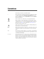
Conventions
The following conventions are used in this manual:
»
The » symbol leads you through nested menu items and dialog box options
to a final action. The sequence File»Page Setup»Options directs you to
pull down the File menu, select the Page Setup item, and select Options
from the last dialog box.
This icon denotes a note, which alerts you to important information.
This icon denotes a caution, which advises you of precautions to take to
avoid injury, data loss, or a system crash. When this symbol is marked on a
product, refer to the Safety section of Appendix A, Specifications, for
information about precautions to take.
When symbol is marked on a product, it denotes a warning advising you to
take precautions to avoid electrical shock.
bold
Bold text denotes items that you must select or click in the software, such
as menu items and dialog box options. Bold text also denotes parameter
names.
italic
Italic text denotes variables, emphasis, a cross-reference, or an introduction
to a key concept. Italic text also denotes text that is a placeholder for a word
or value that you must supply.
monospace
Text in this font denotes text or characters that you should enter from the
keyboard, sections of code, programming examples, and syntax examples.
This font is also used for the proper names of disk drives, paths, directories,
programs, subprograms, subroutines, device names, functions, operations,
variables, filenames, and extensions.
Contents
Chapter 1
General Information
Introduction....................................................................................................................1-1
I/O Ports .........................................................................................................................1-1
Cleaning .........................................................................................................................1-2
Chapter 2
System Setup
Important Safety Information ........................................................................................2-1
Setup ..............................................................................................................................2-2
Touchscreen Calibration..................................................................................2-3
Panel Mounting..............................................................................................................2-4
Chapter 3
Jumpers and Connectors
Jumper and Connector Functions ..................................................................................3-1
Jumper and Connector Locations ..................................................................................3-3
Appendix A
Specifications
Appendix B
Serial Port Settings
Appendix C
Watchdog Timer Programming
Appendix D
Watchdog Timer Programming on WinCE
Appendix E
Accessory Kit Assembly Procedure
© National Instruments Corporation
vii
TPC-2012 User Manual
Contents
Appendix F
Touchscreen Configuration
Appendix G
Fuse Replacement
Appendix H
Technical Support and Professional Services
Index
TPC-2012 User Manual
viii
ni.com
1
General Information
This chapter includes general information about the TPC-2012 Human
Machine Interface (HMI).
Introduction
The TPC-2012 touch panel computer, a state-of-the-art HMI based on an
x86 platform, includes these key features:
•
Fanless—Because the system uses a low-power processor, it does not
need fans, which often are unreliable and cause dust to circulate inside
the equipment.
•
Bright display—The TFT LCD features a 12.1 in. display that meets
industrial demands for clear interfaces.
•
Powerful communication capability—The TPC-2012 is a powerful
I/O interface for easy communication with other devices. The I/O
interface includes serial ports, a parallel port, and Ethernet and
USB 1.1 support. The TPC-2012 also supports the PCI/104 expansion
slot, making it easy to expand with PCI/104 modules.
•
Windows CE support—In addition to Windows XP support, the
TPC-2012 supports the Windows CE and Windows XP embedded
platforms. An optional Windows CE operating system specifically for
the TPC-2012 is available for Windows CE application programmers.
I/O Ports
The TPC-2012 includes the following ports:
•
One parallel port that supports EPP/ ECP modes
•
Four serial ports: RS232 (COM1, COM2, COM3) and RS232/422/485
(COM4)
•
One RJ-45 Ethernet port
•
Two PS/2 ports: 6-pin mini-DIN ports for keyboard and mouse
•
Two USB 2.0 ports compliant with USB 1.0 and 1.1.
•
One PCI/104 slot
© National Instruments Corporation
1-1
TPC-2012 User Manual
Chapter 1
General Information
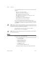
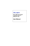
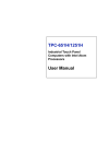
Figure 1-1 shows the I/O port arrangement.
1
2
3
9
1
2
3
PS/2 Mouse
PS/2 Keyboard
USB
5
4
8
4
5
6
7
LAN
Parallel Port
COM1 (RS232)
6
7
8
9
COM2 (RS232)
COM3 (RS232)
COM4 (RS232/422/485)
Figure 1-1. I/O Port Arrangement
For more TPC-2012 specifications, see Appendix A, Specifications.
Cleaning
If you need to clean the unit, use a soft, nonmetallic brush. Make sure that
the unit is completely dry and free from contaminants before returning it to
service.
TPC-2012 User Manual
1-2
ni.com
2
System Setup
This chapter includes setup information for the TPC-2012.
Important Safety Information
Before setting up the TPC-2012, read these safety instructions carefully.
Disconnect this equipment from any AC outlet before cleaning. Use a damp
cloth. Do not use liquid or spray detergents for cleaning.
For plug-in equipment, the power outlet socket must be located near the
equipment and must be easily accessible.
Keep this equipment away from excessive humidity.
Place this equipment on a reliable surface during installation. Dropping it
or letting it fall may cause damage.
The openings on the enclosure are for air convection. Protect the equipment
from overheating. Do not cover the openings.
Make sure the power source voltage is correct before connecting the
equipment to the power outlet.
Position the power cord so that it cannot be stepped on. Do not place
anything over the power cord.
All cautions and warnings on the equipment should be noted.
If the equipment is not used for a long time, disconnect it from the power
source to avoid damage by transient overvoltage.
Never pour any liquid into an opening. This may cause fire or electrical
shock.
Never open the equipment. For safety reasons, only qualified service
personnel should open the equipment.
© National Instruments Corporation
2-1
TPC-2012 User Manual
Chapter 2
System Setup
If one of the following situations arises, have service personnel check the
equipment:
•
The power cord or plug is damaged.
•
Liquid has penetrated into the equipment.
•
The equipment has been exposed to moisture.
•
The equipment does not work well, or you cannot get it to work
according to the user manual.
•
The equipment has been dropped and damaged.
•
The equipment has obvious signs of breakage.
Do not leave this equipment in an environment where the storage
temperature may go below –20 °C (–4 °F) or above 60 °C (140 °F). Doing
so could damage the equipment. The equipment should be in a controlled
environment.
There is a danger of explosion if the battery is incorrectly replaced. Replace the
battery only with the same or equivalent type recommended by the manufacturer. Discard
used batteries according to the manufacturer’s instructions.
Caution
The sound pressure level at the operator’s position according to
IEC 704-1:1982 is no more than 70 dB (A).
The protection this equipment provides may be impaired if it is used in a manner
not described in this manual.
Caution
Setup
Follow these steps to set up the TPC-2012:
1.
Unpack the TPC-2012. Be sure your kit includes the following items:
•
The TPC-2012 HMI
•
Eight panel mounting clamps
•
Eight panel mounting screws
•
One 3-pin power connector
•
One HMI Resource CD
•
One CompactFlash to IDE adapter card
If any items are missing or damaged, contact National Instruments.
TPC-2012 User Manual
2-2
ni.com
Chapter 2
Caution
System Setup
Be sure system power is off before plugging in or pulling out the CompactFlash
card.
2.
Install a CompactFlash card containing Windows CE, embedded
Windows XP, or another operating system.
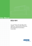
3.
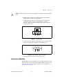
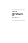
Connect the power connector to 24 VDC power lines. Be sure to
connect the positive, negative, and ground lines as shown in
Figure 2-1. The power lines can be from either a power adapter or
in-house power source.
+ –
GND
Figure 2-1. Power Connector
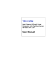
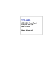
4.
Connect the power connector to the power receptor on the TPC-2012.
The power receptor pin assignment is shown in Figure 2-2.
GND
– +
Figure 2-2. Power Receptor and Pin Assignment
5.
Switch on the power switch to power on the system.
Touchscreen Calibration
The TPC-2012 touchscreen should be correctly calibrated and ready to use
when you power on the system. However, if the calibration is not correct or
you want to choose custom calibration options, refer to Appendix F,
Touchscreen Configuration.
© National Instruments Corporation
2-3
TPC-2012 User Manual
Chapter 2
System Setup
Panel Mounting
Follow these steps to mount the TPC-2012 in a panel:
Note
1.
Be sure the adhesive waterproof gasket on the front bezel is in position.
2.
Install the TPC-2012 in the panel opening. (Refer to Appendix A,
Specifications, for cutout dimensions.)
3.
Hook the clamps included in the accessory pack to the holes around the
four sides of the bezel.
4.
Insert the screws included in the accessory pack into the clamps. To
fasten the TPC-2012 to the panel, tighten the screws so they push
against the mounting panel.
The mounting panel thickness should be less than 6 mm (0.236 in.).
TPC-2012 User Manual
2-4
ni.com
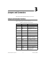
3
Jumpers and Connectors
This chapter describes the TPC-2012 jumpers and connectors.
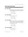
Jumper and Connector Functions
Table 3-1 lists the jumper and connector functions.
Table 3-1. Mainboard Connectors and Jumpers
Label
© National Instruments Corporation
Function
Description
CN2
LCD power
LCD inverter connector
CN3
CF
CompactFlash socket
CN4
IDE
Internal IDE 44-pin (2 mm)
connector
CN5
Ethernet
RJ45 LAN port
CN6
LPT
Printer port
CN7
COM1
Serial port: COM2 RS232
CN8
COM2
Serial port: COM1 RS232
CN9
DC in
DC power in connector
(5.08 mm, 3-pin housing)
CN10
USB2
Two USB type-A female
CN11
USB1
Two USB type-A female
CN12
PS2 mouse
Standard mini-DIN 6-pin
CN13
PS2 keyboard
Standard mini-DIN 6-pin
CN14
PCI104
PCI104 30*4 connector
CN15
COM3
Serial port: COM1 RS232
CN16
COM4
Serial port: COM1
RS232/485/422
3-1
TPC-2012 User Manual
Chapter 3
Jumpers and Connectors
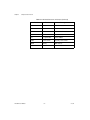
Table 3-1. Mainboard Connectors and Jumpers (Continued)
Label
TPC-2012 User Manual
Function
Description
JP1
Panel
Panel connector
JP2
Touch
Touch connector
JP4
5 V/3 V
PCI104 5 V/3 V select
J1
DDR
DDR connector
J3
1*3 pin header
Clear CMOS
SW1
Power switch
System power switch
BH1
Battery
RTC battery
FS1
Fuse
Fuse holder
3-2
ni.com
Chapter 3
Jumpers and Connectors
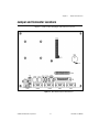
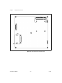
Jumper and Connector Locations
Figures 3-1 and 3-2 show the jumper and connector locations.
Figure 3-1. Main Board Jumpers and Connectors
© National Instruments Corporation
3-3
TPC-2012 User Manual
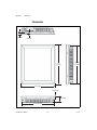
Chapter 3
Jumpers and Connectors
Figure 3-2. Main Board Jumpers and Connectors
TPC-2012 User Manual
3-4
ni.com
A
Specifications
This appendix lists the TPC-2012 system specifications.
Physical
Weight .................................................... 4.1 kg (without HDD)
Cutout dimensions.................................. 302 × 228 mm (suggested)
© National Instruments Corporation
A-1
TPC-2012 User Manual
Appendix A
Specifications
Dimensions
11 [0.433]
7 [0.079]
311
[12.244]
301.49
[11.869]
237 [9.331]
2.5 [0.098]
50 [1.969]
227.49 [8.956]
TPC-2012 User Manual
A-2
ni.com
Appendix A
Specifications
System Kernel
CPU........................................................ GeodeLink Control Processor
LX800 500 MHz
BIOS....................................................... Award 512 KB flash memory
South bridge ........................................... GeodeLink Control Processor
CS5535
VGA ....................................................... GeodeLink Control Processor
LX800 500 MHz
Ethernet .................................................. Realtek RTL8100BL;
IEEE 802.3u protocol compatible
Watchdog timer...................................... W83627 watchdog timer;
1.6 s timeout period
IDE ......................................................... 1 EIDE channel supports one
CompactFlash socket onboard
(Master) and one IDE interface
hard drive (Slave)
Note
COM1 and COM2 support only half-duplex (maximum baud rate: 115.2 Kbps).
LCD
Display type ........................................... TFT color LCD
Size (diagonal) ....................................... 12.1 in.
Maximum resolution .............................. 800 × 600 (SVGA)
Maximum colors .................................... 256,000
Pixel pitch (W × H, mm)........................ 0.3075 × 0.3075
Viewing angle ........................................ 100°
Luminance (cd/m²) ................................. 340
Contrast ratio.......................................... 300
Operating temperature............................ 0 to 50 °C (32 to 122 °F)
(ambient)
© National Instruments Corporation
A-3
TPC-2012 User Manual
Appendix A
Specifications
Backlight.................................................2 CCFL
Backlight lifespan ...................................50,000 h
There may be several bright or dark pixels on the LCD. This phenomenon is normal
in LCD manufacturing.
Note
Touchscreen
Touch type ..............................................Resistive
Base glass construction...........................Tempered Glass
Resolution ...............................................1024 × 1024
Light transmission ..................................75% typical
Controller................................................USB interface
Lifespan ..................................................1 million touches at a single point
Power
Input voltage ...........................................18 to 32 VDC
Typical ....................................................24 VDC, 2.0 A
Fuse
Rating......................................................T3.15 A, 250 V
Size .........................................................5 × 20 mm
Note
When replacing the fuse, use only a fuse of the same type and rating.
Note
For your protection, the fuse is set to break if the input voltage exceeds 33 VDC.
Environment
Operating temperature ............................0 to 50 °C (32 to 122 °F)
Storage temperature ................................–20 to 60 °C (–4 to 140 °F)
Humidity .................................................40 °C @ 10 to 95% relative
humidity (noncondensing)
TPC-2012 User Manual
A-4
ni.com
Appendix A
Specifications
Vibration ................................................ 1 grms (5 to 500 Hz)
Maximum altitude .................................. 2,000 m
Pollution Degree .................................... 2
Indoor use only
Safety
This product is designed to meet the requirements of the following
standards of safety for information technology equipment:
•
IEC 60950-1, EN 60950-1
•
UL 60950-1, CSA 60950-1
Note For UL and other safety certifications, refer to the product label or visit
ni.com/certification, search by model number or product line, and click the
appropriate link in the Certification column.
Electromagnetic Compatibility
This product is designed to meet the requirements of the following
standards of EMC for electrical equipment for measurement, control,
and laboratory use:
Note
•
EN 55024, CISPR 24 EMC requirements
•
EN 55022, CISPR 22 Emissions; Class A
•
EN 55011, CISPR 11 Emissions; Class A
•
CE, C-Tick, ICES, and FCC Part 15 Emissions; Class A
For EMC compliance, operate this device according to product documentation.
CE Compliance
This product meets the essential requirements of applicable European
Directives, as amended for CE marking, as follows:
•
2006/95/EC; Low-Voltage Directive (safety)
•
2004/108/EEC; Electromagnetic Compatibility Directive (EMC)
Refer to the Declaration of Conformity (DoC) for this product for any additional
regulatory compliance information. To obtain the DoC for this product, visit ni.com/
certification, search by model number or product line, and click the appropriate link
in the Certification column.
Note
© National Instruments Corporation
A-5
TPC-2012 User Manual
Appendix A
Specifications
Environmental Management
National Instruments is committed to designing and manufacturing
products in an environmentally responsible manner. NI recognizes that
eliminating certain hazardous substances from our products is beneficial
not only to the environment but also to NI customers.
For additional environmental information, refer to the NI and the
Environment Web page at ni.com/environment. This page contains the
environmental regulations and directives with which NI complies, as well
as any other environmental information not included in this document.
Waste Electrical and Electronic Equipment (WEEE)
At the end of their life cycle, all products must be sent to a WEEE recycling
center. For more information about WEEE recycling centers and National Instruments
WEEE initiatives, visit ni.com/environment/weee.htm.
EU Customers
⬉ᄤֵᙃѻક∵ᶧࠊㅵ⧚ࡲ⊩ ˄Ё RoHS˅
Ёᅶ᠋ National Instruments ヺড়Ё⬉ᄤֵᙃѻકЁ䰤ࠊՓ⫼ᶤѯ᳝ᆇ⠽䋼ᣛҸ (RoHS)DŽ
݇Ѣ National Instruments Ё RoHS ড়㾘ᗻֵᙃˈ䇋ⱏᔩ ni.com/environment/rohs_chinaDŽ
(For information about China RoHS compliance, go to ni.com/environment/rohs_china.)
Mercury Disposal and Recycling
LCD lamp(s) in this monitor contain mercury. Dispose or recycle according
to local, state or federal laws. Consult the Electronic Industries Alliance at
www.eiae.org for more information. For specific information on lamp
disposal, consult www.lamprecycle.org.
Cleaning
If you need to clean the unit, use a soft, nonmetallic brush. Make sure that
the unit is completely dry and free from contaminants before returning it to
service.
TPC-2012 User Manual
A-6
ni.com
B
Serial Port Settings
This appendix describes the TPC-2012 serial port settings.
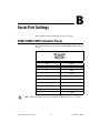
COM1/COM2/COM3 Connector Pinout
The following figure and table show the COM1/COM2/COM3 connector
pinout.
Note
1
5
6
9
Pin
Signal
1
NDCD
2
NRX
3
NTX
4
NDTR
5
GND
6
NDSR
7
NRTS
8
NCTS
9
NRI
COM1 and COM2 support only half-duplex (maximum baud rate: 115.2 Kbps).
© National Instruments Corporation
B-1
TPC-2012 User Manual
Appendix B
Serial Port Settings
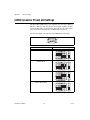
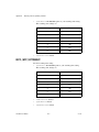
COM4 Connector Pinout and Settings
The TPC-2012 COM4 serial port is adjustable. You can set it to RS-232,
RS-422, or RS-485, and it has auto data flow control capability. In other
words, the TPC-2012 can automatically detect the data flow direction at
this port when two-wired RS-485 communication is activated.
The following figure and table show the COM4 pinout and settings.
1
5
6
9
COM4 Mode
S1 and S2 Setting
RS232 Mode
RS485 Mode
RS422 Master Mode
RS422 Slave Mode
TPC-2012 User Manual
B-2
ni.com
Appendix B
© National Instruments Corporation
Serial Port Settings
PIN
RS-232
RS-422
RS-485
1
NDCD
TX–
D–
2
NRX
TX+
D+
3
NTX
RX+
4
NDTR
RX–
5
GND
GND
6
NDSR
7
NRTS
8
NCTS
9
NRI
B-3
GND
TPC-2012 User Manual
C
Watchdog Timer Programming
This appendix explains the TPC-2012 watchdog timer programming.
Overview
You can use the TPC-2012 watchdog timer to monitor system software
operation and take corrective action if the software fails to function after the
programmed period. This appendix describes how to program the
watchdog timer operation.
The watchdog timer is built into the W83627HF I/O controller. It includes
the following programmable functions:
•
You can enable and disable the timer via programming.
•
You can set the timer interval from 1 to 255 seconds or 1 to
255 minutes.
•
The timer generates an interrupt or resets the signal if the software fails
to reset the timer after a timeout.
Watchdog Timer Programming
The watchdog timer I/O port address is 2E (hex) (the address port) and
2F (hex) (the data port). You must first assign the register address by
writing the address value to address port 2E (hex), then write/read data
to/from the assigned register through data port 2F (hex).
© National Instruments Corporation
C-1
TPC-2012 User Manual
Appendix C
Watchdog Timer Programming
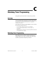
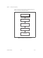
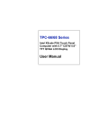
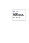
Figure C-1 describes the watchdog timer programming procedure, and
Table C-1 describes the watchdog timer registers.
Unlock W83627
Select Watchdog Timer Register
Enable Watchdog Timer Function
Use Watchdog Timer Function
Lock W83627HF
Figure C-1. Watchdog Timer Programming Procedure
TPC-2012 User Manual
C-2
ni.com
Appendix C
Watchdog Timer Programming
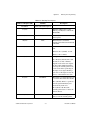
Table C-1. Watchdog Timer Registers
Address of Register (2E)
Attribute
Description
Read/Write
Value (2F) and description
—
87 (hex)
—
Write this address twice to I/O
address port 2E (hex) to unlock the
W83627HF.
07 (hex)
Write
Write 08 (hex) to select the watchdog
timer register.
30 (hex)
Write
Write 01 (hex) to enable the
watchdog timer function. The default
is disabled.
F5 (hex)
Write
Set seconds or minutes as the timer
unit.
Write 0 to bit 3 (default): second.
Write 1 to bit 3: minute.
F6 (hex)
Write
0: Stop timer
01 to FF (hex) (default): The count
amount, in seconds or minutes,
depends on the value set in register
F5 (hex). This number determines
how long the watchdog timer waits
for the strobe before generating an
interrupt or reset signal. Writing a
new value to this register resets the
timer to count with the new value.
F7 (hex)
Read/Write
Bit 6: Write 1 to enable the keyboard
to reset the timer. Write 0 to disable.
Bit 5 (default): Write 1 to generate a
timeout signal immediately and
automatically return to 0.
Bit 4 (default = 0): Read the
watchdog timer status. 1 means the
timer is timeout.
AA (hex)
© National Instruments Corporation
—
Write this address to I/O port 2E
(hex) to lock the watchdog timer.
C-3
TPC-2012 User Manual
Appendix C
Watchdog Timer Programming
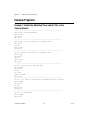
Example Programs
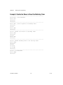
Example 1: Enable the Watchdog Timer and Set 10 s as the
Timeout Interval
;----------------------------------------------------------Mov dx,2eh ; Unlock W83627HF
Mov al,87h
Out dx,al
Out dx,al
;----------------------------------------------------------Mov al,07h ; Select registers of watchdog timer
Out dx,al
Inc dx
Mov al,08h
Out dx,al
;----------------------------------------------------------Dec dx ; Enable the function of watchdog timer
Mov al,30h
Out dx,al
Inc dx
Mov al,01h
Out dx,al
;----------------------------------------------------------Dec dx ; Set second as counting unit
Mov al,0f5h
Out dx,al
Inc dx
In al,dx
And al,not 08h
Out dx,al
;----------------------------------------------------------Dec dx ; Set timeout interval as 10 seconds and start counting
Mov al,0f6h
Out dx,al
Inc dx
Mov al,10
Out dx,al
;----------------------------------------------------------Dec dx ; lock W83627HF
Mov al,0aah
Out dx,al
TPC-2012 User Manual
C-4
ni.com
Appendix C
Watchdog Timer Programming
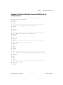
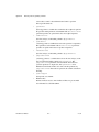
Example 2: Enable the Watchdog Timer and Set 5 Min as the
Timeout Interval
;----------------------------------------------------------Mov dx,2eh ; unlock W83627H
Mov al,87h
Out dx,al
Out dx,al
;----------------------------------------------------------Mov al,07h ; Select registers of watchdog timer
Out dx,al
Inc dx
Mov al,08h
Out dx,al
;----------------------------------------------------------Dec dx ; Enable the function of watchdog timer
Mov al,30h
Out dx,al
Inc dx
Mov al,01h
Out dx,al
;----------------------------------------------------------Dec dx ; Set minute as counting unit
Mov al,0f5h
Out dx,al
Inc dx
In al,dx
Or al,08h
Out dx,al
;----------------------------------------------------------Dec dx ; Set timeout interval as 5 minutes and start counting
Mov al,0f6h
Out dx,al
Inc dx
Mov al,5
Out dx,al
;----------------------------------------------------------Dec dx ; lock W83627HF
Mov al,0aah
Out dx,al
© National Instruments Corporation
C-5
TPC-2012 User Manual
Appendix C
Watchdog Timer Programming
Example 3: Enable the Mouse to Reset the Watchdog Timer
;----------------------------------------------------------Mov dx,2eh ; unlock W83627H
Mov al,87h
Out dx,al
Out dx,al
;----------------------------------------------------------Mov al,07h ; Select registers of watchdog timer
Out dx,al
Inc dx
Mov al,08h
Out dx,al
;----------------------------------------------------------Dec dx ; Enable the function of watchdog timer
Mov al,30h
Out dx,al
Inc dx
Mov al,01h
Out dx,al
;----------------------------------------------------------Dec dx ; Enable watchdog timer to be reset by mouse
Mov al,0f7h
Out dx,al
Inc dx
In al,dx
Or al,80h
Out dx,al
;----------------------------------------------------------Dec dx ; lock W83627HF
Mov al,0aah
Out dx,al
TPC-2012 User Manual
C-6
ni.com
Appendix C
Watchdog Timer Programming
Example 4: Enable the Keyboard to Reset the Watchdog Timer
;----------------------------------------------------------Mov dx,2eh ; unlock W83627H
Mov al,87h
Out dx,al
Out dx,al
;----------------------------------------------------------Mov al,07h ; Select registers of watchdog timer
Out dx,al
Inc dx
Mov al,08h
Out dx,al
;----------------------------------------------------------Dec dx ; Enable the function of watchdog timer
Mov al,30h
Out dx,al
Inc dx
Mov al,01h
Out dx,al
;----------------------------------------------------------Dec dx ; Enable watchdog timer to be strobed reset by keyboard
Mov al,0f7h
Out dx,al
Inc dx
In al,dx
Or al,40h
Out dx,al
;----------------------------------------------------------Dec dx ; lock W83627HF
Mov al,0aah
Out dx,al
© National Instruments Corporation
C-7
TPC-2012 User Manual
Appendix C
Watchdog Timer Programming
Example 5: Generate a Timeout Signal without Timer Counting
;----------------------------------------------------------Mov dx,2eh ; unlock W83627H
Mov al,87h
Out dx,al
Out dx,al
;----------------------------------------------------------Mov al,07h ; Select registers of watchdog timer
Out dx,al
Inc dx
Mov al,08h
Out dx,al
;----------------------------------------------------------Dec dx ; Enable the function of watchdog timer
Mov al,30h
Out dx,al
Inc dx
Mov al,01h
Out dx,al
;----------------------------------------------------------Dec dx ; Generate a time-out signal
Mov al,0f7h
Out dx,al ;Write 1 to bit 5 of F7 register
Inc dx
In al,dx
Or al,20h
Out dx,al
;----------------------------------------------------------Dec dx ; lock W83627HF
Mov al,0aah
Out dx,al
TPC-2012 User Manual
C-8
ni.com
Watchdog Timer Programming
on WinCE
D
Windows CE includes a watchdog timer for the TPC-2012. You can access
the timer through the WIN32 API. The TPC-2012 includes a WDT driver,
WDT1:, for enabling/disabling the watchdog timer. You must open this
driver before using the resources, and then use the DeviceIOControl
function to enable/disable the watchdog timer.
This appendix describes DeviceIOControl and it parameters. It also
includes a programming example.
DeviceIOControl
DeviceIOControl sends a control code directly to a specified device driver,
causing the corresponding device to perform the specified operation. The
function and its parameters are:
BOOL DeviceIoControl( HANDLE hDevice, DWORD
dwIoControlCode, LPVOID lpInBuffer, DWORD nInBufferSize,
LPVOID lpOutBuffer, DWORD nOutBufferSize, LPDWORD
lpBytesReturned, LPOVERLAPPED lpOverlapped );
Parameters
DeviceIOControl includes the following parameters:
•
hDevice
(in) Handle to the device that performs the operation. Call the
CreateFile function to obtain a device handle.
•
dwIoControlCode
(in) Specifies the operation control code. This value identifies the
specific operation to be performed and the type of device on which the
operation is to be performed. No specific values are defined for the
dwIoControlCode parameter. However, if you write a custom device
driver, you can define IOCTL_XXXX control codes, per the CTL_CODE
macro. You then can advertise these control codes, and an application
© National Instruments Corporation
D-1
TPC-2012 User Manual
Appendix D
Watchdog Timer Programming on WinCE
can use these control codes with DeviceIoControl to perform
driver-specific functions.
•
lpInBuffer
(in) Long pointer to a buffer that contains the data required to perform
the operation. This parameter can be NULL if the dwIoControlCode
parameter specifies an operation that does not require input data.
•
nInBufferSize
(in) Size, in bytes, of the buffer pointed to by lpInBuffer.
•
lpOutBuffer
(out) Long pointer to a buffer that receives the operation’s output data.
This parameter can be NULL if the dwIoControlCode parameter
specifies an operation that does not produce output data.
•
nOutBufferSize
(in) Size, in bytes, of the buffer pointed to by lpOutBuffer.
•
lpBytesReturned
(out) Long pointer to a variable that receives the size, in bytes, of the
data stored into the buffer pointed to by lpOutBuffer. The
lpBytesReturned parameter cannot be NULL. Even when an
operation produces no output data, and lpOutBuffer can be
NULL, DeviceIoControl makes use of the variable pointed to by
lpBytesReturned. After such an operation, the variable value has no
meaning.
•
lpOverlapped
(in) Ignored; set to NULL.
•
Return Values
Nonzero indicates success. Zero indicates failure. To get extended
error information, call GetLastError.
TPC-2012 User Manual
D-2
ni.com
Appendix D
Watchdog Timer Programming on WinCE
How to Use the Control Codes
There are six control codes for the WDT driver operation codes.
IOCTL _WDT_ENABLE
Enables the application watchdog timer. By default, if the watchdog timer
is enabled, the WDT driver automatically triggers itself after the specified
period, and your application does not need to trigger the watchdog timer.
•
lpInBuffer: unused
•
nInBufferSize: unused
•
lpOutBuffer: unused
•
nOutBufferSize: unused
IOCTL _WDT_DISABLE
Disables the application watchdog timer.
•
lpInBuffer: unused
•
nInBufferSize: unused
•
lpOutBuffer: unused
•
nOutBufferSize: unused
IOCTL_WDT_STROBE
Triggers the watchdog. If your application uses IOCTL_WDT_ENABLE
to enable the watchdog first and then sends IOCTL_WDT_REBOOT to the
WDT driver, your application must trigger the watchdog once during the
watchdog timer period. If your application has not triggered at the specified
period, the device reboots automatically.
•
lpInBuffer: unused
•
nInBufferSize: unused
•
lpOutBuffer: unused
•
nOutBufferSize: unused
IOCTL_WDT_GETTIMEOUT
Gets the watchdog time setting.
•
lpInBuffer: unused
•
nInBufferSize: unused
© National Instruments Corporation
D-3
TPC-2012 User Manual
Appendix D
Watchdog Timer Programming on WinCE
•
lpOutBuffer: The DWORD points to your watchdog time setting.
The watchdog time settings are:
•
Setting
Time
0
2s
1 (default)
5 s (default)
2
10 s
3
15 s
4
30 s
5
45 s
6
60 s
nOutBufferSize: unused
IOCTL_WDT_SETTIMEOUT
Sets the watchdog time setting.
•
TPC-2012 User Manual
lpInBuffer: The DWORD points to your watchdog time setting.
The watchdog time settings are:
Setting
Time
0
2s
1 (default)
5 s (default)
2
10 s
3
15 s
4
30 s
5
45 s
6
60 s
•
nInBufferSize: unused
•
lpOutBuffer: unused
•
nOutBufferSize: unused
D-4
ni.com
Appendix D
Watchdog Timer Programming on WinCE
IOCTL_WDT_REBOOT
If you want your application to trigger the watchdog, use
IOCTL_WDT_REBOOT to notify the watchdog driver timer (WDT).
Otherwise, the WDT triggers itself automatically.
•
lpInBuffer: unused
•
nInBufferSize: unused
•
lpOutBuffer: unused
•
nOutBufferSize: unused
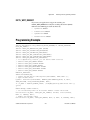
Programming Example
#define WDT_CODE(ID) CTL_CODE(FILE_DEVICE_UNKNOWN,ID, METHOD_BUFFERED,
FILE_ANY_ACCESS)
#define IOCTL_WDT_ENABLE WDT_CODE (0x900)
#define IOCTL_WDT_DISABLE WDT_CODE(0x901)
#define IOCTL_WDT_STROBE WDT_CODE(0x902)
#define IOCTL_WDT_GET_TIMEOUT WDT_CODE(0x903)
#define IOCTL_WDT_SET_TIMEOUT WDT_CODE(0x904)
#define IOCTL_WDT_REBOOT WDT_CODE(0x905)
// for compatibility reasons, you can define IOCTL as below:
// #define IOCTL_WDT_ENABLE 0x1001
// #define IOCTL_WDT_DISABLE 0x1002
// #define IOCTL_WDT_STROBE 0x1003
// #define IOCTL_WDT_GETTIMEOUT 0x1004
// #define IOCTL_WDT_SETTIMEOUT 0x1005
// #define IOCTL_WDT_REBOOT 0x1006
HANDLE m_hWDT=NULL;
TCHAR szClassName[60];
// assign the WDT driver name wsprintf(szClassName, TEXT("WDT1:"));
// Open the WDT driver
m_hWDT = CreateFile(szClassName, GENERIC_READ GENERIC_WRITE, 0, NULL,
OPEN_EXISTING, FILE_ATTRIBUTE_NORMAL, NULL);
if ( m_hWDT == INVALID_HANDLE_VALUE ) { DebugMsg(CString("WDT driver fail"));
return;
}
DWORD dwTemp; DWORD nIndex=2;
// Set the Watchdog Timer as 10 seconds. Number 2 means 10 seconds.
DeviceIoControl(m_hWDT, IOCTL_WDT_SET_TIMEOUT, &nIndex, sizeof(nIndex),
NULL, 0, &dwTemp, NULL);
// Enable the Watchdog timer
DeviceIoControl(m_hWDT, IOCTL_WDT_ENABLE, NULL, 0, NULL, 0, &dwTemp, NULL);
© National Instruments Corporation
D-5
TPC-2012 User Manual
Appendix D
Watchdog Timer Programming on WinCE
While (1) {
// do your job here.
Sleep(8000);
DeviceIoControl(m_hWDT, IOCTL_WDT_STROBE, NULL,0, NULL, 0, &dwTemp, NULL);
}
DeviceIoControl(m_hWDT, IOCTL_WDT_DISABLE, NULL, , NULL, 0, &dwTemp, NULL);
CloseHandle(m_hWDT);
TPC-2012 User Manual
D-6
ni.com
E
Accessory Kit Assembly
Procedure
This appendix explains how to connect to a CD-ROM via the
CompactFlash slot.
CompactFlash to IDE Transfer Kit Assembly
Follow these steps to connect to a CD-ROM via the CompactFlash slot:
1.
Connect the IDE cable to the adapter board.
2.
Insert the adapter board into the CompactFlash slot.
3.
Connect the CD-ROM to the IDE cable.
4.
Connect the external power line to the CD-ROM.
© National Instruments Corporation
E-1
TPC-2012 User Manual
Touchscreen Configuration
F
This appendix explains how to configure the TPC-2012 touchscreen using
the PenMount Control Panel.
Touchscreen Calibration
To calibrate the TPC-2012, go to Start»Control Panel»Stylus, which
displays the Stylus Properties screen. You can set the double-tap sensitivity
in the Double-Tap tab. To recalibrate the stylus, use the Calibration tab.
Press the Recalibrate button, then press and briefly hold the stylus on the
center of each target as it appears on the screen. When finished, tap on the
screen with the stylus to save the settings.
© National Instruments Corporation
F-1
TPC-2012 User Manual
G
Fuse Replacement
Caution Do not replace the fuse unless it is damaged. Do not replace the fuse with a
differently rated fuse. For more information, see the fuse specifications in Appendix A,
Specifications.
Follow these steps to replace the fuse:
1.
Remove the fuse cover.
2.
Replace the damaged fuse with a new one.
3.
Place the fuse cover back into position.
© National Instruments Corporation
G-1
TPC-2012 User Manual
Technical Support and
Professional Services
H
Visit the following sections of the National Instruments Web site at
ni.com for technical support and professional services:
•
Support—Online technical support resources at ni.com/support
include the following:
–
Self-Help Resources—For answers and solutions, visit the
award-winning National Instruments Web site for software drivers
and updates, a searchable KnowledgeBase, product manuals,
step-by-step troubleshooting wizards, thousands of example
programs, tutorials, application notes, instrument drivers, and
so on.
–
Free Technical Support—All registered users receive free Basic
Service, which includes access to hundreds of Application
Engineers worldwide in the NI Discussion Forums at
ni.com/forums. National Instruments Application Engineers
make sure every question receives an answer.
For information about other technical support options in your
area, visit ni.com/services or contact your local office at
ni.com/contact.
•
Training and Certification—Visit ni.com/training for
self-paced training, eLearning virtual classrooms, interactive CDs,
and Certification program information. You also can register for
instructor-led, hands-on courses at locations around the world.
•
System Integration—If you have time constraints, limited in-house
technical resources, or other project challenges, National Instruments
Alliance Partner members can help. To learn more, call your local
NI office or visit ni.com/alliance.
If you searched ni.com and could not find the answers you need, contact
your local office or NI corporate headquarters. Phone numbers for our
worldwide offices are listed at the front of this manual. You also can visit
the Worldwide Offices section of ni.com/niglobal to access the branch
office Web sites, which provide up-to-date contact information, support
phone numbers, email addresses, and current events.
© National Instruments Corporation
H-1
TPC-2012 User Manual
Index
A
E
accessory kit assembly, E-1
electromagnetic compatibility
specifications, A-5
environmental management, A-6
environmental specifications, A-4
example programs
watchdog timer, C-4
examples (NI resources), H-1
C
CE compliance specifications, A-5
cleaning, 1-2, A-6
COM1/COM2/COM3 connector pinout, B-1
COM4 connector pinout and settings, B-2
CompactFlash to IDE transfer kit
assembly, E-1
connectors, 3-1
function descriptions (table), 3-1
locations (table), 3-3, 3-4
control codes, using, D-3
conventions used in the manual, v
F
fuse
replacement, G-1
specifications, A-4
H
help, technical support, H-1
D
DeviceIOControl, D-1
control codes
IOCTL _WDT_DISABLE, D-3
IOCTL _WDT_ENABLE, D-3
IOCTL_WDT_GETTIMEOUT, D-3
IOCTL_WDT_REBOOT, D-5
IOCTL_WDT_SETTIMEOUT, D-4
IOCTL_WDT_STROBE, D-3
using, D-3
parameters, D-1
diagnostic tools (NI resources), H-1
dimensions, A-2
documentation
conventions used in the manual, v
NI resources, H-1
drivers (NI resources), H-1
© National Instruments Corporation
I
I/O ports, 1-1
arrangement (figure), 1-2
instrument drivers (NI resources), H-1
introduction, 1-1
IOCTL _WDT_DISABLE, D-3
IOCTL _WDT_ENABLE, D-3
IOCTL_WDT_GETTIMEOUT, D-3
IOCTL_WDT_REBOOT, D-5
IOCTL_WDT_SETTIMEOUT, D-4
IOCTL_WDT_STROBE, D-3
J
jumpers, 3-1
function descriptions (table), 3-1
locations (table), 3-3, 3-4
I-1
TPC-2012 User Manual
Index
K
National Instruments support and
services, H-1
electromagnetic compatibility, A-5
environmental, A-4
environmental management, A-6
fuse, A-4
LCD, A-3
mercury disposal and recycling, A-6
physical, A-1
power, A-4
safety, A-5
system kernel, A-3
touchscreen, A-4
Waste Electrical and Electronic
Equipment compliance, A-6
support, technical, H-1
system kernel specifications, A-3
system setup, 2-2
P
T
panel mounting, 2-4
physical specifications, A-1
pinouts
COM1/COM2/COM3 connector, B-1
COM4 connector, B-2
power connector (figure), 2-3
power receptor (figure), 2-3
power specifications, A-4
programming examples (NI resources), H-1
technical support, H-1
touchscreen
calibration, 2-3, F-1
specifications, A-4
TPC-2012
CE compliance specifications, A-5
cleaning specifications, 1-2, A-6
COM1/COM2/COM3 connector pinout,
B-1
COM4 connector pinout and settings, B-2
CompactFlash to IDE transfer kit
assembly, E-1
connectors, 3-1
dimensions, A-2
electromagnetic compatibility
specifications, A-5
environmental management
specifications, A-6
environmental specifications, A-4
fuse
replacement, G-1
specifications, A-4
KnowledgeBase, H-1
L
LCD specifications, A-3
M
mercury disposal and recycling
specifications, A-6
N
S
safety
information, 2-1
specifications, A-5
serial port settings, B-1
setup, 2-2
software (NI resources), H-1
specifications, A-1
CE compliance, A-5
cleaning, 1-2, A-6
dimensions, A-2
TPC-2012 User Manual
I-2
ni.com
Index
W
I/O ports, 1-1
introduction, 1-1
jumpers, 3-1
LCD specifications, A-3
mercury disposal and recycling
specifications, A-6
panel mounting, 2-4
physical specifications, A-1
power connector (figure), 2-3
power receptor (figure), 2-3
power specifications, A-4
safety
information, 2-1
specifications, A-5
serial port settings, B-1
specifications, A-1
system kernel specifications, A-3
system setup, 2-2
touchscreen
calibration, 2-3
specifications, A-4
Waste Electrical and Electronic
Equipment specifications, A-6
watchdog timer programming, C-1
example programs, C-4
on Win CE, D-1
DeviceIOControl, D-1
overview, C-1
procedure (figure), C-2
registers (table), C-3
training and certification (NI resources), H-1
troubleshooting (NI resources), H-1
© National Instruments Corporation
Waste Electrical and Electronic Equipment
compliance specifications, A-6
watchdog timer programming, C-1
example programs, C-4
enabling the keyboard to reset the
watchdog timer, C-7
enabling the mouse to reset the
watchdog timer, C-6
enabling the watchdog timer and
setting 10 seconds as the timeout
interval, C-4
enabling the watchdog timer and
setting 5 minutes as the timeout
interval, C-5
generating a timeout signal without
timer counting, C-8
on WinCE, D-1
DeviceIOControl, D-1
programming example, D-5
overview, C-1
procedure (figure), C-2
registers (table), C-3
Web resources, H-1
I-3
TPC-2012 User Manual