1
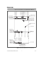
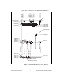
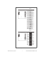
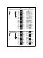
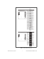
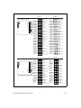
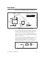
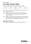
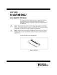
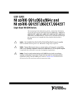
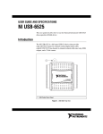
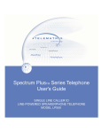
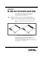
USER GUIDE
NI USB-6221/6229/6251/6259 OEM
This document provides dimensions, pinouts, and information
about the connectors, switch, LEDs, and chassis ground of the
NI USB-6221/6229/6251/6259 OEM devices.
There are no product safety, electromagnetic compatibility (EMC), or
CE marking compliance claims made for the USB-6221/6229/6251/6259 OEM devices.
Conformity to any and all compliance requirements rests with the end product supplier.
Caution
Figure 1 shows the USB-6221/6251 OEM and USB-6229/6259 OEM
devices.
USB-6221/6251
USB-6229/6259
Figure 1. USB-6221/6251 and USB-6229/6259 OEM Devices
Refer to the NI 622x Specifications document for USB-6221/6229
specifications and the NI 625x Specifications document for
USB-6251/6259 specifications. Refer to the M Series User Manual for
more information about USB-6221/6229/6251/6259 devices. You can find
all documentation at ni.com/manuals.
Dimensions
5.900 (149.86)
6.013 (152.74)
5.210 (132.33)
3.198 (81.22)
3.220 (81.79)
3.730 (94.74)
3.734 (94.84)
4.110 (104.39)
3.180 (80.77)
0.200 (5.08)
0.390 (9.91)
0.918 (23.32)
Figure 2 shows the dimensions of the USB-6221/6251 OEM device.
6.950 (176.53)
4x 6.718 (170.63)
6.270 (159.26)
6.140 (155.96)
5.930 (150.62)
4X Ø 0.110 (2.79)
7X Ø 0.125 (3.18)
6.140 (155.96)
5.760 (146.30)
5.290 (134.37)
5.080 (129.03)
2X Ø 0.156 (3.96)
2.535 (64.39)
0.396 (10.06)
0.304 (7.72)
0.256 (6.50)
0.116 (2.95)
0.000 (0.00)
6.200 (157.48)
6.400 (162.56)
4.780 (121.41)
3.296 (83.72)
3.080 (78.23)
2.072 (52.63)
2.300 (58.42)
2.606 (66.19)
1.750 (44.45)
0.200 (5.08)
1.057 (26.85)
0.436 (11.07)
0.392 (9.96)
0.362 (9.19)
0.162 (4.11)
0.062 (1.57)
0.000 (0.00)
0.393 (9.98)
0.000 (0.00)
0.304 (7.72)
0.200 (5.08)
0.515 (13.08)
2X Ø 0.140 Cutout
in Panel for LEDs
Ø 0.330 Cutout in Panel
for Power Connector
Figure 2. USB-6221/6251 OEM Dimensions in Inches (Millimeters)
NI USB-6221/6229/6251/6259 OEM User Guide
2
ni.com
5.900 (149.86)
6.013 (152.74)
5.210 (132.33)
3.198 (81.22)
3.220 (81.79)
3.730 (94.74)
3.734 (94.84)
4.110 (104.39)
3.180 (80.77)
0.200 (5.08)
0.390 (9.91)
0.918 (23.32)
Figure 3 shows the dimensions of the USB-6229/6259 OEM device.
6.950 (176.53)
4x 6.718 (170.63)
6.270 (159.26)
6.140 (155.96)
5.930 (150.62)
5.839 (148.31)
5.499 (139.67)
4X Ø 0.110 (2.79)
7X Ø 0.125 (3.18)
6.140 (155.96)
5.760 (146.30)
5.290 (134.37)
5.080 (129.03)
2X Ø 0.156 (3.96)
2.535 (64.39)
0.396 (10.06)
0.304 (7.72)
0.256 (6.50)
0.116 (2.95)
0.000 (0.00)
6.200 (157.48)
6.400 (162.56)
4.780 (121.41)
3.296 (83.72)
3.080 (78.23)
2.072 (52.63)
2.300 (58.42)
2.606 (66.19)
1.750 (44.45)
0.200 (5.08)
1.057 (26.85)
0.436 (11.07)
0.392 (9.96)
0.362 (9.19)
0.162 (4.11)
0.062 (1.57)
0.000 (0.00)
0.393 (9.98)
0.000 (0.00)
0.304 (7.72)
0.200 (5.08)
0.515 (13.08)
2X Ø 0.140 Cutout
in Panel for LEDs
Ø 0.330 Cutout in Panel
for Power Connector
Figure 3. USB-6229/6259 OEM Dimensions in Inches (Millimeters)
© National Instruments Corporation
3
NI USB-6221/6229/6251/6259 OEM User Guide
I/O Connector Pinouts
Figures 4 through 7 show the connector pinouts for the USB-6221 OEM,
USB-6229 OEM, USB-6251 OEM, and USB-6259 OEM devices.
Refer to the M Series User Manual at ni.com/manuals for more
information about USB-6221/6229/6251/6259 signals and how to
connect them.
NI USB-6221/6229/6251/6259 OEM User Guide
4
ni.com
Bank 0
50-Pin Digital Connector
+5 V
D GND
D GND
D GND
D GND
D GND
D GND
D GND
D GND
D GND
D GND
D GND
D GND
D GND
D GND
D GND
D GND
D GND
D GND
D GND
D GND
D GND
D GND
D GND
D GND
50
48
46
44
42
40
38
36
34
32
30
28
26
24
22
20
18
16
14
12
10
8
6
4
2
49
47
45
43
41
39
37
35
33
31
29
27
25
23
21
19
17
15
13
11
9
7
5
3
1
+5 V
PFI 15
PFI 14
PFI 13
PFI 12
PFI 11
PFI 10
PFI 9
PFI 8
PFI 7
PFI 6
PFI 5
PFI 4
PFI 3
PFI 2
PFI 1
PFI 0
P0.7
P0.6
P0.5
P0.4
P0.3
P0.2
P0.1
P0.0
Bank 0
34-Pin Analog Connector
AI GND
AI 7
AI 14
AI GND
AI 5
AI 12
AI GND
AI 3
AI 10
AI GND
AI 1
AI 8
AI GND
AI GND
AI GND
AO 1
AO 0
34
32
30
28
26
24
22
20
18
16
14
12
10
8
6
4
2
33
31
29
27
25
23
21
19
17
15
13
11
9
7
5
3
1
AI 15
AI GND
AI 6
AI 13
AI GND
AI 4
AI 11
AI GND
AI 2
AI 9
AI GND
AI 0
AI SENSE
NC
AO GND
AO GND
AO GND
NC = No Connect
Figure 4. USB-6221 OEM Connector Pinout
© National Instruments Corporation
5
NI USB-6221/6229/6251/6259 OEM User Guide
Bank 1
50-Pin Digital Connectors
50
48
46
44
42
40
38
36
34
32
30
28
26
24
22
20
18
16
14
12
10
8
6
4
2
+5 V
D GND
D GND
D GND
D GND
D GND
D GND
D GND
D GND
D GND
D GND
D GND
D GND
D GND
D GND
D GND
D GND
D GND
D GND
D GND
D GND
D GND
D GND
D GND
D GND
49
47
45
43
41
39
37
35
33
31
29
27
25
23
21
19
17
15
13
11
9
7
5
3
1
Bank 0
+5 V
P0.31
P0.30
P0.29
P0.28
P0.27
P0.26
P0.25
P0.24
P0.23
P0.22
P0.21
P0.20
P0.19
P0.18
P0.17
P0.16
P0.15
P0.14
P0.13
P0.12
P0.11
P0.10
P0.9
P0.8
+5 V
D GND
D GND
D GND
D GND
D GND
D GND
D GND
D GND
D GND
D GND
D GND
D GND
D GND
D GND
D GND
D GND
D GND
D GND
D GND
D GND
D GND
D GND
D GND
D GND
Bank 1
34-Pin Analog Connectors
AI GND
AI 23
AI 30
AI GND
AI 21
AI 28
AI GND
AI 19
AI 26
AI GND
AI 17
AI 24
AI GND
AI GND
AI GND
AO 3
AO 2
34
32
30
28
26
24
22
20
18
16
14
12
10
8
6
4
2
33
31
29
27
25
23
21
19
17
15
13
11
9
7
5
3
1
50
48
46
44
42
40
38
36
34
32
30
28
26
24
22
20
18
16
14
12
10
8
6
4
2
49
47
45
43
41
39
37
35
33
31
29
27
25
23
21
19
17
15
13
11
9
7
5
3
1
+5 V
PFI 15
PFI 14
PFI 13
PFI 12
PFI 11
PFI 10
PFI 9
PFI 8
PFI 7
PFI 6
PFI 5
PFI 4
PFI 3
PFI 2
PFI 1
PFI 0
P0.7
P0.6
P0.5
P0.4
P0.3
P0.2
P0.1
P0.0
Bank 0
AI 31
AI GND
AI 22
AI 29
AI GND
AI 20
AI 27
AI GND
AI 18
AI 25
AI GND
AI 16
AI SENSE 2
NC
AO GND
AO GND
AO GND
NC = No Connect
AI GND
AI 7
AI 14
AI GND
AI 5
AI 12
AI GND
AI 3
AI 10
AI GND
AI 1
AI 8
AI GND
AI GND
AI GND
AO 1
AO 0
34
32
30
28
26
24
22
20
18
16
14
12
10
8
6
4
2
33
31
29
27
25
23
21
19
17
15
13
11
9
7
5
3
1
AI 15
AI GND
AI 6
AI 13
AI GND
AI 4
AI 11
AI GND
AI 2
AI 9
AI GND
AI 0
AI SENSE
NC
AO GND
AO GND
AO GND
NC = No Connect
Figure 5. USB-6229 OEM Connector Pinout
NI USB-6221/6229/6251/6259 OEM User Guide
6
ni.com
Bank 0
50-Pin Digital Connector
+5 V
D GND
D GND
D GND
D GND
D GND
D GND
D GND
D GND
D GND
D GND
D GND
D GND
D GND
D GND
D GND
D GND
D GND
D GND
D GND
D GND
D GND
D GND
D GND
D GND
50
48
46
44
42
40
38
36
34
32
30
28
26
24
22
20
18
16
14
12
10
8
6
4
2
49
47
45
43
41
39
37
35
33
31
29
27
25
23
21
19
17
15
13
11
9
7
5
3
1
+5 V
PFI 15
PFI 14
PFI 13
PFI 12
PFI 11
PFI 10
PFI 9
PFI 8
PFI 7
PFI 6
PFI 5
PFI 4
PFI 3
PFI 2
PFI 1
PFI 0
P0.7
P0.6
P0.5
P0.4
P0.3
P0.2
P0.1
P0.0
Bank 0
34-Pin Analog Connector
AI GND
AI 7
AI 14
AI GND
AI 5
AI 12
AI GND
AI 3
AI 10
AI GND
AI 1
AI 8
AI GND
AI GND
AI GND
AO 1
AO 0
34
32
30
28
26
24
22
20
18
16
14
12
10
8
6
4
2
33
31
29
27
25
23
21
19
17
15
13
11
9
7
5
3
1
AI 15
AI GND
AI 6
AI 13
AI GND
AI 4
AI 11
AI GND
AI 2
AI 9
AI GND
AI 0
AI SENSE
APFI 0
AO GND
AO GND
AO GND
Figure 6. USB-6251 OEM Connector Pinout
© National Instruments Corporation
7
NI USB-6221/6229/6251/6259 OEM User Guide
Bank 0
Bank 1
50-Pin Digital Connectors
50
48
46
44
42
40
38
36
34
32
30
28
26
24
22
20
18
16
14
12
10
8
6
4
2
+5 V
D GND
D GND
D GND
D GND
D GND
D GND
D GND
D GND
D GND
D GND
D GND
D GND
D GND
D GND
D GND
D GND
D GND
D GND
D GND
D GND
D GND
D GND
D GND
D GND
49
47
45
43
41
39
37
35
33
31
29
27
25
23
21
19
17
15
13
11
9
7
5
3
1
+5 V
P0.31
P0.30
P0.29
P0.28
P0.27
P0.26
P0.25
P0.24
P0.23
P0.22
P0.21
P0.20
P0.19
P0.18
P0.17
P0.16
P0.15
P0.14
P0.13
P0.12
P0.11
P0.10
P0.9
P0.8
+5 V
D GND
D GND
D GND
D GND
D GND
D GND
D GND
D GND
D GND
D GND
D GND
D GND
D GND
D GND
D GND
D GND
D GND
D GND
D GND
D GND
D GND
D GND
D GND
D GND
AI GND
AI 23
AI 30
AI GND
AI 21
AI 28
AI GND
AI 19
AI 26
AI GND
AI 17
AI 24
AI GND
AI GND
AI GND
AO 3
AO 2
34
32
30
28
26
24
22
20
18
16
14
12
10
8
6
4
2
33
31
29
27
25
23
21
19
17
15
13
11
9
7
5
3
1
49
47
45
43
41
39
37
35
33
31
29
27
25
23
21
19
17
15
13
11
9
7
5
3
1
+5 V
PFI 15
PFI 14
PFI 13
PFI 12
PFI 11
PFI 10
PFI 9
PFI 8
PFI 7
PFI 6
PFI 5
PFI 4
PFI 3
PFI 2
PFI 1
PFI 0
P0.7
P0.6
P0.5
P0.4
P0.3
P0.2
P0.1
P0.0
Bank 0
Bank 1
34-Pin Analog Connectors
50
48
46
44
42
40
38
36
34
32
30
28
26
24
22
20
18
16
14
12
10
8
6
4
2
AI 31
AI GND
AI 22
AI 29
AI GND
AI 20
AI 27
AI GND
AI 18
AI 25
AI GND
AI 16
AI SENSE 2
APFI 1
AO GND
AO GND
AO GND
AI GND
AI 7
AI 14
AI GND
AI 5
AI 12
AI GND
AI 3
AI 10
AI GND
AI 1
AI 8
AI GND
AI GND
AI GND
AO 1
AO 0
34
32
30
28
26
24
22
20
18
16
14
12
10
8
6
4
2
33
31
29
27
25
23
21
19
17
15
13
11
9
7
5
3
1
AI 15
AI GND
AI 6
AI 13
AI GND
AI 4
AI 11
AI GND
AI 2
AI 9
AI GND
AI 0
AI SENSE
APFI 0
AO GND
AO GND
AO GND
Figure 7. USB-6259 OEM Connector Pinout
NI USB-6221/6229/6251/6259 OEM User Guide
8
ni.com
LEDs
USB-6221/6229/6251/6259 OEM devices have two LEDs that reflect
the device state. The green READY LED indicates whether the device is
powered on and configured as a USB device. The yellow ACTIVE LED
indicates whether there is USB bus activity.
Three connectors on the device allow you to connect an external LED
circuit to the device. To connect an external READY LED, use E1 as the
positive connection (+3.3 V) and E2 as the negative connection. To connect
an external ACTIVE LED, use E1 as the positive connection and E3 as the
negative connection. E1 is current limited with a 100 Ω resistor to the 3.3 V
internal supply. This configuration limits the current to approximately
16 mA into a single external LED or approximately 8 mA each when both
LEDs are on. You also can limit this current further by using external
resistors as shown in Figure 8.
DS1
E3
E2
E1
Figure 8. USB-6221/6229/6251/6259 OEM LEDs
Figure 9 shows how to connect an external READY or ACTIVE LED
circuit to the device.
Internal
3.3 V
100 Ω
External
READY LED
External
ACTIVE LED
E1
External Resistor
E2
External Resistor
E3
Figure 9. Schematics of the USB-6221/6229/6251/6259 OEM LEDs
© National Instruments Corporation
9
NI USB-6221/6229/6251/6259 OEM User Guide
Power Switch
The power switch on the USB-6221/6229/6251/6259 OEM device powers
the device on and off. Figure 10 shows the pins on the power switch.
Provides
Power to
Device
3
2
1
J4
XF1
SW1
100 kΩ
VDC Comes
from Fuse
Switch
4
5
Outer
Shell
Figure 10. Power Switch (USB-6229/6259 OEM Shown)
Pin 1 is connected to VDC through the fuse (reference designator XF1).
The VDC is the voltage provided by the power supply through the power
connector (reference designator J4) and must be 11–30 V, 20 W.
Pin 2 provides power to the circuitry on the USB-6221/6229/6251/6259
OEM device. When the switch is in the On position, the VDC power supply
from pin 1 is routed to pin 2.
Pin 3 connects pin 2 to ground through a 100 kΩ resistor when the switch
is in the Off position. This allows the internal power supply in the
USB-6221/6229/6251/6259 OEM device to safely discharge to ground
when it is powered off. Figure 11 shows a schematic of the switch.
XF1
SW1
Power to
Device
2
1
3
FUSE
J4
Power
Connector
100 kΩ
Figure 11. Schematic of the USB-6221/6229/6251/6259 OEM Switch
NI USB-6221/6229/6251/6259 OEM User Guide
10
ni.com
Chassis Ground
Chassis ground provides a connection between the enclosure and USB
ground.
D GND is connected to the chassis ground through an internal connection
to hole A, shown in Figure 12. The chassis ground directly connects to USB
shield ground.
The USB-6221/6229/6251/6259 OEM device includes several mounting
holes that are plated and designed for user-configured ground connections
between the device chassis ground and the appropriate system ground.
Figure 12 shows where the different grounds are connected.
Note The holes that are labeled B are reserved for an external shield. Do not use these
holes as mounting holes.
B
B
B
A
Mounting Hole Connected
to Chassis Ground
Figure 12. Ground Connections (USB-6229/6259 OEM Shown)
© National Instruments Corporation
11
NI USB-6221/6229/6251/6259 OEM User Guide
Device Components
Table 1 contains information about the components used for interfacing
and interacting with the USB-6221/6229/6251/6259 OEM device.
Table 1. USB-6221/6229/6251/6259 OEM Components
Component
Reference
Designator(s)
on PCB
Manufacturer
Manufacturer
Part Number
LEDs
DS1
Dialight
553-0332
34-pin connectors
J1, J2*
3M
N2534-6002RB
50-pin connectors
P1, P2*
3M
N2550-6002UB
USB connector
J3
AMP
787780-1
Power connector
J4
Switchcraft
722RA
Power switch
SW1
ITT Industries, Cannon
E101J1A3QE2
F 2A L 250V fuse
XF1
Littelfuse
217.002
68-pin connectors†
J6*, J7
Honda
PCS-E68RLMD1+
*
†
J2, P2, and J6 are available on USB-6229/6259 OEM devices only.
Optional mass termination connectors. These are not populated by default.
National Instruments, NI, ni.com, and LabVIEW are trademarks of National Instruments Corporation.
Refer to the Terms of Use section on ni.com/legal for more information about National
Instruments trademarks. Other product and company names mentioned herein are trademarks or trade
names of their respective companies. For patents covering National Instruments products, refer to the
appropriate location: Help»Patents in your software, the patents.txt file on your CD, or
ni.com/patents.
© 2006 National Instruments Corporation. All rights reserved.
371910B-01
Oct06