1
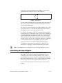
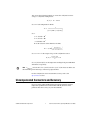
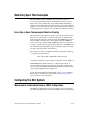
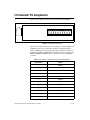
USER GUIDE SCC-TC Series Thermocouple Input Modules The SCC-TC Series thermocouple input modules, SCC-TC01 and SCC-TC02, accept input signals from B-, E-, J-, K-, N-, R-, S-, and T-type thermocouples. The thermocouple inputs are filtered and passed into a differential amplifier with a gain of 100. The output of the amplifier passes through a dual-pole 2 Hz filter. Each module contains thermistor circuitry, powered by a 2.5 V reference, to compensate for cold-junction effects. Each module also can detect open thermocouple circuits. Alternatively, you can connect voltage signals up to ±100 mV to the screw terminals of the SCC-TC02 and use it as a low-bandwidth millivolt-input module. Conventions The following conventions are used in this guide: <> Angle brackets that contain numbers separated by an ellipsis represent a range of values associated with a bit or signal name—for example, ai<0..7>. » The » symbol leads you through nested menu items and dialog box options to a final action. The sequence File»Page Setup»Options directs you to pull down the File menu, select the Page Setup item, and select Options from the last dialog box. This icon denotes a note, which alerts you to important information. This icon denotes a caution, which advises you of precautions to take to avoid injury, data loss, or a system crash. When this symbol is marked on the product, refer to the Read Me First: Safety and Radio-Frequency Interference document, shipped with the product, for precautions to take. When symbol is marked on a product, it denotes a warning advising you to take precautions to avoid electrical shock. When symbol is marked on a product, it denotes a component that may be hot. Touching this component may result in bodily injury. bold Bold text denotes items that you must select in the software, such as menu items and dialog box options. Bold text also denotes parameter names. italic Italic text denotes variables, emphasis, a cross reference, or an introduction to a key concept. This font also denotes text that is a placeholder for a word or value that you must supply. monospace Text in this font denotes text or characters that you should enter from the keyboard, sections of code, programming examples, and syntax examples. This font is also used for the proper names of disk drives, paths, directories, programs, subprograms, subroutines, device names, functions, operations, variables, filenames and extensions, and code excerpts. SC-2345 SC-2345 refers to both the SC-2345 connector block and the SC-2345 configurable connector. SCC SCC refers to any SCC series signal conditioning module. What You Need to Get Started To set up and use the SCC-TC0X, you need the following items: ❑ SC-2345 with one of the following: – SCC-PWR01 – SCC-PWR02 and the PS01 power supply – SCC-PWR03 (requires a 7 to 42 VDC power supply, not included) ❑ One or more SCC-TC0X modules ❑ SCC-TC Series Thermocouple Input Modules User Guide ❑ Read Me First: Safety and Radio-Frequency Interference ❑ SC-2345 User Manual, available online at ni.com ❑ SC-2345 Quick Reference Label ❑ 68-pin E Series DAQ device, documentation, and 68-pin cable ❑ 1/8 in. flathead screwdriver SCC-TC Series Thermocouple Input Modules User Guide 2 ni.com ❑ Numbers 1 and 2 Phillips screwdrivers ❑ Wire insulation strippers ❑ NI-DAQ (current version) for Windows 2000/NT/XP Software scaling of measurements is not supported on the Macintosh operating system. Refer to the Converting Voltage Measurements to Temperature Measurements section for more information about measurement scaling. Note Unpacking the Module SCC modules are shipped in antistatic envelopes to prevent electrostatic damage (ESD) to the modules. ESD can damage several components on these products. Caution Never touch the exposed pins of connectors. To avoid damage from ESD when you handle the module, take the following precautions: • Ground yourself by using a grounding strap or by touching a grounded object. • Touch the antistatic envelope to a metal part of the computer chassis before removing the module from the envelope. Remove the module from the envelope and inspect the module for loose components or any sign of damage. Notify NI if the module appears damaged in any way. Do not install a damaged module. Store the module in the antistatic envelope when it is not in use. Installing the Module Caution Refer to the Read Me First: Safety and Radio-Frequency Interference document before removing equipment covers or connecting/disconnecting any signal wires. © National Instruments Corporation 3 SCC-TC Series Thermocouple Input Modules User Guide A blue stripe on the label identifies the SCC-TC0X as an analog input module. The label also displays the icon shown in Figure 1. TC Figure 1. SCC-TC0X Icon You can plug the SCC-TC0X into any analog input socket on the SC-2345. The socket you select determines which E Series DAQ device channels receive the SCC-TC0X signals. For single-stage input conditioning, plug the SCC-TC0X into any socket J (X +1), where X is 0 to 7, and connect the input signals to the module as described in the Connecting the Input Signals section. If you use the SCC-TC0X in a dual-stage configuration, the SCC-TC0X must be the first-stage module. Plug it into any socket J (X+9) and plug the second-stage SCC into socket J (X+1), where X is 0 to 7. Connect the input signals to SCC-TC0X as described in the Connecting the Input Signals section. The SC-2345 connects the output signals of the first-stage SCC to the inputs of the second-stage SCC. An example of dual-stage conditioning in an SCC-TC0X followed by an SCC-LP01 lowpass filter module. Sockets J9 to J16 also are available for digital input/output (DIO) conditioning or control. Refer to the SC-2345 User Manual for more information on configuring, connecting and installing SCC modules Note SCC-TC0X dual-stage configuration is only available in NI-DAQ 7.1 or later. Connecting the Input Signals The SCC-TC01 has a two-prong uncompensated thermocouple miniconnector that accepts any miniature or subminiature two-prong male thermocouple connector. The SCC-TC02 has a three-position screw-terminal connector that accepts 28 to 16 AWG thermocouple wires. The screw-terminal connector provides a ground connection for shielded thermocouples. Otherwise, the two modules function identically. To use an SCC-TC01, plug the male thermocouple connector into the module. SCC-TC Series Thermocouple Input Modules User Guide 4 ni.com The SCC-TC02 has a fixed screw-terminal receptacle and a removable screw-terminal block, as shown in Figure 2. 1 3 2 1 2 1 SCC Screw-Terminal Receptacle 2 Removable Screw-Terminal Block Figure 2. SCC-TC02 Two-Part Screw-Terminal System After you install the SCC-TC02, attach the input signals to the screw terminals of the module. 1. Remove power from the signal lines. 2. Strip 7 mm (0.28 in.) of insulation from the ends of the signal wires. 3. Insert the wires into the screw terminals. 4. Tighten the screws to 0.5 to 0.6 N ⋅ m (4.4 to 5.3 lb − in.) of torque. The SCC-TC02 accepts up to three signals: TC+, TC–, and GND. TC+ is the positive thermocouple lead and TC– is the negative thermocouple lead.1 The GND terminal connects to AIGND on the E Series DAQ device. The SCC-TC0X has a 10 MΩ bias resistor connected from the negative thermocouple input to ground. This resistor allows the thermocouple to be ground-referenced or floating without requiring external bias resistors connected to ground. 1 For ANSI color-coded J-type thermocouples, the red wire is negative and the white wire is positive. Refer to the thermocouple data sheet if possible. You can find information about other color-coding schemes in the NI KnowledgeBase at ni.com/ support. © National Instruments Corporation 5 SCC-TC Series Thermocouple Input Modules User Guide The amplified thermocouple signal and cold-junction sensor signal are measured by E Series DAQ device channel X and channel X+8 respectively, where X is 0 to 7 depending on where you plug the SCC-TC0X. Refer to Figure 3 for SCC-TC0X signal connections. E Series DAQ Device SCC-TC0X Ref 5 V Thermocouple Source 10 MΩ 10 kΩ 2-Pole Filter/ Buffer Stage + – TC+ 10 kΩ ACH(X ) TCOffset Calibrator 10 MΩ GND (SCC-TC02 only) Ref 5 V AISENSE 4.75 kΩ 1% AIGND LM 4040 2.5 V 0.1% 5 kΩ 0.1% 0.1 µF o -t + 5 kΩ at 25o C 10 µF 16 V 0.1 µF + – ACH(X+8) 2.5 kΩ Figure 3. SCC-TC0X Signal Connections Cold-Junction Sensor Output and Accuracy The cold-junction sensor voltage output varies from 1.91 to 0.58 V over a 0 to 55 °C temperature range. NI-DAQ includes thermistor conversion utilities that implement the equations listed below. Refer to your software documentation for more information on these utilities. Note SCC-TC Series Thermocouple Input Modules User Guide 6 ni.com You can use the following formulas to convert the cold-junction sensor voltage to cold-junction temperature: T ( °C ) = T K – 273.15 where TK is the temperature in kelvin. 1 T K = -------------------------------------------------------------3 [ a + b ( ln R T ) + c ( ln R T ) ] where a = 1.295361 × 10⁻³ b = 2.343159 × 10⁻⁴ c = 1.018703 × 10⁻⁷ RT is the resistance of the thermistor in ohms. V TEMPOUT R T = 5, 000 ------------------------------------ 2.5 – V TEMPOUT where VTEMPOUT is the output voltage of the cold-junction sensor. [ T ( °C ) ]9 T ( °F ) = ------------------------ + 32 5 where T(°F) and T(°C) are the temperature readings in degrees Fahrenheit and Celsius, respectively. VTEMPOUT varies from 1.91 V (at 0 °C) to 0.58 V (at 55 °C). For best resolution, use the maximum gain for this range on the analog input channel. Note For the cold-junction sensor measurement accuracy, refer to the Specifications section. Uncompensated Connectors and Accuracy If you are using an SCC-TC02 with an uncompensated SCC panelette, temperature gradients between the module and the junctions on the panelette affect the accuracy of your measurements. © National Instruments Corporation 7 SCC-TC Series Thermocouple Input Modules User Guide Detecting Open Thermocouples The SCC-TC0X contains a 10 MΩ pull-up resistor that connects to +5 V to detect open thermocouples. To determine if you have an open thermocouple, check whether the corresponding E Series DAQ device channel is saturated. The pull-up and bias resistors saturate the channel by applying +2.5 V at the input of an open channel. This results in saturation to either the positive or negative rails of the E Series DAQ device (±10 V). Errors Due to Open-Thermocouple Detection Circuitry The open-thermocouple detection circuitry can cause measurement errors. These errors are the results of common-mode voltage at the input of the SCC and current leakage into the signal leads. The 10 MΩ bias resistor in the SCC-TC0X causes this error to be negligible. With the 10 MΩ bias resistor connected to ground and the 10 MΩ pull-up resistor connected to +5 VDC, a current leakage of approximately 0.25 µA (5 V/20 MΩ) flows into the unbroken floating thermocouple. Long thermocouple leads result in larger voltage drops due to lead resistance. For example, if you have a 24 AWG J-type thermocouple that is 20 ft long, a voltage drop of approximately 4 µV = (0.145 Ω/ft + 0.658 Ω/ft) × 20 ft × 0.25 µA can develop in the thermocouple, which corresponds to an error of 0.09 °C. With 10 MΩ pull-up and bias resistors, a common-mode voltage of +2.5 VDC develops if the thermocouple is floating. The common-mode rejection of the SCC-TC0X is sufficiently high, which results in the offset voltage being negligible in most applications. If your application demands extremely high accuracy, you can eliminate these errors by calibrating the system. Refer to the Calibrating System Offsets section for more information. Configuring the SCC System Measurement & Automation Explorer (MAX) Configuration Run MAX to configure the SCC system. Complete one of the following procedures depending on the version of NI-DAQ used in your application. SCC-TC Series Thermocouple Input Modules User Guide 8 ni.com NI-DAQmx Complete the following steps to configure the SCC-TC module using NI-DAQmx. 1. Open Measurement & Automation Explorer. 2. Right-click Devices and Interfaces and select Create New. 3. Under NI-DAQmx SCC Connector Block, select SC-2345. Click Finish. 4. In the SCC Connector Block Configuration window, configure the SCC system as follows: 5. a. Specify the SCC Carrier Type. The location of the SCC sockets change depending on the SCC carrier type. b. Select the DAQ Device that is connected to the SC-2345. c. Enter the SCC Connector Block ID. The default value is SCC1. d. In the J21 drop-down list next to Power, select the correct SC-2345 power configuration. Refer to the SC-2345 User Manual for information on power configurations. e. For each SCC module physically installed in the SC-2345, add a corresponding entry in the SC-2345 configuration window. To add the SCC, click the socket drop-down list and select the correct module. If the module name does not appear in the list, either the module is not allowed in that location or you do not have the current version of NI-DAQ. If you do not have the current version of NI-DAQ, download it from ni.com. f. Click OK after completing all SCC entries to complete the configuration process. Close MAX. Note Configuring the SCC system using MAX automatically sets the E Series DAQ device analog input mode to nonreferenced single-ended (NRSE). Traditional NI-DAQ Complete the following steps to configure the SCC-TC module using Traditional NI-DAQ. 1. Open Measurement & Automation Explorer. 2. Expand Devices and Interfaces. 3. Expand Traditional NI-DAQ Devices. 4. Right-click the E Series DAQ device connected to the SC-2345, and select Properties. 5. Select the Accessory tab. © National Instruments Corporation 9 SCC-TC Series Thermocouple Input Modules User Guide 6. Under Accessory:, select SC-2345. 7. Click the Configure button. A new window appears listing the sockets (connector reference designators) of the SC-2345. 8. Select the SC-2345 socket where you installed an SCC. 9. Click Add and select the SCC you installed. If the module name does not appear in the list, either the module is not allowed in that location or you do not have the current version of NI-DAQ. If you do not have the current version of NI-DAQ, download it from ni.com. 10. If you make a selection mistake, select the socket and click Remove. 11. Repeat steps 8 and 9 for each newly installed SCC. 12. Click OK after completing all SCC entries. 13. Click OK to complete the configuration process and close MAX. Configuring the SCC system using MAX automatically sets the E Series DAQ device analog input mode to nonreferenced single-ended (NRSE). Note Virtual Channels, Physical Channels, and Tasks After you have installed and configured your SCC hardware, you can use software tools within MAX to further configure the module and take measurements. Creating an NI-DAQmx Task or Global Channel To create an NI-DAQmx task or global channel, complete the following steps: 1. Open Measurement & Automation Explorer. 2. Right-click Data Neighborhood and select Create New. 3. Select NI-DAQmx Task or NI-DAQmx Global Channel and click Next. 4. Select Analog Input, then select Temperature and then select Thermocouple. 5. If you are creating a task, select the channels to add to the task. You can select blocks of channels by pressing the <Shift> key while making the selections, or select individual channels by pressing the <Ctrl> key while making the selections. If you are creating a channel, you can select only one channel. Click Next. 6. Enter a name for the task or global channel and click Finish. 7. In the Channel List box, select the channel(s) you want to configure. You can select blocks of channels by pressing the <Shift> key while making the selections, or select individual channels by pressing the <Ctrl> key while making the selections. SCC-TC Series Thermocouple Input Modules User Guide 10 ni.com 8. Enter the specific values for your application in the Settings tab. Context help information for each setting is provided on the right side of the screen. 9. Choose the type of thermocouple you have connected to your SCC module. For the CJC Source parameter, select Built-In. 10. Click Test to test the channel. You should be able to view your measurement in the window that appears. You have finished configuring the NI-DAQmx task or global channel. Creating a Virtual Channel in Traditional NI-DAQ To create a Traditional NI-DAQ virtual channel, complete the following steps: 1. Open Measurement & Automation Explorer. 2. Right-click Data Neighborhood and select Create New. 3. Select Traditional NI-DAQ Virtual Channel and click Finish. 4. Click Next to select Analog Input as the type of channel to configure. 5. From the drop-down list, select the appropriate Thermocouple type and click Next. 6. Enter the rest of the values as they apply to your setup and click Next. 7. On the next screen, specify information about the E Series DAQ device being used and the CJC source and click Finish. 8. To test the channel, click Test. You have finished configuring the Traditional NI-DAQ virtual channel. Calibrating System Offsets To calibrate the offset voltage of the SCC-TC0X in the system using the E Series DAQ device, complete the following steps. The E Series DAQ device must be on for 30 minutes before you calibrate the offset voltage. 1. Select the desired channel and gain on the E Series DAQ device. 2. Short the inputs on the SCC-TC0X screw terminals or miniplug. 3. While acquiring data on the selected channel, use a screwdriver to adjust the potentiometer protruding through the top of the module until you read 0 VDC. © National Instruments Corporation 11 SCC-TC Series Thermocouple Input Modules User Guide Calibrating the SCC-TC0X Using a Thermocouple Calibrator To calibrate the system using a thermocouple calibrator, complete the following steps: 1. Make sure that the thermocouple connections at both the SCC and the thermocouple calibrator are at the same temperature. 2. Connect the thermocouple calibrator to the SCC-TC0X. For best results, use thermocouple wire of the same length and type that you use in the thermocouple. 3. Set the thermocouple calibrator to the required calibration temperature. 4. Measure the calibrator voltage using the SCC-TC0X. 5. Convert the measured calibrator voltage to a temperature measurement as described in the Converting Voltage Measurements to Temperature Measurements section. 6. Adjust the potentiometer on the top of the SCC-TC0X so that the measured temperature is equal to the calibration temperature. Converting Voltage Measurements to Temperature Measurements Note NI-DAQ includes thermocouple and thermistor conversion utilities that implement the conversions required in steps 3 and 5 of the following procedure. Refer to your software documentation for more information on these utilities. Your software environment may return only voltage measurements from E Series DAQ devices. If so, you must convert voltage measurements to temperature measurements. To make this conversion, complete the following steps: 1. Measure the thermocouple voltage. a. Read the thermocouple channel on the E Series DAQ device VESERIES [CH(X)]. b. Calculate the thermocouple voltage by using the following formula: V ESERIES V TC = -------------------100 SCC-TC Series Thermocouple Input Modules User Guide 12 ni.com where VTC is thermocouple voltage. VESERIES is E Series DAQ device voltage. This step provides proper scaling for the thermocouple amplifier in the SCC-TC0X. 2. Note Measure the reference-junction (cold-junction) temperature. a. Read the thermistor voltage [ACH(X+8)]. b. Convert the thermistor voltage to cold-junction temperature using the formula in the Cold-Junction Sensor Output and Accuracy section. 3. Calculate the cold-junction compensation voltage by converting the cold-junction temperature you got in step 2 to a thermocouple voltage. Use the polynomial expressions applicable to the type of thermocouple you are using. 4. Apply the cold-junction compensation to the thermocouple reading by adding the cold-junction compensation voltage you got in step 3 to VTC . 5. Calculate the thermocouple temperature by converting the voltage result you got in step 4 to a temperature. Use the polynomial expressions applicable to the type of thermocouple you are using. This calculation gives you a linearized temperature measurement. Polynomials come from NIST Monograph 175. Specifications These specifications are typical at 25 °C unless otherwise stated. Analog Input Number of input channels ...................... 1 DIFF Input signals ........................................... Thermocouples of types B, E, J, K, N, R, S, and T Input signal range................................... ±100 mV Input impedance..................................... 10 MΩ powered on, 10 kΩ powered off or overload Bandwidth .............................................. 2 Hz © National Instruments Corporation 13 SCC-TC Series Thermocouple Input Modules User Guide Amplifier Characteristics Open thermocouple detection current.....250 nA max1 (assuming floating thermocouple) Common-mode rejection ratio................110 dB min1 Output range ...........................................±10 V max1 Transfer Characteristics Gain ........................................................100 Gain error................................................±0.08% max1 Gain stability...........................................±0.0005%/°C max2 Offset error .............................................±5 µV max (post calibration)1 Offset stability ........................................±0.6 µV/°C max2 Nonlinearity ............................................±0.004% max1 Recommended warm-up time.................5 minutes Measurement Accuracy 3 1 2 3 Thermocouple Type Temperature Range (°C) Maximum Inaccuracy (±°C) Typical Inaccuracy (±°C) B 400 to 600 600 to 1,800 2.5 2 0.31 0.13 E –200 to –100 –100 to 600 600 to 1,000 2 1 1.5 1.76 1 0.6 J –200 to –100 –100 to 500 500 to 1,100 2 1 1.5 1.6 0.9 0.72 Temperature range is 23 °C ±5 °C. Temperature range is 0 to 50 °C. Total system measurement error for operating temperature within ±5 °C of calibration temperature. Includes PCI/AT-MIO-16XE-50 one-year accuracy specification of 0.01% ±412 µV. SCC-TC01/02 accuracy specification of 0.08% ±5 µV, and reference junction measurement accuracy of 0.5 °C. Assumes averaging. Non-averaged, single-point reading has an additional uncertainty (up to ±0.1 °C for J-type thermocouple). SCC-TC Series Thermocouple Input Modules User Guide 14 ni.com Thermocouple Type Temperature Range (°C) Maximum Inaccuracy (±°C) Typical Inaccuracy (±°C) K –200 to –100 –100 to 600 600 to 1,200 2.5 1.25 2 1.25 0.67 0.45 N –200 to –100 –100 to 1,300 2.5 2 2 0.7 R –50 to 0 0 to 100 100 to1,600 3 2 1.75 1.24 0.82 0.4 S –50 to 0 0 to 1,400 1,400 to 1,600 3 2 2.5 1.3 1 1 T –200 to –100 –100 to 400 2.5 1 2 0.9 Cold-Junction Sensor Cold-junction sensor accuracy ............... ±0.4 °C max from 15 to 35 °C, ±0.75 °C max from 0 to 15 °C and 35 to 55 °C Output..................................................... 1.91 V (0 °C) to 0.58 V (55 °C) Note The accuracy specification includes the combined effects of the temperature sensor accuracy and the temperature difference between the temperature sensor and any thermocouple connector. The temperature sensor accuracy includes component tolerances, temperature drifts, and self-heating effects. It does not include measurement device errors. Open Thermocouple Detection Pull-up resistor ....................................... 10 MΩ Bias resistor............................................ 10 MΩ Maximum field wire gauge .................... 16 AWG Power Requirement Analog power ......................................... 60 mW max +15 V .............................................. 2 mA max –15 V............................................... 2 mA max Digital power (+5 V).............................. 0.0 mW © National Instruments Corporation 15 SCC-TC Series Thermocouple Input Modules User Guide Physical TC01 dimensions ....................................7.8 cm by 2.92 cm by 1.85 cm (3.1 in. by 1.15 in. by 0.73 in.) TC02 dimensions ....................................8.89 cm by 2.92 cm by 1.85 cm (3.50 in. by 1.15 in. by 0.73 in.) I/O ...........................................................One 20-pin right angle male connector, 3-pin screw terminal system (SCC-TC02); two-prong mini-connector (SCC-TC01) Screw terminal field-wiring gauge (SCC-TC02) .................................28 to 16 AWG Maximum Working Voltage Maximum working voltage refers to the signal voltage plus the common-mode voltage. Each input must remain within ±12 V of chassis ground. Installation Category I Environmental Operating temperature ............................0 to 50 °C Storage temperature ................................–20 to 70 °C Humidity .................................................10 to 90% RH, noncondensing Maximum altitude...................................2,000 m Pollution Degree (indoor use only) ........2 Safety The SCC-TC0X meets the requirements of the following standards for safety and electrical equipment for measurement, control, and laboratory use: • IEC 61010-1, EN 61010-1 • UL 3111-1, UL 61010B-1 • CAN/CSA C22.2 No. 1010.1 SCC-TC Series Thermocouple Input Modules User Guide 16 ni.com Note For UL and other safety certifications, refer to the product label, or visit ni.com/hardref.nsf, search by model number or product line, and click the appropriate link in the Certification column. Electromagnetic Compatibility Electrical emissions................................ EN 55011 Class A at 10 m FCC Part 15A above 1 GHz Electrical immunity................................ Evaluated to EN 61326:1997/ A2:2001, Table 1 CE, C-Tick, and FCC Part 15 (Class A) Compliant For full EMC compliance, you must operate this device with shielded cabling. In addition, all covers and filler panels must be installed. Note CE Compliance The SCC-TC0X meets the essential requirements of applicable European Directives, as amended for CE marking, as follows: Low-Voltage Directive (safety) ............. 73/23/EEC Electromagnetic Compatibility Directive (EMC) .................................... 89/336/EEC Refer to the Declaration of Conformity (DoC) for this product for any additional regulatory compliance information. To obtain the DoC for this product, visit ni.com/hardref.nsf, search by model number or product line, and click the appropriate link in the Certification column. Note © National Instruments Corporation 17 SCC-TC Series Thermocouple Input Modules User Guide I/O Connector Pin Assignments Figure 4 shows the I/O connector pins on the bottom of the module. 19 3 17 15 13 11 9 7 5 3 1 20 18 16 14 12 10 8 6 4 2 Figure 4. SCC Module Bottom View Table 1 lists the signal connection corresponding to each pin. ACH(X) and ACH(X+8) are the analog input signal channels of the E Series DAQ device. AIGND is the analog input ground signal and is the reference for ACH(X) and ACH(X+8). AGND is the reference for the ±15 V supplies and REF5V. AIGND and AGND connect to the SC-2345 at the SCC-PWR connector. Table 1. SCC Module Pin Signal Connections for SCC-TC0X Modules Pin Number Signal 1 ACH(X) 2 — 3 — 4 ACH(X+8) 5 — 6 AIGND 7 — 8 — 9 — 10 — 11 AGND 12 REF5V SCC-TC Series Thermocouple Input Modules User Guide 18 ni.com Table 1. SCC Module Pin Signal Connections for SCC-TC0X Modules (Continued) © National Instruments Corporation Pin Number Signal 13 +15 V 14 –15 V 15 — 16 — 17 — 18 — 19 — 20 — 19 SCC-TC Series Thermocouple Input Modules User Guide National Instruments™, NI™, ni.com™, and NI-DAQ™ are trademarks of National Instruments Corporation. Product and company names mentioned herein are trademarks or trade names of their respective companies. For patents covering National Instruments products, refer to the appropriate location: Help»Patents in your software, the patents.txt file on your CD, or ni.com/patents. © 2002–2003 National Instruments Corp. All rights reserved. *323099B-01* 323099B-01 Sep03