1
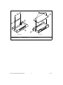
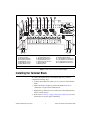
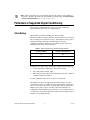
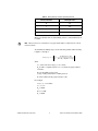
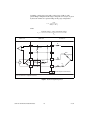
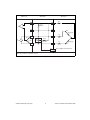
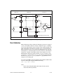
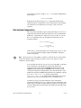
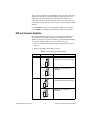
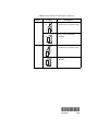
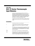
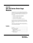
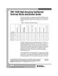
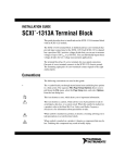
SCXI™-1321 OFFSET-NULL AND
SHUNT-CALIBRATION HIGH-VOLTAGE
TERMINAL BLOCK INSTALLATION GUIDE
This guide describes how to install and use the SCXI-1321 offset-null
and shunt-calibration terminal block with the SCXI-1121 module. You can
only use the SCXI-1321 terminal block with SCXI-1121 revision C or later
modules. In addition to the 18 screw terminals, the SCXI-1321 has circuitry
for offset-null adjustment of Wheatstone bridges, and a socketed shunt
resistor for strain-gauge shunt calibration. This terminal block was
primarily designed for Wheatstone bridge transducers such as strain
gauges, although it can easily accommodate thermocouples, RTDs,
thermistors, millivolt sources, volt sources, and current-loop receivers.
Thermocouples have cold-junction compensation (CJC) support.
Conventions
The following conventions are used in this guide:
»
The » symbol leads you through nested menu items and dialog box options
to a final action. The sequence File»Page Setup»Options directs you to
pull down the File menu, select the Page Setup item, and select Options
from the last dialog box.
This icon denotes a note, which alerts you to important information.
This icon denotes a caution, which advises you of precautions to take to
avoid injury, data loss, or a system crash. When this symbol is marked on
the product, refer to the Read Me First: Safety and Radio-Frequency
Interference document, shipped with the product, for precautions to take.
bold
Bold text denotes items that you must select or click in the software, such
as menu items and dialog box options. Bold text also denotes parameter
names.
LabVIEW™, National Instruments™, NI™, ni.com™, NI-DAQ™, and SCXI™ are trademarks of National Instruments
Corporation. Product and company names mentioned herein are trademarks or trade names of their respective
companies. For patents covering National Instruments products, refer to the appropriate location: Help»Patents in your
software, the patents.txt file on your CD, or ni.com/patents.
ni.com
© 1998–2003 National Instruments Corp. All rights reserved.
January 2003
321924C-01
italic
Italic text denotes variables, emphasis, a cross reference, or an introduction
to a key concept. This font also denotes text that is a placeholder for a word
or value that you must supply.
monospace
Text in this font denotes text or characters that you should enter from the
keyboard, sections of code, programming examples, and syntax examples.
This font is also used for the proper names of disk drives, paths, directories,
programs, subprograms, subroutines, device names, functions, operations,
variables, filenames and extensions, and code excerpts.
monospace italic
Italic text in this font denotes text that is a placeholder for a word or value
that you must supply.
What You Need to Get Started
To set up and use the SCXI-1321, you need the following items:
❑ SCXI-1321 offset-null and shunt-calibration terminal block
❑ SCXI-1321 Offset-Null and Shunt-Calibration High-Voltage
Terminal Block Installation Guide Installation Guide
❑ Read Me First: Safety and Radio-Frequency Interference
❑ SCXI chassis and documentation
❑ SCXI-1121 module (revision C or later) and documentation
❑ Numbers 1 and 2 Phillips screwdrivers
❑ 1/8 in. flathead screwdriver
❑ Long-nose pliers
❑ Wire cutter
❑ Wire insulation stripper
SCXI-1321 Terminal Block Installation Guide
2
ni.com
Connecting the Signals
Refer to the Read Me First: Safety and Radio-Frequency Interference document
before removing equipment covers, or connecting or disconnecting any signal wires.
Note
To connect the signal to the terminal block, complete the following steps,
referring to Figure 1 as necessary:
1.
Unscrew the top-cover screws and remove the cover.
2.
Loosen the strain-relief screws and remove the strain-relief bar.
3.
Enable or bypass each of the nulling circuits, depending on the signal
you are measuring.
Disable the offset-nulling circuitry when you are not using a Wheatstone bridge or
when the excitation channel of the SCXI-1121 is in current mode.
Note
4.
Run the signal wires through the strain-relief opening. You can add
insulation or padding if necessary.
5.
Prepare the signal wire by stripping the insulation no more than 7 mm
(0.28 in.).
6.
Connect the wires to the screw terminals by inserting the stripped end
of the wire fully into the terminal. No bare wire should extend past the
screw terminal. Exposed wire increases the risk of a short circuit and a
hardware failure.
7.
Tighten the screws to a torque of 0.57 to 0.79 newton-m (5 to 7 lb-in.).
8.
Connect safety earth ground to the safety-ground lug. Refer to the
Read Me First: Safety and Radio-Frequency Interference document
for connection information.
9.
Reinstall the strain-relief bar, and tighten the strain-relief screws.
10. Reinstall the top cover, and tighten the top-cover screws.
11. Connect the terminal block to the module front connector as explained
in the Installing the Terminal Block section.
© National Instruments Corporation
3
SCXI-1321 Terminal Block Installation Guide
6
2
7
3
1
4
5
Back View
1
2
Strain-Relief Bar
Strain-Relief Screws
3
4
Front View
Safety-Ground Lug
Mating Connector
5
6
Thumbscrew
Top-Cover Screws
7
Top Cover
Figure 1. SCXI-1321 Parts Locator Diagram
SCXI-1321 Terminal Block Installation Guide
4
ni.com
5
3
6
7
8
9
10
11
12
4
2
13
14
15
16
1
20
1
2
3
4
5
6
7
19
18
Screw Terminals
Product Information
W1 (CH0 Null Enabled)
W2 (CH1 Null Enabled)
R3 (CH0 Null Resistor)
R4 (CH0 Shunt Resistor)
R5 (CH1 Null Resistor)
8
9
10
11
12
13
14
R6 (CH1 Shunt Resistor)
R7 (CH2 Null Resistor)
R8 (CH2 Shunt Resistor)
R9 (CH3 Null Resistor)
R10 (CH3 Shunt Resistor)
W5 (CJC Mode)
Warning Label
15
16
17
18
19
20
17
W4 CH3 Null Enabled)
W3 (CH2 Null Enabled)
R15 (CH3 Null Potentiometer)
R14 (CH2 Null Potentiometer)
R2 (CH1 Null Potentiometer)
R1 (CH0 Null Potentiometer)
Note: R3 through R10 are socketed.
Figure 2. SCXI-1321 Circuit Parts Locator Diagram
Installing the Terminal Block
To connect the terminal block to the SCXI module front connector,
complete the following steps:
1.
Connect the module front connector to its connector on the terminal
block.
2.
Make sure that the module top and bottom thumbscrews do not
obstruct the rear panel of the terminal block.
3.
Tighten the top and bottom screws on the back of the terminal block to
hold it securely in place.
4.
Refer to the Performed or Supported Signal Conditioning section for
information on specific signal conditioning.
© National Instruments Corporation
5
SCXI-1321 Terminal Block Installation Guide
To minimize the temperature gradient inside the terminal block, move the SCXI
chassis away from any extreme temperature differential.
Note
Specifications
All specifications are typical at 25 °C unless otherwise specified.
Electrical
Cold-junction sensor
Accuracy1 ........................................0.9 °C
Output ..............................................10 mV/°C from 0 to 55 °C
Resistors
RSHUNT .............................................301 kΩ ±1%
RNULL ...............................................39 kΩ ±5%
RTRIM ...............................................10 kΩ
Nulling potentiometer
Range...............................................0 to 10 kΩ
Step size...........................................infinite (user adjustable)
Mechanical
Resistor sockets
Connecting lead size........................0.023 to 0.026 in.
Connecting lead length ....................0.110 to 0.175 in.
Lead spacing....................................0.500 in.
Maximum Working Voltage
Maximum working voltage refers to the signal voltage plus the
common-mode voltage.
Channel-to-earth .....................................300 V, Installation Category II
Channel-to-channel.................................300 V, Installation Category II
1
The temperature sensor accuracy includes tolerances in all component values caused by temperature and loading,
and self-heating.
SCXI-1321 Terminal Block Installation Guide
6
ni.com
Environmental
Operating temperature............................ 0 to 50 °C
Storage temperature ............................... –20 to 70 °C
Humidity ................................................ 10 to 90% RH, noncondensing
Maximum altitude .................................. 2,000 meters
Pollution Degree (indoor use only) ........ 2
Safety
The SCXI-1321 is designed to meet the requirements of the following
standards of safety for electrical equipment for measurement, control and
laboratory use:
Note
•
IEC 61010-1, EN 61010-1
•
UL 3111-1, UL61010B-1
•
CAN/CSA C22.2 No. 1010.1
For UL and other safety certifications refer to the product label or to ni.com.
Electromagnetic Compatibility
Emissions ............................................... EN 55011 Class A at 10 meters;
FCC Part 15A above 1 GHz
Immunity................................................ EN 61326:1997 + A2:2001,
Table 1
EMC/EMI............................................... CE, C-Tick and FCC Part 15
(Class A) Compliant
Note
For EMC compliance, operate this device with shielded cabling.
CE Compliance
The SCXI-1321 meets the essential requirements of applicable European
Directives, as amended for CE Marking, as follows:
Low-Voltage Directive (safety) ............. 73/23/EEC
Electromagnetic Compatibility Directive (EMC)89/336/EEC
© National Instruments Corporation
7
SCXI-1321 Terminal Block Installation Guide
Refer to the Declaration of Conformity (DoC) for this product for any additional
regulatory compliance information. To obtain the DoC for this product, click Declarations
of Conformity Information at ni.com/hardref.nsf/.
Note
Performed or Supported Signal Conditioning
This section provides information on types of signal conditioning
performed by the SCXI-1321 or is supported by it.
Offset Nulling
Offset nulling is a hardware nulling procedure used with
Wheatstone-bridge transducers that have an initial offset error. Correcting
this error improves measurement accuracy. The nulling circuitry operates
with quarter-bridge, half-bridge, and full-bridge strain-gauge
configurations. Each channel has its own nulling circuitry and its own
trimming potentiometer as listed in Table 1.
Table 1. Trimmer Potentiometers and Corresponding Channels
Channel Number
Trimmer Potentiometer
0
R1
1
R2
2
R14
3
R15
To null the static offset voltage of the bridge, complete the following steps:
1.
Connect the bridge configuration to the selected channel.
2.
Select and read the channel output.
3.
While monitoring the output, rotate the trimmer wiper with a flathead
screwdriver until you reach 0 V.
You have nulled the bridge and are ready for a measurement.
The nulling range that is provided with the terminal block is ±2.5 mV,
assuming that you have a 120 Ω strain gauge quarter-bridge configuration
and 3.3 V excitation voltage. You can change this range by replacing the
nulling resistor with a resistor of another value. Each channel has an
independent socketed nulling resistor. Therefore, you can mix the ranges to
accommodate each channel requirement. Table 2 lists the nulling resistors
and their corresponding channels.
SCXI-1321 Terminal Block Installation Guide
8
ni.com
Table 2. Nulling Resistors and Corresponding Channels
Channel Number
Nulling Resistor
0
R3
1
R5
2
R7
3
R9
The factory default value of all the nulling resistors on the terminal block
is 39 kΩ.
These resistors are socketed for easy replacement. These sockets best fit a 1/4 W
resistor lead size.
Note
To determine the nulling range, use the following formula while referring
to Figures 3 through 5:
V exc
V exc R d ( R null + R g )
V nulling range = ± --------- – ---------------------------------------------------------2
R null R g + R d ( R null + R g )
where
Vexc is the excitation voltage (3.3 V or 10 V)
Rd is either a completion resistor or a second strain-gauge nominal
resistance
Rnull is the nulling resistor value
(range of trim potentiometer + nulling resistor)
Rg is the nominal strain-gauge resistance value
For example,
Vnulling range = ±2.56 mV
Vexc = 3.3 V
Rd = 120 Ω
Rnull = 39 kΩ
Rg = 120 Ω
© National Instruments Corporation
9
SCXI-1321 Terminal Block Installation Guide
Assuming a strain-gauge range with a gauge factor of GF = 2 and a
quarter-bridge configuration, this range corresponds to ±1,498 µε, as given
by the strain formula for a quarter-bridge strain-gauge configuration:
– 4V r
ε = ------------------------------GF ( 1 + 2V r )
where
strained voltage – static unstrained voltage
V r = -------------------------------------------------------------------------------------------------------V exc
SCXI-1121
SCXI-1321
Transducer
RL
CH+
CH+
RSCAL
+
301 kΩ
–
VEX
+
–
R1
CH–
CH–
EX+
EX+
4.5 kΩ
4.5 kΩ
RTrim
10 kΩ
R2
EX+
R4(gauge)
RL
RNull
CH+
39.1 kΩ
RL
EX–
EX–
R3(dummy)
RTrim
(Screw Adjusts Potentiometer)
Note: R1 and R2 are completion resistors.
Figure 3. Quarter-Bridge Nulling Circuit
SCXI-1321 Terminal Block Installation Guide
10
ni.com
SCXI-1121
SCXI-1321
Transducer
RL
CH+
CH+
RSCAL
+
301 kΩ
–
VEX
+
–
R1
CH–
CH–
EX+
EX+
4.5 kΩ
R2
4.5 kΩ
RTrim
10 kΩ
EX+
R4(gauge)
RL
RNull
CH+
39.1 kΩ
RL
EX–
EX–
RTrim
R3(gauge)
EX–
(Screw Adjusts Potentiometer)
Note: R1 and R2 are completion resistors.
Figure 4. Half-Bridge Nulling Circuit
© National Instruments Corporation
11
SCXI-1321 Terminal Block Installation Guide
SCXI-1121
SCXI-1321
Transducer
RL
CH+
CH+
RSCAL
+
301 kΩ
–
RL
CH–
CH–
EX+
EX+
VEX
+
RTrim
10 kΩ
–
RL
EX+
R4
(gauge)
CH– CH+
RNull
39.1 kΩ
R1
(gauge)
RL
R2
(gauge)
R3
(gauge)
EX–
EX–
RTrim
(Screw Adjusts Potentiometer)
Figure 5. Full-Bridge Nulling Circuit
Shunt Calibration
Shunt calibration provides a method of adjusting for gain error to improve
accuracy. The shunt-calibration circuitry configuration places a shunting
resistor in parallel with the resistive element connected between EX+ and
CH+ (element R4) of the Wheatstone bridge gauge, as shown in Figure 5.
Shunt calibration circuits of each channel are independent from each other,
although they are controlled together in software; therefore, when SCAL is
engaged on a channel, all the shunt switches of the channels are closed.
When SCAL is disengaged, all the switches are open. At startup or reset,
all switches are open by default. You can control SCAL with the NI-DAQ
function SCXI_Calibrate_Setup. Set the Cal_Op parameter to 2 for
engaged or 0 for disengaged.
You can use LabVIEW to take measurements from channels with the shunt
resistors connected by using the SCXI channel string
obx ! scy ! mdz ! shuntw.
where
x is the onboard channel number (0 for single chassis systems)
y is the chassis ID (1 by default)
SCXI-1321 Terminal Block Installation Guide
12
ni.com
z is the module slot of the SCXI-1121
w is the channel of the module that you want to engage the shunt and
take measurements
For example, if you want to measure the voltage at channel 0 with the shunt
resistor enabled, use the SCXI channel string
ob0 ! sc1 ! md1 ! shunt0.
You also can specify a list of channels by using
ob0 ! sc1 ! md1 ! shunt0:w, for example. Refer to the LabVIEW
Measurements Manual for information on using SCXI channel strings.
The shunting resistors RSCAL are socketed so that you can replace them with
a resistor of another value to achieve the required nulling range for your
application. The sockets and corresponding channels are shown in Table 3.
The factory installed RSCAL provided on the terminal block have a 301 kΩ
±1% value.
Table 3. Socket to Channel Relationship
Channel
Shunt Resistor Socket
0
R4
1
R6
2
R8
3
R10
Assuming a quarter-bridge strain-gauge configuration with a gauge factor
of GF = 2, the equivalent strain change introduced by the RSCAL shunting
resistor is –199 µε.
Refer to the Traditional NI-DAQ User Manual for more information on
strain-gauge bridge configurations and formulas.
Use the following formula to determine the change due to this shunting
resistor:
V ex R d ( R SCAL + R g )
V ex
V change = ---------------------------------------------------------------- – ------R g R SCAL + R d ( R SCAL + R g ) 2
Next, using the appropriate strain-gauge strain formula, and assuming that
you have no static voltage, determine the equivalent strain the RSCAL should
provide. For example, RSCAL = 301 kΩ and a quarter-bridge 120 Ω strain
© National Instruments Corporation
13
SCXI-1321 Terminal Block Installation Guide
gauge with a gauge factor of GF = 2, Vexc = 3.3 V, and R = 120 Ω produces
the following:
Vchange = 0.3321 mV
Replacing the strained voltage by Vchange in the quarter-bridge strain
equation produces an equivalent 199 µε of change. Refer to the NI-DAQ
User Manual for more information on voltage to strain conversion
equations.
Cold-Junction Compensation
CJC is used only with thermocouples and provides improved accuracy of
temperature measurements. The CJC temperature sensor, mounted in the
SCXI-1321, outputs 10 mV/°C and has an accuracy of ±0.9 °C over the
0 to 55 °C temperature range. To determine the temperature, use the
following formulas:
T (°C) = 100 × V TEMPOUT
(°C) × 9- + 32
T (°F) = T
-----------------------5
where VTEMPOUT is the temperature sensor output voltage, and T (°F) and
T (°C) are the temperature readings in degrees Fahrenheit and degrees
Celsius, respectively.
Use the average of a large number of samples to obtain the most accurate reading.
Noisy environments require averaging for greater accuracy. You cannot use virtual
channels to take the readings.
Note
You can enable the CJC sensor in one of two ways depending on the input
mode configuration of the SCXI-1121. Jumper W5 switches the
temperature sensor output between MTEMP (multiplexed mode) and
DTEMP (parallel mode) modes. In MTEMP mode, you must scan the
cold-junction temperature independently of the other AI channels on the
SCXI-1121 using the LabVIEW Getting Started Analog Input VI, available
in examples\daq\run_me.llb, with the channel string
ob0 ! sc1 ! md1 ! mtemp. This reads the temperature sensor on the
terminal block connected to the module in slot 1 of SCXI chassis 1.
You then can average several measurements of the cold-junction
temperature and use this average to compensate for the cold junction of the
thermocouple. Using this averaging method compensates for temperature
variations during the measurement period and makes the CJC temperature
more accurate.
SCXI-1321 Terminal Block Installation Guide
14
ni.com
You can read a temperature at the beginning of the test and use that value
with the data that follows. Using this method assumes that there are no
temperature variations during the measurement period. If there are
temperature variations, the measurements can be less accurate. You also
can read the cold-junction temperature once per scan of the thermocouple
channels.
Use the DTEMP mode if you are operating the SCXI-1121 in parallel
mode. DTEMP uses CH4 analog input, therefore CH3 is not available.
RTD and Thermistor Excitation
By properly setting the excitation, you can configure the SCXI-1321 on
a per channel basis for RTD and thermistor measurements. With the
SCXI-1121 excitation set in the current mode, you must disable the nulling
circuit of the channel of interest. You can do this in two steps:
1.
Place the enable/disable jumper in position D (disable) as shown in
Table 4.
2.
Remove the nulling resistor from its sockets.
Table 4. Jumper Settings of the Nulling Circuits
Jumper
Position
W1
Description
Nulling circuit of Channel 0
is enabled (factory default setting)
D
E
Nulling circuit of Channel 0
is disabled
D
E
W2
D
Nulling circuit of Channel 1
is enabled (factory default setting)
E
D
Nulling circuit of Channel 1
is disabled
E
© National Instruments Corporation
15
SCXI-1321 Terminal Block Installation Guide
Table 4. Jumper Settings of the Nulling Circuits (Continued)
Jumper
Position
W3
Description
Nulling circuit of Channel 2
is enabled (factory default setting)
D
E
Nulling circuit of Channel 2
is disabled
D
E
W4
D
Nulling circuit of Channel 3
is enabled (factory default setting)
E
D
Nulling circuit of Channel 3
is disabled
E
*321924C-01*
321924C-01
Jan03