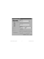
1
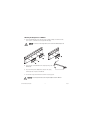
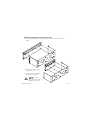
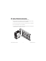
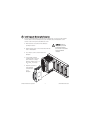
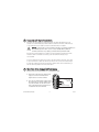
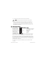
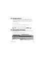
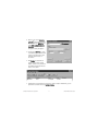
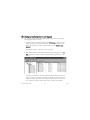
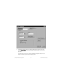
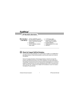
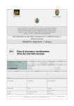
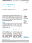
FieldPoint
TM
cFP-20xx Quick Start Guide
What You Need
to Get Set Up
• cFP-20xx LabVIEW RT controller
• Mounting hardware (DIN rail, panelmount, or rack-mount accessory)
• I/O module(s)
• Connectivity accessories: connector
blocks, cables
• 11–30 V power supply
• Accessories: Ethernet cable,
screwdriver
• PC running Windows
• FieldPoint software 3.0.2 or later
• LabVIEW RT
Mount the Compact FieldPoint Backplane
1
You can mount the cFP-BP-x backplane on a 35 mm DIN rail, on a panel, or in a standard 19 in. rack.
Before using any of these mounting methods, record the serial number from the back of the backplane.
Cabling
Clearance
Min. 165 mm [6.50 in.]
4 slots = 246 mm (9.68 in.)
8 slots = 441 mm (17.4 in.)
Cooling Outline
50.8 mm [2.00 in.]
© National Instruments Corporation
Cooling Outline
50.8 mm [2.00 in.]
1
127 mm [5.00 in.]
4 slots = 246 mm (9.68 in.)
8 slots = 441 mm (17.4 in.)
106 mm [4.18 in.]
Min. 182 mm [7.18 in.]
CAUTION Keep in mind these requirements for space and cabling clearance:
• Allow at least 51 mm (2 in.) all around the backplane for air circulation.
• Allow 38 mm (1.5 in.) below the controller for cabling clearance.
Cabling
Clearance
Cooling Outline
51–76 mm [2–3 in.]
All Around
cFP-20xx Quick Start Guide
Mounting the Backplane on a DIN Rail
A. Fasten the DIN rail clip(s) to the cFP-BP-x using a number 2 Phillips screwdriver and the
8-32 × 5/16 in. countersink screws shipped with the clip(s).
CAUTION Do not use screws longer than 5/16 in. to fasten the DIN rail clip to the
backplane.
L
NA S
TIO ENT
NATRUM
INS
L
NA S
TIO ENT
NATRUM
INS
B. Insert one edge of the DIN rail into the deeper opening of the
DIN rail clip.
C. Press down firmly on the backplane to compress the spring
until the clip locks in place on the DIN rail.
D. Connect the PE ground terminal on the cFP-BP-x to safety ground.
CAUTION Disconnect power before removing the backplane from the DIN rail.
cFP-20xx Quick Start Guide
2
ni.com
Mounting the Backplane on a Panel
L
NA TS
TIO EN
NATRUM
INS
A. Fasten the panel-mount plates to the back of the
cFP-BP-x using a number 2 Phillips screwdriver and
the 8-32 × 5/16 in. countersink screws shipped with
the kit.
102 mm (4 in.)
CAUTION Do not use screws longer than
5/16 in. to fasten the panel-mount plates to
the backplane.
457 mm (18 in.)
C. Connect the PE ground terminal
on the cFP-BP-x to safety ground.
CAUTION Disconnect
power before removing the
backplane from the panel.
© National Instruments Corporation
102 mm (4 in.)
B. Bolt or screw the panel-mount
accessory to a panel.
260 mm (10.25 in.)
3
cFP-20xx Quick Start Guide
Mounting the Backplane in a Standard 19-in. Rack
A. Fasten the rack-mount bracket to the back of the cFP-BP-x using the captive screws on the
bracket.
L
NA TS
TIO EN
NATRUM
INS
L
NA TS
TIO EN
NATRUM
INS
B. Bolt the rack-mount accessory to a
standard 19-in. rack.
C. Connect the PE ground terminal on
the cFP-BP-x to safety ground.
CAUTION Disconnect
power before removing the
backplane from the panel.
cFP-20xx Quick Start Guide
4
ni.com
2
Install the cFP-20 xx Controller on the Backplane
A. Make sure that no power is connected to the controller or the backplane.
B. Make sure that the cFP-20xx controller is right side up with the NI logo at the top, and align
the captive screws on the controller with the holes on the backplane.
C. Seat the card edge at the back of the controller in the card-edge connector on the backplane.
D. Press the controller firmly to seat it on the backplane.
E. Using a number 2 Phillips screwdriver with a shank of at least 64 mm (2.5 in.) length, tighten
the captive screws to 1.1 N ⋅ m (10 lb ⋅ in.) of torque.
NAT
INST
IO
RUNAL
MEN
TS
© National Instruments Corporation
5
cFP-20xx Quick Start Guide
3
Install I/O Modules on the Backplane
A. Align the captive screws on the I/O module with the holes on the backplane.
B. Press firmly to seat the I/O module on the backplane.
C. Using a number 2 Phillips screwdriver with a shank of at least 64 mm (2.5 in.) length, tighten
the captive screws to 1.1 N ⋅ m (10 lb ⋅ in.) of torque.
D. Repeat this procedure to install additional I/O modules on the backplane.
cFP-20xx Quick Start Guide
6
ni.com
4
Install Connector Blocks on the Backplane
In order to connect I/O modules to input signals or to external loads, you need to install a cFP-CB-x
connector block or other connectivity accessory for each I/O module on the backplane. Use the
connector socket to the right of each I/O module socket.
A. Wire field devices as described in the I/O module
operating instructions.
B. Align the captive screws on the connector block with the
holes on the backplane.
C. Press firmly to seat the connector block on the
backplane.
CAUTION Hazardous
voltage wiring should be
performed by qualified
personnel and in accordance
with local electrical
standards.
D. Using a number 2 Phillips
screwdriver with a shank of at
least 64 mm (2.5 in.) length,
tighten the captive screws to 1.1
N ⋅ m (10 lb ⋅ in.) of torque.
E. Repeat this procedure to
install additional
connector blocks
on the
backplane.
© National Instruments Corporation
7
cFP-20xx Quick Start Guide
5
Connect the cFP-20xx to Your Network
Connect the cFP-20xx controller to an Ethernet network using the RJ-45 Ethernet port on the
controller. Use a standard Category 5 Ethernet cable to connect the cFP-20xx to an Ethernet hub,
or use an Ethernet crossover cable to connect the controller directly to a computer.
CAUTION To prevent data loss and to maintain the integrity of your Ethernet installation, do
not use a cable longer than 100 m. If you are using a 100 Mbps Ethernet, National
Instruments recommends using a Category 5 shielded twisted-pair Ethernet cable.
If the host PC is already configured on a network, you must configure the cFP-20xx on the same
network. If neither is connected to a network, you can connect the two directly using a
crossover cable.
In order to configure the cFP-20xx, it must reside on the same subnet as the host PC. If you want
to use the cFP-20xx on a subnet other than the one the host PC is on, first connect and configure
it on the same subnet as the host PC, then reassign a static IP address for the subnet where you
want it to be and physically move it to the other subnet.
6
Wire Power to the Compact FieldPoint System
Each cFP-20xx on your network requires an 11–30 VDC power supply.
A. Connect the positive lead of the primary power
supply to one of the V1 terminals and the
negative lead to one of the C terminals.
B. If you are using a backup power supply, connect
the positive lead to V2 and the negative lead to
one of the C terminals. The cFP-20xx uses the
power supply with the higher voltage level. V2
is isolated from the other V terminals.
cFP-20xx Quick Start Guide
8
C
V1
11–30 VDC Backup
Power Supply
(optional)
–
+
–
+
11–30 VDC
Primary Power Supply
V2
ni.com
C. Use a separate power supply for each module that needs external power.
CAUTION Cascading power defeats isolation between the cascaded modules.
D. Refer to the operating instructions for the power requirements of each I/O module. If a
module requires external power, connect a power supply to the V and C inputs on the
connector block for that module. If you want to power field I/O devices from a connector
block, supply power to the connector block, and then connect the connector block V and C
output terminals to the field device.
7
Powering Up the cFP-20xx
ON
1 2 3 4 5 6 7 8
Check the DIP switches on
DIP Switches Functions
the controller, making sure
1, 2 . . . . . . . . . .User-configurable on cFP-2000 and
that the RESET IP switch is
cFP-2010; disabled on cFP-2020
not enabled. Plug in each
3,
4,
5
.
.
.
.
.
.
.
.User-configurable
power supply to the Compact
6 . . . . . . . . . . . .DISABLE VI
FieldPoint system. The
cFP-20xx runs a power-on
7 . . . . . . . . . . . .SAFE MODE
self test (POST) that takes
8 . . . . . . . . . . . .RESET IP
several seconds. You should
see the POWER and STATUS LEDs come on. After about five seconds, the STATUS LED begins
flashing. The cFP-20xx is ready to be configured, and you can install the FieldPoint software.
If you have already assigned an IP address to the cFP-20xx, the STATUS LED turns off, and the
A, B, C, and D LEDs come on for about 15 seconds as LabVIEW RT starts up. Once they turn off,
the I/O module READY LEDs come on, and the cFP-20xx is ready for use. The total boot time for
a configured system is 30–45 seconds.
If the STATUS LED does not light up as described here, refer to the cFP-20xx and cFP-BP-x
User Manual.
© National Instruments Corporation
9
cFP-20xx Quick Start Guide
8
Install Software on the Host PC
A. Install the software packages you plan to use, such as LabVIEW, LabVIEW RT, Lookout,
Measurement Studio, or LabWindows/CVI, before you install the FieldPoint software. The
FieldPoint software installation installs the LabVIEW VIs and examples, Lookout driver class,
and LabWindows/CVI instrument driver only if it finds the corresponding development
software installed.
B. Close all other applications.
C. Insert the FieldPoint software CD into the CD-ROM drive on your computer.
D. Follow the onscreen instructions to complete the installation.
NOTE If the setup does not launch automatically, select Start»Run from Windows,
enter d:\setup, where d is the letter of your CD-ROM drive, and select OK.
9
Configure the cFP-20 xx in FieldPoint Explorer
If you do not have version 3.0.2 or later of FieldPoint Explorer, download the current version from
ni.com and install it on the PC.
A. Verify that the Compact FieldPoint system is powered on.
B. From the Windows Start menu, select Programs»National Instruments
FieldPoint»FieldPoint Explorer to launch FieldPoint Explorer, shown in the following figure.
cFP-20xx Quick Start Guide
10
ni.com
C. Click the + sign next to IA Server
with OPC in the left pane to expand
the view. Right-click FieldPoint and
select Add a comm resource to
this server. The Comm Resource
Configuration dialog box appears.
D. Set the Type to Ethernet, as shown
in the following figure. Each Ethernet
comm resource represents a single
FieldPoint network module on
the network.
E. Click Browse to launch Remote
System Explorer. Remote System
Explorer searches for any cFP-20xx or
other National Instruments Ethernet
devices on the subnet.
F. Double-click the serial number of the cFP-20xx you want to configure. Alternatively, you can
right-click the controller and choose Configure Device.
© National Instruments Corporation
11
cFP-20xx Quick Start Guide
G. Enter values on the Network Settings tab of the
System Configuration dialog box, shown in the
figure at right. If your network does not have a
gateway server or DNS server, you should set those
parameters to 0.0.0.0.
• IP Address—The unique, computer-readable
address of a device on your network. An IP address
is typically represented as four numbers separated
by periods (for example, 130.164.55.112), where the
numbers can be between 0 and 255, inclusive.
• Subnet Mask—A code that helps the network device determine whether another device is
on the same subnet or a different subnet. The most common subnet mask is 255.255.255.0.
• Gateway—The IP address of a device that acts as a gateway server, which is a connection
between two networks.
• DNS Address—The IP address of a network device that stores host names and translates
them into IP addresses.
H. Enter values on the System tab of the System Configuration dialog box.
• Host Name—Can describe the physical location of
the system or the application where it is being
used.
• Comment—Helps to identify the controller.
• Password-protect Resets—Determines whether
users are allowed to reset the Compact FieldPoint
system remotely. If this checkbox is selected, a user
must provide the password in order to reset the
system remotely. You must disable resets from
FieldPoint Explorer separately by setting user
access to Read Only or Deny Access.
cFP-20xx Quick Start Guide
12
ni.com
I. Enter an IP address for the Time Server on the
Servers tab of the System Configuration dialog box,
shown in the figure at right.
The time server is a networked computer that runs
the National Instruments Time Service installed by
FieldPoint Explorer. Enter the IP address of the PC
you are using. When you finish configuring the
controller, the time has been set and Time Server is
not a required parameter. The cFP-20xx has an
internal battery-backed clock that provides
consistent timestamps in the absence of a time server.
J. Click OK in the System Configuration dialog box. Click Yes when prompted to reboot the
cFP-20xx.
When the cFP-20xx reboots, it should appear in Remote System Explorer with the updated IP
address and comment, as shown in the following figure. If it does not appear, select
View»Refresh or refer to the user manual.
K. Highlight the serial number and click Select. When the new host name or IP address
appears in the Comm Resource Configuration dialog box of FieldPoint Explorer, you can
configure your devices and channels.
© National Instruments Corporation
13
cFP-20xx Quick Start Guide
10 Finding and Configuring Devices and Channels
After you have configured the cFP-20xx in FieldPoint Explorer, follow these steps to configure
Compact FieldPoint devices and channels.
A. In the Comm Resource Configuration dialog box, click Find Devices to search for all of the
devices connected to the cFP-20xx. If the Comm Resource Configuration dialog box is not
already open, right-click the cFP-20xx in FieldPoint Explorer and select Edit this comm
resource.
If FieldPoint Explorer finds no devices, refer to the user manual.
B. After FieldPoint Explorer finds the Compact FieldPoint modules, click the + sign next to FP
Res in the left pane to expand the device hierarchy and display the modules found on the
network.
The hierarchy includes all of the modules connected to the cFP-20xx. The default name of
each device found includes the name of the FieldPoint module, followed by a space, the @
sign, and the address of the module (for example, cFP-2000 @0). For each module found, one
I/O Item is created for each channel on the module, and if all the channels are of the same
type, one I/O Item is created to represent all the channels on that module collectively.
cFP-20xx Quick Start Guide
14
ni.com
C. To configure the hardware settings of a particular I/O module, right-click the device name
and select Edit this device. The Device Configuration dialog box appears, as shown in the
figure above.
For output modules, you can choose settings for Watchdog Configuration. Refer to the user
manual for information about the network watchdog feature.
© National Instruments Corporation
15
cFP-20xx Quick Start Guide
D. Click Channel Configuration to access the Channel Configuration dialog box, shown in the
figure at right.
NOTE Configuration options vary by module. The options listed here may not be
available for some modules.
Make your selections in this dialog box as follows:
1. Select the type of channel to show, then select the channel(s) that you want to change.
To select more than one channel, clear the One channel at a time checkbox.
2. Set the range and output values of the selected channel(s).
3. Set the deadband for data communication over the network. The deadband setting is a
percentage of the full-scale range.
4. Set attributes for selected channel(s) by selecting the attribute and entering the desired
value.
5. Send commands to the selected channel(s) by choosing a command and value and
clicking Send.
6. Repeat this procedure for each channel you want to configure.
7. Click OK, or click Apply to save the changes and continue to configure channels. When
you click OK or Apply, the changes are immediately sent to the device and saved in its
nonvolatile memory.
cFP-20xx Quick Start Guide
16
ni.com
© National Instruments Corporation
17
cFP-20xx Quick Start Guide
11 Saving Hardware Configuration as Power-Up State
When you are satisfied with the hardware configuration of the FieldPoint system, you can save
this configuration as the new power-up state for the system.
A. Right-click the cFP-20xx controller in the left pane of FieldPoint Explorer, and select Edit
this device.
B. Clear the factory configuration checkbox.
C. Specify the power-up settings with either of the following options:
• If you want only the range and attribute settings you configured to be saved as power-up
states, click OK. These settings are written to the nonvolatile memory of the controller.
• If you want to save power-up values for the range and attribute settings and also all the
current output states of the output channels, click Snapshot. This stores the current
ranges, attributes, and output values of the bank to the nonvolatile memory of the
network module. Click OK when you are finished.
CAUTION Using the Snapshot feature overwrites any power-up values you have
specified for individual channels in the Channel Configuration dialog box.
Refer to the user manual for more information about configuring and changing the power-up
values and configuring a network watchdog to guard against network failures.
cFP-20xx Quick Start Guide
18
ni.com
ni.com
Go to ni.com/support for the most current manuals, examples, and troubleshooting information. For
telephone support in the United States, create your service request at ni.com/ask and follow the
calling instructions or dial 512 795 8248. For telephone support outside the United States, contact your
local branch office:
United States 512 683 0100
Australia 03 9879 5166, Austria 0662 45 79 90 0, Belgium 02 757 00 20, Brazil 55 11 3262 3599,
Canada (Calgary) 403 274 9391, Canada (Montreal) 514 288 5722, Canada (Ottawa) 613 233 5949,
Canada (Québec) 514 694 8521, Canada (Toronto) 905 785 0085, China 86 21 6555 7838,
Czech Republic 02 2423 5774, Denmark 45 76 26 00, Finland 09 725 725 11, France 01 48 14 24 24,
Germany 089 741 31 30, Greece 01 42 96 427, Hong Kong 2645 3186, India 91 80 4190000,
Israel 03 6393737, Italy 02 413091, Japan 03 5472 2970, Korea 02 3451 3400, Malaysia 603 9596711,
Mexico 001 800 010 0793, Netherlands 0348 433466, New Zealand 09 914 0488, Norway 32 27 73 00,
Poland 22 3390 150, Portugal 210 311 210, Russia 095 238 7139, Singapore 65 6 226 5886,
Slovenia 3 425 4200, South Africa 11 805 8197, Spain 91 640 0085, Sweden 08 587 895 00,
Switzerland 056 200 51 51, Taiwan 02 2528 7227, United Kingdom 01635 523545
CVI™, FieldPoint™, LabVIEW™, Lookout™, Measurement Studio™, and ni.com™ are trademarks of
National Instruments Corporation.
Product and company names mentioned herein are trademarks or trade names of their respective
companies.
For patents covering National Instruments products, refer to the appropriate location: Help»Patents in
your software, the patents.txt file on your CD, or ni.com/patents.
© 2001–2002 National Instruments Corporation. All rights reserved.
*323334A-01*
323334A-01
Oct02