1
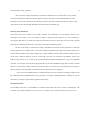
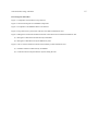
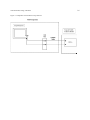
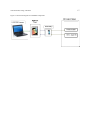
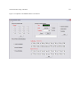
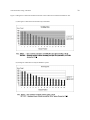
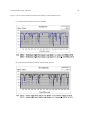
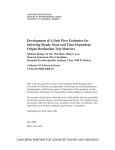
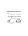
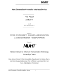
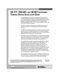
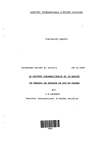
Draft
Development of A Loop Detector Simulator (LOOPSIM) for In-Laboratory Traffic Research and Education
Patikhom Cheevarunothai
Graduate Research Assistant
Department of Civil & Environmental Engineering
University of Washington
Seattle, WA 98195-2700
Tel: (206) 335-2516
Fax: (206) 543-5965
Email: [email protected]
Yinhai Wang
Assistant Professor
Department of Civil & Environmental Engineering
University of Washington
Seattle, WA 98195-2700
Tel: (206) 616-2696
Fax: (206) 543-5965
Email: [email protected]
Nancy L. Nihan
Professor and Director
Transportation Northwest (TransNow)
Department of Civil & Environmental Engineering
University of Washington
Seattle, WA 98195-2700
Tel: (206) 543-9639
Fax: (206) 543-5965
Email: [email protected]
Submission Date: March 20, 2006
Cheevarunothai, Wang, and Nihan
1
Abstract
This paper describes a LOOP detector SIMulator (LOOPSIM) system designed for traffic research and education.
LOOPSIM is capable of simulating calls from loop detectors and testing algorithms executable in the controller. It
can also be used to simulate different patterns of traffic streams and replay collected loop event data. With the aid of
LOOPSIM, researchers and educators can designate traffic characteristics in line with the purpose of the testing or
teaching.
Keywords: LOOPSIM, inductance loop detectors, traffic control system, freeway and intersection applications, inlaboratory testing and teaching.
Cheevarunothai, Wang, and Nihan
2
INTRODUCTION
Inductance loop detectors are the most popular form of detection systems and have been most widely deployed in
the existing road infrastructure [1]. They are a major data source for Advanced Traveler Information Systems (ATIS)
and Advanced Traffic Management Systems (ATMS). Most actuated intersection signal control systems and
freeway monitoring systems use loop detectors for vehicle detection. Loop detectors may be deployed as single
loops to measure traffic volume and lane occupancy or dual loops to collect speed and vehicle length data in
addition to the single-loop measurements. An inductance loop detector contains two parts: a field component and a
Detector Electronics Unit (DEU). The field component consists of one or more turns of insulated loop wire wound
in a shallow slot sawed into the pavement, a pull box at curbside, and a lead-in cable that connects the pull box and
the DEU. The DEU is housed in controller cabinet. Figure 1 shows the components of an inductance loop detector
system.
Each loop detector is a tuned electrical circuit of which the loop wire is the inductive element. When a
vehicle drives over the loop wire, eddy currents are induced around the peripheral metal of the vehicle. Although the
iron mass of the vehicle’s engine, transmission, or differential will increase the loop inductance due to the
ferromagnetic effect, the decrease in inductance from the eddy currents more than offsets the increase from the
ferrous mass, and the net effect of the vehicle’s presence is an overall reduction in loop inductance. Therefore, when
a vehicle is on top of a loop detector, it decreases the inductance of the loop. This decrease in inductance then
triggers the DEU’s output relay or solid state circuit which, in turn, switches the output voltage to the controller to a
low level (close to 0 volts) signifying that a vehicle’s presence has been detected [1]. Typically, a controller scans
loop detector outputs 60 times a second or at 60 Hz [2-3].
To assure the effectiveness of actuated intersection signal control systems and freeway monitoring systems,
hardware and software of the systems should be tested before deployment. However, research laboratories, where
these tests are typically conducted, generally do not have the field component of a loop detector system and,
therefore, may not have live loop inputs for the tests. Although controller cabinets have some built-in test features,
system tests enabled by these features tend to be relatively simple.
Educators always try to prepare the next generation of traffic engineers with a profound understanding of
traffic signal control systems and freeway monitoring systems. The best way to achieve this goal is through handson experience. The problem is so similar to the testing of hardware and software of the traffic systems that the
Cheevarunothai, Wang, and Nihan
3
unavailability of live loop detector outputs obstructs educators from reaching their purpose. Installation of physical
loop detectors in teaching areas may be impossible because of their cost and space requirements.
The Controller Interface Device (CID) developed by the National Institutes of Advanced Transportation
Technology (NIATT) provides a data exchange interface between computers running simulation software and traffic
controllers, so that signal timing plans can be tested with controller hardware in a laboratory before being deployed
in the field [4-7]. The CIDs have enabled Hardware-In-The-Loop Simulations (HITLS) and made traffic simulation
results more reliable. However, CIDs are not designed for simulating loop event data for in-laboratory research and
education. The frequency of providing loop event data from a CID depends on the microscopic simulation software
that drives it. Typically, a microscopic simulation software package has a deterministic frequency of recalculating
the position of each vehicle between 1 and 10 HZ [5]. This limits the time resolution of loop event data to 0.1 to 1
second, which is much lower than the 0.0167 second resolution level for most loop detection systems. Additionally,
using a CID for loop event data simulation requires purchasing both simulation software and a CID. This can easily
cost around $3,000.
Therefore, a loop detector simulator that can generate precise real-time live loop inputs to controllers at an
affordable cost is desirable for in-laboratory traffic research and education. This paper describes an affordable
LOOP detector SIMulator (LOOPSIM) developed by the Smart Transportation Applications and Research
Laboratory (STAR Lab) at the University of Washington (UW). LOOPSIM was designed to enable inductance loop
detector outputs when the field component is absent. LOOPSIM is a computer application with a supporting data
communication device, executable on Windows 2000 and XP operating systems. If properly connected to a
controller cabinet, LOOPSIM and the DEU can form up a virtual inductance loop detector. The only difference
between this virtual loop detector and a real inductance loop is the method of actuating a call. The real inductance
loop’s DEU senses the inductance change from the presence of a vehicle, but the virtual loop places a call through
the computer program of LOOPSIM and its relay circuit. A controller cannot tell if a received call was from a virtual
loop or a real loop. Like a real inductance loop, a virtual loop can be used to provide live inputs to controllers.
Additionally, since loop detector inputs through a virtual loop are controllable, a virtual loop can also be used to
simulate inputs from traffic streams with different characteristics. This is considered a very important feature
because special tests and teaching that require inputs from traffic flows with specific traffic conditions can be
designed and conducted with the aid of LOOPSIM. Such tests may not be feasible with real loop detectors whose
Cheevarunothai, Wang, and Nihan
4
outputs are generally induced by uncontrollable traffic patterns and are not easily verified. Consequently, LOOPSIM
offers an advantage to researchers and educators who can cost-effectively set up a virtual loop detector and
intentionally designate a traffic flow with desired characteristics for controlled laboratory studies in line with the
purpose of their testing or teaching.
SYSTEM DESIGN AND IMPLEMENTATION
System Components and Functions
To simulate the output of an inductance loop to controllers, LOOPSIM should have two output stages: high voltage
(12 volts) and low voltage (0 volts). High voltage represents the “off” status of an inductance loop (i.e., no vehicle is
on the loop) and low voltage represents the loop’s “on” status (i.e., a vehicle is on the loop). Since communication
ports of computers typically handle voltage between 0 volts and 5 volts, an external power supply at 12 volt level is
needed to meet the output requirements.
Considering that the Model 332 cabinet is most widely used in Washington State, the LOOPSIM design
was based on a Model 332 cabinet with a Type 170 controller. The DEUs used were 222-series loop amplifier cards
[8]. When the field component of an inductance loop detector is missing, the DEU stays in the “open loop” status,
which is typically a result of physical loop wire or connection failures. The DEU output voltage is low under the
“open loop” status. However, if a DEU is unplugged from the cabinet, its corresponding output channels in the Input
File will remain at high voltage that indicates no physical loops are connected to the channels. This feature is
standard for all Model 332 cabinets and we use the high voltage of the Input File as the external power supply for
high voltage output of LOOPSIM. In the Model 332 cabinet, the DEU output signals are available for the Type 170
controller to poll at the Input File.
As shown in Figure 2, LOOPSIM is placed between the Input File and the Type 170 controller of the
controller cabinet. Such a connection does not require any further wiring change in the cabinet. When LOOPSIM
simulates a call (or the “on” status), it simply cuts the Input File out of the circuits and sends a low voltage signal to
the controller. If the “off” status is simulated, LOOPSIM cuts itself out of the circuit with mechanical relays to
make the controller directly connect to the Input File whose voltage stays at 12 volts.
Cheevarunothai, Wang, and Nihan
5
Specifically, LOOPSIM is designed to contain the following five components:
•
LOOPSIM Software.
The main function of the LOOPSIM software is to control the digital Input/Output card according to the
users’ objective. It has been developed in C# language.
•
A laptop computer with a Personal Computer Memory Card International Association (PCMCIA) port.
The recommended configurations of the laptop computer include Windows 2000 or Windows XP operating
system, a Pentium 4 processor, and 512 MB of Double Data Rate Synchronous Dynamic Random Access
Memory (DDR SDRAM).
•
Digital Input/Output (I/O) Card
This card is required to connect the laptop computer with the PCMCIA port at one end and drive the
mechanical relay circuits at the other end. The number of I/O channels needed depends on applications.
Each channel must be able to send events at 60 HZ or more. In our implementation, we selected the PCCARD-D24/CTR3 digital I/O card [9]. It has 3 ports with eight channels for each port. All 24 channels are
programmable as input or output channels. The output high is 3.0 v min @ -2.5 mA and output low is 0.4 v
max @ 2.5 mA.
•
Mechanical Relay Circuits
Mechanical relay circuits selected in LOOPSIM must be drivable by the digital I/O card. In our
implementation, the compact Single Pole Single Throw (SPST) reed relay drivable with the PC-CARDD24/CTR3 card was used. The nominal current of the SPST reed relay is 20mA at 5VDC.
•
Cable Connectors
Normal 22-guage cables are used to connect the PC-CARD-D24/CTR3 card, the mechanical relays, Input
File, and the controller input.
LOOPSIM is designed to provide loop inputs to controller cabinets for testing and teaching purposes. It supports
channel connection tests, vehicle arrival pattern simulations, and roadway traffic emulations features. Channel
connection tests are necessary to determine whether the test system has been correctly set up before formal test or
teaching. Some traffic control or operation algorithms must be tested with known arrival patterns. The vehicle
arrival pattern simulations feature provides direct support for such tests. Most frequently, a new algorithm is best
Cheevarunothai, Wang, and Nihan
6
tested with traffic data collected from designated roadways. The roadway traffic emulations feature reads a loop
event data file recorded by the Detector Event DAta Collection (DEDAC) system [3] or the Advanced Loop Event
Data Analyzer (ALEDA) [10] and replays them to emulate the roadway traffic exactly to the controller and the
traffic event data collection system.
System Implementation Issues
LOOPSIM was developed using the Microsoft Visual C#.NET technology [11] and the additional Universal Library
documents from the manufacturer of the digital input/output device [9]. The program is executable on Windows
2000 or XP Windows operating system.
Since a traffic controller typically scans a loop detector’s output at 60 Hz, LOOPSIM should be able to
simulate loop detector event data at 60 Hz or higher. This requires using a high-resolution timer in LOOPSIM
implementation. A timer is a program component that allows programmers to specify a recurring interval at which
the elapsed event is raised in computer applications. A multimedia timer is used in LOOPSIM for more accurate
event timing. Multimedia timer services allow applications to schedule timer events with the greatest resolution (or
accuracy) possible for the hardware platform. It runs on its own thread and moves among threads to handle the
raised elapsed event, resulting in greater accuracy than other timers in raising the event on time. Its resolution on the
hardware platform tested can accurately support simulation at up to 90 Hz.
The multithreading program technique was used to control parallel tasks in LOOPSIM. Of the three ports
with the PC-CARD-D24/CTR3 card, two ports (sixteen channels) were programmed as output channels and can
send signals out simultaneously at a high frequency (60 Hz or higher). This makes LOOPSIM capable of simulating
sixteen inductance loops simultaneously. Since loop detectors work independently, each channel is managed by one
independent thread in LOOPSIM.
Since the typical voltage output from computer ports are between 0 volts and 5 volts, an external power
supply of 12 volts is needed for simulating the “off” status of an inductive loop. We recommend using the Input File
of the Model 332 cabinet as the external power supply for high voltage signals. A mechanical relay is used to switch
between the high voltage from the Input File when simulating the “off” status and the low voltage from the PCCARD-D24/CTR3 card when simulating the “on” status for each channel. The compact SPST reed relay drivable
with the PC-CARD-D24/CTR3 card was selected in our implementation of LOOPSIM to conduct this function.
Cheevarunothai, Wang, and Nihan
7
System Features
The main user interface of LOOPSIM is shown in Figure 3. It contains components that support channel connection
tests, vehicle arrival pattern simulations, and roadway traffic emulation features.
Channel Connection Tests
The main purpose of the channel connection tests is to check the operation of every channel before actual testing and
teaching. It is recommended that users check the status of every channel, using this feature, before using other
LOOPSIM features.
Before conducting the channel connection tests, a user needs to choose which channels to test by selecting
the check boxes of channels listed on the main user interface. Then, pushing the “ON” button will cause each
checked channel to switch to the low voltage status. Remember that low voltage represents the “on” status of the
virtual loop to the controller. After the “ON” button is clicked, it becomes the “OFF” button. Once the “OFF” button
is clicked, the channel connection tests terminate and the channels switch back to high voltage status.
Vehicle Arrival Pattern Simulations
Vehicle arrival patterns are important parameters for many simulation applications. The CORridor SIMulation
(CORSIM) package developed through the Federal Highway Administration (FHWA) uses a uniform distribution as
the default arrival pattern for entry node vehicle generation. CORSIM has also made two other arrival distributions,
normal and Erlang, available to model random arrivals [12]. Many traffic control and assignment algorithms are also
based on certain assumptions of vehicle arrival patterns. To facilitate the test of such algorithms, three vehicle
arrival distributions were implemented: uniform, normal, and Erlang. A user can click to select the desired vehicle
arrival pattern for the test, and LOOPSIM will create a loop event data sequence that follows the designated
distribution for the controller to read.
Cheevarunothai, Wang, and Nihan
8
Here we use the example of uniform arrival pattern to illustrate how to use this feature. A user needs to
specify the hourly traffic volume and average speed (in mph) for each lane on the LOOPSIM interface. These
parameters will be used to calculate the time headways between consecutive vehicles and the scan counts for each
vehicle based on the vehicle length distribution observed by Wang and Nihan [13].
Roadway Traffic Emulations
This feature allows the recreation of true traffic situations for in-laboratory test and teaching. There are two
advantages to this feature: (1) we can control test input to satisfy the specific purpose of a test or teaching by
choosing the right data set recorded at the right time and location; and (2) a chosen data set can be used as ground
truth data for evaluating the performance of systems or estimation models being tested.
Because of the ability to control the test input, LOOPSIM can be used to test the performance of real-time
traffic applications. For example, before a new speed estimation algorithm using single-loop outputs is deployed, it
must be tested, preferably using field-recorded loop event data. With the roadway traffic emulations feature, this test
can be easily conducted. Suppose we have several loop event data sets collected by the DEDAC system from
inductive loop stations on I-5. To test the new speed estimation algorithm implemented in a Type 170 compatible
controller, we can simply select the most appropriate data set and use LOOPSIM to replay this previously recorded
data set to recreate the true traffic situation at the time the data was recorded. Since the ground truth event data are
known, evaluation of the algorithm’s performance becomes much easier and compelling.
Next version of LOOPSIM will have a feedback function from the controller to the laptop computer. With
the feedback function, LOOPSIM will be more powerful. For example, LOOPSIM will have capability to test the
performance of adaptive signal control algorithms in laboratory!
SYSTEM TESTING
The reliability and accuracy of LOOPSIM was evaluated in the STAR Lab at the University of Washington. The
evaluation was conducted through two types of tests: (1) connection tests, and (2) performance & accuracy tests.
Cheevarunothai, Wang, and Nihan
9
Connection Tests
Connection tests are required before LOOPSIM is used to conduct more complicated tests or teaching. As the first
step of the LOOPSIM evaluation, connection tests were preformed to ensure that LOOPSIM could work together
with the available traffic control devices, including the Model 332 cabinet and the Type 170 controller. LOOPSIM
was connected between the Type 170 controller and the Input File of the Model 332 cabinet. This connection
follows exactly the design of LOOPSIM as specified in Figure 2.
The connections for the sixteen output channels of LOOPSIM were tested individually to ensure that they
were properly connected. Then random combinations of the output channels were tested to make sure that channels
did not interfere with each other. These tests were accomplished with the channel connection tests feature of
LOOPSIM. A multi-meter was used to measure the voltage of signals feeding the Type 170 controller. The voltage
corresponding to the simulated “on” status was verified to be very close to 0 volts and the voltage in response to the
simulated “off” status was found to be approximately 12 volts. Additionally, we used the DEDAC system to record
the outputs of each virtual loop detector. All the simulated “on” and “off” statuses were successfully captured by the
DEDAC system.
These test results concluded that the design of LOOPSIM was reasonable and that all sixteen output
channels were successfully connected and worked independently.
Performance & Accuracy Tests
This set of tests was conducted to evaluate the performance and accuracy of LOOPSIM when using the vehicle
arrival pattern simulations and the roadway traffic emulation features. Performance refers to whether loop event data
can be simulated at the desired frequency without significant delays. Accuracy indicates whether a simulated event
data sequence is preserved at the controller input side.
Without changing the connections set up in the connection tests, we conducted two more tests: one for the
vehicle arrival pattern simulations feature (only uniform distribution was tested) and the other for the roadway
traffic emulation feature. The results for both tests can be easily verified by comparing the original data file in
LOOPSIM with the received data file by the DEDAC system. The only difference between these two tests was that
the original data file for testing the feature of vehicle arrival pattern simulations was generated by LOOPSIM based
on a uniform distribution of vehicle arrival times and the observed vehicle length distribution by Wang and Nihan
Cheevarunothai, Wang, and Nihan
10
[13] and the test data for roadway traffic emulation were previously recorded by the DEDAC system at a known
location and time. Since a Type 170 controller typically scans a loop detector at 60 Hz, we configured both
LOOPSIM and the DEDAC system to work at 60 Hz for this test.
The vehicle arrival pattern simulations feature was tested first. We assumed there was a roadway section
with eight lanes and each lane had two single loops deployed (Figure 4). Channels 1 through 8 corresponded to the
first eight loops and channels 9 through 16 corresponded to the second eight loops for lane 1 through lane 4 and lane
5 through lane 8, respectively. The hourly vehicle volume was 500 for lane 1. From lane 1 through lane 8, volume
increases by 100 with each increase of lane number. Average traffic speeds across lanes were assumed to be
constant at 60 mph. The test lasted 15 minutes. The comparisons between the LOOPSIM created data and the
DEDAC system received data are shown in Figure 5(a) and 5(b). The SENDC and RECVC curves represent the
scan counts/car from sending and receiving data files, respectively. Similarly, vehicle time headways from sending
and receiving data files are shown by SENDHW and RECVHW curves, respectively. There was a time delay of 16
milliseconds (ms). The mean absolute error between the two data sets was zero. The sent event data sequence was
preserved exactly in the received data file. These test results indicate that LOOPSIM performed well at the 60 Hz
working frequency and the accuracy was 100%.
Similarly, the roadway traffic emulation feature was tested with the loop event data collected by the
DEDAC system at 13:14:43 to 14:02:22 on May 16, 2002, from station ES-163R on I-5. The simulated signal
sequence by LOOPSIM and the received signal sequence by the DEDAC system are shown in Figure 6(a) and 6(b),
respectively. Please note that the status of one loop detector is recorded in one bit. One byte contains the statuses of
eight loop detectors at a particular moment. All sixteen channels are therefore recorded in two bytes (each byte is
shown as a number range from 0 to 255).
In Figure 6(a), the SEND1 curve represents the status of loops 1 through 8 and the SEND2 curve represents
the status of loops 9 through 16 sent by LOOPSIM. Correspondingly, in figure 6(b), the RECV1 curve shows the
received status of loops 1 through 8 and the RECV2 curve denotes the received status of loops 9 through 16. The
time interval between any two consecutive points is approximately 16.7 ms. Comparison between the corresponding
curves did not find any differences except the consistent system delay of about 16 ms. This test supports the
conclusion from the first test, i.e., LOOPSIM performed superbly at 60 Hz with guaranteed accuracy and sequential
order of the test data set.
Cheevarunothai, Wang, and Nihan
11
CONCLUSIONS AND RECOMMENDATIONS FOR FUTURE IMPROVEMENT
Inductance loops are the most widely deployed traffic sensors in the existing road infrastructure. They are a major
data source for Advanced Traveler Information Systems (ATIS) and Advanced Traffic Management Systems
(ATMS). Most actuated intersection signal control systems and freeway monitoring systems use loop detectors for
vehicle detection, e.g., adaptive signal control systems and ramp metering systems. To assure the effectiveness of
these systems, both hardware and software should be tested before deployment. Additionally, the hands-on
experience on traffic control systems is indispensable for the future generation of traffic engineers. Field testing and
teaching are generally not the first choice because any failure of the traffic system may cost too much. Therefore, inlaboratory testing and teaching is preferred. However, live loop detector inputs may not be available in laboratories
and this deficiency may seriously reduce the diversity of test and teaching methods.
LOOPSIM, as described in this paper, was designed to make live loop data inputs available in laboratories for
traffic research and education. It was developed using Microsoft Visual C#.NET technology and the additional
Universal Library documents from the manufacturer of the digital input/output device. The program is executable on
Windows 2000 or XP Windows operating system. The hardware components of LOOPSIM include a laptop
computer with a PCMCIA port, a digital data I/O card, and mechanical relays. Such a simple configuration is very
affordable for research institutes and universities. In our implementation, less than $400 was spent for the hardware
components connecting the laptop computer and the controller cabinet.
LOOPSIM is capable of generating output events of loop detectors at a high frequency (60 Hz and above).
Test results of LOOPSIM concluded that the system is reliable and accurate. LOOPSIM contains three major
features: channel connection tests, vehicle arrival pattern simulations, and roadway traffic emulations. These
features enable a variety of system tests in laboratories at a low cost and make performance evaluations more
accurate.
We will continue to improve LOOPSIM by adding more simulation features and testing it with different
hardware settings, including other types of controllers and cabinets. We are currently working on the feedback
function from the controller to the laptop computer. Next version LOOPSIM will be more powerful with such a new
function. We believe that there is a great potential to use LOOPSIM for advanced traffic research and education.
Cheevarunothai, Wang, and Nihan
12
ACKNOWLEDGEMENTS
The authors express their deep appreciation to Mr. Bryan Bailey at Washington State Department of Transportation
and Mr. Mike Whiteaker at the City of Bellevue Department of Transportation for providing test devices used in this
study. The authors are also grateful for the financial support to the STAR Lab from TransNow (USDOT University
Transportation Center, Federal Region 10) and Department of Civil and Environmental Engineering at the
University of Washington.
Cheevarunothai, Wang, and Nihan
13
REFERENCES:
[1] ITE (Institute of Transportation Engineers). Traffic Detector Handbook, 2nd Edition, Washington D.C.,
1997.
[2] Coifman, B., D. Lyddy, and A. Sabardonis. “The Berkeley Highway Laboratory- Building on the I-880
Field Experiment.” Proc. IEEE ITS Council Annual Meeting, IEEE, 2000, pp. 5-10.
[3] Zhang, X., Y. Wang, N. L. Nihan, and M. E. Hallenbeck. “Development of A System to Collect Loop
Detector Event (Individual Vehicle) Data.” In Transportation Research Record: Journal of the
Transportation Research Board, No. 1855, TRB, National Research Council, Washington, D.C., 2003, pp.
168-175.
[4] NIATT (National Institute for Advanced Transportation Technology) Tech Brief, A Publication of the
National Institute for Advanced Transportation Technology, University of Idaho, October 2002.
<http://www.webs1.uidaho.edu/niatt/publications/Tech_Brief/Oct02.pdf> Accessed on (July 25, 2004)
[5] NIATT (National Institute for Advanced Transportation Technology). Controller Interface Device (CID) II,
Final Report for Office of University Research and Education, U.S. Department of Transportation, NIATT
(National Institute for Advanced Transportation Technology), University of Idaho, November 2001.
<http://ntl.bts.gov/lib/19000/19100/19165/PB2002104697.pdf>. Accessed on (July 25, 2004).
[6] Bullock, D., B. Johnson, R.B. Wells, M. Kyte, and Z. Li. “Hardware-In-The-Loop Simulation.”
Transportation Research Part C, 12 (2004), pp. 73-89.
[7] Engelbrecht, R.J., K.N. Balke, S.P. Venglar, R.S. Sunkari. “Recent Applications of Hardware-In-The-Loop
Traffic Simulation.” Institute of Trasportation Engineers Meeting and Exhibit 2000, Compendium of
papers, pp.14.
[8] RENO A&E. (2004)Website. <http://www.renoae.com/Documentation/G/Released/222%20(8-27-98).pdf>.
Accessed on (July 25, 2004).
[9] Sealevel Systems, Inc. (2004). Model PC-CARD-D24/CTR3 User Manual. File
<http://measurementcomputing .com/PDFManuals/pc-card-d24_ctr3.pdf>. Accessed on (July 18, 2004).
[10] Cheevarunothai, P., Y. Wang, and N. L. Nihan. Development of Advanced Loop Event Analyzer (ALEDA)
th
for Investigations of Dual-Loop Detector Malfunctions. In The 12 World Congress on Intelligent
Transportation Systems, San Francisco, 2005.
Cheevarunothai, Wang, and Nihan
14
[11] Microsoft Developer Network Library (MSDN). <http://www.msdn.microsoft.com/library/> Accessed on
(July 1, 2004).
[12] Clark, D. C., W. T. Scherer, and B. L. Smith. “Performance-Cost Evaluation Methodology for ITS
Equipment Deployment.” Research report for the Center for ITS Implementation Research. 2000.
<http://www.paragoncom.com/ITS/papers3/corsim.htm#_Toc482685636> Accessed on (July 29, 2004).
[13] Wang, Y., and L.N. Nihan. “Can Single-Loop Detectors Do the Work of Dual-Loop Detectors?”, ASCE
Journal of Transportation Engineering, 129(2), 2003, pp. 169-176.
Cheevarunothai, Wang, and Nihan
Lists of Figures and Tables
Figure 1. Components of an Inductive Loop Detector
Figure 2. Connection Diagram of LOOPSIM Components
Figure 3. A Snapshot of LOOPSIM’s Main User Interface
Figure 4. Loop Detectors Layout for the Vehicle Arrival Pattern Simulations Test
Figure 5. Histograms of Sent Data and Received Data in the Vehicle Arrival Pattern Simulations Test
(a) Histogram of Data Generated and Sent by LOOPSIM
(b) Histogram of Data Received by the DEDAC System
Figure 6. Curves of Sent and Received Data in the Roadway Traffic Emulations Test
(a) Field Recorded Event Data Sent by LOOPSIM
(b) Event Data Received by the DEDAC System during the Test
15
Cheevarunothai, Wang, and Nihan
Figure 1. Components of an Inductive Loop Detector
16
Cheevarunothai, Wang, and Nihan
Figure 2. Connection Diagram of LOOPSIM Components
17
Cheevarunothai, Wang, and Nihan
Figure 3. A Snapshot of LOOPSIM’s Main User Interface
18
Cheevarunothai, Wang, and Nihan
Figure 4. Loop Detectors Layout for the Vehicle Arrival Pattern Simulations Test
19
Cheevarunothai, Wang, and Nihan
Figure 5. Histograms of Sent Data and Received Data in the Vehicle Arrival Pattern Simulations Test
(a) Histogram of Data Generated and Sent by LOOPSIM
(b) Histogram of Data Received by the DEDAC System
20
Cheevarunothai, Wang, and Nihan
Figure 6. Curves of Sent and Received Data in the Roadway Traffic Emulations Test
(a) Field Recorded Event Data Sent by LOOPSIM
(b) Event Data Received by the DEDAC System during the Test
21