1
NI-DSP
™
Software Reference Manual
for LabVIEW® for Windows
Digital Signal Processing Software for the PC
December 1993 Edition
Part Number 320571-01
© Copyright 1993 National Instruments Corporation.
All Rights Reserved.
National Instruments Corporate Headquarters
6504 Bridge Point Parkway
Austin, TX 78730-5039
(512) 794-0100
Technical support fax: (800) 328-2203
(512) 794-5678
Branch Offices:
Australia (03) 879 9422, Austria (0662) 435986, Belgium 02/757.00.20, Canada (Ontario) (519) 622-9310,
Canada (Québec) (514) 694-8521, Denmark 45 76 26 00, Finland (90) 527 2321, France (1) 48 14 24 24,
Germany 089/741 31 30, Italy 02/48301892, Japan (03) 3788-1921, Netherlands 03480-33466, Norway 32-848400,
Spain (91) 640 0085, Sweden 08-730 49 70, Switzerland 056/20 51 51, U.K. 0635 523545
Limited Warranty
The media on which you receive National Instruments software are warranted not to fail to execute programming
instructions, due to defects in materials and workmanship, for a period of 90 days from date of shipment, as
evidenced by receipts or other documentation. National Instruments will, at its option, repair or replace software
media that do not execute programming instructions if National Instruments receives notice of such defects during
the warranty period. National Instruments does not warrant that the operation of the software shall be uninterrupted
or error free.
A Return Material Authorization (RMA) number must be obtained from the factory and clearly marked on the
outside of the package before any equipment will be accepted for warranty work. National Instruments will pay the
shipping costs of returning to the owner parts which are covered by warranty.
National Instruments believes that the information in this manual is accurate. The document has been carefully
reviewed for technical accuracy. In the event that technical or typographical errors exist, National Instruments
reserves the right to make changes to subsequent editions of this document without prior notice to holders of this
edition. The reader should consult National Instruments if errors are suspected. In no event shall National
Instruments be liable for any damages arising out of or related to this document or the information contained in it.
EXCEPT AS SPECIFIED HEREIN, NATIONAL I NSTRUMENTS MAKES NO WARRANTIES, EXPRESS OR IMPLIED,
AND SPECIFICALLY DISCLAIMS ANY WARRANTY OF MERCHANTABILITY OR FITNESS FOR A PARTICULAR
PURPOSE. C USTOMER'S RIGHT TO RECOVER DAMAGES CAUSED BY FAULT OR NEGLIGENCE ON THE PART
OF NATIONAL INSTRUMENTS SHALL BE LIMITED TO THE AMOUNT THERETOFORE PAID BY THE CUSTOMER.
NATIONAL I NSTRUMENTS WILL NOT BE LIABLE FOR DAMAGES RESULTING FROM LOSS OF DATA, PROFITS,
USE OF PRODUCTS, OR INCIDENTAL OR CONSEQUENTIAL DAMAGES, EVEN IF ADVISED OF THE POSSIBILITY
THEREOF. This limitation of the liability of National Instruments will apply regardless of the form of action,
whether in contract or tort, including negligence. Any action against National Instruments must be brought within
one year after the cause of action accrues. National Instruments shall not be liable for any delay in performance due
to causes beyond its reasonable control. The warranty provided herein does not cover damages, defects,
malfunctions, or service failures caused by owner's failure to follow the National Instruments installation, operation,
or maintenance instructions; owner's modification of the product; owner's abuse, misuse, or negligent acts; and
power failure or surges, fire, flood, accident, actions of third parties, or other events outside reasonable control.
Copyright
Under the copyright laws, this publication may not be reproduced or transmitted in any form, electronic or
mechanical, including photocopying, recording, storing in an information retrieval system, or translating, in whole or
in part, without the prior written consent of National Instruments Corporation.
Trademarks
LabVIEW ®, NI-DAQ ®, RTSI ®, and NI-DSP™ are trademarks of National Instruments Corporation.
Product and company names listed are trademarks or trade names of their respective companies.
Warning Regarding Medical and Clinical Use
of National Instruments Products
National Instruments products are not designed with components and testing intended to ensure a level of reliability
suitable for use in treatment and diagnosis of humans. Applications of National Instruments products involving
medical or clinical treatment can create a potential for accidental injury caused by product failure, or by errors on the
part of the user or application designer. Any use or application of National Instruments products for or involving
medical or clinical treatment must be performed by properly trained and qualified medical personnel, and all
traditional medical safeguards, equipment, and procedures that are appropriate in the particular situation to prevent
serious injury or death should always continue to be used when National Instruments products are being used.
National Instruments products are NOT intended to be a substitute for any form of established process, procedure, or
equipment used to monitor or safeguard human health and safety in medical or clinical treatment.
Contents
About This Manual .................................................................................................................... xi
Assumption of Previous Knowledge ........................................................................................................ xi
Organization of This Manual .................................................................................................................... xi
Conventions Used in This Manual............................................................................................................ xii
Related Documentation ............................................................................................................................ xiv
Additional Software .................................................................................................................................. xiv
NI-DAQ for DOS/Windows/LabWindows ................................................................................ xiv
Developer Toolkit ...................................................................................................................... xv
Compatible Hardware ............................................................................................................................... xv
Customer Communication ........................................................................................................................ xv
Part 1
Getting Started with NI-DSP ........................................................................................ 1-1
Product Overview ..................................................................................................................................... 1-1
The NI-DSP Software ............................................................................................................................... 1-1
What Your Distribution Diskettes Should Contain .................................................................... 1-2
Installing NI-DSP for LabVIEW for Windows ........................................................................................ 1-2
Board Configuration ................................................................................................................................. 1-3
Installation on an ISA (or AT) Bus Computer ........................................................................... 1-3
Installation on an EISA Bus Computer ...................................................................................... 1-3
Part 2
Introduction to the NI-DSP Analysis VIs .................................................... 1-1
Using the NI-DSP VIs in LabVIEW ........................................................................................................ 1-1
AT-DSP2200 Software Overview ............................................................................................................ 1-1
Memory Management and Data Transfer ................................................................................................. 1-2
Special Features of the NI-DSP Analysis VIs .......................................................................................... 1-5
Hints for Improving the Execution Speed on the DSP Board .................................................... 1-7
An Example of Using NI-DSP Analysis VIs ............................................................................................ 1-8
Part 3
NI-DSP Function Reference
Chapter 1
NI-DSP Analysis VI Reference Overview ............................................................................... 1-1
The NI-DSP Analysis VI Overview ......................................................................................................... 1-1
Analysis VI Organization ......................................................................................................................... 1-3
Accessing the NI-DSP Analysis VIs ........................................................................................................ 1-3
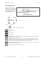
About the Fast Fourier Transform (FFT) .................................................................................................. 1-4
About Filtering .......................................................................................................................................... 1-5
About Windowing .................................................................................................................................... 1-6
Chapter 2
NI-DSP Analysis VI Reference ........................................................................................................ 2-1
Copy Mem(DSP to DSP) .......................................................................................................................... 2-1
Copy Mem(DSP to LV) ............................................................................................................................ 2-2
Copy Mem(LV to DSP) ............................................................................................................................ 2-3
© National Instruments Corporation
v
NI-DSP SRM for LabVIEW for Windows
Contents
DSP Absolute ............................................................................................................................................ 2-4
DSP Add ................................................................................................................................................... 2-5
DSP Allocate Memory .............................................................................................................................. 2-6
DSP Blackman Window ........................................................................................................................... 2-7
DSP Blackman Harris Window ................................................................................................................ 2-8
DSP Butterworth Coefficients .................................................................................................................. 2-9
DSP Chebyshev Coefficients .................................................................................................................... 2-10
DSP Clip ................................................................................................................................................... 2-11
DSP Complex FFT.................................................................................................................................... 2-12
DSP Convolution ...................................................................................................................................... 2-13
DSP Correlation ........................................................................................................................................ 2-14
DSP Cross Power ...................................................................................................................................... 2-15
DSP Custom .............................................................................................................................................. 2-16
DSP Decimate........................................................................................................................................... 2-17
DSP Deconvolution .................................................................................................................................. 2-18
DSP Derivative ......................................................................................................................................... 2-19
DSP Divide ............................................................................................................................................... 2-20
DSP Elliptic Coefficients .......................................................................................................................... 2-21
DSP Equi-Ripple Bandpass ...................................................................................................................... 2-23
DSP Equi-Ripple Bandstop ...................................................................................................................... 2-25
DSP Equi-Ripple HighPass ...................................................................................................................... 2-27
DSP Equi-Ripple LowPass ....................................................................................................................... 2-29
DSP Exact Blackman Window ................................................................................................................. 2-30
DSP Exponential Window ........................................................................................................................ 2-31
DSP FHT .................................................................................................................................................. 2-32
DSP Flat Top Window .............................................................................................................................. 2-33
DSP Force Window .................................................................................................................................. 2-34
DSP Free Memory .................................................................................................................................... 2-34
DSP Gaussian White Noise ...................................................................................................................... 2-35
DSP General Cosine Window .................................................................................................................. 2-36
DSP Hamming Window ........................................................................................................................... 2-37
DSP Handle to Address ............................................................................................................................ 2-38
DSP Hanning Window.............................................................................................................................. 2-39
DSP IIR Filter ........................................................................................................................................... 2-40
DSP Impulse Pattern ................................................................................................................................. 2-42
DSP Impulse Train Pattern ....................................................................................................................... 2-43
DSP Index Memory .................................................................................................................................. 2-44
DSP Init Memory ...................................................................................................................................... 2-45
DSP Integral .............................................................................................................................................. 2-46
DSP Inv Chebyshev Coeff ........................................................................................................................ 2-47
DSP Inverse FFT ...................................................................................................................................... 2-48
DSP Inverse FHT ...................................................................................................................................... 2-49
DSP Kaiser-Bessel Window ..................................................................................................................... 2-50
DSP Linear Evaluation ............................................................................................................................. 2-51
DSP Load .................................................................................................................................................. 2-51
DSP Log .................................................................................................................................................... 2-52
DSP Max & Min ....................................................................................................................................... 2-53
DSP Median Filter .................................................................................................................................... 2-54
DSP Multiply ............................................................................................................................................ 2-55
DSP Parks-McClellan ............................................................................................................................... 2-56
DSP Polar to Rectangular ......................................................................................................................... 2-59
DSP Polynomial Evaluation ..................................................................................................................... 2-60
DSP Power Spectrum................................................................................................................................ 2-61
DSP Product .............................................................................................................................................. 2-61
DSP Pulse Pattern ..................................................................................................................................... 2-62
DSP Ramp Pattern .................................................................................................................................... 2-63
DSP Random Pattern ................................................................................................................................ 2-64
DSP Rectangular to Polar ......................................................................................................................... 2-65
NI-DSP SRM for LabVIEW for Windows
vi
© National Instruments Corporation
Contents
DSP ReFFT............................................................................................................................................... 2-66
DSP Reset ................................................................................................................................................. 2-66
DSP Reverse ............................................................................................................................................. 2-67
DSP Sawtooth Pattern............................................................................................................................... 2-68
DSP Set ..................................................................................................................................................... 2-69
DSP Shift .................................................................................................................................................. 2-69
DSP Sinc Pattern....................................................................................................................................... 2-70
DSP Sine Pattern....................................................................................................................................... 2-71
DSP Square Pattern................................................................................................................................... 2-72
DSP Square Root ...................................................................................................................................... 2-73
DSP Sort ................................................................................................................................................... 2-74
DSP Start .................................................................................................................................................. 2-75
DSP Subset ............................................................................................................................................... 2-75
DSP Subtract............................................................................................................................................. 2-76
DSP Sum................................................................................................................................................... 2-76
DSP TimeOut ............................................................................................................................................ 2-77
DSP Triangle Pattern ................................................................................................................................ 2-78
DSP Triangular Train................................................................................................................................ 2-80
DSP Triangular Window .......................................................................................................................... 2-81
DSP Uniform White Noise ....................................................................................................................... 2-82
DSP Unwrap Phase ................................................................................................................................... 2-83
DSP Zero Padder ...................................................................................................................................... 2-84
Part 4
NI-DSP Interface Utilities
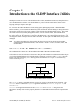
Chapter 1
Introduction to the NI-DSP Interface Utilities .................................................................... 1-1
Overview of the NI-DSP Interface Utilities.............................................................................................. 1-1
Installing the NI-DSP Interface Utilities .................................................................................................. 1-2
Using the NI-DSP Interface Utilities ........................................................................................................ 1-2
Chapter 2
Getting Started with the NI-DSP Interface Utilities ....................................................... 2-1
Creating Your Custom NI-DSP Library ................................................................................................... 2-1
1. Create Your Source Code of C Functions ............................................................................. 2-1
GMaxMin.c Example .................................................................................................. 2-1
Guidelines for the Custom Functions .......................................................................... 2-2
DSP Board Memory Management ............................................................................... 2-3
2. Compile and/or Assemble Source Code ................................................................................ 2-4
3. Add Your Object Filenames to a Linker File (ifile) .............................................................. 2-4
4. Add Your New Function Names to a Library Function List File.......................................... 2-4
Customizing the DSP Library by Deleting Functions ................................................. 2-5
5. Run the Build Dispatch Application to Generate an Assembly Dispatch File ...................... 2-6
6. Compile, Assemble, and Link Your Custom Library............................................................ 2-7
Creating Your LabVIEW Interface .......................................................................................................... 2-8
1. Bundle All of the Input Parameters to Arrays ....................................................................... 2-8
2. Call the Custom VI ................................................................................................................ 2-10
3. Index the Output Arrays to Obtain the Results ..................................................................... 2-10
Executing the Custom Function from LabVIEW ..................................................................................... 2-12
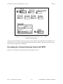
Chapter 3
DSP Board Function Overview ...................................................................................................... 3-1
Data Acquisition Functions ...................................................................................................................... 3-3
© National Instruments Corporation
vii
NI-DSP SRM for LabVIEW for Windows
Contents
Chapter 4
Using the DMA VIs .................................................................................................................................. 4-1
DSP DMA Copy(DSP to LV)................................................................................................................... 4-3
DSP DMA Copy(LV to DSP)................................................................................................................... 4-4
Appendix A
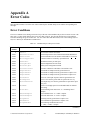
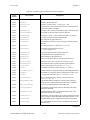
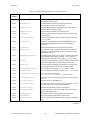
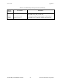
Error Codes .......................................................................................................................................... A-1
Error Conditions........................................................................................................................................ A-1
Appendix B
Customer Communication ............................................................................................... B-1
Glossary ........................................................................................................................................... Glossary-1
Index .......................................................................................................................................................... Index-1
NI-DSP SRM for LabVIEW for Windows
viii
© National Instruments Corporation
Contents
Figures
Part 1
Figure 1-1.
Development Paths with the NI-DSP Software ............................................................................. 1-1
Part 2
Figure 1-1.
Figure 1-2.
Figure 1-3.
Figure 1-4.
Figure 1-5.
Figure 1-6.
Figure 1-7.
Figure 1-8.
Figure 1-9.
Figure 1-10.
Figure 1-11.
Communication between the PC and the DSP Board .................................................................... 1-1
DSP Handle Cluster ....................................................................................................................... 1-3
The Hexadecimal Encoding of a Typical DSP Handle .................................................................. 1-3
Front Panel–An Example of How to Allocate a DSP Handle Cluster ........................................... 1-4
Block Diagram–An Example of How to Allocate a DSP Handle Cluster ..................................... 1-4
DSP Add VI ................................................................................................................................... 1-5
The error in/error out Cluster...................................................................................................... 1-5
An Example That Does Not Use error in/error out for Sequencing VIs .................................... 1-6
An Example of Using the error in/error out Cluster for Sequential VI Execution ..................... 1-7
Front Panel–An Example of Using NI-DSP Analysis VIs ............................................................ 1-8
Block Diagram–An Example of Using NI-DSP Analysis VIs ...................................................... 1-8
Part 3
Figure 1-1.
Figure 1-2.
Choosing DSP2200 from the Functions Menu .............................................................................. 1-4
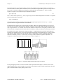
Spectral Leakage Demonstrated Using Convolution ..................................................................... 1-7
Part 4
Figure 1-1.
Figure 1-2.
NI-DSP for DOS Directory Structure ............................................................................................ 1-1
Interface Layers to Onboard Functions .......................................................................................... 1-2
Figure 2-1.
Figure 2-2.
Figure 2-3.
Figure 2-4.
Figure 2-5.
Figure 2-6.
Figure 2-7.
Figure 2-8.
Figure 2-9.
Figure 2-10.
Linker File NIDSPLNK ................................................................................................................. 2-4
Library Function List File NIDSP.fnc ........................................................................................... 2-4
Typical Section of NIDSP.fnc ....................................................................................................... 2-5
Signals Group Section in dspfncs.h ............................................................................................... 2-6
Signals Group Section in dispatch.s............................................................................................... 2-6
How to Bundle Parameters in LabVIEW to Call gmaxmin.c ........................................................ 2-9
How to Connect to Custom VI to Call gmaxmin.c ........................................................................ 2-10
Block Diagram–How to Index the Output Arrays of the Custom VI ............................................ 2-11
Block Diagram–Using the Custom VI to Call gmaxmin.c on theDSP Board from LabVIEW ..... 2-11
Front Panel–Using the Custom VI to Call gmaxmin.c on theDSP Board from LabVIEW ........... 2-12
© National Instruments Corporation
ix
NI-DSP SRM for LabVIEW for Windows
Contents
Tables
Part 1
Table 1-1.
Subdirectories Created by SETUP ................................................................................................. 1-2
Part 3
Table 1-1.
The NI-DSP Analysis VI Groups .................................................................................................. 1-1
Part 4
Table 2-1.
Files Required to Build the Custom DSP Library Example .......................................................... 2-7
Appendix A
Table A-1.
NI-DSP Analysis Library Error Codes .......................................................................................... A-1
NI-DSP SRM for LabVIEW for Windows
x
© National Instruments Corporation
About This Manual
The NI-DSP Software Reference Manual for LabVIEW for Windows explains how to use the NI-DSP software
package for the LabVIEW for Windows environment. The NI-DSP software package contains the NI-DSP Analysis
VIs, which are high-level digital signal processing (DSP) VIs that call the functions that execute on the
AT-DSP2200 plug-in board for IBM AT bus and compatible computers. This manual describes how to use the
NI-DSP Analysis VIs to develop applications in LabVIEW using the AT-DSP2200 board.
The NI-DSP software package also contains the NI-DSP Interface Utilities. The NI-DSP Interface Utilities are a set
of tools and examples that help you customize your NI-DSP Analysis VIs and the DSP Library, which is resident on
the board. This manual contains step-by-step instructions and useful examples to help the LabVIEW developer add
custom algorithms to the NI-DSP Analysis VIs using the NI-DSP Interface Utilities.
Assumption of Previous Knowledge
The material in this manual is for users who are familiar with LabVIEW and the IBM family of computers and
compatible computers.
Organization of This Manual
This manual is divided into four parts.
•
Part 1, Getting Started with NI-DSP, contains a brief product overview, information about the NI-DSP for
LabVIEW for Windows package, and the procedure for installing the software.
•
Part 2, Introduction to the NI-DSP Analysis VIs, describes how to use the NI-DSP Analysis VIs in your
LabVIEW applications. This part also describes how to manage memory on the DSP board from your
LabVIEW application, and how to transfer data between your LabVIEW application and the NI-DSP functions
on the board. This part contains general guidelines for developing NI-DSP applications within LabVIEW.
•
Part 3, NI-DSP Function Reference, is intended as a reference for users familiar with Part 2. Part 3 is organized
as follows:
•
-
Chapter 1, NI-DSP Analysis VI Reference Overview, contains an overview of the NI-DSP Analysis VIs and
includes a list of the VIs. This chapter describes how the NI-DSP Analysis VIs are organized, and how to
access them.
-
Chapter 2, NI-DSP Analysis VI Reference, contains a brief explanation of each NI-DSP Analysis VI. The
VIs are arranged alphabetically.
Part 4, NI-DSP Interface Utilities, explains how to customize the NI-DSP Analysis Library on the board and to
create and run interfaces in LabVIEW to your custom library functions. Part 4 is organized as follows:
-
Chapter 1, Introduction to the NI-DSP Interface Utilities, contains an overview of the NI-DSP Interface
Utilities, installation instructions, and explains how to use the NI-DSP Interface Utilities.
-
Chapter 2, Getting Started with the NI-DSP Interface Utilities, contains a step-by-step example for building
a custom DSP Library, creating a LabVIEW interface to a custom function, and executing the custom
function from the LabVIEW environment. The chapter demonstrates this concept with an example of how
to add a custom function.
© National Instruments Corporation
xi
NI-DSP SRM for LabVIEW for Windows
About This Manual
-
Chapter 3, DSP Board Function Overview, contains an overview of the prototypes of the C-callable
NI-DSP Analysis functions on the DSP board that you can use in your custom programs.
-
Chapter 4, Using the DMA VIs, describes two special VIs that transfer data between the host computer and
the DSP board without interfering with the DSP board.
•
Appendix A, Error Codes, contains a list of the error codes returned by the NI-DSP Analysis VIs and the
corresponding error messages.
•
Appendix B, Customer Communication, contains forms you can use to request help from National Instruments
or to comment on our products and manuals.
•
The Glossary contains an alphabetical list and description of terms used in this manual, including abbreviations,
acronyms, metric prefixes, mnemonics, and symbols.
•
The Index alphabetically lists topics covered in this manual, including the page where the topic can be found.
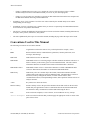
Conventions Used in This Manual
The following conventions are used in this manual:
<>
Angle brackets enclose the name of a key on the keyboard–for example, <enter>.
bold
Bold text denotes menus, command names, parameters, function panel items, error
messages, and warnings.
DSP board
DSP board refers to the AT-DSP2200.
DSP Handle
DSP Handle refers to a 32-bit long integer code that constitutes an indirect reference to a
buffer of memory in the memory space of an AT-DSP2200 board. The code contains
information about the slot number of the board on which that buffer is allocated.
DSP Handle Cluster
DSP Handle Cluster refers to a cluster that constitutes two fields–a DSP Handle and a
32-bit size that indicates the number of elements the DSP Handle holds.
DSP Library
DSP Library refers to a common object file format (COFF) that constitutes NI-DSP
software that resides and runs on the AT-DSP2200 board. The DSP Library consists of
the Kernel, memory management routines, execution control routines, data
communication routines, interrupt handling routines, data acquisition routines and a set of
analysis functions.
<enter>
Key names are in lowercase letters.
Interface Library
Interface Library refers to the part of the NI-DSP software that resides on the PC and is
linked with your application in order to communicate data to and from the DSP board.
The Interface Library communicates with the DSP board using the driver.
italic
Italic text denotes emphasis, a cross reference, or an introduction to a key concept.
italic monospace
Italic text in this font denotes that you must supply the appropriate words or values in the
place of these items.
NI-DSP SRM for LabVIEW for Windows
xii
© National Instruments Corporation
About This Manual
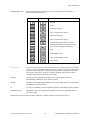
LabVIEW Data Types
Each VI description includes a data type picture for each control and indicator, as
illustrated in the following table:
Control
Indicator
Data Type
Boolean
String
Signed 16-bit integer
Array of signed 16-bit integers
Signed 32-bit integer
Array of signed 32-bit integers
32-bit floating-point number; by default,
floating-point numbers are double precision
Array of 32-bit floating-point numbers
Path
DSP Handle Cluster
Array of DSP Handle Clusters
Error Cluster
monospace
Text in this font denotes text or characters that are to be literally input from the keyboard,
sections of code, programming examples, and syntax examples. This font is also used for
the proper names of disk drives, paths, directories, programs, subprograms, subroutines,
device names, array names, structures, variables, filenames, and extensions, and for
statements and comments taken from program code.
NI-DAQ
NI-DAQ is used throughout this manual to refer to the NI-DAQ software for
DOS/Windows/LabWindows unless otherwise noted.
NI-DSP
NI-DSP is used throughout this manual to refer to the NI-DSP software for LabVIEW for
Windows unless otherwise noted.
PC
PC refers to the IBM PC AT and compatible computers, and to EISA personal computers.
WE DSP32C tools
WE DSP32C tools is used throughout this manual to refer to the AT&T WE DSP32C
Developer Toolkit.
Abbreviations, acronyms, metric prefixes, mnemonics, symbols, and terms are listed in the Glossary.
© National Instruments Corporation
xiii
NI-DSP SRM for LabVIEW for Windows
About This Manual
Related Documentation
The following documentation available from National Instruments contains information that you may find helpful as
you read this manual.
•
AT-DSP2200 User Manual, part number 320435-01
•
LabVIEW Data Acquisition VI Reference Manual, part number 320536-01
•
LabVIEW Getting Started Manual for Windows, part number 320533-01
•
LabVIEW User Manual, part number 320534-01
•
LabVIEW Utility VI Reference Manual, part number 320543-01
•
NI-DAQ Function Reference Manual for DOS/Windows/LabWindows, part number 320499-01
•
NI-DAQ Software Reference Manual for DOS/Windows/LabWindows, part number 320498-01
•
NI-DSP Software Reference Manual for DOS/LabWindows, part number 320436-01
The following documentation also contains information that you may find helpful as you read this manual:
•
"A Computer Program for Designing Optimum FIR Linear Phase Digital Filters," McClellan, Parks, and
Rabiner, IEEE Transactions on Audio and Electroacoustics, Vol. AU-21, No. 6, pp. 506-525, December 1973
•
Digital Filter Design, Parks and Burrus, Wiley-Interscience
•
Discrete-Time Signal Processing, Oppenheim and Schafer, Prentice Hall
•
Numerical Recipes, Cambridge University Press
Additional Software
Additional DSP board software includes NI-DAQ for DOS/Windows/LabWindows and the Developer Toolkit.
NI-DAQ for DOS/Windows/LabWindows
Your AT-DSP2200 is shipped with the NI-DAQ for DOS/Windows/LabWindows software. NI-DAQ has a library
of functions that can be called from your application programming environment. These functions include routines
for analog input (A/D conversion), buffered data acquisition (high-speed A/D conversion), analog output (D/A
conversion), waveform generation, digital I/O, counter/timer, SCXI, RTSI, and self-calibration. NI-DAQ maintains
a consistent software interface among its different versions so you can switch between platforms with minimal
modifications to your code. NI-DAQ comes with language interfaces for Professional BASIC, Turbo Pascal,
Turbo C, Turbo C++, Borland C++, Microsoft C for DOS; and Visual Basic, Pascal, Microsoft C with SDK, and
Borland C++ for Windows. NI-DAQ for DOS/Windows/LabWindows software is on high-density 5.25 in. and
3.5 in. diskettes. You can use the DSP board in conjunction with the National Instruments AT Series data
acquisition boards and software to create a complete solution for integrated data acquisition and data analysis
applications.
NI-DSP SRM for LabVIEW for Windows
xiv
© National Instruments Corporation
About This Manual
Developer Toolkit
The Developer Toolkit, an optional software package that you can purchase separately from National Instruments, is
required for building custom libraries with the NI-DSP Interface Utilities. The Developer Toolkit contains an
AT&T C compiler, assembler, linker, and documentation. With these tools, you can program AT Series DSP boards
directly, using theboard flexibility to custom tailor the DSP Library. The C compiler optimizes WE DSP32C code
and generates assembly language code that can be assembled and linked into a run-time module. When a run-time
module is completed, use the download tools and the debugger to load, debug, and execute the code, set parameters,
and report results. The Developer Toolkit also includes the WE DSP32C Support Software Library User Manual
and the WE DSP32 and WE DSP32C Language Compiler Library Reference Manual.
Compatible Hardware
You can use DSP boards in conjunction with the National Instruments AT Series data acquisition boards. In
particular, the National Instruments AT-DSP2200 is a high-performance, DSP board with high-accuracy audio
frequency (DC to 51.2 kHz) analog input/output for the PC. The AT-DSP2200 gives the PC a dedicated
high-speed numerical computation engine that can perform scientific calculations faster than the general-purpose
80x86 microprocessor on the PC.
Customer Communication
National Instruments wants to receive your comments on our products and manuals. We are interested in the
applications you develop with our products, and we want to help if you have problems with them. To make it easy
for you to contact us, this manual contains comment and configuration forms for you to complete. These forms are
in Appendix B, Customer Communication, at the end of this manual.
© National Instruments Corporation
xv
NI-DSP SRM for LabVIEW for Windows
Part 1
Getting Started with NI-DSP
This part contains a brief product overview, information about the NI-DSP for LabVIEW for Windows package, and
the procedure for installing the software.
Product Overview
The NI-DSP software package comes with a set of LabVIEW VIs that invoke the digital signal processing (DSP)
board-resident high-performance functions that efficiently process large blocks of numerical data and perform
numerically intensive computations. The NI-DSP Analysis VIs include numerical analysis, signal generation, DSP,
windowing, digital filtering, and memory management that are suitable for simulation, modeling, and sophisticated
data processing.
You can use NI-DSP to develop programs in the LabVIEW for Windows environment. This software comes with
the NI-DSP Interface Utilities so you can customize the DSP Library by adding functions to or deleting functions
from the Analysis Library on the DSP board and/or add interfaces to these custom functions in LabVIEW.
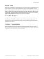
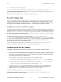
Figure 1-1 shows the development path for NI-DSP in the LabVIEW environment.
The LabVIEW
for Windows
Development
Environment
NI-DSP for
LabVIEW
for Windows
Interface
Utilities
User
Application
AT&T
Development
Environment
and Tools
(Optional)
Figure 1-1. Development Paths with the NI-DSP Software
The NI-DSP Software
The NI-DSP software consists of the NI-DSP for LabVIEW for Windows diskettes.
The NI-DSP software contains a Warranty Registration Form. Please fill out this form and return it to National
Instruments. The Warranty Registration Form entitles you to receive product upgrades and technical support.
NI-DSP SRM for LabVIEW for Windows
1-1
Part 1: Getting Started with NI-DSP
Getting Started with NI-DSP
Part 1
What Your Distribution Diskettes Should Contain
The NI-DSP software package contains the NI-DSP for LabVIEW for Windows Disks (for licensed LabVIEW for
Windows users). If your kit is missing any of these components, contact National Instruments.
Installing NI-DSP for LabVIEW for Windows
Note:
NI-DSP for LabVIEW for Windows is intended for use with the standard LabVIEW for Windows software.
You must install LabVIEW for Windows before installing NI-DSP. You must install the Data Acquisition
Library of LabVIEW to run the NI-DSP software.
Before beginning the software installation, make backup copies of the NI-DSP for LabVIEW for Windows
distribution disks. Copy each disk onto a correctly labeled backup disk and store the original distribution disks in a
safe place.
You can install NI-DSP for LabVIEW for Windows from the DOS prompt, the Windows File Manager, or with the
Run... command from the File menu of the Program Manager.
1.
2.
Insert Disk 1 into the disk drive and run the SETUP.EXE program on Disk 1 using one of the following three
methods.
•
From the DOS prompt, type X: \SETUP (where X is the proper drive designation).
•
From Windows, select Run... from the File menu of the Program Manager. A dialog box appears. Type
X: \SETUP (where X is the proper drive designation).
•
From Windows, launch the File Manager. Click on the drive icon that contains Disk 1. Find SETUP.EXE
in the list of files on that disk and double-click on it.
The installer gives you the option of performing a full installation or a custom installation. Unless you do not
have sufficient disk space (approximately 4 megabytes), National Instruments recommends that you perform a
full installation. After you choose an installation, follow the instructions that appear on the screen.
After calling SETUP, the appropriate directories are created and the needed files are copied to your hard drive.
SETUP can also install the NI-DSP Interface Utilities, discussed in Part 4, NI-DSP Interface Utilities, of this manual.
If you choose Full Installation, SETUP does the following things:
1.
SETUP creates a subdirectory called DSP2200 of the vi.lib subdirectory of the LabVIEW directory.
SETUP decompresses the NI-DSP Analysis VIs (as LabVIEW .LLB files) in the DSP2200 directory.
2.
SETUP copies DSP.DLL to your windows directory.
3.
SETUP creates the subdirectories shown in Table 1-1 under the directory you specified during setup. These
subdirectories make up the NI-DSP Interface Utilities.
4.
SETUP creates a subdirectory called DSP2200 of the EXAMPLES subdirectory of the LabVIEW directory.
SETUP copies all of the NI-DSP VI examples there.
Table 1-1. Subdirectories Created by SETUP
Subdirectory Name
C:\NIDSP\LIB
C:\NIDSP\DISPATCH
C:\NIDSP\EXAMPLES
Part 1: Getting Started with NI-DSP
Description
Library files for linking with stand-alone programs
The Dispatch utility and related files
Contains source code for the examples
1-2
NI-DSP SRM for LabVIEW for Windows
Part 1
Getting Started with NI-DSP
NIDSP is the name you specify during setup.
The SETUP program prompts you for information including the drive letter and directory in which you have
installed the standard LabVIEW package. The program also verifies that your hard disk has enough space to hold
the NI-DSP for LabVIEW for Windows files.
If you choose Custom Installation, SETUP installs only the files you specify.
Board Configuration
There are several board configuration parameters that must be established before an NI-DSP application can execute
properly. These parameters are the board ID number, the board subtype, the base address, the interrupt level, the
DMA channel, and the pathname of the DSP Library files. These parameters are established differently depending
on whether you are installing the AT-DSP2200 in an ISA (or AT) bus computer or an EISA bus computer.
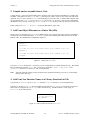
Installation on an ISA (or AT) Bus Computer
A configuration utility is supplied with the LabVIEW data acquisition software for establishing all the configuration
parameters on ISA bus computers. This utility, called WDAQCONF.EXE, saves the configuration parameters in a file
named WDAQCONF.CFG. Use the WDAQCONF utility to assign a board ID number to your AT-DSP2200, to choose
the memory subtype (either 64 Kwords or ≥128 Kwords), to set the base address, interrupt level, and DMA channel,
and to specify the pathname of the DSP Library file.
Two DSP Library files are supplied with your NI-DSP software–LV2200S.OUT and LV2200.OUT.
LV2200S.OUT is intended for use with the 64 Kword version of the AT-DSP2200. LV2200.OUT is intended for
use with any other version of the board. With the WDAQCONF utility, you can enter a complete path that will include
the DSP Library file name. If you enter complete pathnames, you can configure the NI-DSP software to
automatically load custom versions of the DSP Library files.
If you installed the Data Acquisition Library of LabVIEW, you can find WDAQCONF.EXE of your LabVIEW
directory. From Windows, you run WDAQCONF.EXE by double-clicking on its icon.
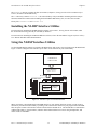
Installation on an EISA Bus Computer
Installing the AT-DSP2200 board on an EISA bus computer involves two different configuration utilities.
•
A system configuration utility is supplied with your computer by your computer vendor. This utility, along with
the !NIC1100.CFG EISA configuration file installed by the LabVIEW SETUP program, is used to assign a
slot number to the AT-DSP2200, to choose the memory subtype (either 64 Kwords or ≥128 Kwords), and to set
the base address, interrupt level, and DMA channel.
There are typically two methods for running your EISA system configuration utility.
•
1.
Boot from the diskette containing the utility and place a copy of the !NIC1100.CFG file on this diskette.
2.
Run the utility from a directory on your hard disk and place a copy of the !NIC1100.CFG file in this
directory. The EISA system configuration utility is typically named CF.EXE.
You must use the WDAQCONF utility to enter the DSP Library file pathname. You can only do this after
completing the EISA system configuration. Refer to the information concerning the establishment of this
pathname in the previous section titled, Installation on an ISA (or AT) Bus Computer.
Before using NI-DSP, you must run WDAQCONF.EXE to configure your DSP board.
For more information about board configuration, refer to Chapter 1, Introduction and Configuration, of the
LabVIEW Data Acquisition VI Reference Manual.
NI-DSP SRM for LabVIEW for Windows
1-3
Part 1: Getting Started with NI-DSP
Part 2
Introduction to the NI-DSP Analysis VIs
This part describes how to use the NI-DSP Analysis VIs in your LabVIEW applications. This part also describes
how to manage memory on the DSP board from your LabVIEW application, and how to transfer data between your
LabVIEW application and the NI-DSP functions on the board. This part contains general guidelines for developing
NI-DSP applications within LabVIEW.
Using the NI-DSP VIs in LabVIEW
LabVIEW users use the NI-DSP Analysis VIs as if they were any other standard VIs, as described in the LabVIEW
User Manual. Notice, however, that the NI-DSP Analysis VIs run analysis code on the DSP board rather than on the
host CPU. One of the major features includes the memory management and data transfer VIs, which are discussed
in detail in the section titled Memory Management and Data Transfer later in this chapter.
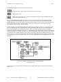
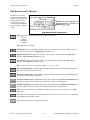
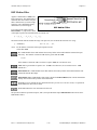
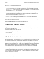
AT-DSP2200 Software Overview
The AT-DSP2200 board, working in conjunction with your personal computer, is a powerful numeric processor for
high-speed analysis of data arrays. The NI-DSP for LabVIEW for Windows software includes a number of utilities
and low-level memory management and data transfer VIs that facilitate communication between the DSP board and
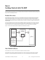
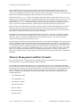
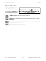
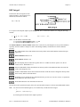
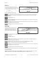
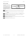
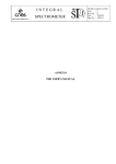
the host computer. Figure 1-1 is a block diagram of the software utilities and libraries that control the
AT-DSP2200. The DSP Library and the low-level memory management and data transfer functions reside and
execute on the board. You can customize the DSP Library to optimize performance, as described in Part 4,
Chapter 2, Getting Started with the NI-DSP Interface Utilities, of this manual. Your application programs and the
Interface Library, however, reside on the host PC.
PC
AT-DSP2200
AT or EISA Bus
User
Application
in LabVIEW
VI
Interface
(CIN)
DSP Software
DSP Hardware
Onboard Kernel,
DSP Board
Memory
Management,
Data Transfer
Functions
CPU
DSP Library
Onboard Memory
Interface
Library
(DSP.DLL)
Figure 1-1. Communication between the PC and the DSP Board
NI-DSP SRM for LabVIEW for Windows
1-1
Part 2: Introduction to the NI-DSP Analysis VIs
Introduction to the NI-DSP Analysis VIs
Part 2
The AT-DSP2200 can process large amounts of data, separately and distinctly from the host PC processor. The
board consists not only of a signal processing chip, but also memory where data that the board processes must
reside. The AT-DSP2200 does not have access to memory locations on the host PC. Therefore, you must download
all data from your application programs to DSP board memory before processing it.
The Interface Library, DSP.DLL, and the Code Interface Node (CIN) interface, which reside on the PC, serve as a
bridge between your application programs in LabVIEW and the DSP software running on the board. When you call
an NI-DSP Analysis VI, the VI passes the parameters to the CIN first, which then passes the parameters to the
Interface Library, DSP.DLL. The Interface Library determines what type of parameters are being passed, decides
how to set up the data in DSP board memory, and then calls the actual functions that will run on the board.
When a function on the DSP board processes data, it assumes the data is resident in DSP board memory. Because
transferring data between the PC and the DSP board slows down processing, none of the NI-DSP Analysis VIs
transfer data back and forth internally except the data transferring VIs. The NI-DSP Analysis VIs process the data
buffers that are already on the board and leave the results on the board.
If the data buffer you want to process using the DSP board is in PC memory, you must copy the data to the DSP
board before you call a function on the DSP board to process the data. To see the results, you must then copy the
data back to the PC. Several special NI-DSP Analysis VIs perform these transfers. For scalars, the NI-DSP
Analysis VIs automatically perform the transfer for you.
The representation of data buffers in the NI-DSP Analysis VIs is not the normal LabVIEW data array representation
because the data buffers indicate the data location on the DSP board instead of the PC address. A special structure,
called a DSP Handle Cluster, represents the data buffer on the DSP board from LabVIEW. The DSP Handle Cluster
is a coded DSP board memory address that indicates where the data buffer is on the DSP board. You must call the
DSP Allocate Memory VI to obtain a valid DSP Handle Cluster. Several VIs can manage the memory on the DSP
board. You can allocate and deallocate memory on the DSP board using these VIs. The next section, Memory
Management and Data Transfer, discusses the VIs used to allocate memory and transfer data buffers to and from the
DSP board.
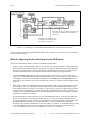
Memory Management and Data Transfer
This section describes how to manage memory on the DSP board from your LabVIEW application and how to
transfer data between your LabVIEW application and the DSP board.
The NI-DSP for LabVIEW package contains a set of VIs that manage memory space on the DSP board and help
improve data transfers between the DSP board and your application. There are VIs for allocating memory buffers on
the DSP board, for indexing into previously allocated buffers, for deallocating buffers and for copying data between
DSP and LabVIEW. The following VIs, described in greater detail in Part 3 of Chapter 2, NI-DSP Analysis VI
Reference, handle memory management on the DSP board and data transfers between the DSP board and your
LabVIEW application:
•
Copy Mem[DSP to DSP]
•
Copy Mem[DSP to LV]
•
Copy Mem[LV to DSP]
•
DSP Allocate Memory
•
DSP Free Memory
•
DSP Index Memory
•
DSP Init Memory
Part 2: Introduction to the NI-DSP Analysis VIs
1-2
NI-DSP SRM for LabVIEW for Windows
Part 2
Introduction to the NI-DSP Analysis VIs
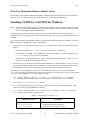
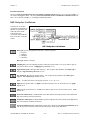
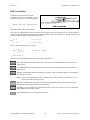
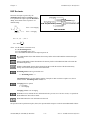
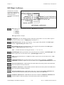
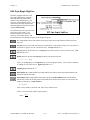
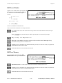
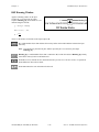
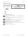
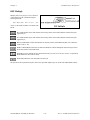
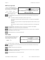
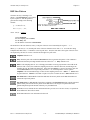
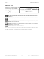
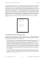
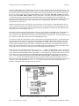
The DSP Allocate Memory VI allocates memory buffers on the DSP board and returns a DSP Handle Cluster, which
has two fields that uniquely describe this buffer–a DSP Handle and a size.
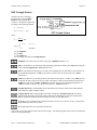
Figure 1-2. DSP Handle Cluster
DSP Handle is a 32-bit integer containing information that indicates the board on which the allocated buffer resides,
and an index into an onboard Memory Look Up Table (MLUT) that holds the actual DSP address of the buffer that
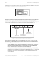
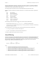
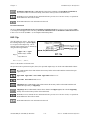
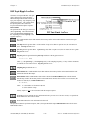
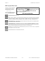
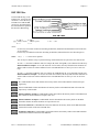
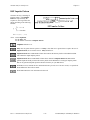
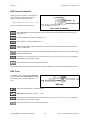
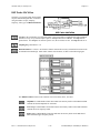
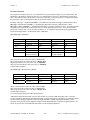
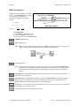
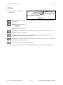
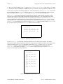
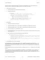
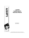
this handle represents. Figure 1-3 shows how a DSP Handle is encoded. The size field holds the number of
elements in this buffer. An element can be 4 bytes (for 32-bit floating-point data or long integer data) or 2 bytes (for
16-bit integer data) depending on the bytes per element selector used in the DSP Allocate Memory VI.
X
X
X
X
3
0
0
4
}
}
Index into the
MLUT of the
Owner DSP Board
Special Code
Board Number of
Owner DSP Board
Figure 1-3. The Hexadecimal Encoding of a Typical DSP Handle
The first four hexadecimal numbers (upper 16 bits) of the DSP Handle, shown in Figure 1-3, are a special value.
The interface code for a particular function that your application calls decodes these four hexadecimal numbers to
determine if the argument is a valid DSP Handle.
Notes: Do not change the value of a DSP Handle Cluster. Keep in mind that a DSP Handle Cluster is just an entry
of a table that indicates where the data buffer is on the DSP board. If you want to operate on part of the
data in that buffer, use the DSP Index Memory VI or the DSP Subset VI to obtain a new DSP Handle
Cluster to hold the part of the data. Then operate on the new DSP Handle Cluster.
The Memory Look-Up Table (MLUT) has only 128 entries. You can allocate only a total of 128 different
DSP Handle Clusters. Although you might have physical memory on the DSP board, you will get an error
message for not having enough memory if you already have 128 DSP Handle Clusters in use. Free the DSP
Handle Clusters that are not in use. The DSP Init Memory VI will free all DSP Handle Clusters on the
specified DSP board.
NI-DSP SRM for LabVIEW for Windows
1-3
Part 2: Introduction to the NI-DSP Analysis VIs
Introduction to the NI-DSP Analysis VIs
Part 2
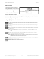
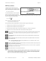
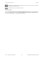
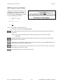
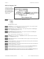
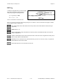
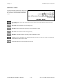
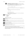
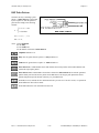
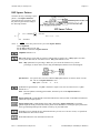
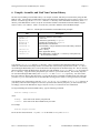
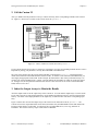
Figures 1-4 and 1-5 show how to allocate a DSP Handle Cluster of 2,048 4-byte-long elements on board 3. The
board number on which the buffer is allocated is important for determining the ownership of the buffer. When
making a VI call, the same DSP board on which the function is to execute must own all of the DSP Handle Clusters
or an error code is returned. Only the DSP Allocate Memory VI and few other VIs that do not have DSP Handle
Clusters as input parameters have a board slot parameter. VIs that have DSP Handle Clusters as input parameters
obtain the board slot information from their own DSP Handle Clusters. All of the DSP Handle Clusters should have
the same slot information, because the DSP VIs assume that all are executing on the same DSP board.
Figure 1-4. Front Panel–An Example of How to Allocate a DSP Handle Cluster
Figure 1-5. Block Diagram–An Example of How to Allocate a DSP Handle Cluster
For all of the NI-DSP Analysis VIs, the array data type is DSP Handle Cluster. Before you call any of these VIs,
call the DSP Allocate Memory VI to obtain a valid DSP Handle Cluster, which you then use as a reference to your
data buffer. The Analysis VIs assume that the data is already on the board and stores the results on the board. If you
want to copy data between the PC and the DSP board, use either the Copy Mem(LV to DSP) VI or the Copy
Mem(DSP to LV) VI to copy data back and forth.
If you use the DSP Allocate Memory VI in your program, use the DSP Free Memory VI to free buffers allocated
when you do not need them any more. The board holds these allocations in memory even after your application has
completed or you exit LabVIEW unless you execute the DSP Init Memory VI or reload the DSP Library. Thus, it is
important to free all buffers your application allocated before you exit the application or you may run out of memory
on the board.
Part 2: Introduction to the NI-DSP Analysis VIs
1-4
NI-DSP SRM for LabVIEW for Windows
Part 2
Introduction to the NI-DSP Analysis VIs
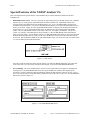
Special Features of the NI-DSP Analysis VIs
This section describes the special features of the NI-DSP Analysis VIs that make them different from other
LabVIEW VIs.
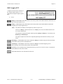
•
DSP Handle Cluster in/out. The way you specify the output data buffers for NI-DSP Analysis VIs is different
from the way you would specify output data buffers for other LabVIEW VIs. DSP Handle Clusters also
represent all the output data buffers in the NI-DSP Analysis VIs. To use valid DSP Handle Clusters for the
NI-DSP VI output data buffers, you must use the DSP Allocate Memory VI to obtain the DSP Handle Clusters
before you use them. Supply all of the output DSP Handle Clusters as inputs to tell the DSP board where the
output buffers are. Every output DSP Handle Cluster is identical to the corresponding input DSP Handle
Cluster. The two DSP Handle Clusters are internally connected. The output is an indicator. The input is a
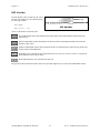
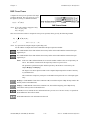
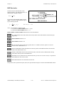
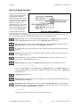
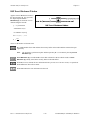
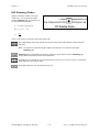
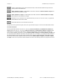
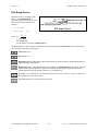
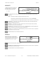
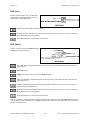
control. For example, in the DSP Add VI, shown in Figure 1-6, Z is the DSP Handle Cluster that indicates
where to store the results. You use Z in to connect to a valid DSP Handle Cluster that you previously allocated.
Z in tells the DSP board where the results will be stored. Z out is the location where the results have already
been stored. Because Z in and Z out are the same DSP Handle Cluster, you need to free only one of them when
you want to deallocate their DSP board buffer.
Figure 1-6. DSP Add VI
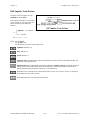
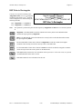
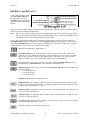
All of the controls and indicators in the NI-DSP Analysis VIs follow the Z in, Z out naming convention and
work in the same way as previously described in the example, except for the error in/error out cluster.
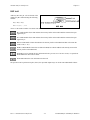
•
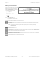
Error Handling. All of the NI-DSP Analysis VIs have an error input and an error output for managing and
reporting errors. The error in/error out cluster used by the NI-DSP VIs and many other high-level I/O
operations is a cluster containing a Boolean indicating whether the data should be treated as an error, a 32-bit
error code, and a descriptive string that usually contains the name of the source of the error. The error in/error
out cluster is shown in Figure 1-7.
Figure 1-7. The error in/error out Cluster
NI-DSP SRM for LabVIEW for Windows
1-5
Part 2: Introduction to the NI-DSP Analysis VIs
Introduction to the NI-DSP Analysis VIs
Part 2
The error in/error out cluster contains the following elements:
The boolean value is true if an error occurred, false if no error occurred.
code is the error code.
source is the source of the error. If an error occurs during execution, the VI sets source to the name
of the VI that produced the error.
Every VI checks error in first. If there is an error, the VI does not execute any DSP code but simply passes the
contents of error in to the error out cluster. If there is no error, the VI executes. One advantage of this error
in/error out design is that you can connect several I/O operations together so that, if an error occurs, subsequent VIs
do not perform undesired actions. DSP Free Memory will execute even if an error occurs. This ensures that
allocated buffers are freed even if an error occurred.
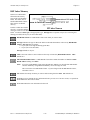
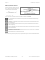
Another advantage of this error in/error out design is that you can establish the order of a set of operations, even if
there is no other data flow between the operations. Connecting the error out of the first VI to the error in of the
second VI establishes data flow and therefore execution order. You could do the same thing with a Sequence
structure, but with the error in/error out design, you can establish the order with all of the operations at the top level
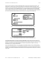
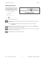
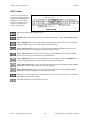
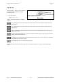
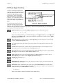
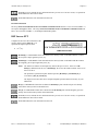
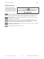
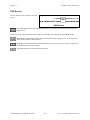
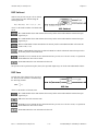
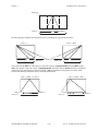
of the block diagram. For example, in Figure 1-8, you allocate DSP Handle Clusters X and Y as inputs, and you want
to free X and Y after the DSP Add VI has been executed. If you simply connect X to the DSP Free Memory VI as
shown in Figure 1-8, there is no sequential order between the DSP Add VI and the DSP Free Memory VI. If the DSP
Free Memory VI executes first, the DSP Add VI will receive an invalid handle because that DSP Handle Cluster was
deallocated.
Figure 1-8. An Example That Does Not Use error in/error out
for Sequencing VIs
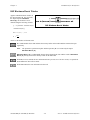
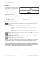
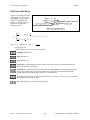
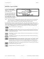
If you connect the VIs as shown Figure 1-9 instead, you ensure that the DSP Add VI executes before the DSP Free
Memory VI.
Part 2: Introduction to the NI-DSP Analysis VIs
1-6
NI-DSP SRM for LabVIEW for Windows
Part 2
Introduction to the NI-DSP Analysis VIs
error out of the Copy Mem(LV to DSP) VI is
connected to the error in of the DSP Free
Memory VI
error out of the DSP Add VI is
connected to the error in of the
Copy Mem(LV to DSP) VI
Figure 1-9. An Example of Using the error in/error out Cluster for Sequential VI Execution
For more information about the error in/error out cluster, refer to Chapter 2, Error Handler VIs, in the LabVIEW
Utility VI Reference Manual.
Hints for Improving the Execution Speed on the DSP Board
Check each of the following things to maximize your DSP board performance:
•
Allocate as many of the DSP Handle Clusters as you can before you operate on the data. Keep all data on the
DSP board until you finish all of the processing. Reduce the number of data transfers between the DSP board
and the PC as much as possible. The functions that run on the DSP board are very fast, but transferring data
between the DSP board and the PC and memory allocation slows the total processing performance.
•
Use the error in/error out cluster for sequencing VI execution. Be sure all of your VIs run in the correct
sequence. Use the error in/error out cluster to propagate the errors. If an error occurs, you can tell where the
error happens. You can use the LabVIEW error handler VIs in the Utility option of the Functions menu to
obtain pop-up error messages. Refer to the LabVIEW Utility VI Reference Manual for more information about
these VIs.
•
Many analysis routines on the DSP board can be performed in place; that is, the input and output array can be
the same array. This is very important to remember when you are processing large amounts of data. Large
32-bit floating-point arrays consume a lot of memory. If the results you want do not require that you keep the
original array or an intermediate array of data, perform analysis operations in place whenever possible. For
example, use the same DSP Handle Cluster for the input and output data buffers in your diagram in LabVIEW.
This will save your DSP board memory.
•
Several intermediate-level data acquisition VIs work with DSP Handle Clusters. These VIs can acquire data
and leave it on the board. You can use the NI-DSP Analysis VIs to operate on this data and then copy the
processed results back to the PC. In this way, you dramatically reduce the data transfer overhead between the
PC and the DSP board, and improve the overall performance. For more information about these data
acquisition VIs, refer to the LabVIEW Data Acquisition VI Reference Manual. An example that shows you how
to use a DSP Handle Cluster to acquire data and process this data on the DSP board can be found in the
DSP2200 subdirectory of the EXAMPLES subdirectory of your LabVIEW directory.
NI-DSP SRM for LabVIEW for Windows
1-7
Part 2: Introduction to the NI-DSP Analysis VIs
Introduction to the NI-DSP Analysis VIs
Part 2
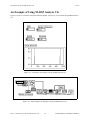
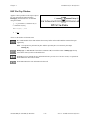
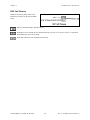
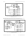
An Example of Using NI-DSP Analysis VIs
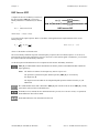
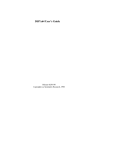
Figures 1-10 and 1-11 show the front panel and block diagram, respectively, of an example using NI-DSP Analysis
VIs.
Figure 1-10. Front Panel–An Example of Using NI-DSP Analysis VIs
Figure 1-11. Block Diagram–An Example of Using NI-DSP Analysis VIs
Part 2: Introduction to the NI-DSP Analysis VIs
1-8
NI-DSP SRM for LabVIEW for Windows
Part 2
Introduction to the NI-DSP Analysis VIs
This example shows you how to obtain the power spectrum of a sine wave signal. First, generate a sine wave that
you want to analyze using the LabVIEW Analysis VIs, then use the Copy Mem(LV to DSP) VI to copy the data of
this sine signal to the DSP board. Before you copy the data, you must call the DSP Allocate Memory VI to allocate
a DSP Handle Cluster that reserves a data buffer on the DSP board. Connect this DSP Handle Cluster to the
destination in terminal of the Copy Mem(LV to DSP) VI to indicate where the data will be stored on the DSP
board. After the data is copied to the DSP board, call the DSP Power Spectrum VI to perform a power spectrum on
the data. After you finish the analysis, the results are stored in the data buffer indicated by the DSP Handle Cluster
you previously allocated. If you want to see the results, call the Copy Mem(DSP to LV) VI to copy data back to
LabVIEW. Figure 1-10 shows the power spectrum of a sine wave. The last step is to call the DSP Free Memory VI
to free the DSP Handle Cluster that you allocated. This example connects all of the error out clusters of the
previous VIs to the error in clusters of the subsequent VIs to establish the proper sequence and to pass through an
error, should it occur, without executing the rest of the VIs.
NI-DSP SRM for LabVIEW for Windows
1-9
Part 2: Introduction to the NI-DSP Analysis VIs
Chapter 1
NI-DSP Analysis VI Reference Overview
This chapter contains an overview of the NI-DSP Analysis VIs and includes a list of the VIs. This chapter describes
how the NI-DSP Analysis VIs are organized and how to access them.
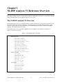
The NI-DSP Analysis VI Overview
The NI-DSP Analysis VIs are a set of high-performance VIs that efficiently process large blocks of numerical data
and perform numerically intensive computations. The NI-DSP Analysis VIs include numerical analysis, signal
generation, digital signal processing, digital filtering, and windowing operations that are suitable for simulation,
modeling, and sophisticated data processing.
The NI-DSP Analysis VIs are presented in alphabetical order in Chapter 2, NI-DSP Analysis VI Reference.
Table 1-1 lists these VIs by group.
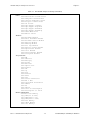
Table 1-1. The NI-DSP Analysis VI Groups
Signal Generation
DSP Sine Pattern
DSP Pulse Pattern
DSP Impulse Pattern
DSP Impulse Train Pattern
DSP Ramp Pattern
DSP Sinc Pattern
DSP Square Pattern
DSP Triangle Pattern
DSP Triangular Train
DSP Sawtooth Pattern
DSP Uniform White Noise
DSP Random Pattern
DSP Gaussian White Noise
Frequency Domain
DSP ReFFT
DSP Complex FFT
DSP Inverse FFT
DSP Power Spectrum
DSP Cross Power
DSP FHT
DSP Inverse FHT
DSP Zero Padder
Time Domain
DSP Convolution
DSP Deconvolution
DSP Correlation
DSP Decimate
DSP Derivative
DSP Integral
(continues)
NI-DSP SRM for LabVIEW for Windows
1-1
Part 3: NI-DSP Function Reference
NI-DSP Analysis VI Reference Overview
Chapter 1
Table 1-1. The NI-DSP Analysis VI Groups (Continued)
Filters
DSP Butterworth Coefficients
DSP Chebyshev Coefficients
DSP Inverse Chebyshev Coeff
DSP Elliptic Coefficients
DSP IIR Filter
DSP Equi-Ripple LowPass
DSP Equi-Ripple HighPass
DSP Equi-Ripple BandPass
DSP Equi-Ripple BandStop
DSP Parks-McClellan
DSP Median Filter
Windows
DSP Blackman Window
DSP Exact Blackman Window
DSP Blackman Harris Window
DSP Hanning Window
DSP Hamming Window
DSP Flat Top Window
DSP General Cosine Window
DSP Exponential Window
DSP Force Window
DSP Kaiser-Bessel Window
DSP Triangular Window
Array Functions
DSP Add
DSP Subtract
DSP Multiply
DSP Divide
DSP Absolute
DSP Square Root
DSP Product
DSP Sum
DSP Log
DSP Clip
DSP Reverse
DSP Shift
DSP Sort
DSP Linear Evaluation
DSP Max & Min
DSP Polynomial Evaluation
DSP Subset
DSP Set
DSP Unwrap
DSP Polar to Rectangular
DSP Rectangular to Polar
Memory Management
DSP Allocate Memory
Copy Mem(LV to DSP)
Copy Mem(DSP to LV)
Copy Mem(DSP to DSP)
DSP Free Memory
DSP Index Memory
DSP Init Memory
Part 3: NI-DSP Function Reference
1-2
NI-DSP SRM for LabVIEW for Windows
Chapter 1
NI-DSP Analysis VI Reference Overview
Table 1-1. The NI-DSP Analysis VI Groups (Continued)
Utility Functions
DSP Reset
DSP Load
DSP Start
DSP Timeout
DSP Custom
DSP DMA Copy(DSP to LV)
DSP DMA Copy(LV to DSP)
DSP Handle to Address
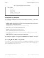
Analysis VI Organization
After installation, the NI-DSP Analysis VIs reside in the following VI library files (LabVIEW .LLB files) within
the DSP2200 option:
•
Signal Generation contains VIs that generate digital patterns.
•
Frequency Domain contains VIs that perform frequency domain transformations, frequency domain analysis,
and other transforms such as the Hartley transform.
•
Time Domain contains VIs that perform direct time series analysis of signals.
•
Filters contains VIs that perform IIR and FIR filtering functions.
•
Windows contains VIs that perform smoothing windowing.
•
Array contains VIs that perform arithmetic operations on arrays.
•
Memory Management contains VIs to perform allocating, indexing, copying, and freeing memory on the
AT-DSP2200 board.
•
Utility contains VIs for controlling the operation of the AT-DSP2200 board.
After installation, the eight analysis VI libraries appear in the Functions menu in the order shown in the preceding
list under the DSP2200 option. You can reorganize the folders and the VIs to suit your needs and applications.
Accessing the NI-DSP Analysis VIs
To access the analysis VIs from the block diagram window, choose DSP2200 from the Functions menu as shown in
Figure 1-1, proceed through the hierarchical menus, and select the VI you want. The icon corresponding to that VI
appears in the block diagram and is ready to be wired.
NI-DSP SRM for LabVIEW for Windows
1-3
Part 3: NI-DSP Function Reference
NI-DSP Analysis VI Reference Overview
Chapter 1
Figure 1-1. Choosing DSP2200 from the Functions Menu
About the Fast Fourier Transform (FFT)
The VIs in the Frequency Domain group are based upon the discrete implementation and optimization of the Fourier
Transform integral. The Discrete Fourier Transform (DFT) of a complex sequence X containing n elements is
obtained using the following formula:
n-1
Y[i] = ∑ X[k] * exp (-j2π ik / n),
for i = 0, 1, …, n-1
k=0
where Y[i] is the ith element of the DFT of X and j =
-1.
√
The DFT of X also results in a complex sequence Y of n elements. Similarly, the Inverse Discrete Fourier
Transform (IDFT) of a complex sequence Y containing n elements is obtained using the following formula:
n-1
X[i] = (1/n) ∑ Y[k] * exp (j2π ik / n),
for i = 0, 1, …, n-1
k=0
where X[i] is the ith element of the IDFT of Y and j =
Part 3: NI-DSP Function Reference
√ -1.
1-4
NI-DSP SRM for LabVIEW for Windows
Chapter 1
NI-DSP Analysis VI Reference Overview
The discrete implementation of the DFT is a numerically intense process. However, it is possible to implement a
fast algorithm when the size of the sequence is a power of two. These algorithms are known as FFTs, and can be
found in many introductory digital signal processing (DSP) texts.
The resulting complex FFT sequence has the conventional DSP format as described in this section.
If there are n number of elements in the complex sequence and k = n/2, then the output of the FFT is organized as
follows:
Y[0]
Y[1]
Y[2]
:
Y[k-1]
Y[k]
Y[k+1]
:
Y[n-2]
Y[n-1]
DC component
Positive first harmonic
Positive second harmonic
:
Positive k-1 harmonic
Nyquist frequency
Negative k-1 harmonic
:
Negative second harmonic
Negative first harmonic
The following conventions and restrictions apply to the VIs in the Frequency Domain folder:
•
All arrays must be a power of two: n = 2m, m = 1, 2, 3, …, 24 (limited by onboard memory).
•
Complex sequences are manipulated using two arrays. One array represents the real elements. The other array
represents the imaginary elements.
The following notation is used to describe the FFT operations performed in the Frequency Domain class:
•
Y = FFT {X}, the sequence Y is the FFT of the sequence X.
•
Y = FFT-1 {X}, the sequence Y is the inverse FFT of the sequence X.
X is usually a complex array but can be treated as a real array.
About Filtering
All of the VIs in the Filters group are digital filters that can be represented by the computational algorithm that best
describes the relationship between the input and output discrete time sequences. This computational algorithm is
referred to as the Linear Constant Coefficient Difference Equation. This equation relates the input and output by the
basic operations of addition, delay and multiplication. The following equation relates the input and output
sequences x and y, respectively at the discrete time instant n:
i = N-1
i = M-1
i=0
i=1
a(0)*y(n) = ∑ (x[n-i]*b(i)) - ∑ (y[n-i]*a(i))
(a)
where :
x is the discrete time input signal to the system represented by the filter
y is the discrete time output signal of the system represented by the filter
a is the set of coefficients applied to the input in the linear difference equation and represent the
multiplication factors for delays. The equation suggests that there are N such coefficients.
b is the set of coefficients applied to the output in the linear difference equation and represent the
multiplication factors for delays. The equation suggests that there are M such coefficients.
NI-DSP SRM for LabVIEW for Windows
1-5
Part 3: NI-DSP Function Reference
NI-DSP Analysis VI Reference Overview
Chapter 1
The set of coefficients a and b are often referred to as the numerator and denominator coefficients, respectively.
Another common way to refer to them is as the feedforward and feedback coefficients. This is due to the
mathematical derivation that led to equation a. Refer to Discrete-Time Signal Processing by Oppenheim and
Schafer for more information. Another frequent assumption is that a(0)=1.0. For example, let us assume M = 4,
N = 4 and n = 2. Using the filtering equation produces:
a(0)*y(2) = b(0)*x(2) + b(1)*x(1) + b(2)* x(0) + b(3)* x(-1) - a(1)*y(1) - a(2)*y(0) - a(3)*y(-1)
(b)
The filtering equation suggests that in order to compute the value of the output at n = 2, you not only need the
coefficients that represent the filter that is producing this output sequence, but also the value of the current input and
output, the values of the input and output one time unit ago, the values of the input and output two time units ago,
and the values of the input and output three time units ago. You need some “history” about the previous outputs of
the filter as well as the previous inputs to the filter. The amount of history (number of previous output and input
samples) depends on the lengths of the arrays a and b (filter coefficients arrays).
At time n = 0, it is important to note that the filtering equation becomes:
a(0)*y(0) = b(0)*x(0) + b(1)*x(-1) + b(2)* x(-2) + b(3)* x(-3) - a(1)*y(-1) - a(2)*y(-2) - a(3)*y(-3)
(c)
Thus, for the function filter to properly operate as of time n = 0, you need to supply some history about previous
behavior. The filter function then updates the history as time goes on, keeping track of previous input values and
corresponding outputs. This history, at time n = 0, is referred to as the initial conditions on the input and output of
the filter.
Digital filters fall into two classes–Infinite Impulse Response filters (IIR filters) and Finite Impulse Response filters
(FIR filters). Notice that IIR filters are represented by equation (a) while the FIR filters can be represented by the
same equation provided all a's are zero except for a(0) as shown in the following equation:
i=N
a(0)*y(n) = ∑ (x[n-i]*b(i))
(d)
i=0
The NI-DSP Analysis VIs have a set of VIs that implement IIR and FIR filters. Because all digital filters are
approximations of their analog design counterparts, there are several techniques for designing a digital filter.
For the IIR filter design, the NI-DSP Analysis VIs have four approaches representing four different techniques of
obtaining digital filter specifications (coefficients to equation (a))–Butterworth, Chebyshev, inverse Chebyshev, and
elliptic techniques. With each design technique, you can obtain the coefficients for lowpass, highpass, bandpass,
and bandstop filters from the respective NI-DSP Analysis VIs.
For the FIR filters, the NI-DSP Analysis VIs allow the design of a multiband FIR linear phase filter using the ParksMcClellan algorithm. The frequency response in each band has equal ripples that can be adjusted by a weighting
factor. For more information, please refer to Digital Filter Design by Parks and Burrus, or "A Computer Program
for Designing Optimum FIR Linear Phase Digital Filters," by McClellan, Parks, and Rabiner.
The IIR VIs generate filter coefficients that represent the a's and b's in the equations a and b. No filtering is actually
performed. The IIR filter design coefficients all have a(0) = 1.0. You can use the general-purpose VI that accepts
filter coefficients, initial conditions on the input and output sequences, and an input sequence to filter any of the
filter specifications. This VI filters the input sequence and provides the final conditions on the output and input of
the filter.
About Windowing
Almost every application requires you to use finite length signals. This requires that continuous signals be
truncated, using a process called windowing.
Part 3: NI-DSP Function Reference
1-6
NI-DSP SRM for LabVIEW for Windows
Chapter 1
NI-DSP Analysis VI Reference Overview
The simplest window is a rectangular window. Because this window requires no special effort it is commonly
referred to as the no window option. Remember, however, that a discrete signal and its spectrum is always affected
by a window. Let x[n] be a digitized time-domain waveform that has a finite length of n. w[n] is a window
sequence of n points. The windowed output is calculated as follows:
y[i] = x[i] * w[i]
(1)
If X, Y, and W are the spectra of x, y, and w, respectively, the time-domain multiplication in formula 1 is equivalent
to the convolution shown as follows:
Y[k] = X[k] Θ W[k].
(2)
Convolving with the window spectrum always distorts the original signal spectrum in some way. A window
spectrum consists of a big mainlobe and several sidelobes.
The mainlobe is the primary cause of lost frequency resolution. When two signal spectrum lines are too close to
each other, they may fall in the width of the mainlobe, causing the output of the windowed signal spectrum to have
only one spectrum line. Use a window with a narrower mainlobe to reduce the loss of frequency resolution. It has
been shown that a rectangular window has the narrowest mainlobe, so that it provides the best frequency resolution.
The sidelobes of a window function affect frequency leakage. A signal spectrum line will leak into the adjacent
spectrum if the sidelobes are large. Once again, the leakage results from the convolution process. Select a window
with relatively smaller sidelobes to reduce spectral leakage. Unfortunately, a narrower mainlobe and smaller
sidelobes are mutually exclusive. For this reason, selecting a window function is application dependent. An
example of a windowed spectrum in the continuous case is shown in Figure 1-2.
*
Signal Spectrum
Window Spectrum
Windowed Signal Spectrum
Figure 1-2. Spectral Leakage Demonstrated Using Convolution
The original signal spectrum is convolved with the window spectrum and the output is a smeared version of the
original signal spectrum. In this example, you can still see four distinctive peaks from the original signal, but each
peak is smeared and the frequency leakage effect is clear.
NI-DSP SRM for LabVIEW for Windows
1-7
Part 3: NI-DSP Function Reference
NI-DSP Analysis VI Reference Overview
Chapter 1
Window definitions used in National Instruments analysis libraries are designed in such a way that the window
operations in the time domain are exactly equivalent to the operations of the same window in the frequency domain.
To meet this requirement, the windows are not symmetrical in the time domain, that is:
w[0] ≠ w[N-1]
(3)
where N is the window length. They are usually symmetrical in the frequency domain, however. For example, the
Hamming window definition uses the formula:
w[i] = 0.54 - 0.46 cos(2πi/N)
(4)
Other manufacturers may use a slightly different definition, such as:
w[i] = 0.54 - 0.46 cos(2πi/N-1)
(5)
The difference is small if N is large.
Formula 4 is not symmetrical in the time domain, but it ensures that the time domain windowing is equivalent to the
frequency domain windowing. If you want to have a perfectly symmetrical sequence in the time domain, you must
write your own windowing function using formula 5.
The choice of a window depends on the application. For most applications, the Hamming or Hanning windows
deliver good performance.
Part 3: NI-DSP Function Reference
1-8
NI-DSP SRM for LabVIEW for Windows
Chapter 2
NI-DSP Analysis VI Reference
This chapter contains a brief explanation of each NI-DSP Analysis VI . The VIs are arranged alphabetically.
Copy Mem(DSP to DSP)
Copies a buffer of data from the Source
buffer on the DSP board that is referred to
by a DSP Handle Cluster to the destination
buffer on the DSP board, which is referred
to by another DSP Handle Cluster. Source
and destination buffers should be on the
same DSP board.
To copy data correctly from one DSP
buffer to another DSP buffer, you must set the data type to the appropriate type to indicate what kind of data is on
the DSP board. The VI has three data types–32-bit floating-point data, 16-bit short integer data, and 32-bit long
integer data.
Source is a DSP Handle Cluster that indicates the memory buffer on the DSP board that contains the
data that you want to copy to the destination.
data type indicates the type of data that Source contains. The VI has three data types:
0: 32-bit floating-point data.
1: 16-bit short integer data.
2: 32-bit long integer data.
data type defaults to 32-bit floating-point data.
Destination in is a DSP Handle Cluster that indicates the destination memory buffer on the DSP board
that will contain the data copied from source buffer.
Destination out is a DSP Handle Cluster that is identical to the Destination in, but with the source
buffer data already copied to the memory buffer on the DSP board.
error in (no error) contains the error information from a previous VI. If an error occurs, it is passed out
error out and no other calls are made.
error out contains the error information for this call.
NI-DSP SRM for LabVIEW for Windows
2-1
Part 3: NI-DSP Function Reference
NI-DSP Analysis VI Reference
Chapter 2
Copy Mem(DSP to LV)
Copies an entire or partial buffer
of data according to the
entire/partial copy selector from
the Source buffer on the DSP
board that is referred to by a DSP
Handle Cluster to the destination
buffer in LabVIEW.
To copy data correctly from the
DSP board to LabVIEW, you
must indicate what type of data is
stored in the Source buffer on the DSP board. You must set the destination type to the appropriate type and wire to
the corresponding destination terminal. The VI has three destination types–float (32-bit), short (16-bit), and long
(32-bit). To copy different types of data, you must wire to the appropriate destination terminal that corresponds to
the destination type you choose. Remember, you must wire only one kind of destination terminal.
If you set the entire/partial copy selector to entire copy, all the data in the Source buffer will be copied back to the
destination without considering the values of offset and size. Otherwise, only the number of size the data in the
Source buffer, starting from the offset, will be copied back to the destination.
entire/partial copy selector has two types: entire copy and partial copy. It defaults to entire copy.
0: entire copy.
1: partial copy.
Source is a DSP Handle Cluster that indicates the memory buffer on the DSP board which contains the
data that you want copy to the destination in LabVIEW.
destination type indicates the type of the destination data on the DSP board. It has three options:
0: 32-bit floating-point.
1: 16-bit short integer.
2: 32-bit long integer.
destination type defaults to 32-bit floating point.
offset indicates where to start to copy data from the Source buffer on the DSP board to the destination
buffer in the LabVIEW. offset defaults to 0. This parameter is ignored when entire/partial copy
selector is set to entire copy.
size indicates how much data to copy from the Source buffer on the DSP board to the destination buffer
in LabVIEW. size defaults to 0. If offset plus size is greater than the number of elements in the Source
buffer, the VI returns an error. This parameter is ignored when entire/partial copy selector is set to
entire copy.
destination(float) is the terminal to which you should wire the destination buffer if the data you want to
copy is 32-bit floating-point data array.
destination(long) is the terminal to which you should wire the destination buffer if the data you want to
copy is 32-bit long data array.
destination(short) is the terminal to which you should wire the destination buffer if the data you want to
copy is 16-bit short data array.
error in (no error) contains the error information from a previous VI. If an error occurs, it is passed out
error out and no other calls are made.
error out contains the error information for this call.
Part 3: NI-DSP Function Reference
2-2
NI-DSP SRM for LabVIEW for Windows
NI-DSP Analysis VI Reference
Chapter 2
Copy Mem(LV to DSP)
Copies a buffer of data from the source
buffer in LabVIEW to the destination
buffer on the DSP board, which is referred
to by a DSP Handle Cluster.
The source buffer can contain one of three
kinds of data–float (32-bit), short
(16-bit), and long (32-bit). To copy
different types of data, you must wire to the
appropriate source terminal. You must
wire only one kind of source terminal. The
destination buffer must be large enough to contain all of the data from the source buffer.
source(float) is the terminal to which you should wire the source buffer if the data you want to copy is
32-bit floating point data array.
source(long) is the terminal to which you should wire the source buffer if the data you want to copy is
32-bit long data array.
source(short) is the terminal to which you should wire the source buffer if the data you want to copy is
16-bit short data array.
Destination in is a DSP Handle Cluster that indicates the destination memory buffer on the DSP board
that will contain the data copied from the LabVIEW source buffer.
Destination out is a DSP Handle Cluster that is identical to Destination in, but with the source buffer
data already copied to the memory buffer on the DSP board.
error in (no error) contains the error information from a previous VI. If an error occurs, it is passed out
error out and no other calls are made.
error out contains the error information for this call.
Part 3: NI-DSP Function Reference
2-3
NI-DSP SRM for LabVIEW for Windows
Chapter 2
NI-DSP Analysis VI Reference
DSP Absolute
Find the absolute value of input array X. The ith
element of the output array Y is obtained using
the following formula:
Y(i) = |X(i) |.
for i = 0, 1, 2, … , n-1
where n is the number of elements in X.
X is a DSP Handle Cluster that indicates the memory buffer on the DSP board that contains the input
signal array X.
Y in is a DSP Handle Cluster that indicates the memory buffer on the DSP board that will contain the
absolute results of X(i).
Y out is a DSP Handle Cluster that is identical to Y in, but with the absolute results already stored in the
memory buffer on the DSP board.
error in (no error) contains the error information from a previous VI. If an error occurs, it is passed out
error out and no other calls are made.
error out contains the error information for this call.
The operation can be performed in place; that is, the input and output arrays can be the same DSP Handle Cluster.
NI-DSP SRM for LabVIEW for Windows
2-4
Part 3: NI-DSP Function Reference
NI-DSP Analysis VI Reference
Chapter 2
DSP Add
Add array X to array Y. The ith element of the
output array Z is obtained using the following
formula:
Z(i) = X(i) + Y(i).
for i = 0, 1, 2, … , n-1
where n is the smaller number of elements in X and Y.
X is a DSP Handle Cluster that indicates the memory buffer on the DSP board that contains the input
signal array X.
Y is a DSP Handle Cluster that indicates the memory buffer on the DSP board that contains the input
signal array Y.
Z in is a DSP Handle Cluster that indicates the memory buffer on the DSP board that will contain the
results of X(i) + Y(i).
Z out is a DSP Handle Cluster that is identical to Z in, but with the added results already stored in the
memory buffer on the DSP board.
error in (no error) contains the error information from a previous VI. If an error occurs, it is passed out
error out and no other calls are made.
error out contains the error information for this call.
The operation can be performed in place; that is, the input and output arrays can be the same DSP Handle Cluster.
Part 3: NI-DSP Function Reference
2-5
NI-DSP SRM for LabVIEW for Windows
Chapter 2
NI-DSP Analysis VI Reference
DSP Allocate Memory
Allocates a block of memory buffer on
the DSP board specified by slot and
returns a DSP Handle Cluster that
contains the coded DSP board memory
and the number of elements in this
buffer.
The number of bytes allocated for this
buffer depends on size and
bytes/element selector. If bytes/element selector selects 4 bytes, then the number of bytes = size*4. If
bytes/element selector selects 2 bytes, then the number of bytes = size*2.
The allocation routines on the board assure alignment to the nearest 4-byte boundary ≥ number of bytes to guarantee
memory alignment on 4-byte addresses. For example, if you request to allocate a buffer of size 1,022 or 1,024 bytes,
the allocation routines allocate 1,024 bytes in both cases.
slot is the board ID number. slot defaults to 3.
size is the number of elements to allocate for this buffer. size defaults to 0.
bytes/element selector specifies the number of bytes per element. It has two options:
0: 4 bytes.
1: 2 bytes.
bytes/element selector defaults to 4 bytes.
DSP Handle Cluster indicates the allocated memory buffer on the DSP board.
error in (no error) contains the error information from a previous VI. If an error occurs, it is passed out
error out and no other calls are made.
error out contains the error information for this call.
NI-DSP SRM for LabVIEW for Windows
2-6
Part 3: NI-DSP Function Reference
NI-DSP Analysis VI Reference
Chapter 2
DSP Blackman Window
Applies a Blackman window to the input
sequence X. If Y represents the output
sequence Blackman{X}, the elements of Y
are obtained from the following formula:
yi = xi [0.42 - 0.50 cos(w)
+ 0.08 cos(2w)]
for i = 0, 1, 2, … , n-1 ,
w =
2πi
,
n
where n is the number of elements in X.
X is a DSP Handle Cluster that indicates the memory buffer on the DSP board that contains the input
signal array.
Note:
The operation is performed in place and the input array X is overwritten by the output
Blackman {X}.
Blackman {X} is a DSP Handle Cluster that is identical to X, but with the results of Blackman {X}
already stored in the memory buffer on the DSP board.
error in (no error) contains the error information from a previous VI. If an error occurs, it is passed out
error out and no other calls are made.
error out contains the error information for this call.
Part 3: NI-DSP Function Reference
2-7
NI-DSP SRM for LabVIEW for Windows
Chapter 2
NI-DSP Analysis VI Reference
DSP Blackman Harris Window
Applies a Blackman Harris window to
the input sequence X. If Y represents
the output sequence Blackman
Harris{X}, the elements of Y are
obtained using the following formula:
yi = xi [0.42323 - 0.49755 cos(w)
+0.07922 cos(2w)]
for i = 0, 1, 2, … , n-1
w =
2πi
,
n
where n is the number of elements in X.
X is a DSP Handle Cluster that indicates the memory buffer on the DSP board that contains the input
signal array.
Note:
The operation is performed in place and the input array X is overwritten by the output
Blackman Harris {X}.
Blackman Harris {X} is a DSP Handle Cluster that is identical to X, but with the results of Blackman
Harris {X} already stored in the memory buffer on the DSP board.
error in (no error) contains the error information from a previous VI. If an error occurs, it is passed out
error out and no other calls are made.
error out contains the error information for this call.
NI-DSP SRM for LabVIEW for Windows
2-8
Part 3: NI-DSP Function Reference
NI-DSP Analysis VI Reference
Chapter 2
DSP Butterworth Coefficients
Generates the set of filter
coefficients to implement an
IIR filter as specified by the
Butterworth filter model.
You can then pass these
coefficients to the DSP IIR
Filter VI to filter a sequence
of data.
filter type specifies the passband of the filter. It has four options:
0: lowpass.
1: highpass.
2: bandpass.
3: bandstop.
filter type defaults to lowpass.
sampling freq : fs is the sampling frequency and must be greater than 0. If it is less than or equal to
zero, the VI returns an error. sampling freq : fs defaults to 1.0.
high cutoff freq: fh is the high cutoff frequency. The VI ignores this parameter when filter type is
lowpass. high cutoff freq: fh defaults to 0.45.
low cutoff freq: fl is the low cutoff frequency. The VI ignores this parameter when filter type is
highpass. low cutoff freq: fl defaults to 0.125.
Note: fh and fl must observe the Nyquist criterion:
0 ≤ fl ≤ fh ≤ fs /2.
Forward Coefficients in is a DSP Handle Cluster that indicates the memory buffer on the DSP board
that will contain the forward coefficients.
Feedback Coefficients in is a DSP Handle Cluster that indicates the memory buffer on the DSP board
that will contain the feedback coefficients.
Forward Coefficients out is a DSP Handle Cluster that is identical to the Forward Coefficients in, but
with the forward coefficients already stored in the memory buffer on the DSP board.
Feedback coefficients out is aDSP Handle Cluster that is identical to the Feedback Coefficients in, but
with the feedback coefficients already stored in the memory buffer on the DSP board.
order must be greater than zero. If order is less than or equal to zero, the VI returns an error. order
defaults to 2.
error in (no error) contains the error information from a previous VI. If an error occurs, it is passed out
error out and no other calls are made.
error out contains the error information for this call.
Part 3: NI-DSP Function Reference
2-9
NI-DSP SRM for LabVIEW for Windows
Chapter 2
NI-DSP Analysis VI Reference
Parameter Discussion
The arrays Forward Coefficients in/out and Feedback Coefficients in/out must have a size of at least (order + 1)
for lowpass and highpass filters. The arrays Forward Coefficients in/out and Feedback Coefficients in/out must
have a size of at least (2*order + 1) for bandpass and bandstop filters.
DSP Chebyshev Coefficients
Generates the set of filter
coefficients to implement an
IIR filter as specified by the
Chebyshev filter model.
You can then pass
coefficients to the DSP IIR
Filter VI to filter a sequence
of data.
filter type specifies the passband of the filter. It has four options:
0: lowpass.
1: highpass.
2: bandpass.
3: bandstop.
filter type defaults to lowpass.
sampling freq : fs is the sampling frequency and must be greater than 0. If it is less than or equal to
zero, the VI returns an error. sampling Freq : fs defaults to 1.0.
high cutoff freq: fh is the high cutoff frequency. The VI ignores this parameter when filter type is
lowpass. high cutoff freq: fh defaults to 0.45.
low cutoff freq: fl is the low cutoff frequency. The VI ignores this parameter when filter type is
highpass. low cutoff freq: fl defaults to 0.125.
Note:
fh and fl must observe the Nyquist criterion: 0 ≤ fl ≤ fh ≤ fs /2.
ripple must be greater than 0. If ripple is less than or equal to zero, the VI returns an error. ripple
defaults to 0.1.
order must be greater than zero. If order is less than or equal to zero, the VI returns an error. order
defaults to 2.
Forward Coefficients in is a DSP Handle Cluster that indicates the memory buffer on the DSP board
that will contain the forward coefficients.
Feedback Coefficients in is a DSP Handle Cluster that indicates the memory buffer on the DSP board
that will contain the feedback coefficients.
Forward Coefficients out is a DSP Handle Cluster that is identical to the Forward Coefficients in, but
with the forward coefficients already stored in the memory buffer on the DSP board.
NI-DSP SRM for LabVIEW for Windows
2-10
Part 3: NI-DSP Function Reference
Chapter 2
NI-DSP Analysis VI Reference
Feedback Coefficients out is a DSP Handle Cluster that is identical to the Feedback Coefficients in,
but with the feedback coefficients already stored in the memory buffer on the DSP board.
error in (no error) contains the error information from a previous VI. If an error occurs, it is passed out
error out and no other calls are made.
error out contains the error information for this call.
Parameter Discussion
The arrays Forward Coefficients in/out and Feedback Coefficients in/out have to have a size of at least (order +
1) for lowpass and highpass filters.The arrays Forward Coefficients in/out and Feedback Coefficients in/out have
to have a size of at least (2*order + 1) for bandpass and bandstop filters.
DSP Clip
Clips the input array values. The range of
the resulting output array is [lower:upper].
Let Y represent the output array. The ith
element of the resulting array is obtained by
using the following formulas:
upper if X(i) > upper
lower if X(i) < lower
Y(i) =
X(i) otherwise
for i = 0, 1, 2, …, size-1 ,
where n is the number of elements in X.
The operation can be performed in place; that is, the input and output arrays can be the same DSP Handle Cluster.
X is a DSP Handle Cluster that indicates the memory buffer on the DSP board that contains the input
signal array X.
upper limit. upper limit
≥ lower limit. upper limit defaults to 1.0.
lower limit. lower limit defaults to 0.0.
Clipped{X} in is a DSP Handle Cluster that indicates the memory buffer on the DSP board that will
contain the output array of Clipped{X}.
Clipped{X} out is a DSP Handle Cluster that is identical to Clipped {X} in, but with the Clipped{X}
already stored in the memory buffer on the DSP board.
error in (no error) contains the error information from a previous VI. If an error occurs, it is passed out
error out and no other calls are made.
error out contains the error information for this call.
NI-DSP SRM for LabVIEW for Windows
2-11
Part 3: NI-DSP Function Reference
NI-DSP Analysis VI Reference
Chapter 2
DSP Complex FFT
Computes the Fast Fourier transform of
the complex input sequence X. If Y
represents the complex output sequence,
then:
Y = F{X}.
Re{X} is a DSP Handle Cluster that indicates the memory buffer on the DSP board that contains the real
part of the input signal array X.
Im{X} is a DSP Handle Cluster that indicates the memory buffer on the DSP board that contains the
imaginary part of input signal array X.
Notes: The number of elements for the input array must be a power of 2.
If the size of Re{X} is different from the size of Im{X}, the VI uses the smaller number as the
size of the Complex FFT.
The operation is performed in place and the input array Re{X} and Im{X} is overwritten by the
Re FFT{X} and Im FFT{X}.
The largest complex FFT that can be computed depends upon the amount of memory on your
board.
Re FFT{X} is a DSP Handle Cluster that is identical to Re{X}, but with the real part of FFT{X}already
stored in the memory buffer on the DSP board.
Im FFT{X} is a DSP Handle Cluster that is identical to Im{X}, but with the imaginary part of
FFT{X}already stored in the memory buffer on the DSP board.
error in (no error) contains the error information from a previous VI. If an error occurs, it is passed out
error out and no other calls are made.
error out contains the error information for this call.
Part 3: NI-DSP Function Reference
2-12
NI-DSP SRM for LabVIEW for Windows
Chapter 2
NI-DSP Analysis VI Reference
DSP Convolution
Computes the convolution of the input
sequences X and Y. The convolution Cxy(t), of
the signals x(t) and y(t), is defined as follows:
∞
Cxy(t) = x(t) * y(t) = ∫ x(τ) y(t-τ) dτ ,
-∞
where the symbol * denotes convolution.
For the discrete implementation of the convolution, let Cxy represent the output sequence X * Y, n be the number of
elements in the input sequence X, and m be the number of elements in the input sequence Y. Assuming that indexed
elements of X and Y that lie outside their range are zero,
xi = 0,
i < 0 or i ≥ n
yj = 0,
j < 0 or j ≥ m,
and
then you obtain the elements of Cxy using:
n-1
Cxy i =
∑ x k yi-k
for i = 0, 1, 2, …, size-1 ,
k=0
size = n + m - 1,
where size is the total number of elements in the output sequence X * Y.
X is a DSP Handle Cluster that indicates the memory buffer on the DSP board that contains the input
signal array X.
Y is a DSP Handle Cluster that indicates the memory buffer on the DSP board that contains the input
signal array Y.
Cxy in is a DSP Handle Cluster that indicates the memory buffer on the DSP board that will contain the
convolution of X with Y.
Note: The size of Cxy in must be (n+m-1) elements long. n is the size of X, m is the size of Y. You
cannot perform the operation in place.
Cxy out is a DSP Handle Cluster that is identical to the Cxy in but with the convolution of X and Y
already stored in the memory buffer on the DSP board.
error in (no error) contains the error information from a previous VI. If an error occurs, it is passed out
error out and no other calls are made.
error out contains the error information for this call.
NI-DSP SRM for LabVIEW for Windows
2-13
Part 3: NI-DSP Function Reference
NI-DSP Analysis VI Reference
Chapter 2
DSP Correlation
Computes the cross correlation of the input
sequences X and Y. The cross correlation Rxy(t)
of the signals x(t) and y(t) is defined as follows:
∞
R xy(t) = x(t) ⊗ y(t) =
∫ x(t) y(t+t)
dt ,
-∞
where the symbol ⊗ denotes correlation.
For the discrete implementation of the correlation, let Rxy represent the output sequence X ⊗ Y, n be the number of
elements in the input sequence X, and m be the number of elements in the input sequence Y. You then obtain the
elements of R xy using the following formula:
n-1
R xy i =
∑ x[k] y[k+m-1]
for i = 0, 1, 2, …, m+n-1 ,
k=0
X is a DSP Handle Cluster that indicates the memory buffer on the DSP board that contains the input
signal array X.
Y is a DSP Handle Cluster that indicates the memory buffer on the DSP board that contains the input
signal array Y.
Rxy in is a DSP Handle Cluster that indicates the memory buffer on the DSP board that will contain the
correlation results.
Note: The size of Rxy in must be at least (n+m-1) elements long. n is the size of X, m is the size
of Y.
Rxy out is a DSP Handle Cluster that is identical to the Rxy in, but with the correlation of X and Y
already stored in the memory buffer on the DSP board.
Note: If X and Y are the same array, an auto correlation is performed, otherwise, a cross correlation is
performed. You cannot perform the operation in place.
error in (no error) contains the error information from a previous VI. If an error occurs, it is passed out
error out and no other calls are made.
error out contains the error information for this call.
Part 3: NI-DSP Function Reference
2-14
NI-DSP SRM for LabVIEW for Windows
Chapter 2
NI-DSP Analysis VI Reference
DSP Cross Power
Computes the cross power spectrum of the input
sequences X and Y. The cross power, Sxy(f), of
the signals x(t) and y(t) is defined as follows:
S xy(f) = X*(f)Y(f)
where X*(f) is the complex conjugate of X(f),
X(f) = F{x(t)}, and
Y(f) = F{y(t)}.
This VI uses the FFT routine to compute the cross power spectrum, that is given by the following formula:
S xy =
n = 2k
1
F*{X} F{Y} ,
n2
for k = 1, 2, 3, …, 23,
where S xy represents the complex output sequence Sxy, and
n is the number of samples that can accommodate both input sequences X and Y.
X is a DSP Handle Cluster that indicates the memory buffer on the DSP board that contains the input
signal array X.
Y is a DSP Handle Cluster that indicates the memory buffer on the DSP board that contains the input
signal array Y.
Notes: If the size of X is different than Y, the VI uses the smaller number as the size of input arrays X
and Y. The number of elements for the input arrays must be a power of two.
The operation is performed in place and the input arrays X and Y are overwritten by the
outputs Re{Sxy} and Im{Sxy}.
The largest Cross Power Spectrum that can be computed depends upon the amount of memory
in your DSP board.
This VI allocates a temporary workspace on the DSP board equal to the size of the input signal
array.
Re{Sxy} is a DSP Handle Cluster that is identical to X, but with the real part of Sxy already stored in the
memory buffer on the DSP board.
Im{Sxy} is a DSP Handle Cluster that is identical to Y, but with the imaginary part of Sxy already
stored in the memory buffer on the DSP board.
error in (no error) contains the error information from a previous VI. If an error occurs, it is passed out
error out and no other calls are made.
error out contains the error information for this call.
NI-DSP SRM for LabVIEW for Windows
2-15
Part 3: NI-DSP Function Reference
NI-DSP Analysis VI Reference
Chapter 2
DSP Custom
Use this VI as the interface to
call your own custom functions
written on the DSP board from
LabVIEW. For more details
about how to use this VI, refer
to Part 4, NI-DSP Interface
Utilities, of this manual.
slot is the board ID number. slot defaults to 3.
function code indicates which function on the DSP board LabVIEW is calling. function code defaults
to 0.
Array of Handles in is an array of DSP Handle Clusters that hold all of the references to the input and
output data buffers used in your custom functions on the DSP board.
Array of SGL Scalars in is an array of 32-bit floating-point scalars that hold all of the input 32-bit
floating-point scalars used in your custom functions on the DSP board.
Array of I32 Scalars in is an array of 32-bit long integer scalars that hold all of the input 32-bit long
integer scalars used in your custom functions on the DSP board.
Array of Handles out is an array of DSP Handle Clusters that is identical to Array of Handles in, but
with the output results already stored in the memory buffers on the DSP board.
Array of SGL Scalars out is an array of 32-bit floating-point scalars that is identical to Array of SGL
Scalars in, but with the output results already stored in the array.
Array of I32 Scalars out is an array of 32-bit long integer scalars that is identical to Array of I32
Scalars in, but with the output results already stored in the array.
error in (no error) contains the error information from a previous VI. If an error occurs, it is passed out
error out and no other calls are made.
error out contains the error information for this call.
Part 3: NI-DSP Function Reference
2-16
NI-DSP SRM for LabVIEW for Windows
Chapter 2
NI-DSP Analysis VI Reference
DSP Decimate
Decimates the input sequence X by the
decimating factor and the averaging control.
If Y represents the output sequence Decimated
Array, the elements of the sequence Y are
obtained using:
X im
if ave = no averaging
Y i = 1 m −1
m ∑ X i( m + k ) if ave = averaging
k=0
for i = 0, 1, 2, …, size -1
size = trunc
(mn ) ,
where n is the number of elements in X,
m is the decimating factor,
ave is the averaging option, and
size is the number of elements in the output sequence Y.
X is a DSP Handle Cluster that indicates the memory buffer on the DSP board that contains the input
signal array.
Y in is a DSP Handle Cluster that indicates the memory buffer on the DSP board that will contain the
decimated output array.
Y out is a DSP Handle Cluster that is identical to Y in, but with the results of the decimated array
already stored in the memory buffer on the DSP board.
decimating factor must be greater than zero:
0 < decimating factor ≤ n.
If decimating factor is greater than the number of samples in X or less than or equal to zero, the VI
returns an error. decimating factor defaults to 1.
averaging has two options:
0: averaging.
1: no averaging.
averaging defaults to no averaging.
error in (no error) contains the error information from a previous VI. If an error occurs, it is passed out
error out and no other calls are made.
error out contains the error information for this call.
The operation can be performed in place; that is, the input X and the output Y can be the same DSP Handle Cluster.
NI-DSP SRM for LabVIEW for Windows
2-17
Part 3: NI-DSP Function Reference
NI-DSP Analysis VI Reference
Chapter 2
DSP Deconvolution
Computes the deconvolution of the input
sequences X and Y. The convolution operation
can be realized using Fourier identities because
x(t) * y(t) ⇔ X(f) Y(f)
is a Fourier transform pair, where the symbol *
denotes convolution, and the deconvolution is
the inverse of the convolution operation. If h(t) is the signal resulting from the deconvolution of the signals x(t) and
y(t), the VI obtains h(t) using the equation
h(t) = F-1
,
{X(f)
Y(f)}
where X(f) is the Fourier transform of x(t), and
Y(f) is the Fourier transform of y(t).
The VI performs the discrete implementation of the deconvolution using the following steps.
1.
Compute the Fourier transform of the input sequence X * Y.
2.
Compute the Fourier transform of the input sequence Y.
3.
Divide the Fourier transform of X * Y by the Fourier transform of Y. Call the new sequence H.
4.
Compute the inverse Fourier transform of H to obtain the deconvoluted sequence X.
Cxy is a DSP Handle Cluster that indicates the memory buffer on the DSP board that contains the input
signal array Cxy. The number of elements in Cxy must be greater than or equal to the number of
elements in Y.
Y is a DSP Handle Cluster that indicates the memory buffer on the DSP board that contains the input
signal array Y.
X in is a DSP Handle Cluster that indicates the memory buffer on the DSP board that will contain the
deconvolution results.
Note: The size of X in must be n elements long, although only (n-m+1) elements are valid. n is the
size of Cxy, m is the size of Y.
X out is a DSP Handle Cluster that is identical to X in, but with the deconvolution results already stored
in the memory buffer on the DSP board.
error in (no error) contains the error information from a previous VI. If an error occurs, it is passed out
error out and no other calls are made.
error out contains the error information for this call.
Note: The deconvolution operation is a numerically unstable operation, and it is not always possible to solve the
system numerically. Computing the deconvolution via FFTs is perhaps the most stable generic algorithm
that does not require sophisticated DSP techniques. However, it is not free of errors (for example, when
there are zeros in the Fourier transform of the input sequence Y).
Part 3: NI-DSP Function Reference
2-18
NI-DSP SRM for LabVIEW for Windows
Chapter 2
NI-DSP Analysis VI Reference
DSP Derivative
Performs a discrete differentiation of the
sampled signal X. The differentiation f(t) of a
function F(t) is defined as follows:
f(t) =
d
F(t).
dt
Let Y represent the sampled output sequence
d/dt X. The discrete implementation is given
by the following formula:
yi =
1
(x - x )
2dt i+1 i-1
for i = 0, 1, 2, …, n-1.
where n is the number of samples in x(t)
x-1 is specified by initial condition when i = 0, and
xn is specified by final condition when i = n-1.
initial condition and final condition minimize the error at the boundaries.
X is a DSP Handle Cluster that indicates the memory buffer on the DSP board that contains the input
signal array.
initial condition defaults to 0.0.
final condition defaults to 0.0.
dt is the sampling interval and must be greater than zero. If dt is less than or equal to zero, the VI
returns an error. dt defaults to 1.0.
Y in is a DSP Handle Cluster that indicates the memory buffer on the DSP board that will contain the
results of the differentiation of X.
Y out is a DSP Handle Cluster that is identical to Y in, but with the results of differentiation already
stored in the memory buffer on the DSP board.
error in (no error) contains the error information from a previous VI. If an error occurs, it is passed out
error out and no other calls are made.
error out contains the error information for this call.
The operation can be performed in place; that is, the input X and the output Y can be the same DSP Handle Cluster.
NI-DSP SRM for LabVIEW for Windows
2-19
Part 3: NI-DSP Function Reference
NI-DSP Analysis VI Reference
Chapter 2
DSP Divide
Divide array X by array Y. The ith element of
the output array Z is obtained using the
following formula:
Z(i) = X(i) / Y(i).
for i = 0, 1, 2, …, n-1.
where n is the smaller number of elements in
X and Y.
X is a DSP Handle Cluster that indicates the memory buffer on the DSP board that contains the input
signal array X.
Y is a DSP Handle Cluster that indicates the memory buffer on the DSP board that contains the input
signal array Y.
Z in is a DSP Handle Cluster that indicates the memory buffer on the DSP board that will contain the
results of X(i) / Y(i).
Z out is a DSP Handle Cluster that is identical to Z in, but with the divided results already stored in the
memory buffer on the DSP board.
error in (no error) contains the error information from a previous VI. If an error occurs, it is passed out
error out and no other calls are made.
error out contains the error information for this call.
The operation can be performed in place; that is, the input and the output arrays can be the same DSP Handle
Cluster.
Part 3: NI-DSP Function Reference
2-20
NI-DSP SRM for LabVIEW for Windows
Chapter 2
NI-DSP Analysis VI Reference
DSP Elliptic Coefficients
Generates the set of filter
coefficients to implement a
digital elliptic IIR filter. You
can then pass these
coefficients to the DSP IIR
Filter VI.
filter type specifies the passband of the filter. filter type has four options:
0: lowpass.
1: highpass.
2: bandpass.
3: bandstop.
filter type defaults to lowpass.
sampling freq : fs is the sampling frequency and must be greater than 0. If it is less than or equal to
zero, the VI returns an error. sampling freq : fs defaults to 1.0.
high cutoff freq: fh is the high cutoff frequency. The VI ignores this parameter when filter type is
lowpass. high cutoff freq: fh defaults to 0.45.
low cutoff freq: fl is the low cutoff frequency. The VI ignores this parameter when filter type is
highpass. high cutoff freq: fh defaults to 0.125.
Note:
fh and fl must observe the Nyquist criterion:
0 ≤ fl ≤ fh ≤ fs /2.
passband ripple must be greater than 0, and you must express it in decibels. If passband ripple is less
than or equal to zero, the VI returns an error. passband ripple defaults to 1.0.
order must be greater than zero. If order is less than or equal to zero, the VI returns an error. order
defaults to 2.
stopband attenuation must be greater than 0, and you must express it in decibels. If stopband
attenuation is less than or equal to zero, the VI returns an error. stopband attenuation defaults to 60.0.
Forward Coefficients in is a DSP Handle Cluster that indicates the memory buffer on the DSP board
that will contain the forward coefficients.
Feedback Coefficients in is a DSP Handle Cluster that indicates the memory buffer on the DSP board
that will contain the feedback coefficients.
Forward Coefficients out is a DSP Handle Cluster that is identical to Forward Coefficients in, but
with the forward coefficients already stored in the memory buffer on the DSP board.
Feedback Coefficients out is a DSP Handle Cluster that is identical to Feedback Coefficients in, but
with the feedback coefficients already stored in the memory buffer on the DSP board.
NI-DSP SRM for LabVIEW for Windows
2-21
Part 3: NI-DSP Function Reference
NI-DSP Analysis VI Reference
Chapter 2
error in (no error) contains the error information from a previous VI. If an error occurs, it is passed out
error out and no other calls are made.
error out contains the error information for this call.
Parameter Discussion
The arrays Forward Coefficients in/out and Feedback Coefficients in/out must have a size of at least (order + 1)
for lowpass and highpass filters. The arrays Forward Coefficients in/out and Feedback Coefficients in/out must
have a size of at least (2*order + 1) for bandpass and bandstop filters.
Part 3: NI-DSP Function Reference
2-22
NI-DSP SRM for LabVIEW for Windows
Chapter 2
NI-DSP Analysis VI Reference
DSP Equi-Ripple BandPass
Generates a bandpass FIR filter
with equi-ripple characteristics
using the Parks-McClellan
algorithm and the number of taps,
lower stop frequency, higher stop
frequency, lower pass frequency,
higher pass frequency, and
sampling frequency. The VI then
filters the input sequence X to
obtain the bandpass filtered linearphase sequence Filtered Data.
The first stopband of the filter
region goes from zero (DC) to the
lower stop frequency. The passband region goes from the lower pass frequency to the higher pass frequency, and
the second stopband region goes from the higher stop frequency to the Nyquist frequency.
higher pass freq must be greater than lower pass freq frequency. If higher pass freq is less than or
equal to lower pass freq, the VI returns an error. higher pass freq defaults to 0.3.
lower pass freq must be greater than the lower stop freq. If lower pass freq is less than or equal to
lower stop freq, the VI returns an error. lower pass freq defaults to 0.2.
X is a DSP Handle Cluster that indicates the memory buffer on the DSP board that contains the input
data array.
# of taps must be greater than 0. If the number of taps is less than or equal to zero, the VI returns an
error. # of taps defaults to 32.
lower stop freq must be greater than zero. If lower stop freq is less than or equal to zero, the VI
returns an error. lower stop freq defaults to 0.1.
higher stop freq must be greater than higher pass freq and must observe the Nyquist criterion:
0 < f0 < f1 < f2 < f3 ≤ 0.5fs ,
where f0 is lower stop freq, f1 is lower pass freq, f2 is higher pass freq, f3 is the higher stop freq, and
fs is the sampling frequency. If any of these conditions is violated, the VI returns an error. higher stop
freq defaults to 0.4.
sampling freq: fs defaults to 1.0.
Filtered Data in is a DSP Handle Cluster that indicates the memory buffer on the DSP board that will
contain the filtered data output.
Filtered Data out is a DSP Handle Cluster that is identical to Filtered Data in, but with the filtered
data already stored in the memory buffer on the DSP board. Because the VI filters via convolution, the
number of elements, k, in Filtered Data is as follows:
k = n + m - 1,
where n is the number of elements in X, and m is the number of taps.
NI-DSP SRM for LabVIEW for Windows
2-23
Part 3: NI-DSP Function Reference
NI-DSP Analysis VI Reference
Chapter 2
A delay is also associated with the output sequence
delay =
m-1
.
2
error in (no error) contains the error information from a previous VI. If an error occurs, it is passed out
error out and no other calls are made.
error out contains the error information for this call.
The operation cannot be performed in place; that is, the input X and the output Filtered Data cannot be the same
DSP Handle Cluster.
Part 3: NI-DSP Function Reference
2-24
NI-DSP SRM for LabVIEW for Windows
Chapter 2
NI-DSP Analysis VI Reference
DSP Equi-Ripple BandStop
Generates a bandstop FIR digital filter
with equi-ripple characteristics using the
Parks-McClellan algorithm and number
of taps, lower pass frequency, higher
pass frequency, lower stop frequency,
higher stop frequency, and sampling
frequency. The VI then filters the input
sequence X to obtain the bandstop
filtered linear-phase sequence Filtered
Data.
The first passband region of the filter
goes from zero (DC) to the lower pass
frequency. The stopband region goes
from the lower stop frequency to the higher stop frequency, and the second passband region goes from the higher
pass frequency to the Nyquist frequency.
higher pass freq must be greater than higher stop freq and observe the Nyquist criterion:
0 < f0 < f1 < f2 < f3 ≤ 0.5fs,
where f0 is the lower pass freq, f 1 is the lower stop freq, f2 is the higher stop freq, f3 is the higher pass
freq, and fs is the sampling freq. If any of these conditions is violated, the VI returns an error. higher
pass freq defaults to 0.4.
lower pass freq must be greater than zero. If lower pass freq is less than or equal to 0, the VI returns
an error. lower pass freq defaults to 0.1.
X is a DSP Handle Cluster that indicates the memory buffer on the DSP board that contains the input
data array.
# of taps must be odd and must be greater than 0. If the number of taps is an even number or is less
than or equal to zero, the VI returns an error. # of taps defaults to 31.
lower stop freq must be greater than lower pass freq. If lower stop freq is less than or equal to lower
pass freq, the VI returns an error. lower stop freq defaults to 0.2.
higher stop freq must be greater than lower stop freq. If higher stop freq is less than or equal to
lower stop freq, the VI returns an error. higher stop freq defaults to 0.3.
sampling freq: fs defaults to 1.0.
Filtered Data in is a DSP Handle Cluster that indicates the memory buffer on the DSP board that will
contain the filtered data output.
Filtered Data out is a DSP Handle Cluster that is identical to Filtered Data in, but with the filtered
data already stored in the memory buffer on the DSP board. Because the VI filters via convolution, the
number of elements, k, in Filtered Data is as follows:
k = n + m - 1,
where n is the number of elements in X, and m is the number of taps.
NI-DSP SRM for LabVIEW for Windows
2-25
Part 3: NI-DSP Function Reference
NI-DSP Analysis VI Reference
Chapter 2
A delay is also associated with the output sequence:
delay =
m-1
.
2
error in (no error) contains the error information from a previous VI. If an error occurs, it is passed out
error out and no other calls are made.
error out contains the error information for this call.
The operation cannot be performed in place; that is, the input X and the output Filtered Data cannot be the same
DSP Handle Cluster.
Part 3: NI-DSP Function Reference
2-26
NI-DSP SRM for LabVIEW for Windows
Chapter 2
NI-DSP Analysis VI Reference
DSP Equi-Ripple HighPass
Generates a highpass FIR filter with
equi-ripple characteristics using the
Parks-McClellan algorithm and the
number of taps, high frequency, stop
frequency, and sampling frequency. The
VI then filters the input sequence X to
obtain the highpass filtered linear-phase
sequence Filtered Data.
The stopband of the filter goes from zero
(DC) to the stop frequency. The
transition band goes from the stop
frequency to the high frequency, and
the passband goes from the high frequency to the Nyquist frequency.
X is a DSP Handle Cluster that indicates the memory buffer on the DSP board that contains the input
data array.
# of taps must be greater than 0 and must be an odd number. If the number of taps is an even number or
is less than or equal to zero, the VI returns an error. # of taps defaults to 31.
stop freq must be greater than zero. If stop freq is less than or equal to 0, the VI returns an error. stop
freq defaults to 0.2.
high freq must be greater than stop freq and observe the Nyquist criterion:
0 < f0 < f1 ≤ 0.5fs,
where f0 is the stop freq, f1 is the high freq, and fs is the sampling frequency. If any of these conditions
is violated, the VI returns an error. high freq defaults to 0.3.
sampling freq: fs defaults to 1.0.
Filtered Data in is a DSP Handle Cluster that indicates the memory buffer on the DSP board that will
contain the filtered data output.
Filtered Data out is a DSP Handle Cluster that is identical to Filtered Data in, but with the filtered
data already stored in the memory buffer on the DSP board. Because the VI filters via convolution, the
number of elements, k, in Filtered Data is:
k = n + m - 1,
where n is the number of elements in X, and m is the number of taps.
A delay is also associated with the output sequence:
delay =
m-1
.
2
NI-DSP SRM for LabVIEW for Windows
2-27
Part 3: NI-DSP Function Reference
NI-DSP Analysis VI Reference
Chapter 2
error in (no error) contains the error information from a previous VI. If an error occurs, it is passed out
error out and no other calls are made.
error out contains the error information for this call.
The operation cannot be performed in place; that is, the input X and the output Filtered Data out cannot be the
same DSP Handle Cluster.
Part 3: NI-DSP Function Reference
2-28
NI-DSP SRM for LabVIEW for Windows
Chapter 2
NI-DSP Analysis VI Reference
DSP Equi-Ripple LowPass
Generates a lowpass FIR filter with equiripple characteristics using the ParksMcClellan algorithm and the number of
taps, pass frequency, stop frequency, and
sampling frequency. The VI then filters
the input sequence X to obtain the
lowpass filtered linear-phase sequence
Filtered Data.
The passband of the filter goes from zero
(DC) to pass freq. The transition band
goes from pass freq to stop freq, and
the stopband goes from stop freq to the
Nyquist frequency.
X is a DSP Handle Cluster that indicates the memory buffer on the DSP board that contains the input
data array.
# of Taps must be greater than 0. If the number of taps is less than or equal to zero, the VI returns an
error. # of Taps defaults to 31.
pass freq must be greater than 0. If pass freq is less than or equal to zero, the VI returns an error. pass
freq defaults to 0.2.
stop freq must be greater than the pass freq and observe the Nyquist criterion:
0 < f0 < f1 ≤ 0.5fs,
where f0 is the pass freq, f1 is the stop freq, and fs is the sampling frequency. If any of these conditions
is violated, the VI returns an error. stop freq defaults to 0.3.
sampling freq: fs defaults to 1.0.
Filtered Data in is a DSP Handle Cluster that indicates the memory buffer on the DSP board that will
contain the filtered data output.
Filtered Data out is a DSP Handle Cluster that is identical to Filtered Data in, but with the filtered
data already stored in the memory buffer on the DSP board. Because the VI filters via convolution, the
number of elements, k, in Filtered Data out is:
k = n + m - 1,
where
n is the number of elements in X, and
m is the number of taps.
A delay equal to
m-1
is also associated with the output sequence.
2
error in (no error) contains the error information from a previous VI. If an error occurs, it is passed out
error out and no other calls are made.
error out contains the error information for this call.
The operation cannot be performed in place; that is, the input X and the output Filtered Data cannot be the same
DSP Handle Cluster.
NI-DSP SRM for LabVIEW for Windows
2-29
Part 3: NI-DSP Function Reference
NI-DSP Analysis VI Reference
Chapter 2
DSP Exact Blackman Window
Applies an Exact Blackman window to
the input sequence X. If Y represents
the output sequence Exact
Blackman{X}, the elements of Y are
obtained using the formula:
yi = xi [0.42659071
- 0.49656062 cos(w)
+ 0.07684867 cos(2w)]
for i = 0, 1, 2, … , n-1
w =
2πi
,
n
where n is the number of elements in X.
X is a DSP Handle Cluster that indicates the memory buffer on the DSP board that contains the input
signal array.
Note:
The operation is performed in place and the input array X is overwritten by the output Exact
Blackman {X}.
Exact Blackman {X} is a DSP Handle Cluster that is identical to X, but with the results of Exact
Blackman {X} already stored in the memory buffer on the DSP board.
error in (no error) contains the error information from a previous VI. If an error occurs, it is passed out
error out and no other calls are made.
error out contains the error information for this call.
Part 3: NI-DSP Function Reference
2-30
NI-DSP SRM for LabVIEW for Windows
Chapter 2
NI-DSP Analysis VI Reference
DSP Exponential Window
Applies an exponential window to the input
sequence X. If Y represents the output
sequence Exponential{X}, the elements of
Y are obtained using the formula:
yi = xi exp(a * i)
for i = 0, 1, 2, … , n-1,
a=
ln |f|
,
n-1
where f is the final value, and
n is the number of elements in X.
You can use the Exponential Window VI to analyze transients.
X is a DSP Handle Cluster that indicates the memory buffer on the DSP board that contains the input
signal array.
Note: The operation is performed in place and the input array X is overwritten by the output
Exponential {X}.
final value defaults to 0.10.
Exponential {X} is a DSP Handle Cluster that is identical to X, but with the results of Exponential {X}
already stored in the memory buffer on the DSP board.
error in (no error) contains the error information from a previous VI. If an error occurs, it is passed out
error out and no other calls are made.
error out contains the error information for this call.
NI-DSP SRM for LabVIEW for Windows
2-31
Part 3: NI-DSP Function Reference
NI-DSP Analysis VI Reference
Chapter 2
DSP FHT
Computes the fast Hartley transform (FHT) of
the input sequence X. The Hartley transform
of a function x(t) is defined as follows:
∞
X(f) = ∫ x(t) cas(2πft) dt
-∞
where cas(x) = cos(x) + sin(x).
If Y represents the output sequence FHT {X} obtained via the FHT, then Y is obtained through the discrete
implementation of the Hartley integral:
∑ X cas (
n-1
Yk =
i
i=0
),
2π ik
n
for k = 0, 1, 2, … , n-1 .
where n is the number of elements in X.
X is a DSP Handle Cluster that indicates the memory buffer on the DSP board that contains the input
signal array.
Notes: The number of elements for the input array must be a power of two.
The operation is performed in place and the input array X is overwritten by the output
FHT{X}.
The largest FHT that can be computed depends upon the amount of memory on your DSP
board.
FHT{X} is a DSP Handle Cluster that is identical to X, but with the results of FHT{X} already stored in
the memory buffer on the DSP board.
error in (no error) contains the error information from a previous VI. If an error occurs, it is passed out
error out and no other calls are made.
error out contains the error information for this call.
The Hartley transform maps real-valued sequences into real-valued frequency domain sequences. You can use it
instead of the Fourier transform to convolve signals, deconvolve signals, correlate signals, and find the power
spectrum. Furthermore, you can derive the Fourier transform from the Hartley transform.
When the sequences to be processed are real-valued sequences, the Fourier transform produces complex-valued
sequences in which half of the information is redundant. The advantage of using the Hartley transform instead of
the Fourier transform is that the Hartley transform uses half the memory to produce the same information the FFT
produces. Further, the FHT is calculated in place and is as efficient as the Fourier transform.
Part 3: NI-DSP Function Reference
2-32
NI-DSP SRM for LabVIEW for Windows
Chapter 2
NI-DSP Analysis VI Reference
DSP Flat Top Window
Applies a flat top window to the input sequence
X. If Y represents the output sequence
Flattop{X}, the elements of Y are obtained
using the formula:
yi = xi [0.2810639 - 0.5208972 cos(w)
+ 0.1980399 cos(2w)]
for i = 0, 1, 2, … , n-1
w =
2πi
,
n
where n is the number of elements in X.
X is a DSP Handle Cluster that indicates the memory buffer on the DSP board that contains the input
signal array.
Note: The operation is performed in place and the input array X is overwritten by the output
Flattop {X}.
Flattop {X} is a DSP Handle Cluster that is identical to X, but with the results of Flattop {X} already
stored in the memory buffer on the DSP board.
error in (no error) contains the error information from a previous VI. If an error occurs, it is passed out
error out and no other calls are made.
error out contains the error information for this call.
NI-DSP SRM for LabVIEW for Windows
2-33
Part 3: NI-DSP Function Reference
NI-DSP Analysis VI Reference
Chapter 2
DSP Force Window
Applies a force window to the input sequence X
If Y represents the output sequence Force{X},
the elements of Y are obtained using the
formula:
xi if 0 ≤ i ≤ d
0 elsewhere
yi =
for i = 0, 1, 2, …, n-1 ,
d = (0.01)(n)(duty)
where n is the number of elements in X.
You can use the Force Window VI to analyze transients.
X is a DSP Handle Cluster that indicates the memory buffer on the DSP board that contains the input
signal array.
Note: The operation is performed in place and the input array X is overwritten by the output
Force {X}.
duty. 0.0 ≤ duty ≤ 100.0. duty defaults to 50.0.
Force {X} is a DSP Handle Cluster that is identical to X, but with the results of Force {X} already
stored in the memory buffer on the DSP board.
error in (no error) contains the error information from a previous VI. If an error occurs, it is passed out
error out and no other calls are made.
error out contains the error information for this call.
DSP Free Memory
Frees the memory space referred by DSP
Handle Cluster on the specified DSP board.
DSP Handle Cluster is a DSP Handle Cluster that indicates the memory buffer to free.
error in (no error) contains the error information from a previous VI. If an error occurs, it is passed out
error out and the VI also frees the DSP Handle Cluster.
error out contains the error information for this call.
Part 3: NI-DSP Function Reference
2-34
NI-DSP SRM for LabVIEW for Windows
Chapter 2
NI-DSP Analysis VI Reference
DSP Gaussian White Noise
Generates a Gaussian distributed
pseudorandom pattern whose
statistical profile is as follows:
(µ, σ) = (0, s) ,
where s is the absolute value of the
specified standard deviation.
standard deviation defaults to 1.0.
seed < 65536.0. If seed > 0.0, the generated noise will be the same in repeated invocations if the seed
value does not change. If seed ≤ 0.0, the VI generates a random value to use as the seed, and the noise
will differ in repeated invocations although the value in seed does not change. seed defaults to 0.0.
Gaussian Pattern in is a DSP Handle Cluster that indicates the memory buffer on the DSP board that
will contain the output Gaussian pattern.
Gaussian Pattern out is a DSP Handle Cluster that is identical to Gaussian Pattern in, but with the
generated pattern already stored in the memory buffer on the DSP board. The largest Gaussian pattern
that can be generated depends upon the amount of memory on your DSP board.
error in (no error) contains the error information from a previous VI. If an error occurs, it is passed out
error out and no other calls are made.
error out contains the error information for this call.
NI-DSP SRM for LabVIEW for Windows
2-35
Part 3: NI-DSP Function Reference
NI-DSP Analysis VI Reference
Chapter 2
DSP General Cosine Window
Applies a general cosine window to the input
sequence X. If A represents the Cosine
Coefficients input sequence and Y represents
the output sequence GenCos{X}, the elements
of Y are obtained using the formula:
yi = xi
m-1
∑ (-1)k ak cos (kw)
k=0
for i = 0, 1, 2, … , n-1
w =
2πi
,
n
where n is the number of elements in X, and
m is the number of elements in Cosine Coefficients.
X is a DSP Handle Cluster that indicates the memory buffer on the DSP board that contains the input
signal array.
Note: The operation is performed in place and the input array X is overwritten by the output
GenCos {X}.
Cosine Coefficients is a DSP Handle Cluster that indicates the memory buffer on the DSP board that
contains the cosine coefficients.
GenCos {X} is a DSP Handle Cluster that is identical to X, but with the results of GenCos {X} already
stored in the memory buffer on the DSP board.
error in (no error) contains the error information from a previous VI. If an error occurs, it is passed out
error out and no other calls are made.
error out contains the error information for this call.
Part 3: NI-DSP Function Reference
2-36
NI-DSP SRM for LabVIEW for Windows
Chapter 2
NI-DSP Analysis VI Reference
DSP Hamming Window
Applies a Hamming window to the input
sequence X. If Y represents the output
sequence Hamming {X}, the elements of Y
are obtained from the formula:
yi = x i [0.54 - 0.46 cos(w)]
for i = 0, 1, 2, …, n-1 ,
w =
2πi
,
n
where n is the number of elements in the input sequence X.
X is a DSP Handle Cluster that indicates the memory buffer on the DSP board that contains the input
data array.
Note: The operation is performed in place and the input array X is overwritten by the output
Hamming {X}.
Hamming {X} is a DSP Handle Cluster that is identical to X, but with the results of Hamming {X}
already stored in the memory buffer on the DSP board.
error in (no error) contains the error information from a previous VI. If an error occurs, it is passed out
error out and no other calls are made.
error out contains the error information for this call.
NI-DSP SRM for LabVIEW for Windows
2-37
Part 3: NI-DSP Function Reference
NI-DSP Analysis VI Reference
Chapter 2
DSP Handle To Address
Finds the actual DSP address value of
DSP Handle Cluster that indicates a
memory buffer on the DSP board.
You can use the output DSP Address as
the input of the DSP Address terminal in
the DSP DMA Copy(DSP to LV) VI or
the DSP DMA Copy(LV to DSP) VI.
DSP Handle Cluster indicates a memory buffer on the DSP board.
DSP Address is the actual DSP address of the memory buffer on the DSP board referred to by DSP
Handle Cluster.
error in(no error) contains the error information from a previous VI. If an error occurs, it is passed
out error out and no other calls are made.
error out contains the error information for this call.
Part 3: NI-DSP Function Reference
2-38
NI-DSP SRM for LabVIEW for Windows
Chapter 2
NI-DSP Analysis VI Reference
DSP Hanning Window
Applies a Hanning window to the input
sequence X. If Y represents the output
sequence Hanning {X}, the elements of Y are
obtained using the formula:
yi = 0.5 xi [1 - cos(w)]
for i = 0, 1, 2, …, n-1 ,
w =
2πi
,
n
where n is the number of elements in the input sequence X.
X is a DSP Handle Cluster that indicates the memory buffer on the DSP board that contains the input
data array.
Note: The operation is performed in place and the input array X is overwritten by the output
Hanning {X}.
Hanning {X} is a DSP Handle Cluster that is identical to X, but with the results of Hanning {X} already
stored in the memory buffer on the DSP board.
error in (no error) contains the error information from a previous VI. If an error occurs, it is passed out
error out and no other calls are made.
error out contains the error information for this call.
NI-DSP SRM for LabVIEW for Windows
2-39
Part 3: NI-DSP Function Reference
NI-DSP Analysis VI Reference
Chapter 2
DSP IIR Filter
Performs IIR filtering on the
X input array and reports the
result in Y. It uses the arrays
a and b of sizes sza and szb
respectively in implementing
the linear difference equation
that describes IIR filtering:
k = sza - 1
k = szb-1
y[i] = ∑ a(k) * x(i-k) - ∑ b(k) * y(i-k)
k=0
k=1
i = 0,1 ..... ,n-1
where:
a is the array of forward coefficients describing an IIR filter (obtained from DSP Butterworth Coefficients
VI for example)
b is the array of feedback coefficients describing an IIR filter (obtained from the same filter design VI)
Notes:
b(0) = 1.0 in the above equation.
This VI may be called in a loop to perform filtering on data frames that are part of the same data stream.
At time i = 0, the initial conditions on X (for example, X(1-sza) through X(-1)) are obtained from the array
Initial Conditions on input. At exit (the end of the VI execution), this array holds the final conditions on
X that could be used as the initial conditions for the next DSP IIR Filter VI call if you were to call it in a
loop.
At time i = 0, the initial conditions on Y (for example, Y(1-szb) through Y(-1)) are obtained from the array
Initial Conditions on output. At exit (the end of the VI execution), this array holds the final conditions on
Y that could be used as the initial conditions for the next DSP IIR Filter VI call if you were to call it in a
loop.
X is a DSP Handle Cluster that indicates the memory buffer on the DSP board that contains the input
signal array.
Y in is a DSP Handle Cluster that indicates the memory buffer on the DSP board that will contain the
output array of filtered data.
Initial Conditions on input is a DSP Handle Cluster that indicates the memory buffer on the DSP board
that contains the initial conditions on input at time zero.
Initial Conditions on output is a DSP Handle Cluster that indicates the memory buffer on the DSP
board that contains the initial conditions on output at time zero.
Forward Coefficients is a DSP Handle Cluster that indicates the memory buffer on the DSP board that
contains the forward coefficients of the IIR filter.
Feedback Coefficients is a DSP Handle Cluster that indicates the memory buffer on the DSP board that
contains the feedback coefficients of the IIR filter.
Part 3: NI-DSP Function Reference
2-40
NI-DSP SRM for LabVIEW for Windows
Chapter 2
NI-DSP Analysis VI Reference
Y out is a DSP Handle Cluster that is identical to Y in, but with the filtered data already stored in the
memory buffer on the DSP board.
Final Conditions on input is a DSP Handle Cluster that is identical to Initial Conditions on input, but
contains the final conditions on input.
Final Conditions on output is a DSP Handle Cluster that is identical to Initial Conditions on output,
but contains the final conditions on output.
error in (no error) contains the error information from a previous VI. If an error occurs, it is passed out
error out and no other calls are made.
error out contains the error information for this call.
The operation can be performed in place; that is, the input X and the output Y can be the same DSP Handle Cluster.
Parameter Discussion
The arrays X and Y should be the same size. The arrays Forward Coefficients and Initial/Final Conditions on
input should be the same size. The arrays Feedback Coefficients and Initial/Final Conditions on output should
be the same size. In successive calls to this VI, while performing filtering on large data streams, one buffer at a
time, the final conditions of the filter are stored in Final Condition on input and in Final Condition on output, and
are used as the initial conditions of the filter in the subsequent call. For example, if you designed a filter with all of
the initial conditions set to zero, and you then wanted to filter a stream of 8,192 data points, 1,024 points at a time,
after the first call, the final conditions of the filter are stored in Final Condition on input and in Final Condition
on output. These can be used as the initial conditions to the filter in the filtering of the next 1,024 points, and so on.
NI-DSP SRM for LabVIEW for Windows
2-41
Part 3: NI-DSP Function Reference
NI-DSP Analysis VI Reference
Chapter 2
DSP Impulse Pattern
Generates an array containing an
impulse pattern. If the Impulse
Pattern is represented by the
sequence X, the VI generates the
pattern according to the following
formula:
xi =
a if i = d
0 elsewhere
for i = 0, 1, 2, … , n-1 ,
where a is the amplitude,
d is the delay, and
n is the number of elements in Impulse Pattern.
amplitude defaults to 1.0.
delay must be greater than or equal to 0. If delay is less than zero or greater than or equal to the size of
Impulse Pattern, the VI returns an error. delay defaults to 0.
Impulse Pattern in is a DSP Handle Cluster that indicates the memory buffer on the DSP board that
will contain the output impulse pattern.
Impulse Pattern out is a DSP Handle Cluster that is identical to Impulse Pattern in, but with the
generated pattern already stored in the memory buffer on the DSP board. The largest impulse pattern
that can be generated depends upon the amount of memory on your DSP board.
error in (no error) contains the error information from a previous VI. If an error occurs, it is passed out
error out and no other calls are made.
error out contains the error information for this call.
Part 3: NI-DSP Function Reference
2-42
NI-DSP SRM for LabVIEW for Windows
Chapter 2
NI-DSP Analysis VI Reference
DSP Impulse Train Pattern
Generates a train of impulses of value
amplitude at sample delay.
If the impulse train pattern is represented
by the sequence X, the VI generates the
pattern according to the following
formula:
xi =
amplitude if i modulo P = d
0.0 elsewhere
for i = 0, 1, 2, … , n-1 ,
where P is the period,
d is the delay, and
n is the number of elements in the impulse train.
amplitude defaults to 1.0.
delay defaults to 0.
period defaults to 1.
Impulse Train in is a DSP Handle Cluster that indicates the memory buffer on the DSP board that will
contain the output impulse train.
Impulse Train out is a DSP Handle Cluster that is identical to Impulse Train in, but with the generated
pattern already stored in the memory buffer on the DSP board. The largest impulse train that can be
generated depends upon the amount of memory on your DSP board.
error in (no error) contains the error information from a previous VI. If an error occurs, it is passed out
error out and no other calls are made.
error out contains the error information for this call.
NI-DSP SRM for LabVIEW for Windows
2-43
Part 3: NI-DSP Function Reference
NI-DSP Analysis VI Reference
Chapter 2
DSP Index Memory
Indexes into a DSP buffer
allocated in the memory
space of the specified DSP
board. The return value is
another DSP Handle Cluster.
This VI does not allocate
memory.
In order to index into a buffer
correctly, you need to indicate
what type of data is in the DSP
buffer. You must set data type to the appropriate type. data type has two options–4 bytes (for 32-bit long and
floating-point data) and 2 bytes (for 16-bit short data).
DSP Handle Cluster is a DSP Handle Cluster into which you want to index.
data type indicates the type of data in the buffer on the DSP board that is referred to by DSP Handle
Cluster. data type has two options:
0: 4 bytes (for 32-bit long and floating-point data).
1: 2 bytes (for 16-bit short data).
data type defaults to 4 bytes.
offset is the index where to start to index into the array referenced by DSP Handle Cluster. offset
defaults to 0.
Indexed DSP Handle Cluster is a DSP Handle Cluster that contains the number of size data in DSP
Handle Cluster starting from offset.
Notes: If you free a DSP Handle Cluster using the DSP Free Memory VI, then all other DSP Handle
Clusters obtained by using DSP Index Memory VI will no longer be valid.
This VI returns a new DSP Handle Cluster. If you no longer need this DSP Handle Cluster,
remember to free it.
size indicates how many elements you want to index starting from the offset. size defaults to 0.
error in (no error) contains the error information from a previous VI. If an error occurs, it is passed out
error out and no other calls are made.
error out contains the error information for this call.
Part 3: NI-DSP Function Reference
2-44
NI-DSP SRM for LabVIEW for Windows
Chapter 2
NI-DSP Analysis VI Reference
DSP Init Memory
Initializes the memory heaps and frees all
allocations of memory on the specified DSP
board.
slot is the board ID number. slot defaults to 3.
error in (no error) contains the error information from a previous VI. If an error occurs, it is passed out
error out and no other calls are made.
error out contains the error information for this call.
NI-DSP SRM for LabVIEW for Windows
2-45
Part 3: NI-DSP Function Reference
NI-DSP Analysis VI Reference
Chapter 2
DSP Integral
Performs the discrete integration of the
sampled signal X. The integral F(t) of a
function f(t) is defined as follows:
F(t) = ∫ f(t) dt .
Let Y represent the sampled output sequence Integral X. The VI obtains the elements of Y using the following
formula:
yi =
1
6
i
∑ (xj-1 + 4x j + xj+1) dt
for i = 0, 1, 2, …, n-1 ,
j=0
where n is the number of elements in X,
x-1 is specified by initial condition when i = 0, and
xn is specified by final condition when i = n-1.
The initial condition and final condition minimize the overall error by increasing the accuracy at the boundaries,
especially when the number of samples is small. Determining boundary conditions before the fact enhances
accuracy.
X is a DSP Handle Cluster that indicates the memory buffer on the DSP board that contains the input
signal array.
initial condition defaults to 0.0.
final condition defaults to 0.0.
dt is the sampling interval and must be greater than zero. If dt is less than or equal to zero, the VI
returns an error. dt defaults to 1.0.
Y in is a DSP Handle Cluster that indicates the memory buffer on the DSP board that will contain the
results of the integration of X.
Y out is a DSP Handle Cluster that is identical to Y in, but with the results of integration already stored
in the memory buffer on the DSP board.
error in (no error) contains the error information from a previous VI. If an error occurs, it is passed out
error out and no other calls are made.
error out contains the error information for this call.
The operation can be performed in place; that is, the input X and the output Y can be the same DSP Handle Cluster.
Note: You can also use the DSP Integral x(t) VI to numerically evaluate the finite integral:
b
∫ f(t) dt = F(b) - F(a) ≈ y n-1 ,
a
by extracting the last element of the output sequence Y.
Part 3: NI-DSP Function Reference
2-46
NI-DSP SRM for LabVIEW for Windows
Chapter 2
NI-DSP Analysis VI Reference
DSP Inv Chebyshev Coeff
Generates the set of filter
coefficients to implement an
inverse IIR filter as specified
by the Chebyshev II Filter
mode. You can then pass
these coefficients to the DSP
IIR Filter VI to filter a
sequence of data.
filter type specifies the passband of the filter. filter type has four options:
0: lowpass.
1: highpass.
2: bandpass.
3: bandstop.
filter type defaults to lowpass.
sampling Freq : fs is the sampling frequency and must be greater than 0. If it is less than or equal to
zero, the VI returns an error. sampling Freq : fs defaults to 1.0.
high cutoff freq: fh is the high cutoff frequency. The VI ignores this parameter when filter type is
lowpass. high cutoff freq: fh defaults to 0.45.
low cutoff freq: fl is the low cutoff frequency. The VI ignores this parameter when filter type is
highpass. low cutoff freq: fl defaults to 0.125.
Note: fh and fl must observe the Nyquist criterion:
0 ≤ fl ≤ fh ≤ fs /2.
attenuation must be greater than 0.0. If attenuation is less than or equal to zero, the VI returns an
error. attenuation defaults to 60.0.
order must be greater than zero. If the filter order is less than or equal to zero, the VI returns an error.
order defaults to 2.
Forward Coefficients in is a DSP Handle Cluster that indicates the memory buffer on the DSP board
that will contain the forward coefficients.
Feedback Coefficients in is a DSP Handle Cluster that indicates the memory buffer on the DSP board
that will contain the feedback coefficients.
Forward Coefficients out is a DSP Handle Cluster that is identical to Forward Coefficients in, but
with the forward coefficients already stored in the memory buffer on the DSP board.
Feedback Coefficients out is a DSP Handle Cluster that is identical to Feedback Coefficients in, but
with the feedback coefficients already stored in the memory buffer on the DSP board.
NI-DSP SRM for LabVIEW for Windows
2-47
Part 3: NI-DSP Function Reference
NI-DSP Analysis VI Reference
Chapter 2
error in (no error) contains the error information from a previous VI. If an error occurs, it is passed out
error out and no other calls are made.
error out contains the error information for this call.
Parameter Discussion
The arrays Forward Coefficients in/out and Feedback Coefficients in/out must have a size of at least (order + 1)
for lowpass and highpass filters. The arrays Forward Coefficients in/out and Feedback Coefficients in/out must
have a size of at least (2*order + 1) for bandpass and bandstop filters.
DSP Inverse FFT
Computes the inverse Fourier transform of the
complex input sequence FFT {X}. If Y
represents the output sequence, then:
Y = F -1{X}.
Re FFT{X} is a DSP Handle Cluster that indicates the memory buffer on the DSP board that contains
the real part of input signal array FFT {X}.
Im FFT{X} is a DSP Handle Cluster that indicates the memory buffer on the DSP board that contains
the imaginary part of input signal array FFT {X}.
Notes: The number of elements for the input array must be the power of two. If the size of Re
FFT{X} is different from the size of Im FFT{X}, the VI uses the smaller number as the size of
the inverse FFT.
The operation is performed in place and the input array Re FFT{X } and Im FFT{X} is
overwritten by Re {X} and Im {X}.
The largest inverse FFT that can be computed depends upon the amount of memory on your
DSP board.
Re {X} is a DSP Handle Cluster that is identical to Re FFT{X }, but with the real part of X already
stored in the memory buffer on the DSP board.
Im {X} is a DSP Handle Cluster that is identical to the Im FFT{X} but with the imaginary part of X
already stored in the memory buffer on the DSP board.
error in (no error) contains the error information from a previous VI. If an error occurs, it is passed out
error out and no other calls are made.
error out contains the error information for this call.
Part 3: NI-DSP Function Reference
2-48
NI-DSP SRM for LabVIEW for Windows
Chapter 2
NI-DSP Analysis VI Reference
DSP Inverse FHT
Computes the inverse fast Hartley transform of
the input sequence FHT {X}. The inverse
Hartley transform of a function X(f) is defined
as
∞
x(t) = ∫ X(f) cas(2πft) df
-∞
where cas(x) = cos(x) + sin(x).
If Y represents the output sequence X, the VI calculates Y through the discrete implementation of the inverse
Hartley integral:
∑ X cas (
n-1
1
Yk =
n
i
i=0
)
2π ik
n
for k = 0, 1, 2, … , n-1
where n is the number of elements in X.
The inverse Hartley transform maps real-valued frequency sequences into real-valued sequences. You can use it
instead of the inverse Fourier transform to convolve, deconvolve, and correlate signals. Furthermore, you can derive
the Fourier transform from the Hartley transform.
See the description of the DSP FHT VI for a comparison of the Fourier and Hartley transforms.
FHT {X} is a DSP Handle Cluster that indicates the memory buffer on the DSP board that contains the
input signal array.
Notes: The number of elements for the input array must be a power of 2.
The operation is performed in place and the input array FHT {X} is overwritten by
the output array X.
The largest inverse FHT that can be computed depends upon the amount of memory in your
DSP board.
X is a DSP Handle Cluster that is identical to FHT {X}, but with the results of inverse FHT {X } already
stored in the memory buffer on the DSP board.
error in (no error) contains the error information from a previous VI. If an error occurs, it is passed out
error out and no other calls are made.
error out contains the error information for this call.
NI-DSP SRM for LabVIEW for Windows
2-49
Part 3: NI-DSP Function Reference
NI-DSP Analysis VI Reference
Chapter 2
DSP Kaiser-Bessel Window
Applies a Kaiser-Bessel window to the
input sequence X. If Y represents the
output sequence Kaiser-Bessel{X}, the
elements of Y are obtained using the
formula:
I o β 1. 0 - a 2
I o (β )
yi = x i
for i = 0, 1, 2, … n - 1
a =
i-k
k
k =
n-1
,
2
where n is the number of elements in X, and
Io(•) is the zeroth-order modified Bessel function.
X is a DSP Handle Cluster that indicates the memory buffer on the DSP board that contains the input
signal array.
Note: The operation is performed in place and the input array X is overwritten by the output
Kaiser-Bessel {X}.
beta is proportional to the sidelobe attenuation–that is, the larger beta is, the greater the sidelobe
attenuation is. beta defaults to 0.0.
Kaiser-Bessel {X} is a DSP Handle Cluster that is identical to X, but with the results of
Kaiser-Bessel {X} already stored in the memory buffer on the DSP board.
error in (no error) contains the error information from a previous VI. If an error occurs, it is passed out
error out and no other calls are made.
error out contains the error information for this call.
Part 3: NI-DSP Function Reference
2-50
NI-DSP SRM for LabVIEW for Windows
Chapter 2
NI-DSP Analysis VI Reference
DSP Linear Evaluation
Performs a linear evaluation of the input array
X. The ith element of the output array Y is
obtained using the following formula:
Y(i) = a* X(i) + b for i = 0, 1, 2, …, n-1,
where n is the number of elements in X.
X is a DSP Handle Cluster that indicates the memory buffer on the DSP board that contains the input
signal array X.
a is the multiplicative constant. a defaults to 1.0.
b is the additive constant. b defaults to 0.0.
Y in is a DSP Handle Cluster that indicates the memory buffer on the DSP board that will contain the
results of output array.
Y out is a DSP Handle Cluster that is identical to Y in, but with the results already stored in the memory
buffer on the DSP board.
error in (no error) contains the error information from a previous VI. If an error occurs, it is passed out
error out and no other calls are made.
error out contains the error information for this call.
The operation can be performed in place; that is, the input and output arrays can be the same DSP Handle Cluster.
DSP Load
Downloads a library specified by path name to
the DSP board in slot. path name must contain
the full path name of a valid COFF file (.out
file).
slot is the board ID number. slot defaults to 3.
path name is the path name of the .out file.
error in (no error) contains the error information from a previous VI. If an error occurs, it is passed out
error out and no other calls are made.
error out contains the error information for this call.
NI-DSP SRM for LabVIEW for Windows
2-51
Part 3: NI-DSP Function Reference
NI-DSP Analysis VI Reference
Chapter 2
DSP Log
Computes the logarithm base 10 of the X input
array. The ith element of resulting array is
obtained by using the following formula:
y(i) = log10 (X(i)) * mult
for i = 0, 1, 2, …, n-1,
where n is the number of elements in X.
This VI is useful for converting values that represent power to decibels. This VI returns the most negative number
for any input less than or equal to zero.
X is a DSP Handle Cluster that indicates the memory buffer on the DSP board that contains the input
signal array.
mult defaults to 1.0.
Y in is a DSP Handle Cluster that indicates the memory buffer on the DSP board that will contain the
results of logarithm X.
Y out is a DSP Handle Cluster that is identical to Y in, but with the results of logarithm X already stored
in the memory buffer on the DSP board.
error in (no error) contains the error information from a previous VI. If an error occurs, it is passed out
error out and no other calls are made.
error out contains the error information for this call.
Part 3: NI-DSP Function Reference
2-52
NI-DSP SRM for LabVIEW for Windows
Chapter 2
NI-DSP Analysis VI Reference
DSP Max & Min
Finds the maximum and minimum values in the
input array, as well as the respective indices of
the occurrence of the maximum and minimum
values.
X is a DSP Handle Cluster that indicates the memory buffer on the DSP board that contains the input
signal array X.
max value is the maximum value of the input array.
max index is the index into the input array where maximum occurred.
min value is the minimum value of the input array.
min index is the index into the input array where minimum occurred.
error in (no error) contains the error information from a previous VI. If an error occurs, it is passed out
error out and no other calls are made.
error out contains the error information for this call.
NI-DSP SRM for LabVIEW for Windows
2-53
Part 3: NI-DSP Function Reference
NI-DSP Analysis VI Reference
Chapter 2
DSP Median Filter
Applies a median filter of rank to the
input sequence X. The median filter is a
nonlinear filter that combines lowpass
filters characteristics (to remove highfrequency noise) and high-frequency
characteristics (to detect edges).
If Y represents the output sequence
Filtered Data, if Ji represents a subset
of the input sequence X centered about the ith element of x:
Ji = {xi-r, xi-r+1, …, xi-1 , xi, xi+1, …, xi+r-1, xi+r},
and if the indexed elements outside the range of X equal zero, the VI obtains the elements of Y using:
yi = Median(Ji)
for i = 0, 1, 2, …, n-1,
where n is the number of elements in the input sequence X, and
r is the filter rank.
X is a DSP Handle Cluster that indicates the memory buffer on the DSP board that contains the input
data array. The number of elements in X must be greater than the rank:
n>r≥0.
If the number of elements in X is less than or equal to rank, the VI returns an error.
rank must be greater than or equal to zero. If rank is less than zero, the VI returns an error. rank
defaults to 2.
Filtered Data in is a DSP Handle Cluster that indicates the memory buffer on the DSP board that will
contain the filtered data output.
Filtered Data out is a DSP Handle Cluster that is identical to Filtered Data in, but with the filtered data
already stored in the memory buffer on the DSP board.
error in (no error) contains the error information from a previous VI. If an error occurs, it is passed out
error out and no other calls are made.
error out contains the error information for this call.
The operation cannot be performed in place; that is, the input X and the output Filtered Data cannot be the same
DSP Handle Cluster.
Part 3: NI-DSP Function Reference
2-54
NI-DSP SRM for LabVIEW for Windows
Chapter 2
NI-DSP Analysis VI Reference
DSP Multiply
Multiply array X by array Y. The ith element
of the output array Z is obtained using the
following formula:
Z(i) = X(i) * Y(i)
for i = 0, 1, 2, …, n-1,
where n is the smaller number of elements in X
and Y.
X is a DSP Handle Cluster that indicates the memory buffer on the DSP board that contains the input
signal array X.
Y is a DSP Handle Cluster that indicates the memory buffer on the DSP board that contains the input
signal array Y.
Z in is a DSP Handle Cluster that indicates the memory buffer on the DSP board that will contain the
results of X(i) * Y(i).
Z out is a DSP Handle Cluster that is identical to Z in, but with the multiplied results already stored in
the memory buffer on the DSP board.
error in (no error) contains the error information from a previous VI. If an error occurs, it is passed out
error out and no other calls are made.
error out contains the error information for this call.
The operation can be performed in place; that is, the input and output arrays can be the same DSP Handle Cluster.
NI-DSP SRM for LabVIEW for Windows
2-55
Part 3: NI-DSP Function Reference
NI-DSP Analysis VI Reference
Chapter 2
DSP Parks-McClellan
Generates a set of linear-phase finite impulse
response multiband digital filter coefficients
using the number of taps, sampling
frequency, filter type, and Band Parameters.
# of taps is the total number of coefficients in H. A tap corresponds to a multiplication and an addition.
If there are n taps, every filtered sample requires n multiplications and n additions. # of taps must be
greater than 0. If # of taps is less than or equal to zero, the VI returns an error. # of taps defaults to 32.
sampling freq : fs defaults to 1.0.
Band Parameters is a cluster. Each cluster element contains the necessary information associated with
each band for the FIR design. Each cluster contains four elements, as shown in the following figure:
The Band Parameters cluster must contain at least one element, that is, one band.
amplitude is a DSP Handle Cluster that indicates the memory buffer on the DSP board that
contains the desired amplitude for each band.
lower freq is a DSP Handle Cluster that indicates the memory buffer on the DSP board that
contains the lower frequency bands.
higher freq is a DSP Handle Cluster that indicates the memory buffer on the DSP board
that contains the upper frequency bands.
Part 3: NI-DSP Function Reference
2-56
NI-DSP SRM for LabVIEW for Windows
Chapter 2
NI-DSP Analysis VI Reference
weighted ripple is a DSP Handle Cluster that indicates the memory buffer on the DSP
board that contains the weighting factor for each band.
For each band, higher freq must be greater than lower freq, and for adjacent bands, lower
freq in the higher band must be greater than higher freq in the lower band,
fh > f l ,
for i = 0, 1, 2, …, m-1,
i
i
i+1
> fh ,
fl
i
for i = 0, 1, 2, …, m-2,
where fl represents the lower freq in the ith band, and fh represents the higher freq in the i th
i
i
band.
The higher freq in the last band must observe the Nyquist criterion:
fh
m-1
≤ 0.5fs ,
where fs is the sampling frequency.
If Band Parameters does not contain any elements, or if any of the preceding frequency
conditions is violated, the VI returns an error.
filter type has three options:
0: multiband.
1: differentiator.
2: Hilbert.
filter type defaults to multiband.
ripple is the optimal ripple the VI computes and is a measure of deviation from the ideal filter
specifications.
H in is a DSP Handle Cluster that indicates the memory buffer on the DSP board that will contain the
FIR coefficients.
H out is a DSP Handle Cluster that is identical to H in, but with the coefficients already stored in the
memory buffer on the DSP board.
error in (no error) contains the error information from a previous VI. If an error occurs, it is passed out
error out and no other calls are made.
error out contains the error information for this call.
Note:
The DSP Parks-McClellan VI finds the coefficients using iterative techniques based upon an error criterion.
Although you specify valid filter parameters, the algorithm may fail to converge.
The DSP Parks-McClellan VI generates only the filter coefficients. It does not perform the filtering
function. To filter a sequence X using the set of FIR filter coefficients H, use the DSP Convolution VI with
X and H as the input sequences.
NI-DSP SRM for LabVIEW for Windows
2-57
Part 3: NI-DSP Function Reference
NI-DSP Analysis VI Reference
Chapter 2
The equi-ripple filters use a similar technique to filter the data.
Part 3: NI-DSP Function Reference
2-58
NI-DSP SRM for LabVIEW for Windows
Chapter 2
NI-DSP Analysis VI Reference
Parameter Discussion
The weights are usually the same for every band and inversely proportional to frequency f for a differentiate. The
amplitudes of the bands are usually the same for every band and form a slope for a differentiation. The designed
filter is unconstrained, that is the frequency response in transitional period specifications is not guaranteed. Adjust
the parameters if there are discrepancies between specifications and results.
Generally, when type = multiband and bands ≥ 2, the DSP Parks-McClellan VI designs a multiband filter. When
filter type = differentiator and bands = 1, the DSP Parks-McClellan VI designs a differentiation. When
filter type = Hilbert and bands = 1, the DSP Parks-McClellan VI designs a Hilbert transform. The following tables
contain the brief requirements you must meet when you design different types of filters. For more information,
please refer to Digital Filter Design by Parks and Burrus, or "A Computer Program for Designing Optimum FIR
Linear Phase Digital Filters," by McClellan, Parks, and Rabiner.
When filter type = Multiband:
Filter Band Type
# of Bands (n)
# of taps
fl[0]
fh[n-1]
amp[0]
amp[n-1]
LowPass
2
odd/even
0.0
0.5fs
>0.0
0.0(for even taps)
≥0.0(for odd taps)
HighPass
2
odd
0.0
0.5fs
≥0.0
>0.0
BandPass
≥3
odd/even
0.0
0.5fs
≥0.0
0.0(for even taps)
≥0.0(for odd taps)
BandStop
≥3
odd
0.0
0.5fs
>0.0
>0.0
Hilbert(odd)
≥1
0.0+∆
0.5fs-∆
Hilbert(even)
≥1
0.0+∆
0.5fs
fl[0] represents the first value in the array of Lower Freq.
fh[n-1] represents the last value in the array of Higher Freq.
amp[0] represents the first value in the array of Amplitude.
amp[n-1] represents the last value in the array of Amplitude.
fs is the sample frequency.
When filter type = Differentiator or Hilbert:
Filter Type
bands(n)
fl[0]
fh[n-1]
Diff(odd)
≥1
0.0
0.5fs-∆
Diff(even)
≥1
0.0
0.5fs
odd or even in the table refers to the value of the # of taps.
fl[0] represents the first value in the array of Lower Freq.
fh[n-1] represents the last value in the array of Higher Freq.
fs is the sample frequency.
∆ is a small number that specifies the transitional band.
Although the DSP Parks-McClellan VI is the most flexible way to design a FIR linear phase filter, it has more
complex parameters and requires some DSP knowledge. You may find it more convenient to use DSP Equi-Ripple
LowPass, DSP Equi-Ripple HighPass, DSP Equi-Ripple BandPass, and DSP Equi-Ripple BandStop. These
functions, which provide lowpass, highpass, bandpass and bandstop FIR filters with equal weighting factors in all
bands, are special cases of the DSP Parks-McClellan VI with simplified parameters.
NI-DSP SRM for LabVIEW for Windows
2-59
Part 3: NI-DSP Function Reference
NI-DSP Analysis VI Reference
Chapter 2
DSP Polar to Rectangular
Converts a set of polar coordinate points
(Magnitude, Phase) to a set of rectangular
coordinate points (X, Y). The i th elements
of the rectangular set is obtained using the
following formulas:
X(i) = Magnitude(i) * cos(Phase(i))
Y(i) = Magnitude(i) * sin(Phase(i))
Note:
The operation is performed in place and the input arrays Magnitude and Phase are overwritten by X and
Y.
Magnitude is the DSP Handle Cluster that indicates the memory buffer on the DSP board that
contains the input signal array Magnitude.
Phase is the DSP Handle Cluster that indicates the memory buffer on the DSP board that contains
the input signal array Phase.
X is the DSP Handle Cluster that is identical to Magnitude but with the caculated rectangular
coordinate values already stored in the memory buffer on the DSP board.
Y is the DSP Handle Cluster that is identical to Phase but with the caculated rectangular coordinate
values already stored in the memory buffer on the DSP board.
error in(no error) contains the error information from a previous VI. If an error occurs, it is passed
out error out and no other calls are made.
error out contains the error information for this call.
Part 3: NI-DSP Function Reference
2-60
NI-DSP SRM for LabVIEW for Windows
Chapter 2
NI-DSP Analysis VI Reference
DSP Polynomial Evaluation
Performs a polynomial evaluation on the input
array X. The i th element of the output array Y
is obtained using the following formula:
k-1
Y(i) = ∑ (Coefficients(j) * X(i)j)
j=0
for i = 0, 1, 2, …, n-1,
where n is the number of elements in X and k is the number of elements in Coefficients.
X is a DSP Handle Cluster that indicates the memory buffer on the DSP board that contains the input
signal array X.
Coefficients is a DSP Handle Cluster that indicates the memory buffer on the DSP board that contains
the coefficients array.
Y in is a DSP Handle Cluster that indicates the memory buffer on the DSP board that will contain the
results of output array.
Y out is a DSP Handle Cluster that is identical to Y in, but with the results already stored in the memory
buffer on the DSP board.
error in (no error) contains the error information from a previous VI. If an error occurs, it is passed out
error out and no other calls are made.
error out contains the error information for this call.
The operation can be performed in place; that is, the input X and the output Y can be the same DSP Handle Cluster.
NI-DSP SRM for LabVIEW for Windows
2-61
Part 3: NI-DSP Function Reference
Chapter 2
NI-DSP Analysis VI Reference
DSP Power Spectrum
Computes the Power Spectrum of the
input sequence X. The Power Spectrum
S xx(f) of a function x(t) is defined as
S xx(f) = X*(f)X(f) = | X(f) | 2 ,
where X(f) = F{x(t)}, and X*(f) is the
complex conjugate of X(f).
X is a DSP Handle Cluster that indicates the memory buffer on the DSP board that contains the input
signal array.
Notes: The number of elements for the input array must be a power of two.
The operation is performed in place and the input array X is overwritten by the output Power
Spectrum.
The largest power spectrum that can be computed depends upon the amount of memory on your
DSP board.
This VI allocates a temporary workspace on the DSP board equal to the size of the input signal
array.
Power Spectrum is a DSP Handle Cluster that is identical to X, but with the results of Power
Spectrum already stored in the memory buffer on the DSP board.
error in (no error) contains the error information from a previous VI. If an error occurs, it is passed out
error out and no other calls are made.
error out contains the error information for this call.
DSP Product
Finds the product of the elements of the input
array X. The product of the elements is
obtained using the following formula:
product =
n −1
∏ X(i)
i=0
where n is the smaller number of elements in X.
X is a DSP Handle Cluster that indicates the memory buffer on the DSP board that contains the input
signal array X.
product is the product of the elements in X.
error in (no error) contains the error information from a previous VI. If an error occurs, it is passed out
error out and no other calls are made.
error out contains the error information for this call.
NI-DSP SRM for LabVIEW for Windows
2-62
Part 3: NI-DSP Function Reference
NI-DSP Analysis VI Reference
Chapter 2
DSP Pulse Pattern
Generates an array containing a pulse
pattern. If Pulse Pattern is represented
by the sequence X, then the pattern is
generated according to the following
formula:
xi =
a if d ≤ i < last
0 elsewhere
for i = 0, 1, 2, … , n-1 ,
last = d + w ,
where a is the amplitude,
d is the delay,
w is the width, and
n is the number of elements in Pulse Pattern.
amplitude defaults to 1.0.
delay must be greater than or equal to 0. delay defaults to 0.
width must be greater than or equal to 0. width defaults to 1.
Pulse Pattern in is a DSP Handle Cluster that indicates the memory buffer on the DSP board that will
contain the output pulse pattern.
Pulse Pattern out is a DSP Handle Cluster that is identical to Pulse Pattern in, but with the generated
pattern already stored in the memory buffer on the DSP board. The largest pulse pattern that can be
generated depends upon the amount of memory on your DSP board.
error in (no error) contains the error information from a previous VI. If an error occurs, it is passed out
error out and no other calls are made.
error out contains the error information for this call.
Part 3: NI-DSP Function Reference
2-63
NI-DSP SRM for LabVIEW for Windows
Chapter 2
NI-DSP Analysis VI Reference
DSP Ramp Pattern
Generates an array containing a ramp
pattern. If the Ramp Pattern is
represented by the sequence X, then the
pattern is generated according to the
formula:
xi = x0 + i ∆x
for i = 0, 1, 2, … , n-1 ,
xn-1 - x0
,
n-1
xn-1 is the final,
x0 is the init, and
n is the number of elements in Ramp Pattern.
where ∆x =
The Ramp Pattern VI does not impose conditions on the relationship between init and final. The VI can therefore
generate ramp-up and ramp-down patterns.
final defaults to 0.0.
init defaults to 1.0.
Ramp Pattern in is a DSP Handle Cluster that indicates the memory buffer on the DSP board that will
contain the output ramp pattern.
Ramp Pattern out is a DSP Handle Cluster that is identical to Ramp Pattern in, but with the generated
pattern already stored in the memory buffer on the DSP board. The largest ramp pattern that can be
generated depends upon the amount of memory on your DSP board.
error in (no error) contains the error information from a previous VI. If an error occurs, it is passed out
error out and no other calls are made.
error out contains the error information for this call.
NI-DSP SRM for LabVIEW for Windows
2-64
Part 3: NI-DSP Function Reference
NI-DSP Analysis VI Reference
Chapter 2
DSP Random Pattern
Generates a uniformly distributed
pseudorandom pattern whose values
are in the range [0:1]. The sequence is
generated using the Very-Long-Cycle
random number generator algorithm.
seed < 65536.0. If seed > 0.0, the generated noise will be the same in repeated invocations if the seed
value does not change. If seed ≤ 0.0, the VI generates a random value to use as the seed, and the noise
differs in repeated invocations although the value in seed does not change. seed defaults to 0.0.
Random Pattern in is a DSP Handle Cluster that indicates the memory buffer on the DSP board that
will contain the output random pattern.
Random Pattern out is a DSP Handle Cluster that is identical to Random Pattern in, but with the
generated pattern already stored in the memory buffer on the DSP board. The largest random pattern
that can be generated depends upon the amount of memory on your DSP board.
error in (no error) contains the error information from a previous VI. If an error occurs, it is passed out
error out and no other calls are made.
error out contains the error information for this call.
Part 3: NI-DSP Function Reference
2-65
NI-DSP SRM for LabVIEW for Windows
Chapter 2
NI-DSP Analysis VI Reference
DSP Rectangular To Polar
Converts a set of rectangular coordinate
points (X, Y) to a set of polar coordinate
points (Magnitude, Phase). The i th
element of the polar coordinate set is
obtained by using the following fomulas:
2
2
Magnitude(i) = X(i) + Y(i)
Phase(i) = arctan(Y(i)/X(i))
Note:
The operation is perfomed in place and the input arrays X and Y are overwritten by Magnitude and Phase.
X is the DSP Handle Cluster that indicates the memory buffer on the DSP board that contains the
input signal array X.
Y is the DSP Handle Cluster that indicates the memory buffer on the DSP board that contains the
input signal array Y.
Magnitude is the DSP Handle Cluster that is identical to X but with the caculated polar coordinate
amplitude values already stored in the memory buffer on the DSP board.
Phase is the DSP Handle Cluster that is identical to Y but with the caculated polar coordinate phase
values already stored in the memory buffer on the DSP board.
error in(no error) contains the error information from a previous VI. If an error occurs, it is passed
out error out and no other calls are made.
error out contains the error information for this call.
NI-DSP SRM for LabVIEW for Windows
2-66
Part 3: NI-DSP Function Reference
NI-DSP Analysis VI Reference
Chapter 2
DSP ReFFT
Computes the Fast Fourier transform of a
real input sequence X. If Y represents
the complex output sequence, then:
Y = F{X}.
X is a DSP Handle Cluster that indicates the memory buffer on the DSP board that contains the input
signal array.
Notes: The number of elements for input X must be the power of two.
The operation is performed in place and the input array X is overwritten by Re FFT{X}.
The largest FFT that can be computed depends upon the amount of memory in your DSP board.
Im FFT{X} in is a DSP Handle Cluster that indicates the memory buffer on the DSP board that will
contain the imaginary part of FFT{X}.
Re FFT{X} is a DSP Handle Cluster that is identical to X, but with the real part of FFT{X}already
stored in the memory buffer on the DSP board.
Im FFT{X} out is a DSP Handle Cluster that is identical to Im FFT{X} in, but with the imaginary part
of FFT{X} already stored in the memory buffer on the DSP board.
error in (no error) contains the error information from a previous VI. If an error occurs, it is passed out
error out and no other calls are made.
error out contains the error information for this call.
DSP Reset
DSP Reset aborts any currently running
function on the board, stops the library, and
reloads the DSP Library from the directory
specified in the WDAQCONF.EXE file.
slot is the board ID number. slot defaults to 3.
error in (no error) contains the error information from a previous VI. If an error occurs, it is passed out
error out and no other calls are made.
error out contains the error information for this call.
Part 3: NI-DSP Function Reference
2-67
NI-DSP SRM for LabVIEW for Windows
Chapter 2
NI-DSP Analysis VI Reference
DSP Reverse
Reverse the order of the elements of the input
array X.
X is a DSP Handle Cluster that indicates the memory buffer on the DSP board that contains the input
signal array X.
The operation can only be performed in place; that is, the input X is overwritten by the output Reverse {X}.
Reverse {X} is a DSP Handle Cluster that is identical to the X, but with the reverse {X} already stored
in the memory buffer on the DSP board.
error in (no error) contains the error information from a previous VI. If an error occurs, it is passed out
error out and no other calls are made.
error out contains the error information for this call.
NI-DSP SRM for LabVIEW for Windows
2-68
Part 3: NI-DSP Function Reference
NI-DSP Analysis VI Reference
Chapter 2
DSP Sawtooth Pattern
Generate a sawtooth pattern with
positive-slope, zero-crossing at
sample delay. If the sawtooth
pattern is represented by the
sequence Y, then the pattern is
generated according to the
following formula:
2aT k
yi =
2aT (k -T)
if 0 ≤ k <
T
2
for i = 0, 1, 2, ..., n - 1
T
if ≤ k < T
2
where k = (i - d) modulo T
and
T=
n
,
cycles
d is the delay, and
n is the number of elements in the sawtooth pattern.
amplitude defaults to 1.0.
delay defaults to 0.
cycle defaults to 1.0.
Sawtooth in is a DSP Handle Cluster that indicates the memory buffer on the DSP board that will
contain the output sawtooth pattern.
Sawtooth out is a DSP Handle Cluster that is identical to Sawtooth in, but with the generated pattern
already stored in the memory buffer on the DSP board. The largest sawtooth pattern that can be
generated depends upon the amount of memory on your DSP board.
error in (no error) contains the error information from a previous VI. If an error occurs, it is passed out
error out and no other calls are made.
error out contains the error information for this call.
Part 3: NI-DSP Function Reference
2-69
NI-DSP SRM for LabVIEW for Windows
Chapter 2
NI-DSP Analysis VI Reference
DSP Set
Set the elements of the input array X to the
constant value set value. If the output Set {X}
is represented by the sequence Y, then:
yi = set value
for i = 0, 1, 2, …, n-1 ,
where n is the number of elements in X.
X is a DSP Handle Cluster that indicates the memory buffer on the DSP board that contains the input
signal array X. The operation is performed in place; that is, the input X is overwritten by the output
Set {X}.
set value defaults to 0.0.
Set {X} is a DSP Handle Cluster that is identical to X, but with the set {X} already stored in the memory
buffer on the DSP board.
error in (no error) contains the error information from a previous VI. If an error occurs, it is passed out
error out and no other calls are made.
error out contains the error information for this call.
DSP Shift
Shifts the elements in the input array X,
replacing the new values with zeros. The
number of shifts selected can be in the
positive (right) or negative (left) direction.
X is a DSP Handle Cluster that indicates the memory buffer on the DSP board that contains the input
signal array X.
# of shifts defaults to 0.
Shifted {X} in is a DSP Handle Cluster that indicates the memory buffer on the DSP board that will
contain the output array of shifted {X}.
Shifted {X} out is a DSP Handle Cluster that is identical to Shifted {X} in, but with the
shifted {X} already stored in the memory buffer on the DSP board.
error in (no error) contains the error information from a previous VI. If an error occurs, it is passed out
error out and no other calls are made.
error out contains the error information for this call.
The operation can be performed in place; that is, the input and output arrays can be the same DSP Handle Cluster.
Parameter Discussion
Shifting can be performed right or left by setting # of shifts to a positive or negative value, respectively. If # of
shifts is greater than n, ( n is the number of elements of input array X ), the outputs are all zero.
NI-DSP SRM for LabVIEW for Windows
2-70
Part 3: NI-DSP Function Reference
NI-DSP Analysis VI Reference
Chapter 2
DSP Sinc Pattern
Generates an array containing a sinc
pattern. If the Sinc Pattern is represented
by the sequence Y, then the pattern is
generated according to the following
formula:
yi = a sinc(i∆ t - d) ,
for i = 0, 1, 2, …, n-1 ,
where sinc(x) =
sin(πx)
,
πx
a is the amplitude,
∆t is the sampling interval delta t,
d is the delay, and
n is the number of elements in Sinc Pattern.
The main lobe of the sinc function, sinc(x), is the part of the sinc curve bounded by the region -1 ≤ x ≤ 1.
When |x| = 1, the sinc(x) = 0.0, and the peak value of the sinc function occurs when x = 0. You can show using
l'Hôpital's Rule that sinc(0) = 1 and that it is also its peak value. Thus, the main lobe is the region of the sinc curve
encompassed by the first set of zeros to the left and the right of its peak value.
amplitude defaults to 1.0.
delay shifts the peak value within the Sinc Pattern as the VI generates the pattern. This condition is
determined from the preceding formula and occurs when i∆t = d . delay defaults to 0.0.
delta t is the sampling interval. It is a floating-point number inversely proportional to the width of the
main sinc lobe. That is, the smaller the sampling interval, the wider the main lobe, and the larger the
sampling interval, the smaller the main lobe. Notice that when delta t is 1 and d is an integer value, the
VI sets Sinc Pattern to zero except at the point where i = d, at which point the value is equal to
amplitude. The recommended range of values for the sampling interval is 0 < delta t ≤ 1 . delta t must
be greater than 0.0. If delta t is less than or equal to zero, the VI returns an error. delta t defaults to 1.0.
Sinc Pattern in is a DSP Handle Cluster that indicates the memory buffer on the DSP board that will
contain the output sinc pattern.
Sinc Pattern out is a DSP Handle Cluster that is identical to the Sinc Pattern in, but with the generated
pattern already stored in the memory buffer on the DSP board. The largest sinc pattern that can be
generated depends upon the amount of memory on your DSP board.
error in (no error) contains the error information from a previous VI. If an error occurs, it is passed out
error out and no other calls are made.
error out contains the error information for this call.
Part 3: NI-DSP Function Reference
2-71
NI-DSP SRM for LabVIEW for Windows
Chapter 2
NI-DSP Analysis VI Reference
DSP Sine Pattern
Generates an array containing a sinusoidal
pattern. If the Sine Pattern is represented
by the sequence Y, the pattern is
generated according to the following
formula:
yi = a sin(x i) ,
for i = 0, 1, 2, …, n-1 ,
where xi =
2πi k
π øo
+
,
n
180
a is the amplitude,
k is the number of cycles in the pattern,
øo is the initial phase in degrees, and
n is the number of elements in Sine Pattern.
amplitude defaults to 1.0.
phase defaults to 0.0.
Note: phase must be in degrees rather than radians. If phase is in radians, make sure you convert it to
degrees, as shown in the following figure, before using the Sine Pattern VI.
cycles defaults to 1.0.
Note: Because cycles is a floating-point number, fractional cycles are possible for the Sine Pattern.
Furthermore, setting cycles to a negative number does not generate an error condition because it
is mathematically correct and useful to consider negative frequencies in Fourier and spectral
analysis.
Sine Pattern in is a DSP Handle Cluster that indicates the memory buffer on the DSP board that will
contain the output sine pattern.
Sine Pattern out is a DSP Handle Cluster that is identical to Sine Pattern in, but with the generated
pattern already stored in the memory buffer on the DSP board. The largest sine pattern that can be
generated depends upon the amount of memory on your DSP board.
error in (no error) contains the error information from a previous VI. If an error occurs, it is passed out
error out and no other calls are made.
error out contains the error information for this call.
NI-DSP SRM for LabVIEW for Windows
2-72
Part 3: NI-DSP Function Reference
NI-DSP Analysis VI Reference
Chapter 2
DSP Square Pattern
Generates an array containing a square
pattern. If the Square Pattern is
represented by the sequence X, then
the pattern is generated according to
the following formula:
a if 0 ≤ remainder i < 0.01 dT
T
xi =
for i = 0, 1, …, n-1 ,
0.0 elsewhere
()
n
is the time period of one cycle of the Square Pattern,
cycles
a is the amplitude,
d is the duty cycle in percent, and
n is the number of elements in Square Pattern.
where T =
amplitude defaults to 1.0.
duty cycle must be greater than or equal to 0 and less than or equal to 100. If duty cycle is less than
zero or greater than 100, the VI returns an error. duty cycle defaults to 50.0.
Note: duty cycle must be a percentage. Make sure you convert the fractions of a cycle into
percentages, as shown below, before using the DSP Square Pattern VI in a block diagram.
Special Cases: Two special cases can occur when the duty cycle assumes its extreme values of 0 and
100. The VI sets Square Pattern to zero:
duty cycle = 0 or 100
⇒
X = 0.
cycles must be greater than 0. If cycles is less than or equal to zero, the VI returns an error. cycles
defaults to 1.0.
Note: Because cycles is a floating-point number, fractional cycles of the Square Pattern are
permitted.
Square Pattern in is a DSP Handle Cluster that indicates the memory buffer on the DSP board that will
contain the output square pattern.
Square Pattern out is a DSP Handle Cluster that is identical to Square Pattern in, but with the
generated pattern already stored in the memory buffer on the DSP board. The largest square pattern that
can be generated depends upon the amount of memory on your DSP board.
error in (no error) contains the error information from a previous VI. If an error occurs, it is passed out
error out and no other calls are made.
error out contains the error information for this call.
Part 3: NI-DSP Function Reference
2-73
NI-DSP SRM for LabVIEW for Windows
Chapter 2
NI-DSP Analysis VI Reference
DSP Square Root
Find a square root estimate of the absolute value
of each element of the input array X . The ith
element of the output array Y is obtained using
the following formula:
Y(i) =
| X(i)|
for i = 0, 1, 2, …, n-1 ,
where n is the number of elements in X.
X is a DSP Handle Cluster that indicates the memory buffer on the DSP board that contains the input
signal array X.
Y in is a DSP Handle Cluster that indicates the memory buffer on the DSP board that will contain the
square root results of X(i).
Y out is a DSP Handle Cluster that is identical to Y in, but with the square root results already stored in
the memory buffer on the DSP board.
error in (no error) contains the error information from a previous VI. If an error occurs, it is passed out
error out and no other calls are made.
error out contains the error information for this call.
The operation can be performed in place; that is, the input and output arrays can be the same DSP Handle Cluster.
If the input value is negative, it calculates the square root of the absolute value of that number.
NI-DSP SRM for LabVIEW for Windows
2-74
Part 3: NI-DSP Function Reference
NI-DSP Analysis VI Reference
Chapter 2
DSP Sort
Sort the input array X in ascending or
descending order.
X is a DSP Handle Cluster that indicates the memory buffer on the DSP board that contains the input
signal array X.
direction is the direction to sort:
0: ascending.
1: descending.
direction defaults to ascending.
Sorted {X} in is a DSP Handle Cluster that indicates the memory buffer on the DSP board that will
contain the output array of sorted {X}.
Sorted {X} out is a DSP Handle Cluster that is identical to Sorted {X} in, but with the sorted {X}
already stored in the memory buffer on the DSP board.
error in (no error) contains the error information from a previous VI. If an error occurs, it is passed out
error out and no other calls are made.
error out contains the error information for this call.
The operation can be performed in place; that is, the input and output arrays can be the same DSP Handle Cluster.
Part 3: NI-DSP Function Reference
2-75
NI-DSP SRM for LabVIEW for Windows
Chapter 2
NI-DSP Analysis VI Reference
DSP Start
Enables the DSP board to run. Use DSP Start
with the DSP Load and DSP Reset VIs after
downloading a custom application.
slot is the board ID number. slot defaults to 3.
error in (no error) contains the error information from a previous VI. If an error occurs, it is passed out
error out and no other calls are made.
error out contains the error information for this call.
DSP Subset
Extracts a subset of array X of length beginning
at index and stores it in array Y.
X is a DSP Handle Cluster that indicates the memory buffer on the DSP board that contains the input
signal array X.
index defaults to 0.
length is the length of the output subset. length defaults to 1.
Y in is a DSP Handle Cluster that indicates the memory buffer on the DSP board that will contain the
subset output array.
Y out is a DSP Handle Cluster that is identical to Y in, but with the subset array already stored in the
memory buffer on the DSP board.
error in (no error) contains the error information from a previous VI. If an error occurs, it is passed out
error out and no other calls are made.
error out contains the error information for this call.
This VI is particularly useful when performing onboard processing with large arrays, with index different from zero,
or Y in a memory space different from X. If index is less than zero, then the first element of the subset is the first
element of the input array.
NI-DSP SRM for LabVIEW for Windows
2-76
Part 3: NI-DSP Function Reference
NI-DSP Analysis VI Reference
Chapter 2
DSP Subtract
Subtract array Y from array X. The ith element
of the output array Z is obtained using the
following formula:
Z(i) = X(i) -Y(i). for i = 0, 1, 2, …, n-1 ,
where n is the smaller number of elements in X
and Y.
X is a DSP Handle Cluster that indicates the memory buffer on the DSP board that contains the input
signal array X.
Y is a DSP Handle Cluster that indicates the memory buffer on the DSP board that contains the input
signal array Y.
Z in is a DSP Handle Cluster that indicates the memory buffer on the DSP board that will contain the
results of X(i) - Y(i).
Z out is a DSP Handle Cluster that is identical to Z in, but with the subtracted results already stored in
the memory buffer on the DSP board.
error in (no error) contains the error information from a previous VI. If an error occurs, it is passed out
error out and no other calls are made.
error out contains the error information for this call.
The operation can be performed in place; that is, the input and output arrays can be the same DSP Handle Cluster.
DSP Sum
Find the sum of the elements of the input array
X. The sum of the elements is obtained using
the following formula:
sum =
n-1
∑ X(i)
i=0
where n is the number of elements in X.
X is a DSP Handle Cluster that indicates the memory buffer on the DSP board that contains the input
signal array X.
sum is the sum of the elements in X.
error in (no error) contains the error information from a previous VI. If an error occurs, it is passed out
error out and no other calls are made.
error out contains the error information for this call.
Part 3: NI-DSP Function Reference
2-77
NI-DSP SRM for LabVIEW for Windows
Chapter 2
NI-DSP Analysis VI Reference
DSP TimeOut
Selects the timeout limit in seconds to wait
for a function on DSP board to complete
execution.
The default timeout setting at startup and
after a DSP Reset call is 10 s.
All subsequent calls from the VI to the
onboard functions on the specified board return timeout errors if function execution on the board calling the VI is
not completed in the timeout limit.
slot is the board ID number. slot defaults to 3.
timeout is the timeout in seconds. timeout defaults to 10.0 s.
error in (no error) contains the error information from a previous VI. If an error occurs, it is passed out
error out and no other calls are made.
error out contains the error information for this call.
NI-DSP SRM for LabVIEW for Windows
2-78
Part 3: NI-DSP Function Reference
NI-DSP Analysis VI Reference
Chapter 2
DSP Triangle Pattern
Generates an array containing a
triangle pattern. If the Triangle
Pattern is represented by the
sequence Y, the pattern is generated
according to the following formula:
yi = a tri (xi) ,
for i = 0, 1, 2, …, n-1 ,
where
xi =
i∆t - d
, and
w
tri(x) =
1 - | x |
0
if | x | ≤ 1
elsewhere
a is the amplitude,
d is the delay,
w is the width, and
n is the number of elements in Triangle Pattern.
amplitude is the value of the waveform at the peak. amplitude defaults to 1.0.
delay is the distance in seconds between the beginning of the pattern and the peak. delay shifts the peak
value within Triangle Pattern. delay defaults to 0.0.
delta t is the duration of the pattern in seconds, or the sampling interval, and must be greater than 0.0 to
avoid undefined arguments. If delta t is less than or equal to zero, the VI returns an error. delta t
defaults to 1.0.
width is the distance in seconds between the peak and end of the pattern. In other words, width sets the
width from the peak value to the first zero value in the pattern. Thus the actual duration of the pattern is
2width (twice the value of width). width must be greater than 0.0 to avoid undefined arguments. If
width is less than or equal to zero, the VI returns an error. width defaults to 1.0.
Triangle Pattern in is a DSP Handle Cluster that indicates the memory buffer on the DSP board that
will contain the output triangular pattern.
Triangle Pattern out is a DSP Handle Cluster that is identical to Triangle Pattern in, but with the
generated pattern already stored in the memory buffer on the DSP board. The largest triangle pattern
that can be generated depends upon the amount of memory on your DSP board.
error in (no error) contains the error information from a previous VI. If an error occurs, it is passed out
error out and no other calls are made.
error out contains the error information for this call.
You use this VI to create patterns based on an isosceles triangle. The following figure shows how the VI parameters
relate to the generated pattern.
Part 3: NI-DSP Function Reference
2-79
NI-DSP SRM for LabVIEW for Windows
Chapter 2
NI-DSP Analysis VI Reference
Amplitude
0
0
Delay (s)
Width (s)
delta t (s)
The following figure illustrates how the pattern can vary with different values for the parameters.
Delay = 0
Delay = delta t
0
0
Width (s)
delta t (s)
delta t (s)
Notice that when the Delay is 0, the signal is a ramp with a slope of -Amplitude/Width, and when Delay equals
delta t, the signal is a ramp with a slope of Amplitude/Width. Remember that the Width parameter is actually the
width of the ramp rather than the width of the triangle. delta t is the duration of the pattern in seconds. In the
previous and following illustrations, the box shows the pattern limits.
Delay = Width = 0.5 delta t
Delay(s)
delta t (s)
NI-DSP SRM for LabVIEW for Windows
Delay + Width = delta t
Width (s)
Delay
delta t (s)
2-80
Width (s)
Part 3: NI-DSP Function Reference
NI-DSP Analysis VI Reference
Chapter 2
DSP Triangular Train
Generates a train of triangular
pattern crossing value zero at delay
with positive slope. If the triangular
train is represented by the sequence
Y, the pattern is generated according
to the following formula:
4aT k
- 4a T
y = T (k- 2 )
4a
T (k- T)
i
if 0 ≤ k ≤
T
4
if
T
3T
≤k≤
4
4
if
3T
≤k<T
4
for i = 0, 1, 2, ..., n-1
where k = (i - d) modulo T,
n
T=
,
cycles
n is the number of elements in the triangular train, and
d is the delay.
amplitude defaults to 1.0.
delay defaults to 0.
cycle defaults to 1.0.
Triangular Train in is a DSP Handle Cluster that indicates the memory buffer on the DSP board that
will contain the output triangular train.
Triangular Train out is a DSP Handle Cluster that is identical to Triangular Train in, but with the
generated pattern already stored in the memory buffer on the DSP board. The largest triangular train
that can be generated depends upon the amount of memory on your DSP board.
error in (no error) contains the error information from a previous VI. If an error occurs, it is passed out
error out and no other calls are made.
error out contains the error information for this call.
Part 3: NI-DSP Function Reference
2-81
NI-DSP SRM for LabVIEW for Windows
Chapter 2
NI-DSP Analysis VI Reference
DSP Triangular Window
Applies a triangular window to the input
sequence X. If Y represents the output
sequence Triangle{X}, the elements of Y are
obtained from the formula:
yi = xi tri(w)
for i = 0, 1, 2, …, n-1 ,
w =
2i-n
,
n
where tri(w) = 1 - |w|, and
n is the number of elements in X.
X is a DSP Handle Cluster that indicates the memory buffer on the DSP board that contains the input
signal array.
Note: The operation is performed in place and the input array X is overwritten by the output Triangle
{X}.
Triangle {X} is a DSP Handle Cluster that is identical to X, but with the results of Triangle {X} already
stored in the memory buffer on the DSP board.
error in (no error) contains the error information from a previous VI. If an error occurs, it is passed out
error out and no other calls are made.
error out contains the error information for this call.
NI-DSP SRM for LabVIEW for Windows
2-82
Part 3: NI-DSP Function Reference
NI-DSP Analysis VI Reference
Chapter 2
DSP Uniform White Noise
Generates a uniformly distributed
pseudorandom pattern whose values are in
the range [-a:a], where a is the absolute
value of amplitude. The pseudorandom
sequence is generated using a modified
version of the Very-Long-Cycle random
number generator algorithm.
amplitude defaults to 1.0.
seed < 65536.0. If seed > 0.0, the generated noise will be the same in repeated invocations if the seed
value does not change. If seed ≤ 0.0, the VI generates a random value to use as the seed, and the noise
differs in repeated invocations although the value in seed does not change. seed defaults to 0.0.
White Noise in is a DSP Handle Cluster that indicates the memory buffer on the DSP board that will
contain the output white noise.
White Noise out is a DSP Handle Cluster that is identical to White Noise in, but with the generated
pattern already stored in the memory buffer on the DSP board. The largest white noise signal that can be
generated depends upon the amount of memory on your DSP board.
error in (no error) contains the error information from a previous VI. If an error occurs, it is passed out
error out and no other calls are made.
error out contains the error information for this call.
Part 3: NI-DSP Function Reference
2-83
NI-DSP SRM for LabVIEW for Windows
Chapter 2
NI-DSP Analysis VI Reference
DSP Unwrap Phase
Unwraps the Phase array by eliminating
discontinuities whose absolute values exceed π.
X is a DSP Handle Cluster that indicates the memory buffer on the DSP board that contains the input
signal array.
Y in is a DSP Handle Cluster that indicates the memory buffer on the DSP board that will contain the
results of the integration of X.
Y out is a DSP Handle Cluster that is identical to Y in, but with the unwrapped output array already
stored in the memory buffer on the DSP board.
error in (no error) contains the error information from a previous VI. If an error occurs, it is passed out
error out and no other calls are made.
error out contains the error information for this call.
Both the input array and the output array are in radians. The operation can be performed in place; that is, the input
X and the output Y can be the same DSP Handle Cluster.
NI-DSP SRM for LabVIEW for Windows
2-84
Part 3: NI-DSP Function Reference
NI-DSP Analysis VI Reference
Chapter 2
DSP Zero Padder
Pads the input array with zero from
starting index to the end of the input array.
This VI is useful when the size of the
acquired data buffers is not a power of two
and you want to take advantage of fast
processing algorithms in the analysis VIs.
These algorithms include Fourier
transforms, power spectrum, and fast Hartley transforms, which are extremely efficient for buffer sizes that are a
power of two.
X is a DSP Handle Cluster that indicates the memory buffer on the DSP board that contains the input
signal array.
Note: The operation is performed in place and the input array X is overwritten by the output Zero
Padded {X}.
starting index is the index from which the input array is padded with zero. starting index defaults to 0.
Zero Padded {X} is a DSP Handle Cluster that is identical to {X}, but with the zero-padded array
already stored in the memory buffer on the DSP board.
error in (no error) contains the error information from a previous VI. If an error occurs, it is passed out
error out and no other calls are made.
error out contains the error information for this call.
Part 3: NI-DSP Function Reference
2-85
NI-DSP SRM for LabVIEW for Windows
Chapter 1
Introduction to the NI-DSP Interface Utilities
This chapter contains an overview of the NI-DSP Interface Utilities, installation instructions, and explains how to
use the NI-DSP Interface Utilities. You should familiarize yourself with the material in this chapter before
beginning subsequent chapters in this part.
The National Instruments AT-DSP2200, a high-performance digital signal processing (DSP) plug-in board for the
PC, is based on the AT&T WE DSP32C 32-bit, floating-point, digital signal processor. With the NI-DSP
Interface Utilities, you can customize the DSP Library that resides on the board by adding or deleting functions to
and from the common object file format (COFF) file that constitutes the onboard-resident software. This COFF
file is made of the Kernel, memory management routines, execution control routines, data communication
routines, interrupt handling routines for data acquisition, and a set of more than 60 analysis functions. Throughout
the chapters in this part, the COFF file is referred to as the DSP Library. By customizing the DSP Library, you
can change the number of analysis functions that are included. The other parts of the DSP Library always remain
unchanged.
Note:
To customize the DSP Library that resides on the board, you need to have the Developer ToolKit,
available through National Instruments, which contains an AT&T C compiler, assembler, linker, and
documentation.
Overview of the NI-DSP Interface Utilities
The NI-DSP Interface Utilities are on the NI-DSP for LabVIEW for Windows distribution disks.
Unless otherwise stated, all references to directories in this part of the manual are to subdirectories under the path
you specified during installation of the NI-DSP Interface Utilities. If you chose the path D:\DEVEL, then the
installer will create the directory DEVEL and copy all files and directories to it. Figure 1-1 shows directory
structure created by SETUP.
D:\DEVEL
Dispatch
Examples
Lib
Figure 1-1. NI-DSP for DOS Directory Structure
The Dispatch directory contains the utilities necessary for creating a custom DSP Library dispatcher. The
Dispatch directory contains the Dispatch application and the files NIDSP.fnc, dispatch.s., and
NIESSEN.fnc.
Dispatch is a PC application that uses the files NIDSP.fnc and NIESSEN.fnc and generates the
WE DSP32C assembly code needed to properly dispatch to a custom DSP Library based on the grouped function
names.
NI-DSP SRM for LabVIEW for Windows
1-1
Part 4: NI-DSP Interface Utilities
Introduction to the NI-DSP Interface Utilities
Chapter 1
The Examples directory contains the files used in Part 4, Chapter 2, Getting Started with the NI-DSP Interface
Utilities, to build a custom DSP Library.
The LIB directory contains LIBLVDSP.a, the archived library of object modules containing all of the analysis
functions and Kernel routines used in building the downloadable DSP Library files, as well as the two DSP
Library files LV2200S.out and LV2200.out.
Installing the NI-DSP Interface Utilities
For instructions on installing the NI-DSP Interface Utilities, refer to Part 1, Getting Started with NI-DSP, under
the section titled Installing NI-DSP for LabVIEW for Windows.
For instructions on installing the AT&T WE DSP32C software, refer to the WE DSP32C Support Software Library
User Manual and other related documentation.
Using the NI-DSP Interface Utilities
Use the NI-DSP Interface Utilities to customize the DSP Library and execute your own functions on the DSP board.
Figure 1-2 shows a diagram of the interface layers used to access functions in your custom library.
LabVIEW VI
Call to a CIN
Driver Software
(DSP.DLL)
PC Bus
+
AT-DSP2200
KERNEL
Dispatcher Onboard
Memory
Library
Manager
+
Figure 1-2. Interface Layers to Onboard Functions
When your library is downloaded and a LabVIEW interface to your function has been created, you can execute a
function in your onboard custom library by making a call to the interface function in your program from LabVIEW.
This call passes control to the interface software which calls the NI-DSP driver. The NI-DSP driver communicates
with the DSP Library to pass parameters, indicates which onboard function to execute using the dispatcher, and
returns results to LabVIEW.
Part 4: NI-DSP Interface Utilities
1-2
NI-DSP SRM for LabVIEW for Windows
Chapter 2
Getting Started with the NI-DSP Interface
Utilities
This chapter contains a step-by-step example for building a custom DSP Library, creating a LabVIEW interface to a
custom function, and executing the custom function from the LabVIEW environment. The chapter demonstrates this
concept with an example of how to add a custom function. The custom function finds the maximum and minimum
values in the input array, as well as the respective indices of the occurrence of the maximum and minimum value.
This example custom function also returns an output array with the input array sorted.
Creating Your Custom NI-DSP Library
To build your own custom library, follow these steps:
1.
Create your source code of C functions (or assembly functions).
2.
Compile and/or assemble source code.
3.
Add your object filenames to a linker file (ifile).
4.
Add your new function names to a library function list file.
5.
Run the Dispatch application to generate an assembly dispatch file.
6.
Compile, assemble, and link your custom library.
These steps are detailed in the following pages.
Note:
You can use the source files included in the Examples directory instead of creating the files in this
example.
1. Create Your Source Code of C Functions
The first step in building a custom DSP Library is to create your WE DSP32C C-callable custom function(s). The
gmaxmin.c example file in your examples directory contains the source code.
GMaxMin.c Example:
/* DSP_GMaxMin(z,y,max,min,n,imax,imin)
* This function returns the maximum and minimum of array z, as well as the
* respective indices of the occurrence of the maximum and minimum. The output
* array y holds the input array sorted.
*/
#include "atdsp.h"
short DSP_GMaxMin(z,y,max,min,n,imax,imin)
register float *z,*max,*min;
float *y;
NI-DSP SRM for LabVIEW for Windows
2-1
Part 4: NI-DSP Interface Utilities
Getting Started with the NI-DSP Interface Utilities
Chapter 2
long *n,*imin,*imax;
{
long i,j;
float *x, small;
float localmin ,localmax;
if ((*n)<= 0) return(0);
x = z;
localmin = *x;
localmax = localmin;
*imax = 0;
*imin = 0;
for (i=0;i< *n;i++,*x++) {
if (localmax < *x) {
localmax = *x;
*imax = i;
}
if (localmin > *x) {
localmin = *x;
*imin = i;
}
}
*min = localmin;
*max = localmax;
for(i=0; i< *n; i++) y[i] = z[i];
for(i=0; i< *n; i++){
for(j=i+1; j< *n; j++)
if(y[i] > y[j]) {
small = y[j];
y[j] = y[i];
y[i] = small;
}
}
return(noError);
}
Note:
The file ATDSP.h is the header file containing all of the error codes used by the DSP Library. You can
find it in the LIB directory. To efficiently and correctly compile WE DSP32C code that uses error codes
defined in ATDSP.h, you may want to copy this header file to the Include directory of your WE
DSP32C tools. Otherwise, you should specify the correct path of ATDSP.h in your program.
Guidelines for the Custom Functions
When adding functions to build your custom DSP Library, follow these guidelines:
•
Pass all parameters by address–All input, output, and input/output parameters, whether arrays or scalars, must
be passed by address (pointer). For instance, in the example gmaxmin.c, although the length n of an input
array is only an input scalar, it is passed by address.
•
You must pass parameters in a certain order–Pass all pointers to arrays, then pass all of the pointers to 32-bit
floating-point scalars, and then pass all of the pointers to 32-bit long integer scalars. In gmaxmin.c, the
parameters are passed in the following order–z (input array), y (output array), max (output floating-point
scalar), min (output floating-point scalar), n (input integer scalar), imax (output integer scalar), and imin
(output integer scalar).
Part 4: NI-DSP Interface Utilities
2-2
NI-DSP SRM for LabVIEW for Windows
Chapter 2
•
Getting Started with the NI-DSP Interface Utilities
Parameters must be 32-bit floating-point, 32-bit integer scalars, or pointers to arrays of data (any type)–
Supported parameter types are 32-bit floating-point scalars and multidimensional arrays, and 32-bit integer
scalars and multidimensional arrays.
NI-DSP SRM for LabVIEW for Windows
2-3
Part 4: NI-DSP Interface Utilities
Getting Started with the NI-DSP Interface Utilities
Chapter 2
•
Return a 16-bit short integer error code–Every function should return an integer error code. A list of error codes
that the existing DSP Library returns is given in Appendix A, Error Codes. If any of these error codes are used,
ATDSP.h should be included at the beginning of your source code. A function that completes with no error
should return noError or zero.
•
Use the memory management routines–Perform any dynamic onboard memory allocation using the functions
Alloc_Mem and Free_Mem, described in the next section.
DSP Board Memory Management
To write your own customized DSP routines that become integrated with the DSP Library, you need some lower
level memory management routines. Two onboard calls are included with the DSP Library to dynamically allocate
and deallocate onboard memory–Alloc_Mem and Free_Mem. Use these functions instead of the standard C
routines malloc and free.
Call the function Alloc_Mem whenever your routines require memory space. Alloc_Mem attempts to allocate
memory of the requested size (in bytes) in any available memory bank. If the requested buffer size (in bytes) is not a
multiple of four, the allocation routines ensure alignment to the nearest radix 4 boundary >= NumBytes. This is to
guarantee memory alignment on 4-byte addresses. For example, if you request the allocation of a buffer of size
1,021, 1,022, 1,023 or 1,024 bytes, then the allocation routines allocate 1,024 bytes in all four cases. The allocation
routines first attempt to allocate the buffer in on-chip memory (all DSP boards have 4 kilobytes of on-chip memory).
If the routine fails, the allocation routine tries to allocate the buffer in onboard memory (DSP boards have between
256 kilobytes and 1.5 megabytes of onboard memory). The function and input parameters for Alloc_Mem are
defined as follows:
void *
long
Alloc_Mem(size)
size;
where size is the requested block size in bytes.
Alloc_Mem returns a pointer to the allocated buffer or returns NULL if the allocation failed.
Call the function Free_Mem when you deallocate memory buffers. Use this function instead of the standard C
function free. The function and input parameters for Free_Mem are defined as follows:
short
long
Free_Mem(ptr)
ptr;
where ptr is the address of the buffer to be deallocated.
Free_Mem deallocates the buffer pointed to by ptr if that buffer was allocated previously using Alloc_Mem.
Free_Mem returns NULL if deallocation succeeded and returns an error code if deallocation did not succeed.
Each of the NI-DSP Analysis VIs call a function that is part of the DSP Library that resides on the board. Your own
custom functions can call any of the DSP Library functions included in the NIDSP.fnc file described later in this
chapter. The DSP functions that you can call from your own functions are prototyped in Part 4, Chapter 3, DSP
Board Function Overview.
Note for Assembly Language Programmers: If you are using WE DSP32C assembly language, each function
must accept and return C-style parameters and preserve all
registers used in the WE DSP32C environment. For example, the
function parameters are pushed onto the stack from right to left and
the return value is placed in Register r1. Refer to the WE DSP32C
C Language Compiler Library Reference Manual for details.
Part 4: NI-DSP Interface Utilities
2-4
NI-DSP SRM for LabVIEW for Windows
Chapter 2
Getting Started with the NI-DSP Interface Utilities
2. Compile and/or Assemble Source Code
Compile all new C source files and assemble all new assembly source files using the WE DSP32C C compiler and
assembler. Remember to use only float and long data types for scalars. If you use any of the error codes from
Appendix A, Error Codes, include ATDSP.h at the beginning of your source code. A function that completes with
no error should return noError or zero. The ATDSP.h file is in the Lib directory. After you have installed the
WE DSP32C tools, you may want to copy ATDSP.h to the Include directory in the root directory for those tools.
In this example, use d3cc -c gmaxmin.c to generate WE DSP32C object code.
3. Add Your Object Filenames to a Linker File (ifile)
The next step is to modify the file NIDSPLNK to add the names of your custom object files to the list of modules to
be linked into your custom DSP Library. NIDSPLNK is a source file containing link editor directives for the WE
DSP32C tools. This modification is illustrated in Figure 2-1.
essent.o
stackbld.o
/*** Add all your file names after this comment line ***/
gmaxmin.o
/*** Add all your file names above this comment line ***/
-lLVDSP
Figure 2-1. Linker File NIDSPLNK
Copy the NIDSPLNK file from the LIB directory to your working directory and then modify the copy. This ensures
that you maintain the original ifile. Also, you need to copy the files essent.o, dsp_glob.o, and
stackbld.s, from the LIB directory to your working directory.
Note:
Add your function(s) name(s) to this file between the comments instructing you to do so. Do not modify
this file in any other way.
4. Add Your New Function Names to a Library Function List File
Copy the files NIDSP.fnc and NIESSEN.fnc from the Dispatch directory to your working directory.
In Figure 2-2, the file NIDSP.fnc shows the addition of the function DSP_GMaxMin to the library function list.
This is done by editing the file NIDSP.fnc in the current directory. Add this function to a new group, My
Functions, at the end of this file.
** My Functions
DSP_GMaxMin
Figure 2-2. Library Function List File NIDSP.fnc
NI-DSP SRM for LabVIEW for Windows
2-5
Part 4: NI-DSP Interface Utilities
Getting Started with the NI-DSP Interface Utilities
Chapter 2
Notice that functions accepted by the Dispatch application should have acceptable C syntax, that is, names may
contain letters, numbers, and the underscore character but must start with a letter or underscore. A function name
can contain up to 31 characters. You must divide your functions into groups with a maximum of 64 (40 hex)
functions per group. The Dispatch application returns an error message if function names are not acceptable or if
you have more than 64 functions per group. You may have up to 24 groups of 64 functions each. The Dispatch
application assigns a unique ID number to each function depending on how the functions are grouped. Groups start
at zero and are consecutive (Group 0, 1, 2, ...). The ID number of the first function of a group is the group number
multiplied by 64. The function IDs are then consecutive within that group. The function ID, therefore, has group
information as well as index information for functions within each group. This information is necessary for the
dispatcher to execute a particular function efficiently based on the function ID. The first group of functions are the
Essential Functions group. The Essential Functions are always linked into the DSP Library. These functions are
specified in NIESSEN.fnc. Do not modify this file. In the library function list file, NIDSP.fnc, group
beginnings are marked by two asterisks (** ) followed by a group name. Figure 2-3 shows a typical section of
NIDSP.fnc.
** group
function
function
:
:
:
** group
function
function
:
:
name
name
name
name
name
name
:
Figure 2-3. Typical Section of NIDSP.fnc
Customizing the DSP Library by Deleting Functions
Another way to customize the DSP Library is to delete functions from NIDSP.fnc. This decreases the size of the
DSP Library because the object code for those deleted functions are not included. To customize the DSP Library by
deleting functions, follow the instructions in this chapter, but delete functions rather than add functions. Follow
these guidelines when deleting functions from the DSP Library:
•
When modifying the NIDSP.fnc, replace the name of each function you want to delete with the function name
DSP_NOP. This replacement ensures that the remaining functions in the library are addressable by the
dispatcher using the same function ID. The Interface Library DSP.DLL is built using the organization of the
original library function list file, and thus function IDs are hard coded into the Interface Library. If you
reorganize the original functions and groups without replacing the function name with DSP_NOP, the interface
to the function calls a different DSP Library function, which causes the DSP Library to fail. For example, if
you had a function group with 10 functions and you wanted to delete the first and third functions of that group,
if you replace their names with DSP_NOP, you can ensure that all of the other functions in the group maintain
the same function ID. This ensures that the interface code for those functions remain valid. If you do not
follow these guidelines, functions become disorganized, you could call the wrong function, and an unexpected
error could happen.
•
Never delete any of the function group names that form the original DSP Library that you received with the
NI-DSP software package. The function group names ensure that the remaining functions in the DSP Library
have the same function IDs. If you want to delete all functions of a group, replace each function name of that
group in the NIDSP.fnc with DSP_NOP.
Part 4: NI-DSP Interface Utilities
2-6
NI-DSP SRM for LabVIEW for Windows
Chapter 2
Getting Started with the NI-DSP Interface Utilities
5. Run the Build Dispatch Application to Generate an Assembly Dispatch File
The next step is to generate an assembly dispatch file. In the current directory, run dispatch.exe. You can find
the executable file under the dispatch directory. The Dispatch application automatically generates the WE
DSP32C assembly code file dispatch.s and a header file dspfncs.h in your current directory.
The dspfncs.h file has define statements assigning function codes for all the functions in the library. Each
function code is used by the LabVIEW interface when calling the DSP Library. The onboard Kernel uses these
function codes (passed to it by the interface code) to execute the proper functions. Look at the file dspfncs.h to
see the resulting function IDs assigned to your custom functions. The function codes for DSP_GMaxMin is 448.
Remember this code. You will use the code later to build your LabVIEW interface VI. Figure 2-4 shows a section
of dspfncs.h corresponding to the section given from NIDSP.fnc. Notice that in this example, Signals was
the seventh group (Group 6) listed in NIDSP.fnc and hence the function IDs.
/** Signals
**/
#define DSP_Sine_NUM
384
#define DSP_Square_NUM 385
#define DSP_Sinc_NUM
386
:
:
:
:
Figure 2-4. Signals Group Section in dspfncs.h
The file dispatch.s is an assembly file that the Kernel uses to execute the proper function. This file has
information about the number of groups and the number of functions per group that are linked into the software that
resides on the board. The Dispatch application uses the files NIDSP.fnc and NIESSEN.fnc to create
dispatch.s. Figure 2-5 shows a section of dispatch.s corresponding to the section given from
NIDSP.fnc. Notice that in this example, Signals was the seventh group (Group 6) listed in NIDSP.fnc.
Group zero is the group of Essential Functions.
/** Signals
**/
call DSP_Sine(r18)
nop
goto FNC_CALL_END
nop
call DSP_Square(r18)
nop
goto FNC_CALL_END
nop
call DSP_Sinc(r18)
nop
goto FNC_CALL_END
nop:
:
:
:
Figure 2-5. Signals Group Section in dispatch.s
NI-DSP SRM for LabVIEW for Windows
2-7
Part 4: NI-DSP Interface Utilities
Getting Started with the NI-DSP Interface Utilities
Chapter 2
6. Compile, Assemble, and Link Your Custom Library
The last step in building a custom DSP Library is to compile, assemble, and link your custom library using the WE
DSP32C tools. You must have installed those tools as described in the WE DSP32C Support Software Library User
Manual. You must copy the file LIBLVDSP.a from the LIB directory in the stand-alone root directory to the LIB
directory of the WE DSP32C tools as set by the environment variable recommended in the WE DSP32C Support
Software Library User Manual. Table 2-1 lists the files you need to build the custom NI-DSP example.
Table 2-1. Files Required to Build the Custom DSP Library Example
File
makelib.bat
gmaxmin.c
dspfncs.h
dispatch.s
NIDSPLNK
LIBLVDSP.a*
libc32c.a*
libap32c.a*
libm32c.a*
*
Description
Batch file to build the custom library
C source file
C include file generated by Dispatch
Assembly file generated by Dispatch
Modified linker command file
Archived library of object modules for the DSP Library functions
for LabVIEW
AT&T C library
AT&T Application library
AT&T Math library found in the LIB directory in the path set by
the environment variable
All these archives must be in the LIB directory in your WE DSP32C tools directory.
Copy the file makelib.bat from the LIB directory. This is a batch file that rebuilds the DSP Library file to
reflect the customization and changes needed. You must enter in the memory map file names to this .bat file to
use in linking the DSP Library file, as well as the name of the output file for the DSP Library file. The two memory
map files used for linking the DSP Library files that come with NI-DSP, dsp64.map and dsp.map, are located in
the LIB directory. Copy the memory map file that you will use to your current directory. The memory map files
are used when linking the DSP Library files LV2200S.out and LV2200.out, respectively. You can rename
these files and move them to other directories. If you want the driver to load this new DSP Library file, make sure
you run WDAQCONF as described in the section titled Board Configuration in Part 1, Getting Started with NI-DSP.
You should use one of the memory map files, dsp64.map or dsp.map, as input to makelib.bat. If the size of
your library cannot be linked using the section sizes specified in these memory map files, you must edit these files
accordingly. Refer to the WE DSP32C Support Software Library User Manual for more information.
To begin rebuilding the customized DSP Library, type the following command:
makelib memmap libfile
where
memmap
libfile
is the name of the memory map file used
is the name of the desired DSP Library file name
For example,
makelib dsp64 LV2200S
Do not use the extension names .map and .out for the fields memmap and libfile.
Part 4: NI-DSP Interface Utilities
2-8
NI-DSP SRM for LabVIEW for Windows
Chapter 2
Getting Started with the NI-DSP Interface Utilities
The makelib.bat batch file performs the following:
1.
makelib.bat assembles the file stackbld.s in the current directory using the AT&T d3as.exe
assembler. You need to assemble this file because it includes the file stackbld.s, created by the
Dispatch program, and contains the assembly code that determines which function the DSP board executes.
The file dispatch.s reflects the organization and content of the DSP Library file as is reflected by the library
function list file, NIDSP.fnc, in the current directory.
2.
makelib.bat rebuilds the DSP Library file with name libfile.out (the name you decided to give to the
new DSP Library file). This new DSP Library file always has the Kernel, memory management routines,
execution control routines, data communication routines, interrupt handling routines for data acquisition, and
the functions listed in the library function list file NIDSP.fnc.
3.
makelib.bat lists all undefined symbols from the DSP Library file. These symbols could be undefined
because you did not link all the object modules.
Any other error messages that are encountered are WE DSP32C error messages. Refer to the WE DSP32C Support
Software Library User Manual for information.
At this point, the WE DSP32C tools have generated a custom DSP Library file.
Creating Your LabVIEW Interface
Now that you have added a function to the DSP Library, you need to be able to call this function from LabVIEW
using a VI. The NI-DSP Analysis VIs contains a VI called Custom VI in the Utility folder. You can use the Custom
VI to call any function on the DSP board that follows the guidelines listed in the Guidelines for the Custom
Functions section earlier in this chapter.
To create your LabVIEW interface, follow these steps:
1.
Bundle all the input parameters to arrays.
2.
Call the Custom VI.
3.
Index the output arrays to get the results.
1. Bundle All of the Input Parameters to Arrays
Use the Custom VI in the Utility folder of the DSP2200 folder as the interface for calling custom functions on the
DSP board from LabVIEW. You can use three types of data for input/output parameters in the Custom VI. The data
types correspond to the different types of parameters that you can use in your custom functions on the DSP board.
Custom functions have three groups of parameters–pointers to arrays of data (any type; 32-bit floating point, 32-bit
integer, and 16-bit integer), pointers to 32-bit floating-point scalars, or pointers to 32-bit integer scalars. All of the
parameters in a group must be the same type. You must arrange the custom function parameters so that the group of
all array pointers (if the function has any) are first, followed by the group of all pointers to 32-bit floating-point
scalars (if the function has any), followed by the group of all pointers to 32-bit integer scalars. The LabVIEW
interface to such a custom function, Custom VI, should reflect the same parameter order.
The number of parameters varies for different functions. To use the Custom VI as the interface for different custom
functions, you must bundle the same types of parameters to an array. LabVIEW can check the array sizes in the CIN
to determine how many parameters to pass to a custom function on the DSP board from LabVIEW. For this reason,
Custom VI uses arrays as input/output parameter types. The number of parameters of a custom function is the sum
of the sizes of three arrays of the Custom VI.
NI-DSP SRM for LabVIEW for Windows
2-9
Part 4: NI-DSP Interface Utilities
Getting Started with the NI-DSP Interface Utilities
Chapter 2
The array of DSP Handle Clusters holds all the references to arrays of data used by the custom DSP functions. You
should bundle the DSP Handle Clusters together to an array in the order they appear in the first group of parameters
in the custom function on the DSP board. For example, if the first three parameters of the custom function are the
arrays X, Y, and Z, which correspond to the DSP Handle Clusters in LabVIEW, hdl1, hdl2, and hdl3, respectively,
then you must bundle hdl1, hdl2, and hdl3 to an array in that order. The same order requirements apply to the array
of 32-bit floating-point scalars that holds the LabVIEW parameters corresponding to the second group of the
parameters in the custom function. Likewise, the array of 32-bit integer scalars that holds the LabVIEW parameters
corresponding to the third and final group of parameters in the custom function must also have the same order
requirements as the other arrays.
Bundle all of the parameters of the same type to an array before you call Custom VI. Remember that the order in
which you bundle the parameters should correspond to the order of the terminals in the corresponding group of the
custom function. The first element in the array representing a group should correspond to the first parameter of the
same group in the custom function, and so on.
The Custom VI is the interface from LabVIEW to all of the custom functions on the DSP board. Each parameter of
the custom functions on the DSP board require two corresponding terminals in LabVIEW–an input control to
reserve the space on the DSP board for the data, and an output indicator to hold the result. All of the output arrays in
the Custom VI are internally connected to the corresponding input arrays.
The Custom VI treats all of the parameters in the custom functions as input/output parameters. The parameters that
represent outputs of the custom function must also be bundled in LabVIEW in the array that holds all of the other
input parameters of the same type. Although the output parameters, whether scalars or arrays, do not contain any
valid or useful information on input, they will be overwritten by the return values. The parameters that represent
inputs to the custom functions also exist in the corresponding output arrays, although the values of the output arrays
are the same values as on input–the custom function will not change the parameter values.
Figure 2-6 shows how to bundle the parameters for gmaxmin.c. Allocate two DSP Handle Clusters corresponding
to the input array z and the output array y. The bundling order is as follows–the DSP Handle Cluster representing z
is first, followed by the DSP Handle Cluster representing y. y is the output array. The data in this array is not valid
as an input, but you must still allocate it first and bundle it with other DSP Handle Clusters that represent input
arrays. Notice that although the parameters max value, min value, max index, and min index are outputs only in
gmaxmin.c, you must first bundle the additional four input scalars with the actual input parameters to reserve
space in memory for the parameters on output. The initial values are not important. The parameter n (the number of
elements) is only an input parameter in gmaxmin.c, but you will still have an output corresponding to this
parameter, although the output and input values are the same.
Z
Y
N
Figure 2-6. How to Bundle Parameters in LabVIEW to Call gmaxmin.c
Part 4: NI-DSP Interface Utilities
2-10
NI-DSP SRM for LabVIEW for Windows
Getting Started with the NI-DSP Interface Utilities
Chapter 2
2. Call the Custom VI
After you bundle all of the parameters to arrays, connect each array to the corresponding terminals of the Custom
VI. Figure 2-7 shows how to connect to the Custom VI for the gmaxmin.c.
Figure 2-7. How to Connect to Custom VI to Call gmaxmin.c
If your custom function does not have a certain type of parameter, leave the corresponding terminal unwired. This is
important for passing your parameters correctly from LabVIEW to the DSP board.
The value of the function ID is the custom function ID that you obtain from dspfncs.h. This ID determines
which custom function on the DSP board the Custom VI calls. To call the correct function on the DSP board, you
must supply the appropriate function ID. In this example, the function ID is 448, which you obtained in step 5 of
creating your custom NI-DSP Library. Finally, you must indicate the slot number on which to execute the custom
VI. In Figure 2-6, the slot parameter terminal is left unwired. This causes all VIs to execute on the default DSP
board, which is set to slot 3.
3. Index the Output Arrays to Obtain the Results
All of the output results are in the output arrays of the Custom VI. You can read the output arrays to see the results.
If you want to operate on some output parameters, use the method for indexing an array to extract an element from
an array. The order of the output parameters in an output array is identical to the order in the corresponding input
array.
Figure 2-8 shows how to index the output arrays of the Custom VI to obtain the results of gmaxmin.c. The
Custom VI leaves the output data buffers on the board, and returns only the DSP Handle Clusters that indicate the
locations of these buffers on the board. You must use the Copy Mem(DSP to LV) VI to copy data back to
LabVIEW. The Custom VI always copies scalars back to LabVIEW.
Part 4: NI-DSP Interface Utilities
2-11
NI-DSP SRM for LabVIEW for Windows
Chapter 2
Getting Started with the NI-DSP Interface Utilities
Figure 2-8. Block Diagram–How to Index the Output Arrays of the Custom VI
to Obtain Results of gmaxmin.c
Figure 2-9 shows the whole block diagram that uses the Custom VI to call the custom function gmaxmin.c on the
DSP board from LabVIEW. Figure 2-10 shows the front panel of the block diagram shown in Figure 2-9.
Figure 2-9. Block Diagram–Using the Custom VI to Call gmaxmin.c on the
DSP Board from LabVIEW
NI-DSP SRM for LabVIEW for Windows
2-12
Part 4: NI-DSP Interface Utilities
Getting Started with the NI-DSP Interface Utilities
Chapter 2
Figure 2-10. Front Panel–Using the Custom VI to Call gmaxmin.c on the
DSP Board from LabVIEW
At this point, finish creating the VI interface to call your custom function on the DSP board from LabVIEW. You
can customize this VI as a subVI using the method described in the LabVIEW User Manual if you want to use this
VI from your other applications in LabVIEW.
Executing the Custom Function from LabVIEW
Run this VI from LabVIEW. Change the input array and display the results.
Part 4: NI-DSP Interface Utilities
2-13
NI-DSP SRM for LabVIEW for Windows
Chapter 3
DSP Board Function Overview
This chapter contains an overview of the prototypes of the C-callable NI-DSP Analysis functions on the DSP board
that you can use in your custom programs.
Every NI-DSP Analysis VI calls a function on the DSP board. When you write your own custom functions, you can
call these functions from your program. These C functions include numerical analysis, signal generation, digital
signal processing, digital filtering, windowing, and memory management.
For more information about these functions, refer to the NI-DSP Software Reference Manual for DOS/LabWindows.
Note:
The functions listed in this chapter are the same functions described in the NI-DSP Software Reference
Manual for DOS/LabWindows, except for the following differences:
•
For all of the functions, ignore the slot number parameter specified in the tables of parameters. The
slot number is not meaningful when you call these functions from the DSP board.
•
The integer parameters are all 32 bits long. The corresponding parameter type in the NI-DSP Software
Reference Manual for DOS/LabWindows is 16-bit integer. When you call these functions in your
custom program, use the 32-bit long type defined in this manual. Use the data types defined in this
manual rather than the data types for similar functions listed in any other manual. The parameter order
and meaning and the purpose of the functions, however, are equivalent with the functions described in
the NI-DSP Software Reference Manual for DOS/LabWindows.
•
The functions listed are all of the functions that you can call from your custom program. Not all the
functions described in the NI-DSP Software Reference Manual for DOS/LabWindows are available in
NI-DSP for LabVIEW for Windows.
The following is a list of the prototypes of each function that you can customize for use on the DSP board.
Signals
short
short
short
short
short
short
short
short
short
short
DSP_Gaussian (long n, float sDev, float* noise, float seed)
DSP_ImpTrain (long n, float amp, long delay, long period, float * x)
DSP_Impulse (long n, float amp, long index, float * x)
DSP_Pulse (long n, float amp, long delay, long width, float *x)
DSP_Ramp (long n, float first, float last, float * x)
DSP_Sawtooth (long n, float amp, long delay, float cycles, float * x)
DSP_Sinc (long n, float amp, float delay, float dt, float *x)
DSP_Sine (long n, float amp, float phase, float cycles, float * x)
DSP_Square (long n, float amp, float duty, float cycles, float * y)
DSP_Triangle
(long n, float amp, float delay, float width,
float dt, float * x)
short DSP_TriTrain (long n, float amp, long delay, float cycles, float * x)
short DSP_Uniform (long n, float * noise, float seed)
short DSP_WhiteNoise (long n, float amp, float * noise, float seed)
Frequency Domain
short DSP_CrossPower (float * x, float * y, long n)
short DSP_CxFFT (float * x, float * y, long n)
short DSP_FHT (float * x, long n)
short DSP_InvFFT (float * x, float * y, long n)
short DSP_InvFHT (float * x, long n)
short DSP_ReFFT (float * x, float * y, long n)
short DSP_Spectrum (float * x, long n)
short DSP_ZeroPad (float * x, long n, long size)
NI-DSP SRM for LabVIEW for Windows
3-1
Part 4: NI-DSP Interface Utilities
DSP Board Function Overview
Chapter 3
Time Domain
short DSP_Convolution (float * x, long n, float * y, long m, float * cxy)
short DSP_Correlation (float * x, long n, float * y, long m, float * rxy)
short DSP_Decimate (float * x, long n, long decFact, long ave, float * y)
short DSP_Deconvolution (float * cxy, long n, float * y, long m, float * x)
short DSP_Difference (float * x, long n, float dt, float xInit,
float xFinal, float * y)
short DSP_Integrate (float * x, long n, float dt, float xInit,
float xFinal, float * y)
Filters
short DSP_Bw_Coef
short
short
short
short
short
short
short
short
short
short
Windows
short
short
short
short
short
short
(float fs, float f_low, float f_hi, long order,
float * a, float * b, long type)
DSP_Ch_Coef
(float fs, float f_low, float f_hi, long order,
float ripple, float * a, float * b, long type)
DSP_Elp_Coef
(float fs, float f_low, float f_hi, long order, float
ripple, float atten, float * a, float * b, long type)
DSP_EqRip_BPF (float * x, long n, long taps, float fs, float fh1,
float fl2, float fh2, float fl3, float * y)
DSP_EqRip_BSF (float * x, long n, long taps, float fs, float fh1,
float fl2, float fh2, float fl3, float * y)
DSP_EqRip_HPF (float * x, long n, long taps, float fs, float fh1,
float fl2, float * y)
DSP_EqRip_LPF (float * x, long n, long taps, float fs, float fh1,
float fl2, float * y)
DSP_IIR_Filter (float * x, long n, float * a, float * Condx, long sza,
float * b, float * Condy, long szb, float * y)
DSP_InvCh_Coef (float fs, float f_low, float f_hi, long order, float
ripple, float *a, float * b, long type)
DSP_Median_Filter (float * x, long n, long rank, float * y)
DSP_Parks_McClellan (long n, float fs, long bands, float * Amp, float
* fLow, float * fHi, float * wRipple, long
filterType, float * h, float * delta)
DSP_CosWin(float * x, long n, long type)
DSP_ExpWin (float * x, long n, float finalval)
DSP_ForceWin (float * x, long n, float duty)
DSP_GenCosineWin (float * x, long n, float * coeff, long m)
DSP_KsrWin (float * x, long n, float beta)
DSP_TriWin (float * x, long n)
Array Functions
short DSP_Abs (float * x, long n, float * y)
short DSP_Add (float * x, float * y, long n, float * z)
short DSP_Clip (float * x, long n, float upper, float lower, float * y)
short DSP_Div (float * x, float * y, long n, float * z)
short DSP_LinEv (float * x, long n, float a, float b, float * y)
short DSP_Log (float * x, long n, float mult, float * y)
short DSP_MaxMin
(float * x, long n, float * max, long * imax, float *
min, long * imin)
short DSP_Mul (float * x, float * y, long n, float * z)
short DSP_PolyEv (float * x, long n, float * coeff,long k, float * y)
short DSP_Prod (float * x, long n, float * prod)
short DSP_Reverse (float * x, long n)
short DSP_Set (float * x, long n, float a)
short DSP_Shift (float * x, long n, long shift, float * y)
short DSP_Sort (float * x, long n, long direction, float * y)
Part 4: NI-DSP Interface Utilities
3-2
NI-DSP SRM for LabVIEW for Windows
Chapter 3
DSP Board Function Overview
short
short
short
short
short
short
DSP_Sqrt (float * x, long n, float * y)
DSP_Sub (float * x, float * y, long n, flaot * z)
DSP_Subset (float * x, long n, long index, long length, float * y)
DSP_Sum (float * x, long n, float * sum)
DSP_Unwrap (float * x, long n, float * y)
DSP_To Polar (float * x, float * y, long n, float * mag,
float * phase)
short DSP_To Rect (float * mag, float * phase, long n, float * x,
float * y)
Memory Management Data Transfer
void * Alloc_Mem (long numbytes)
short DSP_CopyMem
(void * Source, void * Destination, long type, long
count)
short Free_Mem (long ptr)
Data Acquisition Functions
Some low-level data acquisition NI-DSP functions are also available for you to call in an application on the DSP
board. You can use these low-level data acquisition functions to develop acquisition and waveform generation
applications that occur on the DSP board, such as acquiring and sending data over the input and output channels. If
you use any of the low-level data acquisition functions in your custom functions, please include the dspdaq.h file
in your program. dspdaq.h contains all the prototypes of functions and the data structures that the data
acquisition functions use. You can find this header file in the LIB directory. For more information about these
functions, refer to Part 4, Chapter 5, Data Acquisition Functions for the AT-DSP2200, in the NI-DSP Software
Reference Manual for DOS/LabWindows. All of the information in that chapter applies to the NI-DSP software for
LabVIEW for Windows.
NI-DSP SRM for LabVIEW for Windows
3-3
Part 4: NI-DSP Interface Utilities
Chapter 4
Using the DMA VIs
____________________________________________________________________________________________
This chapter describes two special VIs that transfer data between the host computer and the DSP board without
interfering with the DSP board.
Most VIs in the NI-DSP library run sequentially on the DSP board. In other words, if you run a VI from LabVIEW,
even though the actual function is running on the board, LabVIEW must wait for the function to finish before it can
do anything else. If you have a custom function that runs indefinitely on the board, LabVIEW will continue to wait.
However, every VI has the ability to check for timeout errors, and you can use the DSP Timeout VI to resolve this
problem by setting a timeout limit. The host will wait for the DSP board to finish an operation for only the amount
of time you designate; if the DSP board does not complete the function in the specified amount of time, the VI will
return a timeout error. If your custom function runs a long time or indefinitely, you can set a very short timeout
period and ignore the timeout error in your LabVIEW program. However, under these conditions you normally lose
communication with the DSP board until you reset it with the DSP Reset VI.
Two VIs–DSP DMA Copy(LV to DSP) and DSP DMA Copy(DSP to LV)–solve this communication problem.
These two VIs can transfer data between the host and the DSP board using onboard DMA without interfering with
the DSP board. You can use the DSP DMA Copy(LV to DSP) VI to send data to a designated memory location on
the DSP board from LabVIEW when the DSP board is still running. The function running on the board can read
data from that location and update operations that depend on that data. LabVIEW can also read data back from the
DSP board using the DSP DMA Copy(DSP to LV) VI to check the status of the board or read results while the board
is still running. In other words, you can still communicate with the board.
When you use the DSP DMA Copy(DSP to LV) and DSP DMA Copy(LV to DSP) VIs, remember the following:
•
These two VIs require a real DSP address to transfer data. You can determine this address in two ways:
-
Give a valid DSP address, such as FFF000 hex, if you know the exact DSP memory address of a buffer or
variable that your DSP program will use.
-
Allocate a normal DSP Handle Cluster and use the DSP Handle To Address VI to obtain the valid DSP
address for this DSP Handle Cluster. You can use this DSP address in your program on the DSP board as
you would use any pointer. Remember to allocate the DSP Handle Cluster before you call your custom
function through the DSP Custom Function VI.
•
The data format will not change when you transfer data. If the data is floating point, you need to convert the
data format in your code between DSP format and IEEE format. When you send floating-point data from
LabVIEW to the DSP board, convert the data to DSP format before using it in your program on the DSP board.
When you copy floating-point data back from the DSP board to LabVIEW, convert the data to IEEE format
before you save it to the DSP memory location from which you will copy data.
•
Do not use data acquisition VIs to acquire data to PC memory or send data from PC to DSP memory while
using these two VIs, because these VIs use the same DSP board register, PDR, to transfer data.
Two examples shipped with this package show you how to make use of these VIs. The examples are installed in the
Examples subdirectory of your NI-DSP package.
NI-DSP SRM for LabVIEW for Windows
4-1
Part 4: NI-DSP Interface Utilities
Using the DMA VIs
Chapter 4
The first example is a simple spectral analyzer. The main VI is called Analyzer VI. It uses the DSP Custom
Function VI to call a custom function running on the board. The scheme is as follows:
•
Custom function on the board:
1.
Set the data acquisition parameter and initialize the board.
2.
Start the data acquisition.
while(TRUE) {
when data is ready, copy it to the process buffer
read processing information from DSP memory location 1
depending on the processing information
apply the selected window to the data
apply the selected filter to the data
compute the FFT magnitude or Power Spectrum
Transfer the data format to IEEE format.
Save processed data in DSP memory location 2.
}
•
In LabVIEW:
1.
Initialize the board and set parameters.
2.
Allocate DSP Handle Cluster 1; get the address for this handle (this is DSP memory location 1).
3.
Allocate DSP Handle Cluster 2; get the address for this handle (this is DSP memory location 2).
4.
Set a timeout limit to a very small number (2 ms).
5.
Pass DSP Handle Cluster 1 and 2 with the other necessary parameters to the DSP Custom Function VI and
call the Analyzer VI.
6.
Ignore the timeout error returned from the DSP Custom Function VI.
While(STOP button not pressed) {
send new processing information (you can change certain processing
controls from the front panel) to DSP memory location 1 using the
DSP DMA Copy(LV to DSP) VI.
copy the processed data from DSP memory location 2 to LabVIEW and
plot the data.
}
7.
Call the DSP Reset VI to reset the DSP board.
The second example is the audio equalizer example. The VI loads the audio equalizer kernel called audio.out
using the DSP Load VI. It uses the DSP DMA Copy(LV to DSP) VI to send the new gains for each channel to the
DSP board and uses the DSP DMA Copy(DSP to LV) VI to copy the processed audio data back to LabVIEW and
then plots the data.
You can find all of the source codes and VIs for these two examples in the Examples subdirectory of your NI-DSP
package.
These examples show you how to use the DSP DMA Copy(DSP to LV) and DSP DMA Copy(LV to DSP) VIs to
communicate between the DSP board and the host computer. They also show you how to run parallel DSP and
LabVIEW applications, which makes the board more flexible and powerful. With a well-designed system, you can
gain both speed and flexibility.
Part 4: NI-DSP Interface Utilities
4-2
NI-DSP SRM for LabVIEW for Windows
Chapter 4
Using the DMA VIs
DSP DMA Copy(DSP to LV)
Copies a buffer of size elements
from source(DSP Address) on
the DSP board to one of the
destination arrays in LabVIEW
using the onboard DMA transfer
method.
This VI uses only the DMA controller on the DSP board to transfer data. Therefore, it does not interfere with the
other program that is running on the DSP board.
Note:
This VI does not convert floating-point data to the IEEE format while copying. When you copy floating
data, convert to IEEE format in your program on the DSP board. However, the Copy Mem(DSP to LV) VI
automatically converts data format during the copying procedure.
To copy data correctly from the DSP board to LabVIEW, you must indicate what type of data is stored in the
source(DSP Address) buffer on the DSP board, set the destination type to the appropriate type, and wire to the
corresponding destination terminal. This VI has three destination types–float (32-bit), short (16-bit), and long
(32-bit). Remember, you must wire only one destination terminal.
slot is the board ID number. slot defaults to 3.
source(DSP Address) is the actual DSP address from which you copy your data. It should be a
24-bit integer (such as FFF000 hex) less than or equal to FFFFFF hex. If you know the exact DSP
address where your data is stored, use this address directly. Alternatively, you can use the DSP
Handle To Address VI to convert a DSP Handle Cluster to an actual DSP address.
size indicates the amount of data you want to copy back from the source(DSP Address) buffer on
the DSP board to the destination buffer in the LabVIEW. size defaults to 0.
destination type indicates the type of the data in the source(DSP Address) buffer on the DSP board.
It has three options:
0: 32-bit floating-point.
1: 16-bit short integer.
3: 32-bit long integer.
destination type defaults to 32-bit floating-point.
destination(float) is the terminal to which you must wire the destination buffer if the data you want
to copy is a 32-bit floating-point data array. Remember, the program on the DSP board must convert
this data to IEEE format before it is copied.
destination(short) is the terminal to which you must wire the destination buffer if the data you want
to copy is a 16-bit short data array.
destination(long) is the terminal to which you must wire the destination buffer if the data you want
to copy is a 32-bit long data array.
error in(no error) contains the error information from a previous VI. If an error occurs, it is passed
out error out and no other calls are made.
error out contains the error information for this call.
NI-DSP SRM for LabVIEW for Windows
4-3
Part 4: NI-DSP Interface Utilities
Using the DMA VIs
Chapter 4
DSP DMA Copy(LV to DSP)
Copies the data in the LabVIEW array
source to the destination(DSP
Address) on the DSP board using the
onboard DMA method.
This VI uses only the DMA controller
on the DSP board to transfer data.
Therefore, it does not interfere with
the other program that is running on
the DSP board unless you copy the
data to the DSP memory location that
is being used by the other program.
Note:
This VI does not convert floating-point data to DSP format while copying. When you copy floating data,
convert to DSP format in your program on the DSP board before using this data. However, the Copy
Mem(LV to DSP) VI automatically converts data format during the copying procedure.
The source buffer can contain one of three kinds of data–float (32-bit), short (16-bit), and long (32-bit). To copy
different types of data, you must wire the source data buffer to the appropriate source terminal. For example, if you
want to copy floating data, you must wire the data buffer to the terminal source(float). You must wire only one
source terminal. The destination buffer must be large enough to contain all of the data from the source buffer.
slot is the board ID number. slot defaults to 3.
source(float) is the terminal to which you must wire the source buffer if the data you want to copy is
a 32-bit floating-point data array. Remember, the program on the DSP board must convert this data
to DSP format before using it.
source(long) is the terminal to which you must wire the source buffer if the data you want to copy is
a 32-bit long data array.
source(short) is the terminal to which you must wire the source buffer if the data you want to copy
is a 16-bit long data array.
destination(DSP Address) is the actual DSP address to which you want to copy your data. It should
be a 24-bit integer (such as FFF000 hex) less than or equal to FFFFFF hex. If you know the exact
DSP address where you want to store the data, you can use this address directly. Alternatively, you
can use the DSP Handle To Address VI to convert a DSP Handle Cluster to an actual DSP address.
error in(no error) contains the error information from a previous VI. If an error occurs, it is passed
out error out and no other calls are made.
error out contains the error information for this call.
Part 4: NI-DSP Interface Utilities
4-4
NI-DSP SRM for LabVIEW for Windows
Appendix A
Error Codes
This appendix contains a list of the error codes returned by the NI-DSP Analysis VIs and the corresponding error
messages.
Error Conditions
If an error condition occurs during execution of any of the VIs in the NI-DSP Analysis, the VI returns an error code.
This code is a value which indicates the type of error that occurred. The currently defined error codes and their
associated meanings are given in Table A-1. For error codes other than those listed, refer to the NI-DAQ Software
Reference Manual for DOS/Windows/LabWindows.
Table A-1. NI-DSP Analysis Library Error Codes
Error
Number
Error Name
Description
0
-10401
-10005
noError
unknownDeviceErr
badDeviceErr
No error; the call was successful.
The board specified is not a National Instruments DSP board.
The board number used in function call should be 1<board<8.
-10403
-10444
-10243
-10247
-10459
-21204
-21205
-21206
-21207
-21208
-21209
deviceSupportErr
memFullErr
configFileErr
cmosConfigErr
DLLInterfaceErr
SamplesGTZero
SamplesGEZero
SamplesGETwo
SizesGTZero
xSizeGEySize
OutSizeGEInSize
-21210
OutOfMem
-21212
DecFactErr
-21213
-21214
-21215
-21216
-21217
WidthLTSamples
IndexLTSamples
DelayGEZero
WidthGEZero
DelayWidthErr
Function cannot be executed by specified board.
Insufficient memory or disk space.
Board configuration file not found.
EISA system configuration invalid.
The DLL could not be called due to an interface error.
The number of samples must be greater than zero.
The number of samples must be greater than or equal to zero.
The number of samples must be greater than or equal to two.
The sizes of the input sequences must be greater than zero.
The size of x must be greater than or equal to the size of y.
The output array size must be greater than or equal to the input
array size.
There is not enough space left on the DSP board for onboard
processing.
The decimating factor must meet: 0 < decimating factor ≤
samples.
The width must meet: 0 < width < samples.
The index must meet: 0 ≤ index < samples.
The delay must be greater than or equal to zero.
The width must be greater than or equal to zero.
The following condition must be met:
0 ≤ (delay + width) < samples.
(continues)
© National Instruments Corporation
A-1
NI-DSP SRM for LabVIEW for Windows
Error Codes
Appendix A
Table A-1. NI-DSP Analysis Library Error Codes (Continued)
Error
Number
Error Name
-21218
-21219
-21220
-21221
WinDutyCyclesErr
dtGTZero
DutyCycleErr
CyclesErr
-21223
-21225
-21226
-21227
-21228
-21229
UpperGELower
IntervalNumErr
MixedSignErr
SizeGTOrder
OrderGTZero
ConvSizeErr
-21233
-21234
NyquistErr
Nyquist2Err
-21235
-21236
-21237
-21242
-21243
-21245
-21246
-21248
-21249
-21250
-21251
-21297
RippleGTZero
AttenGTZero
WidthGTZero
SizeGTZero
NullVectorErr
AttenGTRipple
StepSizeErr
LeakErr
FilterDesignErr
LenGEOne
RankErr
NotPowerOfTwo
-21301
MEM_HRDWARE_ERR
-21302
-21303
ZERO_ALLOCATION
TooBigAnOffset
-21304
HandleNotFound
-21305
TooManyAllocs
-21306
-21307
PtrNotFound
ParamSizeErr
Description
The window duty cycle value must be between 0.0 and 100.0.
dt must be greater than zero.
The duty cycle must meet: 0 ≤ duty cycle ≤ 100.
The number of cycles must be greater than zero and less than or
equal to the number of samples.
The upper value must be greater than or equal to the lower value.
The number of intervals must be greater than zero.
The sign of y in Ax=y values must be all positive or negative.
The array size must be greater than the order.
The order must be greater than zero.
The number of elements of convolved arrays should be greater
than zero.
The cutoff frequency, fc, must meet: 0 ≤ fc≤ fs/2.
The following conditions must be met:
0 ≤ f_low ≤ f_high ≤ fs/2.
The ripple amplitude must be greater than zero.
The attenuation must be greater than zero.
The width must be greater than zero.
The size of the input sequence must be greater than zero.
The input vector is null. The unit vector does not exist.
The attenuation must be greater than the ripple amplitude.
The step-size parameter µ must meet: 0 ≤ µ ≤ 0.1.
The leakage coefficient, Leak, must meet: 0 ≤ Leak ≤ µ.
The filter cannot be designed with the specified input parameters.
The number of coefficients must be greater than or equal to one.
The rank of the filter must meet: 1 ≤ (2 rank +1) ≤ size.
The size of the input array must be a valid power of two:
size = 2m, 0 < m < 14.
The onboard hardware diagnostic software found a memory
hardware error. Running functions on the board is unreliable.
There are no allocated buffers on the DSP board.
The indexing requested falls outside of the buffer into which
indexing is requested.
The DSP Handle specified is not found on this board: it has
either been freed or never allocated.
The Memory Look Up Table is full: no more allocations allowed
before freeing up some DSP handles (maximum allowed = 128).
The DSP address pointer could not be found to free the buffer.
One of the parameters does not have enough space allocated for
it on the board.
(continues)
NI-DSP SRM for LabVIEW for Windows
A-2
© National Instruments Corporation
Appendix A
Error Codes
Table A-1. NI-DSP Analysis Library Error Codes (Continued)
Error
Number
Error Name
-21308
TransferSizeErr
-21309
NotDSPHandle
-21310
HandleSlotErr
-21311
-21312
HandleAllocErr
TimeOutErr
-21313
COFF_FilePathErr
-21314
CoffHdrErr
-21315
-21317
CoffSectErr
AddrSpaceErr
-21318
NoBrdRespToTransfer
-21324
FNC_ERR
-21325
GROUP_ERR
-21331
-21332
-21333
NotFindFunctionInDLL
LoadDLLLibErr
ErrInGetFunctionHandle
-21334
InvalidBytesSelect
-21336
-21337
AllocArrayFailed
InvalidArrayType
-21338
-21339
PathnameTooLong
InvalidCopyType
-21340
-21341
-21342
CopyNumGTZero
OffsetGEZero
IndexSizeGTZero
Description
The size of requested block transfer does not have enough space
allocated for it on the board.
The DSP Handle specified is not valid for this board:
it has either been freed or never allocated.
The DSP Handle used does not belong to the same board on
which the function request is made.
Failed to allocate a handle in the interface code.
The Kernel did not respond or finish function execution in the
selected timeout.
Could not find the DSP Library file in the directory set by the
DAQCONF utility.
The file you are attempting to load to the DSP board is not
created using the WE DSP32C tools (not an acceptable
COFF file).
Found an unimplemented section flag in the COFF file.
The COFF file you are trying to load is linked with a memory
map that exceeds the maximum memory space allowed by the
WE DSP32C chip (2 24).
The DSP board on which you are trying to load the COFF file is
not responding to the transfer of the file. Check if there is a
board in the slot desired and verify with the DAQCONF utility.
The function ID specified does not correspond to a function that
is part of the DSP Library currently running on the board.
The function ID specified does not belong to any group that is
part of the DSP Library currently running on the board.
An error occurs when loading dsp.dll library in CIN.
An error occurs when loading a function in dsp.dll in CIN.
An error occurs when calling the
GetIndirectFunctionHandle function in CIN.
bytes/element selector can only select between 4 bytes(0) and 2
bytes(1).
Failed to allocate a LabVIEW array.
The array type can only be 32-bit floating point data(0), 16-bit
long integer data(1) or 32-bit short integer data(2).
The path name should be less than 256 characters.
The entire/partial copy selector can only select between entire
copy (0) and partial copy(1).
The number of data to copy should be greater than zero.
The offset should be greater than or equal to zero.
The size of the New DSP Handle Cluster should be greater than
zero.
(continues)
© National Instruments Corporation
A-3
NI-DSP SRM for LabVIEW for Windows
Error Codes
Appendix A
Table A-1. NI-DSP Analysis Library Error Codes (Continued)
Error
Number
Error Name
-21343
IndexSizeOffsetErr
-21344
-21345
InvalidDataType
NumBytesGTZero
NI-DSP SRM for LabVIEW for Windows
Description
The size+offset should be less than or equal to the size of the
DSP Handle Cluster that you index into.
The data type can only be 4 bytes long(0) or 2 bytes long(1) .
The number of bytes to allocate should be greater than zero.
A-4
© National Instruments Corporation
Appendix B
Customer Communication
For your convenience, this appendix contains forms to help you gather the information necessary to help us solve
technical problems you might have as well as a form you can use to comment on the product documentation. Filling
out a copy of the Technical Support Form before contacting National Instruments helps us help you better and faster.
National Instruments provides comprehensive technical assistance around the world. In the U.S. and Canada,
applications engineers are available Monday through Friday from 8:00 a.m. to 6:00 p.m. (central time). In other
countries, contact the nearest branch office. You may fax questions to us at any time.
Corporate Headquarters
(512) 795-8248
Technical support fax:
Branch Offices
Australia
Austria
Belgium
Denmark
Finland
France
Germany
Italy
Japan
Netherlands
Norway
Spain
Sweden
Switzerland
U.K.
(800) 328-2203
(512) 794-5678
Phone Number
(03) 879 9422
(0662) 435986
02/757.00.20
45 76 26 00
(90) 527 2321
(1) 48 14 24 00
089/741 31 30
02/48301892
(03) 3788-1921
03480-33466
32-848400
(91) 640 0085
08-730 49 70
056/20 51 51
0635 523545
© National Instruments Corporation
Fax Number
(03) 879 9179
(0662) 437010-19
02/757.03.11
45 76 71 11
(90) 502 2930
(1) 48 14 24 14
089/714 60 35
02/48301915
(03) 3788-1923
03480-30673
32-848600
(91) 640 0533
08-730 43 70
056/27 00 25
0635 523154
B-1
NI-DSP SRM for LabVIEW for Windows
Technical Support Form
Photocopy this form and update it each time you make changes to your software or hardware, and use the completed
copy of this form as a reference for your current configuration. Completing this form accurately before contacting
National Instruments for technical support helps our applications engineers answer your questions more efficiently.
If you are using any National Instruments hardware or software products related to this problem, include the
configuration forms from their user manuals. Include additional pages if necessary.
Name
Company
Address
Fax (
)
Phone (
Computer brand
)
Model
Processor
Operating system
Speed
Mouse
MHz
yes
Hard disk capacity
RAM
no
MB
MB
Display adapter
Other adapters installed
Brand
Instruments used
National Instruments hardware product model
Revision
Configuration
National Instruments software product
Configuration
The problem is
List any error messages
The following steps will reproduce the problem
Version
NI-DSP for LabVIEW for Windows
Hardware and Software Configuration Form
Record the settings and revisions of your hardware and software on the line located to the right of each item.
Complete this form each time you revise your software or hardware configuration, and use this form as a reference
for your current configuration. Completing this form accurately before contacting National Instruments for technical
support helps our applications engineers answer your questions more efficiently.
National Instruments Products
•
DSP Hardware
_________________________________________________
•
Interrupt Level of Hardware
_________________________________________________
•
DMA Channels of Hardware
_________________________________________________
•
Base I/O Address of Hardware
_________________________________________________
•
NI-DSP Version
_________________________________________________
•
NI-DAQ Version
_________________________________________________
•
LabVIEW Version
_________________________________________________
Other Products
•
Computer Make and Model
_________________________________________________
•
Computer Bus (XT/AT/ISA or EISA)
_________________________________________________
•
Microprocessor
_________________________________________________
•
Clock Frequency
_________________________________________________
•
Type of Video Board Installed
_________________________________________________
•
DOS Version
_________________________________________________
•
Programming Language
_________________________________________________
•
Programming Language Version
_________________________________________________
•
Other Boards in System
_________________________________________________
•
Base I/O Address of Other Boards
_________________________________________________
•
DMA Channels of Other Boards
_________________________________________________
•
Interrupt Level of Other Boards
_________________________________________________
Documentation Comment Form
National Instruments encourages you to comment on the documentation supplied with our products. This
information helps us provide quality products to meet your needs.
Title:
NI-DSP™ Software Reference Manual for LabVIEW® for Windows
Edition Date:
December 1993
Part Number:
320571-01
Please comment on the completeness, clarity, and organization of the manual.
If you find errors in the manual, please record the page numbers and describe the errors.
Thank you for your help.
Name
Title
Company
Address
Phone
Mail to:
(
)
Technical Publications
National Instruments Corporation
6504 Bridge Point Parkway, MS 53-02
Austin, TX 78730-5039
Fax to:
Technical Publications
National Instruments Corporation
MS 53-02
(512) 794-5678
Glossary
___________________________________________________
Prefix
Meaning
nµmkM-
nanomicromillikilomega-
1D
2D
Cx
dB
DFT
DMA
DSP
FFT
FHT
FIR
hex
IDFT
IEEE
IFFT
IFHT
IIR
I/O
Kwords
LMS
LSB
LV
MB
MLUT
MSE
Mwords
pt
RTSI
SCXI
s
word
Value
10-9
10-6
10-3
103
106
one-dimensional
two-dimensional
complex
decibels
Discrete Fourier Transform
direct memory access
digital signal processing
Fast Fourier Transform
Fast Hartley Transform
finite impulse response (filter)
hexadecimal
Inverse Discrete Fourier Transform
Institute of Electrical and Electronic Engineers
Inverse Fast Fourier Transform
Inverse Fast Hartley Transform
infinite impulse response (filter)
input/output
1,024 words of memory
least mean square
least significant bit (of a word)
LabVIEW
megabytes of memory
Memory Look Up Table
mean squared error
1,024 x 1,024 words of memory
point
Real-Time System Integration
Signal Conditioning eXtensions for Instrumentation
seconds
32-bits of memory or four bytes, unless otherwise stated
© National Instruments Corporation
Glossary-1
NI-DSP SRM for LabVIEW for Windows
Index
A
B
Alloc_Mem function, Part 4: 2-3
array VIs
DSP Absolute, Part 3: 2-4
DSP Add, Part 3: 2-5
DSP Clip, Part 3: 2-11
DSP Divide, Part 3: 2-20
DSP Linear Evaluation, Part 3: 2-50
DSP Log, Part 3: 2-51
DSP Max & Min, Part 3: 2-52
DSP Multiply, Part 3: 2-54
DSP Polar to Rectangular, Part 3 3-59
DSP Polynomial Evaluation, Part 3: 2-58
DSP Product, Part 3: 2-59
DSP Rectangular to Polar, Part 3: 3-65
DSP Reverse, Part 3: 2-64
DSP Set, Part 3: 2-66
DSP Shift, Part 3: 2-66
DSP Sort, Part 3: 2-71
DSP Square Root, Part 3: 2-70
DSP Subset, Part 3: 2-72
DSP Subtract, Part 3: 2-73
DSP Sum, Part 3: 2-73
DSP Unwrap Phase, Part 3: 2-80
list of functions, Part 3: 1-2
prototypes for customizable functions,
Part 4: 3-2 to 3-3
assembling custom libraries, Part 4: 2-7 to 2-8
assembling source code, Part 4: 2-4
makelib.bat file, Part 4: 2-8
procedure, Part 4: 2-7 to 2-8
required files, Part 4: 2-7
using WE DSP32C assembly language,
Part 4: 2-3 to 2-4
assembly dispatch file, generating, Part 4: 2-6
AT-DSP2200 board
board configuration
EISA bus computer, Part 1: 1-3
ISA (or AT) bus computer, Part 1: 1-3
capabilities, xv
DSP library files, Part 1: 1-3
improving execution speed of DSP VIs,
Part 2: 1-7
memory management and data transfer,
Part 2: 1-2 to 1-4
software overview, Part 2: 1-1 to 1-2
ATDSP.h file, Part 4: 2-2
AT&T WE DSP32C digital signal processor,
Part 4: 1-1
bandpass filters. See filter VIs.
© National Instruments Corporation
bandstop filters. See filter VIs.
boards. See also AT-DSP2200 board.
compatibility of DSP boards with National
Instruments data acquisition boards, xv
configuration
EISA bus computer, Part 1: 1-3
ISA (or AT) bus computer, Part 1: 1-3
build Dispatch application. See Dispatch application.
Butterworth filter. See DSP Butterworth
Coefficients VI.
C
Chebyshev filter. See DSP Chebyshev Coefficients
VI; DSP Inv Chebyshev Coeff VI.
Code Interface Node (CIN) interface, Part 2: 1-2
COFF (common object file format) file, Part 4: 1-1
compatibility of DSP boards with National
Instruments data acquisition boards, xv
compiling and assembling custom libraries,
Part 4: 2-4, 2-7 to 2-8
configuration. See boards.
Copy Mem(DSP to DSP) VI, Part 3: 2-1
Copy Mem(DSP to LV) VI, Part 3: 2-2
Copy Mem(LV to DSP) VI, Part 3: 2-3
custom NI-DSP library, creating, Part 4: 2-1 to 2-8
adding function names to library function list
file, Part 4: 2-4 to 2-5
adding object filenames to linker file (ifile),
Part 4: 2-4
assembling source code, Part 4: 2-4
compiling and assembling, Part 4: 2-7 to 2-8
compiling source code, Part 4: 2-4
deleting (replacing) function names in
NIDSP.fnc, Part 4: 2-5
files required to build example library,
Part 4: 2-7
generating dispatch file, Part 4: 2-6
GMaxMin.c example, Part 4: 2-1 to 2-2
guidelines for adding functions, Part 4: 2-2 to 2-3
including error codes, Part 4: 2-2
LabVIEW interface, creating, Part 4: 2-8 to 2-12
bundling input parameters to arrays,
Part 4: 2-8 to 2-9
calling Custom VI, Part 4: 2-10
executing custom function from LabVIEW,
Part 4: 2-12
Index-1
NI-DSP SRM for LabVIEW for Windows
Index
indexing output arrays to obtain results,
Part 4: 2-10 to 2-12
linking, Part 4: 2-7 to 2-8
makelib.bat file, Part 4: 2-8
memory management, Part 4: 2-3
parameter guidelines, Part 4: 2-2 to 2-3
prototypes for customizable functions,
Part 4: 3-1 to 3-3
source code creation, Part 4: 2-1 to 2-3
steps for creating, Part 4: 2-1
using WE DSP32C assembly language,
Part 4: 2-3 to 2-4
Custom VI. See DSP Custom VI.
customer communication, xv, B-1
DSP Divide VI, Part 3: 2-20
DSP DMA Copy(DSP to LV) VI, Part 4: 4-3
DSP DMA Copy(LV to DSP) VI; Part 4: 4-4
DSP Elliptic Coefficients VI, Part 3: 2-21 to 2-22
DSP Equi-Ripple BandPass VI, Part 3: 2-23 to 2-24
DSP Equi-Ripple BandStop VI, Part 3: 2-25 to 2-26
DSP Equi-Ripple HighPass VI, Part 3: 2-27 to 2-28
DSP Equi-Ripple LowPass VI, Part 3: 2-29
DSP Exact Blackman Window VI, Part 3: 2-30
DSP Exponential Window VI, Part 3: 2-31
DSP FHT VI, Part 3: 2-32
DSP Flat Top Window VI, Part 3: 2-33
DSP Force Window VI, Part 3: 2-34
DSP Free Memory VI, Part 3: 2-34
DSP Gaussian White Noise VI, Part 3: 2-35
DSP General Cosine Window VI, Part 3: 2-36
DSP Hamming Window VI, Part 3: 2-37
DSP Handle Clusters
allocation examples, Part 2: 1-4
array data type, Part 2: 1-4
bundling for LabVIEW interface,
Part 4: 2-8 to 2-9
definition, Part 2: 1-2, Part 2: 1-3
hexadecimal encoding, Part 2: 1-3
illustration, Part 2: 1-3
improving execution speed of DSP VIs,
Part 2: 1-7
input/output, Part 2: 1-5
memory management and data transfer,
Part 2: 1-2 to 1-4
obtaining valid DSP Handle Cluster, Part 2: 1-4
output data buffers, Part 2: 1-5
values not to be changed, Part 2: 1-3
Z in, Z out naming convention, Part 2: 1-5
DSP Handle to Address VI; Part 3: 2-38
DSP Hanning Window VI, Part 3: 2-38
DSP IIR Filter VI, Part 3: 2-39 to 2-40
DSP Impulse Pattern VI, Part 3: 2-41
DSP Impulse Train Pattern VI, Part 3: 2-42
DSP Index Memory VI, Part 3: 2-43
DSP Init Memory VI, Part 3: 2-44
DSP Integral VI, Part 3: 2-45
DSP Inv Chebyshev Coeff VI, Part 3: 2-46 to 2-47
DSP Inverse FFT VI, Part 3: 2-47
DSP Inverse FHT VI, Part 3: 2-48
DSP Kaiser-Bessel Window VI,Part 3: 2-49
DSP Linear Evaluation VI, Part 3: 2-50
DSP Load VI, Part 3: 2-50
DSP Log VI, Part 3: 2-51
DSP Max & Min VI, Part 3: 2-52
DSP Median Filter VI, Part 3: 2-53
DSP Multiply VI, Part 3: 2-54
DSP Parks McClellan VI, Part 3: 2-55 to 2-57
DSP Polar to Rectangular VI; Part 3: 59
DSP Polynomial Evaluation VI, Part 3: 2-58
DSP Power Spectrum VI, Part 3: 2-59
DSP Product VI, Part 3: 2-59
DSP Pulse Pattern VI, Part 3: 2-60
D
data acquisition functions, Part 4: 3-3
data buffers. See DSP Handle Clusters.
data transfer. See memory management and data
transfer.
data types
DSP Handle Cluster as array data type,
Part 2: 1-4
icons representing (table), xiii
deleting (replacing) functions in NIDSP.fnc file,
Part 4: 2-5
Developer Toolkit, xv
DFT (Discrete Fourier Transform), Part 3: 1-4 to 1-5
Dispatch application, Part 4: 1-1, Part 4: 2-6
documentation
conventions used in manual, xii-xiii
organization of manual, xi-xii
related documentation, xiv
DSP Absolute function, Part 3: 2-4
DSP Add function
DSP Handle Cluster input/output example,
Part 2: 1-5
purpose and use, Part 3: 2-5
DSP Allocate Memory function, Part 3: 2-6
DSP Blackman Harris Window VI, Part 3: 2-8
DSP Blackman Window VI, Part 3: 2-7
DSP Butterworth Coefficients VI, Part 3: 2-9 to 2-10
DSP Chebyshev Coefficients VI, Part 3: 2-10 to 2-11
DSP Clip VI, Part 3: 2-11
DSP Complex FFT VI, Part 3: 2-12
DSP Convolution VI, Part 3: 2-13
DSP Correlation VI, Part 3: 2-14
DSP Cross Power VI, Part 3: 2-15
DSP Custom VI
calling from LabVIEW interface, Part 4: 2-10
definition, Part 4: 2-9
executing from LabVIEW interface, Part 4: 2-12
purpose and use, Part 3: 2-16
DSP Decimate VI, Part 3: 2-17
DSP Deconvolution VI, Part 3: 2-18
DSP Derivative VI, Part 3: 2-19
NI-DSP SRM for LabVIEW for Windows
Index-2
© National Instruments Corporation
Index
DSP Parks McClellan, Part 3: 2-55 to 2-57
list of functions, Part 3: 1-2
prototypes for customizable functions,
Part 4: 3-2
filtering algorithms, Part 3: 1-5 to 1-6
FIR (Finite Impulse Response) filters, Part 3: 1-6
Free_Mem function, Part 4: 2-3
frequency domain VIs
DSP Complex FFT, Part 3: 2-12
DSP Cross Power, Part 3: 2-15
DSP FHT, Part 3: 2-32
DSP Inverse FFT, Part 3: 2-47
DSP Inverse FHT, Part 3: 2-48
DSP Power Spectrum, Part 3: 2-59
DSP ReFFT, Part 3: 2-63
DSP Zero Padder, Part 3: 2-81
Fast Fourier Transform (FFT), Part 3: 1-4 to 1-5
list of functions, Part 3: 1-1
prototypes for customizable functions,
Part 4: 3-1
Functions Menu, Part 3: 1-4
DSP Ramp Pattern VI, Part 3: 2-61
DSP Random Pattern VI, Part 3: 2-62
DSP Rectangular to Polar VI; Part 3: 65
DSP ReFFT VI, Part 3: 2-63
DSP Reset VI, Part 3: 2-63
DSP Reverse VI, Part 3: 2-64
DSP Sawtooth Pattern VI, Part 3: 2-65
DSP Set VI, Part 3: 2-66
DSP Shift VI, Part 3: 2-66
DSP Sinc Pattern VI, Part 3: 2-67
DSP Sine Pattern VI, Part 3: 2-68
DSP Sort VI, Part 3: 2-71
DSP Square Pattern VI, Part 3: 2-69
DSP Square Root VI, Part 3: 2-70
DSP Start VI, Part 3: 2-72
DSP Subset VI, Part 3: 2-72
DSP Subtract VI, Part 3: 2-73
DSP Sum VI, Part 3: 2-73
DSP Timeout VI, Part 3: 2-74
DSP Triangle Pattern VI, Part 3: 2-75 to 2-76
DSP Triangular Train VI, Part 3: 2-77
DSP Triangular Window VI, Part 3: 2-78
DSP Uniform White Noise VI, Part 3: 2-79
DSP Unwrap Phase VI, Part 3: 2-80
DSP Zero Padder VI, Part 3: 2-81
dspfncs.h file, Part 4: 2-6
H
Handles. See DSP Handle Clusters.
hardware. See boards.
header files
ATDSP.h, Part 4: 2-2
dspfncs.h, Part 4: 2-6
highpass filters. See filter VIs.
E
EISA bus computers, Part 1: 1-3
error codes
ATDSP.h file, Part 4: 2-2
error conditions, A-1 to A-4
error in/error out cluster, Part 2: 1-5 to 1-7
I
IDFT (Inverse Discrete Fourier Transform),
Part 3: 1-4
IIR (Infinite Impulse Response) filters, Part 3: 1-6.
See also filter VIs.
installation
board configuration
EISA bus computer, Part 1: 1-3
ISA (or AT) bus computer, Part 1: 1-3
NI-DSP for LabVIEW for Windows,
Part 1: 1-2 to 1-3
NI-DSP Interface Utilities, Part 4: 1-2
Interface Utilities. See NI-DSP Interface Utilities.
Inverse Discrete Fourier Transform (IDFT),
Part 3: 1-4
ISA (or AT) bus computers, Part 1: 1-3
F
Fast Fourier Transform (FFT), Part 3: 1-4 to 1-5.
See also frequency domain VIs.
fax technical support, B-1
FFT. See Fast Fourier Transform (FFT).
filter VIs
DSP Butterworth Coefficients,
Part 3: 2-9 to 2-10
DSP Chebyshev Coefficients,
Part 3: 2-10 to 2-11
DSP Elliptic Coefficients, Part 3: 2-21 to 2-22
DSP Equi-Ripple BandPass, Part 3: 2-23 to 2-24
DSP Equi-Ripple BandStop, Part 3: 2-25 to 2-26
DSP Equi-Ripple HighPass, Part 3: 2-27 to 2-28
DSP Equi-Ripple LowPass, Part 3: 2-29
DSP IIR Filter, Part 3: 2-39 to 2-40
DSP Inv Chebyshev Coeff, Part 3: 2-46 to 2-47
DSP Median Filter, Part 3: 2-53
© National Instruments Corporation
K
Kaiser-Bessel window. See DSP Kaiser-Bessel
Window VI.
Index-3
NI-DSP SRM for LabVIEW for Windows
Index
DSP Add, Part 3: 2-5
DSP Allocate Memory, Part 3: 2-6
DSP Blackman Harris Window, Part 3: 2-8
DSP Blackman Window, Part 3: 2-7
DSP Butterworth Coefficients,
Part 3: 2-9 to 2-10
DSP Chebyshev Coefficients,
Part 3: 2-10 to 2-11
DSP Clip, Part 3: 2-11
DSP Complex FFT, Part 3: 2-12
DSP Convolution, Part 3: 2-13
DSP Correlation, Part 3: 2-14
DSP Cross Power, Part 3: 2-15
DSP Custom, Part 3: 2-16
DSP Decimate, Part 3: 2-17
DSP Deconvolution, Part 3: 2-18
DSP Derivative, Part 3: 2-19
DSP Divide, Part 3: 2-20
DSP Elliptic Coefficients, Part 3: 2-21 to 2-22
DSP Equi-Ripple BandPass, Part 3: 2-23 to 2-24
DSP Equi-Ripple BandStop, Part 3: 2-25 to 2-26
DSP Equi-Ripple HighPass, Part 3: 2-27 to 2-28
DSP Equi-Ripple LowPass, Part 3: 2-29
DSP Exact Blackman Window, Part 3: 2-30
DSP Exponential Window, Part 3: 2-31
DSP FHT, Part 3: 2-32
DSP Flat Top Window, Part 3: 2-33
DSP Force Window, Part 3: 2-34
DSP Free Memory, Part 3: 2-34
DSP Gaussian White Noise, Part 3: 2-35
DSP General Cosine Window, Part 3: 2-36
DSP Hamming Window, Part 3: 2-37
DSP Handle Cluster input/output, Part 2: 1-5
DSP Hanning Window, Part 3: 2-38
DSP IIR Filter, Part 3: 2-39 to 2-40
DSP Impulse Pattern, Part 3: 2-41
DSP Impulse Train Pattern, Part 3: 2-42
DSP Index Memory, Part 3: 2-43
DSP Init Memory, Part 3: 2-44
DSP Integral, Part 3: 2-45
DSP Inv Chebyshev Coeff, Part 3: 2-46 to 2-47
DSP Inverse FFT, Part 3: 2-47
DSP Inverse FHT, Part 3: 2-48
DSP Kaiser-Bessel Window, Part 3: 2-49
DSP Linear Evaluation, Part 3: 2-50
DSP Load, Part 3: 2-50
DSP Log, Part 3: 2-51
DSP Max & Min, Part 3: 2-52
DSP Median Filter, Part 3: 2-53
DSP Multiply, Part 3: 2-54
DSP Parks McClellan, Part 3: 2-55 to 2-57
DSP Polynomial Evaluation, Part 3: 2-58
DSP Power Spectrum, Part 3: 2-59
DSP Product, Part 3: 2-59
DSP Pulse Pattern, Part 3: 2-60
DSP Ramp Pattern, Part 3: 2-61
DSP Random Pattern, Part 3: 2-62
DSP ReFFT, Part 3: 2-63
L
LabVIEW software. See NI-DSP for LabVIEW for
Windows.
Linear Constant Coefficient Difference Equation,
Part 3: 1-5
linker file (ifile), Part 4: 2-4
linking custom libraries, Part 4: 2-7 to 2-8
lowpass filters. See filter VIs.
M
makelib.bat file, Part 4: 2-8
manual. See documentation.
Memory Look Up Table (MLUT)
definition, Part 2: 1-3
number of entries allowed, Part 2: 1-3
memory management and data transfer,
Part 2: 1-2 to 1-4
DSP Handle Clusters, Part 2: 1-2 to 1-4
examples of DSP Handle Cluster allocation,
Part 2: 1-4
freeing buffers, Part 2: 1-4
hexadecimal encoding of DSP Handle,
Part 2: 1-3
lower-level routines for customized DSP
routines, Part 4: 2-3
VIs for memory management and data transfer,
Part 2: 1-2
memory management VIs
Copy Mem(DSP to DSP), Part 3: 2-1
Copy Mem(DSP to LV), Part 3: 2-2
Copy Mem(LV to DSP), Part 3: 2-3
DSP Allocate Memory, Part 3: 2-6
DSP Free Memory, Part 3: 2-34
DSP Index Memory, Part 3: 2-43
DSP Init Memory, Part 3: 2-44
list of functions, Part 3: 1-2
prototypes for customizable functions,
Part 4: 3-2 to 3-3
memory map files, Part 4: 2-7
MLUT. See Memory Look Up Table (MLUT).
N
NI-DAQ for DOS/Windows/LabWindows
software, xv
NI-DSP Analysis VIs
accessing, Part 3: 1-3 to 1-4
array VIs, Part 3: 1-2
Copy Mem(DSP to DSP), Part 3: 2-1
Copy Mem(DSP to LV), Part 3: 2-2
Copy Mem(LV to DSP), Part 3: 2-3
definition, xi
DSP Absolute, Part 3: 2-4
NI-DSP SRM for LabVIEW for Windows
Index-4
© National Instruments Corporation
Index
DSP Reset, Part 3: 2-63
DSP Reverse, Part 3: 2-64
DSP Sawtooth Pattern, Part 3: 2-65
DSP Set, Part 3: 2-66
DSP Shift, Part 3: 2-66
DSP Sinc Pattern, Part 3: 2-67
DSP Sine Pattern, Part 3: 2-68
DSP Sort, Part 3: 2-71
DSP Square Pattern, Part 3: 2-69
DSP Square Root, Part 3: 2-70
DSP Start, Part 3: 2-72
DSP Subset, Part 3: 2-72
DSP Subtract, Part 3: 2-73
DSP Sum, Part 3: 2-73
DSP Timeout, Part 3: 2-74
DSP Triangle Pattern, Part 3: 2-75 to 2-76
DSP Triangular Train, Part 3: 2-77
DSP Triangular Window, Part 3: 2-78
DSP Uniform White Noise, Part 3: 2-79
DSP Unwrap Phase, Part 3: 2-80
DSP Zero Padder, Part 3: 2-81
error handling, Part 2: 1-5 to 1-7
examples, Part 2: 1-8 to 1-9
Fast Fourier Transform (FFT), Part 3: 1-4 to 1-5
filtering, Part 3: 1-5 to 1-6
filters, Part 3: 1-2
frequency domain VIs, Part 3: 1-1
function groups, Part 3: 1-1 to 1-3
hints for improving execution speed, Part 2: 1-7
LabVIEW .LLB files, Part 3: 1-3
memory management VIs, Part 3: 1-2
overview, Part 1: 1-1, Part 3: 1-1
prototypes for customizable functions,
Part 4: 3-1 to 3-3
signal VIs, Part 3: 1-1
special features, Part 2: 1-5 to 1-7
time domain VIs, Part 3: 1-1
using in LabVIEW, Part 2: 1-1
utility VIs, Part 3: 1-3
window VIs, Part 3: 1-2
windowing, Part 3: 1-6 to 1-8
Z in, Z out naming convention, Part 2: 1-5
NI-DSP for LabVIEW for Windows. See also
software.
board configuration
EISA bus computer, Part 1: 1-3
ISA (or AT) bus computer, Part 1: 1-3
contents of distribution diskettes, Part 1: 1-2
development paths, Part 1: 1-1
installation, Part 1: 1-2 to 1-3
LabVIEW interface, creating, Part 4: 2-8 to 2-12
bundling input parameters to arrays,
Part 4: 2-8 to 2-9
calling Custom VI, Part 4: 2-10
executing custom function from LabVIEW,
Part 4: 2-12
indexing output arrays to obtain results,
Part 4: 2-10 to 2-12
© National Instruments Corporation
overview, Part 1: 1-1
VI library files, Part 3: 1-3
NI-DSP Interface Utilities
creating custom DSP library, Part 4: 2-1 to 2-8
adding function names to library function
list file, Part 4: 2-4 to 2-5
adding object filenames to linker file (ifile),
Part 4: 2-4
assembling source code, Part 4: 2-4
compiling, assembling, and linking,
Part 4: 2-7 to 2-8
compiling source code, Part 4: 2-4
creating source code, Part 4: 2-1 to 2-3
deleting functions from NIDSP.fnc,
Part 4: 2-5
files required to build example library,
Part 4: 2-7
generating assembly dispatch file,
Part 4: 2-6
GMaxMin.c example, Part 4: 2-1 to 2-2
guidelines for custom functions,
Part 4: 2-2 to 2-3
including error codes, Part 4: 2-2
makelib.bat file, Part 4: 2-8
memory management, Part 4: 2-3
parameter guidelines, Part 4: 2-2
prototypes for customizable functions,
Part 4: 3-1 to 3-3
steps for creating, Part 4: 2-1
using WE DSP32C assembler,
Part 4: 2-3 to 2-4
definition, xi
installation, Part 4: 1-2
interface layers to onboard functions, Part 4: 1-2
LabVIEW interface, creating, Part 4: 2-8 to 2-12
bundling input parameters to arrays,
Part 4: 2-8 to 2-9
calling Custom VI, Part 4: 2-10
executing custom function from LabVIEW,
Part 4: 2-12
indexing output arrays to obtain results,
Part 4: 2-10 to 2-12
overview, Part 4: 1-1 to 1-2
using, Part 4: 1-2
NI-DSP software. See NI-DSP for LabVIEW for
Windows.
!NIC1100.CFG configuration file, Part 1: 1-3
NIDSP.fnc file
adding new function names, Part 4: 2-4 to 2-5
deleting (replacing) function names, Part 4: 2-5
NIDSPLNK file
adding object filenames, Part 4: 2-4
modifying, Part 4: 2-4
Index-5
NI-DSP SRM for LabVIEW for Windows
Index
DSP Deconvolution, Part 3: 2-18
DSP Derivative, Part 3: 2-19
DSP Integral, Part 3: 2-45
list of functions, Part 3: 1-1
prototypes for customizable functions,
Part 4: 3-2
O
object filenames, adding to linker file, Part 4: 2-4
output arrays, indexing, Part 4: 2-10 to 2-12
output data buffers, Part 2: 1-5
P
U
parameters
creating LabVIEW interface, Part 4: 2-8 to 2-9
guidelines for custom functions, Part 4: 2-2
prototypes for customizable functions,
Part 4: 3-1 to 3-3
utility VIs
DSP Custom, Part 3: 2-16
DSP Handle to Address, Part 3: 2-38
DSP Load, Part 3: 2-50
DSP Reset, Part 3: 2-63
DSP Start, Part 3: 2-72
DSP Timeout, Part 3: 2-74
DSP DMA Copy(DSP to LV), Part 4: 4-3
DSP DMA Copy(LV to DSP), Part 4: 4-4
list of functions, Part 3: 1-3
R
random number generation. See DSP Gaussian
White Noise VI; DSP Uniform White
Noise VI.
V
S
VIs. See NI-DSP Analysis VIs.
SETUP program, Part 1: 1-2 to 1-3, Part 4: 1-1
signal truncation. See windowing.
signal VIs
DSP Gaussian White Noise, Part 3: 2-35
DSP Impulse Pattern, Part 3: 2-41
DSP Impulse Train Pattern, Part 3: 2-42
DSP Pulse Pattern, Part 3: 2-60
DSP Ramp Pattern, Part 3: 2-61
DSP Random Pattern, Part 3: 2-62
DSP Sawtooth Pattern, Part 3: 2-65
DSP Sinc Pattern, Part 3: 2-67
DSP Sine Pattern, Part 3: 2-68
DSP Square Pattern, Part 3: 2-69
DSP Triangle Pattern, Part 3: 2-75 to 2-76
DSP Triangular Train, Part 3: 2-77
DSP Uniform White Noise, Part 3: 2-79
list of functions, Part 3: 1-1
prototypes for customizable functions,
Part 4: 3-1
software. See also NI-DSP for LabVIEW for
Windows.
Developer Toolkit, xv
NI-DAQ for DOS/Windows/LabWindows, xv
W
WDAQCONF.EXE utility, Part 1: 1-3, Part 4: 2-7
window VIs
DSP Blackman Harris Window, Part 3: 2-8
DSP Blackman Window, Part 3: 2-7
DSP Exact Blackman Window, Part 3: 2-30
DSP Exponential Window, Part 3: 2-31
DSP Flat Top Window, Part 3: 2-33
DSP Force Window, Part 3: 2-34
DSP General Cosine Window, Part 3: 2-36
DSP Hamming Window, Part 3: 2-37
DSP Hanning Window, Part 3: 2-38
DSP Kaiser-Bessel Window, Part 3: 2-49
DSP Triangular Window, Part 3: 2-78
list of functions, Part 3: 1-2
prototypes for customizable functions,
Part 4: 3-2
windowing, Part 3: 1-6 to 1-8
mainlobes, Part 3: 1-7
sidelobes, Part 3: 1-7
spectral leakage, Part 3: 1-7
T
technical support, B-1
time domain VIs
DSP Convolution, Part 3: 2-13
DSP Correlation, Part 3: 2-14
DSP Decimate, Part 3: 2-17
NI-DSP SRM for LabVIEW for Windows
Index-6
© National Instruments Corporation