1
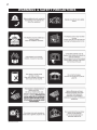
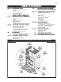
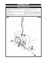
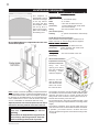
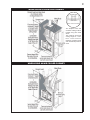
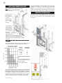
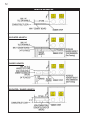
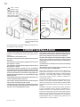
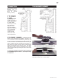
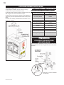
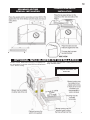
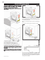
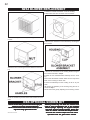
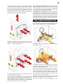
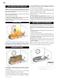
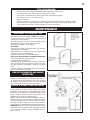
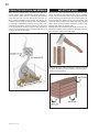
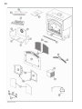
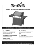
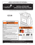
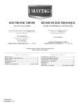
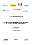
1
W415-0442 / C / 09.01.03
W415-0594 / A / 02.15.07
2
WARNINGS & SAFETY PRECAUTIONS
W415-0594 / A / 02.15.07
3
TABLE of CONTENTS
PG 2-6 INTRODUCTION
7
7-14
14-18
18
19-21
Warnings and safety precautions
Warranty
General Instructions
General Information
Care of Glass & Plated Parts
22
23-27
HI-EFFICIENCY HEATING
INSTALLATION / FRAMING
Location & Clearance
Framing
Outside Combustion Air
Mantel Clearance
Hearth Extension
Faceplate, Uppergrill, Keystone & Door
27-28
CHIMNEY INSTALLATION
Adding Chimney Sections
Offset Chimney Installation
Installing Flashing And Storm Collar
Connection to a Masonry Chimney
Air Cooled Chimney Installation
FINISHING
Attaching the Handle and Air Control Knob
Top Firebrick and Baffle Installation
BLOWER INSTALLATION
29-30
31
32
BLOWER REPLACEMENT
NSK OPTIONAL SCREEN KIT
OPERATING INSTRUCTIONS
Operating sounds & Smells
Starting a Fire
Draft Control
Fuel Loading and Burn Cycle
Re-loading the fireplace
Flash Fires
Overnight Burn
Ash Removal
MAINTENANCE
Run-Away or Chimney Fire
Fire Extinguishers and Smoke Detectors
Door Glass / Gasket Replacement
Creosote Formation And Removal
Selecting Wood
REPLACEMENTS
Replacement Parts
Accessories
TROUBLE SHOOTING
RATING PLATE LOCATION
NZ64 Blower Installation
NZ 150-KT Kit
PLEASE RETAIN THIS MANUAL FOR FUTURE REFERENCE
NOTE: CHANGES, OTHER THAN EDITORIAL, ARE DENOTED BY A VERTICAL LINE IN THE MARGIN.
W415-0594 / A / 02.15.07
4
NAPOLEON products are manufactured under the strict Standard of the World Recognized
ISO 9001 : 2000 Quality Assurance Certificate.
NAPOLEON products are designed with superior components and materials, assembled by trained craftsmen who
take great pride in their work. The complete fireplace is thoroughly inspected by a qualified technician before
packaging to ensure that you, the customer, receives the quality product that you expect from NAPOLEON.
NAPOLEON WOOD FIREPLACE PRESIDENT'S LIFETIME LIMITED WARRANTY
The following materials and workmanship in your new NAPOLEON wood fireplace are
warranted against defects for as long as you own the fireplace. This covers: combustion chamber, heat exchanger, stainless steel baffle retainer, ceramic glass (thermal breakage only), gold
plated parts against tarnishing, porcelainized enamelled components, aluminum extrusion trims
ashdrawer, and cast iron castings.
Electrical (110V) components and wearable parts such as blowers, thermal switch, switches,
wiring, firebrick and gasketing are covered and NAPOLEON will provide replacement parts
free of charge during the first year of the limited warranty.
Labour related to warranty repair is covered free of charge during the first year. Repair
work, however, requires the prior approval of an authorized company official. Labour costs to
the account of NAPOLEON are based on a predetermined rate schedule and any repair work
must be done through an authorized NAPOLEON dealer.
CONDITIONS AND LIMITATIONS
NAPOLEON warrants its products against manufacturing defects to the original purchaser only -- i.e., the individual or legal entity (registered customer) whose name appears on the warranty
registration card filed with NAPOLEON -- provided that the purchase was made through an authorized NAPOLEON dealer and is subject to the following conditions and limitations:
This factory warranty is non-transferable and may not be extended whatsoever by any of our representatives.
The wood fireplace must be installed by an authorized service technician or contractor. Installation must be done in accordance with the installation instructions included with the product
and all local and national building and fire codes.
This limited warranty does not cover damages caused by misuse, lack of maintenance, accident, alterations, abuse or neglect and parts installed from other manufacturers will nullify this
warranty.
This limited warranty further does not cover any scratches, dents, corrosion or discolouring caused by excessive heat, abrasive and chemical cleaners nor chipping on porcelain enamel
parts, nor any venting components used in the installation of the fireplace.
In the first year only, this warranty extends to the repair or replacement of warranted parts which are defective in material or workmanship provided that the product has been operated in
accordance with the operation instructions and under normal conditions.
After the first year, with respect to the President's Limited Lifetime Warranty, NAPOLEON may, at its discretion, fully discharge all obligations with respect to this warranty by refunding to
the original warranted purchaser the wholesale price of any warranted but defective part(s).
After the first year, NAPOLEON will not be responsible for installation, labour or any other costs or expenses related to the reinstallation of a warranted part, and such expenses are not
covered by this warranty.
Notwithstanding any provisions contained in the President's Limited Lifetime Warranty, NAPOLEON’S responsibility under this warranty is defined as above and it shall not in any event extend
to any incidental, consequential or indirect damages.
This warranty defines the obligations and liability of NAPOLEON with respect to the NAPOLEON wood fireplace and any other warranties expressed or implied with respect to this product,
its components or accessories are excluded.
NAPOLEON neither assumes, nor authorizes any third party to assume, on its behalf, any other liabilities with respect to the sale of this product. NAPOLEON will not be responsible for:
over-firing, downdrafts, spillage caused by environmental conditions such as rooftops, buildings, nearby trees, hills, mountains, inadequate vents or ventilation, excessive venting configurations, insufficient makeup air, or negative air pressures which may or may not be caused by mechanical systems such as exhaust fans, furnaces, clothes dryers, etc.
Any damages to fireplace, combustion chamber, heat exchanger, brass trim or other component due to water, weather damage, long periods of dampness, condensation, damaging
chemicals or cleaners will not be the responsibility of NAPOLEON.
The bill of sale or copy will be required together with a serial number and a model number when making any warranty claims from your authorized dealer. The warranty registration card
must be returned within fourteen days to register the warranty.
NAPOLEON reserves the right to have its representative inspect any product or part thereof prior to honouring any warranty claim.
ALL SPECIFICATIONS AND DESIGNS ARE SUBJECT TO CHANGE WITHOUT PRIOR NOTICE DUE TO ON-GOING PRODUCT IMPROVEMENTS. NAPOLEON® IS A
REGISTERED TRADEMARK OF WOLF STEEL LTD. PATENTS U.S. 5.303.693.801 - CAN. 2.073.411, 2.082.915. © WOLF STEEL LTD.
W415-0594 / A / 02.15.07
5
INTRODUCTION
GENERAL INSTRUCTIONS
1. Combustion and dilution air is brought into the unit
through the fresh air intake collars located on the top
rear of the unit.
4. A single air control regulates the burn rate.
2. The combustion air is brought into the firebox through
many small holes in the airwash located at the top and
sides of the opening.
6. The optional blower can be installed to draw fresh
outside air into the home (not recommended in colder
climates), then either the NZ150-KT kit or the NZ64 blower
can be installed inside and will circulate the air into your
home.
3. The dilution air is introduced high in the firebox above
the baffle to cool the chimney.
5. Inside the firebox combustion takes place and exhausts out the chimney.
W415-0594 / A / 02.15.07
6
GENERAL INFORMATION
FEATURES
• Maximum log length of 32"
• Large firebox capacity - 4.8 cu ft.
• Long burn time - up to 14 hours.
• Large glass doors for maximum visibility
• Firebrick lining for firebox protection
• Optional 320 CFM blower for convection heat
• Thermostat for automatic control of the blower
• Outside air for combustion
HEATING SPECIFICATIONS
Approximate Heating Capacity up to 3,000 square feet
(Will vary with the home's floor plan, insulation and outside
temperature.)
Maximum burning time up to 14 hours
BTU Output per hour 10,000 to 80,000
(Cord wood method)
ELECTRICAL SPECIFICATIONS
The blower on "HIGH" draws 2.2 amps on 120 volts A.C.
(approximately 250 watts).
PACKING LIST
Shipped with the fireplace:
Installation manual
Baffle
Ember strip
Log retainer
Flex duct w/ start collar 10' length, 6" dia (1 for NZ150-KT or
blower kit and 2 for outside combustion air supplies).
Shipped with faceplate:
faceplate
12 faceplate screws
Shipped with the door(s):
Installation instuctions and hardware
EPA COMPLIANCE
This heater has been certified epa exempt.
W415-0594 / A / 02.15.07
CALIFORNIA PROP 65 WARNING:
Use of this product may produce smoke which
contains chemicals known to the State of California to cause cancer, birth defects, or other reproductive harm.
Do not use makeshift compromises during
installation. Do not block or restrict air, grille or louvre openings! Do not add a hood.
Burning your unit with door open or ajar creates a
fire hazard that may result in a house and/or chimney
fire.
All venting connections must be in compliance with
the chimney manufacturers installation instructions.
Clearances referred to throughout this manual are
the minimum requirements.
Your Napoleon fireplace must be installed in accordance with all national and local building code standards and the standard of Chimney and Fireplaces,
Vents and Solid Fuel Burning Appliances NFPA #211.
Consult the authority having jurisdiction (such as
municipal building department, fire department, fire
prevention bureau, etc.) to determine the need to
obtain a permit. If you are in doubt about the proper
installation for your situation, contact your dealer or
local building or fire official. The manufacturer does
not guarantee that this fireplace and its options will
completely heat your entire home.
Expansion / contraction noises during heating up
and cooling down cycles are normal and to be expected.
It is recommended that in all cases, the fireplace
be secured to the floor. Use the pallet packing brackets to accomplish this.
CARE OF GLASS, AND PLATED PARTS
If the glass is not kept clean permanent discolouration and /
or blemishes may result. Normally a hot fire will clean the
glass. The most common reasons for dirty glass include: not
using sufficient fuel to get the stove thoroughly hot, using
green or wet wood, closing the draft so far that there is insufficient air for complete combustion. If it is necessary to clean
the glass, use a soft cloth with a non-abrasive cleaner.
Do not clean the glass when hot!
The glass is very strong but do not let burning fuel rest or fall
against it and always close the door gently. Never force it
shut!
If the glass should ever crack while the fire is burning, do not
open the door until the fire is out and do not operate the stove
again until the glass has been replaced with a new 5mm
thick piece of ceramic glass, available from your Napoleon /
Wolf Steel Ltd. dealer. Do not substitute materials.
For information on glass removal and replacement, see
Maintenance.
Do not use abrasive cleaners to clean plated parts. Buff lightly
with a clean dry cloth.
7
HI-EFFICIENCY HEATING
A HOT AIR GRAVITY VENT SYSTEM (NZ221) may be
used to distribute heat to an adjoining room (located either
above, or beside the room containing the fireplace) by way of
vents. Air flow through this vent must be experimented with
and the dampers of the grill adjusted manually to suit your
requirements. This may take a few attempts; thereafter adjustments should no longer be required as is normally experienced with your central heating system registers.
The hot air vent must be installed in an upward direction!
NEVER install in a downward direction. The hot air gravity
vent system is not to be connected to a central heating
system.
No more than two hot air gravity vents may be connected to
the fireplace. Individual vent runs are not to exceed 10 feet.
All hot air gravity vents must be insulated.
INSTALLATION / FRAMING
49 1/2"
24"
51 1/2"
6 5/8"
43"
50 1/4"
10 3/4"
6 1/2"
30 3/4"
8"
29 / "
27 1/2"
12
WARNING:
WARNING:
COMBUSTION AIR
ONLY
BLOWER
CONNECTION ONLY
AVERTISSEMENT:
AIR COMBURANT
SEULEMENT
AVERTISSEMENT:
CONNEXION DE LA
SOUFFLERIE
SEULEMENT
15"
24 3/4"
4 3/8"
19 3/8"
25 3/16"
41"
48 5/8"
30 3/4"
87"
50"
61 1/2"
1
2
"
50 / "
61 3"
12
30 3/4"
50"
61 1/2"
21"
MIN
When framing in unit,
allow ffor
or ffinishing
inishing ma
terial thic
kness
material
thickness
kness..
2 layers
of 1/2" cement
board needed to fill gap A.
W415-0594 / A / 02.15.07
8
LOCATION AND CLEARANCES
The fireplace is
shipped with a set-up
face that is 1/8" larger
on the top, bottom
and each side than
the faceplate. Leave
the set-up face in
place to act as a template when installing
the finishing face.
Do not build shelves or cupboards into the area
above the fireplace.
MAINT
AIN THESE MINIMUM CLEARANCES T
O
MAINTAIN
TO
COMBUSTIBLES:
Framed enclosure
Rear
- 0" to stand-offs (rear)
Sides
- 6" to sides*
Ceiling
- 120" from the base of the unit
(enclosure)
(unless shielded with metal studs
and cement board).
Ceiling
- 84" from the base of the unit
(in front of fireplace)
Chimney
- 2" (follow manufacturers instructions)
- 1"
Hot Air Gravity Ductwork Insulation
This enclosure must provide greater clearance if air
intake vents are run vertical along side the fireplace.
SOLID P
A CK CHIMNEY
PA
Ceiling
- 120" from the base of the unit
(enclosure)
(unless shielded with metal studs
and cement board).
AIR COOLED
Ceiling
- 84" from the base of the unit
(enclosure)
We recommend that the
fireplace be secured to
the floor in all cases.
Using
the
door
opening as a datum,
level the fireplaceby
shimming
underneath the fireplace.
Remove and discard the lifting handles. Bend the tabs
down and secure
the unit to the floor.
Note: In order to avoid the possibility of exposed insulation
or vapour barrier coming in contact with the fireplace body, it
is recommended that the walls of the fireplace enclosure
be “finished” (ie: drywall/sheetrock), as you would finish any
other outside wall of a home. This will ensure that clearance to combustibles is maintained within the cavity.
Objects placed in front of the fireplace must be kept a
minimum of 48" away from the front face of the unit.
IMPORTANT
This unit, fully dressed, weighs 850 lbs
(385.6kg)
Ensure there is adequate floor support for the
unit, chimney and facing material. Some material could weigh thousands of pounds.
W415-0594 / A / 02.15.07
The fireplace enclosure must be provided with sufficient
air circulation to avoid a fire hazard. Install ventilation grilles
(minimum openings of 40 sq. inches) at both floor and
ceiling levels of the enclosure. These grilles must not restrict the flow of heat by more than 25%.
Do not install into any area having a height less than 7 feet
(ceiling of enclosure to fireplace bottom, excluding hearth
height).
The location of windows, doors and the traffic flow in the
room where the stove is to be located should be considered.
If possible, you should choose a location where the
chimney will pass through the house without cutting a floor
or roof joist.
9
WHEN USING A SOLID PACK CHIMNEY
The fireplace face and
enclosure ceiling must be
framed using 2x4 metal
studs.
The minimum enclosure
ceiling height is 7 feet.
Non-combustible
materials (cement board
and metal studs) must be
used.
WHEN USING AN AIR COOLED CHIMNEY
W415-0594 / A / 02.15.07
10
OUTSIDE COMBUSTION AIR
The duct terminations must be located so they can not be
blocked (i.e. snowdrifts). 4' above grade is recommended.
Make a 6 ½" inch hole to suit in an outside wall of the
house. From outside, place the fresh air hood into the hole,
open side down. Seal with caulking and secure.
Note: Incorporate a vertical loop or trap
into air liners to reduce air flow when
unit is not in use.
MANTLE CLEARANCES
An optional combustible mantle must be a minimum of
12" above the top of the faceplate and not to extend more
than 2" from the surface. See chart below for further
information.
Insulating the intake liners is
recommended
in colder
climates to prevent condensation
from
occuring.
The Napoleon
Model NZ6000
takes outside
air directly into
the fireplace
through
the
openings in the left and
right hand sides.
Decide on the most convenient location for the fresh air inlet ducts and
hoods which may be installed above or below
floor level.
The fresh air inlet ducts and hoods must be
installed.
Secure and seal the intake liners to the collars using 3
sheet metal screws, and high temperature sealant.
Vertical
rise is
between:
Horizontal
run may be:
6' & 10' max
3' & 6'
1' & 3'
0' & 1'
5'
15'
20'
25'
Included with the fireplace
are:
- two 10' lengths of vent. Use
a connector and seal if adding more length.
- two of intake hoods.
The vertical height of the air intake liner must not be
greater than 2/3 the height of the chimney. If additional
liner length is required, it may be doubled by increasing
the size from 6" diameter to 8" diameter. Use a 6" to 8"
increaser at the hood and a decreaser at the fireplace.
Values in brackets represent 8" diameter intake liners.
W415-0594 / A / 02.15.07
11
HEARTH EXTENSION
An acceptable 61½" x 20" non-combustible (ie: brick, stone
or ceramic tile) hearth extension must be installed.
Hearth must extend 20" in front of the faceplate when it is
not elevated (see local building codes).
Hearth must extend a minimum of 6" to both sides of the
unit (61 ½").
Hearth must be a minimum of 1" thick cement board (or
equivalent) plus ¼" ceramic tile.
Ensure that the gap
between
the
fireplace and a
combustible hearth
extension is sealed
with sand/cement
grout or covered
with a metal strip (or
both) to prevent
sparks and embers
from falling into this
area.
Elevated hearths must be constructed of noncombustible materials such as cement blocks
or bric
k s.
brick
While the fireplace can be installed directly on the floor, a
non-combustible hearth extension is required in front of
the fireplace, that must not be built higher than the bottom
of the fireplace faceplate. It may therefore be advisable to
build the fireplace on a raised platform.
Hearths raised minimum 6 ½" must extend a minimum of
18".
See hearth
examples.
W415-0594 / A / 02.15.07
12
HEARTH EXAMPLES
ELEVATED HEARTH
RAISED HEARTH
ELEVATED / RAISED HEARTH
W415-0594 / A / 02.15.07
13
FACE PLATE, UPPER GRILL, KEYSTONE & DOOR INSTALLATION
1
4
Remove the
facing template held
in place with the 12
screws shown. Discard the screws and
template.
Right Door Handle
(operating)
- Insert the door rod through the
round hole of the latch ensuring
the flat edge of the “D” shaped
hole points towards the
hinges.
- Slide the end of the door
rod through the bushing at
the top of the door as
shown.
- Insert the handle shaft
through the door and the
latch.
-Secure with 2 flat washers and a nut.
See Note #1
- Feed the handle through
the handle spacer and into
t h e
handle
shaft.
2 Mount the keystone
and upper grill to the faceplate, as shown, using the
4 nuts supplied.
Left Door Handle
(fixed)
Remove the backing and place logo onto the bottom
left corner of the faceplate.
Ensure that the pressure switch actuating arm and air
control rod, protrude through the faceplate when installed.
Remember to record your serial # in the manual for
future quick reference.
3
Secure
the
faceplate to the
unit, using the 12
screws supplied.
Start all 12 screws,
then tighten evenly.
- Insert the handle shaft
through the door.
- Secure with a lock
washer, 2 flat washers
and a nut.
- Feed the handle through
the handle spacer and
into the handle shaft.
See Note #2
Note #1: You may need to move washers to the other side
of the latch to obtain sufficient door seal.
Note #2: The final angle of the left door handle should
mirror the right door handle in the closed position. Tighten
the nut to secure the left handle at the desired angle.
W415-0594 / A / 02.15.07
14
Place brass
washers onto
the faceplate hinge
bushing (2 extra
washers are supplied in order to level
the doors if needed).
5
6
Install the air
c o n t r o l
threaded rod
and knob.
Slide the door hinge pin
into the faceplate hinge
bushing.
To remove the doors, open them slightly and lift them out of
the faceplate hinge bushings.
CHIMNEY INSTALLATION
A raised hearth together with the fireplace built on a raised
platform is recommended for easier wood loading and fire
viewing.
The diameter of the chimney is 8".
A chimney venting the fireplace shall not vent any other
appliance.
The minimum overall chimney height from the top of
the fireplace is 15 feet.
The maximum overall chimney height from the top of
the fireplace is 34 feet.
Factory-built chimney systems for use in dwellings
constructed for three or more families must be enclosed
above the room in which the fireplace is located. This
enclosure must have a fire resistance rating equal to or
greater than that of the floor or roof assembly through
which they pass.
If the chimney system is enclosed within the attic area,
a rafter radiation shield is required.
The chimney should not be built with an offset angle in
excess of 45° in Canada and 30° in USA.
The chimney must extend at least 3 feet above its point
of contact with the roof and at least 2 feet higher than
any wall, roof or building within 10 feet.
W415-0594 / A / 02.15.07
If the chimney extends more than 5 feet above the roof,
it must be secured using a roof brace or guide wires.
Ensure that minimum clearances are maintained.
Portions of the chimney that extend through accessible
spaces must always be encased to avoid personal
contact with the chimney and thereby avoid damage to
the chimney.
A raincap must be installed to avoid internal damage
and corrosion.
The chimney must be supported at a maximum of 20
foot intervals (approx. 200 lbs/20 ft).
This fireplace was tested to CAN /ULC S610 Standard for
Factory Built Fireplaces, and to UL 127 Factory Built
Fireplaces. This Factory Built Fireplace is certified to burn
Fire Wood. The Factory Built Fireplace model: NZ6000
has met test criteria for Zero Clearance Installation to
Combustible Surfaces.
Any 8" diameter chimney listed to these standards may be
installed. In accordance with these standards, the unit may
also be connected to any chimney listed to CAN/ULC-S604
and CAN/ULC-S629 for Canada or UL-103HT for the United
States.
Installation of all types of factory-built chimney systems is
to be in accordance with the chimney manufacturers installation instructions. An appropriate chimney manufacturers anchor base plate and anchor base plate gasket is
required in order to initiate their system. Use the high temperature gasket, supplied, to seal between the anchor plate
and the fireplace top. Air cooled chimney systems are not
recommended in colder climates.
15
STRAIGHT UP
No Off-Set. Minimum overall chimney height is 15 feet.
2 ELBOWS
4 ELBOWS
Single off-set with two 15°, 30° or
45° elbows. Minimum overall
chimney height is 15 feet.
Double off-set with four 15°, 30° or
45° elbows. Minimum overall chimney height is 15 feet.
* The first flue offset closest to the top of the
unit must be a minimum distance of 12 inches
from the top of the fireplace.
1. Move the fireplace into position. Try to center the exhaust flue of the fireplace, midpoint between two joists to
prevent having to cut them. Use a plumb bob to line up the
centre.
2. Cut and frame an opening in the ceiling to provide a
minimum clearance of 2" between the outside of the chimney and any combustible material. DO NOT FILL THIS
SPACE WITH ANY TYPE OF MATERIAL! Nail headers
between the joists for extra support. Firestop spacers must
be placed on each framed opening in any floor or ceiling
that the chimney passes through.
3. Hold a plumb bob from the underside of the roof to
determine where the opening in the roof should be. Cut
and frame the roof opening maintaining proper 2" clearances.
NOTE: 30° or 45° offsets may be installed back to
back.
ADDING CHIMNEY SECTIONS
Add chimney sections, securely, to the required height. Use
a rafter radiation shield whenever the chimney system is
enclosed within an attic area.
- Chimney must extend 3' above the roof.
- Chimney must extend 2' above any portion of the roof
within 10' of the chimney.
W415-0594 / A / 02.15.07
16
OFFSET CHIMNEY INSTALLATION
The first flue offset closest to the top of the unit
must be a minimum distance of 12" from the top
of the fireplace.
Attach an elbow to the chimney section, angled toward the
offset. Secure with 3 - #8X1/2" sheet metal screws. To
achieve the minimum offset, attach and secure a second
elbow. To achieve longer offsets, you may install any
available length of chimney pipe between the elbows to a
maximum length of 4'.
Supports must be used on the first vertical chimney section after a return elbow.
W415-0594 / A / 02.15.07
INSTALLING FLASHING AND STORM
COLLAR
Remove the nails from the shingles above and to the sides
of the chimney. Place the flashing over the chimney pipe
and slide underneath the sides and upper edge of the
shingles. Ensure that the chimney pipe is properly centered
within the flashing, giving a 3/4" margin all around. Fasten
to the roof on the top and sides. DO NOT NAIL through the
lower portion of the flashing. Make weather-tight by sealing with caulking. Where possible, cover the sides and top
edges of the flashing with roofing material. Apply waterproof caulking, provided with the flashing, around the chimney, 1" above the top of the flashing and push the storm
collar down into the caulking. Insert a rain cap onto the top
of the last chimney section.
17
CONNECTION
TO A MASONRY CHIMNEY
The Napoleon Model
NZ6000
may
be
connected to either a
lined
or
unlined
masonry chimney.
IF THE CHIMNEY
IS LINED, the flues
must be made of
vitrified clay and be in
sizes of 8" square or
8" round (inside
diameters) or 8"x12"
with a minimum
height of 15 feet
above the fireplace.
Eight inch round flues
are recommended.
Installation must
conform to both
national and local
code requirements.
IF THE CHIMNEY IS UNLINED,
a stainless steel liner
listed to either Standard ULC-S640M in Canada or UL1777 in the USA: Liners for New Masonry Chimneys, may
be used to connect the fireplace to the chimney. The liner
must be continuous from the fireplace to the chimney cap
and be installed only per manufacturers instructions. In
both cases, the chimney structure must be supported by
angle iron anchored into the masonry walls. The allowable masonry used in chimney construction is 3-1/2" brick,
solidly mortared and fully encasing the flue. Ensure there
are no leaks.
In no case is the masonry enclosure to be supported
by the NZ6000 fireplace. Allow a 1" (one inch) air cavity
for expansion.
ANCHOR PLATE
HI-TEMP GASKET
FIREPLACE TOP
FLUE TILE SUPPORT FOR A MASONRY FIREPLACE
FIREPLACE TOP
For a masonry fireplace use a flue tile support. For a prefabricated chimney use an anchor plate.
W415-0594 / A / 02.15.07
18
AIR COOLED CHIMNEY INSTALLATION
1. Remove the knock out.
2. Cut away the insulation to gain access to the ring.
3. Remove the ring secured by four screws.
4. Slide the starter collar through the insulation wrap and
affix using the four screws removed in step 3.
5. Secure the inner liner of the chimney to the fireplace 8"
collar using 3 screws supplied with the starter collar (W1700098).
6. Follow the chimney manufacturer's instructions for installing the chimney.
AIR COOLED CHIMNEY REQUIREMENTS
Use only the ffollowing
ollowing br
himne
y.
brand
chimne
himney
and and type of c
Chimney Components
FMI 8DM
12" Chimney Section
12-8DM
18" Chimney Section
18-8DM
24" Chimney Section
24-8DM
36" Chimney Section
36-8DM
48" Chimney Section
48-8DM
Offsets
30E-8DM
Flashing
6F 8 or 12F 8
Chimney Cap
RTL-8HT
Roof Support
38 RS
Firestop
FS-8DM
Chimney Components
Wolf Steel
Starter Collar
NZAC-KT
FINISHING
ATTACHING THE HANDLE AND
AIR CONTOL KNOB
The door latch is adjusted by moving the washer from one
side of the latch to the other. Tighten the outer nut to secure
the latch.
Install the air control threaded
rod and knob.
W415-0594 / A / 02.15.07
19
SECONDARY AIR TUBE
REMOVAL / INSTALLATION
FIREBRICK AND BAFFLE
INSTALLATION
OPTIONAL NZ64 BLOWER KIT INSTALLATION
Route a 120 Volt, 60Hz electrical supply (not supplied) from
the electrical box on the side of the unit to the electrical box
on the blower housing.
The unit comes complete with a safety switch and a thermally activated switch.
For complete instructions, see
blower kit.
W415-0594 / A / 02.15.07
20
NZ64 BLOWER INSTALLATION
This unit is supplied with a pressure switch and
a thermally activated switch. Ensure that the
pressure switch actuating arm protrudes
through the faceplate when installed.
The blower will only operate when the doors are
fully closed.
3. Connect the 6” collar to the blower opening located
on the side of the unit. An optional opening is covered on
the other side of the unit. If this location is preferred, switch
the cover plate and collar.
Secure by reaching through the collar and bending the
tabs.
Use sealant to ensure that the connection is air tight.
1. Remove the template.
2. Position the blower to an inside or outside wall into a framed opening 12 3/8” wide by 10 1/2” high. (Outside wall
not recommended in colder climates as cold air may
be drawn into the house when the fireplace is off.)
The blower housing should be installed onto a
level surface large enough to support the blower
assembly
y..
Allow for finishing material when securing the
blower housing, as the grill mounts to the housing.
We recommend installing the blower in a different room or
even different level of the house. This will generate greater
air movement and improve the distribution of the warm air
coming from the fireplace.
W415-0594 / A / 02.15.07
21
4. Electrical Connection
a) Remove the junction box covers on the unit and the
blower.
5. Connect the 6” liner to the unit and blower collars. Secure using 3 screws on each end and seal with caulking.
Liner supplied stretches to a maximum of 10’.
b) Removing the junction box cover on the unit exposes 4
black, labeled wires:
Two wires labelled "by-pass" - go to by-pass (summer)
switch (not supplied - overides the thermally activated
switch enabling the user to run the blower without heat).
Important:
Marrett by-pass (summer) switch wire leads separately (do not connect together), if the by-pass
switch is not desired.
One wire labelled "blower" - connects to KB-35 rheostat
(not supplied) and then KB-35 blower wire connects to
white blower wire.
One wire labelled "L1" - connects to power (hot lead).
c) Removing the junction box cover on the blower exposes
3 coloured wires:
One black wire - connects to power "L2" (neutral lead).
One green wire - connects to ground.
One white wire - connects to KB-35 rheostat (not supplied)
See above.
6. Insert the filter into the grill. Foam gasket (1/2” weather
stripping) between the grill and blower housing is recommended, but not supplied.
The blower filter is washable.
7. The bottom lip of the grill latches over the bottom lip of
the housing. Use two screws to secure the top of the grill to
the facing.
NZ150-KT KIT
The circulation air inlet pipe must terminate outside of the
fireplace enclosure to ensure proper air flow around the
firebox.
The 6" circulation air inlet pipe may be connected to either
the NZ64 blower kit or the NZ150-KT kit.
Avoid terminating higher than the bottom of the doors on
the unit to prevent air flow reversal.
An optional opening is
covered on the other side of the unit. If this location is preferred, switch the cover plate andW415-0594
collar. / A / 02.15.07
22
NZ64 BLOWER REPLACEMENT
4. Slide the bracket and blower out of the housing.
5. Disconnect the wire connector from the blower.
1. Remove the grill and filter by removing the 2 securing
screws.
6. Remove the old blower from the bracket by removing the
four screws.
2. Remove the nut securing the blower bracket to the housing.
7. Secure the new blower to the existing bracket using the
four screws removed in step 6.
8. Slide the new blower/bracket assembly into the housing.
Ensure that the blower bracket slides into the clips at the
back of the housing on either side.
9. Push the assembly into the housing as far in as possible.
10. Secure the assembly to the housing using the nut removed in step 2.
11. Re-secure the grill by replacing the 2 securing screws.
3. Lift the handles to pull the blower and bracket off of the
stud.
NSK OPTIONAL SCREEN KIT
Use the screen when you are in the room to enjoy the
ambience of an open, w
ac
kling ffir
ir
wood
crac
ack
ire
ood cr
e.
Medium sized wood loads should be used to prevent
logs from rolling against the screen.
W415-0594 / A / 02.15.07
Chimney action may not allow the screen to be
used in some installations due to the resulting
smok
smoke
spillag
by-pass
e spilla
g e. Opening the b
y-pass damper
ma
y help pr
e v ent smok
e spilla
ge. W
ood will
may
pre
smoke
spillag
Wood
burn at a faster rate and heat output will be
less with the screen compared to the stove
operation with the glass doors closed.
23
OPERATING INSTRUCTIONS
Expansion / contraction noises during heating up and cooling down cycles are normal and to be be expected.
OPERATING SOUNDS AND SMELLS
A slight humming sound may be heard depending on the
location of the blower. This sound may be minimized by
turning down the blower.
When first installed, the fireplace and the steel are cold
and must become hot before the fireplace will function
well. During the break-in period (the first 2 or 3 fires) create
only small, hot fires using kindling; this will allow the firebrick to cure. Do not be alarmed if small hairline cracks
develop in the firebrick. This is a normal occurrence and
does not pose a safety hazard. The paint may also smell a
little for the first few fires as it cures and you may wish to
open a door or window to alleviate the smell.
There are many different ways to start a fire, review the
hints and warnings in this section to ensure the fire is
started properly.
STARTING A FIRE
Make sure the air control is on high (far right position). You
may also open the doors 1" to 2" during the first five minutes
of start-up, if additional air is needed.
Opening the by-pass damper will help heat up the chimney
more quickly. If desired close after draft is established.
Never use gasoline, gasoline-type lantern fuel, kerosene,
charcoal lighter fluid, or similar liquids to start or freshenup a fire in this fireplace. Keep all such liquids well away
from the fireplace while it is in use.
If using a firestarter, use only products specifically designed
for fireplaces - follow the manufacturer's instructions
carefully.
Use plenty of newspaper and kindling to ensure the
fireplace reaches a proper temperature. Once the kindling
is burning rapidly, place a few larger pieces of wood onto
the fire.
Tip: When first lighting a fire, if the smoke is not quickly
drawn into the chimney, there may be a downdraft or cold
air in the chimney.
Roll up some newspaper, light it and place it near the fireplace flue until the chimney begins to draw. When a fire is
burning, open the door slowly to avoid drawing smoke into
the room.
A properly installed Napoleon fireplace should not smoke.
If yours does, check the following: Has the chimney had
time to get hot? Are the air intake hoods blocked closed? Is
the smoke passage blocked anywhere in the fireplace or
chimney? Is the smoke flow impeded by too long a
horizontal pipe or too many bends? Is it a weak draft perhaps caused by a leaky chimney, a cold outside chimney,
too short a chimney, or a chimney too close to trees or a
higher roof?
DRAFT CONTROL
Draft is the force which moves air from the fireplace up
through the chimney. The amount of draft in your chimney
depends on the length of the chimney, local geography,
nearby obstructions and other forces. Adjusting the draft
control regulates the temperature. The draft can be adjusted from a low burn rate with the air control on the low
setting to a fast burn rate with the air control on the high
setting (far right position).
Inadequate draft may cause back-puffing into the room
and may cause plugging of the chimney. Too much draft
may cause an excessive temperature in the fireplace, glowing red fireplace parts or an uncontrollable burn which can
all lead to a chimney fire or a permanent damage to the
unit.
Remove all source of gasoline or other flammable vapours and liquids in the vicinity of this or
other appliances prior to lighting.
1. To start, a brisk fire is required. Place loosely crumpled
paper on the floor of the fireplace behind the log retainer.
W415-0594 / A / 02.15.07
24
2. Cover with dry kindling.
5. To maintain a brisk fire, a hot coal bed must be established and maintained.
3.Open the draft control fully by moving the lever to the right
(HIGH setting).
6. Slowly add larger wood (2x4 size pieces). Lay the pieces
lengthwise from side to side in the hot coal bed with a
shallow trench between, so that the primary air can flow
directly into this trench and ignite the fuel above.
7. When the fire seems to be at its peak, medium sized
logs may be added. Once these logs have caught fire,
carefully close the door.
Closing the door too quickly after refueling will reduce
the firebox temperature and may result in an
unsatisfactory burn.
4. Light the paper and leave the door slightly ajar (one to
two inches) until all kindling is burning.
W415-0594 / A / 02.15.07
25
As soon as the door is closed, you will observe a change
in the flame pattern. The flames will get smaller and lazier
because less oxygen is getting into the combustion chamber. The flames, however, are more efficient. The flames
will remain lazy but become larger again as soon as the
firebricks have been heated thoroughly and the chimney
becomes heated and provides a good draft.
Can't get the fireplace operating? Use more kindling and
paper. Assuming the chimney and vent are sized correctly
and there is sufficient combustion air, the lack of sufficiently
dry quantities of small kindling is the problem. Thumb size
is a good gauge for small kindling diameter.
Can't get heat out of the fireplace? One of two things may
have happened. The fireplace door may have been closed
prematurely and the fireplace itself has not reached optimum temperature. Re-open the door and/or draft control to
re-establish a brisk fire. The other problem may have been
wet wood. The typical symptom is sizzling wood and moisture being driven from the wood.
FUEL LOADING AND BURN CYCLE
The bricks will be nearly all white and the glass mostly
clear. The whiteness of the bricks and the cleanness of the
glass are good indicators of your operating efficiency.
At this point, the roaring fire that you see when the door is
opened is wastefully drawing heated room air up the
chimney -- certainly not desirable.
So always operate with the door fully closed once the medium sized logs have caught fire.
You can now add larger pieces of wood and operate the
fireplace normally. Once the fireplace is entirely hot, it will
burn very efficiently with little smoke from the chimney. There
will be a bed of hot coals in the firebox so you can safely fill
the firebox with wood to the top of the andirons.
Not enough heat is produced when only one or two pieces
of wood are burned.
A minimum of three pieces are needed to encase a bed of
coals that sustains the fire. Loosely stacked wood burns
quicker than a tightly packed load.
Wood burns in cycles rather than giving a steady output of
heat. It is best to plan these cycles around your household
routine so that only enough coals are left to start the next
load. In the evening, load your fireplace, at least, a halfhour before bed to ensure the fire is hot enough to close
the draft control for an overnight burn.
Burn only dry seasoned wood. It produces more heat and
less soot or creosote. Do not burn ocean beach wood. Its
salt content can produce a metal eating acid.
W415-0594 / A / 02.15.07
26
RE-LOADING THE FIREPLACE
When refueling open the door slowly to prevent smoke
spillage. Use a pair of long fireplace gloves when feeding
the fire. Keep a small steel shovel nearby to use as a
poker and to remove ashes. Do not store wood within 4
feet (1m) of the fireplace.
Follow the directions below to minimize smoke spillage
while re-loading the fireplace.
1. Move the air control to high.
2. Open the door slightly. Allow the airflow inside the firebox
to stabilize before opening the doors fully.
3. Load wood to the top of the cast retainers and burn at a
medium low setting.
FLASH FIRES
A flash fire is a small fire burned quickly when you don't
need much heat. After your kindling has "caught", load at
least 3 pieces of wood, stacked loosely. Burn with the draft
control fully open or closed only slightly.
OVERNIGHT BURN
This fireplace is large enough to accomodate overnight,
14 hour burns. Follow these steps below to achieve an
overnight burn.
1. Get the fireplace hot by moving the air control to high
and letting the fireplace burn for 15 minutes.
2. Load your larger pieces of wood compactly, packed close
enough to prevent the flames from penetrating it completely.
W415-0594 / A / 02.15.07
3. After approximately 30 minutes, depending on the size of
the load, close the draft control completely making sure
that the fire is not extinguished.
4.In the morning the fireplace should still be hot, with
embers in the coal bed. Stir the coals and load small pieces
of wood to re-ignite the fire, if desired.
Note: Differences in chimney height and draft may lower
overall burn times.
DO NOT OVERFIRE THE FIREPLACE! Overfiring can occur
by: a) burning large amounts of smaller wood pieces. b)
vigorously burning large loads of wood with the draft control
on "HIGH" (fully open) for long periods of time (one or two
hours).
ASH REMOVAL PROCEDURES
A bed of ashes approximately 1 inch deep should be left on
the firebox bottom to help maintain a hot charcoal bed.
When the fire has burned down and cooled, remove any
excess ashes. To remove the ash, follow the directions
below.
1. After the last coal has extinguished, let the fireplace cool
at least two hours.
2. Open the fireplace doors.
3. Scoop the ash from the firebox into a metal, airtight, container with a lid. Cover the container with the lid and move
the container away from the fireplace to ensure the ashes
cool. Dispose of the ashes.
Warning: Improper disposal of ashes result in fires. Do
not discard ashes in cardboard boxes, dump in back yards,
or store in garages.
Note: If using a vacuum to clean up ashes, be sure the
ashes are entirely cooled. Using a vacuum to clean up
warm ashes could cause a fire inside the vacuum.
27
TIPS FOR BURNING
•
•
•
•
•
•
Create a large fire to heat up the fireplace before adjusting to a slower burn.
To create a large, quick burning fire, use small pieces of wood.
For a lower, but extended burn, stack larger pieces of wood close together.
For long burns, leave a 1-2" bed of ashes.
Burn dry wood only.
With the exception of overnight burns, create large, quick burning fires whenever possible. Smaller,
slow burning fires, using large logs, cause the glass to become dirty. Larger, quick burning fires
using medium sized wood to refuel frequently are much more efficient.
MAINTENANCE
RUN-AWAY OR CHIMNEY FIRE
Run-away fires can be the result of FOUR major factors:
1. Using incorrect fuel, or small fuel pieces which would
normally be used as kindling.
2. Leaving the door ajar too long and creating extreme
temperatures as the air rushes in the open door.
3. Improperly installed or worn gaskets.
SOLUTIONS:
1. Do not burn treated or processed wood, coal, charcoal,
coloured paper or cardboard.
2. Be careful not to overfire the unit by leaving the door
open too long after the initial start-up.
3. Replace worn, dried out (inflexible) gaskets.
WHAT TO DO IF A RUN-AWAY OR CHIMNEY FIRE STARTS:
1. Close the draft fully (lowest position).
2. Call the local fire department.
3. Examine the chimney, attic and roof of the house, to see
if any part has become hot enough to catch fire. If necessary spray with a fire extinguisher or water from a garden
hose.
4. Do not operate the stove again until you are certain the
chimney has not been damaged.
FIRE EXTINGUISHERS AND SMOKE
DETECTORS
All homes with a solid fuel burning fireplace should have
at least one fire extinguisher in a central location, known to
all, and at least one smoke detector in the room containing
the fireplace. If it sounds an alarm, correct the cause but
do not de-activate or relocate the smoke detector.
GLASS & GASKET REPLACEMENT
At the end of each burning season inspect the door gasket
ensuring that it is not worn or loose. Replace with proper
fibreglass rope. The purpose of door gasketing is to seal
the firebox. If the doors are not sealed, air leaks into the
firebox, creating a quick burning fire. This situation is not
desireable for overnight or extended burns.
Replace cracked or broken glass immediately. When reinstalling the glass, be sure that the glass and gasket
create a solid seal around door frame. Follow the instructions below for glass removal. You many require a flat tool
to gently press the gasket between the glass and the door.
WARNING: Make sure that the glass and gasket are fully
installed down into the glass retainer. If the glass protrudes
too far out of the retainer, the glass will shatter when the
door is closed.
W415-0594 / A / 02.15.07
28
CREOSOTE FORMATION AND REMOVAL
SELECTING WOOD
When wood is burned slowly, it produces tar and other
organic vapours which combine with expelled moisture to
form creosote. These vapours condense in the relatively
cooler chimney flue of a slow burning fire and when ignited, make an extremely hot fire. Check your chimney for
creosote and soot build-up monthly until a safe frequency
for cleaning is established (minimum once a year). If accumulation is excessive, clean the chimney. You may want
to call a professional chimney sweep to clean it. Both the
chimney and the fireplace have to be cleaned at least once
a year or as often as necessary.
Burn only dry, clean unpainted wood that has been seasoned. It produces more heat and less soot or creosote.
Freshly cut wood contains about 50% moisture while after
proper seasoning only about 20% of the water remains. As
wood is burned, this water boils off consuming energy that
should be used in heating. The wetter the wood, the less
heat is given off and the more creosote is produced. Dry
firewood has cracks in the end grain.
Both hardwood and softwood burn equally well in this fireplace but hardwood, which is denser, will weigh more per
cord and burn a little slower and longer.
Firewood should be split and stacked in a manner that air
can get to all parts of it and covered in early spring to be
ready for burning that fall.
W415-0594 / A / 02.15.07
29
REPLACEMENTS
Contact your dealer for questions concerning prices and
policies on replacement parts. Normally all parts can be
ordered through your Napoleon dealer or distributor.
When ordering replacement parts always give the following information:
1.
2.
3.
4.
5.
FOR WARRANTY REPL
ACEMENT PAR
TS, A PHO
TOCOPY OF
REPLA
ARTS
PHOT
THE ORIGINAL INVOICE WILL BE REQUIRED TO HONOUR THE
CLAIM.
FIREPLACE AND ACCESSORY
REPLACEMENT PARTS
#
PART NO. DESCRIPTION
1
2*
3*
4*
5*
6
7
8
9
10
11
12
13*
14*
15
16
17*
18*
19
20
21
22
23*
24*
25*
26*
W300-0069
W562-0035
W562-0036
W010-1225
W690-0005
W090-0099
W090-0101
W090-0100
W090-0098
W090-0097
W010-1399
W062-0018
KB35
W690-0002
W010-1184
W010-1183
W200-0141
W555-0047
W380-0017
W010-1193
W010-1180
W325-0029
W175-0002
NZ220-2
W410-0005
W010-0067
27
28
29*
30
31
32
33*
W715-0628
W185-0020
W385-0245
W410-0026
W010-1594
W290-0121
W450-0028
DOOR GLASS
DOOR OR GLASS GASKET
DOOR GASKET - CENTRE
GLASS & GASKET
120V THERMOSTAT
REAR FIREBRICK
BOTTOM RIGHT FIREBRICK
BOTTOM LEFT FIREBRICK
RIGHT SIDE FIREBRICK
LEFT SIDE FIREBRICK
BAFFLE
BLOWER - NZ64
VARIABLE SPEED CONTROL INCL KNOB
HEAT SENSOR
LEFT DOOR ASSEMBLY
RIGHT DOOR ASSEMBLY
PRIMARY AIR PLATE
PRIMARY AIR ROD
PRIMARY AIR KNOB
PRIMARY AIR ACCESS COVER
ASH LIP ASSEMBLY
DOOR HANDLE - BIRD CAGE
8" COUPLER
5'X8" DIA. AIR VENT (FOR GRAVITY HOT AIR VENT)
10'X8" DIA AIR VENT (FOR CENTRAL HEATING SYSTEM)
VENT SUPPORT BRACKET (FOR CENTRAL HEATING
SYSTEM )
ANDIRONS
GRATE
NAPOLEON LOGO
10'X6" AIR SUPPLY VENT
SECONDARY AIR TUBE
GASKET, SECONDARY AIR TUBE
NUT, HEX BRASS
MODEL & SERIAL NUMBER OF FIREPLACE
INSTALLATION DATE OF FIREPLACE
PART NUMBER
DESCRIPTION OF PART
FINISH
* IDENTIFIES ITEMS WHICH ARE NOT ILLUSTRATED.
FOR FURTHER INFORMATION, CONTACT YOUR
NAPOLEON DEALER.
ACCESSORIES
#
PART NO. DESCRIPTION
34
34
34
34
35
35
35
36
36
36
37
37
37
38
39
40*
41
42
12*
31*
32
33*
H335-K
H335-G
H335-SC
H335-WI
FPK
FPSC
FPWI
UGK
UGG
UGSC
KSK
KSG
KSSC
NSK
CP
NZ221
NM228-M
NZAC-KT
NZ64
W250-0005
W305-0007
NZ150-KT
ARCHED DOORS - BLACK
ARCHED DOUBLE DOORS - GOLD PLATED
ARCHED DOUBLE DOORS - SATIN CHROME FINISH
ARCHED DOUBLE DOORS - WROUGHT IRON FINISH
FACEPLATE ARCHED - BLACK
FACEPLATE ARCHED - SATIN CHROME FINISH
FACEPLATE ARCHED - WROUGHT IRON FINISH
UPPER GRILL ARCHED - BLACK
UPPER GRILL ARCHED - GOLD PLATED
UPPER GRILL ARCHED - SATIN CHROME FINISH
KEYSTONE - BLACK
KEYSTONE - GOLD PLATED
KEYSTONE - SATIN CHROME FINISH
ARCHED DOUBLE SCREEN KIT WITH STAND
CRANE AND POT
GRAVITY HOT AIR VENT KIT
FLUE TILE SUPPORT
AIR COOLED CHIMNEY KIT
BLOWER KIT
BLOWER FILTER
BLOWER GRILL
CIRCULATION AIR MOUNTING KIT
W415-0594 / A / 02.15.07
30
W415-0594 / A / 02.15.07
31
TROUBLE SHOOTING GUIDE
BEFORE
ATTEMPTING TO TROUBLESHOOT, PURGE YOUR UNIT AND INITIALLY LIGHT THE PILOT AND THE MAIN BURNER WITH THE GLASS DOOR OPEN.
SYMPTOM
PROBLEM
TEST SOLUTION
Smoke enters the Cold air blockage.
room during startClose the doors.
up.
- burn a piece of newspaper to establish a draft.
Kindling does not Cold air blockage.
start - fire smolders.
Not enough starter paper.
- burn a piece of newspaper to establish a draft.
Not enough air.
- if the flame is not getting enough air, first make sure the air control
is open. If additional air is needed, open the doors a small crack
only.
- open the by-pass damper
- use additional newspaper if necessary.
- first make sure the air control is fully open. If additional air is
needed, a small crack in the doors is all that is needed.
Smoke enters the Insufficient Draft.
room while reloading.
- Chimney height and outside conditions can negatively affect draft.
In these cases a small amount of smoke may enter the home. Adding more pipe or a draft-inducing cap may help.
Fireplace does Wood is wet.
not burn hot
Insufficient Draft.
enough.
- see the section on "Selecting Wood" for details.
Air control is not wide open.
The by-pass damper is in the
"open" position
Blower does not Fireplace is not up to
run.
temperature.
Faceplate is cold.
- Chimney height and outside conditions can negatively affect draft.
In these cases a small amount of smoke may enter the home. Adding more pipe or a draft-inducing cap may help.
- make sure the air control is open all the way. Slide the control back
and forth rapidly to insure the control is not stuck.
- close the by-pass damper
- this is normal. The blower will come on when the fireplace is hot usually 15 to 30 minutes.
Electricity is cut to the blower.
- check the household breaker or fuse to make sure it is operable.
This is normal.
- the air leading into the firebox comes from the exterior. In some
cases this air comes into the firebox and exits up the chimney. This
will not damage the fireplace.
Fireplace does The doors are not sealing.
- the doors are not sealing - see the section "Door Glass / Gasket
not burn overnight.
Replacement" for details.
The by-pass damper is in the - close the by-pass damper
"open" position
W415-0594 / A / 02.15.07
RATING PLATE IS LOCATED BEHIND THE FIREPLACE FACEPLATE.
32
RATING PLATE
W415-0594 / A / 02.15.07