1
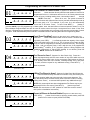
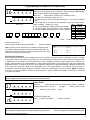
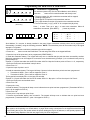
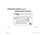
INSTALLATION
INSTRUCTIONS
R
GEM-RP3DGTL
Digital Keypad
This Guide includes programming instructions for the
following control panels: • GEM-P816
• GEM-P1632
• GEM-P3200
• GEM-P9600
Quick Start:
GEMINI
1. Referring to the control panel wiring diagram, connect siren, aux. power, pgm.
output, remote bus, earth ground, zone and telephone wiring.
NOTE: See Installation Instructions for the appropriate control panel.
17
A
2. Connect AC power first and then the battery.
3. Configure the keypad (see page 3).
E
RM
D ST
ATU
SYSTEM ARMED
01/01/97 12:00AM
ENT
INTERIOR
BYPASS
FIRE/TBL
SYS TBL
A1
CHIME
S
NEXT/YES
A
1
2
3
B
4
5
6
C
7
8
9
D
0
E
PRIOR/NO
F
AREA
G
COMPUTERIZED SECURITY SYSTEM
4. Access the Easy Menu Driven (Dealer Program) Mode:
Press 456789 A
Dealer Code
R
For the GEM-P3200 and
GEM-P9600, use the
Master Security Code
printed on the control panel
microprocessor shield.
GEM-RP3DGTL Keypad
Press NO(F) Until “17” appears on the keypad display.
Press YES (E) To Enter Easy Menu Driven Dealer Program Mode.
The Easy Menu Driven Program Mode will allow you to complete all basic programming
functions by answering questions which will allow the automatic programming of the
control panel.
F For the GEM-P816 and GEM-P1632, turn to page 5
F For the GEM-P3200 and GEM-P9600, turn to page 10
This guide is to be used in conjunction with the Programming Instruction Manual for the
respective control panel.
GEM-P816 - WI995
GEM-P1632 GEM-P3200 GEM-P9600 -
© Napco 1999
WI897
WI818
WI777
WI982A 6/99
2
INTRODUCTION
The GEM-RP3DGTL is a dual 7-segment digital keypad that is compatible with the NAPCO GEM-Series GEM-P816,
P1632, P3200 & P9600 control-panels. Refer to User Guide OI249 for operation instructions. While the GEM-RP3DGTL
may be used to fully program the control, the GEM-RP1CAe2 keypad provides the optimum in ease of keypad
programming.
SPECIFICATIONS
Operating Voltage: 12 V DC (supplied by panel)
Current Drain:50 mA Standby
Dimensions: 4 3/8” x 5 7/8” x 11/16”
Note: Subtract keypad current from combined auxiliary current of the control panel.
MOUNTING THE KEYPAD
A keypad should be located near each exit/entry door. To open the case, insert a screwdriver into either slot at the bottom
and push up with a slight twisting motion to release the retainer tab. Repeat for the other slot. Pull out at the bottom and lift
off the two hooks at the top.
The GEM-RP3DGTL features a handy pull-up reference label. (This label must be used in UL installations.) Before
mounting the keypad onto the wall, push the Sliding Label Plate (with label and felt backing affixed and handle facing
forward) down the guides at the rear of the keypad until it snaps into place. Once installed, the Sliding Label Plate cannot
be removed without first removing the keypad from the wall. Note: The keypad fire and panic keys should not be
considered a substitute for a listed manual initiating device, such as a pull box.
If installing onto a double-gang box, insert mounting screws through the two vertical elongated holes on the left side of the
case and into the box. If the box is visible when viewed from the front, adjust the keypad vertically and tighten the screws.
Then, using hardware suitable for the mounting surface, add one or two screws at the right side of the keypad case directly
into the wall to ensure a secure installation. Note: Do not over tighten the screws! Uneven walls may cause the keypad
case to distort.
WIRING
Connect the keypad wires to the control panel
terminals shown in the table at the right.
Caution: Do not run keypad wiring with loop wiring.
KEYPAD CONFIGURATION
COLOR
RED
BLACK
GREEN
YELLOW
WHITE
WHITE
TERMINAL
9
10
11
12
N/O PANIC
N/O PANIC
* Cut and insulate 2 white wires if not used.
Up to 7 GEM-RP3DGTL keypads may be connected to
the control panel (Keypads 1–7). Each must be configured for a keypad address. In addition,
the keypad may be configured to disable touchpad backlight and entry sounder. Keypads are configured by the proper
selection of jumpers. Refer to the label on the keypad circuit board for jumper locations and a summary of settings.
KEYPAD ADDRESS
If more than one keypad is installed:
• Each must be assigned a unique address (that is, no two keypads may be numbered alike).
• Keypads must be addressed consecutively (that is, missing numbers are not permitted).
• Only Keypad No. 1 may be used for programming. (However, for ease of programming, it is recommended that a GEM-RP1CA/
RP1CAe/RP1CAe2 be selected as Keypad #1.)
• Assign the keypad address number by selecting Jumpers J1–3 in accordance with the table below.
*Note: (1) Keypads are factory supplied with no jumpers installed and a as such are automatically configured as Keypad No. 1. (2) Only one keypad in the system may be configured as Keypad No. 1, otherwise none will function.
TOUCHPAD BACK LIGHT
Cut Jumper A to disable touch pad back lighting.
DISABLE SOUNDER
Cut Jumper C to disable the sounder. (Do not disable in UL applications.)
ENABLE KEYPAD TAMPER
Cut Jumper D to enable Keypad Tamper.
ENABLE TAMPER LED
Cut Jumper E to covert the Keypad CHIME LED to a SYSTEM TAMPER
LED. (Only on control panels which support system tamper)
KEYPAD
NUMBER
1
1
OFF or
ON
2
•
3
ON
4
•
5
ON
6
•
7
ON
JUMPER SETTINGS
2
3
PARK
•
•
ON
ON
•
•
ON
ON
ON
ON
ON
ON
STORE SPARE
JUMPERS
IN THIS
POSITION
For Sales and Repairs, call toll free: (800) 645-9445
For direct line to Technical Service, call toll free: (800) 645-9440
Internet: http://www.napcosecurity.com
3
EASY PROGRAM MODE OVERVIEW
ENTERING THE EASY KEYPAD PROGRAM MODE
1 Enter the Dealer Security Code (default = 456789) for a new panel or enter your custom Dealer Program Code if
programmed and press A
2 Press NO (F) repeatedly until function “17“ (Activate Program Mode) is displayed.
NOTE: If you pass “17“ you can scroll back by pressing B .
3 Press YES (E) to enter the Dealer Program Mode.
Use the following guide to answer the Easy Program Mode questions which will quickly allow you to create a custom
default program. Press A to set cursor, NEXT (E) to go forwards, PRIOR (F) to go backwards, J to save
and C twice to exit the Easy Program Mode .
ANSWERING A QUESTION IN THE EASY PROGRAM MODE
The Easy Program Mode the questions will be in the form of a 2 digit number flashing in the digital display.
Pressing A will set the cursor into the next field to answer the question.
Using this book as a guide, enter the appropriate data in response to each question and then press J to save.
If no additional programming is necessary for the question, press NEXT (E) to go to the next question.
REVIEWING THE DATA ENTRY IN THE EASY PROGRAM MODE
The data entered in response to an Easy Program Mode question may be reviewed before saving.
• After entering the data before pressingJ to save, A may be pressed until the 2 digit question number appears
flashing in the display again.
•
Pressing A will step through all the fields of the question for review and will then result in the 2 digit question
number flashing in the display again.
If the data is correct, pressJ to save.
If the data is not correct, press A to set the cursor into the next field and again enter the appropriate data.
Note: The contents of an Easy Program Mode question may be reviewed after the initial programming of the control, with
the exception of the questions which are marked (Appears for New Panel Only). These questions set up the basic
structure of the control panel program (Number of zones in an area, etc.) and cannot be viewed or altered once set.
EXITING THE DEALER PROGRAM MODE
If in the Easy Program Mode, press C to enter the Direct Address Program Mode. Press the C button once again
to end all programming and resume normal keypad operation.
RESETTING THE CONTROL PANEL TO FACTORY DEFAULT
If necessary, the control panel can be returned to the factory default and be re-programmed from scratch.
• For the GEM-P816 and GEM-P1632, enter the address program mode, go to location 1198 and press J
( A1198J )
•
For the GEM-P3200 and GEM-P9600, enter the address program mode, go to location 4093 and press J
( A4093J )
4
Programming the GEM-P816 & GEM-P1632
01
Total Number of Zones in Area 1 (Appears for New Panel Only)
INTERIOR
BYPASS
FIRE/TBL
SYS TBL
CHIME
INTERIOR
BYPASS
FIRE/TBL
SYS TBL
CHIME
(Direct Entry)
Press the A button and then directly enter the total number of zones to be
programmed for Area 1. Valid entries are from 01 to 32. Directly enter the total
number of zones, including leading zeros. Use number buttons 1 through
9. NOTE: Press the 0 button for a zero. The system is based on
groups of 4 zones each (after the first 8 zones), and will automatically round up
to the next group of 4. For example, if you enter 18, it will automatically
convert this to 20 zones. Press Jto save. Press NEXT (E) button to
proceed. NOTE: If you are programming a 2 Area system, enter the total number of zones required for Areas 1 & 2. The
Direct Address Program Mode can then be used to remove zones from Area 1 and place them in Area 2. See Zone
Options. If Programming a Wireless Only system, or using wireless only on Zones 9-32, enter the total number of zones
in system. Enter the transmitter points in the RF Transmitter section of the Easy Menu Driven Programming Mode.
Panel Zone Doubling?(Appears for New Panel Only)
03
INTERIOR
BYPASS
FIRE/TBL
SYS TBL
CHIME
INTERIOR
BYPASS
FIRE/TBL
SYS TBL
CHIME
(Press YES or NO)
(GEM-P1632 only)
Press the A button. If the total number of zones in Area 1 entered was 16
or greater, press YES (E) to effectively double the capacity of the control
panel's hard wired zones from 8 to 16. The 16 zones will no longer be EOL
zones, but will be designated for Normally Closed devices only. The terminal
for Zone 1 will now support Zones 1 and 9 with the use of the supplied EZ
Zone DoublingTM resistors, E & Z supplied. (Refer to Wiring Diagram and
Installation Instructions). If Panel Zone doubling is not desired, press NO
(E). NOTE: Answer NO for GEM-P816
Fire Zones in Area 1 (Appears for New Panel Only) Press the
04
INTERIOR
BYPASS
FIRE/TBL
SYS TBL
CHIME
INTERIOR
BYPASS
FIRE/TBL
SYS TBL
CHIME
A
button and then directly enter the zone number of any zones which are to be
used as Fire Zones (both 2-wire, 4-wire or wireless). Valid entries are from 01
to 32. Directly enter each zone number, including leading zeros, and press
Jto save, and then repeat for any additional zone(s). Press NEXT (E)
button to proceed.
(Press YES or NO)
2-Wire Fire Zones in Area 1 (Appears for New Panel Only) Press the
05
A
INTERIOR
BYPASS
FIRE/TBL
SYS TBL
CHIME
INTERIOR
BYPASS
FIRE/TBL
SYS TBL
CHIME
(Press YES or NO)
06
GEMINI
ARME
A
1
2
3
B
4
5
6
C
7
8
9
D
0
NOTE: Only zones which have been designated as Fire Zones may be programmed as 2 Wire Fire zones. Press NEXT (E) button to proceed.
NOTE: JP3 must be set to “2-WF” position for 2-wire fire zones for zones 7
and 8 (refer to Installation Instructions).
Report all Zones to Central Station?(Appears for New Panel Only)
SYSTEM ARMED
01/01/97 12:00AM
ENT A1
TUS
D STA
button and then directly enter the zone number of any Fire Zones (from
previous question) which are to be used with 2-wire smoke detectors. The
only valid entries are 07 and 08. Directly enter each zone number, including
leading zeros. Press Jto save and then repeat for any additional zone(s).
INTERIOR
BYPASS
FIRE/TBL
SYS TBL
CHIME
BYPASS
FIRE/TBL
SYS TBL
CHIME
Press YES (E) button for all zones to report to central station; press NO
(F) button for no zones to report (LOCAL SYSTEM).
NEXT/YES
E
PRIOR/NO
F
AREA
G
COMPUTERIZED SECURITY SYSTEM
R
INTERIOR
(Yes or No)
5
Programming the GEM-P816 & GEM-P1632
07
Entry/Exit Zones in Area 1 (Appears for New Panel Only)
INTERIOR
BYPASS
FIRE/TBL
SYS TBL
CHIME
Press the A button and then directly enter the zone number of any zones
which are to be used as Entry/Exit zones. Valid entries are from 01 to 32. Directly enter each zone number, including leading zeros.
Use number buttons 0 through 9.
INTERIOR
BYPASS
FIRE/TBL
SYS TBL
CHIME
Press Jto save and then repeat for any additional zone(s). Press NEXT (E)
button to proceed. NOTE: Chime will automatically be programmed for all E/E zones.
(Direct Entry)
08
Interior Zones in Area 1 (Appears for New Panel Only)
INTERIOR
BYPASS
FIRE/TBL
SYS TBL
CHIME
INTERIOR
BYPASS
FIRE/TBL
SYS TBL
CHIME
(Direct Entry)
09
Press the A button and then directly enter the zone number of any zones
which are to be used as Interior Zones. Valid entries are from 01 to 32. Directly enter each zone number, including leading zeros. Use number buttons
0 through 9. Press Jto save and then repeat for any additional
zone(s). Press NEXT (E) button to proceed. NOTE: All Interior zones will
also be automatically programmed as “Exit/Entry Follower” zones.
Number of Keypads in Area 1
INTERIOR
BYPASS
FIRE/TBL
SYS TBL
CHIME
Press the A button and then directly enter the total number of Keypads to
be installed in Area 1. Valid entries are from 01 to 07. Directly enter the
number of keypads, including leading zeros. Use number buttons 0
through 9. Press
INTERIOR
BYPASS
FIRE/TBL
SYS TBL
CHIME
(Direct Entry)
11
NOTE: Area 2 keypads can only be assigned in Direct Address Programming.
See Keypad Options.
Central Station Receiver 1 Telephone Number
INTERIOR
BYPASS
FIRE/TBL
SYS TBL
CHIME
INTERIOR
BYPASS
FIRE/TBL
SYS TBL
CHIME
(Direct Entry)
12
Jto save . Press NEXT (E) button to proceed.
Press the A button and using the number buttons, directly enter telephone
number of up to 16 digits including prefix, if necessary, for receiver 1.
Central Station Receiver 1 Telephone Number
NOTE: Central Station Receiver 2 and 3 Telephone Numbers can be entered
in Direct Address Programming. See CS Reporting Options.
Press Jto save . Press NEXT (E) button to proceed.
Central Station Receiver 1 Account Number
INTERIOR
BYPASS
FIRE/TBL
SYS TBL
CHIME
INTERIOR
BYPASS
FIRE/TBL
SYS TBL
CHIME
Press the A button and then directly enter an account number of up to
four digits.
Central Station Account #
(Direct Entry)
NOTE: Central Station Receiver 2 and 3 Account Numbers can be entered in
Direct Address Programming. See CS Reporting Options.
For Central Station Telephone and Account Numbers: Use number buttons 1 through 9 for digits 1–9; press
G0 for a zero and G 1 through G 5 for letters B–F, respectively. NOTE: Pre-Dial Delay = “D”;
Dial-Tone Detection = “E”. Pressing the 0 button will produce a blank space (•).
6
13
Programming the GEM-P816 & GEM-P1632
Central Station Receiver 1 Format
INTERIOR
BYPASS
FIRE/TBL
SYS TBL
CHIME
From the table below, enter the central station's receiver format. Use number
buttons 1 through 9. NOTE: Press G0 for a zero and 0
for a blank space (•). Press G 1 through G 4 for letters B–E,
respectively. Press Jto save. Press NEXT (E) button to proceed.
INTERIOR
BYPASS
FIRE/TBL
SYS TBL
CHIME
(Direct Entry)
14
DATA
ENTRY
CS RECEIVER 1 FORMAT
DATA
ENTRY
CS RECEIVER 1 FORMAT
•(blank)
2
Ademco Slow, Silent Knight Slow
5
Universal High Speed
Radionics Fast
B
SIA
3
Silent Knight Fast
C
Ademco Point ID
4
Radionics, CD, Franklin Slow
E
Pager
Enter User Codes
INTERIOR
INTERIOR
BYPASS
BYPASS
FIRE/TBL
FIRE/TBL
SYS TBL
CHIME
SYS TBL
CHIME
User #
User Code
DATA ENTRIES
For default program, enter up to 32 User Codes, with Area 1 and Area 2
Options.Press the (A) button once to set the cursor to the User Code.
Use the number buttons 0 through 9 to enter the User Number,
followed by a User Code of up to 6 digits. Enter G0 for a blank.
NOTE: If “Enable Global Ambush Code”(Address 0720) is enabled and
“Global Ambush Code” (Address 1054) is left blank(•), do not program the first
two digits of ANY User Code as '99'.
(Direct Entry)
•
NOTE: Central Station Receiver 2 and 3 Formats can only be entered in
Direct Address Programming. See CS Receiver Options.
Area 1
Options
Area2
Options
NOTE: When entering the Area 1 and
Area 2 options, press G0 for a
ten. Enter 0 for a blank.
USER AREA OPTIONS - Select the desired Area Options (Area 1 and Area 2) from the table below.
OPTION ENABLED
L
blank(•)
blank(•)
R
Disabled
EXPLANATION
blank(•)
1
Arm/Disarm
blank(•)
2
Arm Only
blank(•)
3
Service
A Service Code has restricted arm/disarm rights; if an area is armed with a Service Code, the area can be disarmed
with any valid User Code, including a Service Code. If the area is armed with OTHER than a Service Code, it CANNOT
be disarmed with a Service Code.
blank(•)
4
Access
blank(•)
Add 8
* User Program
This is normally used to activate a door striker while an area is disarmed. Also program “Access Control on PGM2
Output” (Address 0719) and “PGM2 Output Access Control Timeout” (Address 0711).
User Program Option is enabled for Keypad 1 only, wherever it is connected (Area 1 or Area 2).
User Code not active in this area.
Allows User Code to arm/disarm this area.
Prevents User Code from disarming this area.
Press Jto save. To proceed to the next User Code, press the A button to set the cursor to the User Number and
change it using the number buttons.
•
If the programmed code was less than 6 digits, enter blanks G0 for the remaining digits.
Example: Program a code of “2222” for user 02, with area 1 options of “Arm/Disarm” and “User Program”:
Enter 02 for the user number, 2222 G0 G0 for a user code,
G09 “(blank) 9” for area 1 options and G0G0 “(blank) (blank)” for area 2 options.
CHANGING OR CANCELING A CODE: To change any code, merely program over the existing code as described above
and press Jto save. Similarly, to cancel a code, blank out each number of the code press Jto save.
7
Programming the GEM-P816 & GEM-P1632
15
RF Transmitter Programming
INTERIOR
INTERIOR
BYPASS
BYPASS
FIRE/TBL
FIRE/TBL
SYS TBL
SYS TBL
(Direct Entry)
CHIME
CHIME
(For wireless systems only. Also see Quick Method, which follows)
Press the A button and for each transmitter (key fob transmitters also),
then directly enter:
1 The zone number (01–32) to which the transmitter will be mapped,
including leading zeros.
2 The 6-digit RF ID # printed on the transmitter and box.
3 The 1-digit checksum number (C) printed on the transmitter and box.
4 The Point number (1–4) (P); enter “9” for unsupervised (all points).
Press
Jto save. Then go to step 1 to enter next transmitter. When all
transmitters are entered, press NEXT (E) button to proceed.
Zone #
6-digit RF ID #
Checksum # Point #
NOTE: When programming the RF ID number:
“A” = G 0 ; “B” = G 1 ;
“C” = G 2 ; “D” = G 3 ;
“E” = G 4 ; “F” = G 5 .
Quick Method. If a receiver is already installed in the panel, Napco transmitter wireless points can be programmed
automatically (“enrolled”) using the following procedure. NOTE: The transmitter point will be enrolled only if the signal
strength is 3 or greater.
1. Enter the zone number to which the transmitter point will be mapped.
2. Press the B button to enter the Enroll Mode. The red and green LEDs on the keypad will flash.
3. Open the loop of the point that is to be programmed (GEM-TRANS2 only).
4. Install the transmitter battery. The keypad will beep once to indicate that the point has been successfully enrolled.
Multi-point transmitters can be mapped to successive zones simultaneously (Example 1) or to selected zones point by
point (Example 2).
Example 1. A GEM-TRANS2 transmitter has the RF ID number 410078:1. Map both points to Zones 11–12, respectively.
1. Enter the Enroll mode as described in step 2 above.
2. Enter Zone “11”.
3. Open the loops of points 1 and 2.
4. Install the transmitter battery. The keypad will beep 3 times to indicate that three points have been programmed.
• Transmitter 410078:1, point 1 will be mapped to Zone 11.
• Transmitter 410078:1, point 2 will be mapped to Zone 12.
The keypad will now display Zone 12, the last zone enrolled.
Example 2. A GEM-TRANS2 transmitter has the RF ID number 287613:1. Map point 1 to Zone 6 and point 2 to Zone 9.
1. Enter the Enroll mode as described above.
2. Enter Zone “06”.
3. Open point-1 loop.
4. Install the battery. The keypad will beep once to indicate that one point has been programmed. (Transmitter 287613:1,
point 1 will be mapped to Zone 6.)
5. Enter Zone “09”.
6. Close point-1 loop and open point-2 loop.
7. Remove the transmitter battery, then re-install it. The keypad will beep once to indicate that one point has been
programmed. (Transmitter 287613:1, point 2 is mapped to Zone 9.)
KEY FOB ZONE ASSIGNMENT: Key fobs can also be assigned to zones to allow multiple wireless panic buttons on one
alarm system, each reporting to a central station, or pager while having a description on the keypad that describes the
person holding the key fob, the location where the person holding the key fob is stationed, or the special purpose of the
key fob button being depressed. See the next page on Key fob Zone Assignment.
8
Programming the GEM-P816 & GEM-P1632
16
Key Fob Transmitters
INTERIOR
BYPASS
FIRE/TBL
SYS TBL
CHIME
INTERIOR
BYPASS
FIRE/TBL
SYS TBL
CHIME
(Direct Entry)
Keyfobs can be programmed as “Arm/Disarm” devices using the ON and OFF
buttons (refer to control panel installation instructions).
Press the A button and for each Key Fob Transmitter, enter:
1 The Key Fob Transmitter number (01–15).
2 The area number to which transmitter is assigned (1 or 2); enter 0 to disable
keyfob.
3 The 6-digit RF ID # printed on the transmitter (enter all numbers and/or
letters, including leading “0”s, if any).
DATA
AUX 1/AUX 2
ENTRY
4 The 1-digit checksum number printed on transmitter.
OPTIONS
5 The Aux-1 Option (see key fob Aux 1 & Aux 2 options). •(blank)
None
Keypad Panic
6 The Aux-2 Option (see key fob Aux 1 & Aux 2 options). 9
0
KeyFob #
Area #
6-digit RF ID #
Checksum #
Aux1 #
Aux K.P. Panic
B
Instant
C
Toggle Aux Relay
D
Access Control
Aux2 #
Press
Jto save. Then go to step 1
to enter next Key Fob.
When all Key Fobs are entered, press NEXT (E) button to proceed.
Note: If the Key Fob is converted for Two Button “Emergency Use”
(by cutting an internal jumper), both top or bottom buttons must be
depressed to activate an alarm. In this case, the Key Fob may not be
used to arm or disarm the contrl panel.
NOTE: When programming the ID Code number:
“A” = G 0 ; “B” = G 1 ;
“C” = G 2 ; “D” = G 3 ;
“E” = G 4 ; “F” = G 5 .
Key Fob Zone Assignment
Each of the 4 key fob buttons can be assigned to a zone. For example, On button = point 1; Off button = point 2; A1 = point
3; A2 = point 4. Up to 32 key fobs (using 1 button) or 16 key fobs (using 2 buttons) or 8 key fobs (using all 4 buttons) or any
combination up to a maximum of 32 controlled zones can be assigned, providing multiple wireless panic buttons on a
system, each reporting to the Central Station or a pager and/or annunciating on a keypad the key fob zone number with
description/location. To assign a key fob to a zone: program the keyfob as you would a transmitter, entering the keyfob's ID
code, check sum and point number at the appropriate zone. The “Quick Method” is not allowed. The zone may be
hardwired to a sensor as well as assigned to a key fob (either one will activate the zone alarm output). NOTE: If assigning
a key fob to a zone, the “ON/OFF” buttons on the key fob will no longer arm/disarm the system. The key fob is converted
to a “panic only” device.
ZONE DESCRIPTIONS: GEM-R3DGTL cannot be used to enter Zone Descriptions. To enter Zone Descriptions you must
use the GEM-RP1CAe2 Keypad or the Napco Quickloader Software.
17
rE
Dealer Code
INTERIOR
BYPASS
FIRE/TBL
SYS TBL
CHIME
INTERIOR
BYPASS
FIRE/TBL
SYS TBL
CHIME
Press the A button directly enter the Dealer Code (default = 456789),
including leading zeros. Use the 1 through 9 buttons. NOTE: Press
the 0 button for a zero. Press Jto save.
Re-enter the Dealer Code.
Press Jto save. Press NEXT (E) button to proceed.
INTERIOR
BYPASS
FIRE/TBL
SYS TBL
CHIME
(Direct Entry)
EXIT DEALER PROGRAM MODE: This completes the custom default program. Press the C button to enter the
Direct Address Program Mode for further programming or press the C button once again to end all programming and
resume normal keypad operation.
9
Programming the GEM-P3200 & GEM-P9600
01
Total Number of Zones and Keypads in Area 1.
Total Number of Zones and Keypads in Area 2.
INTERIOR
BYPASS
FIRE/TBL
SYS TBL
CHIME
(Appears for New Panel Only)
2
INTERIOR
BYPASS
FIRE/TBL
SYS TBL
CHIME
(Direct Entry)
Press 3 to
select # of
zones in Area 1
2
Press 3 to
select # of
K/Ps in Area 1
J
2
Press 3 to
select # of
zones in Area 2
Press 3 to
select # of
K/Ps in Area 2
1 Press the A button and then press 3 to select the total number of zones to be programmed for Area 1. Valid
entries are from 08 to 24 in multiples of 4.
2 Press 2 and press 3 to select the total number of keypads to be programmed for Area 1.
If no zones are to programmed for Area 2, pressJ to save followed by NEXT (E) to proceed.
3 If Area 2 is to be programmed, press 2 and then press 3 to select the total number of zones to be
programmed for Area 2.
4 Press 2 and press 3 to select the total number of keypads to be programmed for Area 3.
Note: the first zone of Area 1 (and Area 2, if selected) will automatically be programmed as an Exit/Entry zone with an
entry delay of 30 seconds and an exit delay of 60 seconds. The second zone will be programmed as an Exit/Entry
Follower Zone. In a single-area system, Zone 8 will be programmed as a 2-Wire Fire Zone (set Jumper JP7 to configure
zone 8 for 2 Wire Fire). In a two-area system, zones 7 and 8 will be programmed as 2-Wire Fire Zones and will be
common to both areas (set Jumper JP7 to configure zone 7 and 8 for 2 Wire Fire).
02
Report all Zones to Central Station?(Appears for New Panel Only)
INTERIOR
BYPASS
FIRE/TBL
SYS TBL
CHIME
INTERIOR
BYPASS
FIRE/TBL
SYS TBL
CHIME
Press YES (E) button for all zones to report to central station; press NO
(F) button for no zones to report (LOCAL SYSTEM).
(Yes or No)
03
Central Station Receiver 1 Telephone Number
INTERIOR
BYPASS
FIRE/TBL
SYS TBL
CHIME
INTERIOR
BYPASS
FIRE/TBL
SYS TBL
CHIME
Central Station Receiver 1 Telephone Number
NOTE: Central Station Receiver 2 and 3 Telephone Numbers can be entered
in Direct Address Programming. See CS Reporting Options.
Press Jto save . Press NEXT (E) button to proceed.
(Direct Entry)
04
Press the A button and using the number buttons, directly enter telephone
number of up to 16 digits including prefix, if necessary, for receiver 1.
Central Station Receiver 1 Account Number
INTERIOR
BYPASS
FIRE/TBL
SYS TBL
CHIME
INTERIOR
BYPASS
FIRE/TBL
SYS TBL
CHIME
Press the A button and then directly enter an account number of up to
four digits.
Central Station Account #
(Direct Entry)
NOTE: Central Station Receiver 2 and 3 Account Numbers can be entered in
Direct Address Programming. See CS Reporting Options.
Press Jto save. Press NEXT (E) button to proceed.
For Central Station Telephone and Account Numbers: Use number buttons 1 through 9 for digits 1–9; press
G0 for a zero and G 1 through G 5 for letters B–F, respectively. NOTE: Pre-Dial Delay = “D”;
Dial-Tone Detection = “E”. Pressing the 0 button will produce a blank space (•).
10
Programming the GEM-P3200 & GEM-P9600
05
Central Station Receiver 1 Format
INTERIOR
BYPASS
FIRE/TBL
SYS TBL
CHIME
INTERIOR
BYPASS
FIRE/TBL
SYS TBL
CHIME
From the table below, enter the central station's receiver format. Use number
buttons 1 through 9. NOTE: Press G0 for a zero and 0
for a blank space (•). Press G 1 through G 4 for letters B–E,
respectively. Press Jto save. Press NEXT (E) button to proceed.
NOTE: Central Station Receiver 2 and 3 Formats can only be entered in Direct
Address Programming. See CS Receiver Options.
(Direct Entry)
DATA
ENTRY
CS RECEIVER 1 FORMAT
DATA
ENTRY
CS RECEIVER 1 FORMAT
•(blank)
Ademco Slow, Silent Knight Slow
4
1
Sescoa, Vertex, DCI, Franklin Fast
5
2
Radionics Fast
3
Silent Knight Fast
06
DATA
ENTRY
CS RECEIVER 1 FORMAT
Radionics, DCI, Franklin Slow
0
Radionics Modem 2
Universal High Speed
B
SIA
8
Radionics BFSK
C
Ademco Point ID
9
FBI 4/3/1
D
Ademco Expres
E
Pager
Enter User Codes
INTERIOR
INTERIOR
BYPASS
FIRE/TBL
FIRE/TBL
BYPASS
SYS TBL
SYS TBL
CHIME
For default program, enter up to 8 User Codes for Area 1 (Users 1 - 8) and up
to 8 User Codes for Area 2 (Users 9 - 16) . Press the (A) button once to
set the cursor to the User Number.
When programming User Options, Authority Level and Access Keypads:
“A” = G 0 ; “B” = G 1 ; “C” = G 2 ;
CHIME
“D” = G 3 ; “E” = G 4 ; “F” = G 5 .
(Direct Entry)
1 Enter the User Number to be programmed, including leading zeros. Use the number buttons 0 through 9 .
2 Enter a User Code of up to 6 digits. Use the number buttons 0 through 9 to enter the code followed by
G0 for each blank.
3 Enter the User Options. Refer to the User Option table below.
4 Enter the Authority Level. Refer to the Authority Level table below.
5 If this code is to be used to activate a door strike, assign the User to the appropriate access control keypad from the
Access Control Keypad table below.
User #
User Code
USER OPTIONS
COD E
LEVEL
TYPE
blank (•)
NONE
ARM/DISARM
blank (•)
1
LEVEL 1
ARM/DISARM
1
Y
2
LEVEL 2
ARM/DISARM
2
Y
3
LEVEL 3
ARM/DISARM
3
ENTRIES
VIEW
PROGRAM
blank (•)
DISABLED
Y
Y
Y
6
7
Y
Y
Y
Y
Y
Y
8
9
Y
Y
F
Y
NONE
ARM ONLY
5
LEVEL 1
ARM ONLY
5
6
LEVEL 2
ARM ONLY
6
7
1
Y
2
Y
3
Y
4
Y
5
Y
Y
6
Y
Y
7
Y
Y
K.P. 1
K.P. 2
blank (•)
NONE
Y
Y
DATA
ENTRIES
7
LEVEL 3
ARM ONLY
NONE
SERVICE
8
Y
Y
9
LEVEL 1
SERVICE
9
Y
Y
0
LEVEL 2
SERVICE
0
Y
Y
B
LEVEL 3
SERVICE
B
Y
Y
C
Y
Y
Y
D
Y
Y
Y
E
Y
E
4
4
K.P. 7
Y
C
D
DATA
K.P. 5 K.P. 6
ENTRIES
8
Y
0
B
OVERVIEW
Y
4
5
BYPASS
ACCESS CONTROL KEYPADS
ACCESS CONTROL KEYPADS
AUTHORITY
USER
3
Access Control
DATA
BLOCKED
2
Level
ENTRIES
DATA
1
Option
F
K.P. 3
K.P. 4
NONE
Y
Y
Y
Y
Y
Y
Y
Y
Y
Y
Y
Y
Y
Y
Y
Y
Y
Y
Y
Y
Y
Y
Y
Y
Y
Y
Y
Y
Y
Y
Y
Y
CHANGING OR CANCELING A CODE: To change any code, merely program over the existing code as described above
and press Jto save. Similarly, to cancel a code, blank out each number of the code press Jto save.
11
Programming the GEM-P3200 & GEM-P9600
07
RF Transmitter Programming
INTERIOR
INTERIOR
BYPASS
BYPASS
FIRE/TBL
FIRE/TBL
SYS TBL
SYS TBL
(Direct Entry)
CHIME
CHIME
(For wireless systems only. Also see Quick Method, which follows)
Press the A button and for each transmitter and directly enter:
1 The zone number (01–96) to which the transmitter will be mapped,
including leading zeros.
2 The 6-digit RF ID # printed on the transmitter and box.
3 The 1-digit checksum number (C) printed on the transmitter and box.
4 The Point number (1–4) (P); enter “9” for unsupervised (all points).
Press
Jto save. Then go to step 1 to enter next transmitter. When all
transmitters are entered, press NEXT (E) button to proceed.
Zone #
6-digit RF ID #
Checksum # Point #
NOTE: When programming the ID Code number:
“A” = G 0 ; “B” = G 1 ;
“C” = G 2 ; “D” = G 3 ;
“E” = G 4 ; “F” = G 5 .
Quick Method. If a receiver is already installed in the panel, Napco transmitter wireless points can be programmed
automatically (“enrolled”) using the following procedure. NOTE: The transmitter point will be enrolled only if the signal
strength is 3 or greater.
1. Enter the zone number to which the transmitter point will be mapped.
2. Press the B button to enter the Enroll Mode. The red and green LEDs on the keypad will flash.
3. Open the loop of the point that is to be programmed (GEM-TRANS2 ).
4. Install the transmitter battery. The keypad will beep once to indicate that the point has been successfully enrolled.
Multi-point transmitters can be mapped to successive zones simultaneously (Example 1) or to selected zones point by
point (Example 2).
Example 1. A 4-point transmitter has the RF ID number 410078:1. Map the first three points to Zones 11–12, respectively.
1. Enter the Enroll mode as described in step 2 above.
2. Enter Zone “11”.
3. Open the loops of points 1 and 2.
4. Install the transmitter battery. The keypad will beep 3 times to indicate that three points have been programmed.
• Transmitter 410078:1, point 1 will be mapped to Zone 11.
• Transmitter 410078:1, point 2 will be mapped to Zone 12.
The keypad will now display Zone 12, the last zone enrolled.
Example 2. A 2-point transmitter has the RF ID number 287613:1. Map point 1 to Zone 6 and point 2 to Zone 9.
1. Enter the Enroll mode as described above.
2. Enter Zone “06”.
3. Open point-1 loop.
4. Install the battery. The keypad will beep once to indicate that one point has been programmed. (Transmitter 287613:1,
point 1 will be mapped to Zone 6.)
5. Enter Zone “09”.
6. Close point-1 loop and open point-2 loop.
7. Remove the transmitter battery, then re-install it. The keypad will beep once to indicate that one point has been
programmed. (Transmitter 287613:1, point 2 is mapped to Zone 9.)
KEY FOB ZONE ASSIGNMENT: Key fobs can also be assigned to zones to allow multiple wireless panic buttons on one
alarm system, each reporting to a central station, or pager while having a description on the keypad that describes the
person holding the key fob, the location where the person holding the key fob is stationed, or the special purpose of the
key fob button being depressed. See the next page on Key fob Zone Assignment.
12
Programming the GEM-P3200 & GEM-P9600
08
Key Fob Transmitters
INTERIOR
BYPASS
FIRE/TBL
SYS TBL
CHIME
INTERIOR
BYPASS
FIRE/TBL
SYS TBL
CHIME
(Direct Entry)
Keyfobs can be programmed as “Arm/Disarm” devices using the ON and OFF
buttons (refer to control panel installation instructions).
Press the A button and for each Key Fob Transmitter, enter:
1 The Key Fob Transmitter number (01–15).
2 The area number to which transmitter is assigned (1-8); enter 0 to disable
keyfob.
3 The 6-digit RF ID # printed on the transmitter (enter all numbers and/or
letters, including leading “0”s, if any).
DATA
AUX 1/AUX 2
ENTRY
4 The 1-digit checksum number printed on transmitter.
OPTIONS
5 The Aux-1 Option (see key fob Aux 1 & Aux 2 options). •(blank)
None
Keypad Panic
6 The Aux-2 Option (see key fob Aux 1 & Aux 2 options). 9
0
KeyFob #
Area #
6-digit RF ID #
Checksum #
Aux1 #
Aux K.P. Panic
B
Instant
C
Toggle Aux Relay
D
Access Control
Aux2 #
Press Jto save. Then go to step 1 to enter next Key Fob.
When all Key Fobs are entered, press NEXT (E) button to proceed. NOTE: When programming the ID Code number:
“A” = G 0 ; “B” = G 1 ;
Note: If the Key Fob is converted for Two Button “Emergency Use”
“C”
= G 2 ; “D” = G 3 ;
(by cutting an internal jumper), both top or bottom buttons must be
“E” = G 4 ; “F” = G 5 .
depressed to activate an alarm. In this case, the Key Fob may not be
used to arm or disarm the contrl panel.
Key Fob Zone Assignment (refer to display as shown on the previous page: press the (F) button to go backwards.)
Each of the 4 key fob buttons can be assigned to a zone. For example, On button = point 1; Off button = point 2; A1 = point
3; A2 = point 4. Up to 32 key fobs (using 1 button) or 16 key fobs (using 2 buttons) or 8 key fobs (using all 4 buttons) or any
combination up to a maximum of 32 controlled zones can be assigned, providing multiple wireless panic buttons on a
system, each reporting to the Central Station or a pager and/or annunciating on a keypad the key fob zone number with
description/location. To assign a key fob to a zone: program the keyfob as you would a transmitter, entering the keyfob's ID
code, check sum and point number at the appropriate zone. The “Quick Method” is not allowed. The zone may be
hardwired to a sensor as well as assigned to a key fob (either one will activate the zone alarm output). NOTE: If assigning
a key fob to a zone, the “ON/OFF” buttons on the key fob will no longer arm/disarm the system. The key fob is converted
to a “panic only” device.
ZONE DESCRIPTIONS: GEM-RP3DGTL cannot be used to enter Zone Descriptions. To enter Zone Descriptions you
must use the GEM-RP1CAe2 Keypad or the Napco Quickloader Software.
EXIT DEALER PROGRAM MODE: This completes the custom default program. Press the C button to enter the
Direct Address Program Mode for further programming or press the C button once again to end all programming and
resume normal keypad operation.
13
DIRECT ADDRESS PROGRAM MODE
This is an extension of the Dealer Program Mode. This method of programming is used in conjunction with the Keypad
Programming Worksheets contained in the control panel programming guide. Refer to these worksheets to identify the
4-digit location (address) of the feature to be programmed. An illustrative example is provided on the next page.
KEYPAD PROGRAMMING OVERVIEW
Direct Address Programming allows you to go directly to the address
DATA ENTRY
locations and change the data entries to customize your control panel ADDRESS
LOCATIONS
options. Whereas the Easy Menu Program Mode is a simple quick LOCATIONS
LEFT
DIGIT
RIGHT DIGIT
start guide with limited options, the Direct Address Program Mode is
0000
3
C
more flexible allowing you to change all the options.
It consists of multiple address locations with two data entry locations
each (left and right) as shown in the adjacent diagram.
0000
TO
4095
HEXADECIMAL DATA:
BLANK (•) = No Options
1 to 9 = Entries 1 to 9
0 = Entry of 10
B to F = Entries 11 to 15
ACCESSING DIRECT ADDRESS PROGRAM MODE
17
INTERIOR
INTERIOR
BYPASS
BYPASS
FIRE/TBL
FIRE/TBL
SYS TBL
SYS TBL
(Direct Entry)
CHIME
CHIME
1 Enter the Dealer Security Code (default = 456789) for a new panel or
enter your custom Dealer Program Code if programmed.
2 Press A
3 Press NO (F) repeatedly until function “17“ (Activate Program
Mode) is displayed.
4 Press YES (E) to enter the Dealer Easy Program Mode.
5 Press C to enter the Dealer Address Program Mode.
ENTERING DATA IN THE ADDRESS PROGRAM MODE
1
2
3
4
Press A
Enter the 4 digit Address location
Enter the 2 digit data
Press D to save.
D
A
Address #
Use 0 -9
for digits 0 - 9
EXAMPLE: Program an Alarm Timeout of 30 seconds.
Press A0712 1G4
•
•
14
Alarm Timeout location = 0712
30 second timeout = 1E
D
Data
Use 1 -9 for digits 1 - 9
BLANK= 0
A/10 = G 0
B =
G1
C =
G2
D =
G3
E =
G4
F =
G5
15
NAPCO SECURITY SYSTEMS, INC. (NAPCO) warrants its products to be free from manufacturing defects
in materials and workmanship for thirty-six months following the date of manufacture. NAPCO will, within said
period, at its option, repair or replace any product failing
to operate correctly without charge to the original purchaser or user.
This warranty shall not apply to any equipment, or any
part thereof, which has been repaired by others, improperly installed, improperly used, abused, altered, damaged, subjected to acts of God, or on which any serial
numbers have been altered, defaced or removed. Seller
will not be responsible for any dismantling or reinstallation charges.
THERE ARE NO WARRANTIES, EXPRESS OR IMPLIED, WHICH EXTEND BEYOND THE DESCRIPTION ON THE FACE HEREOF. THERE IS NO EXPRESS OR IMPLIED WARRANTY OF MERCHANTABILITY OR A WARRANTY OF FITNESS FOR
A PARTICULAR PURPOSE. ADDITIONALLY, THIS
WARRANTY IS IN LIEU OF ALL OTHER OBLIGATIONS OR LIABILITIES ON THE PART OF NAPCO.
Any action for breach of warranty, including but not
limited to any implied warranty of merchantability, must
be brought within the six months following the end of the
warranty period.
IN NO CASE SHALL NAPCO BE LIABLE TO ANYONE
FOR ANY CONSEQUENTIAL OR INCIDENTAL DAMAGES FOR BREACH OF THIS OR ANY OTHER WARRANTY, EXPRESS OR IMPLIED, EVEN IF THE LOSS
OR DAMAGE IS CAUSED BY THE SELLER'S OWN
NEGLIGENCE OR FAULT.
In case of defect, contact the security professional who
installed and maintains your security system. In order to
exercise the warranty, the product must be returned by
the security professional, shipping costs prepaid and
insured to NAPCO. After repair or replacement, NAPCO
assumes the cost of returning products under warranty.
NAPCO shall have no obligation under this warranty, or
otherwise, if the product has been repaired by others,
improperly installed, improperly used, abused, altered,
damaged, subjected to accident, nuisance, flood, fire or
acts of God, or on which any serial numbers have been
altered, defaced or removed. NAPCO will not be responsible for any dismantling, reassembly or reinstallation
charges.
thorizes any other person purporting to act on its behalf
to modify, to change, or to assume for it, any other
warranty or liability concerning its products.
In no event shall NAPCO be liable for an amount in
excess of NAPCO's original selling price of the product,
for any loss or damage, whether direct, indirect, incidental, consequential, or otherwise arising out of any failure
of the product. Seller's warranty, as hereinabove set
forth, shall not be enlarged, diminished or affected by
and no obligation or liability shall arise or grow out of
Seller's rendering of technical advice or service in connection with Buyer's order of the goods furnished hereunder.
NAPCO RECOMMENDS THAT THE ENTIRE SYSTEM
BE COMPLETELY TESTED WEEKLY.
Warning: Despite frequent testing, and due to, but not
limited to, any or all of the following; criminal tampering,
electrical or communications disruption, it is possible for
the system to fail to perform as expected. NAPCO does
not represent that the product/system may not be compromised or circumvented; or that the product or system
will prevent any personal injury or property loss by
burglary, robbery, fire or otherwise; nor that the product
or system will in all cases provide adequate warning or
protection. A properly installed and maintained alarm
may only reduce risk of burglary, robbery, fire or otherwise but it is not insurance or a guarantee that these
events will not occur. CONSEQUENTLY, SELLER
SHALL HAVE NO LIABILITY FOR ANY PERSONAL
INJURY, PROPERTY DAMAGE, OR OTHER LOSS
BASED ON A CLAIM THE PRODUCT FAILED TO
GIVE WARNING. Therefore, the installer should in turn
advise the consumer to take any and all precautions for
his or her safety including, but not limited to, fleeing the
premises and calling police or fire department, in order
to mitigate the possibilities of harm and/or damage.
NAPCO is not an insurer of either the property or safety
of the user's family or employees, and limits its liability
for any loss or damage including incidental or consequential damages to NAPCO's original selling price of
the product regardless of the cause of such loss or
damage.
Some states do not allow limitations on how long an
implied warranty lasts or do not allow the exclusion or
limitation of incidental or consequential damages, or
differentiate in their treatment of limitations of liability for
ordinary or gross negligence, so the above limitations or
This warranty contains the entire warranty. It is the sole exclusions may not apply to you. This Warranty gives
warranty and any prior agreements or representations, you specific legal rights and you may also have other
whether oral or written, are either merged herein or are rights which vary from state to state.
expressly cancelled. NAPCO neither assumes, nor au-