1
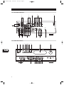
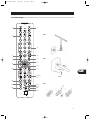
T741 manual (GB)
22/10/01
3:56 pm
Page 1
T741
AV Surround Sound Receiver
GB Owner’s Manual
T741 manual (GB)
22/10/01
GB
2
3:56 pm
Page 2
T741 manual (GB)
22/10/01
3:56 pm
Page 3
NOTES ON INSTALLATION.
Your NAD T741 should be placed on a firm, level surface. Avoid placing
the unit in direct sunlight or near sources of heat and damp.
Allow adequate ventilation. Do not place the unit on a soft surface like a
carpet. Do not place it in an enclosed position such a bookcase or cabinet
that may impede the air-flow through the ventilation slots.
Make sure the unit is switched off before making any connections.
The RCA sockets on your NAD T741 are color coded for convenience.
Red and white are Right and Left audio respectively, black for digital
input, yellow for Video Composite and NAD Link.
Use high quality leads and sockets for optimum performance and
reliability. Audio RCA leads will function correctly for video signals,
although it is recommended to use dedicated video leads where possible.
For the digital inputs use dedicated leads for digital signal transfer. Ensure
that leads and connectors are not damaged in any way and all
connectors are firmly pushed home.
For best performance, use quality speaker leads of 16 gauge (1.5mm)
thickness or more.
If the unit is not going to be used for some time, disconnect the plug
from the AC socket.
Should water get into your NAD T741, shut off the power to the unit and
remove the plug from the AC socket. Have the unit inspected by a
qualified service technician before attempting to use it again.
Do not remove the cover, there are no user-serviceable parts inside.
Use a dry soft cloth to clean the unit. If necessary, lightly dampen the
cloth with soapy water. Do not use solutions containing benzol or other
volatile agents.
GB
3
T741 manual (GB)
22/10/01
3:56 pm
Page 4
EXPLANATION OF GRAPHICAL SYMBOLS
The lightning flash with arrowhead symbol, within an equilateral triangle, is intended to alert
the user to the presence of uninsulated “dangerous voltage” within the product’s enclosure
that may be of sufficient magnitude to constitute a risk of electric shock to persons.
The exclamation point within an equilateral triangle is intended to alert the user to the presence
of important operating and maintenance (servicing) instructions in the literature accompanying
the appliance.
PRECAUTIONS
Read the Operating Instructions carefully and completely before operating the unit. Be sure to keep the
Operating Instructions for future reference. All warnings and cautions in the Operating Instructions and on
the unit should be strictly followed, as well as the safety suggestions below.
INSTALLATION
1 Water and Moisture - Do not use this unit near water, such as near a bathtub, washbowl, swimming
pool, or the like.
2 Heat - Do not use this unit near sources of heat, including heating vents, stoves, or other appliances
that generate heat. It also should not be placed in temperatures less than 5°C (41°F) or greater then
35°C (95°F).
3 Mounting surface - Place the unit on a flat, even surface.
4 Ventilation - The unit should be situated with adequate space around it so that proper ventilation is
assured. allow 10 cm (4 in.) clearance from the rear and the top of the unit, and 5 cm (2 in.) from each
side. - Do not place on a bed, rug, or similar surface that may block the ventilation openings. - Do not
install the unit in a bookcase cabinet, or airtight rack where ventilation may be impeded.
5 Objects and liquid entry - Take care that objects or liquids do not get inside the unit through the
ventilation openings.
6 Carts and stands - When placed or mounted on a stand or cart, the unit should be moved with care.
Quick stops, excessive force, and uneven surfaces may cause the unit and cart to overturn or fall.
7 Condensation - Moisture may form on the CD pickup lens when:
• The unit is moved from a cold spot to a warm spot.
• The heating system has just been turned on.
• The unit is used in a very humid room.
• The unit is cooled by an air conditioner.
When this unit has condensation inside, it may not function normally. Should this occur, leave the unit
for a few hours, then try to operate again.
8 Wall or ceiling mounting - The unit should not be mounted on a wall or ceiling, unless specified in
the Operating Instructions.
GB
WARNING! TO REDUCE THE RISK OF FIRE OR ELECTRONIC SHOCK, DO NOT EXPOSE
THIS APPLIANCE TO RAIN OR MOISTURE
This product is manufactured to comply with the radio interference requirements of EEC DIRECTIVE
89/336/EEC and 73/23/EEC
4
T741 manual (GB)
22/10/01
3:56 pm
Page 5
ELECTRIC POWER
1 Power Sources - Connect this unit only to power sources specified in the Operating Instructions, and
as marked on the unit.
2 Polarization - As a safety feature, some units are equipped with polarized AC power plugs which can
only be inserted one way into a power outlet. If it is difficult or impossible to insert the AC power plug
into an outlet, turn the plug over and try again. If it still does not easily insert into the outlet, please call
a qualified service technician to service or replace the outlet. To avoid defeating the safety feature of
the polarized plug, do not force it into a power outlet.
3 AC power cord - When disconnecting the AC power cord, pull it out by the AC power plug. Do not
pull the cord itself.
• Never handle the AC power plug with wet hands, as this could result in fire or shock.
• Power cords should be routed to avoid being severely bent, pinched, or walked upon. Pay particular
attention to the cord from the unit to the power socket.
• Avoid overloading AC outlets and extension cords beyond their capacity, as this could result in fire
or shock.
4 Extension cord - To help prevent electric shock, do not use a polarized AC power plug with an
extension cord, receptacle, or other outlet unless the polarized plug can be completely inserted to
prevent exposure of the blades of the plug.
5 When not in use - Unplug the AC power cord from the AC outlet if the unit will not be used for
several months or more. When the cord is plugged in, a small amount of current continues to flow to
the unit, even when the power is turned off.
CAUTION
Modifications or adjustments to this product, which are not expressly approved by the manufacturer, may
void the user’s right or authority to operate this product.
MAINTENANCE
Clean the unit only as recommended in the Operating Instructions.
DAMAGE REQUIRING SERVICE
Have the unit serviced by a qualified service technician if
• The AC power plug has been damaged.
• Foreign objects or liquid have gotten inside the unit.
• The unit has been exposed to rain or water - The unit does not seem to operate normally.
• The unit exhibits a marked change in performance.
• The unit has been dropped, or the cabinet has been damaged
GB
DO NOT ATTEMPT TO SERVICE THE UNIT YOURSELF
OWNER’S RECORD
For your convenience, record the model number and serial number (you will find them on the rear of your
set) in the space provided below. Please refer to them when you contact your dealer in case of difficulty.
Model No. :
Serial No. :
5
T741 manual (GB)
22/10/01
3:56 pm
Page 6
FIG. 1 REAR PANEL CONNECTIONS
6
7
9
8
11
+12V TRIGGER
OUT
2
3
4
5
10
12
FIG. 2 FRONT PANEL CONTROLS
4
3
7
8
9
10
GB
11
6
12
13
14
15
16
17
18
T741 manual (GB)
22/10/01
3:56 pm
Page 7
FIG. 3 REMOTE CONTROL
1
2
FIG. 4
3
4
5
6
7
8
FIG. 5
11
9
10
12
13
GB
14-18
20
19
21
24
23
22
26
25
FIG. 6
7
T741 manual (GB)
22/10/01
3:56 pm
Page 8
REAR PANEL CONTROLS (FIGURE 1)
1. FM & AM ANTENNA
AM ANTENNA - An AM loop antenna is supplied with the T741 and is
required for AM reception. Open the clip terminal lever and insert the
wire from the antenna. Closing the lever will lock the wire in place
(Fig. 5). Test various positions for the antenna, but always ensure the loop
is placed vertically for best reception. Placing the antenna close to large
metal items such as metal shelves or radiators may interfere with
reception.
NOTE
When reception is not satisfactory using the supplied AM loop
antenna alone, connection of an external antenna is recommended.
Do not connect anything other than a loop antenna to the AM
ANTENNA terminal. Do not remove the AM loop antenna. The
antenna cable to the loop antenna must not exceed 3 meters.
FM ANTENNA - A ribbon wire FM antenna is included and should be
connected to the FM connector at the rear of the unit (Fig. 4) using the
‘balun’ adapter supplied. The ribbon aerial should be mounted on a
vertical surface and placed so that it forms a ‘T’.
Experiment with placement of the antenna to find the position that gives
the best signal strength and lowest background noise. An inadequate FM
signal normally results in high levels of hiss, especially in stereo, and
interference from external electrical sources. In areas of poor FM
reception, the tuner section’s performance can be improved by using an
externally mounted FM antenna. A qualified aerial installer will be able to
advise and fit a recommended aerial for your reception conditions.
2. TAPE 1 & CD INPUT
TAPE 1 - Connections for analogue recording and playback to an audio
tape recorder of any type, such as a cassette, reel-reel, DAT, MD or DCC.
Using twin RCA-to-RCA leads, connect to the left and right ‘Audio
Output’ of the tape machine to the TAPE 1 IN connectors for playback.
Connect the left and right ‘Audio Input’ of the tape machine to the TAPE
1 OUT connectors for recording.
GB
CD INPUT - Input for CD player (analogue audio signal) or other line-level
signal source. Use a twin RCA-to-RCA lead to connect the CD player’s left
and right ‘Audio Outputs’ to this input.
3. 5.1 CHANNEL INPUTS
Inputs for the multi-channel audio signals from an external decoder, such
as an MPEG decoder or a DVD player with integrated decoder. Use two
twin RCA-to-RCA lead to connect the decoder’s front left and right
“Audio Outputs” to the Front left and right inputs, and the decoder’s
Surround left and right outputs to the Surround left and right inputs. Use
a third twin RCA-to-RCA lead to connect the decoder’s subwoofer
output to the Subwoofer input and the decoder’s Center channel output
to the Center channel input. Make sure you to follow color coding of the
plugs to ensure that both Center and Subwoofer are connected correctly,
for instance, use the red plugs at either end to connect the center
channel and the white plugs for the subwoofer channel.
4. VIDEO 1 - VIDEO 4 (AUDIO & VIDEO)
Apart from the audio signal, these inputs will also accept a video signal
which will be routed to the Monitor Out sockets (No. 7) for a television
or video projector. The Video 1,2 and 3 inputs also have the option of a
an S-Video connection (using the Mini-Din connector) or the standard
Video Composite connection (using the yellow RCA socket).
The S-Video standard allows for higher quality video signal transfer when
compared to the Video Composite standard. If your video components
have an S-Video connector use dedicated S-Video leads to connect them
to the T741 in the same way as described with the Video composite
equivalents.
A video signal fed to an S-Video input socket will be available on both
the S-Video Monitor Out and Video composite Monitor Out.
VIDEO 1 & VIDEO 2 - Inputs for the audio playback and video signal
from a video device such as a stereo TV, DVD player, satellite cable TV
receiver or a Laser Disc. Using twin RCA-to-RCA leads, connect to the left
and right ‘Audio Out’ of the video device to these inputs. Using a single
RCA-to-RCA lead (Video Composite) or S-Video lead, also connect the
video output of the video device; refer also to the description of S-Video
and Video Composite above in this section. VIDEO 1 & VIDEO 2 can be
used for video playback only. Use VIDEO 3 or VIDEO 4 if you want to
connect a VCR for recording and playback through the T741.
The optical Digital Input 1 (No. 5) is linked to the Video 1 input. Select
Video 1 to hear a source connected to Digital Input 1.
The coaxial Digital Input 2 (No. 5) is linked to the Video 2 input. Select
Video 2 to hear a source connected to Digital Input 2.
VIDEO 3 & VIDEO 4 - Connections for the audio recording and playback
to a VCR or other video recorder. Using twin RCA-to-RCA leads, connect
to the left and right ‘Audio Out’ of the VCR to the VIDEO 3 or VIDEO 4
IN connectors for playback. Connect the left and right ‘Audio In’ of the
VCR to the VIDEO 3 or VIDEO 4 OUT connectors for recording. Using a
single RCA-to-RCA (Video Composite) lead or S-Video lead, also connect
the video output of the VCR to Video In for Video playback. Connect the
Video Input of the VCR to Video Out of the NAD T741 receiver for
recording of video signals. Refer also to the description of S-Video and
Video Composite above in this section.
The coaxial Digital Input 3 (No. 5) is linked to the Video 3 input. Select
Video 3 to hear a source connected to Digital Input 3.
5. DIGITAL AUDIO INPUTS
The T741 has three digital audio inputs to allow for connection of DVD,
CD, Satellite receiver or other digital sources:
Digital Audio Input 1 allows for connection of a digital source with an
Optical output. Use a cable terminated with a TOS Link connector. Digital
input 1 is linked to the Video 1 input.
Digital Audio Inputs 2 & 3 allow for connection of a digital source with a
Coaxial digital output. Use a cable with the right impedance, specifically
designed for the transfer of digital signals. These digital inputs are linked
respectively to VIDEO INPUT 2 and VIDEO INPUT 3.
8
T741 manual (GB)
22/10/01
3:56 pm
Page 9
6. AUDIO PRE-OUTS / SUBWOOFER OUT
AUDIO PRE-OUTS - The NAD T741 receiver has five power amplifiers
built-in to power all the speakers connected to it (Left, Right, Center, Left
Surround, Right Surround). It is also possible to use the T741 as a preamplifier to drive external power amplifiers. This way, you use all the
control functions the T741 provides, such as input select, surround
mode, volume, tone controls, etc., but the external power amplifier
actually powers the speaker connected to it instead of the T741’s
integrated power amplifier for that channel.
NOTE
This unit is designed to produce optimum sound quality when
speakers with impedance within the set’s ranges are connected.
Please check the following information and choose speakers with the
correct impedance for the connections.
Connect the RCA-to-RCA leads from the Front left and Right, Center,
and/or Surround Left and Right Audio pre-out connectors to the external
amplifiers. Connect speakers to the external amplifiers.
CENTER SPEAKER - The terminal marked ‘C’ connects to the center
loudspeaker that is used when the T741 is operated in Dolby* Digital,
DTS, Dolby Pro Logic, EARS surround sound mode or with the 5.1 Ch.
input selected.
NOTES
• Never connect the T741’s speaker outputs and the speaker outputs
of an external amplifier to the same speakers. When headphones are
inserted the signals from all audio pre-out outputs will be muted.
• Before making any connections, check that the T741 and the power
amplifiers it will be connected to are switched off. With volume
turned down to a low level, switch power on only after all
connections have been made.
SUBWOOFER OUT - Unlike for the full range five channels as described
above, there is no power amplifier built-in for an additional subwoofer.
The Subwoofer pre-out allows for connection to a sub-bass speaker
system with its own external or integrated power amplifier (“active”
subwoofers).
7. MONITOR OUT
Composite Video and S-Video outputs for connecting a TV or Video
Monitor to view video sources connected to VIDEO 1 to VIDEO 5. Using
a Video RCA-to-RCA lead, connect the “Video Line In” on the TV or
monitor to the MONITOR OUT.
Note that an S-Video signal will also be available as a Video Composite
signal on Monitor out, if the corresponding source is selected. The
composite video input signals (No. 4; yellow sockets) will also be available
as S-Video signal on the Monitor Out socket. If you use both S-Video and
Video composite sources, you will only need to connect the S-Video
Monitor Out to the television or projector.
8. SPEAKERS: FRONT, CENTER & SURROUND SPEAKERS
FRONT SPEAKERS - Connect the right speaker to the terminals marked
‘FR’ ensuring that the red terminal is connected to the ‘+’ terminal on
your loudspeaker and the black terminal is connected to the
loudspeaker’s ‘-’ terminal. Connect the terminals marked “FL” to the left
speaker in the same way.
FRONT SPEAKERS A: 8 ohms min. per speaker;
CENTER SPEAKER B: 8 ohms min.
SURROUND SPEAKERS: 8 ohms min. per speaker
Connect the center speaker in the same way as described with front
speakers above.
SURROUND SPEAKERS - This connects the Surround loudspeakers that
are used when the T741 is operated in Dolby Digital, DTS, Dolby Pro
Logic, EARS Surround sound modes or with the 5.1 Ch. input selected.
Connect the surround speakers in the same way as described with
FRONT SPEAKERS above; connect the left surround speaker to the set of
terminals marked ‘SL’ and the right surround speaker to the terminals
marked ‘SR’.
NOTE
The Center and/or Surround speakers must be selected as Large or
Small in the Set-up menu “SPK SET” when speakers are connected to
these outputs.
9. SOFT CLIPPING
When any amplifier is driven beyond it’s power output capabilities, a
hard, distorted sound can be heard on very loud sounds. This is caused
by the amplifier cutting off or ‘hard clipping’ the peaks of sound that it
was not designed to reproduce. The NAD Soft Clipping circuit gently
limits the output of the system to minimize audible distortion if the
amplifier is overdriven.
If your listening involves moderate power levels you may leave the Soft
Clipping switch off. If you are likely to play at high levels that exceed the
amplifier’s power capability, then switch Soft Clipping on.
Always use heavy duty (16 gauge; 1.5mm or thicker) stranded wire to
connect loudspeakers to your T741. Unscrew the speaker terminal’s
plastic bushing. Insert the bare cable end into the hole of the terminal and
then secure the cable by tightening down the terminal’s bushing (Fig. 6).
To avoid any danger of bare metal from the speaker cables touching the
back panel or another connector, ensure that there is only 1/2” (1.27cm)
of bare cable and no loose strands of speaker wire.
9
GB
T741 manual (GB)
22/10/01
3:56 pm
Page 10
10. NAD-LINK IN OUT
The NAD-Link connector is used to pass commands from other units fitted
with NAD-Link connectors. This allows centralized control of a complete
system, and also allows some of the basic functions of other NAD
components (such as a CD player) also equipped with NAD-Link to be
controlled with the receiver’s remote control. To function with such other
units, connect the T741’s NAD-Link Out to the NAD-Link In on the other
unit. NAD-Link connectors can be daisy-chained, IN to OUT, so that a whole
system can be controlled from the remote control facilities of one unit.
NOTES
• It is advisable not to connect NAD-Link if these units that have their
own built-in remote control command receiver and are positioned
together, in direct view from the remote control handset. If you are
unsure, try operating the products without NAD-Link first; If the unit
responds to the remote control command, it will not be necessary to
connect NAD-Link.
• Never loop the last unit back to the first NAD unit in the NAD-Link
chain.
• Unplug all units from the mains before connecting or disconnecting
NAD-Link.
11. AC POWER CORD
After you have completed all connections to the amplifier, plug the AC
line cord into a “live” wall socket.
12. 12 VOLT TRIGGER OUT
The 12V trigger output allows to remotely switch on or off ancillary
equipment such as a CD player, power amplifier, etc. which are also
equipped with a 12V trigger input. This can also be an AC outlet power
strip equipped with a 12V trigger input. The 12V trigger output is
activated whenever the T741 is switched to normal operational mode
from Stand-by or Off.
GB
For switching Stand-by/Power On of the external component, connect
the 12V trigger output of the T741 to the remote component’s DC input
jack. The plug required is a standard 3.5mm Mini-Jack plug (“mono”):
The tip is the live or + connection, the shaft of the jack is the 12V trigger
- or ground connection.
NOTES
• Check the specifications of the trigger input terminal on the other
component to ensure it is compatible with the T741’s 12V trigger
output.
• The T741’s 12V trigger output voltage is 12V DC. The total maximum
current must not exceed 200mA. Typically, NAD 12V input triggers
draw less then 10mA of current.
• NAD components equipped with 12V input triggers are fully
compatible with the T741’s 12V trigger output.
• Before making any connections to any 12V trigger input or output,
make sure all components are disconnected from the AC mains.
Failure to observe the above may result in damage to the T741 or any
ancillary components attached to it. If in doubt over the connections,
installation and operation of the 12V trigger output consult your NAD
dealer.
10
FRONT PANEL CONTROLS (FIGURE 2)
1. POWER
Press the POWER button to switch the receiver to STANDBY mode. Press
any input selector button on the front panel or the POWER button (No. 1)
on the Remote Control to switch the receiver fully on. The display will
light up indicating which input was selected; the Stand-by indicator will
extinguish. Pressing the POWER switch again will turn the unit OFF
completely. The NAD T741 receiver uses a memory back-up system to
store surround sound trim settings and Preset station information for the
tuner section. This information is retained for several weeks, even the
unit is switched off completely or unplugged.
REMOTE CONTROL
Power button - Press this button to switch the unit from operating to the
Stand-by mode and vice versa. Press this button again to switch to unit on
from Stand-by; the last selected source will be indicated in the display.
NOTE
Stand-by mode is indicated by the Stand-by indicator (No. 2) just over
the green Power button on the front panel (No. 1).
In Stand-by mode the T741 uses very little power. However, it is
recommended that you switch the unit totally off if it is not going to be
used for more than a couple of days. Switch off completely by pressing
the Power button on the front panel (No. 1), all lights will extinguish.
2. STAND-BY INDICATOR
This green LED will light up when the receiver is switched On, but in
Stand-by mode. Refer to section 1 in this chapter for more information.
3. DISPLAY
The T741’s FM tuner supports RDS PS and RDS RT. With stations carrying
RDS information, “RDS” will light up in the display panel, and the
station’s RDS name is automatically displayed (RDS PS).
Some radio stations, which support RDS, also transmit additional
information, known as Radio Text (RDS RT). To view this information, use
the Display button. With stations carrying RDS information, the DISPLAY
button scrolls between three different display modes, each successive
push of the button engages the next one of the three modes:
a) In the default mode, the station’s RDS name is displayed, Program
Service (PS; normally the station’s calling letters, BBC R3, for instance).
b) From the default mode, press the button once to view Radio Text (RT).
This can be additional information such as the presenter’s or
program’s name; what song is playing, etc. This text scrolls
continuously over the 8 alphanumeric display segments. It takes a
few seconds for the tuner to gather the RT information, so
immediately after tuning to a station and selecting to view RT the
display will indicate “NO TEXT” and default to the station name. If no
RT information is available, the display will also show “NO TEXT” for
three seconds before reverting to the default mode.
c) Press the button from the display RT mode to display the station
frequency. Press again to return to the default mode (a).
When the DISPLAY button is pressed when tuned to a non-RDS station
the display will show “NO NAME” for three seconds before reverting to
the default display.
T741 manual (GB)
22/10/01
3:56 pm
Page 11
4. FM/AM
The FM/AM button switches the tuner section from the AM band to the
FM band and vice-versa. The Display Panel shows the frequency of the
tuned station and which band is selected. The FM tuning is in 0.05 MHz
increments, AM tuning is in 9 kHz or 10kHz increments, depending on
the version (9 kHz for the 230V version or 10 kHz for the 120V version).
To change the AM increment tuning steps, press the FM/AM and CD
buttons at the same time.
5. FM MUTE / MODE
This button combines two functions; it switches the tuner from FM
Stereo to Mono mode and disengages the muting circuitry at the same
time. The muting circuit will mute the tuner in between radio stations
when searching or tuning. This way the tuning noise is avoided.
Very weak radio station signals however may be suppressed by the
muting circuit. if such a very weak station is in stereo it will have a high
level of background hiss. Switching to Mono and disengaging the
muting circuit by depressing the FM MUTE/MODE button will allow the
station to be heard and will cancel most or all of this background noise.
In normal operation the mute circuit is engaged, the display indicates
“FM MUTE”. Press the FM Mute/Mode button to disengage the muting
circuit and switch from stereo to mono reception. “FM MUTE” will
extinguish in the display. Also, “FM STEREO” will extinguish if a stereo
broadcast was received. Press the FM Mute/Mode switch again to return
to Auto Stereo FM operation.
In combination with the MEMORY button (No. 6) and DOWN/UP buttons
(No. 8) a preset number can be emptied. (Refer to the separate chapter
“Storing and Recalling Presets” for more information.)
6. MEMORY
The Memory button is used to store stations into the Preset Memory (130 Presets on FM, 1-10 Presets on AM), used in conjunction with the
Down/Up (No. 8) buttons on the front panel. In combination with the FM
MUTE/MODE button (No. 5) and DOWN/UP buttons (No. 8) a preset
number can be emptied. When Memory is active, the Preset number
flashes and the red “MEMORY” indicator is shown in the Display Panel.
If no other button is pressed within 10 seconds “MEMORY” will stop
flashing and the receiver will default to its previous state.
Refer to the separate chapter “Storing and recalling Presets” for more
information.
7. PRESET / TUNE
The Preset/Tune button toggles between the Preset and Tune mode.
When Preset mode is selected, “PRESET” lights up in the display area.
Up to 40 Presets, either AM (10 Presets) or FM (30 Presets), can be stored.
Refer also to separate chapter “Storing and Recalling Presets” for more
information.
8. DOWN / UP
AND
The function of these buttons depends on the tuning mode selected with
the Preset/Tune button (No. 7). The Preset/Tune button toggles between
the two operation modes:
a) Preset mode (indicated in the display area): Press the
(down)
button to scroll to a lower number Preset; press the
(up) button
to scroll to a higher Preset number. This is a “wrap-around” function,
so that going from the highest number Preset, the tuner will go to
the lowest Preset number or vice-versa when tuning either up or
down.
b) Tune mode: Press the
(down) or
(up) button for more
than 1/2 second to engage automatic tuning respectively up or down
the frequency band. The tuner will search automatically for the first
reasonably strong radio station, where it will stop. Press the Down/Up
button again for 1/2 second to start searching again.
NOTE
Automatic tuning is available on both FM and AM.
By briefly tapping the
(down) or
(up) buttons you can engage
manual tuning respectively down or up the frequency band for precise
tuning to a specific frequency. With each successive tap of the keys, the
tuner will take 0.05 MHz steps on FM so you can accurately tune into the
desired frequency.
This tuning mode can also be useful when trying to receive a radio
station which is too weak for the auto search mode. When tuned
accurately to a station, “
TUNED
” will light up in the display.
Very weak radio station signals however may be suppressed by the
muting circuit. If such a very weak station is in stereo it will have a high
level of background hiss. Switching to Mono and disengaging the
muting circuit by depressing the FM MUTE/MODE button (No. 5) will
allow the station to be heard and will cancel most or all of this
background noise.
Refer to the separate chapter “Storing and Recalling Presets” for more
information.
9. VFL DISPLAY
Vacuum Fluorescent Display. The display area will show all vital
information when the unit is operational.
10. VOLUME & SET UP
In the default function, this control acts as a Volume control, adjusting
the overall loudness of the signals being fed to the loudspeakers and
headphones. Unlike conventional controls, the T741’s volume control
doesn’t have a start or end position. Volume can also be adjusted from
the remote control handset using the Master Volume Up or Down
buttons. The Volume control does not affect recordings made using the
Tape, Video 3 and Video 4 outputs but will affect the signal going to the
Pre-amp output (Audio Pre Out). The volume level is indicated in the
display panel when it is being adjusted. After three seconds the display
defaults to its previous status. Volume setting can range from
– ∞ to +18dB.
On the remote control handset, press the Mute button to temporarily
switch off the sound to the speakers and headphones. Mute mode is
indicated by “MUTING” flashing in red in the display area. Press Mute
again to restore sound. Mute does not affect recordings made using the
Tape, Video 3 and Video 4 outputs but will affect the signal going to the
Pre-amp output (Audio Pre Out) and headphones.
11
GB
T741 manual (GB)
22/10/01
3:56 pm
Page 12
The control is also used to adjust various set-up settings and levels for the
T741. In conjunction with the SETUP button (No. 17) the speakers size
and delay can be adjusted; in conjunction with the Tone Control button
(No. 18) the Bass and Treble levels can be adjusted. Refer also to sections
“SETUP” and “Tone controls” in this chapter.
11. HEADPHONE SOCKET & VIDEO 5 INPUT
HEADPHONE SOCKET - A 1/4” stereo jack socket is supplied for
headphone listening and will work with conventional headphones of any
impedance. The volume and tone controls are operative for headphone
listening. Use a suitable adapter to connect headphones with other types
of connectors such as 3.5mm stereo ‘personal stereo’ jack plugs.
Inserting a headphone will automatically turn off all speakers and signals
from the Audio Pre-Out sockets and switches the T741 to the stereo
mode. Surround sound modes are not available when headphones are
inserted in the headphone socket.
The sound from the EXT. 5.1 CH input is not available on the headphones
socket.
NOTES
• In the VFL display “Speaker settings”, be sure to have selected and
adjusted a preset with “MAIN SPEAKERS” set to “LARGE”. If set to
“SMALL”, bass response will be limited.
• Listening at high levels can damage your hearing.
VIDEO 5 INPUT - For easy and temporary connection you can connect a
camcorder (playback only) or video game console. If the game console or
camcorder is mono, connect the audio lead to the R (Right) audio socket.
12. AUDIO & VIDEO INPUT SELECTORS
VIDEO 1 - Video 1 selects the signal from a TV/Satellite/Cable receiver or
DVD player connected to VIDEO 1 as the active input. “VIDEO-1” is
shown in the Display Panel when selected.
GB
The Digital Input 1 is linked to the Video 1 input (marked Digital In 1 on
back panel; No. 6). Digital Input 1 allows for connection of a digital
source with an Optical (Toslink) digital output. Whenever the
corresponding digital input is activated, Digital Input 1 will also be
selected; in the display the “DIGITAL 1” indicator will start to blink. If a
digital audio signal is detected, the “DIGITAL 1” indicator will stop
blinking and remain lit. If no digital audio signal is detected, “DIGITAL 1”
indicator will cease blinking and extinguish.
VIDEO 2 - Video 2 selects the signal from a TV/Satellite/Cable receiver or
DVD player connected to VIDEO 2 as the active input. “VIDEO-2” is
shown in the Display Panel when selected.
The Digital Input 2 is linked to the Video 2 Input (marked Digital In 2 on
back panel; No. 5). Digital Input 2 allows for connection of a digital
source with an coaxial (RCA Jack) digital output. Whenever the
corresponding digital input is activated, Digital Input 2 will also be
selected; in the display the “DIGITAL 2” indicator will start to blink. If a
digital audio signal is detected, the “DIGITAL 2” indicator will stop
blinking and remain lit. If no digital audio signal is detected, “DIGITAL 2”
indicator will cease blinking and extinguish.
12
VIDEO 3 & VIDEO 4 - Video 3 & 4 select the signal from a
TV/Satellite/Cable receiver, DVD player or VCR connected to VIDEO 3 or
VIDEO 4 as the active input. “VIDEO-3” or “VIDEO-4” is shown in the
Display Panel when selected. The Video 3 & 4 inputs also have video and
analogue audio outputs specifically for recording video devices.
The Digital Input 3 is linked to the Video 3 input (marked Digital In on
back panel; No. 5). Digital Input 3 allows for connection of a digital
source with a Coaxial (RCA Jack) digital output. Whenever the
corresponding digital input is activated, Digital Input 3 will also be
selected; in the display the “DIGITAL 3” indicator will start to blink. If a
digital audio signal is detected, the “DIGITAL 3” indicator will stop
blinking and remain lit. If no digital audio signal is detected, “DIGITAL 3”
indicator will cease blinking and extinguish.
VIDEO OUTPUT - The video signal available on the S-Video and Video
Composite outputs is dependent on the selected video input (VIDEO-1,
VIDEO-2, VIDEO-3, VIDEO-4, VIDEO-5). However, when one of the
audio-only sources is selected (FM, AM, CD, Tape Monitor or Ext. 5.1) the
last selected video signal from one of the video inputs will be present on
these outputs. This way you can watch a DVD player or video whilst
listening to the CD player.
The display indicates which video signal is routed to the MONITOR OUT
sockets (No. 7 on back panel).
13. CD
Selects the CD as the active input.
14. TAPE MONITOR
Selects the output from a tape recorder when playing back tapes or
monitoring recordings being made through the Tape sockets. Press the
TAPE MONITOR button once to select it and again to return to the
normal input selection.
The Tape Monitor function does not override the current input selection.
For example, if the CD is the active input when Tape Monitor is selected,
the CD signal will continue to be selected and is sent to the Tape Out,
Video 3 and Video 4 Out sockets. But it is the sound from recorder
connected to Tape that will be heard on the loudspeakers when the TAPE
MONITOR function is selected. When Tape Monitor is selected, “TAPE
MONITOR” will remain lit until Tape Monitor is disengaged again.
15. EXT. 5.1
Selects the multi-channel output signal from the DVD player or external
decoder source (such as MPEG, for instance) connected to the 5.1 Ch.
Input as the active input. The 5.1 Input is a direct pass through with only
the volume control in the circuit. Bass management settings and tone
controls are not available on this input.
NOTE
No Ext. 5.1 audio signal is available from headphones socket, the Tape,
Video 3 and Video 4 out-puts when the Ext. 5.1. input has been selected.
T741 manual (GB)
22/10/01
3:56 pm
Page 13
16. SURROUND MODE
With the Surround Mode buttons the available surround sound modes
can be selected. The selected Surround mode is permanently indicated in
the display Area. The Surround Mode buttons scroll through the available
surround sound modes:
17. SET UP
This button is used to configure the T741 to match with the specific
speakers in your system. This setup procedure should be done when you
first install your system, and subsequently when new or different
speakers are attached, or when the speaker positions are changed.
With any of the Digital Inputs 1, 2 & 3 (press Video 1, 2 or 3 respectively
to select), the T741 automatically recognizes if the selected source carries
a Dolby Digital™ or DTS™ signal. When no Dolby Digital or DTS signal
is available, the Surround Mode buttons scrolls through the other
available surround sound modes:
The SET UP facility uses a “menu” system that is 3 layers deep to
accomplish the speaker setup. The Front Panel display will give you
feedback on where you are in the menu system at any given moment.
By first pressing the SET UP button and then turning the VOLUME/SETUP
knob all menu items can be accessed.
Stereo ➜ Pro Logic ➜ Ears ➜ Stereo, etc.
SET UP OPTIONS
With either Dolby Digital or DTS surround mode engaged, the Dolby Pro
Logic and Ears surround modes cannot be selected. Dolby Digital and
DTS has six independent channels available in total: Left, Center, Right,
Surround left, Surround Right and an “Effects Channel” (Subwoofer).
The Dolby Digital signal allows for several channel configurations. DTS
digital surround is an Encode/Decode system that currently delivers six
discrete channels (5.1) of “Master-Quality” up to 24-bit audio. Dolby Pro
Logic decodes the center and surround sound signals embedded in stereo
movie sound tracks from e.g. video, Laser Disc or TV. To decode correctly,
the source must be a Dolby Surround or Dolby Stereo soundtrack.
In the EARS (Enhanced Ambiance Retrieval System) Surround Mode, a
realistic level of ambience of surround sound is added to a normal stereo
source such as a CD or FM radio.
NOTES
• Dolby Digital or DTS are only available as a Surround Mode if the
source is either Dolby Digital or DTS and a Digital Audio input is used.
• An external source such as a decoder or DVD player with a decoder
built-in (MPEG for instance) can be connected to the 5.1Ch input (No.
3 on the rear panel). When the EXT 5.1 CH. input is selected, no other
surround modes are available.
To obtain the best performance possible it is important that the system
and all speakers have been set up correctly.
(Layer 1) SPK SET
(Layer 2) MAIN
(Layer 3)
(Layer 3)
(Layer 2) CEN
(Layer 3)
(Layer 3)
(Layer 3)
(Layer 2) REAR
(Layer 3)
(Layer 3)
(Layer 3)
(Layer 2) SUB
(Layer 3)
(Layer 3)
(Layer 2) EXIT
(Layer 1) DELAY
(Layer 2) CEN
(Layer 3)
(Layer 2) REAR
(Layer 3)
(Layer 2) EXIT
(Layer 1) EXIT
LAR
SMA
LAR
SMA
OFF
LAR
SMA
OFF
ON
OFF
0mS (Time in mS)
0mS (Time in mS)
To access the SET UP menu, press SET UP button to go to Layer 1, SPK SET.
Use VOLUME/SET UP knob to change selection at Layer 1. Press SET UP
button to enter Layer 2. Use VOLUME/SET UP knob to change selection at
Layer 2. Press SET UP button to enter Layer 3. Use VOLUME/SET UP knob
to change selection at Layer 3. While at Layer 3, press SET UP button to
exit Layer 3 and go back to Layer 2. While at Layer 2 or Layer 1, selecting
Exit then pressing SET UP will go back one level up. After a 5 sec default
time, if no adjustment is made, the T741 will automatically exit the set up
mode and return to the last selected input.
Refer to section SETTING UP A SURROUND SYSTEM below for more
detailed information on making these adjustments.
18. TONE CONTROLS
This button is used to adjust Bass and Treble response to suit personal
taste, or to compensate for less than optimal program sources. Each
press of the TONE CONTROLS button cycles through BASS ➜ TREB
➜ and back to the previously selected input. Adjustment of Bass and
Treble response is accomplished by turning the VOLUME/SET UP knob.
Adjustment can be made in 2 dB increments up to +/- 10 dB. After a 5
sec default time, if no adjustment is made, the T741 will automatically
exit the TONE CONTROLS mode and return to the last selected input.
13
GB
T741 manual (GB)
22/10/01
3:56 pm
Page 14
STORING AND RECALLING PRESETS
TO STORE A PRESET
• Tune to the radio station you wish to enter into a Preset (refer to
chapter “Front Panel Controls”; section 8). If the station is
transmitting RDS information, the RDS indicator will light up and
station initials will be shown in the Display Panel. If a non-RDS station
is found, then just the frequency will be shown.
• To store that station as a Preset, press MEMORY (No. 6). “MEMORY”
and the preset section in the display panel will start to flash. If no
other button is pressed within 10 seconds, “MEMORY” will stop to
flash and the receiver will default to its previous state.
• Press either the
(down) or
(up) button to select which
Preset number you wish to assign to the station (from 1 to 30 on FM
and 1 to 10 on AM), shown as a flashing number in the Display Panel,
and then press MEMORY (No. 6) again. The Memory light in the
Display Panel will go out and the station is now stored in your NAD
T741’s memory.
To exit the Memory mode without storing a station, leave all the tuner
controls untouched; the Memory mode will automatically cancel itself
after 10 seconds. The Memory Presets have a memory back-up, so they
will remain stored for several weeks even if the Receiver is switched off or
unplugged from the mains supply.
NOTE
You can enter a new station into an unused Preset or over-write an
existing programmed Memory Preset. By doing this you will replace
the radio station previously held on that Preset number.
RECALLING A PRESET STATION
To select a Preset station:
• Select the Preset mode by pressing the PRESET/TUNE button (No. 7)
until “PRESET” lights up in the display.
• Press either the
(down) or
(up) button (No. 8) until the
right Preset is found and shown in the Display Panel.
GB
NOTE
Any unused Presets will be skipped.
To “Directly Access” a Preset Station from the Remote Control:
Press the numeric key on the Remote Control (AVR-1) the Preset number
selected flashes in the Front Panel display window for 2 secs allowing for
a valid second key entry for presets 10 and above.
DELETING A STORED PRESET
You can empty a Preset by deleting the stored information:
• Press MEMORY button (No. 6).
• Press DOWN/UP buttons (No. 8) to select the preset number to be
deleted.
• Press the FM MUTE/MODE button (No. 5). The Preset will then be
deleted and ‘—’ appears as the Preset number.
You can also store a new station into a used Preset, by simply going
through the Preset storing process and placing a new station over the
existing one.
REMOTE CONTROL AVR-1 (FIGURE 3.)
The T741 is supplied with the NAD AVR-1 Remote Control. Apart from
all the primary operating functions, the AVR-1 Remote Control handset
also gives access to functions not available on the front panel of the
T741. It also has additional controls to remotely operate NAD T550, L55,
T531 and T571 DVD Players. The function of the buttons will change
between the T741 Receiver and the NAD DVD Player depending on the
position of the RCVR/DVD switch (See 25 below). Shared buttons
(buttons that function with the switch in either position) have the
receiver function printed on the button itself, with the secondary DVD
function printed on the body of the remote handset
Alkaline batteries are recommended for maximum operating life. Two
AAA (R 03) batteries should be fitted in the battery compartment at the
rear of the Remote Control handset. When replacing batteries, check
that they have been put in the right way round, as indicated on the base
of the battery compartment. It will operate up to a distance of 16ft (5m).
1. POWER
Press this button to switch the unit from operating mode to the Standby mode and vice versa:
Press this button again to switch the unit on from Stand-by; the last
selected source will be indicated in the display.
2. SLEEP
Press SLEEP to make the T741 automatically switch off after a preset
number of minutes. Pressing the SLEEP button once will set the sleep
time to 90 minutes, after which the T741 will automatically switch off
into Standby mode. Sleep mode is shown on the Display Panel. To adjust
the Sleep Delay, press the SLEEP button, each consecutive press will
reduce the sleep time in 30-minute increments, as shown in the Display
Panel. To cancel the Sleep mode, continue pressing the SLEEP button
until the sleep time returns to 0 minutes. Pressing the POWER on the
front panel (No.1) or POWER button on the remote control (No. 1) will
also cancel the Sleep mode.
3. INPUT SELECTION
The EXT 5.1, VIDEO 1 TO 5, TAPE MON, FM/AM and CD Input selector
buttons perform the same function as those on the front panel of the
T741.
14
T741 manual (GB)
22/10/01
3:56 pm
Page 15
4. NUMERIC KEYPAD
RCVR mode - The numeric keypad can be used to directly access FM and
AM Station Presets by pressing the number of the desired preset.
DVD mode - These keys can also be used to select CD tracks and enter
chapter numbers in the DVD mode (consult the DVD Players instruction
manual for specific details).
5. SURROUND / SETUP
SURR. Function - This button sequentially cycles through the available
surround modes: STEREO ➜ PROLOGIC ➜ EARS ➜ and “wraps” back
to STEREO. Each press of the button advances the T741 to the next
surround mode. DOLBY DIGITAL and DTS are automatically detected on
the incoming signal and selected.
SETUP Function - Accesses the DVD Players SETUP Menu. Refer to the
NAD DVD player Owner’s Manual for more detailed information on this
function.
6. DYNAMIC RANGE / NEXT DISC
The DYN. R button, which can be used only in combination with a Dolby
Digital source, incrementally reduces the audio track’s dynamic range in
four steps (100%, 75%, 50% and 25%) to allow for comfortable listening
under a variety of conditions. The normal or default position is 100%.
TITLE functions when in the DVD mode to display the title screen
included on DVD video discs. Refer to the NAD DVD player Owner’s
Manual for more detailed information on this function.
8. LEVEL / MENU
Although the T741 is correctly set-up it may some-times be desirable to
make minor adjustments to suit particular software. Pressing the Level
button allows for direct adjustment of individual channel levels. Press the
Level button to scroll to Front Left, Center, Front Right, Rear Right, Rear
Left and Subwoofer. The display panel shows which speaker can be
adjusted. Use the VOLUME+/- buttons to respectively increase or
decrease the level for the current speaker.
Refer also to the chapter “Setting Up the Surround Sound System” for
more information.
Use the MENU in DVD mode to display the menu screen included on
DVD video discs. Refer to the NAD DVD player Owner’s Manual for more
detailed information on this function.
To adjust the dynamic range, each consecutive press of the DYN. R
button will reduce the value in 25% increments, as shown in the alphanumeric display section.
9. VOLUME / ARROW
Volume + or - respectively increases or decreases the volume setting for
all speakers. The display panel will indicate the level set. The Volume
control does not affect recordings made using the Tape and Video, or
Tape, Video 3 and Video 4 out-puts but will affect the signal going to the
Pre-amp output (Audio Pre Out) and headphones.
NEXT DISC functions with a DVD Changer (NAD T571) to select the next
disc loaded in the carousel. Each press of the button advances by one
disc. Refer to the NAD DVD player Owner’s Manual for more detailed
information on this function.
In DVD mode, these keys function as the UP and DOWN ARROW keys
used for navigating the various graphical user interface (GUI) menus on
both the DVD player and DVD Video discs. Refer to the NAD DVD player
Owner’s Manual for more detailed information on this function.
NOTE
Although we usually prefer to reproduce a source’s full dynamic
range (the difference between very loud and very soft sounds), it may
occasionally be desirable to reduce the dynamic range. For example,
when playing a movie late at night, loud explosions might wake
sleeping family members. Simply turning the volume control down
would probably make a whisper in the next scene inaudible. The
DYN. R button solves this dilemma by progressively lowering the
volume of loud peaks while increasing the level of softer sounds.
10. MUTE / ENTER
Press the MUTE button to temporarily switch off the sound to the
speakers and headphones. Mute mode is indicated by “MUTING”
flashing in red in the display area. Press MUTE again to restore sound.
Mute does not affect recordings made using the Tape out-puts but will
affect the signal going to the Audio Pre-outs and headphones.
7. TEST / TITLE
Pressing the TEST button, engages the Test signal generator to allow for
adjustment of all speaker levels, so that each channel can be adjusted for
equal loudness at your listening position. The test signal scrolls
automatically with 2 second intervals from Front Left, Center, Front Right,
Rear Right, Rear Left, to subwoofer in continuous cycles. If an adjustment
in setting is made for one of the speakers, scrolling will stop until
2 seconds after the adjustment was made. The display panel shows
which speaker is being fed with the test signal. Use the VOLUME +/buttons to respectively increase or decrease the level for the current
speaker. Press the TEST button again to leave or cancel the Test mode,
any changes will be memorized automatically.
Refer also to chapter “Setting Up the Surround Sound System” for more
information.
NOTE
When the unit is in mute mode, any adjustment of the VOLUME
CONTROL on the front panel (No.10) or Remote Control (No. 9) will
release the muting, i.e. the original volume level will be resumed.
11. TUNE UP / TUNE DOWN AND ARROW
/ ARROW
TUNE UP/ TUNE DOWN functions the same as the button of the front
panel of the T741. See complete description in the FRONT PANEL
CONTROL S section above.
In DVD mode, these keys function as the UP and DOWN ARROW keys
used for navigating the various graphical user interface (GUI) menus on
both the DVD player and DVD Video discs. Refer to the NAD DVD Player
Owner’s Manual for more detailed information on this function.
12. DISPLAY
The DISPLAY button functions the same as the DISPLAY button on the
front panel of the T741. See complete description in the FRONT PANEL
CONTROLS section above.
In DVD mode this button displays information about player settings using
the graphical user interface (GUI). Refer to the NAD DVD Player Owner’s
Manual for more detailed information on this function.
15
GB
T741 manual (GB)
22/10/01
3:56 pm
Page 16
13. TUNE MODE / RETURN
The TUNE MODE button functions the same as the button of the front
panel of the T741, switching between the Tune Mode and the Preset
Mode. See complete description in the FRONT PANEL CONTROLS section
above.
In DVD mode this button’s function is determined by the individual DVD
disc title being played. Refer to the NAD DVD Player Owner’s Manual for
more detailed information on this function.
14. OPEN / CLOSE
Opens or closes the loading tray of the DVD player.
15. STOP
Stops play of the DVD player.
16. PLAY
Commences playback of DVD or CD discs loaded in the DVD player.
17. PAUSE / STEP
With CD discs this button pauses playback. With DVD video discs this
button places the player in the still picture mode, and each successive
press of the button advances (STEPs) the picture by one frame. Press the
PLAY button to return to normal playback.
18. SKIP
/ SKIP
This button advances or moves back a chapter (DVD) or track (CD) each
time the button is pressed.
19. REPEAT
Repeats a program or an entire DVD or CD disc.
20. SCAN
/ SCAN
This button scans fast forward or back with DVD or CD discs. Each time
the button is pressed the speed of scanning is increased. Press PLAY to
return to normal playback.
GB
21. PROGRAM
This button is used to create playback programs on CD discs.
22. AUDIO
This button changes the audio soundtrack language on DVD video discs
that support this feature.
23. SUBTITLE
This button changes the subtitle language on DVD video discs that
support this feature.
24. CLEAR
This button is used to defeat or clear repeat play programs.
25. RECEIVER/DVD SWITCH
This switch changes the function of the keys on the remote from the
T741 RECEIVER commands to the DVD Player commands. This remote
includes the codes for use with NAD T531, T571, T550, and L55 DVD
Players only.
26. ZOOM
The ZOOM function allows you to enlarge a selected portion of the video
image (close up).
16
27. DVD1 / DVD2 SWITCH
This switch is located inside the battery compartment of the AVR-1, and
changes the DVD functions between DVD1 (codes for T550 and L55
DVD Players) and DVD2 (codes for T531 and T571 DVD Players).
SETTING UP THE SURROUND SYSTEM
To obtain the best results in any of the Surround Modes it is important
that the T741 is carefully set up. The Dolby Surround system requires
that you specify the parameters of your speaker setup so it can properly
direct the decoded surround sound signal in the correct proportion to
create the most accurate theatrical effect. Dolby also allows for the
redirection of bass frequencies to the most appropriate speaker(s). This
is also known as “bass management”.
The setup procedure is broken down in three sections:
1 Speaker Settings (by Front Panel controls)
2 Channel Delays (by Front Panel controls)
3 Level Settings for correct Channel Balance (by Remote Control
handset)
SPEAKER SETTING OPTIONS
SPK SET
MAIN
CENT
REAR
SUB
EXIT
LAR or SMA
LAR, SMA, OFF
LAR, SMA, OFF
ON, OFF
DELAY
CEN
REAR
EXIT
(0-5 mS )
(5-30 mS )
TO ACCESS THE SPEAKER AND DELAY SETTING
ADJUSTMENTS
Pressing the front panel SET UP button (first press) the display will show
SPK SET. Rotating the VOLUME/SETUP knob alternately cycles the setting
between SPK SET, DELAY , EXIT, and then “wraps” back to SPK SET.
Speaker Settings - First you need to indicate which speakers are
connected to your T741. Besides the Main speakers (Left & Right), these
can include a Center, two Surround Speakers and a Subwoofer.
To Adjust Speaker Settings - When Front Panel Display shows SPK SET,
pressing the SET UP button on front panel again (second press) will enter
the SPEAKER SETTING menu. Rotate VOLUME/SETUP knob to cycle
between MAIN ➜ CEN ➜ REAR ➜ SUB ➜ EXIT
First stop at MAIN and display shows LAR (current setting for FRONT or
MAIN speakers). Press the SET UP button again to change the size. Each
press of the SET UP button will change the setting for that speaker:
MAIN (Front Speakers) can be selected as LRG or SML
Now rotate the VOLUME/SETUP knob until CEN LAR (current setting for
the CENTER speaker) appears in the display window. Press the SET UP
button again to change the size. Each press of the SET UP button will
change the setting for that speaker:
CEN (Center Speaker) can be selected as LAR, SMA or OFF.
T741 manual (GB)
22/10/01
3:56 pm
Page 17
Now rotate the VOLUME/SETUP knob until REAR LAR (current setting for
the SURROUND speakers) appears in the display window. Press the SET
UP button again to change the size. Each press of the SET UP button will
change the setting for that speaker:
REAR (Surround Speakers) can be set to LAR, SMA or OFF.
Now rotate the VOLUME/SETUP knob until SUB ON (current setting for
the Subwoofer) appears in the display window. Press the SET UP button
again to change the setting. Each press of the SET UP button will change
the setting for that speaker:
SUB (subwoofer) can be set to ON, OFF.
Now rotate the VOLUME/SETUP knob until EXIT appears in the display
window. Press the SET UP button again to exit SPEAKER SETTING MENU.
Press the SET UP button again to exit the SET UP MENU. Your speaker
settings are now complete. If in the future you add or change speakers,
this setup procedure should be repeated.
TIPS ON WHICH SPEAKER SETTINGS TO USE
The four modes available to the T741’s setup are: LARGE or SMALL and
ON or OFF.
The LARGE mode is used when the speaker is full range and capable of
reproducing the entire audible frequency spectrum 20Hz to 20kHz. The
SMALL mode is used when the speaker is not capable of reproducing the
deepest bass portion of the audio frequency 20Hz to 100Hz.
The ON mode is used when the speaker is active and receives the audio
information intended. The OFF mode is used when the speaker is
inactive. Audio signals intended for speakers set to the OFF position are
redirected to the main speakers.
Using a separate center channel speaker will allow the dialogue to cut
through even the biggest sound effects and musical scores. Having the
sound spread across three front speakers also stabilizes the stereo image,
making the usable listening area much bigger. For best results, you
should consider using a center speaker. Ideally it should be the same type
as the left and right speakers.
Installing surround speakers will greatly enhance the surround experience
as these add considerably to the overall “ambience”.
Dolby Pro Logic encoded material is deliberately limited in dynamic range
and frequency bandwidth for the surround channel and thus only
requires speakers of far lesser specification compared to the front
channels. Dolby Digital however is a full range system, with two
independent surround channels and with dynamics equal to that of the
front channels. For this reason it is advisable to choose loudspeakers
which are similar in power handling and performance capability to those
of the front channels. For best results, the Surround loudspeakers should
not beam the sound directly at the listener. One way of achieving this is
to use ‘dipole’ Surround speakers which aim the sound down the walls
rather than directly into the room.
Many film soundtracks rely heavily on very low frequency sound effects
which are difficult for normal or smaller hi-fi speakers to reproduce. To
faithfully reproduce these low frequencies you can use a specially
designed low frequency loudspeaker with its own built-in amplifier
(“active subwoofer”). Because it is difficult to hear which direction very
low frequencies are coming from, you only normally need one subwoofer and this can be placed virtually anywhere in the room. The
Subwoofer output of the T741 is designed specifically to drive a
subwoofer system.
Dolby Digital uses a dedicated Low Frequency Effects (LFE) channel. If a
subwoofer has been selected, the LFE channel will be fed to the subwoofer output. If no subwoofer is selected the LFE channel is redirected
to the front left and right speakers.
CHANNEL DELAYS
For the best surround sound performance it is important that sound from
all speakers reach the listener’s ears at the same time. Because the
surround/ rear speakers are usually closer to the listener than the front
speakers, there is tendency for the ear to localize sounds to the rear,
because the ear takes most notice of the sounds that arrive at the head
first. Similarly, the center speaker is often closer to the listener than the
front left and right speakers. To compensate for this, the T741 can
slightly delay the audio sent to the center and rear (closer) speakers. In
this way, when playing Dolby Digital or Dolby Pro logic soundtracks, the
sound from all speakers arrives uniformly at the listening position as
intended by the film’s producer.
Each millisecond corresponds approximately with 1 foot or 30.5
centimeters.
NOTE
The channel delay option is not available in DTS surround mode.
TO ADJUST DELAY SETTINGS
When Front Panel Display shows DELAY, pressing the SET UP button on
front panel again (second press) will enter the DELAY SETTING menu.
Rotate VOLUME/SETUP knob to cycle between CENT ➜ REAR ➜ EXIT.
First stop at CEN 0mS (current delay setting for Center Speaker). Press
the SET UP button again to change the delay setting. Rotate the
VOLUME/SETUP knob to change center delay adjustment in 1mS
increments from 0mS to 5mS. Press SET UP button again to exit Center
delay adjustment.
Now rotate the VOLUME/SETUP knob until REAR 0mS (current delay setting
for Surround Speakers) appears in the display window. Press the SET UP
button again to change the delay setting. Rotate the VOLUME/SETUP knob
to change center delay adjustment in 1mS increments from 0mS to 15mS
in Dolby Digital mode, or 15mS to 30mS in Dolby ProLogic mode. Press SET
UP button again to exit Rear delay adjustment.
Now rotate the VOLUME/SETUP knob until EXIT appears in the display
window. Press the SET UP button again to exit DELAY SETTING MENU.
Press the SET UP button again to exit SET UP MENU. Your speaker
settings are now complete. If in the future you add, change, or move
speakers, this setup procedure should be repeated.
17
GB
T741 manual (GB)
22/10/01
3:56 pm
Page 18
TIPS FOR SETTING DELAY
Measure the distance from the listening position to the center speaker
(dC) and to one of the front speakers (dFL or dFR). Subtract the center
channel distance from the front L or R channel distance. For example, if
the front speakers are 12 feet (3.7 m) from the listening position and the
center speaker is 10 feet (3.0 m), the difference is 2 feet (0.6 m). For this
example the center channel delay is set to 2 milliseconds or ms.
The Channel Balance for each speaker can be adjusted in 1dB
increments. Continue to calibrate the level for each speaker until equal
loudness is achieved at your listening position. A more accurate
adjustment can be made using a sound level meter, if available. Set the
meter to “Slow” and “C-weighted” modes and re-check the settings
with the meter placed in several different positions in the general
listening area.
The T741 can delay the center channel output up to 5 milliseconds and
thus compensates for center channel speakers that are up to 5 feet
(1.5m) closer to the listening position than the front left and right
speakers.
Press the TEST button again to leave or cancel the Test mode, any
changes will be memorized automatically.
NOTES
In rare system setups, the center channel speaker is actually further
away than the front left and right speakers. In these cases, set the
center channel delay to 0mS. The center channel delay time
adjustment is only available in Dolby Digital surround mode.
Measure the distance from the listening position to either the left or right
rear speaker (dLS or dRS). Subtract the rear speaker distance from the
front speaker distance (dFL or dFR). The resulting distance is equivalent to
the delay in milliseconds for the rear delay setting. For example, if your
rear speaker distance is 6 feet (1.8 m) and the front distance is 12 feet
(3.7 m), the correct rear channel delay setting is 6 milliseconds. Again, set
the rear channel delay to 0mS if the rear channels are further from the
listening position than the front speakers.
In Dolby Digital surround mode, the rear channel delay time can be set
from 0ms to 15ms with 1ms increments. In Dolby Pro logic surround mode,
the rear channel delay time can be set from 15ms to 30ms and 1ms per
step. In DTS surround mode, the channel delay time cannot be adjusted.
GB
LEVEL SETTING (CHANNEL BALANCE)
The output levels of each of the speakers connected to the T741 may
need to be adjusted so that there is an even balance of sound from all
the speakers in the system. If, for instance, the relative volume level to
the Left and Right speakers and the center speaker is set too low, most
of dialogue may be difficult to follow. If, on the other hand it is set too
loud, the over-all balance will sound unnatural.
To adjust the channel balance, the T741 is equipped with a TEST button
(No. 7) on the Remote Control to help assess the loudness levels of each
speaker. Before adjusting the channel balance level, make sure the
master volume is turned down to a normal listening level.
Pressing the TEST button engages the Test signal generator to allow for
adjustment of all speaker levels, so that each channel can be adjusted for
equal loudness at your listening position. The test signal scrolls
automatically with 2 second intervals from Left, Center, Right, Rear Right,
Rear Left, to sub-woofer in continuous cycles. If an adjustment in set-ting
is made for one of the speakers, scrolling will stop until 2 seconds after the
adjustment was made. The display panel shows which speaker is being fed
with the test signal. Use the VOLUME +/- buttons on the Remote Control
to respectively increase or decrease the level for the current speaker.
NOTE
There is no output in the Subwoofer during noise sequencer operation;
therefore it is difficult to adjust the level in test mode. The Subwoofer
level can be adjusted in the setup menu with musical input.
18
Select the channel for which you wish to adjust and set the level so that it
matches the other speakers. For best results it is best to start with the Left
channel set at 0dB and to match the other speakers to it. Normally, if the
Right speaker is located at the same distance from the listening position to
the Left speaker it should be set at the same level as the Left speaker.
NOTE
If no level adjustments were made, press TEST again to return to the
selected source. Any changes in the Channel Balance Setting, under
the test mode, will be memorized automatically.
The Delay time for the Surround speakers also needs to be correctly set
for your normal listening position. Refer to the section “Channel Delay”
in this chapter for more information.
T741 manual (GB)
22/10/01
3:56 pm
Page 19
PROBLEM
NO SOUND
CAUSE
•
SOLUTION
•
•
•
Power AC lead unplugged or power not
switched on
Tape Monitor selected
Mute on
NO SOUND ON ONE CHANNEL
•
•
•
Speaker not properly connected or damaged.
Input lead disconnected or damaged
In Setup “OFF” for surround speaker selected
•
•
•
Check connections and speakers
Check leads and connections
Select appropriate Surround mode (large or
small)
NO SOUND ON SURROUND CHANNELS
•
•
No surround mode selected
Mono sound source
•
•
•
•
Speakers not properly connected
Surround volume level too low
•
•
Select a Surround Mode
Test system with Stereo or Dolby Surround
material
Check speakers and connections
Increase surround volume level
NO SOUND ON CENTER CHANNEL
•
•
•
In Setup “OFF” for center speaker selected
Speaker not connected properly
Center volume level set too low
•
•
•
Select appropriate Center mode (large or small)
Check speaker and connection
Increase center volume level
“DOLBY DIGITAL” OR “DTS” AUTO-DETECTION
FUNCTION DOES NOT WORK
•
Source not connected using digital inputs
•
Connect digital output of source to T741
WEAK BASS/ DIFFUSE STEREO IMAGE
•
Speakers wired out of phase
•
Check connections to all speakers in the system
REMOTE CONTROL HANDSET NOT WORKING
•
•
•
Batteries flat, or incorrectly inserted
IR transmitter or receiver windows obstructed
IR receiver in direct sun or very bright ambient
light
•
•
•
Check or replace batteries
Remove obstruction
Place unit away from direct sun, reduce amount
of ambient light
NO SOUND WITH TUNER
•
•
Antenna leads incorrectly connected
Station not selected or weak signal with FM
Mute on.
•
•
Check antenna connections to receiver
Re-tune or switch off FM Mute
NOISE, HISS ON AM AND FM
•
Weak signal
•
Check station tuning. Adjust or replace antenna.
DISTORTION ON FM
•
Multi-path signals or interference from another
station
•
Check station tuning. Adjust or replace antenna
WHISTLES OR BUZZES ON FM & AM
•
Interference from other electrical sources computers, games consoles
•
Check station tuning. Switch off or move the
source of the electrical noise
WHISTLES OR BUZZES ON AM
•
Interference from fluorescent lighting or
electrical motors
•
Check station tuning. Adjust or replace AM
antenna
NO RDS NAME (PS)
•
•
Station signal too weak.
Station not transmitting RDS data
•
•
Check station tuning. Adjust or replace antenna
No remedy
•
•
Check if AC lead is plugged in and power
switched on
De-select Tape Monitor mode
Switch off Mute
GB
19
T741 manual (GB)
22/10/01
3:56 pm
Page 20
www.NADelectronics.com
©2001 NAD ELECTRONICS INTERNATIONAL
All rights reserved. No part of this publication may be reproduced, stored or transmitted in any form without the written permission of NAD Electronics International
T741 Manual 10/01 Printed in Malaysia