1
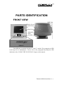
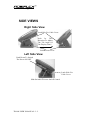
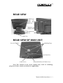
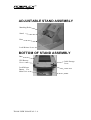
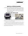
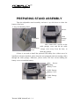
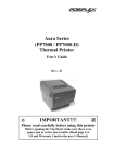
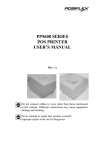
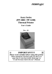
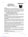
TP-6000 SERIES USER’S MANUAL TOUCH PANEL POS SYSTEM Rev. : A1 SOME IMPORTANT NOTES FCC NOTES This equipment generates, uses, and can radiate radio frequency energy and, if not installed and used in accordance with the instructions manual, may cause interference to radio communications. It has been tested and found to comply with limits for a Class A digital device pursuant to subpart J of Part 15 of FCC Rules, which are designed to provide reasonable protection against interference when operated in a commercial environment. Operation of this equipment in a residential area is likely to cause interference in which case the user at his own expense will be required to take whatever measures to correct the interference. WARRANTY LIMITS Warranty will terminate automatically when the machine is opened by any person other than an authorized technician. The user should consult his/her dealer for the problem happened. Warranty voids if the user does not follow the instructions in application of this merchandise. The manufacturer is by no means responsible for any damage or hazard caused by improper application. ABOUT THIS MANUAL This manual assists the user to utilize the hardware of the TP6000 series that is a member of the POSIFLEX integrated point-of-sale terminal product family. The TP6000 is a compact point-ofsale system that gives the most user friendly human interface by providing touch panel input and combines the performance and affordability of personal computers with the elegance and reliability of business machine. The TP6000 also provides the built-in networking capability for easy communication among multiple terminals in addition to the data transfer and control through back office server. The manufacturer of the TP6000 series heartily apologizes to the user for reserving the right to change or to modify this manual without notice due to the rapid and constant progress and improvement on science and technology. The user may always obtain the most up to date information through our web sites: http://www.posiflex.com.tw, http://www.posiflexuk.com or http://www. posiflexusa.com © Copyright Mustek Corp. 2000 All rights are strictly reserved. No part of this documentation may be reproduced, stored in a retrieval system, or transmitted in any form or by any means, electronic, mechanical, photocopying, or otherwise, without the prior written consent of Mustek Corp. the publisher of this documentation. TRADE MARKS AND SERVICE MARKS POSIFLEX is a registered trademark of Mustek Corp.. Other brand and product names are trademarks and registered trademarks and service marks of their respective owners. CMANUTP6000-2 TABLE OF CONTENTS BRIEF INTRODUCTION . . . . . . . . . . . . . . . . . . . . . . . . . . . . . . . . . . 1 - 1 THE USER’S MANUAL . . . . . . . . . . . . . . . . . . . . . . . . . . . . . . . . 1 THE PRODUCT . . . . . . . . . . . . . . . . . . . . . . . . . . . . . . . . . . . . . . . 1 Overview . . . . . . . . . . . . . . . . . . . . . . . . . . . . . . . . . . . . . . . 1 Configuration . . . . . . . . . . . . . . . . . . . . . . . . . . . . . . . . . . . . 1 Standard Features . . . . . . . . . . . . . . . . . . . . . . . . . . . . . . 1 Optional Items . . . . . . . . . . . . . . . . . . . . . . . . . . . . . . . . 1 - 1 1 1 1 1 3 PARTS IDENTIFICATION . . . . . . . . . . . . . . . . . . . . . . . . . . . . . . . . 2 - 1 FRONT VIEW . . . . . . . . . . . . . . . . . . . . . . . . . . . . . . . . . . . . . . . . . 2 SIDE VIEWS . . . . . . . . . . . . . . . . . . . . . . . . . . . . . . . . . . . . . . . . . . 2 Right Side View . . . . . . . . . . . . . . . . . . . . . . . . . . . . . . . . . 2 Left Side View . . . . . . . . . . . . . . . . . . . . . . . . . . . . . . . . . . . 2 REAR VIEW . . . . . . . . . . . . . . . . . . . . . . . . . . . . . . . . . . . . . . . . . . 2 REAR VIEW OF MAIN UNIT . . . . . . . . . . . . . . . . . . . . . . . . . . . . 2 ADJUSTABLE STAND ASSEMBLY . . . . . . . . . . . . . . . . . . . . . 2 BOTTOM OF STAND ASSEMBLY . . . . . . . . . . . . . . . . . . . . . . 2 - 1 2 2 2 3 3 4 4 INSTALLATION GUIDES . . . . . . . . . . . . . . . . . . . . . . . . . . . . . . . . . 3 - 1 SEPARATING MAIN UNIT . . . . . . . . . . . . . . . . . . . . . . . . . . . . . 3 PREPARING STAND ASSEMBLY . . . . . . . . . . . . . . . . . . . . . . 3 INSTALLING UPS BATTERY . . . . . . . . . . . . . . . . . . . . . . . . . . . 3 ROUTING THE CABLES . . . . . . . . . . . . . . . . . . . . . . . . . . . . . . . 3 PREPARING THE MAIN UNIT . . . . . . . . . . . . . . . . . . . . . . . . . . 3 JOINING MAIN UNIT AND STAND . . . . . . . . . . . . . . . . . . . . . . 3 OPENING CABLE COVER . . . . . . . . . . . . . . . . . . . . . . . . . . . . . 3 CONNECTING CABLES . . . . . . . . . . . . . . . . . . . . . . . . . . . . . . . 3 - 1 2 3 3 4 4 5 6 i INSTALLING CASH DRAWERS . . . . . . . . . . . . . . . . . . . . . . . . 3 - 6 WALL MOUNTING . . . . . . . . . . . . . . . . . . . . . . . . . . . . . . . . . . . . 3 - 7 LOCATION FOR INSTALLATION . . . . . . . . . . . . . . . . . . . . . . . 3 - 7 USING THE TOUCH POS . . . . . . . . . . . . . . . . . . . . . . . . . . . . . . . . 4 - 1 APPLICATION ENVIRONMENT . . . . . . . . . . . . . . . . . . . . . . . . . 4 Ventilation . . . . . . . . . . . . . . . . . . . . . . . . . . . . . . . . . . . . . . 4 Operating Environment . . . . . . . . . . . . . . . . . . . . . . . . . . . 4 Power Supply . . . . . . . . . . . . . . . . . . . . . . . . . . . . . . . . . . . 4 External Monitor . . . . . . . . . . . . . . . . . . . . . . . . . . . . . . . . . 4 Serial Port – COM1 . . . . . . . . . . . . . . . . . . . . . . . . . . . . . . 4 Serial Port – COM2/3/4 . . . . . . . . . . . . . . . . . . . . . . . . . . . 4 POWER ON/OFF . . . . . . . . . . . . . . . . . . . . . . . . . . . . . . . . . . . . . . 4 LED Indicator . . . . . . . . . . . . . . . . . . . . . . . . . . . . . . . . . . . 4 Hardware Switch . . . . . . . . . . . . . . . . . . . . . . . . . . . . . . . . 4 Software Support . . . . . . . . . . . . . . . . . . . . . . . . . . . . . . . . 4 Preset Power On Control . . . . . . . . . . . . . . . . . . . . . . . . . 4 MAGNETIC STRIPE READER . . . . . . . . . . . . . . . . . . . . . . . . . . 4 CASH DRAWER(S) . . . . . . . . . . . . . . . . . . . . . . . . . . . . . . . . . . . . 4 DISPLAY RESOLUTION . . . . . . . . . . . . . . . . . . . . . . . . . . . . . . . 4 SOUND PORT . . . . . . . . . . . . . . . . . . . . . . . . . . . . . . . . . . . . . . . . .4 TOUCH PANEL . . . . . . . . . . . . . . . . . . . . . . . . . . . . . . . . . . . . . . . 4 TOUCH TERMINAL MANAGER . . . . . . . . . . . . . . . . . . . . . . . . . 4 RS232 TOUCH MONITOR MOUSE . . . . . . . . . . . . . . . . . . . . . . 4 ii - 1 1 1 1 1 2 2 2 2 3 4 4 5 5 5 5 6 6 7 BRIEF INTRODUCTION THE USER’S MANUAL The purpose of this manual is to guide the user in the initial installation and general use of the Posiflex fully integrated compact touch terminal system with touch panel input. TP6000 series is a product group of fully integrated PC based touch terminal systems. However, this manual does not intend to explain any application software that may be supplied with the TP6000 systems. The user should consult the software supplier or the VAR that he/she purchased from for such information. The user is encouraged to visit our web site http://www.posiflex.com.tw via the Internet for further information of our products. THE PRODUCT Overview The TP6000 series is one of the most compact yet fully integrated touch terminal systems. This series provides excellent functionality and two choices of enclosure colors, charcoal and beige. Configuration STANDARD FEATURES a) CPU: Celeron or Pentium III on socket 370 per factory setting HDD: 6.4 GB or above b) Support MS DOS, WIN98, WIN NT, WIN 2000 environment c) Power saving support: doze or suspend mode d) High quality 12.1” / 15.1” TFT active matrix LCD panel e) Vertical type LCD panel with easy tilt angle adjustment from 17.5° to 87.5° TP6000 USER’S MANUAL 1 - 1 f) Height adjustment: the high / low adjustment gives 20 mm difference in height g) Resistive type touch panel h) Extra long life touch panel that endures 10 million up to 35 million touches in one location i) Spill proof water resistant structure allows for easy cleaning j) Easy maintenance construction k) Various I/O ports supported, including: 1. 1 PS/2 KB port 2. 1 PS/2 mouse port 3. Serial Ports: 1 for TP6XXXR of system revision A. 2 for TP6XXXP of system revision A. 3 for TP6XXXR of system revision since B. 4 for TP6XXXP of system revision since B. All with capability for +5V DC support 4. 1 parallel port 5. 5 USB ports 6. 1 LAN port 10/100 base T Ethernet 7. 1 Cash drawer port. Allows control over 2 cash drawers with the functionality of open drawer detection 8. 1 MSR connector 9. 1 external FDD port 10. 1 external VGA monitor port 11. 1 UPS battery connector 12. 1 Audio line out port (option) l) m) n) o) Preprogrammed timer wake up function RS232 COM port MODEM ring up function LAN wake up function Built-in UPS function to protect the system from intermittent power failure. (Battery is optional) p) Accidental power off protection – The power switch is safely located at one side, and can be defined as a “ON” only or “ON/OFF” through software commands. TP6000 USER’S MANUAL 1 - 2 q) Touch control functions: left/right mouse buttons, double click, drag & drop r) Touch sound can be pitch adjusted and enabled/disabled by software control s) High resolution touch sensor: 1024 x 1024 t) u) v) w) x) y) DRAM memory can extend to 1GB Dual display support under OS’s supporting multiple display output VGA memory size selectable by software (up to 64 MB) Integrated structure for optional MSR Software selectable MSR parameters 2 color choices: beige or charcoal OPTIONAL ITEMS Note: The factory must install all items underlined in the list below. Posiflex Dealers can install all other items. a) Audio line out port b) UPS battery c) DRAM memory expandable to 1GB d) Integrated ISO 2 or 3 track MSR e) 2 in 1 cash drawer control cable (CCBLA-238) f) Preloaded Windows 98, WIN NT or WIN 2000 g) VFD or LCD stand alone Posiflex pole display h) Wall mount kit i) External FDD TP6000 USER’S MANUAL 1 - 3 TP6000 USER’S MANUAL 1 - 4 PARTS IDENTIFICATION FRONT VIEW MSR Unit Display Screen + Touch Panel Main Unit Adjustable Stand Assembly The MSR unit is optional for both 12” and 15” models. The orange/green LED in the logo area is multipurpose. Please refer to the paragraph discussing the LED indication in the “USING THE TOUCH POS” chapter of this manual. TP6000 USER’S MANUAL 2 - 1 SIDE VIEWS Right Side View Latch Hole For Cable Cover Push In This Direction To Adjust The Tilt Angle Of The Display Panel Lock/Release Lever Left Side View Push Down To Switch The Power ON/OFF Latch Hole For Cable Cover Slide Switch For Power On/Off Control TP6000 USER’S MANUAL 2 - 2 REAR VIEW Lock/Release Button To Detach The Main Unit Optional MSR Unit Lock/Release Lever Cable Exit REAR VIEW OF MAIN UNIT Service Window Matching Pegs Cable Exit Cable Cover Removal Hollow Of Cable Cover Note: The contents in the service window may evolve as technology progresses. Please consult your dealer for applicability. TP6000 USER’S MANUAL 2 - 3 ADJUSTABLE STAND ASSEMBLY Matching Holes Stand Base Lock/Release Lever BOTTOM OF STAND ASSEMBLY Base UPS Battery Cover Lock/Release Button For Main Unit Cable Passage Cover Cable Exit Stand TP6000 USER’S MANUAL 2 - 4 INSTALLATION GUIDES CAUTION: Before installing any cables or peripherals to the terminal, please always make certain that the system is turned off and the external power source is removed to prevent electric hazard! Never touch any pins within the connectors or circuits to avoid high voltage hazard or electrostatic discharge. Failure to follow this caution may cause damage to the unit. SEPARATING MAIN UNIT Press the Lock/Release button and slide the stand assembly to the panel downward side to detach it from the main unit. In order to properly install the TP-6000 terminal, all cables must be routed through its base. Therefore, please press the lock/release button at the rear side to separate the main unit from the stand assembly. However, in view of the mass distribution of the whole assembly, it is most recommended to lay the system facing down on front panel over a soft clean flat surface first. Press the button and slide the stand assembly to the panel downward side to detach the stand assembly away from the back of the main unit could then be an easier operation. This approach can also be applied when later on the main unit and the stand assembly have to be reunited. TP6000 USER’S MANUAL 3 - 1 PREPARING STAND ASSEMBLY Take the adjustable stand assembly and turn it up side down to show the bottom of the base. 2 Sets of 4 Matching Holes Screws Cable Passage Cover Adjustable Stand Now, remove the 2 screws on the cable passage cover and lift the cable Lock/Release passage cover away from the base, to Lever show the passage. If there is no need to install the optional UPS battery here (either not to be installed or already installed), please skip the next paragraph and start routing cables through the cable passage. Otherwise, please remove the four screws holding the battery cover to install the battery. Four Screws Holding Battery Cover Cable Passage Battery Cover Cable Passage Cover TP6000 USER’S MANUAL 3 - 2 INSTALLING UPS BATTERY UPS Battery Removed Battery Cover Place the optional UPS battery in the battery compartment (shown top left). Screw on the battery cover and route the battery cable through the base. Please enable the UPS features in the software settings before use. ROUTING THE CABLES Place all required cables into the cable passage. Insert one end of the cable passage cover under the battery cover and replace the two screws. Be sure not to damage any of the cables during this operation. Now, turn the adjustable stand assembly back to normal orientation and arrange all cables so that they will be easily connected after the terminal is mounted to the base. TP6000 USER’S MANUAL 3 - 3 PREPARING THE MAIN UNIT On the back of the main unit, there are 4 matching pegs and a service window. Push the service window open, in the direction indicated in the picture. Below, one can find a button cell battery socket, a 1 x 3 header (JP10) with 1 jumper and a 2 x 3 header (JP8) with 2 jumpers. Service Window 4 Matching Pegs Push Open To The Right This battery socket requires a 3V button cell Lithium battery (CR2032) to support the system clock. The jumpers in this window are designated for COM port power supply and UPS battery detect functions. Please contact your dealer for technical support on setup of these jumpers. A new Lithium battery can support the system RTC for about 3 years. After the battery is nearly exhausted, the user must replace the battery otherwise the system RTC and system configuration setup will be lost. JOINING MAIN UNIT AND STAND Matching Pegs Matching Holes Round Part Slot Part Removal Hollow Align the matching pegs on the back of the main unit against one of the two sets of matching holes on the stand base. It is recommended that the terminal be hooked onto the lower set of holes for better stability. First aim the matching pegs TP6000 USER’S MANUAL 3 - 4 toward the upper round part of the hole and make sure that all pegs have been properly seated. Then slide the main unit down to move the pegs into the narrow section of the slot until the rear latch clicks. Note that all the cables come out of the stand from the lower edge and won’t get trapped by this mounting operation. If later on you want to remove the main unit from the stand, you’ll have to press down the lock/release button on back of the stand when lifting the main unit. OPENING CABLE COVER Insert the tip of the latchkey into a latch hole on one side near bottom of the main unit. Turn this key counterclockwise to the end. Do the same on the opposite side. Be sure to take the key out of the hole. Turn Counterclockwise Then Take Out The Latchkey Then push the lock/release lever on the base backward to adjust the stand to the most horizontal position for ease of operation. Open the cable cover by pulling at the removal hole. Pull The Removal Hole Away from the machine. TP6000 USER’S MANUAL 3 - 5 CONNECTING CABLES Connect the required cables to the appropriate connectors. Please make sure that each connector is connected to the right port with the correct orientation. Some connectors, such as the LAN connector, the external FDD connector, the power connector, the cash drawer connector, and the COM4 connector for the conversion cable have to be inserted until a click is heard. It is recommended that connectors such as the external VGA connector, the LPT port connector and the COM port connectors, be screwed into place once seated. If the COM1 port must be used, the COM1 terminator that occupies the COM1 port must be removed. However, when using the COM1 port, be sure to use devices that provide proper handshaking signals in order to keep the cash drawer control features. A serial mouse is one example of a device that does not support handshaking. Adjust the slack of each cable and close the cable cover. Use the same plastic latch key that is used when removing the cable cover, but be sure to turn it in the clockwise direction to lock the cover in place. Re-adjust the tilt angle of the screen for best viewing. CAUTION: Before inserting or extracting the power plug, be sure to pull the outer sleeve of the plug away from the machine to release the internal latch. Failure to do this could damage the power connector. Such damage is considered to be user error, and will not be covered by the warranty. INSTALLING CASH DRAWERS When there is only one cash drawer installed, connect the standard cable CCBLA-180 or CCBLA-180-1 that comes with the cash drawer to the RJ11C jack next to the PS2 KB connector (be careful not to connect this cable to the Modem connector or the COM4 connector on the left). When there are two cash drawers being installed, please purchase and use the optional cash drawer control splitter cable CCBLA-238. The CCBLA-238 has a 6 pin male connector at one end and two 8 pin male connectors at the other. The 6 pin connector should be inserted in the connector marked “CR”, found on the cabling panel of the TP6000 series. Each 8 pin connector should be inserted into the connector TP6000 USER’S MANUAL 3 - 6 marked “signal cable from POS Printer” at the rear of each cash drawer. The cable lengths for the two 8 pin plugs are different. Use the shorter one for the first cash drawer “CR1” and use the longer one for the second cash drawer “CR2” that will be controlled by the application software. Using this method, the TP6000 is capable of controlling two cash drawers independently through software command. WALL MOUNTING The main part in the wall mounting kit is a bracket as shown in the picture. When mounting the TP-6000 bracket to a wall, be sure that the widest part of each of the four holes faces in the upward direction (see picture below). Align the four matching pegs on the back of the main unit to the four matching holes in the bracket to hold the main unit in a similar manner as installing the main unit onto the stand assembly. The stand assembly is not used with a wall mount installation. Matching Holes Wall Mount Bracket Screw At Screw Holes Through Matching Holes LOCATION FOR INSTALLATION Since the stand assembly is not involved in wall mount installation, only the space required for wall mount application will be taken into consideration. The space required is 375 mm in width and 315 mm in height. For desk top/counter applications, the adjustable stand assembly requires a base 270 mm deep and 260 mm wide. However, please take the main unit into consideration. If the main unit is tilted to the near vertical position, the total height can TP6000 USER’S MANUAL 3 - 7 be either 360 mm or 380 mm depending on the adjusted position. When the main unit is tilted to near horizontal position, the total height required is 275 mm. TP6000 USER’S MANUAL 3 - 8 USING THE TOUCH POS APPLICATION ENVIRONMENT It is very important that you check the following operational guidelines: Ventilation This terminal must NOT be operated in an environment with restricted ventilation. The installation should be such that there is at least 25mm air clearance around any top or side ventilation holes. The installation must also be such that there is a free flow of air around the unit at ALL times. Operating Environment The equipment must not be operated or stored in extreme temperature or humidity/moisture. (Operating range is 5°C to 40°C and up to 80% humidity – no condensation) Power Supply The operating voltage range of proper operation should be noted on the power adaptor. The power cable, the power outlet, and any power fusing arrangements must conform to local safety regulations. External Monitor The external VGA port in the TP6000 series supports any regular VGA monitor using a separate AC power source and a resolution of 1024 x 768 with true color. Unlike other Posiflex POS terminals, the DC powered 9” VGA mono monitor is not supported by this series. Please refer to the information for the OS for its “mirror” or “extended” dual display applications. TP6000 USER’S MANUAL 4 - 1 Serial Port – COM1 CAUTION: The COM1 serial port should be occupied by either a suitable serial device or a COM1 terminator at all times (as supplied). Without this provision the cash drawer control ports will fail to work correctly. The recommended devices for COM1 are either an external customer display or a serial POS printer. When such devices are installed to the TP6000 series, please remove the COM1 terminator and store in a safe place for future use. Serial Port – COM2/3/4 For models using the RS232 interface touch controller (TP6XXXR), there is no extra serial port other than COM1 available for system revision A and for models of system revision B or later COM4 port is not available. For models of system revision A using the PS2 interface touch controller (TP6XXXP), only COM1 and COM2 are available. The COM4 has to be connected through a special cable CCBLA-338. All these ports are standard RS232 serial port with the possibility to supply a +5 V DC through pin 9 after proper jumper setting change. Any attempt to break/remove the cover/plug on the forbidden port (COM2 of rev. A or COM4 of rev. B or later) in TP6XXXR will void the product warranty. POWER ON/OFF LED Indicator Ÿ Ÿ There is an LED in the logo area that serves several purposes. When the TP6000 is standing by for power up in the presence of external power supply, the LED is orange. When the TP6000 is powered up and working normally with the external power supply, the LED is green. TP6000 USER’S MANUAL 4 - 2 Ÿ When the external power fails and the TP6000 is working on the optional UPS battery power, the green LED flashes. Ÿ When the optional UPS battery is close to full discharge from supporting the TP6000 in the absence of the external power, the orange LED flashes rapidly. Ÿ When the TP6000 is turned off and the external power is not present, the LED is off. This system will not allow power up in the absence of an external power supply. The maximum total power consumption of the external power supply unit is 1.6 A at 115 V AC or 0.8 A at 230 V AC. Hardware Switch The power switch located at left side of the main unit is a slide type switch. This switch controls the power on/off of the system. This switch turns the system on when slid downward, only when external power is present. The switch will always spring back to its original position when pressure is removed. This switch turns the system off when slid downward again during power on status. However, if the system hangs due to any reason such as software resource conflict a simple slide of the switch may fail to turn off the power. In this case, please utilize the forced power off feature by pressing the switch downward, and holding for within 10 seconds. In case the turmoil is so vigorous that some hardware registers may be confused causing trouble for system restart or even this forced power off, please disconnect the UPS battery if installed and the AC power supply for few minutes. This may allow all hardware registers to reset. This switch can also be programmed as an ON only switch. That means, if the application program issues a command compliant with the TP6000 series technical manual, this switch will always turn the system on when activated, but will not power off the system when depressed again (the forced power off feature will not work in this mode). When using this feature, please make sure that the software application has the ability to power off the machine. TP6000 USER’S MANUAL 4 - 3 Software Support The TP6000 series provides a software power off command for application program maneuvers. The TP6000 also provides a specific means for the software to detect if the system is working on external or UPS battery power. Due to this feature, compatible software applications have the ability to change operating conditions when running on standard/backup power. The software programmer may take reference from the TP6000 technical manual to apply such features. Preset Power On Control The system may also be turned on according to predetermined parameters, such as Modem Ring Up, Alarm Clock Wake Up and/or Wake-on-LAN. To utilize these functions, the user should enter the CMOS setup by pressing the “DEL” key at system boot up and choose the “INTEGRATED PERIPHERALS” option. Next, set the “Ring Power Up Control” to enable for Modem Ring Up or select the “Power Up by Alarm” for Alarm Clock Wake Up. Save the configuration and exit the CMOS setup program. The Preset Power On Control will then be activated. However, for the Wake-on-LAN feature, certain specific programs have to be executed prior to power off. This program will set the terminal to standby for LAN Wake Up during power off so that when the predefined condition is met (LAN status changes or receives a certain packet) the TP6000 will then be powered on. When the TP6000 system is turned off after a successful boot up, the defined preset power on functions will keep monitoring for the preset conditions. When a Modem call or Wake-on-LAN Packet is received, the system will be turned on and start to work according to the security conditions that the application program defines, only if the Ring Power Up Control or LAN Wake Up function is enabled. If the Power Up by Alarm is enabled, the TP6000 system will be turned on at the defined time (Hour : Minute : Second) of the preset day of week, day of month, month of year or even every day if the date items are not defined. Please note that if the TP6000 system is improperly turned off before a complete boot up process, the above preset power on control functions will be disabled until completion of the next successful boot process. TP6000 USER’S MANUAL 4 - 4 MAGNETIC STRIPE READER The magnetic stripe reader, if installed, will be mounted on the right edge of the TP6000 series. When reading an ISO standard magnetic card, please face the magnetic stripe toward the TP6000 series and slide the card downward through the slot. CASH DRAWER(S) The cash drawer control port, if connected to a Posiflex cash drawer, not only provides a way to open the cash drawer through software commands, but also provides a detection method for the software to check the drawer open status for consequent security measures. The TP6000 series provides one cash drawer connector with the ability to control two cash drawers. When using the standard CCBLA-180 (or CCBLA-180-1) cash drawer cable, the TP6000 has the ability to control one cash drawer. When the optional CCBLA-238 cable is connected to the CR1 port, this gives the TP6000 the ability to control two cash drawers independently. Note: Both cables, CCBLA-180 (or CCBLA-180-1) and CCBLA-238 are designed for use with Cash Drawer models CR3100 or CR3200 or CR4000 or CR4100 only. DISPLAY RESOLUTION For best viewing results, please set the TP6X12 display resolution at 800 x 600 with true color in the operating system. For the TP6X15, please set the display resolution at 1024 x 768 with high color. Of course, other resolution as set through the Windows can still obtain a full size display. SOUND PORT The optional audio port supports stereo line out. Therefore please connect to a booster speaker if used. TP6000 USER’S MANUAL 4 - 5 TOUCH PANEL The touch panel in TP6000 series uses either a PS2 interface or an RS232 interfaced. When its driver is properly installed, this touch panel works exactly like a standard mouse. However, if the system is running under safe mode due to a previous improper shutdown or for any other reason, most drivers are disabled in this mode and the touch panel calibration may not coincide with the mouse pointer. It is recommended that a standard PS2 mouse or keyboard be used in this mode. All the below mentioned mouse emulation functions can be manipulated through relevant software. The system can give a beep when the touch panel is touched and can respond as if the left button of a PS2 mouse is clicked at the point touched. If the point touched is dragged across the screen surface, it can respond as though it is using the mouse drag and drop feature. If the point is touched, released and touched within a short time interval, it will simulate double-clicking the mouse. For the standard PS2 interface touch panel controller, touching the screen for a while followed by a slight move of the touch without leaving the screen surface will result in a right button mouse click. For the RS232 interface touch panel controller, touching any point on the screen surface after touching the right-click sticky button results as a click on the right button of the mouse at that point. However, the right button function is not applicable under the WIN NT environment. TOUCH TERMINAL MANAGER The touch panel control parameters are already well calibrated in the factory prior to delivery. In principal, the touch panel requires no further calibration once properly set. However, a program named “Posiflex Touch Terminal Manager” is installed in the preloaded Windows system for the user to maneuver versatile features of the touch terminal with a PS2 interface touch panel controller. This program can also be obtained by download from the POSIFLEX web site. This program application provides control over the MSR, the touch panel and the power control of the Posiflex Touch Terminal. For an RS232 interface touch panel, the touch panel portion of the following section should be disregarded. Please refer to the paragraph titled “RS232 TOUCH MONITOR MOUSE” instead. TP6000 USER’S MANUAL 4 - 6 This program controls software gating of data read from each MSR track and the way that the data is sent from the reader to the system, including the coding method against language systems, data transmission speed, delivery and selection on the leading/ending code of each track. This program also controls the beep generated when the touch panel is touched, the detail in right button click emulation, and also provides touch panel recalibration. This program can also be used to define the power switch to be on only or on/off, the delay time before software power off and whether a UPS battery is activated in the power control system. RS232 TOUCH MONITOR MOUSE If the product model purchased is TP6XXXR, the touch panel uses an RS232 interface controller. The “Touch Panel Manager” of the above “Posiflex Touch Terminal Manager” should be disregarded and a separate software called Monitor Mouse should be used. In these models, the COM2 connector on system revision A or the COM4 connector (in form of RJ45 jack) on system revision since B will be either covered or plugged to prohibit any use of this port other than the connected RS232 touch controller. Removal of this cover/plug will void the product warranty!! In principle, the driver is installed with the systems equipped with the RS232 touch controller. However, if a re-installation is required, please select “SmartSet Serial Controller on COM2” for system revision A or “SmartSet Serial controller on COM4” for system revision since B as the controller type during the installation process. Once the RS232 touch controller driver is installed, the user can utilize it to calibrate the touch screen, define mouse button emulation modes, enable right button emulation or define the click sound’s tone and duration. Please click “Start”, “Setting”, “Control Panel” and “Elo Touchscreen” to engage this utility. However, with this touch controller driver, certain display mode like full screen display of Windows DOS box should be avoided. If, for any reason, the user wants to remove the driver for the RS232 touch controller, please select “Monitor Mouse for Windows 95” in the program list for removal. TP6000 USER’S MANUAL 4 - 7