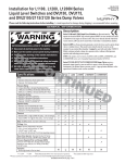
1
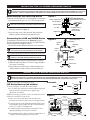
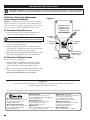
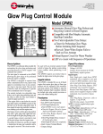
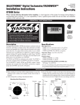
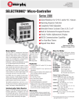
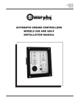
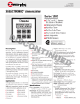
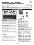
LLS, LLSB, LLSR, LLSRB Series Models
Lead Line Pressure Switches
Installation and Operation Instructions
LLS-93096N
Effective 03-94
Section 05
®
FRANK W.
MFR.
Please read the following information before installing. A visual inspection of this product for damage during shipping is recommended before mounting.
It is your responsibility to have a qualified person install the unit and make sure installation conforms to NEC and local codes.
GENERAL INFORMATION
WARNING
BEFORE BEGINNING INSTALLATION OF THIS MURPHY PRODUCT
✔
✔
✔
✔
Disconnect all electrical power to the machine.
Make sure the machine cannot operate during installation.
Follow all safety warnings of the machine manufacturer.
Read and follow all installation instructions.
LLS Series Pressure Switch
Description
• Sensor Body: LLS: CRS steel chromate plated; 2 in. NPT connection.
The LLS Series is a pressure switch for applications where viscous liquids
could plug the sensing orifice. LLS and LLSB models have a 2 inch NPT
male connection which attaches directly into the process line. LLSR and
LLSRB models feature a remote sensor connected to the pressure switch by a
length of stainless steel capillary and armor. The snap-acting switch is field
adjustable. The switch is housed in a hard anodized aluminum enclosure.
Optional for LLSR and LLSRB models is a 1 inch NPT x 1 inch NPT (male)
pulsation dampener to minimize damaging pressure pulsation to the switch.
LLSB: Thick wall 304 stainless steel sensor 2 in. NPT process connection.
LLSR: Remote Sensor; Nickel plated steel, stainless steel capillary.
LLSRB: Remote Sensor; 316 stainless steel housing and capillary.
• Diaphragm Materials:
LLS/LLSB: Ni-SPAN®. LLSR/LLSRB: 316L S. Steel–Teflon* coated.
• Snap-switch Ratings: SPDT (Std.): 15 A @ 125, 250 or 480 VAC
SPDT (Gold): 100 mA @ 125 VAC; 0.250 A @ 6 VDC
DPDT (Std.): 11 A @ 125 or 250 VAC
DPDT (Gold): 100 mA @ 125 VAC; 0.250 A @ 6 VDC
• Trip Point Adjustment: Field-adjusted with screwdriver.
• LLSR/LLSRB Mount: 4-hole bolt pattern; 1/4 in. (6 mm) dia. bolts.
• LLS/LLSB Mount: Direct mount into process (2 in. NPT connection).
Specifications
• Maximum Ambient Temperature: -10° to +160°F (-23° to +71°C).
• Maximum Process Temperature: -40° to +160°F (-40° to +71°C).
• Temperature Compensation: The volumetric expansion and contraction of
the fill may cause a shift of ±3% to ±5% of the set point.
• Switch Enclosure: Aluminum hard anodized (black). NEMA 4, 4x. NEMA 7
and 9 explosion-proof, waterproof and corrosion resistant. Suitable for Class I,
Div. 1, Groups A, B, C, D; Class II, Div. 2, Groups E, F, G.
• Shipping Weight: LLS/LLSB: 4 lbs. 9 oz. (2.25 kg).
LLSR/LLSRB: 7 lbs. 12 oz. (3.23 kg).
• Shipping Dimensions: LLS/LLSB: 10 x 9-1/4 x 5-3/4 in. (254 x 235 x 146 mm).
LLSR/LLSRB: 15-3/4 x 11 x 5-1/4 in. (400 x 279 x 133 mm).
Sensor Model Selection Table
Base
Model
LLS
LLSB
LLSR
LLSRB
Switch Adjustment Range
psi
kPa/MPa
50–450
345 kPa–3.1 MPa
100–1750 689 kPa–12 MPa
200–2500 13.8 MPa–17.2 MPa
400–4000 2.8 MPa–27.5 MPa
50–450
345 kPa–3.1 MPa
100–1750 689 kPa–12 MPa
200–2500 13.8 MPa–17.2 MPa
400–4000 2.8 MPa–27.5 MPa
50–450
345 kPa–3.1 MPa
100–1750 689 kPa–12 MPa
200–2500 13.8 MPa–17.2 MPa
50–450
345 kPa–3.1 MPa
100–1750 689 kPa–12 MPa
200–2500 13.8 MPa–17.2 MPa
400–4000 2.8 MPa–27.5 MPa
Dead Band Approximate
psi
kPa/MPa
5–45
34 kPa–310 kPa
15–100 103 kPa–689 kPa
20–150 137 kPa–1.03 MPa
75–450 517 kPa–3.1 MPa
5–45
34 kPa–310 kPa
15–100 103 kPa–689 kPa
20–150 137 kPa–1.03 MPa
75–450 517 kPa–3.1 MPa
5–45
34 kPa–310 kPa
15–100 103 kPa–689 kPa
20–100 137 kPa–689 kPa
5–45
34 kPa–310 kPa
15–100 103 kPa–689 kPa
20–150 137 kPa–1.03 MPa
75–450 517 kPa–3.1 MPa
Max System
psi
MPa
1500
10.3
2500
17.2
3000
20.6
5000
34.4
1500
10.3
2500
17.2
3000
20.6
5000
34.4
1500
10.3
2500
17.2
3000
20.6
1500
10.3
2500
17.2
5000
34.4
5000
34.4
Wetted Parts Materials
CRS steel sensor –chromate plated (yellow)
Ni-SPAN® diaphragm.
Thick wall 304 stainless steel sensor housing;
Ni-SPAN® diaphragm. Meets NACE MR-01-75
standard for direct exposure to H2S.
Remote sensor–Nickel plated steel w/ stainless
steel capillary; Teflon* coated diaphragm.
Remote sensor–AISI 316 stainless steel housing;
stainless steel capillary and armor; AISI 316L
stainless steel Teflon* coated diaphragm.
* Teflon–DuPont Trademark
1
DIMENSIONS
LLS and LLSB Models
Complete Unit
Front View
Switch Enclosure
Top View
3 in.
(76 mm)
Switch
Enclosure
9-1/4 in.
(235 mm)
MAX.
Switch
Trip Point
Adjustment
Panel
2-9/64 in.
(54 mm)
7/8 in.
(22 mm)
1-1/2 in.
(38 mm)
3/4-14 NPT
Conduit Inlet
Sensor Enclosure
End View
Do NOT Tamper with
these Sealed
Connections
Sensor
Body
2-1/2 in.
(64 mm)
MAX.
2 in. NPT
Process
Connection
Diaphragm
LLSR and LLSRB Models
Sensor Enclosure
Front View
Switch Enclosure
Front View
Transmitting tube
6-1/2 in.
(165 mm)
MAX.
LLSR models:
3-3/4 in. (95 mm) dia.
LLSRB models:
3-7/8 in. (98 mm) dia.
Switch
Enclosure
Switch
Trip Point
Adjustment
Panel
Sensor
Body
2-7/8 in.
(73 mm)
1-13/16 in.
(46 mm)
3/4 in.
(19 mm)
1 in. NPT (female) Connection
17/64 x 1/2 in.
(7 x 13 mm)
mounting holes
(4 places)
Pulsation Dampener
PD8187 Option
2-1/2 in.
(64 mm)
Do NOT Tamper with
these Sealed
Connections
2
Transmitting
tube, 5 feet
(1.524 m) std.
3-7/8 in.
(98 mm)
FLOW
3-1/2 in.
(89 mm)
1 in. NPT (male)
Process Connection
2 places
INSTALLING THE LLS SERIES PRESSURE SWITCH
WARNING: PERFORM THE INSTALLATION WITH POWER SOURCE “OFF”. NEVER EXCEED RATED PRESSURE RANGE FOR THE UNIT.
USE WRENCH ON SHANK TO TIGHTEN/LOOSEN CONNECTIONS. DO NOT TWIST THE ENCLOSURE WHEN SCREWING THE LLS INTO THE
PROCESS – THIS WILL DAMAGE INTERNAL COMPONENTS, FILLED MECHANISM AND THE SEALS. DO NOT OVERTIGHTEN THE UNIT.
Connecting the LLS and LLSB Series
To install the LLS and LLSB Series, a vertical mounting is recommended.
1. The unit threads directly into a 2 in. 11-1/2 NPT tee on the lead line.
CAUTION: DO NOT TAMPER WITH OR BREAK SEALED CONNECTIONS. APPLY PIPE SEALANT TO PROCESS CONNECTION THREADS.
Figure 1
Do NOT Tamper with
these Sealed Connections
Do NOT Tamper with
This Connection
Wrench Flats
Use Wrech Flats to
Screw the LLS
Into the Process
2 in. NPT
2. Tighten the bottom housing to the lead line tee using ONLY the
transmitter wrench flats (see figure 1).
Lead line tee
3. Check for leakage on any of the connections. Make sure that the
installation conforms with local and other applicable codes.
Connecting the LLSR and LLSRB Series
For mounting the switch enclosure refer to “Dimensions” on page 2.
The following instructions are based on the usage of a PD8187 Pulsation
Dampener option shown in Figure 2 (at right.)
1. Install sensor/pulsation dampener into pressure source connection.
Figure 2
Transmitting Tubing
(capillary)
Housing
Bolts
CAUTION: THE PD8187 PULSATION DAMPENER IS NOT INTENDED
Diaphragm
Body
Wrench
Flats
AS A SHUTOFF VALVE. APPLY PIPE SEALANT TO THE THREADS.
2. Loosen the eight housing bolts until the bottom housing is free to turn.
CAUTION: WHEN LOOSING THE EIGHT HOUSING BOLTS, MAKE
Pulsation
Dampener
(optional)
SURE NOT TO UNSCREW THE GREEN DIAPHRAGM CAPSULE.
3. Tighten the bottom housing to the pulsation dampener connection.
4. Tighten the eight housing bolts to 25±3 foot lbs. Stagger the tightening to assure even clamping.
5. Route capillary away from heat source (exhaust manifold). Excess
capillary should be carefully coiled and secured (do NOT cut it).
1 in. NPT
Lead Line Tee
WIRING THE LLS SERIES PRESSURE SWITCH
WARNING: PERFORM THE WIRING OPERATION WITH THE POWER SOURCE “OFF”. MAKE SURE VOLTAGE AND CURRENT REQUIREMENTS ARE WITHIN THE LLS RATINGS. BEFORE WIRING THE UNIT DETERMINE VOLTAGE AND POLARITY FOR THE APPLICATION.
IF THE UNIT IS USED IN HAZARDOUS AREAS, MAKE THE AREA SAFE BEFORE REMOVING THE SNAP-SWITCH(ES) COVER.
If switch trip point needs to be adjusted, see page 4.
LLS Series Hook-up (all models)
To wire the LLS Series, use proper the electrical conduit.
1. A 3/4''-14 NPT inlet connection for conduit installation is provided
at the top end of the switch enclosure (see opposite page–
“Dimensions” for location).
NOTE: The plastic plug (supplied) is to protect the conduit inlet threads
and must be removed before wiring the unit.
2. Using a 3/16 in. hex wrench, unscrew the 4 hex-cap screws.
Now proceed to remove the square cover to reveal snap-switch(es).
3. To wire the unit, refer to the typical wiring drawing (Figure 3) and
to the Schematic (shown at right). Wire the LLS Series switch(es)
with 60°/75°C (140°/167°F) insulated wire.
4. A terminal (inside the switch enclosure) is provided for case or
equipment grounding, refer to Figure 3 for location.
5. After completing wiring, replace the switch cover and make sure it
is tightly secured before applying power to the system.
P
P
Schematic
NC
NC
SPDT
DPDT
C
NO
C
NO
NC
C
NO
Figure 3
Customer
Wiring
SPDT
DPDT
3/4 in.-14 NPT
Conduit Inlet
N.O.
N.C.
COM.
Provision for
Case Ground
NC NO C
NC NO C
Terminal
Block(s)
3
ADJUSTING THE TRIP POINT
CAUTION: REMEMBER THAT THE FIELD-ADJUSTABLE TRIP POINT MAY HAVE BEEN FACTORY SET TO YOUR SPECIFICATIONS.
ADJUSTMENT OF THE TRIP POINT VARIES ACCORDINGLY TO THE APPLICATION AND MUST BE PERFORMED BY A QUALIFIED PERSON.
LLS Series Trip Point Adjustment
if necessary (all models)
Figure 4
NOTICE: If trip point is not specified, the switch will be set at approximately 50% of full scale. To perform trip point re-adjustments, a test
stand with variable pressure source, a test light, and a pressure gauge
(such as our OPLG or OPLFG MURPHYGAGE®) may be used.
Snap-switch(es) Cover
or Square Cover
Do NOT remove until
the area is made
NON-HAZARDOUS
To Reset for Rising Pressure
1. Locate and remove the Switch Trip Point Adjustment cover
(round) to reveal the Adjustment Wheel, (see figure 4).
WARNING: DO NOT REMOVE SNAP-SWITCH COVER AT THE
Screwdriver
Adjustment
Wheel
INSTALLATION SIGHT UNTIL THE AREA IS MADE NON-HAZARDOUS.
2. After area is made non-hazardous, proceed to remove the square
cover to reveal the snap-switch(es).
3. Connect test light to (COM) and (N.C.) terminals. The light
should turn “ON”. Gradually increase the pressure until the light
turns“OFF”. Observe the trip point pressure reading.
4. With a screwdriver, turn the adjustment wheel to the desired setting.
Repeat step 4 until the light turns “OFF” at the desired pressure.
To increase
set point
To decrease
set point
Switch Trip Point
Adjustment Cover
or Round Cover
To Reset for Falling Pressure
Follow step 1 and step 2 (above), then:
3. Connect test light to (COM) and (N.O.) terminals. The light
should stay “OFF”. Gradually increase the pressure until the
light turns“ON”. Observe the trip point pressure reading.
4. With a screwdriver, turn the adjustment wheel to the desired setting.
Repeat step 4 until the light turns “OFF” at the desired pressure.
Replace the adjustment and the switch covers securely.
WARRANTY
A two year limited warranty on materials and workmanship is provided with this Murphy product. Details are
available on request and are packed with each unit.
In order to consistently bring you the highest quality, full featured products, we reserve the right to change our specifications and designs at any time.
®
FRANK W.
Since 1939
MFR.
■ Frank W. Murphy Manufacturer
P.O. Box 470248; Tulsa, Oklahoma 74147; USA
tel. (918) 627-3550 fax (918) 664-6146
e-mail [email protected]
■ Frank W. Murphy Southern Division
P.O. Box 1819; Rosenberg, Texas 77471; USA
tel. (281) 342-0297 fax (281) 341-6006
e-mail [email protected]
Printed in U.S.A.
4
■ Frank W. Murphy, Ltd.
Church Rd.; Laverstock, Salisbury SP1 1QZ; U.K.
tel. +44 1722 410055 fax +44 1722 410088 tlx 477088
e-mail [email protected]
■ Frank W. Murphy Pte., Ltd.
26 Siglap Drive; Republic of Singapore 456153
tel. +65 241-3166 fax +65 241-8382
e-mail [email protected]
■ Murphek Pty., Ltd.
1620 Hume Highway; Campbellfield, Vic 3061; Australia
tel. +61 3 9358-5555 fax +61 3 9358-5558
■ Murphy de México, S.A. de C.V.
Blvd. Antonio Rocha Cordero 300, Fracción del Aguaje
San Luis Potosí, S.L.P.; México 78384
tel. +52-48-206264 fax +52-48-206336
e-mail [email protected]
■ Murphy Switch of California
P.O. Box 900788; Palmdale, California 93590; USA
tel. (805) 272-4700 fax (805) 947-7570
e-mail [email protected]
■ Frank W. Murphy France
tel. +33 1 30 762626 fax +33 1 30 763989