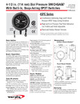
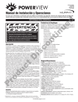
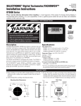
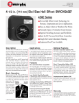
1
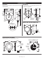
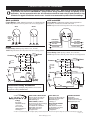
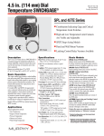
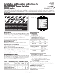
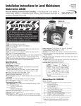
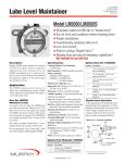
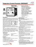
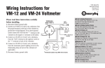
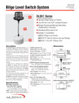
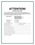
SPL-92106N
Revised 04-04
Section 10
Installation for 4-1/2 in. (114 mm) dial
Temperature MURPHYGAGE® and SWICHGAGE®
(00-02-0167)
Model Series: SPLG, SPLC, SPLBP, 45TE and 45TEBP
Options: -OS and -ES
Please read the following instructions before installing. A visual inspection is recommended before mounting.
General Information and these installation instructions are intended for all 4-1/2 in. (114 mm) dial temperature models.
GENERAL INFORMATION
*
WARNING
®
**
BEFORE BEGINNING INSTALLATION OF THIS MURPHY PRODUCT
✔
✔
✔
✔
Disconnect all electrical power to the machine.
Make sure the machine cannot operate during installation.
Follow all safety warnings of the machine manufacturer.
Read and follow all installation instructions.
SPLC and SPLFC SWICHGAGE® instruments have high
and low limit contacts to monitor, alarm or shutdown. The SPLC
has a flanged case. SPLFC has a flush mount case intended for
installation within a panel. A method to override the low limit
contact for startup is provided on most models (see Operation
Test Instructions on page 3).
45TE and 45TEF Series are versions of the SPL Series
with 2-snap acting SPDT switches instead of the pointer type contacts. The 45TE Series does not include low contact lockout.
SPLBP and 45TEBP models are designed to start and stop
electric motor driven equipment. The pilot duty contacts are connected to a latching control relay for automatic ON/OFF control,
either directly or through a motor starter.
Options -OS and -ES
The -OS (oil sealed case) and the -ES (environment sealed case)
options for corrosive environment feature flush mount case design
to be installed within a panel.
Precautions
■
■
■
■
■
■
Do NOT exceed rated temperature range.
Use shock mounts as necessary to protect from vibration.
Cutting or sharp bending the capillary will cause permanent
damage to the SWICHGAGE® and will void the warranty.
Excess capillary should be carefully coiled and secured
away from damage.
Do not route capillary along exhaust manifold.
Avoid routing capillary at level higher than gage mounting.
Specifications
Dial: White on black, dual scale, °F and °C standard,
4-1/2 in. (114 mm) diameter.
Case: Die cast aluminum, surface or panel mount.
Capillary: PVC armored copper tube, 5 ft. (1.5 m) long standard.
Sensing Bulb: Copper bulb std.: 1/2 in. (13 mm) OD;
Length 7 in. (178 mm). Pressure rating: 600 psi (4.1 MPa)
[41 bar]. Connection: 1/2 NPTM compression fitting.
NOTE: Use of thermowell is highly recommended.
Switch Reset Deadband: Approximately 10% FS.
Snap-Acting Switches: See wiring information (page 4).
Dry Relay Contact (“BP” Models): 10 A @ 28 VDC or
10 A @ 120 VAC.
Wire Connections (Surface Mount): 1/2 NPTF conduit/terminal block.
Wire Connections (Panel Mount): Wire leads, 18 AWG
(1.0 mm2) x 9 in. (229 mm) long.
Wire Connections (-ES, -OS, -CC): 1/2 NPTM conduit and wire leads,
24 AWG (0.22 mm2) x 33 in. (838 mm) long.
Overrange: Do not exceed 10% FS above full range.
Item Weight: 8 lbs (3.6 kg) approx. Explosion-proof models: 22 lb.
(10 kg) approx.
Item Dimensions: 16 x 11 x 5-1/2 in. (406 x 279 x 140 mm)
approximately. Explosion-proof: 12 x 12 x 9 in. (305 x 305 x 229 mm)
approximately.
Accuracy
Lower 1/4
Middle 1/2
Upper 1/4
15 to 250°F
(9 to 121°C)
± 8°F
(± 4°C)
± 2°F
(± 1°C)
± 2°F
(± 1°C)
130 to 350°F
(54 to 177°C)
260 to 450°F
(127 to 232°C)
± 8°F
(± 4°C)
± 8°F
(± 4°C)
± 2°F
(± 1°C)
± 2°F
(± 1°C)
± 3°F
(± 1.5°C)
± 3°F
(± 1.5°C)
Temperature Range
*Selected configurations are CSA approved. Consult factory for details.
**Products covered by this literature comply with EMC Council directive 89/336/EEC
regarding electromagnetic compatibility as noted. Does not cover “BP” models.
SPL-92106N page 1 of 4
CASE MOUNTING
Wall Mount
Flanged case design intended for wall mount. Shown with shock
mounts (optional).
Flush Mount
A round case design to be mounted within a panel from 1/32 in.
(1 mm) to 1/8 in. (3 mm) thick.
5-7/16 in.
(138 mm)
8-7/16 in.
(214 mm)
3-3/8 in.
(86 mm)
7-7/8 in.
(200 mm)
4-1/32in.
(102 mm)
2-57/64 in.
(73 mm)
3-15/16 in.
(100 mm)
1/2 in.
(13 mm)
conduit
120
120
panel
120
Mounting Hole
4-3/4 in.
(121 mm)
diameter
Optional
1/2 in.
(13 mm)
conduit
1/4 in. (6 mm) dia.
holes (3 places.) on
5-13/64 in. (132 mm)
B.C.,120 apart,
clocking as shown
9/32 in.
(7 mm) dia.
3 holes
Options -OS, -ES (flush mount case)
DETAIL
gage
2-57/64 in.
(73 mm)
5-7/16 in.
(138 mm)
shock mount
panel
6-3/4 in.
(171 mm)
1/4-20 nut & lockwasher
(2 each required)
1/2 in.
(13 mm)
conduit
Optional
Back
Connection
2-23/32 in.
(69 mm)
Explosion-proof Case Mount
Explosion-proof case can be mounted from face or rear.
Flush mount/Wall mount*
8 in.
(203 mm)
8 in.
(203 mm)
6-25/64 in.
(162 mm)
1/2 in.NPT
optional
rear or side
conduit
7-35/64 in.
(192 mm)
diameter
*Mounting hole
6-3/4 in.
(171 mm)
3-3/8 in.
(86 mm)
3-3/8 in.
(86 mm)
not required for
Wall mount
3/8-16 UNC-2B
thread
7/8 in. (22 mm)
deep, 8 plc's
SPL-92106N page 2 of 4
13/32 in.
(10 mm)
diameter
4 places
6-3/4 in.
(171 mm)
SENSING BULB-THERMOWELL INSTALLATION
Precautions
Cutting or sharp bending the capillary will cause permanent damage
to the SWICHGAGE® and will void the warranty. Excess capillary
should be carefully coiled and secured away from damage. Do not
route capillary along exhaust manifold. Avoid routing capillary at a
level higher than gage mounting.
SWICHGAGE®
100
500
0
Installing Sensing Bulb
transmitting
tube or
1. Install the 1/2 NPT adapter into the
capillary
application.
compression
nut
2. Slip compression nut and ferrule
Adapter
onto bulb.
3. Insert the sensing bulb directly
through the adapter and fully
Wall
Sensing
bulb
immerse it into the process without
insertion
interference. Be sure to leave enough of
the bulb to allow the compression nut and
active
ferrule to be tightened.
section of
4. Keep the bulbs active section in the middle of the process flow. sensing bulb
5. Tighten the compression nut and ferrule. This will keep the
bulb in place and obtain a full seal.
800
6 in.
(152 mm)
Installing Thermowell
Thermowell is recommended for high
pressure applications or corrosive
environments. It also allows temperature sensor to be changed or adjusted
without opening connection to process.
1. First screw the thermowell into the
process (pipe line).
2. Pass the sensing bulb through the
nut and ferrule.
3. Fully insert the sensing bulb into the
thermowell housing and secure it
with the compression nut.
NOTE: The use of temperature transmitter grease or silicon grease on the
tip of the sensing bulb is recommended
to facilitate heat transfer to sensing
bulb junction.
LIMIT CONTACTS / INDICATION POINTER ADJUSTMENTS
Limit Contact Adjustments
Facing the dial, left side knob is “Low limit” contact. Right side is
“High limit” contact.
NOTE: the 45TE Series features a stacked
A. Contact arm-flex
limit indicator knob with both limit adjustB. Contact arm
ments included. The bottom half knob
C. Pointer Contact
adjusts the “Low” limit indicator, the top
D. Initial point of contact
half is to adjust the “High” limit indicator.
E. Limit contact knob
To set limit contact, turn the knob to the
E
desired point on the scale.
A
D
Limit Contact
Wiping Feature (SPL)
The force of pointer causes the
flexible contact arm (A) to “tilt”
resulting in a wiping action (D).
This clears away film or
corrosion formed on the
contact surfaces.
B
C
B
A
C
D
Indication Pointer Adjustments
To reset to zero or to a known value proceed
as follows:
1. Turn off power. Remove the snap
ring and the lens/contact assembly
(or open hinged cover).
2. Hold the pointer hub with thumb
and forefinger then turn screw to
desired point. Avoid touching the gold
flashed, silver contact areas.
See DETAIL “A”.
For the 45TE Series see DETAIL“B”.
3. Replace lens contact assembly and
snap ring (or close hinged cover),
and turn on power.
NOTE: Span adjustments and recalibration
must be performed by an authorized
mechanic or return the unit to Frank W.
Murphy Mfr.
DETAIL “A”
Turn to lower
pointer
Turn to raise
pointer
DETAIL “B”
Turn to raise
pointer
Turn to
lower pointer
OPERATION TEST INSTRUCTIONS
SPLC and SPLFC Series
1. Perform operation test after the unit is installed and wired appropriately (see Typical Electrical Diagrams on page 4).
2. When temperature is applied to the sensing bulb the pointer will travel in a clockwise direction. (Adjust contacts to desired set points.)
3. Place the toggle switch (SPLC Series only) in the “start”position
or otherwise override low contact. After the indication pointer
rises past the low limit contact, return the toggle switch to the
“run”position.
4. To test the limit contacts, turn the limit contact to be tested until it
touches the pointer. That will trip the control circuit.
5. Reset the shutdown or alarm circuit device.
45TE Series
1. Perform steps 1 and 2 in the SPLC Operation Test Instructions.
2. To test the switches, turn the limit indicator until it touches the
pointer, then continue to rotate until the snap-switch operates*.
3. Reset the shutdown or alarm circuit device.
*The trip point indicator will stop the pointer movement slightly
before the snap-switch operates. As temperature continues to
increase or decrease, the trip point setting is reached.
SPL-92106N page 3 of 4
TYPICAL ELECTRICAL DIAGRAMS
WARNING: Perform the wiring operation with the power source “OFF”. Make sure the voltage and current
requirements are within the SWICHGAGE® ratings. Before wiring determine voltage and polarity for the
application. Use the appropriate wire size. All connections should be made using a spade (forked) or ring
terminals. For pigtail connections use wire nuts. Conduit is recommended to protect wires from damage.
SPLC and SPLFC
Contact Ratings: 1 SPDT, Center off; 2A, 30VDC, 1A, 125VAC pilot duty.
NOTE: Diagrams below show the pointer in the at rest (shelf) position.
SPLC
45TE and 45TEF
Contact Ratings: 2-SPDT snap-switches (One for high and low
temperature); 2 A inductive, 250 VAC each switch.
NOTE: Diagram below show the pointer in the at rest (shelf) position.
SPLFC
Start Up
Lock Out
Toggle
Switch
3
Red White Black
Red White Black
Yellow
Common
4
Blue
3
1
Reset
HIGH SWITCH
N.C.–Orange
N.C.–Black
N.O.–Blue
2
SPLBP
Contact Ratings: SPDT dry relay contacts; 10 A, 125 VAC.
NOTE: Diagrams below show the pointer in the at rest (shelf) position.
LOW SWITCH
Common–Red
1
6
N.O.–Brown
5
Common–Yellow
4
45TEBP
Contact Ratings: SPDT dry relay contacts; 10 A, 125 VAC.
NOTE: Diagrams below show the pointer in the at rest (shelf) position.
7
4
Yellow
Common
3
= 18 GA.
9
= 16 GA.
6
Brown
5
4
Blue
3
1
Reset
7
Set
4
= 24 GA.
1
8
White
A
6
12 VDC
24 VDC
Transformer Relay Assemblies
+ Line
Low
(Reset)
2
Yellow
MURPHY DE MEXICO, S.A. DE C.V.
Blvd. Antonio Rocha Cordero 300, Fracción del Aguaje
San Luis Potosí, S.L.P.; México 78384
+52 444 8206264 fax +52 444 8206336
Villahermosa Office +52 993 3162117
e-mail [email protected]
www.murphymex.com.mx
FRANK W. MURPHY, LTD.
Church Rd.; Laverstock, Salisbury SP1 1QZ; U.K.
+44 1722 410055 fax +44 1722 410088
e-mail [email protected]
www.fwmurphy.co.uk
MURPHY SWITCH OF CALIFORNIA
41343 12th Street West
Palmdale, California 93551-1442; USA
+1 661 272 4700 fax +1 661 947 7570
e-mail [email protected]
www.murphyswitch.com
MACQUARRIE CORPORATION
1620 Hume Highway
Campbellfield, Vic 3061; Australia
+61 3 9358 5555 fax +61 3 9358 5558
e-mail [email protected]
RE
FW Murphy
P.O. Box 470248
Tulsa, Oklahoma 74147 USA
+1 918 317 4100
fax +1 918 317 4266
e-mail [email protected]
www.fwmurphy.com
High
(Set)
Red
For higher voltages the Murphy TR Assemblies can be used in
conjunction with any SWICHGAGE®.
CONTROL SYSTEMS & SERVICES DIVISION
P.O. Box 1819; Rosenberg, Texas 77471; USA
+1 281 633 4500 fax +1 281 633 4588
e-mail [email protected]
6
B
120 VAC/24 VAC
High
(Set)
Orange
GI
D
Black
Neutral
–
Set
Brown
Low
(Reset)
Red
5
6
B
Orange
12 VDC
24 VDC
2
Brown
9
= 16 GA.
A
120 VAC/24 VAC
+ Line
3
= 18 GA.
E
8
White
Blue
Neutral
–
1
STER
USA–ISO 9001:2000 FM 28221
UK–ISO 9001:2000 FM 29422
In order to consistently bring you the highest quality, full featured products, we reserve the right to change our specifications and designs at any time.
Printed in U.S.A.
SPL-92106N page 4 of 4