1
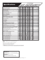
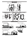
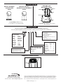
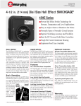
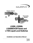
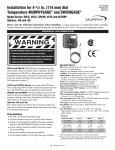
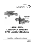
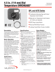
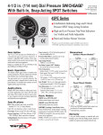
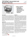
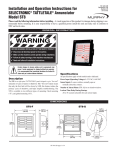
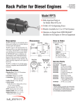
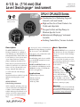
4-1/2 in. (114 mm) Dial
Level Swichgage® instrument
OPLH-94122B
Revised 03-06
Catalog Section 15
OPLH / OPLHACS Series
R
■
Selected configurations
are third party listed. Consult
FWMurphy for details.
OPLHACS
Combination Level Indicating Gage and
Critical Level Limit Switch
■ High and Low Level Limit Contacts Are
Visible and Adjustable
■ Designed to Start and Stop Pumps to
Maintain Specific Levels
■ Indication only Murphygage® instrument
Available
■ Latching Control Relay Versions Available
OPLHFC
Description
The OPLHC/OPLHACS Series Level
Swichgage instruments are combination
level indicating gages with adjustable low
and high limit switches. Limit switches can
be wired directly to electric pilot circuits to
operate alarms, shutdown or start/stop
pumps to maintain predetermined levels.
Surface mount or panel mount enclosure is
available for both model series. All models
feature a 4-1/2 in. (114 mm) dial for easy
viewing. Adjustable limit switches are
accessible from front of the Swichgage
instrument.
Specialized models are available for specific
applications involving engines or electric
motors.
OPLHC/OPLHACS
Series Swichgage instruments
include 2-adjustable, pilot duty, pointer type
contacts. Contacts have self-cleaning motion
to enhance electrical continuity. Models are
available with a rugged bourdon-tube or 316
stainless steel bellows sensing element for
greater accuracy and sensitivity in lower
ranges.
A “freeze-proof” sensor of 316 stainless steel
with Buna-N rolling diaphragm, is available.
The “freeze-proof” sensor (OPLHAFP)
inserts approx., 2 in. (52 mm) inside a tank.
OPLHBP/OPLHABPS
Internal latching control relays are available
to provide ON/OFF automation for electric
motor applications.
OPLHC and OPLHACS series are available in indication only Murphygage models
(OPLHAGS). See Page 2 to determine the
model for your application.
Applications
• Saltwater Disposal Systems
• Waterflood Systems
• Diesel Day Tanks
• Oil Storage Tanks
Basic Operation
The OPLHC/OPLHACS series operate from
static head pressure. Pressure is transmitted
to the process connection of the Swichgage
instrument.
From here the pressure flexes the bourdon
tube or operates the 316 stainless steel bellows (depending on which model you have).
The bourdon tube/bellows operAdjustment
ates the stainless
Knob
C
B
steel rotary
geared movement
which in turn operates
the indicating pointer on A
the face of the dial. When
the pointer (A) closes with the
limit contact (B), a control circuit
(C) is completed and signals an alarm and/or
shutdown or starts/stops a pump.
Warranty
A limited warranty on materials and workmanship
is given with this FW Murphy product. A copy of
the warranty may be viewed or printed by going to
www.fwmurphy.com/support/warranty.htm
OPLH-94122B page 1 of 4
HA
OP CES
LH
OP BP
LH
OP A B P
LH S
OP BP
LH E
A
OP BPE
LH S
OP G
LH
F
OP G
LH
OP AG
LH S
A
OP GE
LH S
A
OP FCS
LH
AF
GS
OP
L
OP
Specifications
LH
OP C
LH
OP FC
LH
C
OP E
LH
AC
S
OPLH / OPLHA Series
Enclosure Type (die cast aluminum)
• Surface mount, square case
• Panel mount, round case
• Panel mount, square case
Limit Switch Ratings
• Pointer Contacts: SPDT center off; 2 A, 30 VDC, 1 A, 125 VAC.
Latching Control Relay
• SPDT,10 A @ 120 VAC (standard)
• DPDT, 12 VDC (Optional)
• DPDT, 24 VAC (Optional)
• DPDT, 24 VDC (Optional)
Sensing Element
• Bourdon Tube, Bronze/Brass (standard)
• Bellows, 316 Stainless Steel (standard)
Process Connections
• 1/4 NPT Male
• 1/4 NPT Female
• 2 NPT Male
Geared Movement: 300 series stainless steel.
Accuracy (standard calibration is for water)
• ±2% first/last quarters of scale, 1% middle half scale. (1)
• 3% full scale.
OPTIONS AVAILABLE (specify when ordering)
• Environment sealed for isolation from the elements (ES). (2)
• Explosion-proof case; Class I, Div. 2, Groups C & D (EX)
• Explosion-proof less case; internal gage
mechanism without case (EL)
• Less case; internal gage mechanism without case (LC)
• Tickler contact (TA)
RANGES AVAILABLE (specify when ordering)
• 0–5 ft. (0–1.5 m) dual scale dial
• 0–10 ft. (0–3 m) dual scale dial
• 0–20 ft. (0–6 m) dual scale dial
• 0–30 ft. (0–9 m) dual scale dial
• 0–60 ft. (0–18 m) dual scale dial
• 0–120 ft. single scale dial
• 0–3.6 metres single scale dial
• 0–4 metres single scale dial
• 0–6 metres single scale dial
• 0–9 metres single scale dial
(1)
(2)
Bourdon tube (OPLHC) models in the 20 ft. (6 m) range have an accuracy of 3% full scale.
ES option available for the 20 ft. (6 m) range models and above.
NOTES:
• Options may not be available in combination. Consult factory.
• Over range is not to exceed 10% FS above full range.
• Calibration is for water. Specify for other liquids.
• Add TOTAL height of liquid above the pressure connection to determine correct range (dial scale).
For elevated tanks substract the tank elevation from gage reading to determine actual tank level.
Shipping Dimensions
Item Dimensions: 16 x 11 x 5-1/2 in. (406 x 279 x 140 mm).
Explosion-proof models: 12 x 12 x 9 in. (305 x 305 x 229 mm).
Shipping Weights
Item Weight: 8 lb. (3.6 kg) approximately.
Explosion-proof models: 22 lb. (10 kg) approximately.
OPLH-94122B page 2 of 4
Dimensions
Surface / Panel Mount Enclosure (Square Case)
8-7/16 in.
(214 mm)
3-3/8 in.
(86 mm)
3-15/16 in.
(100 mm)
1/2 NPT
conduit
NOTE:
Panel mount
square case models
do not include
mounting flange and
include bolt circle
shown in Panel Mount
Enclosure versions
(see below).
4-1/32 in.
(102 mm)
Mounting Holes
9/32 in. (7 mm)
diameter 3 places.
Not available on
panel mount
square case.
Process Connection
1/4 NPT male on
bourdon tube models
and 1/4 NPT female
on bellows models.
7-7/8 in.
(200 mm)
Panel Mount Enclosure
(Round Case)
Explosion-proof Enclosure (“EX” Option)
3/8-16 UNC-2B
7/8 in. (22 mm)
deep, 4 places.
8 in.
(203 mm)
2-57/64 in.
(73 mm)
5-7/16 in.
(138 mm)
Surface
6-3/4 in.
(171 mm)
6-25/64 in.
(162 mm)
1/2 NPT
optional
rear or side
conduit
8 in.
(203 mm)
1/4 in. (6 mm) dia.
holes (3 places.)
on 5-13/64 in. 120
(132 mm) b.c.
(bolt circle),120
apart, clocking
as shown
120
6-3/4 in.
(171 mm)
120
Mounting Hole
4-3/4 in. (121 mm)
diameter.
Panel
Mounting Hole
7-35/64 in. (192 mm)
diameter. Not required
for surface mounting.
Process Connection
1/4 NPT Male.
Rear mounting holes
for surface mounting
3/8-16 UNC-2B
7/8 in. (22 mm)
deep, 4 places.
Removable lid
to access adjustable
contact knobs.
Process Connection
1/4 NPT Female
Typical Applications
Above Ground Tank
Below Ground Tank
Flow regulator
(recommended)
Tank
SWICHGAGE®
SWICHGAGE ®
Pressure
regulator
Pressure
regulator
Air compressor
Air compressor
Head
Pressure
Ground surface
Flow regulator
(recommended)
Underground tank
(vented)
Direct and Remote Tank
Tank
1 foot
Direct Mount
SWICHGAGE®
Remote
SWICHGAGE®
with Sensing Line
Underground
OPLH-94122B page 3 of 4
Internal Wiring
OPLHC, OPLHACS,
and OPLHAFP
Series
OPLHBP, and
OPLHABPS Series
OPLHCE, OPLHFC,
OPLHACES and OPLHAFCS
Series
YELLOW
COMMON
4
BLUE
3
RESET
5
SET
1
7
4
3
9
6
BROWN
8
WHITE
NEUTRAL
1
B
A
ORANGE
120 VAC
RED
= 18 GA.
= 16 GA.
Red White Black
Red White Black
LINE
Contact Ratings: SPDT center off;
2 A, 30 VDC, 1 A, 125 VAC pilot duty.
2
LOW
(RESET)
6
BLACK
HIGH
(SET)
Contact Ratings: SPDT dry relay contacts,
10 A, 125 VAC.
How to Order
Specify model number. NOTE: No designator is required for Standard configurations.
Also, list options in alphabetical order (A to Z). Place a dash (–) between each option. See example below.
OPLHBP –
– 2 – 30 – TA
Options (see Specifications on page 2
for availability)
Base Part Numbers
OPLHG
OPLHGE
OPLHC
OPLHBP
OPLHAGS
OPLHACS
OPLHABPS
OPLHAFCS
OPLHAFGS
OPLHFG
ES = Environmentally sealed
EX = Explosion-proof
EL = (EXLC) Explosion-proof less case
LC = Less case
TA = (TCA) Tickler contact
OPLHFC
OPLHCE
OPLHABPGS
OPLHBPE
OPLHAGES
OPLHACES
Range/Scale (specify in feet)*
45LHE
45LHEF
45LHEBP
Bellows
Latching Control Relay Voltage
(applies to “BP” models only)
Bourdon Tube/Bellows
Blank = 120 VAC
2 = 12 VDC
4 = 24 VDC
OPLHC Standard=Bronze/Brass
OPLHACS Standard=316 Stainless Steel
05 = 0-5 ft.
10 = 0-10 ft.
20 = 0-20 ft.
30 = 0-30 ft.
60 = 0-60 ft.
120 = 0-120 ft.
X
X
X
X
Tube
X
X
X
X
*Standard calibration is for water–specify
for other.
Tamperproof Contact Accessory
Order 05000610
Knob
Lock
Limit
Switch
Knobs
www.fwmurphy.com
918.317.4100 Email: [email protected]
In order to consistently bring you the highest quality, full featured products, we reserve the right to change our
specifications and designs at any time. MURPHY, the Murphy logo, Swichgage® and Murphygage® are registered
and/or common law trademarks of Murphy Industries, Inc. This document, including textual matter and illustrations, is copyright protected by Murphy Industries, Inc., with all rights reserved. (c) 2006 Murphy Industries, Inc.
OPLH-94122B page 4 of 4